US9249044B2 - Glass bending method and apparatus - Google Patents
Glass bending method and apparatusDownload PDFInfo
- Publication number
- US9249044B2 US9249044B2US13/324,992US201113324992AUS9249044B2US 9249044 B2US9249044 B2US 9249044B2US 201113324992 AUS201113324992 AUS 201113324992AUS 9249044 B2US9249044 B2US 9249044B2
- Authority
- US
- United States
- Prior art keywords
- glass sheet
- mold
- sag
- glass
- shape
- Prior art date
- Legal status (The legal status is an assumption and is not a legal conclusion. Google has not performed a legal analysis and makes no representation as to the accuracy of the status listed.)
- Active, expires
Links
- 239000011521glassSubstances0.000titleclaimsabstractdescription123
- 238000005452bendingMethods0.000titleclaimsabstractdescription57
- 238000000034methodMethods0.000titleclaimsabstractdescription32
- 230000036961partial effectEffects0.000claimsabstractdescription35
- 239000002131composite materialSubstances0.000claimsabstractdescription34
- 238000010438heat treatmentMethods0.000claimsdescription6
- 238000001816coolingMethods0.000claimsdescription2
- 239000002699waste materialSubstances0.000description11
- 238000013459approachMethods0.000description10
- 238000004519manufacturing processMethods0.000description9
- 239000005357flat glassSubstances0.000description6
- 230000008901benefitEffects0.000description5
- 238000005304joiningMethods0.000description5
- 238000000465mouldingMethods0.000description5
- 230000002829reductive effectEffects0.000description4
- 230000000694effectsEffects0.000description3
- 230000008569processEffects0.000description3
- 230000007547defectEffects0.000description2
- 230000002401inhibitory effectEffects0.000description2
- 239000000463materialSubstances0.000description2
- 239000002184metalSubstances0.000description2
- 229910052751metalInorganic materials0.000description2
- 238000007493shaping processMethods0.000description2
- 239000007787solidSubstances0.000description2
- 230000007704transitionEffects0.000description2
- 238000013519translationMethods0.000description2
- RYGMFSIKBFXOCR-UHFFFAOYSA-NCopperChemical compound[Cu]RYGMFSIKBFXOCR-UHFFFAOYSA-N0.000description1
- BQCADISMDOOEFD-UHFFFAOYSA-NSilverChemical compound[Ag]BQCADISMDOOEFD-UHFFFAOYSA-N0.000description1
- ATJFFYVFTNAWJD-UHFFFAOYSA-NTinChemical compound[Sn]ATJFFYVFTNAWJD-UHFFFAOYSA-N0.000description1
- 230000009471actionEffects0.000description1
- 230000004075alterationEffects0.000description1
- 230000008859changeEffects0.000description1
- 229910052802copperInorganic materials0.000description1
- 239000010949copperSubstances0.000description1
- 238000005520cutting processMethods0.000description1
- 230000007423decreaseEffects0.000description1
- 230000003247decreasing effectEffects0.000description1
- 238000000151depositionMethods0.000description1
- 230000008021depositionEffects0.000description1
- 230000008676importEffects0.000description1
- 230000006872improvementEffects0.000description1
- 238000010030laminatingMethods0.000description1
- 230000000670limiting effectEffects0.000description1
- 239000011159matrix materialSubstances0.000description1
- 238000005259measurementMethods0.000description1
- 238000001465metallisationMethods0.000description1
- 150000002739metalsChemical class0.000description1
- 230000003287optical effectEffects0.000description1
- 238000005498polishingMethods0.000description1
- 238000002360preparation methodMethods0.000description1
- 238000012545processingMethods0.000description1
- 230000009467reductionEffects0.000description1
- 238000002310reflectometryMethods0.000description1
- 230000002441reversible effectEffects0.000description1
- 238000007665saggingMethods0.000description1
- 229910052709silverInorganic materials0.000description1
- 239000004332silverSubstances0.000description1
- 229910052718tinInorganic materials0.000description1
- 239000011135tinSubstances0.000description1
- 238000013022ventingMethods0.000description1
Images


Classifications
- C—CHEMISTRY; METALLURGY
- C03—GLASS; MINERAL OR SLAG WOOL
- C03B—MANUFACTURE, SHAPING, OR SUPPLEMENTARY PROCESSES
- C03B23/00—Re-forming shaped glass
- C03B23/02—Re-forming glass sheets
- C03B23/023—Re-forming glass sheets by bending
- C03B23/025—Re-forming glass sheets by bending by gravity
- C03B23/0252—Re-forming glass sheets by bending by gravity by gravity only, e.g. sagging
- C—CHEMISTRY; METALLURGY
- C03—GLASS; MINERAL OR SLAG WOOL
- C03B—MANUFACTURE, SHAPING, OR SUPPLEMENTARY PROCESSES
- C03B23/00—Re-forming shaped glass
- C03B23/0026—Re-forming shaped glass by gravity, e.g. sagging
- C—CHEMISTRY; METALLURGY
- C03—GLASS; MINERAL OR SLAG WOOL
- C03B—MANUFACTURE, SHAPING, OR SUPPLEMENTARY PROCESSES
- C03B23/00—Re-forming shaped glass
- C03B23/02—Re-forming glass sheets
- C03B23/023—Re-forming glass sheets by bending
- C03B23/035—Re-forming glass sheets by bending using a gas cushion or by changing gas pressure, e.g. by applying vacuum or blowing for supporting the glass while bending
- C03B23/0352—Re-forming glass sheets by bending using a gas cushion or by changing gas pressure, e.g. by applying vacuum or blowing for supporting the glass while bending by suction or blowing out for providing the deformation force to bend the glass sheet
- C03B23/0357—Re-forming glass sheets by bending using a gas cushion or by changing gas pressure, e.g. by applying vacuum or blowing for supporting the glass while bending by suction or blowing out for providing the deformation force to bend the glass sheet by suction without blowing, e.g. with vacuum or by venturi effect
- Y—GENERAL TAGGING OF NEW TECHNOLOGICAL DEVELOPMENTS; GENERAL TAGGING OF CROSS-SECTIONAL TECHNOLOGIES SPANNING OVER SEVERAL SECTIONS OF THE IPC; TECHNICAL SUBJECTS COVERED BY FORMER USPC CROSS-REFERENCE ART COLLECTIONS [XRACs] AND DIGESTS
- Y02—TECHNOLOGIES OR APPLICATIONS FOR MITIGATION OR ADAPTATION AGAINST CLIMATE CHANGE
- Y02P—CLIMATE CHANGE MITIGATION TECHNOLOGIES IN THE PRODUCTION OR PROCESSING OF GOODS
- Y02P40/00—Technologies relating to the processing of minerals
- Y02P40/50—Glass production, e.g. reusing waste heat during processing or shaping
- Y02P40/57—Improving the yield, e-g- reduction of reject rates
Definitions
- Embodiments of the subject matter described hereinrelate generally to forming of curved glass sheets. More particularly, embodiments of the subject matter relate to sag-bending deformation of glass sheets.
- Glass mirrorsincluding those with a parabolic shape, are useful for solar applications.
- parabolic-shaped mirrorscan be used for solar concentrator systems.
- a solar concentrator systemis one where sunlight is reflected with increased, concentrated intensity on a receiving unit. Because of the optical effects associated with parabolic-shaped mirrors, such shapes are useful for focusing concentrated sunlight.
- Forming parabolic mirrorscan be accomplished through sag-bending techniques.
- it can be challenging to form a parabolic-shaped glass sheetbecause the curve deviation from a flat sheet of glass increases as the length of the glass sheet increases.
- longer mirrorshave portions that are deformed a small amount and a greater amount.
- the dissimilarity in deformation amountscan cause increased difficulty in accurately controlling the shape of the glass sheet during deformation.
- Solar concentrator systemscan be sensitive to minor variations in operating conditions, such as mirror shape, which can affect the location of concentrated sunlight on the receiving unit, the shape of the concentrated sunlight reflected area, and other aspects of the system, all of which contribute to the efficiency and power output of the system. Accordingly, solar concentrator systems benefit from components made to very high precision. Thus, crafting parabolic mirrors with minimized defects or deviations from an ideal shape provides a benefit to a solar concentrator system.
- FIG. 1is an illustration of a parabolic glass mold
- FIG. 2is a side view of the parabolic glass mold of FIG. 1 ;
- FIG. 3is a top view of the parabolic glass mold of FIG. 2 ;
- FIG. 4is an illustration of a parabola
- FIG. 5is an illustration of another parabola with a designated section
- FIG. 6is an illustration of the designated section of FIG. 5 and transformed section
- FIG. 7is an illustration of an embodiment of a linear-square root composite shape
- FIG. 8is another illustration of an embodiment of a linear-square root composite shape
- FIG. 9is yet another illustration of an embodiment of a linear-square root composite shape
- FIG. 10is an embodiment of a sag-bending glass mold having a linear-square root composite shape
- FIG. 11is a side view of the sag-bending glass mold of FIG. 10 ;
- FIG. 12is a top view of the sag-bending glass mold of FIG. 11 ;
- FIG. 13is a side view of a sag-bending glass mold having a linear-square root composite shape with associated glass sheet;
- FIG. 14is a side view of the sag-bending glass mold of FIG. 13 forming the glass sheet into a partial-parabolic shape
- FIG. 15Ais a side view of the sag-bending glass mold of FIG. 14 with the shaped glass sheet removed;
- FIG. 15Bis a side view of the sag-bending glass mold of FIG. 15A with the shaped glass sheet separated;
- FIG. 16is a side view of embodiments of two sag-bending molds with adjacent glass sheets
- FIG. 17is a side view of the embodiments of FIG. 16 after sag-bending the adjacent glass sheets;
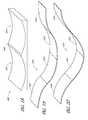
- FIG. 18is another embodiment of a sag-bending glass mold having a linear-square root composite shape
- FIGS. 19 and 20are different embodiments of sag-bending glass molds having joined linear-square root composite shapes.
- FIG. 21is an illustration of a method for forming a partial parabolic glass sheet.
- inhibitis used to describe a reducing or minimizing effect. When a component or feature is described as inhibiting an action, motion, or condition it may completely prevent the result or outcome or future state completely. Additionally, “inhibit” can also refer to a reduction or lessening of the outcome, performance, and/or effect which might otherwise occur. Accordingly, when a component, element, or feature is referred to as inhibiting a result or state, it need not completely prevent or eliminate the result or state.
- a partial parabolic shapethat is, a portion or segment of a parabola, is a desirable for use in some embodiments of solar concentrator applications.
- the glass referred tocan be used for creating a mirror, as would be used in a reflector element of a solar concentrator.
- a glass sheetcan be processed to create a mirror sheet through the addition of a reflective layer to an exposed surface of the glass sheet, or by embedding a reflective layer between glass sheets.
- Such processingcan include the metallization of a surface of the glass, including deposition of successive metal layers, including tin, silver, copper, and other metals, to produce a reflective layer.
- the reflectivityis uni-directional.
- the glass sheets describedcan, in some embodiments, be later processed to produce mirrors, including mirrors appropriate for concentrating photovoltaic or concentrating solar thermal applications.
- the glass sheetscan comprise one or more reflective surfaces before the bending techniques described herein are applied.
- bending the glass sheet to produce a curved glass sheetcan also describe a process for bending a glass sheet with a reflective surface to produce a curved mirror. Additional process steps, such as laminating or polishing may also be used to produce a completed mirror from a curved glass sheet without deviating from the advances described herein.
- concentrator glass sheetscan be wider than they are long, sometimes having an aspect ratio of 5:1 or greater.
- This aspect ratiointroduces additional challenges because high-aspect ratio glass sheets do not easily sag at the differing amounts required by a partial parabolic shape. It is preferable to have a lower aspect ratio for more uniform sag-bending.
- the inventorshave discovered that it is possible to form a partial parabolic shape from a non-parabolic-shaped mold. Additionally, the non-parabolic shape can have one side with a flat edge. Multiple non-parabolic shapes can be molded by joining the flat edges, thereby decreasing the aspect ratio of the molded glass. Further, this can be accomplished with little to no waste glass, and while simultaneously increasing manufacturing throughput.
- the advantageous end resultis that partial parabolic curved glass sections can be formed with lower cost, greater simplicity, and at a faster rate, than previously possible.
- FIG. 1illustrates a typical mold 100 for forming a parabolic glass sheet as used in the art.
- the mold 100has an upper surface 102 which can be solid or distributed across several longitudinal or lateral rib portions.
- the mold 100has a cross-sectional shape as shown in FIG. 2 . With reference to both FIGS. 1 and 2 , the mold 100 can be considered to have an origin 104 and an upper point 106 .
- the parabolic shape of the upper surface 102is used to form the shape of a curved glass segment when flat glass is heated to sag bend onto it.
- Typical molds, such as mold 100are constructed to form a single parabolic shape for use in molding a single glass sheet.
- ⁇ 1 and ⁇ 2two portions of the curved upper surface 102 are identified as ⁇ 1 and ⁇ 2 .
- ⁇ 1indicates an area near the imaginary origin 104
- ⁇ 2indicates a region further from the origin 104 .
- the rate of change of the curved upper surface 102 from a flat vertical shapeis significantly higher in the region of ⁇ 2 than in ⁇ 1 .
- the temperature to which the glass sheet must be heatedincreases corresponding to the amount of deflection from the flat shape that the glass will be curving.
- a shallow curved shapecan be formed at a lower temperature than a deeply-curved shape.
- the glass sheetWhen sag-bending a flat glass sheet onto the upper surface 102 , the glass sheet will need a greater amount of heat in the region near ⁇ 2 than near ⁇ 1 . Additionally, because of the slope of curvature of the region near ⁇ 2 , some localized deformation in the glass may occur in addition to bending from a flat shape to match the curve of the upper surface 102 . These considerations increase manufacturing complexity and cost.
- FIG. 3illustrates a top view of the mold 100 .
- This viewpermits display of the relative width w and length l.
- the ratio of w to lforms the aspect ratio.
- the ratioas can be seen, although not to scale, can be as high as 3:1 or greater. This high aspect ratio additionally complicates manufacture.
- FIG. 4illustrates a parabola P.
- a parabolais a conic section and in a plane is the locus of points that are equidistant between a point focus and a line directrix.
- the parabola Pis formed in relation to the focus f and directrix d. Coordinate axes x and y are provided for reference.
- the focus fis used for illustrative purposes, it should not be confused with the focus of the finished mirror or curved glass used in solar concentrating applications, whether thermal or photovoltaic, or otherwise benefiting from the glass produced.
- a parabolarefers to such a shape as illustrated here, and parabolic is used to describe shapes having properties associated with the shape.
- P ( x )ax 2 +bx+c; where a, b, and c represent constants.
- Such a parabolais useful for solar concentrator applications for certain values of the constants.
- itis a partial parabolic shape that can also be used for solar concentrator applications.
- P 1 ( x )0.001192 x 2 +0.109046544 x
- FIG. 5illustrates a portion 202 of parabola P between points A 0 and B 0 .
- Point A 0corresponds to the point of the parabola P a distance A from the origin and with a height from the origin of P(A).
- (A, P(A))is the point A 0 .
- point B 0is the point of the parabola P that is a distance B from the origin and has a height of P(B).
- Portion 202represents a partial parabolic shape that can be used in a solar concentrator application. It can be inefficient, however, to form the entire parabola P from (0, P(0)) to (B, P(B)), subsequently discarding the portion of parabola P between (0, P(0)) and (A, P(A)), to obtain portion 202 for use in a solar concentrator. This is the approach typically used by mold 100 , such that the origin 104 corresponds to the point (0, P(0)) and the upper point 106 corresponds to the point (B, P(B)). For one such portion 202 corresponding to the exemplary parabola P 1 (x), the portion can be between 45.791 and 483.241 on the x axis.
- FIG. 6illustrates the discovery by the inventors that portion 202 can be transformed into portion 212 for simplification of manufacture at reduced cost and increased throughput.
- portion 202can be translated such that point (A, P(A)) is located at the origin.
- point A 0has been translated to point A 1 located at (0, 0).
- Point B 0is altered by translation to point B 1 .
- this translationreduces the waste associated with forming portion 202 .
- the slope of the portion 202 as it approaches the origin (0, 0)does not approach a horizontal, or zero slope. Put another way, the tangent of P(x) does not approach zero as P(x) approaches the origin from the positive x direction. This can make manufacture challenging.
- P(x) and corresponding portion 202can be rotated downward by a negative angle ⁇ to produce Q(x) and corresponding portion 212 .
- the negative angle ⁇is defined as the angle necessary to rotate portion 202 such that the slope of 202 approaches zero as Q(x) approaches the origin from the positive x direction.
- the value of ⁇varies as the parabola P(x) varies, but can be anywhere from 0.01 to 90 degrees, whether measured negatively or positively.
- the shape of the curve of Q(x)is referred to as a linear square root composite shape.
- the values of a, b, and c associated with parabola P(x)determine the value of negative angle ⁇ and both determine the values of constants d, e, f, g, and h. Accordingly, the exact shape of curve Q(x) will be determined by the shape of parabola P(x) desired for the embodiment.
- the calculation of x′ and Q(x′), where x′ corresponds to the x coordinate of a point on the curve (x, P(x)), and Q(x′) corresponds to the y coordinate,is performed by the use of a rotation matrix [R] on P(x) such that:
- curve Q(x)will be determined by the shape of parabola P(x) and the selected endpoints desired for the embodiment. Therefore, for every portion of a parabola P(x), such as portion 202 , there will exist exactly one transformed portion of a linear square root composite shaped curve, such as portion 212 , of Q(x). Portion 212 corresponds exactly to the curvature of portion 202 , except that is has been translated and rotated from the original illustration in FIG. 5 .
- a sag-bending moldwhich is used to fabricate portion 212 , having the curved shape of portion 212 , will produce a curved portion of glass which matches the curve of portion 202 .
- the portion 212is advantageously simpler, faster, and less complex to manufacture than portion 202 or parabola P(x), greatly reducing cost.
- the non-parabolic shape of the linear square root composite curved shapecan be used to create, by molding for example, a partial parabolic curve shape that previously could only be formed by using a parabolic shaped mold.
- a non-parabolic surface on a moldcan therefore be used to produce a partial parabolic shaped glass surface after sag-bending molding. All references to parabolic and non-parabolic shapes are made with respect to the original defined coordinate references in which the parabola is first described.
- FIG. 7illustrates that further improvement can be possible by taking advantage of the zero-slope at endpoint A 2 by rotating the portion 212 around the y axis to obtain portion 222 .
- Portions 212 and 222have overlapping endpoints A 2 and A 3 at the origin.
- Endpoint B 2 of portion 212is at the same place as calculated above and illustrated with respect to FIG. 6 .
- Endpoint B 3 of portion 222has the same height as B 2 while extending in the negative x direction an equal distance from the origin as B 2 is in the positive x direction, as illustrated.
- portions 212 and 222can meet smoothly at the origin with a zero slope and form a double-wide joined portion.
- Each half, if divided at the y axisforms a partial parabolic shape of the type illustrated in FIG. 5 and desired for solar concentrator systems.
- FIG. 8illustrates an inversion pairing of portion 212 .
- the portion 212has been further rotated such that endpoint B 2 is now positioned at the origin and portion 212 has been oriented such that the curve, which is the inverse or Q ⁇ 1 (x) of Q(x), still has a zero slope, or horizontal tangent, at the origin as Q ⁇ 1 (x) approaches the origin from the positive x direction. Accordingly, endpoint A 2 now is positioned at the upper right end of the portion 212 .
- portion 212appears to have a shallower upward slope in FIG. 7 than in FIG. 8 , and the inversion of curve Q(x) in FIG. 8 has produced a sharper upward slope, in actual practice, the reverse may be true, and all illustrated elements are shown for descriptive purposes. Accordingly, such features may not be to scale for purposes of clarity of description.
- portion 222which has a similar positioning of end points A 3 and B 3 as mirrored across the y axis.
- FIG. 9illustrates yet another embodiment of a variation of FIG. 7 where portions 212 and 222 have been rotated about the x axis.
- the curvesextend in the negative y direction as they extend outward from the origin.
- Such a rotationcan also be performed on the embodiment shown in FIG. 8 , producing downward curves of the illustrated inverted portions 212 , 222 of FIG. 8 .
- portion 222is said to be the mirror image of portion 212 .
- FIGS. 6-9can be used to form a mold for sag-bending a flat glass sheet into the partial parabolic shape desired.
- Several of the shapeswill produce multiple partial parabolic curved sections or segments, such as the shape illustrated in FIG. 7 or 8 , which can then be separated, divided, or cut into the desired part for use.
- FIG. 10illustrates an improved mold 300 for use in forming partial parabolic shaped glass sections formed by sag-bending.
- the mold 300can be a perimeter-support mold with a plurality of ribs 308 forming an upper surface 302 .
- the mold 300can be formed as a solid component with a single upper surface, while in other embodiments, the upper surface can be distributed across multiple components, such as internal longitudinal or lateral ribs.
- the mold 300 of FIG. 10illustrates longitudinal ribs 308 which extend between the two outer edges 306 of the mold 300 .
- the ribs 308can be any thickness or width as desired for operation of the mold 300 .
- the mold 300is shown from the side, illustrating the cross-section of the upper surface 302 , which has a variable height. It should be noted that mold 300 has been simplified for descriptive purposes. Some embodiments of the mold 300 can include ports and inlets and outlets for gas venting and vacuum, as well as clips, gutters, heating features, and any other appropriate components for use in a sag-bending mold, including a perimeter-supported sag-bending mold.
- the upper surface 302has outer edges 306 .
- the mold 300can have an upper surface 302 with a linear square root composite curved shape, in accordance with the shapes and their variations as described above.
- the mold 300can have a shape similar to that illustrated in FIG. 7 , where points A 2 and A 3 would lie at the midpoint of the upper surface 302 , approximating the origin of FIG. 7 , and points B 2 and B 3 would correspond to the points of the upper surface 302 at the outer edges 306 .
- the upper surface 302can also be reduced or increased in scale as desired, such for a negative or positive mold. Such a surface as the upper surface 302 can be continuous or spread across any ribs 308 of the mold 300 .
- FIG. 11additionally includes regions marked ⁇ 3 and ⁇ 4 , similar to the respective marked regions ⁇ 1 and ⁇ 2 of FIG. 2 , described above.
- Each indicatorreferences the same portion of the upper surface of the respective mold 100 , 300 .
- ⁇ 3which references a position similar to that referenced by ⁇ 1 has a shallower curve than ⁇ 1 .
- ⁇ 4references a position similar to that of ⁇ 2 .
- ⁇ 4is shallower than ⁇ 2 .
- the improved curve of mold 300can reduce local deformation during sag bending as compared to a parabolic mold 100 . Additionally, the reduced disparity between ⁇ 3 and ⁇ 4 , as compared to between ⁇ 1 and ⁇ 2 correspondingly reduces manufacturing complexity and, hence, cost.
- FIG. 12illustrates a further advantage of joining linear square root composite shapes to form a mold, such as mold 300 .
- the length/of the mold 300is increased to at least double that of mold 100 in FIG. 3 .
- the aspect ratiodecreases from that of FIG. 3 , which was about 3:1 to about 1.5:1, or, where the width w is varied, to any other aspect ratio of 2:1, 1.6:1, 1.15:1, or even less than one.
- FIGS. 18-20it can be seen that molds with aspect rations much less than 1 can be formed.
- FIGS. 13-17illustrates a mold 400 for sag-bending glass to a particular shape. Unless otherwise indicated, the numerical indicators in FIGS. 13-17 designate components and features similar to those in FIGS. 10-12 , except that they have been incremented by 100 .
- the mold 400can be a perimeter-supported mold for sag-bending planar or flat glass sheets, such as sheet 450 .
- Sheet 450can have a midpoint 452 , dividing the sheet 450 into first side 454 and second side 456 .
- the sheet 450can have a lower surface 460 .
- the sheet 450can be positioned on or above the upper surface 402 of the mold 400 , as depicted in FIG. 13 .
- the sheet 450has been replaced with curved sheet 470 , formed by heating the sheet 450 until it reaches a temperature sufficient to sag the glass mirror sheet to deform downwards toward the upper surface 402 of the mold 400 .
- the mold 400can then support the lower surface 460 of the sheet with its upper surface 402 , molding the glass sheet 450 to the desired shape as curved sheet 470 .
- a downward forcecan be imparted to sheet 450 to cause it to curve to follow upper surface 402 .
- Such a forcecan be caused by a press from above the sheet 450 directed downward and forcing the sheet 450 into the mold 400 .
- the mold 400can incorporate one or more vacuum ports which draw the sheet 450 downward toward and onto the upper surface 402 of the mold 400 .
- the curved sheet 470can be separated from the mold 400 , as shown in FIG. 15A .
- the curved sheet 470can be separated, cut, or divided at its midpoint 472 as shown in FIG. 15B .
- the curved sheet 470is thus divided into first section 474 and second section 476 , each of which can have a partial parabolic shape, despite the linear square root composite curved shape of the upper surface 402 against which it is formed.
- the mold 400can include a flat portion between partial parabolic shapes, such as near the middle of the mold 400 to provide material between the two sections for kerf, although such a flat portion is desirably minimized to inhibit waste material.
- FIG. 16further illustrates the advantage to aspect ratio caused by the use of a linear square root composite curve shape on a sag-bending mold.
- a mold 500which is a double-sided parabolic glass mold
- a mold 530which is a double-sided linear square root composite curve shape similar to those shapes illustrated in FIGS. 7 and 8
- Both molds 500 , 530form similarly long glass sheets 510 and 540 respectively.
- the glass sheets 510 and 540have been formed into curved sheets 512 , 542 respectively. As shown above, if each glass sheet 512 , 542 is separated at its midpoint, and waste region 514 removed, they will form substantially identical partial parabolic shapes.
- the glass sheet 542 formed by mold 530if separated at or near the midpoint, however, is formed by a greatly advantageous process. Because the mold 530 uses a linear square root composite shape for its molding surface, the aspect ratio is superior to the parabolic shape of mold 500 , permitting for easier sagging at a lower temperature. Additionally, because there is less vertical deformation when mold 530 is used, localized deformation effects are inhibited or eliminated, thereby increasing glass quality and ultimately solar system performance. Further, waste region 514 of curved sheet 512 is the region between partial parabolic portions, as can be understood by reference to FIG. 5 and the space between the origin and point A 0 in the figure.
- the waste region 514extends on both sides of the mold 500 , causing waste glass to be cut from the curved sheet 512 .
- glass sheets 510 , 540appear to be of equal length, sheet 510 is in fact slightly longer to account for the waste region 514 .
- the reduced waste enabled by using a linear square root composite shaped sag-bending moldfurther contributes to its cost superiority.
- FIG. 18illustrates another embodiment of a sag-bending mold 600 .
- a single mold 600can comprise several sections, such as first section 602 and second section 604 , for forming partial parabolic curves using a linear square root composite shaped upper surface.
- first section 602can correspond to a shape similar to that of FIG. 7
- second section 604can correspond to a shape similar to FIG. 9 .
- only two such sectionsare joined, while in other embodiments, three, four, five, or any practical number of such sections can be formed into a single mold.
- a transition surfacecan be present between joined sections to provide a gradual curvature section, if desired.
- a transition surfacecan be present between joined sections to provide a gradual curvature section, if desired.
- the glass sheetcan be separated, divided, or cut into the correct number of partial parabolic glass shapes.
- FIGS. 13-15illustrate a mold which may produce at least four such partial parabolic portions
- other moldscan produce six, seven, twelve, or any number of partial parabolic portions depending on how many linear square root composite shaped portions are joined.
- FIG. 19illustrates another embodiment of a mold similar to that of FIG. 18 , except that mold 620 is formed with four joined linear square root composite shaped portions.
- Portion 622can correspond to a linear square root composite curve portion similar to portion 212 of FIG. 7
- portion 624can correspond to portion 222 of FIG. 7
- Portion 626can correspond to portion 212 of FIG. 9 , except that it has been rotated to join with portion 622 with a slope matching the slope of portion 622 at the intersection therebetween.
- portions 622 and 626are joined as a smooth curve where they have a common tangent direction at the joining.
- portion 628has been oriented to be smoothly joined with portion 624 .
- a single moldsuch as mold 620 can thus be used to create four partial parabolic glass shapes which can be separated by dividing them, such as by cutting, at the location of portion joins.
- FIG. 20illustrates another embodiment of a mold 630 similar to that of mold 620 except that portion 632 corresponds to portion 212 of FIG. 8 , and portion 634 corresponds to portion 222 of FIG. 8 .
- Portions 636 and 638can be joined to their respective portions 632 , 634 in a manner similar to that described above with respect to FIG. 19 .
- various other portionscan be joined similarly to make other permutations. So long as the linear square root composite curved portions are joined smoothly as shown, or with a transition portion permitting a smooth joining, numerous possibilities for molds can be constructed. Additionally, more than four portions can be joined, and permutations of multiple-portion molds can be themselves smoothly joined to form molds which can produce any number of portions, even or odd, as desired for the embodiment. Thus, while two- and four-portion molds are shown, three-portion molds, eight-portion molds, or seventeen-portion molds, together with any other number, can all be formed using the techniques and advances described herein.
- method 700may refer to elements mentioned above in connection with FIGS. 1-18 .
- portions of method 700may be performed by different elements of the described system, e.g., mold 300 , upper surface 302 , or any other component, whether or not illustrated.
- methodcan include any number of additional or alternative tasks, the tasks shown in FIG. 19 need not be performed in the illustrated order, and method 700 may be incorporated into a more comprehensive procedure or process having additional functionality not described in detail herein.
- Method 700describes a method of forming a partial parabolic glass sheet, from a flat or planar glass sheet or curved into the desired shape.
- a planar glass sheetcan be positioned on or above a sag-bending mold having a linear square root composite shape on an upper, glass-supporting surface 702 .
- the glass sheetcan be heated to a first temperature 704 .
- the first temperaturecan be sufficient to cause the glass sheet to sag under its own weight or, in some embodiments, a downward force additionally can be applied.
- the planar glass sheetcan be caused to deform to follow the shape of the glass-supporting surface of the sag-bending mold.
- the curved glass sheetcan then be cooled below the first temperature 706 .
- the coolingcan be sufficient to harden the glass and ensure that it will retain its shape once removed from the mold.
- the curved glass sheetcan then be removed from the mold 708 .
- the curved glass sheetcan be removed once only partially cooled to its final rest temperature.
- the curved glass sheetcan be cooled entirely to its final rest temperature before separating the curved glass sheet from the mold.
- the curved glass sheetcan now be in the shape of a partial parabola appropriate for use in a solar concentrator or other application.
- the curved glass sheetafter separated from the sag-bending mold, can optionally be divided or separated into discrete partial parabolic portions, sections, or segments.
- a single mold having a linear square root composite curve shapecan be used to form several partial parabolic portions from a single planar glass sheet, advantageously with less localized defects and greater throughput than a parabolic mold.
Landscapes
- Chemical & Material Sciences (AREA)
- Engineering & Computer Science (AREA)
- Materials Engineering (AREA)
- Organic Chemistry (AREA)
- Re-Forming, After-Treatment, Cutting And Transporting Of Glass Products (AREA)
- Shaping Of Tube Ends By Bending Or Straightening (AREA)
- Optical Elements Other Than Lenses (AREA)
Abstract
Description
P(x)=ax2+bx+c;
where a, b, and c represent constants. Such a parabola is useful for solar concentrator applications for certain values of the constants. As mentioned above, however, for practical reasons, it is a partial parabolic shape that can also be used for solar concentrator applications. One such shape that can be used is:
P1(x)=0.001192x2+0.109046544x
Q(x)=dx+((√(ex+f))/g)+h;
where d, e, f, g, and h are constants. The shape of the curve of Q(x) is referred to as a linear square root composite shape. The values of a, b, and c associated with parabola P(x) determine the value of negative angle θ and both determine the values of constants d, e, f, g, and h. Accordingly, the exact shape of curve Q(x) will be determined by the shape of parabola P(x) desired for the embodiment. The calculation of x′ and Q(x′), where x′ corresponds to the x coordinate of a point on the curve (x, P(x)), and Q(x′) corresponds to the y coordinate, is performed by the use of a rotation matrix [R] on P(x) such that:
To produce a Q1(x) that would correspond to P1(x), the following constants are present:
| d | = 9.170396 | ||
| e | = 0.00052 | ||
| f | = 1.011891 | ||
| g | = 0.0000280154 | ||
| h | = 35906.3 | ||
Such constants correspond to the fact that P1(x) must be rotated by a negative angle θ approximately equal to 6.22° to achieve the linear square root composite curve Q1(x). Put another way, P1(x) must be rotated approximately 6.22° clockwise, toward the positive x axis, to achieve curve Q1(x). The values of a, b, and c associated with parabola P(x), along with the end points of interest, such as examples A0and B0, necessarily determine the value of negative angle θ and both necessarily determine the values of constants d, e, g, and h. Accordingly, the exact shape of curve Q(x) will be determined by the shape of parabola P(x) and the selected endpoints desired for the embodiment. Therefore, for every portion of a parabola P(x), such as
Claims (12)
Priority Applications (7)
| Application Number | Priority Date | Filing Date | Title |
|---|---|---|---|
| US13/324,992US9249044B2 (en) | 2011-07-01 | 2011-12-13 | Glass bending method and apparatus |
| AU2012271906AAU2012271906A1 (en) | 2011-07-01 | 2012-06-28 | Glass bending method and apparatus |
| PCT/US2012/044612WO2013006371A2 (en) | 2011-07-01 | 2012-06-28 | Glass bending method and apparatus |
| EP12807106.5AEP2726419A4 (en) | 2011-07-01 | 2012-06-28 | Glass bending method and apparatus |
| CN201280001051.5ACN103402934B (en) | 2011-07-01 | 2012-06-28 | Glass bending method and apparatus |
| CL2012003613ACL2012003613A1 (en) | 2011-07-01 | 2012-12-20 | A glass mold for gravity bending comprising a surface with support for the glass having a cross-sectional profile of varying height, the cross-sectional profile having a first part where the cross-sectional profile has a composite shape of linear square root; and method to form a glass sheet. |
| MA36646AMA35408B1 (en) | 2011-07-01 | 2014-01-02 | Method and apparatus for bending glass |
Applications Claiming Priority (2)
| Application Number | Priority Date | Filing Date | Title |
|---|---|---|---|
| US201161504147P | 2011-07-01 | 2011-07-01 | |
| US13/324,992US9249044B2 (en) | 2011-07-01 | 2011-12-13 | Glass bending method and apparatus |
Publications (2)
| Publication Number | Publication Date |
|---|---|
| US20130000356A1 US20130000356A1 (en) | 2013-01-03 |
| US9249044B2true US9249044B2 (en) | 2016-02-02 |
Family
ID=47389231
Family Applications (2)
| Application Number | Title | Priority Date | Filing Date |
|---|---|---|---|
| US13/251,053Expired - Fee RelatedUS9038421B2 (en) | 2011-07-01 | 2011-09-30 | Glass-bending apparatus and method |
| US13/324,992Active2034-11-03US9249044B2 (en) | 2011-07-01 | 2011-12-13 | Glass bending method and apparatus |
Family Applications Before (1)
| Application Number | Title | Priority Date | Filing Date |
|---|---|---|---|
| US13/251,053Expired - Fee RelatedUS9038421B2 (en) | 2011-07-01 | 2011-09-30 | Glass-bending apparatus and method |
Country Status (7)
| Country | Link |
|---|---|
| US (2) | US9038421B2 (en) |
| EP (2) | EP2726419A4 (en) |
| CN (2) | CN103402934B (en) |
| AU (2) | AU2012271906A1 (en) |
| CL (2) | CL2012003613A1 (en) |
| MA (2) | MA35257B1 (en) |
| WO (2) | WO2013006371A2 (en) |
Cited By (12)
| Publication number | Priority date | Publication date | Assignee | Title |
|---|---|---|---|---|
| USD822890S1 (en) | 2016-09-07 | 2018-07-10 | Felxtronics Ap, Llc | Lighting apparatus |
| USD832494S1 (en) | 2017-08-09 | 2018-10-30 | Flex Ltd. | Lighting module heatsink |
| USD832495S1 (en) | 2017-08-18 | 2018-10-30 | Flex Ltd. | Lighting module locking mechanism |
| USD833061S1 (en) | 2017-08-09 | 2018-11-06 | Flex Ltd. | Lighting module locking endcap |
| USD846793S1 (en) | 2017-08-09 | 2019-04-23 | Flex Ltd. | Lighting module locking mechanism |
| USD862778S1 (en) | 2017-08-22 | 2019-10-08 | Flex Ltd | Lighting module lens |
| USD862777S1 (en) | 2017-08-09 | 2019-10-08 | Flex Ltd. | Lighting module wide distribution lens |
| USD872319S1 (en) | 2017-08-09 | 2020-01-07 | Flex Ltd. | Lighting module LED light board |
| USD877964S1 (en) | 2017-08-09 | 2020-03-10 | Flex Ltd. | Lighting module |
| USD888323S1 (en) | 2017-09-07 | 2020-06-23 | Flex Ltd | Lighting module wire guard |
| US10775030B2 (en) | 2017-05-05 | 2020-09-15 | Flex Ltd. | Light fixture device including rotatable light modules |
| CN115989388A (en)* | 2021-08-16 | 2023-04-18 | 曼弗雷德.科恩穆勒 | Solar energy collector |
Families Citing this family (20)
| Publication number | Priority date | Publication date | Assignee | Title |
|---|---|---|---|---|
| US20100242953A1 (en)* | 2009-03-27 | 2010-09-30 | Ppg Industries Ohio, Inc. | Solar reflecting mirror having a protective coating and method of making same |
| PL67901Y1 (en)* | 2013-05-10 | 2015-07-31 | Proteh Spółka Z Ograniczoną Odpowiedzialnością | Form for producing the multi-curvature curved glass pane |
| US10348579B2 (en)* | 2013-07-17 | 2019-07-09 | Oracle International Corporation | Ubiquitous trouble management and E-service ecosystem for the internet of things |
| JP6264870B2 (en)* | 2013-12-13 | 2018-01-24 | 富士通株式会社 | Information providing apparatus, program, and system |
| US10336643B2 (en)* | 2014-08-01 | 2019-07-02 | Corning Incorporated | Glass shaping apparatus and methods |
| ES2733246T3 (en)* | 2015-05-27 | 2019-11-28 | Pilkington Group Ltd | Method and apparatus for forming glass sheets |
| US10277523B2 (en)* | 2015-12-31 | 2019-04-30 | Facebook, Inc. | Dynamically adapting to demand for server computing resources |
| CN106966573B (en)* | 2016-10-19 | 2023-02-21 | 郑州福耀玻璃有限公司 | Glass baking and bending die |
| CN106966572B (en)* | 2016-10-19 | 2023-03-24 | 郑州福耀玻璃有限公司 | Simple glass baking and bending die |
| CN109041574B (en) | 2017-04-10 | 2021-12-28 | 法国圣戈班玻璃厂 | Gravity bending mould with curved bearing surface for bending glass discs |
| US11065960B2 (en)* | 2017-09-13 | 2021-07-20 | Corning Incorporated | Curved vehicle displays |
| JP7045840B2 (en)* | 2017-12-08 | 2022-04-01 | 日鉄工材株式会社 | Metal leaf manufacturing equipment and electrode plate mounting body |
| CN110963682B (en)* | 2018-09-30 | 2023-08-11 | 惠州市赢合智能技术有限公司 | Curved glass production die and curved glass forming process |
| DE112018007688T5 (en)* | 2018-12-28 | 2021-06-17 | Sanko Seikosho Co., Ltd. | Thermoplastic sheet bending method, machining fixture and thermoplastic concave sheet |
| EP4051496A4 (en)* | 2019-10-30 | 2023-11-08 | Corning Incorporated | Methods and systems for press bending two or more plies of glass |
| US20220176495A1 (en)* | 2020-12-04 | 2022-06-09 | Lawrence Livermore National Security, Llc | System and method for radius of curvature modification of optical plates and lenses by irradiation with optical energy |
| CN112679076B (en)* | 2021-01-05 | 2021-07-27 | 广东南星玻璃有限公司 | Mold for glass hot bending device and forming method based on mold |
| CN112757751B (en)* | 2021-01-05 | 2022-11-25 | 广东南星玻璃有限公司 | Processing method of wave-curved arc laminated glass |
| CN113772931B (en)* | 2021-09-10 | 2022-09-09 | 武汉华星光电半导体显示技术有限公司 | Forming equipment and forming method of curved surface display panel and curved surface display panel |
| EP4566167A1 (en)* | 2022-08-02 | 2025-06-11 | Sunmaxx PVT GmbH | Shaped body and method for a photovoltaic module |
Citations (71)
| Publication number | Priority date | Publication date | Assignee | Title |
|---|---|---|---|---|
| US2131873A (en)* | 1934-07-05 | 1938-10-04 | Libbey Owens Ford Glass Co | Apparatus for bending glass |
| US2932129A (en)* | 1954-03-15 | 1960-04-12 | Libbey Owens Ford Glass Co | Method of bending and cutting sheets of glass or like materials |
| US4153474A (en) | 1975-12-19 | 1979-05-08 | Erno Raumfahrttechnik Gmbh | Solar energy collector |
| US4323719A (en) | 1979-08-23 | 1982-04-06 | Unisearch Limited | Integrated solar cells and shunting diodes |
| US4373783A (en) | 1980-04-07 | 1983-02-15 | Atlantic Richfield Company | Thermally stabilized heliostat |
| US4456332A (en) | 1980-04-07 | 1984-06-26 | Atlantic Richfield Company | Method of forming structural heliostat |
| US4468849A (en) | 1982-03-08 | 1984-09-04 | Atlantic Richfield Company | Method of making a curved mirror module |
| US4468848A (en) | 1982-03-08 | 1984-09-04 | Atlantic Richfield Company | Method of making combination curved-lightweight mirror module |
| US4481378A (en) | 1982-07-30 | 1984-11-06 | Motorola, Inc. | Protected photovoltaic module |
| US4502200A (en) | 1982-03-08 | 1985-03-05 | Atlantic Richfield Company | Method of preparing lightweight mirror module |
| US4640734A (en) | 1984-05-24 | 1987-02-03 | Atlantic Richfield Company | Method and apparatus for assembling large panels |
| US4643544A (en) | 1985-11-21 | 1987-02-17 | Loughran William P | Three view in one mirror |
| US4643543A (en) | 1986-01-27 | 1987-02-17 | Atlantic Richfield Company | Mirror optic article |
| US4759803A (en) | 1987-08-07 | 1988-07-26 | Applied Solar Energy Corporation | Monolithic solar cell and bypass diode system |
| US5180441A (en) | 1991-06-14 | 1993-01-19 | General Dynamics Corporation/Space Systems Division | Solar concentrator array |
| US5248346A (en) | 1989-04-17 | 1993-09-28 | The Boeing Company | Photovoltaic cell and array with inherent bypass diode |
| US5334496A (en) | 1992-09-17 | 1994-08-02 | Eastman Kodak Company | Process and apparatus for reproducible production of non-uniform product distributions |
| US5344496A (en) | 1992-11-16 | 1994-09-06 | General Dynamics Corporation, Space Systems Division | Lightweight solar concentrator cell array |
| US5389158A (en) | 1989-04-17 | 1995-02-14 | The Boeing Company | Low bandgap photovoltaic cell with inherent bypass diode |
| US5409549A (en) | 1992-09-03 | 1995-04-25 | Canon Kabushiki Kaisha | Solar cell module panel |
| US5498297A (en) | 1994-09-15 | 1996-03-12 | Entech, Inc. | Photovoltaic receiver |
| US5580395A (en) | 1994-07-19 | 1996-12-03 | Sharp Kabushiki Kaisha | Solar cell with integrated bypass function |
| US5616185A (en) | 1995-10-10 | 1997-04-01 | Hughes Aircraft Company | Solar cell with integrated bypass diode and method |
| US5660644A (en) | 1995-06-19 | 1997-08-26 | Rockwell International Corporation | Photovoltaic concentrator system |
| US5697192A (en) | 1993-05-18 | 1997-12-16 | Canon Kabushiki Kaisha | Solar cell module and installation method thereof |
| JPH1059733A (en) | 1996-08-12 | 1998-03-03 | Asahi Glass Co Ltd | Glass sheet bending apparatus, bending mold, and method of manufacturing the same |
| US5865905A (en) | 1996-09-30 | 1999-02-02 | Boeing North American, Inc. | Rolled film solar concentrator |
| US5899199A (en) | 1995-03-28 | 1999-05-04 | Mills; David | Solar energy collector system |
| WO1999057493A1 (en) | 1998-04-30 | 1999-11-11 | Zentrum für Sonnenenergie- und Wasserstoff-Forschung Baden-Württemberg | Thermohydraulic sun-tracking device |
| US5990415A (en) | 1994-12-08 | 1999-11-23 | Pacific Solar Pty Ltd | Multilayer solar cells with bypass diode protection |
| GB2340993A (en) | 1998-08-19 | 2000-03-01 | British Steel Plc | Composite photovoltaic panel for cladding a roof or facade of a building |
| US6034322A (en) | 1999-07-01 | 2000-03-07 | Space Systems/Loral, Inc. | Solar cell assembly |
| US6131565A (en) | 1996-12-20 | 2000-10-17 | Stanwell Corporation Limited | Solar energy collector system |
| US6323478B1 (en) | 1997-10-30 | 2001-11-27 | Canon Kabushiki Kaisha | Photovoltaic power generation roof and installation method thereof |
| DE10041271A1 (en) | 2000-08-23 | 2002-03-07 | Thyssen Bausysteme Gmbh | Roofing or wall cladding made of self-supporting sheet metal panels with photovoltaic solar modules attached on the outside and a system on the underside for regulated heat removal and / or supply |
| US6359209B1 (en) | 2000-02-23 | 2002-03-19 | Hughes Electronics Corporation | Solar panel and solar cell having in-plane solar cell interconnect with integrated diode tab |
| US20020116953A1 (en)* | 2001-02-28 | 2002-08-29 | Erkki Yli-Vakkuri | Apparatus for bending glass panels |
| US6442937B1 (en) | 2001-08-21 | 2002-09-03 | The Boeing Company | Solar receiver adaptive tracking control |
| US6553729B1 (en) | 2000-06-09 | 2003-04-29 | United Solar Systems Corporation | Self-adhesive photovoltaic module |
| US20030154746A1 (en) | 2000-07-10 | 2003-08-21 | Esa Lammi | Method for bending a glass sheet and a bending mould |
| US6635507B1 (en) | 1999-07-14 | 2003-10-21 | Hughes Electronics Corporation | Monolithic bypass-diode and solar-cell string assembly |
| US20040074490A1 (en) | 2001-03-07 | 2004-04-22 | David Mills | Solar energy reflector array |
| DE202004005198U1 (en) | 2004-04-01 | 2004-07-01 | Strebe, Jürgen | Photovoltaic power solar module producing direct current electricity, is mounted directly onto support frame made of metal |
| US20060010916A1 (en) | 2002-10-10 | 2006-01-19 | Saint-Gobain Glass France | Method and machine for obtaining asymetric convex glass sheets |
| US20070039354A1 (en) | 2003-03-29 | 2007-02-22 | Karl-Josef Ollfisch | Method and device for crowning glass sheets |
| KR20070070183A (en) | 2004-10-25 | 2007-07-03 | 크리 인코포레이티드 | Substrate, package, and method for packaging the solid state metal block semiconductor light emitting device including the cavity and the heat sink |
| US20070151598A1 (en) | 2005-12-21 | 2007-07-05 | Denis De Ceuster | Back side contact solar cell structures and fabrication processes |
| JP2007184542A (en) | 2005-12-09 | 2007-07-19 | Matsushita Electric Ind Co Ltd | LIGHT EMITTING MODULE, ITS MANUFACTURING METHOD, AND BACKLIGHT DEVICE USING THE SAME |
| JP2007194521A (en) | 2006-01-23 | 2007-08-02 | Matsushita Electric Ind Co Ltd | Light emitting module and manufacturing method thereof |
| JP2007214247A (en) | 2006-02-08 | 2007-08-23 | Matsushita Electric Ind Co Ltd | Light emitting module and manufacturing method thereof |
| WO2007096157A2 (en) | 2006-02-23 | 2007-08-30 | Zsw | Solar module system with support structure |
| US20070257274A1 (en) | 2002-04-10 | 2007-11-08 | Heatron, Inc. | Lighting Device And Method |
| US20080035198A1 (en) | 2004-10-14 | 2008-02-14 | Institut Fur Solarenergieforschung Gmbh | Method for the Contact Separation of Electrically-Conducting Layers on the Back Contacts of Solar Cells and Corresponding Solar Cells |
| WO2008022409A1 (en) | 2006-08-25 | 2008-02-28 | Solar Heat And Power Pty Limited | Energy collector system having east-west extending linear reflectors |
| WO2008153922A1 (en) | 2007-06-06 | 2008-12-18 | Ausra, Inc. | Integrated solar energy receiver-storage unit |
| US7468485B1 (en) | 2005-08-11 | 2008-12-23 | Sunpower Corporation | Back side contact solar cell with doped polysilicon regions |
| KR20090014153A (en) | 2006-05-31 | 2009-02-06 | 덴끼 가가꾸 고교 가부시키가이샤 | LED light source unit |
| WO2009023063A2 (en) | 2007-06-13 | 2009-02-19 | Ausra, Inc. | Solar energy receiver having optically inclined aperture |
| WO2009029277A2 (en) | 2007-08-27 | 2009-03-05 | Ausra, Inc. | Linear fresnel solar arrays |
| US20090056785A1 (en) | 2007-09-05 | 2009-03-05 | Skyline Solar, Inc. | Dual trough concentrating solar photovoltaic module |
| US20090139557A1 (en) | 2007-11-30 | 2009-06-04 | Douglas Rose | Busbar connection configuration to accommodate for cell misalignment |
| US7554031B2 (en) | 2005-03-03 | 2009-06-30 | Sunpower Corporation | Preventing harmful polarization of solar cells |
| US20100154788A1 (en) | 2008-12-19 | 2010-06-24 | Skyline Solar, Inc. | Solar receiver |
| US20100163014A1 (en) | 2008-12-29 | 2010-07-01 | Skyline Solar, Inc. | High ground cover ratio solar collection system |
| US20100175740A1 (en) | 2009-01-12 | 2010-07-15 | Skyline Solar, Inc. | Solar collector with end modifications |
| US20100236626A1 (en) | 2009-03-20 | 2010-09-23 | Skyline Solar, Inc. | Reflective surface for solar energy collector |
| US20100294336A1 (en) | 2009-05-22 | 2010-11-25 | Skyline Solar, Inc. | Center tapped receiver |
| US20110023940A1 (en) | 2009-07-30 | 2011-02-03 | Skyline Solar, Inc. | Solar energy collection system |
| US20110132457A1 (en) | 2009-12-04 | 2011-06-09 | Skyline Solar, Inc. | Concentrating solar collector with shielding mirrors |
| US8039777B2 (en) | 2010-07-08 | 2011-10-18 | Skyline Solar, Inc. | Solar collector with reflector having compound curvature |
| US20110265869A1 (en) | 2010-04-29 | 2011-11-03 | Skyline Solar, Inc. | Thin film coating pinning arrangement |
Family Cites Families (28)
| Publication number | Priority date | Publication date | Assignee | Title |
|---|---|---|---|---|
| US2032008A (en)* | 1934-10-13 | 1936-02-25 | Pittsburgh Plate Glass Co | Apparatus for case hardening glass |
| US2526359A (en)* | 1947-07-28 | 1950-10-17 | Libbey Owens Ford Glass Co | Apparatus for bending glass sheets |
| US3262768A (en)* | 1961-01-24 | 1966-07-26 | Libbey Owens Ford Glass Co | Method for bending and tempering glass sheets |
| US3260584A (en)* | 1964-06-29 | 1966-07-12 | Libbey Owens Ford Glass Co | Method of controlling temperatures in sheet glass with heat absorptive material |
| US3258812A (en)* | 1964-07-30 | 1966-07-05 | Specialty Converters | Casting belt for foam making apparatus |
| JPS5022569B1 (en)* | 1970-07-16 | 1975-07-31 | ||
| US4018589A (en)* | 1976-01-22 | 1977-04-19 | Goodyear Aerospace Corporation | Glass shaping form mold |
| US4105429A (en)* | 1977-05-02 | 1978-08-08 | Delgado Manuel M | Method and apparatus for precision forming of plastic materials such as glass to precise dimensions from sheet material |
| US4260409A (en)* | 1979-11-02 | 1981-04-07 | Ppg Industries, Inc. | Attaching flexible cover to mold for shaping glass |
| US4361433A (en)* | 1981-03-24 | 1982-11-30 | Advanced Glass Systems Corp. | Method of bending a glass sheet |
| JPS6060934A (en)* | 1983-09-14 | 1985-04-08 | Teijin Chem Ltd | Manufacturing method of tempered or semi-strengthened bent glass |
| JPS61127628A (en)* | 1984-11-26 | 1986-06-14 | Nippon Sheet Glass Co Ltd | Forming die for glass |
| EP0373265B1 (en)* | 1988-12-12 | 1994-01-26 | Ford Motor Company Limited | Method and apparatus for forming a glass sheet |
| US4973344A (en)* | 1989-09-28 | 1990-11-27 | Libbey-Owens-Ford Co. | Method and apparatus for bending glass sheets |
| US5938810A (en)* | 1996-10-23 | 1999-08-17 | Donnelly Corporation | Apparatus for tempering and bending glass |
| JP2003533425A (en)* | 2000-05-18 | 2003-11-11 | パク,ソン−ホ | Curved glass forming equipment |
| KR100421450B1 (en)* | 2001-05-16 | 2004-03-09 | 박성호 | Curved glass forming machine |
| KR200200398Y1 (en)* | 2000-05-18 | 2000-10-16 | 박성호 | The correction of deformities equipment making curved surface glass |
| KR100753535B1 (en)* | 2000-07-13 | 2007-08-30 | 쌩-고벵 글래스 프랑스 | Glass plate bending method and apparatus |
| DE10238607B4 (en)* | 2002-08-16 | 2006-04-27 | Schott Ag | Method for shaping glass or glass ceramic and its use |
| US7240519B2 (en)* | 2002-11-18 | 2007-07-10 | Ppg Industries Ohio, Inc. | Apparatus and method for bending glass sheets |
| DE10259890A1 (en)* | 2002-12-20 | 2004-07-08 | Fraunhofer-Gesellschaft zur Förderung der angewandten Forschung e.V. | Method and device for deliberately changing the surface contour of an optical lens made of glass or glass-like material |
| JP5042032B2 (en)* | 2005-11-18 | 2012-10-03 | Hoya株式会社 | Method for manufacturing molded product, glass material, and method for determining surface shape of glass material and mold |
| DE102006020991B4 (en)* | 2006-05-04 | 2009-09-10 | Carl Zeiss Ag | Process for producing a shaped body of glass or glass ceramic |
| NL2000699C2 (en)* | 2007-06-12 | 2008-12-15 | Univ Delft Tech | Method and device for forming a double-curved panel from a flat panel. |
| US20100201044A1 (en)* | 2009-02-09 | 2010-08-12 | Yagil Eran | Production of a Parabolic Curved Mirror |
| DE102009036164B4 (en)* | 2009-05-28 | 2011-06-09 | Schott Ag | Method for bending and thermally tempering radiation protection glass |
| CN201729764U (en)* | 2010-04-03 | 2011-02-02 | 张荣广 | Mould for producing curved glass plates and solar light gathering plate made of curved glass plates |
- 2011
- 2011-09-30USUS13/251,053patent/US9038421B2/ennot_activeExpired - Fee Related
- 2011-12-13USUS13/324,992patent/US9249044B2/enactiveActive
- 2012
- 2012-06-28EPEP12807106.5Apatent/EP2726419A4/ennot_activeWithdrawn
- 2012-06-28AUAU2012271906Apatent/AU2012271906A1/ennot_activeAbandoned
- 2012-06-28CNCN201280001051.5Apatent/CN103402934B/ennot_activeExpired - Fee Related
- 2012-06-28WOPCT/US2012/044612patent/WO2013006371A2/enactiveApplication Filing
- 2012-06-29AUAU2012279226Apatent/AU2012279226A1/ennot_activeAbandoned
- 2012-06-29EPEP12807977.9Apatent/EP2729420A4/ennot_activeWithdrawn
- 2012-06-29WOPCT/US2012/045050patent/WO2013006475A2/enactiveApplication Filing
- 2012-06-29CNCN201280001328.4Apatent/CN103180254B/ennot_activeExpired - Fee Related
- 2012-12-20CLCL2012003613Apatent/CL2012003613A1/enunknown
- 2012-12-20CLCL2012003616Apatent/CL2012003616A1/enunknown
- 2014
- 2014-01-02MAMA36645Apatent/MA35257B1/enunknown
- 2014-01-02MAMA36646Apatent/MA35408B1/enunknown
Patent Citations (91)
| Publication number | Priority date | Publication date | Assignee | Title |
|---|---|---|---|---|
| US2131873A (en)* | 1934-07-05 | 1938-10-04 | Libbey Owens Ford Glass Co | Apparatus for bending glass |
| US2932129A (en)* | 1954-03-15 | 1960-04-12 | Libbey Owens Ford Glass Co | Method of bending and cutting sheets of glass or like materials |
| US4153474A (en) | 1975-12-19 | 1979-05-08 | Erno Raumfahrttechnik Gmbh | Solar energy collector |
| US4323719A (en) | 1979-08-23 | 1982-04-06 | Unisearch Limited | Integrated solar cells and shunting diodes |
| US4373783A (en) | 1980-04-07 | 1983-02-15 | Atlantic Richfield Company | Thermally stabilized heliostat |
| US4456332A (en) | 1980-04-07 | 1984-06-26 | Atlantic Richfield Company | Method of forming structural heliostat |
| US4468849A (en) | 1982-03-08 | 1984-09-04 | Atlantic Richfield Company | Method of making a curved mirror module |
| US4468848A (en) | 1982-03-08 | 1984-09-04 | Atlantic Richfield Company | Method of making combination curved-lightweight mirror module |
| US4502200A (en) | 1982-03-08 | 1985-03-05 | Atlantic Richfield Company | Method of preparing lightweight mirror module |
| US4481378A (en) | 1982-07-30 | 1984-11-06 | Motorola, Inc. | Protected photovoltaic module |
| US4640734A (en) | 1984-05-24 | 1987-02-03 | Atlantic Richfield Company | Method and apparatus for assembling large panels |
| US4643544A (en) | 1985-11-21 | 1987-02-17 | Loughran William P | Three view in one mirror |
| US4643543A (en) | 1986-01-27 | 1987-02-17 | Atlantic Richfield Company | Mirror optic article |
| US4759803A (en) | 1987-08-07 | 1988-07-26 | Applied Solar Energy Corporation | Monolithic solar cell and bypass diode system |
| US5389158A (en) | 1989-04-17 | 1995-02-14 | The Boeing Company | Low bandgap photovoltaic cell with inherent bypass diode |
| US5248346A (en) | 1989-04-17 | 1993-09-28 | The Boeing Company | Photovoltaic cell and array with inherent bypass diode |
| US5180441A (en) | 1991-06-14 | 1993-01-19 | General Dynamics Corporation/Space Systems Division | Solar concentrator array |
| US5409549A (en) | 1992-09-03 | 1995-04-25 | Canon Kabushiki Kaisha | Solar cell module panel |
| US5334496A (en) | 1992-09-17 | 1994-08-02 | Eastman Kodak Company | Process and apparatus for reproducible production of non-uniform product distributions |
| US5344496A (en) | 1992-11-16 | 1994-09-06 | General Dynamics Corporation, Space Systems Division | Lightweight solar concentrator cell array |
| US5697192A (en) | 1993-05-18 | 1997-12-16 | Canon Kabushiki Kaisha | Solar cell module and installation method thereof |
| US5580395A (en) | 1994-07-19 | 1996-12-03 | Sharp Kabushiki Kaisha | Solar cell with integrated bypass function |
| US5498297A (en) | 1994-09-15 | 1996-03-12 | Entech, Inc. | Photovoltaic receiver |
| US5990415A (en) | 1994-12-08 | 1999-11-23 | Pacific Solar Pty Ltd | Multilayer solar cells with bypass diode protection |
| US5899199A (en) | 1995-03-28 | 1999-05-04 | Mills; David | Solar energy collector system |
| US5660644A (en) | 1995-06-19 | 1997-08-26 | Rockwell International Corporation | Photovoltaic concentrator system |
| US5616185A (en) | 1995-10-10 | 1997-04-01 | Hughes Aircraft Company | Solar cell with integrated bypass diode and method |
| JPH1059733A (en) | 1996-08-12 | 1998-03-03 | Asahi Glass Co Ltd | Glass sheet bending apparatus, bending mold, and method of manufacturing the same |
| US5865905A (en) | 1996-09-30 | 1999-02-02 | Boeing North American, Inc. | Rolled film solar concentrator |
| US6131565A (en) | 1996-12-20 | 2000-10-17 | Stanwell Corporation Limited | Solar energy collector system |
| US6323478B1 (en) | 1997-10-30 | 2001-11-27 | Canon Kabushiki Kaisha | Photovoltaic power generation roof and installation method thereof |
| WO1999057493A1 (en) | 1998-04-30 | 1999-11-11 | Zentrum für Sonnenenergie- und Wasserstoff-Forschung Baden-Württemberg | Thermohydraulic sun-tracking device |
| GB2340993A (en) | 1998-08-19 | 2000-03-01 | British Steel Plc | Composite photovoltaic panel for cladding a roof or facade of a building |
| US6034322A (en) | 1999-07-01 | 2000-03-07 | Space Systems/Loral, Inc. | Solar cell assembly |
| US6635507B1 (en) | 1999-07-14 | 2003-10-21 | Hughes Electronics Corporation | Monolithic bypass-diode and solar-cell string assembly |
| US6359209B1 (en) | 2000-02-23 | 2002-03-19 | Hughes Electronics Corporation | Solar panel and solar cell having in-plane solar cell interconnect with integrated diode tab |
| US6553729B1 (en) | 2000-06-09 | 2003-04-29 | United Solar Systems Corporation | Self-adhesive photovoltaic module |
| US20030154746A1 (en) | 2000-07-10 | 2003-08-21 | Esa Lammi | Method for bending a glass sheet and a bending mould |
| DE10041271A1 (en) | 2000-08-23 | 2002-03-07 | Thyssen Bausysteme Gmbh | Roofing or wall cladding made of self-supporting sheet metal panels with photovoltaic solar modules attached on the outside and a system on the underside for regulated heat removal and / or supply |
| US20020116953A1 (en)* | 2001-02-28 | 2002-08-29 | Erkki Yli-Vakkuri | Apparatus for bending glass panels |
| US20040074490A1 (en) | 2001-03-07 | 2004-04-22 | David Mills | Solar energy reflector array |
| US6442937B1 (en) | 2001-08-21 | 2002-09-03 | The Boeing Company | Solar receiver adaptive tracking control |
| US20070257274A1 (en) | 2002-04-10 | 2007-11-08 | Heatron, Inc. | Lighting Device And Method |
| US20060010916A1 (en) | 2002-10-10 | 2006-01-19 | Saint-Gobain Glass France | Method and machine for obtaining asymetric convex glass sheets |
| US20070039354A1 (en) | 2003-03-29 | 2007-02-22 | Karl-Josef Ollfisch | Method and device for crowning glass sheets |
| DE202004005198U1 (en) | 2004-04-01 | 2004-07-01 | Strebe, Jürgen | Photovoltaic power solar module producing direct current electricity, is mounted directly onto support frame made of metal |
| US20080035198A1 (en) | 2004-10-14 | 2008-02-14 | Institut Fur Solarenergieforschung Gmbh | Method for the Contact Separation of Electrically-Conducting Layers on the Back Contacts of Solar Cells and Corresponding Solar Cells |
| KR20070070183A (en) | 2004-10-25 | 2007-07-03 | 크리 인코포레이티드 | Substrate, package, and method for packaging the solid state metal block semiconductor light emitting device including the cavity and the heat sink |
| US7554031B2 (en) | 2005-03-03 | 2009-06-30 | Sunpower Corporation | Preventing harmful polarization of solar cells |
| US7468485B1 (en) | 2005-08-11 | 2008-12-23 | Sunpower Corporation | Back side contact solar cell with doped polysilicon regions |
| JP2007184542A (en) | 2005-12-09 | 2007-07-19 | Matsushita Electric Ind Co Ltd | LIGHT EMITTING MODULE, ITS MANUFACTURING METHOD, AND BACKLIGHT DEVICE USING THE SAME |
| US20070151598A1 (en) | 2005-12-21 | 2007-07-05 | Denis De Ceuster | Back side contact solar cell structures and fabrication processes |
| JP2007194521A (en) | 2006-01-23 | 2007-08-02 | Matsushita Electric Ind Co Ltd | Light emitting module and manufacturing method thereof |
| JP2007214247A (en) | 2006-02-08 | 2007-08-23 | Matsushita Electric Ind Co Ltd | Light emitting module and manufacturing method thereof |
| US20090095284A1 (en) | 2006-02-23 | 2009-04-16 | Fritz Klotz | Solar Module System With Support Structure |
| WO2007096157A2 (en) | 2006-02-23 | 2007-08-30 | Zsw | Solar module system with support structure |
| WO2007096158A1 (en) | 2006-02-23 | 2007-08-30 | Zsw | Solar module system of the parabolic concentrator type |
| US20100319682A1 (en) | 2006-02-23 | 2010-12-23 | Zentrum Fuer Sonnenenergie-Und Wasserstoff- Forschung Baden-Wuert-Temberg | Solar Module System of the Parabolic Concentrator Type |
| KR20090014153A (en) | 2006-05-31 | 2009-02-06 | 덴끼 가가꾸 고교 가부시키가이샤 | LED light source unit |
| WO2008022409A1 (en) | 2006-08-25 | 2008-02-28 | Solar Heat And Power Pty Limited | Energy collector system having east-west extending linear reflectors |
| WO2008153922A1 (en) | 2007-06-06 | 2008-12-18 | Ausra, Inc. | Integrated solar energy receiver-storage unit |
| WO2009023063A2 (en) | 2007-06-13 | 2009-02-19 | Ausra, Inc. | Solar energy receiver having optically inclined aperture |
| WO2009029277A2 (en) | 2007-08-27 | 2009-03-05 | Ausra, Inc. | Linear fresnel solar arrays |
| US20090056699A1 (en) | 2007-08-27 | 2009-03-05 | Mills David R | Linear fresnel solar arrays and receievers therefor |
| WO2009029275A2 (en) | 2007-08-27 | 2009-03-05 | Ausra, Inc. | Linear fresnel solar arrays and components therefor |
| US20090056786A1 (en) | 2007-09-05 | 2009-03-05 | Skyline Solar, Inc. | Photovoltaic receiver |
| US20090056787A1 (en) | 2007-09-05 | 2009-03-05 | Skyline Solar, Inc. | Concentrating solar collector |
| US7709730B2 (en) | 2007-09-05 | 2010-05-04 | Skyline Solar, Inc. | Dual trough concentrating solar photovoltaic module |
| US20090056785A1 (en) | 2007-09-05 | 2009-03-05 | Skyline Solar, Inc. | Dual trough concentrating solar photovoltaic module |
| US20110226310A1 (en) | 2007-09-05 | 2011-09-22 | Skyline Solar, Inc. | Solar energy collection system |
| US20100193014A1 (en) | 2007-09-05 | 2010-08-05 | Skyline Solar, Inc. | Photovoltaic receiver |
| US7932461B2 (en) | 2007-09-05 | 2011-04-26 | Skyline Solar, Inc. | Solar collector framework |
| US7820906B2 (en) | 2007-09-05 | 2010-10-26 | Skyline Solar, Inc. | Photovoltaic receiver |
| US7825327B2 (en) | 2007-09-05 | 2010-11-02 | Skyline Solar, Inc. | Concentrating solar collector |
| US20090139557A1 (en) | 2007-11-30 | 2009-06-04 | Douglas Rose | Busbar connection configuration to accommodate for cell misalignment |
| US20100154788A1 (en) | 2008-12-19 | 2010-06-24 | Skyline Solar, Inc. | Solar receiver |
| US20100163014A1 (en) | 2008-12-29 | 2010-07-01 | Skyline Solar, Inc. | High ground cover ratio solar collection system |
| US20100175740A1 (en) | 2009-01-12 | 2010-07-15 | Skyline Solar, Inc. | Solar collector with end modifications |
| US8049150B2 (en) | 2009-01-12 | 2011-11-01 | Skyline Solar, Inc. | Solar collector with end modifications |
| US20110186130A1 (en) | 2009-03-20 | 2011-08-04 | Skyline Solar, Inc. | Reflective surface for solar energy collector |
| US7952057B2 (en) | 2009-03-20 | 2011-05-31 | Skyline Solar, Inc. | Reflective surface for solar energy collector |
| US20100236626A1 (en) | 2009-03-20 | 2010-09-23 | Skyline Solar, Inc. | Reflective surface for solar energy collector |
| US20100294336A1 (en) | 2009-05-22 | 2010-11-25 | Skyline Solar, Inc. | Center tapped receiver |
| US7968791B2 (en) | 2009-07-30 | 2011-06-28 | Skyline Solar, Inc. | Solar energy collection system |
| US20110226309A1 (en) | 2009-07-30 | 2011-09-22 | Skyline Solar, Inc. | Solar energy collection system |
| US20110023940A1 (en) | 2009-07-30 | 2011-02-03 | Skyline Solar, Inc. | Solar energy collection system |
| US20110132457A1 (en) | 2009-12-04 | 2011-06-09 | Skyline Solar, Inc. | Concentrating solar collector with shielding mirrors |
| US20110265869A1 (en) | 2010-04-29 | 2011-11-03 | Skyline Solar, Inc. | Thin film coating pinning arrangement |
| US8083362B2 (en) | 2010-04-29 | 2011-12-27 | Skyline Solar, Inc. | Thin film reflective coating pinning arrangement |
| US8039777B2 (en) | 2010-07-08 | 2011-10-18 | Skyline Solar, Inc. | Solar collector with reflector having compound curvature |
| US8071930B2 (en) | 2010-07-08 | 2011-12-06 | SkylineSolar, Inc. | Solar collector having a spaced frame support structure with a multiplicity of linear struts |
Non-Patent Citations (9)
| Title |
|---|
| Bardwell, Karen et al., "Minimizing End Shadowing Effects on Parabolic Concentrator Arrays," IEEE, 1980, pp. 765-770. |
| Carroll, Don et al. "Production of the Alpha Solarco Proof-of-Concept Array," IEEE, 1990, pp. 1136-1141. |
| Chilean Office Action issued in Chilean Application No. 3613-2012, mailed Sep. 26, 2015, in 11 pages. |
| Edenburn, Michael W., et al. "Shading Analysis of a Photovoltaic Cell String Illuminated by a Parabolic Trough Concentrator," IEEE, 1981, pp. 63-68. |
| International Search Report and Written Opinion received in International Patent Application No. PCT/US2012/044612, dated Jan. 31, 2013, filed on Jun. 28, 2012; in 13 pages. |
| Quagan, Robert J., "Laser Diode Heat Spreaders," Ion Beam Milling, Inc., website copyright 2010, http://www.ionbeammilling.com/default.asp, 9 pgs. |
| Shepard, Jr., N. F. et al., "The Integration of Bypass Diodes with Terrestrial Photovoltaic Modules and Arrays," IEEE, 1984, pp. 676-681. |
| Stern, T. G., "Interim results of the SLATS concentrator experiment on LIPS-II (space vehicle power plants)," Photovoltaic Specialists Conference, 1988., Conference Record of the Twentieth IEEE , vol., No., pp. 837-840 vol. 2, 1988. URL: http://ieeexplore.ieee.org/stamp/stamp.jsp?tp=&arnumber=105822&isnumber=3239. |
| Vivar Garcia, Marta, "Optimisation of the Euclides Photovoltaic Concentrator," 2009, 390 pages. |
Cited By (19)
| Publication number | Priority date | Publication date | Assignee | Title |
|---|---|---|---|---|
| USD822890S1 (en) | 2016-09-07 | 2018-07-10 | Felxtronics Ap, Llc | Lighting apparatus |
| US10775030B2 (en) | 2017-05-05 | 2020-09-15 | Flex Ltd. | Light fixture device including rotatable light modules |
| USD877964S1 (en) | 2017-08-09 | 2020-03-10 | Flex Ltd. | Lighting module |
| USD872319S1 (en) | 2017-08-09 | 2020-01-07 | Flex Ltd. | Lighting module LED light board |
| USD846793S1 (en) | 2017-08-09 | 2019-04-23 | Flex Ltd. | Lighting module locking mechanism |
| USD853627S1 (en) | 2017-08-09 | 2019-07-09 | Flex Ltd | Lighting module locking endcap |
| USD853625S1 (en) | 2017-08-09 | 2019-07-09 | Flex Ltd | Lighting module heatsink |
| USD853629S1 (en) | 2017-08-09 | 2019-07-09 | Flex Ltd | Lighting module locking mechanism |
| USD1010915S1 (en) | 2017-08-09 | 2024-01-09 | Linmore Labs Led, Inc. | Lighting module |
| USD905325S1 (en) | 2017-08-09 | 2020-12-15 | Flex Ltd | Lighting module |
| USD862777S1 (en) | 2017-08-09 | 2019-10-08 | Flex Ltd. | Lighting module wide distribution lens |
| USD833061S1 (en) | 2017-08-09 | 2018-11-06 | Flex Ltd. | Lighting module locking endcap |
| USD832494S1 (en) | 2017-08-09 | 2018-10-30 | Flex Ltd. | Lighting module heatsink |
| USD885615S1 (en) | 2017-08-09 | 2020-05-26 | Flex Ltd. | Lighting module LED light board |
| USD832495S1 (en) | 2017-08-18 | 2018-10-30 | Flex Ltd. | Lighting module locking mechanism |
| USD853628S1 (en) | 2017-08-18 | 2019-07-09 | Flex Ltd. | Lighting module locking mechanism |
| USD862778S1 (en) | 2017-08-22 | 2019-10-08 | Flex Ltd | Lighting module lens |
| USD888323S1 (en) | 2017-09-07 | 2020-06-23 | Flex Ltd | Lighting module wire guard |
| CN115989388A (en)* | 2021-08-16 | 2023-04-18 | 曼弗雷德.科恩穆勒 | Solar energy collector |
Also Published As
| Publication number | Publication date |
|---|---|
| AU2012279226A1 (en) | 2013-02-21 |
| CN103402934B (en) | 2017-05-10 |
| WO2013006475A2 (en) | 2013-01-10 |
| CL2012003613A1 (en) | 2013-07-12 |
| CN103402934A (en) | 2013-11-20 |
| EP2726419A2 (en) | 2014-05-07 |
| CL2012003616A1 (en) | 2014-05-09 |
| WO2013006475A3 (en) | 2013-03-21 |
| CN103180254B (en) | 2017-07-11 |
| EP2729420A2 (en) | 2014-05-14 |
| US9038421B2 (en) | 2015-05-26 |
| MA35408B1 (en) | 2014-09-01 |
| AU2012271906A1 (en) | 2013-01-24 |
| EP2729420A4 (en) | 2015-01-28 |
| MA35257B1 (en) | 2014-07-03 |
| WO2013006371A3 (en) | 2013-04-11 |
| EP2726419A4 (en) | 2014-12-03 |
| CN103180254A (en) | 2013-06-26 |
| US20130000357A1 (en) | 2013-01-03 |
| US20130000356A1 (en) | 2013-01-03 |
| WO2013006371A2 (en) | 2013-01-10 |
Similar Documents
| Publication | Publication Date | Title |
|---|---|---|
| US9249044B2 (en) | Glass bending method and apparatus | |
| CN109081561B (en) | Bent glass cover plate and manufacturing method thereof | |
| CN203466181U (en) | Cooling device and cooling fan | |
| SG182185A1 (en) | Stripwise construction of 3d curved surfaces | |
| US20190202728A1 (en) | Mold and method for processing glass | |
| US20190263704A1 (en) | Glass shaping apparatus and methods | |
| JP2013539067A (en) | Surface structure, Fresnel lens and tool for forming the surface structure | |
| CN108856500A (en) | A kind of alloyed aluminium variable thickness shaped wall plate thermal creep plastic molding method | |
| CN109836030A (en) | A kind of 3D glass hot-bending die and 3D glass forming method | |
| FR3094657B1 (en) | Process for manufacturing a structural surface exchanger for a nacelle | |
| US3541825A (en) | Apparatus for making curved reflectors | |
| US20080297907A1 (en) | Seamless molded reflectant material | |
| EP3145881B1 (en) | Radiation shield for shaping thin glass | |
| CN115780598A (en) | Roll bending forming method for hollow unequal-sided section frame | |
| US11939253B2 (en) | Method for shaping glass panes | |
| US3490405A (en) | Method and apparatus for making curved reflectors | |
| EP2327532B1 (en) | Method for producing a mirror from a thin film | |
| US11457514B2 (en) | Resin window and method for producing same | |
| US10252460B1 (en) | Method of forming an optical element using an additive manufactured component, and related devices, components, and systems | |
| CN105538754A (en) | Production equipment and production process of linear Fresnel lens | |
| JP2010145730A (en) | Method for producing optical ceramic lens and optical ceramic lens | |
| CN206589327U (en) | A kind of light polarizing film bends frock | |
| JPH0511473Y2 (en) | ||
| CN115156395B (en) | An electrically assisted preparation method for a large-area array of micro-grooves with spatially curved thin-walled structures | |
| CN102463651A (en) | Manufacturing method and structure of high-precision solar reflector |
Legal Events
| Date | Code | Title | Description |
|---|---|---|---|
| AS | Assignment | Owner name:SUNPOWER CORPORATION, CALIFORNIA Free format text:ASSIGNMENT OF ASSIGNORS INTEREST;ASSIGNORS:JUDKINS, ZACHARY S.;BOURNE, BENJAMIN C.;BERRADA, AMINE;SIGNING DATES FROM 20110901 TO 20110929;REEL/FRAME:028221/0171 | |
| STCF | Information on status: patent grant | Free format text:PATENTED CASE | |
| FEPP | Fee payment procedure | Free format text:PAYOR NUMBER ASSIGNED (ORIGINAL EVENT CODE: ASPN); ENTITY STATUS OF PATENT OWNER: LARGE ENTITY Free format text:PAYER NUMBER DE-ASSIGNED (ORIGINAL EVENT CODE: RMPN); ENTITY STATUS OF PATENT OWNER: LARGE ENTITY | |
| MAFP | Maintenance fee payment | Free format text:PAYMENT OF MAINTENANCE FEE, 4TH YEAR, LARGE ENTITY (ORIGINAL EVENT CODE: M1551); ENTITY STATUS OF PATENT OWNER: LARGE ENTITY Year of fee payment:4 | |
| AS | Assignment | Owner name:BANK OF AMERICA, N.A., AS AGENT, NORTH CAROLINA Free format text:SECURITY INTEREST;ASSIGNOR:SUNPOWER CORPORATION;REEL/FRAME:061422/0566 Effective date:20220912 | |
| MAFP | Maintenance fee payment | Free format text:PAYMENT OF MAINTENANCE FEE, 8TH YEAR, LARGE ENTITY (ORIGINAL EVENT CODE: M1552); ENTITY STATUS OF PATENT OWNER: LARGE ENTITY Year of fee payment:8 | |
| AS | Assignment | Owner name:GLAS AMERICAS LLC, AS COLLATERAL AGENT, NEW JERSEY Free format text:SECOND LIEN PATENT SECURITY AGREEMENT;ASSIGNOR:SUNPOWER CORPORATION;REEL/FRAME:066598/0964 Effective date:20240214 | |
| AS | Assignment | Owner name:SUNPOWER CORPORATION, CALIFORNIA Free format text:RELEASE BY SECURED PARTY;ASSIGNOR:BANK OF AMERICA, N.A.;REEL/FRAME:067528/0167 Effective date:20240502 Owner name:SUNPOWER CORPORATION, CALIFORNIA Free format text:RELEASE BY SECURED PARTY;ASSIGNOR:GLAS AMERICAS LLC;REEL/FRAME:067528/0194 Effective date:20240502 | |
| AS | Assignment | Owner name:NEXTRACKER LLC, CALIFORNIA Free format text:ASSIGNMENT OF ASSIGNORS INTEREST;ASSIGNOR:SUNPOWER CORPORATION;REEL/FRAME:067682/0716 Effective date:20231230 |