US9248449B2 - Interlocking cap and receptacle with detent feature - Google Patents
Interlocking cap and receptacle with detent featureDownload PDFInfo
- Publication number
- US9248449B2 US9248449B2US14/210,163US201414210163AUS9248449B2US 9248449 B2US9248449 B2US 9248449B2US 201414210163 AUS201414210163 AUS 201414210163AUS 9248449 B2US9248449 B2US 9248449B2
- Authority
- US
- United States
- Prior art keywords
- cap
- receptacle
- well
- opening
- automated
- Prior art date
- Legal status (The legal status is an assumption and is not a legal conclusion. Google has not performed a legal analysis and makes no representation as to the accuracy of the status listed.)
- Active
Links
- QFMXYQSXNHZHCS-UHFFFAOYSA-NCC(CCC1C(C)(C)CCC1)C(C)(C)N=OChemical compoundCC(CCC1C(C)(C)CCC1)C(C)(C)N=OQFMXYQSXNHZHCS-UHFFFAOYSA-N0.000description1
- 0CCCC(C*)N=OChemical compoundCCCC(C*)N=O0.000description1
Images


Classifications
- B—PERFORMING OPERATIONS; TRANSPORTING
- B01—PHYSICAL OR CHEMICAL PROCESSES OR APPARATUS IN GENERAL
- B01L—CHEMICAL OR PHYSICAL LABORATORY APPARATUS FOR GENERAL USE
- B01L3/00—Containers or dishes for laboratory use, e.g. laboratory glassware; Droppers
- B01L3/50—Containers for the purpose of retaining a material to be analysed, e.g. test tubes
- B01L3/508—Containers for the purpose of retaining a material to be analysed, e.g. test tubes rigid containers not provided for above
- B01L3/5085—Containers for the purpose of retaining a material to be analysed, e.g. test tubes rigid containers not provided for above for multiple samples, e.g. microtitration plates
- B—PERFORMING OPERATIONS; TRANSPORTING
- B65—CONVEYING; PACKING; STORING; HANDLING THIN OR FILAMENTARY MATERIAL
- B65D—CONTAINERS FOR STORAGE OR TRANSPORT OF ARTICLES OR MATERIALS, e.g. BAGS, BARRELS, BOTTLES, BOXES, CANS, CARTONS, CRATES, DRUMS, JARS, TANKS, HOPPERS, FORWARDING CONTAINERS; ACCESSORIES, CLOSURES, OR FITTINGS THEREFOR; PACKAGING ELEMENTS; PACKAGES
- B65D17/00—Rigid or semi-rigid containers specially constructed to be opened by cutting or piercing, or by tearing of frangible members or portions
- B65D17/50—Non-integral frangible members applied to, or inserted in, preformed openings, e.g. tearable strips or plastic plugs
- B—PERFORMING OPERATIONS; TRANSPORTING
- B01—PHYSICAL OR CHEMICAL PROCESSES OR APPARATUS IN GENERAL
- B01L—CHEMICAL OR PHYSICAL LABORATORY APPARATUS FOR GENERAL USE
- B01L3/00—Containers or dishes for laboratory use, e.g. laboratory glassware; Droppers
- B01L3/50—Containers for the purpose of retaining a material to be analysed, e.g. test tubes
- B01L3/502—Containers for the purpose of retaining a material to be analysed, e.g. test tubes with fluid transport, e.g. in multi-compartment structures
- B—PERFORMING OPERATIONS; TRANSPORTING
- B01—PHYSICAL OR CHEMICAL PROCESSES OR APPARATUS IN GENERAL
- B01L—CHEMICAL OR PHYSICAL LABORATORY APPARATUS FOR GENERAL USE
- B01L3/00—Containers or dishes for laboratory use, e.g. laboratory glassware; Droppers
- B01L3/50—Containers for the purpose of retaining a material to be analysed, e.g. test tubes
- B01L3/508—Containers for the purpose of retaining a material to be analysed, e.g. test tubes rigid containers not provided for above
- B01L3/5082—Test tubes per se
- B01L3/50825—Closing or opening means, corks, bungs
- B—PERFORMING OPERATIONS; TRANSPORTING
- B01—PHYSICAL OR CHEMICAL PROCESSES OR APPARATUS IN GENERAL
- B01L—CHEMICAL OR PHYSICAL LABORATORY APPARATUS FOR GENERAL USE
- B01L3/00—Containers or dishes for laboratory use, e.g. laboratory glassware; Droppers
- B01L3/50—Containers for the purpose of retaining a material to be analysed, e.g. test tubes
- B01L3/508—Containers for the purpose of retaining a material to be analysed, e.g. test tubes rigid containers not provided for above
- B01L3/5085—Containers for the purpose of retaining a material to be analysed, e.g. test tubes rigid containers not provided for above for multiple samples, e.g. microtitration plates
- B01L3/50853—Containers for the purpose of retaining a material to be analysed, e.g. test tubes rigid containers not provided for above for multiple samples, e.g. microtitration plates with covers or lids
- B—PERFORMING OPERATIONS; TRANSPORTING
- B01—PHYSICAL OR CHEMICAL PROCESSES OR APPARATUS IN GENERAL
- B01L—CHEMICAL OR PHYSICAL LABORATORY APPARATUS FOR GENERAL USE
- B01L3/00—Containers or dishes for laboratory use, e.g. laboratory glassware; Droppers
- B01L3/50—Containers for the purpose of retaining a material to be analysed, e.g. test tubes
- B01L3/508—Containers for the purpose of retaining a material to be analysed, e.g. test tubes rigid containers not provided for above
- B01L3/5085—Containers for the purpose of retaining a material to be analysed, e.g. test tubes rigid containers not provided for above for multiple samples, e.g. microtitration plates
- B01L3/50855—Containers for the purpose of retaining a material to be analysed, e.g. test tubes rigid containers not provided for above for multiple samples, e.g. microtitration plates using modular assemblies of strips or of individual wells
- B—PERFORMING OPERATIONS; TRANSPORTING
- B01—PHYSICAL OR CHEMICAL PROCESSES OR APPARATUS IN GENERAL
- B01L—CHEMICAL OR PHYSICAL LABORATORY APPARATUS FOR GENERAL USE
- B01L3/00—Containers or dishes for laboratory use, e.g. laboratory glassware; Droppers
- B01L3/52—Containers specially adapted for storing or dispensing a reagent
- B01L3/523—Containers specially adapted for storing or dispensing a reagent with means for closing or opening
- B—PERFORMING OPERATIONS; TRANSPORTING
- B01—PHYSICAL OR CHEMICAL PROCESSES OR APPARATUS IN GENERAL
- B01L—CHEMICAL OR PHYSICAL LABORATORY APPARATUS FOR GENERAL USE
- B01L3/00—Containers or dishes for laboratory use, e.g. laboratory glassware; Droppers
- B01L3/52—Containers specially adapted for storing or dispensing a reagent
- B01L3/527—Containers specially adapted for storing or dispensing a reagent for a plurality of reagents
- B—PERFORMING OPERATIONS; TRANSPORTING
- B65—CONVEYING; PACKING; STORING; HANDLING THIN OR FILAMENTARY MATERIAL
- B65B—MACHINES, APPARATUS OR DEVICES FOR, OR METHODS OF, PACKAGING ARTICLES OR MATERIALS; UNPACKING
- B65B69/00—Unpacking of articles or materials, not otherwise provided for
- B—PERFORMING OPERATIONS; TRANSPORTING
- B65—CONVEYING; PACKING; STORING; HANDLING THIN OR FILAMENTARY MATERIAL
- B65D—CONTAINERS FOR STORAGE OR TRANSPORT OF ARTICLES OR MATERIALS, e.g. BAGS, BARRELS, BOTTLES, BOXES, CANS, CARTONS, CRATES, DRUMS, JARS, TANKS, HOPPERS, FORWARDING CONTAINERS; ACCESSORIES, CLOSURES, OR FITTINGS THEREFOR; PACKAGING ELEMENTS; PACKAGES
- B65D1/00—Rigid or semi-rigid containers having bodies formed in one piece, e.g. by casting metallic material, by moulding plastics, by blowing vitreous material, by throwing ceramic material, by moulding pulped fibrous material or by deep-drawing operations performed on sheet material
- B65D1/02—Bottles or similar containers with necks or like restricted apertures, designed for pouring contents
- B65D1/0207—Bottles or similar containers with necks or like restricted apertures, designed for pouring contents characterised by material, e.g. composition, physical features
- B—PERFORMING OPERATIONS; TRANSPORTING
- B65—CONVEYING; PACKING; STORING; HANDLING THIN OR FILAMENTARY MATERIAL
- B65D—CONTAINERS FOR STORAGE OR TRANSPORT OF ARTICLES OR MATERIALS, e.g. BAGS, BARRELS, BOTTLES, BOXES, CANS, CARTONS, CRATES, DRUMS, JARS, TANKS, HOPPERS, FORWARDING CONTAINERS; ACCESSORIES, CLOSURES, OR FITTINGS THEREFOR; PACKAGING ELEMENTS; PACKAGES
- B65D1/00—Rigid or semi-rigid containers having bodies formed in one piece, e.g. by casting metallic material, by moulding plastics, by blowing vitreous material, by throwing ceramic material, by moulding pulped fibrous material or by deep-drawing operations performed on sheet material
- B65D1/34—Trays or like shallow containers
- B65D1/36—Trays or like shallow containers with moulded compartments or partitions
- B—PERFORMING OPERATIONS; TRANSPORTING
- B65—CONVEYING; PACKING; STORING; HANDLING THIN OR FILAMENTARY MATERIAL
- B65D—CONTAINERS FOR STORAGE OR TRANSPORT OF ARTICLES OR MATERIALS, e.g. BAGS, BARRELS, BOTTLES, BOXES, CANS, CARTONS, CRATES, DRUMS, JARS, TANKS, HOPPERS, FORWARDING CONTAINERS; ACCESSORIES, CLOSURES, OR FITTINGS THEREFOR; PACKAGING ELEMENTS; PACKAGES
- B65D39/00—Closures arranged within necks or pouring openings or in discharge apertures, e.g. stoppers
- B65D39/0005—Closures arranged within necks or pouring openings or in discharge apertures, e.g. stoppers made in one piece
- B65D39/0017—Injection-molded plastic closures for "Champagne"- or "Sekt"-type bottles
- B—PERFORMING OPERATIONS; TRANSPORTING
- B65—CONVEYING; PACKING; STORING; HANDLING THIN OR FILAMENTARY MATERIAL
- B65D—CONTAINERS FOR STORAGE OR TRANSPORT OF ARTICLES OR MATERIALS, e.g. BAGS, BARRELS, BOTTLES, BOXES, CANS, CARTONS, CRATES, DRUMS, JARS, TANKS, HOPPERS, FORWARDING CONTAINERS; ACCESSORIES, CLOSURES, OR FITTINGS THEREFOR; PACKAGING ELEMENTS; PACKAGES
- B65D39/00—Closures arranged within necks or pouring openings or in discharge apertures, e.g. stoppers
- B65D39/0005—Closures arranged within necks or pouring openings or in discharge apertures, e.g. stoppers made in one piece
- B65D39/0029—Plastic closures other than those covered by groups B65D39/0011 - B65D39/0023
- C—CHEMISTRY; METALLURGY
- C12—BIOCHEMISTRY; BEER; SPIRITS; WINE; VINEGAR; MICROBIOLOGY; ENZYMOLOGY; MUTATION OR GENETIC ENGINEERING
- C12Q—MEASURING OR TESTING PROCESSES INVOLVING ENZYMES, NUCLEIC ACIDS OR MICROORGANISMS; COMPOSITIONS OR TEST PAPERS THEREFOR; PROCESSES OF PREPARING SUCH COMPOSITIONS; CONDITION-RESPONSIVE CONTROL IN MICROBIOLOGICAL OR ENZYMOLOGICAL PROCESSES
- C12Q1/00—Measuring or testing processes involving enzymes, nucleic acids or microorganisms; Compositions therefor; Processes of preparing such compositions
- C12Q1/68—Measuring or testing processes involving enzymes, nucleic acids or microorganisms; Compositions therefor; Processes of preparing such compositions involving nucleic acids
- C12Q1/6844—Nucleic acid amplification reactions
- C12Q1/686—Polymerase chain reaction [PCR]
- G—PHYSICS
- G01—MEASURING; TESTING
- G01N—INVESTIGATING OR ANALYSING MATERIALS BY DETERMINING THEIR CHEMICAL OR PHYSICAL PROPERTIES
- G01N35/00—Automatic analysis not limited to methods or materials provided for in any single one of groups G01N1/00 - G01N33/00; Handling materials therefor
- G01N35/0099—Automatic analysis not limited to methods or materials provided for in any single one of groups G01N1/00 - G01N33/00; Handling materials therefor comprising robots or similar manipulators
- G—PHYSICS
- G01—MEASURING; TESTING
- G01N—INVESTIGATING OR ANALYSING MATERIALS BY DETERMINING THEIR CHEMICAL OR PHYSICAL PROPERTIES
- G01N35/00—Automatic analysis not limited to methods or materials provided for in any single one of groups G01N1/00 - G01N33/00; Handling materials therefor
- G01N35/02—Automatic analysis not limited to methods or materials provided for in any single one of groups G01N1/00 - G01N33/00; Handling materials therefor using a plurality of sample containers moved by a conveyor system past one or more treatment or analysis stations
- G01N35/026—Automatic analysis not limited to methods or materials provided for in any single one of groups G01N1/00 - G01N33/00; Handling materials therefor using a plurality of sample containers moved by a conveyor system past one or more treatment or analysis stations having blocks or racks of reaction cells or cuvettes
- G—PHYSICS
- G01—MEASURING; TESTING
- G01N—INVESTIGATING OR ANALYSING MATERIALS BY DETERMINING THEIR CHEMICAL OR PHYSICAL PROPERTIES
- G01N35/00—Automatic analysis not limited to methods or materials provided for in any single one of groups G01N1/00 - G01N33/00; Handling materials therefor
- G01N35/10—Devices for transferring samples or any liquids to, in, or from, the analysis apparatus, e.g. suction devices, injection devices
- G01N35/1002—Reagent dispensers
- G—PHYSICS
- G01—MEASURING; TESTING
- G01N—INVESTIGATING OR ANALYSING MATERIALS BY DETERMINING THEIR CHEMICAL OR PHYSICAL PROPERTIES
- G01N35/00—Automatic analysis not limited to methods or materials provided for in any single one of groups G01N1/00 - G01N33/00; Handling materials therefor
- G01N35/10—Devices for transferring samples or any liquids to, in, or from, the analysis apparatus, e.g. suction devices, injection devices
- G01N35/1079—Devices for transferring samples or any liquids to, in, or from, the analysis apparatus, e.g. suction devices, injection devices with means for piercing stoppers or septums
- B—PERFORMING OPERATIONS; TRANSPORTING
- B01—PHYSICAL OR CHEMICAL PROCESSES OR APPARATUS IN GENERAL
- B01L—CHEMICAL OR PHYSICAL LABORATORY APPARATUS FOR GENERAL USE
- B01L2200/00—Solutions for specific problems relating to chemical or physical laboratory apparatus
- B01L2200/02—Adapting objects or devices to another
- B01L2200/025—Align devices or objects to ensure defined positions relative to each other
- B—PERFORMING OPERATIONS; TRANSPORTING
- B01—PHYSICAL OR CHEMICAL PROCESSES OR APPARATUS IN GENERAL
- B01L—CHEMICAL OR PHYSICAL LABORATORY APPARATUS FOR GENERAL USE
- B01L2200/00—Solutions for specific problems relating to chemical or physical laboratory apparatus
- B01L2200/02—Adapting objects or devices to another
- B01L2200/026—Fluid interfacing between devices or objects, e.g. connectors, inlet details
- B—PERFORMING OPERATIONS; TRANSPORTING
- B01—PHYSICAL OR CHEMICAL PROCESSES OR APPARATUS IN GENERAL
- B01L—CHEMICAL OR PHYSICAL LABORATORY APPARATUS FOR GENERAL USE
- B01L2200/00—Solutions for specific problems relating to chemical or physical laboratory apparatus
- B01L2200/06—Fluid handling related problems
- B01L2200/0642—Filling fluids into wells by specific techniques
- B—PERFORMING OPERATIONS; TRANSPORTING
- B01—PHYSICAL OR CHEMICAL PROCESSES OR APPARATUS IN GENERAL
- B01L—CHEMICAL OR PHYSICAL LABORATORY APPARATUS FOR GENERAL USE
- B01L2200/00—Solutions for specific problems relating to chemical or physical laboratory apparatus
- B01L2200/06—Fluid handling related problems
- B01L2200/0647—Handling flowable solids, e.g. microscopic beads, cells, particles
- B01L2200/0668—Trapping microscopic beads
- B—PERFORMING OPERATIONS; TRANSPORTING
- B01—PHYSICAL OR CHEMICAL PROCESSES OR APPARATUS IN GENERAL
- B01L—CHEMICAL OR PHYSICAL LABORATORY APPARATUS FOR GENERAL USE
- B01L2200/00—Solutions for specific problems relating to chemical or physical laboratory apparatus
- B01L2200/06—Fluid handling related problems
- B01L2200/0689—Sealing
- B—PERFORMING OPERATIONS; TRANSPORTING
- B01—PHYSICAL OR CHEMICAL PROCESSES OR APPARATUS IN GENERAL
- B01L—CHEMICAL OR PHYSICAL LABORATORY APPARATUS FOR GENERAL USE
- B01L2200/00—Solutions for specific problems relating to chemical or physical laboratory apparatus
- B01L2200/14—Process control and prevention of errors
- B01L2200/141—Preventing contamination, tampering
- B—PERFORMING OPERATIONS; TRANSPORTING
- B01—PHYSICAL OR CHEMICAL PROCESSES OR APPARATUS IN GENERAL
- B01L—CHEMICAL OR PHYSICAL LABORATORY APPARATUS FOR GENERAL USE
- B01L2200/00—Solutions for specific problems relating to chemical or physical laboratory apparatus
- B01L2200/14—Process control and prevention of errors
- B01L2200/142—Preventing evaporation
- B—PERFORMING OPERATIONS; TRANSPORTING
- B01—PHYSICAL OR CHEMICAL PROCESSES OR APPARATUS IN GENERAL
- B01L—CHEMICAL OR PHYSICAL LABORATORY APPARATUS FOR GENERAL USE
- B01L2200/00—Solutions for specific problems relating to chemical or physical laboratory apparatus
- B01L2200/16—Reagents, handling or storing thereof
- B—PERFORMING OPERATIONS; TRANSPORTING
- B01—PHYSICAL OR CHEMICAL PROCESSES OR APPARATUS IN GENERAL
- B01L—CHEMICAL OR PHYSICAL LABORATORY APPARATUS FOR GENERAL USE
- B01L2300/00—Additional constructional details
- B01L2300/02—Identification, exchange or storage of information
- B01L2300/021—Identification, e.g. bar codes
- B01L2300/022—Transponder chips
- B—PERFORMING OPERATIONS; TRANSPORTING
- B01—PHYSICAL OR CHEMICAL PROCESSES OR APPARATUS IN GENERAL
- B01L—CHEMICAL OR PHYSICAL LABORATORY APPARATUS FOR GENERAL USE
- B01L2300/00—Additional constructional details
- B01L2300/04—Closures and closing means
- B01L2300/041—Connecting closures to device or container
- B01L2300/042—Caps; Plugs
- B—PERFORMING OPERATIONS; TRANSPORTING
- B01—PHYSICAL OR CHEMICAL PROCESSES OR APPARATUS IN GENERAL
- B01L—CHEMICAL OR PHYSICAL LABORATORY APPARATUS FOR GENERAL USE
- B01L2300/00—Additional constructional details
- B01L2300/04—Closures and closing means
- B01L2300/041—Connecting closures to device or container
- B01L2300/043—Hinged closures
- B—PERFORMING OPERATIONS; TRANSPORTING
- B01—PHYSICAL OR CHEMICAL PROCESSES OR APPARATUS IN GENERAL
- B01L—CHEMICAL OR PHYSICAL LABORATORY APPARATUS FOR GENERAL USE
- B01L2300/00—Additional constructional details
- B01L2300/04—Closures and closing means
- B01L2300/041—Connecting closures to device or container
- B01L2300/044—Connecting closures to device or container pierceable, e.g. films, membranes
- B—PERFORMING OPERATIONS; TRANSPORTING
- B01—PHYSICAL OR CHEMICAL PROCESSES OR APPARATUS IN GENERAL
- B01L—CHEMICAL OR PHYSICAL LABORATORY APPARATUS FOR GENERAL USE
- B01L2300/00—Additional constructional details
- B01L2300/04—Closures and closing means
- B01L2300/046—Function or devices integrated in the closure
- B01L2300/047—Additional chamber, reservoir
- B—PERFORMING OPERATIONS; TRANSPORTING
- B01—PHYSICAL OR CHEMICAL PROCESSES OR APPARATUS IN GENERAL
- B01L—CHEMICAL OR PHYSICAL LABORATORY APPARATUS FOR GENERAL USE
- B01L2300/00—Additional constructional details
- B01L2300/04—Closures and closing means
- B01L2300/046—Function or devices integrated in the closure
- B01L2300/048—Function or devices integrated in the closure enabling gas exchange, e.g. vents
- B—PERFORMING OPERATIONS; TRANSPORTING
- B01—PHYSICAL OR CHEMICAL PROCESSES OR APPARATUS IN GENERAL
- B01L—CHEMICAL OR PHYSICAL LABORATORY APPARATUS FOR GENERAL USE
- B01L2300/00—Additional constructional details
- B01L2300/06—Auxiliary integrated devices, integrated components
- B01L2300/0609—Holders integrated in container to position an object
- B—PERFORMING OPERATIONS; TRANSPORTING
- B01—PHYSICAL OR CHEMICAL PROCESSES OR APPARATUS IN GENERAL
- B01L—CHEMICAL OR PHYSICAL LABORATORY APPARATUS FOR GENERAL USE
- B01L2300/00—Additional constructional details
- B01L2300/06—Auxiliary integrated devices, integrated components
- B01L2300/0672—Integrated piercing tool
- B—PERFORMING OPERATIONS; TRANSPORTING
- B01—PHYSICAL OR CHEMICAL PROCESSES OR APPARATUS IN GENERAL
- B01L—CHEMICAL OR PHYSICAL LABORATORY APPARATUS FOR GENERAL USE
- B01L2300/00—Additional constructional details
- B01L2300/08—Geometry, shape and general structure
- B01L2300/0809—Geometry, shape and general structure rectangular shaped
- B01L2300/0829—Multi-well plates; Microtitration plates
- B—PERFORMING OPERATIONS; TRANSPORTING
- B01—PHYSICAL OR CHEMICAL PROCESSES OR APPARATUS IN GENERAL
- B01L—CHEMICAL OR PHYSICAL LABORATORY APPARATUS FOR GENERAL USE
- B01L2300/00—Additional constructional details
- B01L2300/08—Geometry, shape and general structure
- B01L2300/0832—Geometry, shape and general structure cylindrical, tube shaped
- B01L2300/0838—Capillaries
- B—PERFORMING OPERATIONS; TRANSPORTING
- B01—PHYSICAL OR CHEMICAL PROCESSES OR APPARATUS IN GENERAL
- B01L—CHEMICAL OR PHYSICAL LABORATORY APPARATUS FOR GENERAL USE
- B01L2300/00—Additional constructional details
- B01L2300/08—Geometry, shape and general structure
- B01L2300/0848—Specific forms of parts of containers
- B01L2300/0851—Bottom walls
- B—PERFORMING OPERATIONS; TRANSPORTING
- B01—PHYSICAL OR CHEMICAL PROCESSES OR APPARATUS IN GENERAL
- B01L—CHEMICAL OR PHYSICAL LABORATORY APPARATUS FOR GENERAL USE
- B01L2300/00—Additional constructional details
- B01L2300/08—Geometry, shape and general structure
- B01L2300/0848—Specific forms of parts of containers
- B01L2300/0858—Side walls
- B—PERFORMING OPERATIONS; TRANSPORTING
- B01—PHYSICAL OR CHEMICAL PROCESSES OR APPARATUS IN GENERAL
- B01L—CHEMICAL OR PHYSICAL LABORATORY APPARATUS FOR GENERAL USE
- B01L2300/00—Additional constructional details
- B01L2300/12—Specific details about materials
- B—PERFORMING OPERATIONS; TRANSPORTING
- B01—PHYSICAL OR CHEMICAL PROCESSES OR APPARATUS IN GENERAL
- B01L—CHEMICAL OR PHYSICAL LABORATORY APPARATUS FOR GENERAL USE
- B01L2400/00—Moving or stopping fluids
- B01L2400/04—Moving fluids with specific forces or mechanical means
- B01L2400/0403—Moving fluids with specific forces or mechanical means specific forces
- B01L2400/0406—Moving fluids with specific forces or mechanical means specific forces capillary forces
- B—PERFORMING OPERATIONS; TRANSPORTING
- B65—CONVEYING; PACKING; STORING; HANDLING THIN OR FILAMENTARY MATERIAL
- B65D—CONTAINERS FOR STORAGE OR TRANSPORT OF ARTICLES OR MATERIALS, e.g. BAGS, BARRELS, BOTTLES, BOXES, CANS, CARTONS, CRATES, DRUMS, JARS, TANKS, HOPPERS, FORWARDING CONTAINERS; ACCESSORIES, CLOSURES, OR FITTINGS THEREFOR; PACKAGING ELEMENTS; PACKAGES
- B65D2539/00—Details relating to closures arranged within necks or pouring openings or in discharge apertures, e.g. stoppers
- B65D2539/001—Details of closures arranged within necks or pouring opening or in discharge apertures, e.g. stoppers
- B65D2539/003—Details of closures arranged within necks or pouring opening or in discharge apertures, e.g. stoppers provided with sealing flanges or ribs
- G—PHYSICS
- G01—MEASURING; TESTING
- G01N—INVESTIGATING OR ANALYSING MATERIALS BY DETERMINING THEIR CHEMICAL OR PHYSICAL PROPERTIES
- G01N35/00—Automatic analysis not limited to methods or materials provided for in any single one of groups G01N1/00 - G01N33/00; Handling materials therefor
- G01N2035/00178—Special arrangements of analysers
- G01N2035/00277—Special precautions to avoid contamination (e.g. enclosures, glove- boxes, sealed sample carriers, disposal of contaminated material)
- G01N2035/00287—Special precautions to avoid contamination (e.g. enclosures, glove- boxes, sealed sample carriers, disposal of contaminated material) movable lid/cover for sample or reaction tubes
- G—PHYSICS
- G01—MEASURING; TESTING
- G01N—INVESTIGATING OR ANALYSING MATERIALS BY DETERMINING THEIR CHEMICAL OR PHYSICAL PROPERTIES
- G01N30/00—Investigating or analysing materials by separation into components using adsorption, absorption or similar phenomena or using ion-exchange, e.g. chromatography or field flow fractionation
- G01N30/02—Column chromatography
- G01N30/60—Construction of the column
- G01N30/6091—Cartridges
- Y—GENERAL TAGGING OF NEW TECHNOLOGICAL DEVELOPMENTS; GENERAL TAGGING OF CROSS-SECTIONAL TECHNOLOGIES SPANNING OVER SEVERAL SECTIONS OF THE IPC; TECHNICAL SUBJECTS COVERED BY FORMER USPC CROSS-REFERENCE ART COLLECTIONS [XRACs] AND DIGESTS
- Y10—TECHNICAL SUBJECTS COVERED BY FORMER USPC
- Y10T—TECHNICAL SUBJECTS COVERED BY FORMER US CLASSIFICATION
- Y10T436/00—Chemistry: analytical and immunological testing
- Y10T436/11—Automated chemical analysis
Definitions
- the present disclosurerelates to systems and apparatuses for performing automated reagent-based biochemical assays.
- TMAtranscription-mediated amplification
- LCRligase chain reaction
- SDAstrand displacement amplification
- Automated molecular assaysincorporate the use of consumable components, which may or may not hold reagents utilized in the molecular assay to be performed, which can be manually loaded onto automated instrumentation. Providing such consumable components that are configured to limit contamination, enhance target detection, simplify loading into and transport within the system, enhance the operability of mechanical components within the automated system while lowering cost, and providing high performance in connection with the assay to be performed is desirable.
- the present disclosurerelates to systems, methods, and apparatuses for performing automated reagent-based biochemical assays.
- a single-piece receptaclein an aspect of the present disclosure, there is provided a single-piece receptacle.
- the receptacleincludes a body having a generally cylindrical upper portion and a tapered lower portion, the upper portion having an open end and the lower portion being closed-ended, an annular ring formed on an outer surface of the body, the annular ring separating the upper and lower portions of the body, a lip circumscribing the open end of the upper portion, the lip being adapted for inter-locking engagement with a mated cap, and a plurality of longitudinally oriented grooves formed in an inner surface of the upper portion of the body and situated between the open end and the annular ring.
- the closed end of the lower portionmay be flat or curved.
- the number of grooves disposed on the inner surface of the upper portionis selected from the group consisting of 2, 3, 4, 5, 6, 7, and 8.
- the lipmay radially-extend from an exterior surface of the upper portion and tapers towards the open end thereof.
- the disclosureprovides a cap securable to the single-piece receptacle.
- the capincludes a lower portion having an outer surface for sealing engagement of an inner surface of the open upper end of the body, the outer surface including one or more annular ring(s), an upper portion having a length, an inner surface, an outer surface, and an open end configured for engagement with an automated pipettor, and further including one or more recess(es), which can be concave in shape, disposed on the outer surface thereof extending along at least part of the length of the upper portion, and one or more linear rib(s) disposed on the inner surface of the upper portion, each linear rib having a length corresponding to the length of at least one of the recesses, and wherein each of the one or more linear ribs is positioned on the inner surface of the cap in a manner that corresponds to at least one of the recesses such that at least one linear rib lies on an inner surface of the cap that directly opposes the position of at least one recess on the outer
- the number of linear ribscorresponds to the number of recesses in a one-to-one relationship
- the number of recesses disposed on the outer surface of the capis selected from the group consisting of 2, 3, 4, 5, 6, 7, and 8.
- the lower portion of the capmay include 1, 2, or 3 annular rings for sealing engagement of the inner surface of the body of the receptacle.
- the locking armscomprise a snap fit attachment for securely engaging the lip of the receptacle.
- the number of locking armsmay be selected from the group consisting of 1, 2, 3, 4, 5, 6, 7, and 8.
- the number of linear ribs disposed on the inner surface of the upper portion of the capmay be selected from the group consisting of 2, 3, 4, 5, 6, 7, and 8.
- the distal portion of the capmay further include a bottom separating the upper portion of the cap from the proximal lower portion of the cap. In certain embodiments, the bottom is scored for piercing.
- the at least one of the linear ribincludes a portion that gradually tapers radially inward toward the center of the upper portion, or increases in size (e.g., an increase in thickness or radial geometry) as the at least one of the linear ribs approaches the bottom separating the upper portion of the cap from the proximal lower of the cap.
- the disclosureprovides a method for the automated removal of a cap from a capped reaction receptacle.
- the methodincludes providing a single-piece receptacle comprising a body having a generally cylindrical upper portion and a tapered lower portion, the upper portion having an open end and the lower portion being closed-ended; an annular ring formed on an outer surface of the body, the annular ring separating the upper and lower portions of the body; a lip circumscribing the open end of the upper portion, the lip being adapted for inter-locking engagement with a mated cap; and a plurality of longitudinally oriented grooves formed in an inner surface of the upper portion of the body and situated between the open end and the annular ring; and a cap securable to the single-piece receptacle, comprising: a lower portion having an outer surface for sealing engagement of an inner surface of the open upper end of the body, the outer surface including one or more annular ring(s); an upper portion having a length, an inner surface, an outer
- the capis securely engaged to the single piece receptacle.
- the methodfurther includes performing an automated motion of contacting an inner portion of at least one of the plurality of locking arms with a raised annular ridge defined around a receptacle slot, wherein said contacting urges the locking arms away from the lip of the receptacle thereby disengaging the cap from the receptacle, and while the cap is disengaged from the receptacle, performing an automated motion of lifting the cap away from the receptacle, thereby removing the cap from the capped reaction receptacle.
- the disclosureprovides a multi-well tray for use in an automated process.
- the multi-well trayincludes a base having a top surface, a card insert having a first surface, the card insert configured for removable attachment to the base, wherein when attached to the base, the first surface of the card insert is substantially parallel to and flush with the top surface of the base, and a plurality of sets of wells.
- Each set of wellsincludes a first well disposed in an opening of the top surface of the base, the first well being configured to receive a receptacle cap, second well disposed in an opening of the top surface of the base, the second well being configured to receive a receptacle, wherein the receptacle cap and the receptacle are configured for secure engagement with each other, and a third well disposed in an opening of the first surface of the card insert, the third well containing a lyophilized reagent.
- the wells of each set of wellsare disposed in alignment with each other, and the third well is sealed with a frangible seal.
- the third wellmay include one or more retention features for retaining a lyophilized reagent at the bottom thereof.
- the disclosureprovides a reagent-containing multi-well tray for use in an automated process.
- the multi-well trayincludes a base having a top surface and a plurality of wells disposed therein.
- Each of the wellsmay be defined by a cylindrical or conical wall, an open upper end, and a bottom.
- the wellsmay be disposed in alignment with each other, and sealed with a frangible seal.
- each of the wellsmay include at least one retention feature to retain a lyophilized reagent therein.
- the multi-well traymay further include a lyophilized reagent disposed within each well, positioned at, or adjacent to, the bottom.
- Exemplary retention featuresinclude, but are not limited to, an annular ridge formed on the well wall and positioned above the lyophilized reagent, a spiral channel formed along a length of the well wall and positioned above the lyophilized reagent, a tapered ring attached to the well wall and positioned above the lyophilized reagent, a capillary insert attached to the well wall, and a collar attached to the well wall at or proximal to the open upper end.
- the collarmay further include one or more fingers formed on a bottom surface thereof that protrude along a radius of curvature toward an axial center of the well.
- the capillary insertmay include an open upper end that tapers toward the bottom of the well, and a capillary channel formed between the open upper end and the bottom of the well.
- the lyophilized reagentis held in position at, or adjacent to, the bottom through the use of electrostatic force.
- any of the multi-well traysmay also include machine readable indicia positioned on the base or card insert containing identifying information regarding the multi-well tray or card insert, including reagents contained therein.
- the machine readable indiciamay be a barcode, 2D barcode, or a radio frequency identification (RFID).
- the multi-well traymay include one or more locking arms disposed on the card insert for locking engagement with the base.
- the first wellmay be defined by a first side wall and a bottom surface, and include a protrusion extending from a center of the bottom surface of the well toward the top surface of the base for frictional engagement with a hollow portion in the lower portion of the receptacle cap.
- the first wellmay also include a plurality of tabs protruding from the first side wall for securely engaging the receptacle cap.
- the second wellmay be defined by a second side wall and a second bottom, the second bottom including a through-hole extending from an inner surface of the second well to an outer surface of the base. An annular ledge may then be formed within the second well at the circumference of the through-hole.
- the second wellmay also include a plurality of legs protruding from the second side wall for securely engaging the distal portion of the cap.
- the third wellmay be defined by a third side wall and a third bottom, and include one or more features selected from the group consisting of a convex groove, a concave groove, and a set of grooves comprising a criss-cross pattern disposed in the third bottom.
- the third side wallmay be conical, tapering toward the bottom thereof.
- the third wellmay also include a plurality of rigid guides radially protruding from the third wall toward a center thereof.
- the basemay be spatially indexed such that an automated pipettor can accurately identify and/or access any of the plurality of wells when the multi-well tray is placed in an automated system.
- the disclosureprovides a cartridge with communicating wells for use in an automated process.
- the cartridgeincludes a casing having a top surface, a fluid chamber disposed within the casing, and wherein a first opening is provided in the top surface of the casing having at least one side wall surface extending to, or optionally forming at least a portion of, the fluid chamber, and a fluid reservoir disposed within the casing adjacent to and in fluid communication with the fluid chamber.
- the cartridgealso includes an oil reservoir disposed within the casing and adjacent to the fluid chamber. The fluid communication between the fluid chamber and the fluid reservoir may be both liquid and gaseous communication, and may be provided by the same or different means.
- the cartridgemay also include a second opening that is provided in the top surface of the casing having at least one side wall surface extending to, or optionally forming at least a portion of, the fluid reservoir.
- Each of the first and second openingsmay be sealed from exposure to the ambient atmosphere with a frangible seal.
- the disclosureprovides a cartridge rack for use in an automated process.
- the cartridge rackincludes a chassis having a top surface and a first and a second opposing end, the chassis being configured for releasable attachment to one or more multi-well trays(s) as set forth herein, a plurality of machine readable indicia including data disposed on the chassis, and a handle disposed on the first end surface of the chassis.
- the chassisis configured for releasable attachment to a plurality (e.g., two or more, or up to five) multi-well trays.
- the chassisis configured for releasable attachment to a cartridge with communicating wells.
- the cartridgeincludes a casing having a top surface; a fluid chamber disposed within the casing, and wherein a first opening is provided in the top surface of the casing having at least one side wall surface extending to, or optionally forming at least a portion of, the fluid chamber; and a fluid reservoir disposed within the casing adjacent to and in fluid communication with the fluid chamber.
- the machine readable indiciamay include identifying information regarding the multi-well tray attached thereto, and may be in the form of a barcode, 2D barcode, QR code, or an RFID.
- the machine readable indiciamay be readable through a direct contact connection, a wired connection, or wirelessly.
- the disclosureprovides a system for conducting an automated reagent-based assay.
- the systemincludes a multi-well tray, a cartridge with communicating wells, and an automated pipettor positioned on a robot arm.
- the multi-well traymay include a plurality of wells, each of the wells containing a lyophilized reagent, wherein the plurality of wells are disposed in alignment with each other and sealed with a frangible seal, wherein the lyophilized reagent includes a target-specific reagent.
- the cartridge with communicating wellsincludes a casing having a top surface; a fluid chamber disposed within the casing, and wherein a first opening is provided in the top surface of the casing having at least one side wall surface extending to, or optionally forming at least a portion of, the fluid chamber; a fluid reservoir disposed within the casing in fluid communication with the fluid chamber; and a diluent contained within the fluid chamber.
- the automated pipettoris adapted to execute a retrieval and dispense protocol that includes a retrieval of a portion of the reagent from the cartridge and a dispense of the portion of the reagent in one of the plurality of wells, and wherein the retrieval and dispense protocol is repeated for each of the plurality of wells.
- the multi-well tray, the cartridge with communicating wells, and the automated pipettorare contained within a housing, such as an automated biochemical analyzer.
- the disclosureprovides a method for providing a stabilized reagent for a molecular assay.
- the methodincludes introducing a fluid molecular assay reagent to a well, the well including a tapered opening and a capillary insert having a capillary channel, wherein the tapered opening and capillary channel are in fluid communication. Thereafter, subjecting the well containing the reagent to conditions suitable for lyophilizing the fluid molecular assay reagent to prepare a lyophilized reagent. Thereafter, reconstituting the lyophilized reagent by introducing a reconstitution solution to the tapered opening of the well to prepare a reconstituted reagent.
- the fluid transfer deviceis a pipettor.
- the molecular assaymay be a polymerase chain reaction (PCR) assay.
- FIGS. 1A-1Dare pictorial diagrams showing a receptacle of the present disclosure.
- FIG. 1Ais a side view of the receptacle.
- FIG. 1Bis a cross-sectional view of the receptacle taken along the line 1 B- 1 B in FIG. 1A .
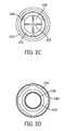
- FIG. 1Ctop view of the receptacle.
- FIG. 1Dis a perspective view of the receptacle.
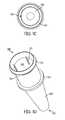
- FIGS. 2A-2Fare pictorial diagrams showing a cap of the present disclosure.
- FIG. 2Ais a side view of the cap.
- FIG. 2Bis a cross-sectional view of the cap taken along the line 2 B- 2 B in FIG. 2A .
- FIG. 2Ctop view of the cap.
- FIG. 2Dis a bottom view of the cap.
- FIGS. 2E and 2Fare top and bottom perspective views of the cap.
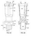
- FIG. 3Ais an exploded perspective view of the receptacle, the cap, and a portion of a receptacle transport mechanism configured to be inserted into the cap.
- FIG. 3Bis a side cross-sectional view of the cap installed in the receptacle.
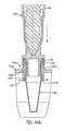
- FIG. 3Cis a longitudinal cross section of a cap and receptacle assembly embodying aspects of the present disclosure comprising an alternative embodiment of the cap.
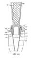
- FIG. 3Dis a longitudinal cross section of the cap and receptacle assembly of FIG. 3C , with the tip of a receptacle transport mechanism inserted into the cap.
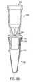
- FIG. 3Eis a perspective view, in longitudinal cross section, of a cap and receptacle assembly embodying aspects of the present disclosure and comprising an alternative embodiment of the cap with the tip of an receptacle transport mechanism inserted into the cap.
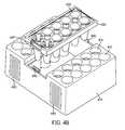
- FIG. 4Ais a perspective view of a multi-well tray for use in an automated reagent-based analyzer.
- FIG. 4Bis a perspective view of the multi-well tray with a card insert exploded from the multi-well tray.
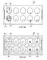
- FIGS. 5A-5Eare pictorial diagrams showing details of a card insert.
- FIGS. 5B-5Eshow various views of inner surfaces of the wells of the card insert.
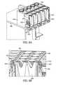
- FIGS. 6A and 6Bare pictorial diagrams showing attachment of the card insert to the base of the multi-well tray.
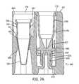
- FIGS. 7A and 7Bare cross-sectional views showing a cap and receptacle contained within the wells of the multi-well tray.
- FIG. 8is a pictorial diagram showing a cross-sectional view of an automated pipettor reconstituting a lyophilized reagent contained in a well of a multi-well tray.
- FIGS. 9A-9Eare pictorial diagrams showing alternative configurations of a multi-well tray and various exemplary embodiments of inner surfaces of the wells therein.
- FIGS. 10A and 10Bare pictorial diagrams showing perspective views of two cartridges with communicating wells.
- FIGS. 11A-11Dare pictorial diagrams showing a cartridge rack.
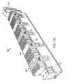
- FIG. 12is a partial top perspective view of a receptacle tray including features for separating an interlocked receptacle and cap, shown with a single receptacle-cap assembly held therein.
- FIG. 13is a partial bottom perspective view of the tray of FIG. 12 .
- FIGS. 14A , 14 B, 14 Cshow a sequence whereby a cap and receptacle, shown in cross section, are separated from one another using the tray of FIGS. 12 and 13 .
- the present disclosurerelates to a system, apparatus, and method for automated processing of a sample receptacle holder that is adapted for use in an automated instrument capable of performing nucleic acid-based amplification assays. Also provided are methods for conducting automated, random-access temperature cycling processes using the same.
- reaction mixturerefers to a volume of fluid comprising one or more of a target-specific reagent, diluent for reconstituting a lyophilized reagent, one or more nucleotides, an enzyme, and a sample containing or suspected of containing a nucleic acid.
- a “sample” or a “test sample”refers to any substance suspected of containing a target organism or biological molecule, such as nucleic acid.
- the substancemay be, for example, an unprocessed clinical specimen, a buffered medium containing the specimen, a medium containing the specimen and lytic agents for releasing nucleic acid belonging to the target organism, or a medium containing nucleic acid derived from a target organism which has been isolated and/or purified in a reaction receptacle or on a reaction material or device.
- a sample or test samplemay comprise a product of a biological specimen, such as an amplified nucleic acid to be detected.
- biochemical assayrefers to a scientific investigative procedure for qualitatively assessing or quantitatively measuring the presence or amount or the functional activity of a target entity, such as, but not limited to, a biochemical substance, a cell, organic sample, or target nucleic acid sequence. Included in the term “biochemical assay” are nucleic acid amplification and heat denaturation (i.e., melting). Nucleic acid melting typically involves precise warming of a double stranded nucleic acid molecule to a temperature at which the two strands separate or “melt” apart. The melting process typically occurs at a temperature of about 50° C. to about 95° C.
- lyophilizationrefers to a dehydration process that is typically used to preserve a perishable material and/or facilitate transport thereof.
- condition for lyophilizationrefer to subjecting a liquid material and/or a vessel containing the liquid material to freezing conditions while reducing the surrounding pressure to allow the frozen water within the material to sublimate directly from the solid phase to the gas phase.
- freezing conditionsmay include cooling the material below the lowest temperature at which the solid and liquid phases thereof can coexist (known in the art as the “triple point”).
- the freezing temperaturesare between ⁇ 50° C. and ⁇ 80° C., however, one of skill in the art can determine the appropriate freezing temperature to lyophilize the reagent for use in the automated biochemical assay.
- the term “reconstituting”refers to the act of returning a lyophilized material to its liquid form.
- the termencompasses contacting a fluid, e.g., water or other suitable diluent, with a lyophilized reagent for sufficient time to allow the lyophilized reagent to absorb water, thereby forming a stabilized liquid reagent.
- a receptacle 100to receive and store fluid test samples for subsequent analysis, including analysis with nucleic acid-based assays or immunoassays diagnostic for a particular pathogenic organism.
- the receptacle 100is a single-piece receptacle that includes a body 105 having a generally cylindrical upper portion 110 and a tapered lower portion 120 .
- a laterally-extending flangeFormed on an outer surface of the body 105 is a laterally-extending flange, which, in the illustrated embodiment, comprises an annular ring 125 , which separates the upper and lower portions of the body.
- the upper portion 110 of the body 105has an open end 145 through which fluid samples are deposited or removed from the receptacle 100 .
- the tapered lower portion 120has a closed end 150 that may either be flat or rounded to provide optical communication with an optical system, for example, one or more optical fibers (not shown) of a biochemical analyzer.
- the bottom surface of the closed-ended lower portionmay be flat or curved.
- the receptacle 100 optionally containing a sample or reaction mixtureis configured for insertion into a receptacle holder of an automated biochemical analyzer (not shown).
- a receptacle that is “configured for insertion”refers to the exterior surface of the body 105 of the receptacle 100 being sized and shaped to maximize contact between the receptacle and a receptacle well of a receptacle holder.
- this maximal contactrefers to physical contact of the receptacle well with at least a portion of the receptacle 100 .
- this maximal contactrefers to physical contact of the receptacle well with the tapered lower portion 120 of the receptacle 100 , or at least a portion the tapered lower portion 120 of the receptacle 100 .
- a plurality (i.e., 2, 3, 4, 5, 6, 7, or 8) of longitudinally oriented groovesmay be formed in the inner surface 140 of the upper portion 110 , and the grooves 135 may be equally spaced apart from one another around the entire circumference of the body 105 .
- Circumscribing the open end 145 of the upper portion 110 of the body 105is a lip 155 extending radially outward from a central axis thereof.
- the lip 155tapers from the outer-most portion of the radially-extended lip towards the open end of the body, and is configured for securable attachment to a cap 200 ( FIGS. 2A-2D ).
- the securable cap 200includes a lower portion 220 having an outer surface for sealing engagement of the inner surface 140 of the upper portion 110 of the receptacle 100 and an upper portion 210 .
- the outer surface of the lower portion 220 of the cap 200is formed with one or more annular ribs 230 for contacting the inner surface 140 of the upper portion 110 thereof.
- the lower portion 220 of the cap 200is formed with 1, 2, or 3 annular ribs 230 for contacting the inner surface 140 of the upper portion 110 of the receptacle 100 .
- the upper portion 210 of the cap 200includes an open end 215 for frictional attachment to a portion of a receptacle transport mechanism 300 ( FIG. 3A ), such as a tubular probe of a pipettor or pick-and-place robot. Guiding insertion of the receptacle transport mechanism 300 into the open end 215 of the upper portion 210 of the cap 200 are one or more linear ribs 260 formed in the inner surface 270 of the upper portion 210 . The linear ribs 260 protrude towards an axial center of the cap 200 , thereby decreasing the inner fitment diameter of the upper portion 210 of the cap 200 . Each linear rib 260 may be beveled (as at 262 ) at an upper, or proximal, end thereof.
- linear ribs 260can, among other things, enhance the frictional attachment to the receptacle transport mechanism 300 .
- 1, 2, 3, 4, 5, 6, 7, or 8 linear ribs 260are formed in the inner surface 270 of the cap 200 and extend at least a portion of the way down the length of the upper portion 210 thereof.
- At least one of the linear ribs 260may be formed with a portion 265 thereof, e.g., at a lower, or distal, end, that gradually tapers radially inward toward a central axis of the upper portion 210 of the cap.
- the amount of protrusion of the linear rib 260may gradually increase in size as the linear rib 260 approaches the bottom 245 of the upper portion 210 of the cap 200 .
- the linear rib 260may gradually increase in overall thickness as it approaches the bottom 245 of the upper portion 210 of the cap 200 .
- gradual increase in thickness or radial geometryis contemplated for the gradual tapering of the one or more linear ribs 260 , which serves to stabilize and center the receptacle transport mechanism 300 as it is lowered into the cap 200 for transport.
- each linear rib 260 and disposed on the exterior surface of the upper portion 210 of the cap 200are one or more indentations, or recesses, 234 that extend along at least part of the length thereof.
- the recessesmay be formed in any shape such as, for example, concave, notched, squared, etc.
- at least one recess 234is formed in the exterior surface of the upper portion 210 of the cap 200 .
- the length of the recess 234is the same as the length of the corresponding linear rib 260 , and each linear rib 260 is positioned such that it lies on the inner surface 270 of the cap 200 in a location that directly opposes the position of the at least one recess 234 formed on the outer surface of the cap 200 in a one-to-one relationship.
- the coupling of a linear rib 260 with an recess 234 in this mannerenhances the predictability of the frictional attachment of the cap 200 to a receptacle transport mechanism 300 .
- the receptacle transport mechanism 300as the receptacle transport mechanism 300 is lowered into the open end 215 of the cap 200 , it contacts the one or more linear ribs 260 , thereby pressing against the one or more linear ribs 260 .
- Such pressing against the linear ribs 260causes the cap 200 , and recesses 234 to flex and/or expand radially outward with respect to the axial center thereof to accommodate the receptacle transport mechanism 300 and thus enhance frictional attachment of the cap 300 to the receptacle transport mechanism 300 .
- 1, 2, 3, 4, 5, 6, 7, or 8 recesses 234may be formed on the exterior surface of the upper portion 210 of the cap 200 .
- Circumscribing the open end 215 of the upper portion 210 of the cap 200is a lip 225 extending radially outward from a central axis thereof.
- the lip 225tapers from the open end 215 towards the lower portion 220 .
- Protruding from the taper of the lip 225are a plurality of protrusions 235 .
- the protrusions 235may be equally spaced apart from one another and facilitate stacking and/or docking within a well of a multi-well tray 400 ( FIG. 4A ) for use in an automated biochemical analyzer.
- 1, 2, 3, 4, 5, 6, 7, or 8 protrusions 235are formed in the taper of the lip 225 .
- the cap 200is removed from the receptacle transport mechanism 300 by means of a sleeve 306 coaxially disposed over a tip of the receptacle transport mechanism 300 and axially movable with respect to thereto.
- the sleeve 306moves axially with respect to the tip toward a distal end of the tip and contacts the lip 225 of the cap, thereby pushing the cap off the tip of the receptacle transport mechanism 300 .
- the flange 240Separating the upper portion 210 from the lower portion 220 of the cap 200 is a flange 240 that extends radially away from an axial center thereof.
- the flange 240includes a plurality of locking arms 250 that extend from the flange 240 toward the lower portion 220 of the cap 200 .
- the locking arms 250are shaped for securely engaging the lip 155 of the receptacle 100 , and may be disposed to allow for removable attachment of the cap 200 to the receptacle 100 , while maintaining a leak-proof seal of the contents thereof.
- 1, 2, 3, 4, 5, 6, 7, or 8 locking arms 250are formed in the cap 200 .
- the flange 240 of the cap 200additionally serves to form a bottom 245 to separate the upper portion 210 from the lower portion 220 , thereby closing the interior of the receptacle 100 from the environment.
- the bottom 245is scored 255 for piercing by a mechanism for collecting and/or adding reagents to the test sample within the receptacle 100 . Such piercing avoids the need to remove the secured cap 200 from engagement with the receptacle 100 , while providing access to the contents therein.
- the receptacle 100 and cap 200 of the present disclosuremay be prepared from a number of different polymer and heteropolymer resins, including, but not limited to, polyolefins (e.g., high density polyethylene (“HDPE”), low density polyethylene (“LDPE”), a mixture of HDPE and LDPE, or polypropylene), polystyrene, high impact polystyrene and polycarbonate.
- polyolefinse.g., high density polyethylene (“HDPE”), low density polyethylene (“LDPE”), a mixture of HDPE and LDPE, or polypropylene
- polystyrenee.g., high density polyethylene (“HDPE”), low density polyethylene (“LDPE”), a mixture of HDPE and LDPE, or polypropylene
- polystyrenee.g., high density polyethylene (“HDPE”), low density polyethylene (“LDPE”), a mixture of HDPE and LDPE, or polypropylene
- An example of an HDPEis sold under the trade name Alathon M5370 and is available from Polymerland of Huntsville, N.C.; an example of an LDPE is sold under the trade name 722 and is available from The Dow Chemical Company of Midland, Mich.; and an example of a polypropylene is sold under the trade name Rexene 13T10ACS279 and is available from the Huntsman Corporation of Salt Lake City, Utah.
- LDPEis a softer, more malleable material than HDPE, the softness of LDPE provides flexibility in the locking arms 250 of the cap 200 to securably engage the lip 155 of the receptacle 100 .
- the receptacle 100 and cap 200may be comprised of a combination of resins, including, for example, a mixture of LDPE and HDPE, preferably in a mixture range of about 20% LDPE:80% HDPE to about 50% LDPE:50% HDPE by volume.
- the amounts of LDPE and HDPE used to form each of the receptacle 100 and cap 200may be the same or different.
- at least a portion of the cap 200is formed from an opaque material having low to no autofluorescence characteristics.
- the portion of the cap 200 formed from an opaque material having low to no autofluorescence characteristicsis at least the lower portion 220 thereof, including the inner surface 232 of the lower portion 220 of the cap 200 .
- the receptacle 100 and cap 200are preferably injection molded as unitary pieces using procedures well-known to those skilled in the art of injection molding, including a multi-gate process for facilitating uniform resin flow into the receptacle and cap cavities used to form the shapes thereof.
- Uniform resin flowis desirable for achieving consistency in thickness, which is important for a variety of reasons, including for the penetrable bottom 245 of the cap 200 ; to ensure a secure, such as an air-tight, engagement of the cap 200 and receptacle 100 ; to ensure a predictable engagement of the cap 200 with the receptacle transport mechanism 300 ; and to ensure maximal contact of the receptacle 100 with a receptacle well of a receptacle holder.
- the tip of a receptacle transport mechanism 300may include one or more annular ribs, as indicated at 302 and 304 , for enhancing a frictional, interference fit between the tip 300 and a component into which the tip 300 is inserted, such as the cap 200 or a pipette tip (not shown).
- a component into which the tip 300 is insertedsuch as the cap 200 or a pipette tip (not shown).
- the tip 300may be inserted into the cap and removed from the cap several times during the course of a process that is performed using the cap and a receptacle to which it is attached, such as a diagnostic assay.
- the capmay be made of a plastic material, such repeated insertion and removal of the tip 300 into and out of the cap may result in creep in the plastic material (permanent or semi-permanent deformation) that can result in a poor frictional connection between the tip 300 and the cap 200 .
- the capmay be provided with internal relief structures, or detents, that cooperatively engage one or both of the annular ribs 302 , 304 to enhance the securement of the cap to the tip.
- Cap 900includes an upper portion 910 , a lower portion 920 , an annular flange 940 with locking arms 950 extending axially therefrom, and an opening 915 that defines an inner-surface 970 .
- cap 900like cap 200 described above, is configured to engage a receptacle 100 by means of the locking arms 950 engaging the lip 155 surrounding the opening of the upper portion 110 of the receptacle 100 .
- the cap 900further includes a number of longitudinal ribs 960 extending axially along the inner surface 970 .
- the ribs 960are equiangularly spaced about the inner surface 970 .
- each rib 960has associated therewith a longitudinally-extending indention, or recess, 934 formed on an exterior surface of the upper portion 910 opposite the rib 960 .
- the recess 934may be in the form of a longitudinally extending, concave groove, which, in various embodiments, may be the same length as the rib 960 .
- Each rib 960includes an enlarged portion 965 at a lower distal end thereof.
- the rib 960includes a tapered transition between the upper narrower portion of the rib 960 and the larger lower portion 965 . Larger portion 965 may extend through a transition between the generally cylindrical inner surface 970 of the upper portion 910 and a tapered, e.g., conical, surface 972 .
- each rib 960 and associated recess 934cooperate to allow radial flexure of the rib 960 that enables the rib to conform to the general shape of a portion of a receptacle transfer mechanism inserted into the cap 900 .
- One or more of the longitudinal ribs 960further includes a relief, or detent, 964 defined as a portion of the enlarged section 965 of the rib 960 that is removed or scalloped out, as shown in FIG. 3C to define a concave recess or cavity in the lower end of the rib 960 .
- each relief 964receives the lower annular rib 302 of the receptacle transport mechanism 300 .
- the inter engagement of the annular rib 302 with the relief 964enhances the frictional securing of the cap 900 to the receptacle transport mechanism 300 .
- a detent 964is formed in every one of the longitudinal ribs 960 .
- Cap 1000includes an upper portion 1010 and a lower portion 1020 .
- An annular flange 1040extends radially from the cap 1000 and has a plurality of locking arms 1050 extending axially therefrom.
- cap 1000is configured to interlock with a receptacle 100 by means of the locking arms 1050 engaging a lip 155 surrounding an opening at the upper end 110 of the receptacle 100 .
- Cap 1000has a number of longitudinal ribs 1060 extending axially along an inner surface of the upper portion 1010 .
- the ribs 1060are equiangularly spaced about the inner surface of the upper portion.
- each rib 1060has associated therewith a longitudinally-extending indention or recess 1034 formed on an exterior surface of the upper portion 1010 opposite the rib 1060 .
- the recess 1034may be in the form of a longitudinally extending, concave groove, which, in various embodiments, may be the same length as the rib 1060 .
- each rib 1060transitions into an enlarged, portion 1065 near a lower, distal end thereof.
- Various embodimentsmay include a tapered transition between the enlarged portion 1065 and a non-enlarged portion of the rib 1060 .
- each rib 1060 and associated recess 1034cooperate to allow radial flexure of the rib 1060 that enables the rib to conform to the general shape of a portion of a receptacle transfer mechanism inserted into the cap 1000 .
- a relief, or detentis provided in one or more of the ribs 1060 by a window, or opening, 1064 cutout of the cap 1000 near the transition between the upper, relatively straight-sided surface 1070 and the lower, tapered portion 1072 of the upper portion 1010 .
- each opening 1064combined with the enlarged portion 1065 of the rib 1060 located directly above each opening 1064 , forms a relief or detent that receives the lower annular rib 302 of the receptacle transport mechanism 300 .
- an opening 1064is provided in each of at least two ribs 960 .
- two openings 1064are provided at diametrically opposed positions.
- the relief, or detent structure, provided by the opening 1064 of cap 1000 or the relief 964 or detent of cap 900physically engages a portion of the tip 300 , such as the annular rib 302 , to frictionally secure the cap 900 , 1000 on to the receptacle transport mechanism 300 with minimal or no deformation of the plastic material in the vicinity of the relief, thereby avoiding or limiting creep of the plastic material in the vicinity of the detent.
- cap-receptacle assemblyand its contents, such as, for example, centrifugation or incubation under isothermal or thermocycling conditions, it is necessary to access the interior of the receptacle to remove substances therefrom and/or to add substances thereto. Accordingly, in such instances, it becomes necessary to remove the cap 200 (or 900 or 100 ), from the receptacle 100 to which it is lockingly attached.
- a method for automated removal of a cap from a capped reaction receptacleincludes providing a receptacle 100 securably engaging the lip 155 of a receptacle 100 , as shown in FIG. 3B . Thereafter, performing an automated motion of contacting an inner portion 280 of at least one of the plurality of locking arms 250 of the cap 200 with a raised annular ridge defined around a receptacle slot.
- the receptacle slotmay be provided in a receptacle holder of an automated biochemical analyzer, alternatively the receptacle slot may be provided in a card or cartridge intended to be removed from an automated biochemical analyzer.
- the contactingurges the locking arms 250 away from the lip 155 of the receptacle 100 , thereby disengaging the cap 200 from the receptacle 100 .
- an automated motionis performed to lift the cap 200 away from the receptacle 100 , thereby removing the cap 200 from the receptacle 100 .
- the automated motionis performed by a receptacle transport mechanism 300 ( FIG. 3A ), such as, for example, a pipettor or pick-and-place robot.
- FIGS. 12 and 13are partial top and bottom perspective views, respectively, of a cap removal tray 1260 .
- the tray 1260includes a base 1262 generally surrounding the tray, and a top wall 1264 supported on the base 1262 .
- An assembly comprising the cap 200 and receptacle 100is shown inserted into one of the plurality of cap removal stations 1266 for removing the cap 200 from the receptacle 100 , as will be described below.
- the receptacle 100when inserted into an opening 1268 of the cap removal station 1266 , the receptacle 100 extends below the top wall 1264 .
- the base 1262has sufficient height to accommodate the length of the receptacle 100 projecting through the cap removal station 1266 and beneath the top wall 1264 .
- FIGS. 12 and 13which are partial views of the cap removal tray 1260 , a matrix of nine cap removal stations 1266 is shown.
- the cap removal tray 1260may have any number of cap removal stations 1266 .
- the cap removal stations 1266are oriented in aligned rows and columns. As will be described below, after the cap 200 is removed from the receptacle 100 , the receptacle 100 remains within the cap removal station 1266 .
- a spatially indexed orientationis provided so that a receptacle transport mechanism (e.g., an automated pipettor) can accurately identify and/or access any of the receptacles retained within the cap removal tray 1260 .
- a receptacle transport mechanisme.g., an automated pipettor
- Each cap removal stationincludes a raised collar 1270 surrounding the opening 1268 and extending above the top wall 1264 .
- a plurality of resilient tabs 1272e.g., four, surround the opening 1268 and extend below the top wall 1264 .
- each of the tabs 1272is angled radially inwardly relative to the center of the opening 1268 .
- FIGS. 14A , 14 B, 14 CThe manner in which a cap is removed from a receptacle by the cap removal station 1266 is shown by the sequence illustrated in FIGS. 14A , 14 B, 14 C.
- annular ring 125 formed on the receptacle 100engages the lower ends of the resilient tabs 1272 , which are angled inwardly so that the distance between the tabs at their lower or distal ends 1274 is less than the diameter of the annular ring 125 .
- the force of the annular ring 125 being pushed through the resilient tabs 1272pushes the tabs outwardly, as shown in FIG. 14A , to thereby permit the receptacle to be pushed through the tabs 1272 .
- the raised collar 1270has an outer surface that angles away from the opening 1268 with a larger width (e.g., diameter) at the base of the collar than at the tip of the collar and is configured so that the top edge of the raised collar 1270 will fit inside the undeflected locking arms 250 of the cap 200 to contact the an inner portion 280 (see FIG. 2B ) of the locking arms 250 .
- a larger widthe.g., diameter
- the lip 155 of the receptacle 100is spaced apart from the annular ring 125 of the receptacle 100 by a distance generally corresponding to the distance between the top edge, or upper tip, of the raised collar 1270 and the lower ends 1274 of the resilient tabs 1272 .
- the width, or diameter, of the upper edge of the raised collar 1270generally corresponds to the width, or diameter, of the lip 155 surrounding the opening of the receptacle.
- the annular ring 125 of the receptacle 100clears the lower ends 1274 of the resilient tabs 1272 .
- the receptacleis then essentially locked within the cap removal station 1266 , with the resilient tabs 1272 and the raised collar 1270 disposed between the lip 155 and the annular ring 125 .
- the contact between the underside of the lip 155 and the top edge of the raised collar 1270prevents the locking arms 250 from reengaging the lip 155 .
- cap 200when the cap 200 is then raised, its locking arms 250 are no longer engaged with the lip 155 of the receptacle 100 , and the receptacle 100 is retained within the cap removal station 1266 by the annular ring 125 in contact with the lower ends 1274 of the resilient tabs 972 .
- the cap 200can be separated from the receptacle 100 , and the receptacle 100 is retained within the cap removal station 1266 of the cap removal tray 1260 .
- cap removal stations 1266 of the cap removal tray 1260 and the cap 200 and receptacle 100are shown as having generally circular shapes, the concepts embodied in the cap removal stations 1266 are applicable to different shapes.
- a cap removal stationmay have a rectangular shape for remove a cap having similar a rectangular shape from a receptacle also having a similar rectangular shape.
- the cap removal tray 1260comprises an integrally-molded plastic component, and raised collar 1270 and resilient tabs 1272 of each cap removal station 1266 are integrally formed within the top wall 1264 .
- a multi-well tray 400for use in an automated process.
- a multi-well tray 400includes a base 410 having disposed in a top surface 417 thereof, a plurality of wells 415 , 416 .
- a card insert 420(see also FIG. 5A ) configured for removable attachment to the base 410 , is attached thereto.
- a top surface 425 of the card insert 420is substantially parallel to and flush with the top surface 417 of the base 410 .
- a plurality of wells 430Disposed in the top surface 425 of the card insert 420 , is a plurality of wells 430 , each configured for containing one or more reagents used for performing a biochemical analysis.
- Each well 430 of the card insert 420corresponds to at least one of the wells 415 disposed in the base 410 .
- the multi-well tray 400takes on the uniform appearance of, for example, a multi-well plate.
- the wells 415 , 416 disposed in the base 410may be arranged in pairs, where each pair corresponds to a single well 430 of the card insert 420 .
- the multi-well tray 400may include a plurality of sets 435 of wells, where each set 435 includes a first well 415 and a second well 416 , which are disposed in the top surface 417 of the base 410 , and a third well 430 disposed in the top surface 425 of the card insert 420 .
- the wells of each set 435 of wellsmay be in alignment with each other, thereby resulting in a multi-well tray 400 that is spatially indexed such than an automated receptacle transport mechanism 300 can accurately identify and/or access any of the plurality of wells when the multi-well tray 400 is placed or inserted into an automated system.
- the multi-well tray 400includes ten sets 435 of wells.
- the base 410is formed with ten pairs of first and second wells 415 , 416 and the card insert 420 is formed with ten third wells 430 , where each of the first, second, and third wells of the set 435 are arranged in alignment with each other.
- the multi-well tray 400may include ten receptacles 100 and ten caps 200 provided therein for used in an automated biochemical analyzer.
- the first and second wells 415 , 416 of the set 435are configured to receive a cap 200 and a receptacle 100 , respectively. While it should be understood that the terms “first” and “second” as used to distinguish the wells formed in the base 410 , for descriptive purposes, the “first well”, or cap well, 415 will refer to a well configured to receive a receptacle cap 200 .
- the first well 415 of the base 410is defined by a cylindrical wall 470 and a bottom wall 472 .
- a protrusion 475is sized and shaped for engagement, optionally frictional engagement, with a hollow portion 232 of the lower portion 220 of the cap 200 .
- the cylindrical wall 470may be formed with a plurality of tabs 477 protruding towards the axial center of the first well 415 .
- Such tabs 477are configured for securely engaging at least a portion of the cap 200 to prevent the cap 200 from dislodging from the multi-well tray if, for example, the multi-well tray is inverted or shaken.
- 2, 3, 4, 5, 6, 7, or 8 tabs 477are formed in the cylindrical wall 470 of the first well. Each of tabs 477 may securely engage the top surface of the flange 240 of the cap 200 .
- the “second well”, or receptacle well, 416will refer to a well configured to receive a receptacle 100 .
- the second well 416is defined by a cylindrical wall 480 and a bottom wall 482 .
- Formed in the center of the bottom wall 482is a through-hole 485 base.
- the through-hole 485is sized and shaped in conformance with the outer surface of the lower portion 120 of the receptacle 100 .
- the through-holemay be tapered at an angle corresponding to the angle of the lower portion 120 . As shown in FIG.
- the bottom wall 482 of the second well 416forms an annular ledge at the perimeter of the through-hole for engaging the ring 125 of the receptacle 100 .
- the cylindrical wall 480may be formed with a plurality of legs 487 protruding towards the axial center of the second well 416 .
- Such legs 487are configured for securely engaging at least a portion of the receptacle 100 to prevent the receptacle 100 from dislodging from the multi-well tray if, for example, the multi-well tray is inverted or shaken.
- 2, 3, 4, 5, 6, 7, or 8 legs 487are formed in the cylindrical wall 480 of the second well 416 .
- Each of the legs 487may securely engage the top surface of the ring 125 of the receptacle 100 .
- the third well, or reagent well, 430 of each set 435contains one or more reagents for performing a biochemical analysis.
- the third well 430 of the set 435contains a lyophilized reagent 495 ( FIGS. 8 and 9C ), and may be sealed with a frangible seal 440 ( FIG. 8 ).
- each well 430 of the card insert 420may be sealed with a metallic foil (or foil laminate) using, for example, a pressure sensitive adhesive which is applied to the top surface 425 thereof.
- the frangible seal 440may further include a plastic liner, such as a thin veneer of HDPE applied to one or both surfaces thereof, which promotes attachment of the frangible seal 440 to the top surface 425 when a heat sealer is used.
- Heat sealingis a well-known process and involves the generation of heat and the application of pressure to the surface being sealed, which, in this case, is the top surface 425 or a raised lip 427 (see FIGS. 4A , 5 A) surrounding the well 430 of the card insert 420 .
- any known ultrasonic welding procedure using either high frequency or high amplitude sound wavesmay also be used to affix the frangible seal 440 to the card insert 420 .
- the card insert 420may include a plurality of frangible seals 440 , each of which sealing a single well 430 , or may include a single sheet that seals all wells 430 disposed therein.
- a single lyophilized reagent 495may be provided in each well 430 of the card insert 420 .
- one or more wells 430 of the card insert 420may contain a different lyophilized reagent 495 , such as a different target-specific reagent.
- each well 430 of the card insert 420may contain a distinct lyophilized reagent 495 compared with the lyophilized reagent 495 contained in at least one other of the plurality of wells 430 therein.
- the card insert 420does not contain non-reagent consumables.
- a “reagent”refers to a substance or mixture for use in a chemical or biochemical reaction.
- non-reagent consumablerefers to a component that is used by an automated biochemical assay, but is not a reagent.
- exemplary non-reagent consumablesinclude, but are not limited to, contamination limiting elements, receptacles 100 , and caps 200 .
- each well 430 of the card insert 420is defined by a side wall, or well wall, 450 and a bottom, or bottom wall or bottom wall portion, 455 .
- the side wall 450tapers from an upper end thereof to the bottom 455 , and may therefore be referred to as a conical wall.
- the bottom 455 of each wellmay be formed with one or more features to facilitate deposit of and collection of fluid from the well. Such features include, but are not limited to a concave groove 457 , 460 ( FIGS.
- the featuresmay be located at the axial center of the well 430 , as shown in FIG. 5C , or may be off-set to a side thereof, as shown in FIG. 5B .
- the side wall 450may be formed with a plurality of bumps 462 on the surface thereof for additional facilitation of depositing and/or collecting fluids contained therein.
- the side wall 450 of each well 430 of the card insert 420may further be formed with a plurality of rigid guides 465 that protrude radially from the side wall 450 towards the axial center of the well 430 .
- Such rigid guides 465guide a pipette tip 310 ( FIGS. 8 and 9C ) mounted on an automated pipettor toward the axial center of the well 430 as the tip is lowered therein, and may further serve to retain the lyophilized reagent at, or adjacent to, the bottom 455 of the well 430 .
- each well 430may be independently formed with 2, 3, 4, 5, 6, 7, or 8 rigid guides 465 protruding from the respective tapered side wall 450 .
- the features formed at the bottom 455 of the well 430interfere with the end of a pipette tip inserted into the well 430 and thus prevent the end of the pipette tip from making sealing contact with the bottom 455 so as to prevent a negative pressure build up within the pipette tip during a fluid aspiration.
- a feature formed on the bottom 455 of well 430such as groove 457 , provides a clearance that prevents a pipette tip 310 from making sealing contact with the bottom 455 of the well 430 .
- each well 430 of the card insert 420may include one or more retention features ( FIGS. 8 , and 9 C- 9 D) that can be used to retain the lyophilized reagent 495 at, or adjacent to, the bottom 455 of the well 430 when, for example a diluent is deposited into the well 430 for reconstitution of a lyophilized reagent.
- FIGS. 9C and 9Dthe retention features are shown within a well 715 of an alternative embodiment of a multi-well tray 700 described below.
- the retention featuremay include one or more protrusions or an annular ridge 800 formed above the area to be occupied by the lyophilized reagent 495 , and extending toward the axial center of the well 430 .
- Such protrusions or annular ridge 800narrow the opening of the side wall 450 such that the opening is smaller than the diameter of the lyophilized reagent 495 .
- the annular ridge 800may be formed by inserting one or more heat stakes 880 into the wells 430 , such that the side wall 450 is deformed, thereby forming an annular ridge 800 therein.
- the one or more heat stakes 880may be attached to an apparatus 890 , which may heat the one or more heat stakes 880 , thereby providing sufficient heat to deform the side wall 450 at a point along the taper where the diameter thereof equals that of the diameter of the heat stake.
- the retention featuremay also take the form of one or more solid extensions 810 formed over the area to be occupied by the lyophilized reagent 495 .
- Such extensions 810connect opposing areas of the side wall 450 , thereby retaining the lyophilized reagent 495 at, or adjacent to, the bottom 455 of the well 430 .
- the side wall 450may be formed to mimic the thread of a coarse screw as shown at 820 .
- Such a threaded feature 820may be formed during injection molding of the well 430 , or may be formed by applying a heated screw portion to the well wall, thereby forming a spiral channel along a length thereof, through which fluid may run to the bottom 455 using gravitational force.
- the retention featuremay be provided in the form of a tapered ring insert 830 that is fixedly attached to the side wall 450 either before or after deposit of the lyophilized reagent 495 .
- the tapered ring 830may be formed of plastic and include an exterior surface that tapers in accordance with the taper of the side wall 450 . When present, the tapered ring 830 narrows the opening of the well 430 such that the lyophilized reagent 495 is retained at, or adjacent to, the bottom 455 of the well 430 .
- Whether the lyophilized bead 495 is formed within the well from an initially liquid reagent or the solid bead is formed outside the well and then placed into the wellmay depend on whether the retention feature is an integral part of the well. If the retention feature is an integral part of the well, a solid bead could not be placed into the well below the retention feature and a liquid reagent must be dispensed into the bottom of the well and then lyophilized. If the retention feature is not an integral part of the well, a lyophilized bead could be placed into the well, and then the retention feature installed in the well over the lyophilized bead.
- the inner surface of a well wallmay be substantially vertical as at 840 , while an exterior surface of the well retains its tapered shape.
- the inner surface of the well wallmay be substantially vertical as at 840 , while the exterior surface of the well is also substantially vertical (not shown).
- the vertical wall 840allows the entirety of a liquid reagent to be lyophilized to settle at the bottom 455 of the well, thereby ensuring reagent uniformity upon lyophilization.
- the retention featuremay be in the form of a capillary insert 850 that is fixedly attached to the well wall.
- the capillary insert 850may be formed of plastic and include an exterior surface that tapers in accordance with the taper of the well wall.
- the well and capillary insert 850may be formed as a single unit.
- the capillary insert 850may not extend completely to the bottom of the well, thereby defining a chamber 856 below a bottom end of the capillary insert 850 .
- the inner surface of the capillary insert 850may include substantially vertical walls forming a capillary channel 852 extending from an upper end of the insert to a lower end of the insert through which fluid will flow via capillary attraction, and within which the fluid will be retained as a result of the combination of surface tension and adhesive forces between the fluid and the walls of the capillary channel.
- the capillary insert 850may further include an open upper end 854 that tapers from a top surface of the insert 850 to the channel 852 .
- the lyophilized reagent 495After lyophilizing the liquid reagent, the lyophilized reagent 495 remains lodged within the channel 852 of the capillary insert 850 .
- Deposit of a diluent for reconstitution of the lyophilized reagent 495is accomplished by addition of the diluent to the tapered open upper end 854 of the capillary insert 850 .
- the diluentthen flows within the capillary channel 852 via capillary attraction, and is retained therein as a result of the combination of surface tension and adhesive forces between the diluent and the walls of the capillary channel 852 .
- the reagentmay be collected by insertion of the pipette tip 310 into the tapered open upper end 854 of the capillary insert 850 and withdrawing the liquid reagent therefrom.
- the entirety of the liquid reagentmay therefore be collected at the tapered open upper end 854 of the capillary insert 850 since the liquid will travel upwards due to capillary attraction within the channel 852 of the capillary insert 850 .
- the bottom 455 of the wellcan be formed to include a roughened surface, thereby providing sufficient surface area to which the lyophilized reagent 495 will adhere upon formation thereof.
- the lyophilized reagent 495will adhere to, or adjacent to, the bottom 455 of the well 430 through a static electrical attractive force created on the well wall 450 and/or bottom 455 of the well 430 .
- the inner surface of the well 430is provided with an electrical charge such that the lyophilized reagent 495 adheres thereto.
- the retention featuremay take the form of an insert through which the pipette tip 310 may be inserted.
- the retention featuremay be a fingered collar 860 that is fixedly attached to a top portion of the well.
- the fingered collar 860may be formed of plastic and include an exterior surface that tapers in accordance with the taper of the well wall.
- the fingered collar 860may include one or more (i.e., 1, 2, 3, 4, 5, 6, 7, or 8) fingers extending from a bottom surface thereof, and protruding along a radius of curvature toward the axial center of the well.
- the one or more fingersmay be flexible such that contact with a pipette tip 310 inserted therein causes the fingers to flex toward the well wall, thereby allowing the pipette tip 310 to pass there through. Upon withdrawal of the pipette tip 310 , the fingers return to a rest position such that the fingers protrude along the radius of curvature toward the axial center of the well.
- the retention featuremay take the form of a collar 870 that resembles the fingered collar 860 , but does not include the one or more fingers protruding therefrom.
- a collar 870may be fixedly attached to a top or center portion of the well wall, and may be formed of plastic and include an exterior surface that tapers in conformance with the taper of the well wall.
- the collar 870narrows the well wall to retain the lyophilized reagent 495 at, or adjacent to, the bottom 455 of the well, while allowing the pipette tip 310 to pass there through.
- Each of the base 410 and card insert 420may be independently constructed of an injection molded plastic, such as the plastics described above.
- the plastic used to form the base 410may be the same or different from the plastic used to form the card insert 420 .
- the card insert 420may be formed from a plastic having lower permeability to air and/or moisture than the plastic forming the base 410 .
- Such plasticsmay be more expensive than their conventional counterparts but, due to the decreased air and moisture permeability, provide for enhanced stability of reagents, such as lyophilized reagents contained in the wells thereof.
- any exterior surface of the base 410 or card insert 420may further include one or more identifying labels 490 , such as a barcode, 2D barcode, quick response (QR) code, radio frequency identification (RFID), or other human or machine readable indicia, disposed thereon.
- the information carried on such labelmay include identifying information regarding the multi-well tray 400 and/or card insert 420 , including information regarding the reagents contained therein, such as lot number, serial number, assay type, expiration date, etc.
- the base 410may include one or more barcodes and/or QR codes on a side surface thereof for identifying assays to be performed by the automated biochemical analyzer.
- the base 410may be formed with one or more locking arms 445 positioned for locking engagement with the card insert 420 .
- the card insert 420may be formed with one or more corresponding lock-holes 447 for receiving the locking arms 445 of the base 410 .
- the card insert 420is prevented from detachment therefrom.
- locking arms 445may be moved out of locking engagement with the card insert 420 to release the card insert 420 from the base 410 .
- Such releasable engagementprovides for reuse of the base 410 , if necessary, and/or replacement of a card insert 420 should the need arise.
- base 410may be further formed with one or more locking fingers 422 disposed on a side surface thereof.
- the locking fingers 422are configured for releasably engaging a rack to secure the base 410 to the rack for use in automated processing.
- the base 410may further include a release 437 for urging the locking fingers 422 away from the engaging surface of the rack to facilitate removal therefrom.
- the card insert 420may be secured to the base 410 by means of locking features 424 disposed along opposed sides of the card insert 420 that are configured for locking engagement with cooperating ledges 412 formed in the base 410
- FIGS. 9A-9Eshow an alternative embodiment of a multi-well tray 700 .
- the multi-well tray 700includes a base 710 having disposed in a top surface 717 thereof, a plurality of wells 715 .
- the base 710also includes an arm 720 for engagement by a transport mechanism, such as a rotary distributor (not shown) for transport within an automated biochemical analyzer.
- a transport mechanismsuch as a rotary distributor (not shown) for transport within an automated biochemical analyzer.
- the bottom surface 730 of the base 710is formed with one or more snap fingers 735 , which define a slot 740 into which an element (not shown) of the biochemical analyzer is inserted.
- snap fingers 735grasp the element (not shown) of the biochemical analyzer, thereby forming a secure attachment thereto.
- each well 715is configured to contain one or more reagents used for performing automated biochemical analysis. Similar to the wells 430 of the multi-well tray insert 420 , each well 715 is defined by an inner side wall 750 and a bottom 755 . In various embodiments, the side wall 750 tapers from a top portion of the well 715 to the bottom 755 , as shown in FIG. 9C .
- each well 715may be formed with one or more features to facilitate deposit of and collection of fluid from the well.
- Such featuresinclude, but not limited to a concave groove 457 , 460 ( FIGS. 5B-5D ), a convex ridge (not shown), or a set of grooves positioned in a crisscross pattern (not shown).
- the featuresmay be located at the axial center of the well 715 , as shown in FIG. 5C , or may be off-set to a side thereof, as shown in FIG. 5B .
- the inner wall 750may be formed with a plurality of bumps 462 ( FIGS.
- each well 715 of the card 700may further be formed with a plurality of rigid guides 465 ( FIG. 5B ) that protrude radially from the inner wall 750 towards the axial center of the well 715 .
- Such rigid guides 465guide the tip 310 ( FIGS. 8 and 9C ) mounted on an automated pipettor toward the axial center of the well 715 as the tip is lowered therein, and may further serve to retain the lyophilized reagent 495 at, or adjacent to, the bottom 755 of the well 715 .
- each well 715may be independently formed with 2, 3, 4, 5, 6, 7, or 8 rigid guides protruding from the respective tapered well wall 750 .
- each well 715 of the card 700may include one or more retention features 800 , 810 , 820 , 830 , 840 , 850 , 860 , 870 (FIGS. 8 and 9 C- 9 D), as described above, configured to retain the lyophilized reagent 495 at, or adjacent to, the bottom 755 of the well 715 when, for example a diluent is deposited into the well 715 for reconstitution.
- the retention featuresmay include an annular ridge 800 formed above the area to be occupied by the lyophilized reagent 495 , and extending toward the axial center of the well 715 .
- the retention featuresmay also take the form of one or more solid extensions 810 formed over the area to be occupied by the lyophilized reagent 495 .
- Such extensions 810connect opposing areas of the well wall 750 , thereby retaining the lyophilized reagent 495 at, or adjacent to, the bottom 755 of the well 715 .
- the well 715may include any of the various inserts 830 , 850 , 860 , or 870 , as discussed above.
- the well wall 750may be a vertical wall 840 or may be formed to include a screw thread (i.e., a spiral channel) 820 .
- the bottom 755 of the wellcan be formed to include a rough surface, thereby providing sufficient surface area to which the lyophilized reagent 495 will adhere upon formation thereof.
- the lyophilized reagent 495will adhere to the bottom 755 of the well 715 through a static electrical attractive force created on the well wall 750 and/or bottom 755 of the well 715 .
- FIGS. 10A and 10Bdepict different alternative cartridge embodiments.
- the cartridge 500includes a casing 510 having a top surface 517 , a fluid chamber 520 , and a fluid reservoir 515 .
- the fluid chamber 520 and the fluid reservoir 515comprise wells open at the top surface 517 .
- the fluid chamber 520has a smaller volumetric capacity than the fluid reservoir 515 .
- the perimeter of the open end of the fluid chamber 520may be smaller than the perimeter of the open end of the fluid reservoir 515 , and thus the exposed surface of a fluid in the fluid chamber 520 would be smaller than the exposed surface of a fluid in the fluid reservoir 515 .
- the fluid chamber 520 and the fluid reservoir 515may contain the same liquid, such as a diluent or a reconstitution solution for reconstituting the lyophilized reagent (e.g., lyophilized reagent 495 ).
- a diluentor a reconstitution solution for reconstituting the lyophilized reagent (e.g., lyophilized reagent 495 ).
- the cartridge 500may be provided with one or more fluid connections between the fluid chamber 520 and the fluid reservoir 515 .
- one or more openings 525 and/or 527 between the fluid chamber 520 and the fluid reservoir 515may include one or more channels between the fluid reservoir 515 and the fluid chamber 520 to provide a path through which a liquid or gas may flow between the fluid chamber 520 and the fluid reservoir 515 .
- An opening, such as opening 527 , between the fluid chamber 520 and the fluid reservoir 515may be provided by a slot or hole formed in a wall separating the fluid chamber 520 and the fluid reservoir 515 .
- a first opening 525is provided proximate a lower portion of the fluid chamber 520 and the fluid reservoir 515 (e.g., at a base of the casing 510 ) for fluid communication between the fluid chamber 520 and the fluid reservoir 515
- a second opening 527is provided proximate an upper end (i.e., near the open ends) of the fluid chamber 520 and the fluid reservoir 515 for fluid communication between the fluid chamber 520 and the fluid reservoir 515 .
- the cartridge 500may also include a second fluid reservoir 530 disposed within the casing and adjacent to the fluid chamber 520 .
- the second reservoir 530can be utilized to store the same or a different liquid than is stored in reservoir 515 .
- the second reservoir 530is not in fluid communication with the fluid reservoir 515 or the fluid chamber 520 .
- the fluid reservoir 515 and the fluid chamber 520contain a reconstitution solution, and the second reservoir 530 contains oil.
- each of the fluid chamber 520 , fluid reservoir 515 , and second reservoir 530may be sealed with a seal (not shown), such as a metallic foil (or foil laminate).
- a seal over the fluid reservoir 515 , the fluid chamber 520 , and/or the second reservoir 530may be provided to prevent spillage of fluid contents in case cartridge 500 is tipped, dropped, shaken, or inverted,
- the sealalso prevents or retards evaporation of the fluid contents of the sealed reservoir or chamber by preventing or limiting exposure to ambient atmosphere.
- the sealmay further include a plastic liner, such as a thin veneer of HDPE applied to one or both surfaces thereof.
- the sealmay be secured using, for example, a pressure sensitive adhesive or heat seal securing the foil to the top surface 517 securing the seal about the perimeter of the opening of each reservoir or chamber.
- a plastic linersuch as a thin veneer of HDPE applied to one or both surfaces of the seal, promotes attachment of the frangible seal to the top surface 517 when a heat sealer is used.
- the one or more openings ( 525 , 527 )may also be sealed with a frangible seal to prevent exposure to the ambient atmosphere
- the fluid reservoir 515 and the fluid chamber 520 and any connecting opening(s)are configured so that as fluid is removed from the fluid chamber 520 , replacement fluid flows into the fluid chamber 520 from the fluid reservoir 515 (e.g., through an opening 525 provided proximate a lower portion of the fluid chamber 520 and fluid reservoir 515 ).
- one or more conduitsmay be provided to permit air to flow into the fluid reservoir 515 (e.g., through an opening 527 provided proximate an upper portion of the fluid chamber 520 and fluid reservoir 515 ) as fluid is drawn out of the fluid reservoir 515 to thereby allow the pressure in the reservoir to equilibrate.
- the chamber 520is may be sealed with a frangible seal that is puncturable by a pipette tip.
- the entire volume of fluid in the fluid chamber 520 and the fluid reservoir 515is accessible to a fluid transfer apparatus, but a relatively small surface area of that fluid—e.g., corresponding to the width of the chamber 520 or to the size of a puncture hole formed in a seal over the chamber 520 —is exposed to air.
- a relatively small surface area of that fluide.g., corresponding to the width of the chamber 520 or to the size of a puncture hole formed in a seal over the chamber 520 —is exposed to air.
- the configuration of the cartridge 500retards evaporation of fluids contained therein.
- An amount of liquid, such as reconstitution solution,may be removed from the fluid chamber 520 within an automated pipettor and transferred to a well (e.g., well 430 or 715 ) to reconstitute a lyophilized reagent (e.g., lyophilized reagent 495 ), as described below.
- a welle.g., well 430 or 715
- a lyophilized reagente.g., lyophilized reagent 495
- the cartridge 500may be constructed of an injection molded plastic, such as the plastics described above. As discussed above, the plastic used to form the cartridge 500 may be one having low permeability to air and/or moisture.
- any exterior surface of the cartridge 500may further include one or more identifying labels, such as a barcode, 2D barcode, quick response (QR) code, radio frequency identification (RFID), or other human or machine readable indicia, disposed thereon.
- the information carried on such labelmay include identifying information regarding the cartridge 500 , including information regarding the liquids/reagents contained therein, such as lot number, serial number, assay type, expiration date, etc.
- the cartridge rack 600includes a chassis 610 and a handle 620 .
- a top surface 615 of the chassis 610is configured for releasable attachment of one or more multi-well trays 400 thereto, and therefore may include a plurality of locking members 625 for releasably engaging the locking fingers 422 of the multi-well tray 400 (see FIG. 6A ). While the FIG. 11B shows that two locking members 625 are provided for each multi-well tray 400 , it should be understood that the number of locking members 625 provided for each multi-well tray 400 will correspond with the number of locking fingers 422 provided on the multi-well tray 400 to be attached thereto.
- a plurality of identifying labelssuch as machine readable indicia 630 , such as a barcode, 2D barcode, quick response (QR) code, radio frequency identification (RFID), or other human or machine readable indicia, disposed thereon.
- the information carried on such labelmay include identifying information regarding the cartridge rack 600 , multi-well tray(s) 400 attached thereto, and/or the card insert(s) 420 attached to the multi-well tray(s) 400 , and/or the multi-well tray 400 position on the rack.
- the machine readable indicia 630may be readable through a direct contact connection, a wired connection, or a wireless connection between the cartridge rack 600 on the automated biochemical analyzer.
- the chassis 610is configured for releasable attachment of two or more multi-well trays 400 thereto, and may further be configured for releasable attachment to a cartridge with communicating wells 500 .
- five multi-well receptacles 400 and one cartridge 500may be releasably attached to the chassis 610 for use in an automated biochemical analyzer.
- 2, 3, 4, 5, 6, 7, or 8 multi-well trays 400 , and/or 1, 2, 3, or 4 cartridges 500may be attached to the chassis 610 .
- the present disclosureprovides a system for an automated reagent-based assay.
- the systemincludes a multi-well tray 400 that includes a plurality of wells 430 , a cartridge with communicating wells 500 , and an automated pipettor positioned on a robot arm (not shown).
- the systemincludes a housing within which each of the components are located.
- Each well 430 of the multi-well tray 400 shown and discussed abovecontains a lyophilized reagent 495 and is arranged in alignment with each other.
- the wells 430 of the multi-well tray 400may be sealed with a frangible seal.
- the multi-well tray 400may further include a plurality of additional wells 415 , 416 provided for receiving a receptacle 100 and a cap 200 .
- the additional wellsare positioned in aligned pairs, and the pairs are positioned in alignment with at least one well 430 containing a reagent, such as a lyophilized reagent 495 .
- the multi-well tray 400may contain a plurality of sets 435 of wells, where a first well 415 contains a cap 200 , a second well 416 contains a receptacle 100 , and a third well contains a reagent such as a lyophilized reagent 495 .
- the cartridge with communicating wells 500includes a casing 510 having a top surface 517 , a fluid chamber 520 .
- a first opening 527is provided in the top surface of the casing having at least one side wall surface extending to, or optionally forming at least a portion of, the fluid chamber.
- a fluid reservoir 515is disposed within the casing and in fluid communication with the fluid chamber.
- the cartridge 500will also include a second reservoir 530 that is disposed within the casing 510 and adjacent to the fluid chamber 520 .
- the automated pipettoris positioned on a robot arm contained in an automated biochemical analyzer.
- the automated pipettoris adapted to execute a retrieval and dispense protocol for conducting biochemical reactions.
- the retrieval and dispense protocolmay be performed by a controller (not shown) electrically connected to the robot arm and/or the automated pipettor to retrieve a portion of the reagent from the cartridge 500 and dispense the portion of the reagent into one or more wells of the multi-well tray 400 , 700 or into one or more receptacles.
- the retrieval and dispense protocolmay then be repeated for automated dispensing of the reagent into each of remaining wells of the multi-well tray 400 .
- the automated pipettorwill receive a command to perform automated actions required for performing an automated reagent-based assay.
- the automated pipettoris then moved by the robot arm to a position over an unused pipette tip 310 and is lowered to enable frictional attachment thereto.
- the robot armmoves the automated pipettor into a designated position over a cartridge 500 .
- the automated pipettoris thereafter lowered into the fluid chamber of the cartridge 500 .
- a frangible seal covering the fluid chamberis punctured by the pipette tip 310 .
- the automated pipettorthen withdraws a predetermined amount of diluent and is raised such that the pipette tip 310 is unobstructed by the cartridge 500 and/or other components within the automated biochemical analyzer.
- the robot armthen moves the automated pipettor into a designated position over a spatially indexed multi-well tray 400 and then lowers the pipettor such that the pipette tip 310 punctures a frangible seal 440 (if present) covering a well 430 disposed in the card insert 420 attached to the base 410 of the multi-well tray 400 .
- the diluentis then deposited into the well 430 containing a lyophilized reagent 495 used in the reagent-based assay.
- the automated pipettorwill repeatedly aspirate and the dispense the liquid contained in the well 430 to allow sufficient time and fluidic pressure required to reconstitute the lyophilized reagent 495 .
- the automated pipettorthereafter collects the reconstituted reagent and withdraws the pipette tip 310 from the well 430 of the multi-well tray 400 such that the pipette tip 310 is unobstructed by the well 430 and/or other components within the automated biochemical analyzer.
- the robot armthen moves the automated pipettor into a second designated position over the spatially indexed multi-well tray 400 .
- the second positionis selected in accordance with the set 435 of wells to which the well 430 of the card insert belongs.
- the automated pipettoris then lowered into a well 416 containing a receptacle 100 , which may or may not contain a sample undergoing analysis.
- the automated pipettorwill repeatedly aspirate and then dispense the liquid contained in the receptacle 100 to allow sufficient time and fluidic pressure required to mix the contents of the receptacle 100 within the well 416 , thereby creating a reaction mixture.
- the automated pipettorwithdraws the pipette tip 310 from the well 416 , but leaves the reaction mixture within the receptacle 100 .
- the robot armthen moves the automated pipettor to a location over a waste receptacle and ejects the pipette tip 310 .
- the robot armmoves the automated pipettor to a third designated position over the spatially indexed multi-well tray 400 .
- the third positionis selected in accordance with the set 435 of wells to which the first and second wells belong.
- the automated pipettoris then lowered into the third well 415 containing a cap 200 to enable frictional attachment thereto.
- the robot armmoves the automated pipettor into the second designated position over the well 416 containing the receptacle 100 containing the reaction mixture.
- the automated pipettoris then lowered such that the cap 200 is securably attached to the receptacle 100 as described above.
- the automated pipettorwithdraws from the well 416 , the capped receptacle attached thereto is withdrawn from the well 416 of the multi-well tray 400 for transport to, for example, a thermocycler for automated incubation.
- the automated pipettorwill receive a command to perform automated actions required for performing an automated reagent-based assay.
- the automated pipettoris then moved by the robot arm to a position over an unused pipette tip 310 , and is lowered to enable frictional attachment thereto.
- a transport mechanismsuch as a rotary distributor (not shown) within the biochemical analyzer attaches to an arm 720 of a multi-well tray 700 and transports the multi-well tray 700 to a predetermined position for use in the analysis.
- the robot armmoves the automated pipettor into a designated position over a cartridge 500 .
- the automated pipettoris thereafter lowered into the oil chamber 530 of the cartridge 500 . If present, a frangible seal covering the oil chamber 530 is punctured by the pipette tip 310 .
- the automated pipettorthen withdraws a predetermined amount of oil and is raised such that the pipette tip 310 is unobstructed by the cartridge 500 and/or other components within the automated biochemical analyzer.
- the robot armthen moves the automated pipettor into a designated position over a spatially indexed multi-well tray 400 and/or over a receptacle 100 , and the pipettor is lowered such that the pipette tip 310 enters the open end 145 thereof.
- the oilis then dispensed into the receptacle 100 .
- the procedure of withdrawing oil from the oil chamber 530 of the cartridge 500is repeated one or more times, depending on the number of reactions to be performed.
- the automated pipettorwithdraws the pipette tip 310 from the receptacle 100 , and the robot arm moves the automated pipettor to a location over a waste receptacle and ejects the pipette tip 310 .
- the robot armmoves the automated pipettor to a position over a second unused pipette tip 310 and lowers the pipettor to enable frictional attachment thereto.
- the robot armmoves the automated pipettor into a designated position over a second receptacle 100 having therein a sample for analysis, and is lowered such that the pipette tip 310 enters the open end 145 thereof.
- the sampleis then collected from the second receptacle and transferred to the first receptacle 100 .
- the samplewill have been previously dispensed into the receptacle prior to deposit of the oil and/or the sample for analysis may be transferred from a material transfer unit (not shown) within the biochemical analyzer.
- the automated pipettorwithdraws the pipette tip 310 from the receptacle 100 , and the robot arm moves the automated pipettor to a location over a waste receptacle and ejects the pipette tip 310 .
- the robot armmoves the automated pipettor to a position over a third unused pipette tip 310 and lowers the pipettor to enable frictional attachment thereto.
- the robot armmoves the automated pipettor into the second designated position over the cartridge 500 and lowers the pipettor into the fluid chamber 520 of the cartridge 500 . If present, a frangible seal covering the fluid chamber 520 is punctured by the pipette tip 310 .
- the automated pipettorthen withdraws a predetermined amount of diluent and is raised such that the pipette tip 310 is unobstructed by the cartridge 500 and/or other components within the automated biochemical analyzer.
- the robot armthen moves the automated pipettor into a designated position over a spatially indexed multi-well tray 700 and lowers the pipettor such that the pipette tip 310 punctures a frangible seal (if present) covering a well 715 disposed in the multi-well tray 700 .
- the diluentis then deposited into the well 715 containing a lyophilized reagent 495 used in the reagent-based assay.
- the automated pipettorwill repeatedly aspirate and dispense the liquid contained in the well 715 to allow sufficient time and fluidic pressure required to reconstitute the lyophilized reagent 495 .
- the automated pipettorthereafter collects the reconstituted reagent and withdraws the pipette tip 310 from the well 715 of the multi-well tray 700 such that the pipette tip 310 is unobstructed by the well 715 and/or other components within the automated biochemical analyzer.
- the robot armthen moves the automated pipettor into the designated position over the first receptacle 100 containing the dispensed oil and sample for analysis.
- the automated pipettoris then lowered into the open end 145 of the receptacle 100 to dispense the reconstituted reagent.
- the automated pipettorwill repeatedly aspirate and dispense the liquid contained in the receptacle 100 to allow sufficient time and fluidic pressure required to mix the contents of the receptacle 100 , thereby creating a reaction mixture.
- the automated pipettorwithdraws the pipette tip 310 from the receptacle 100 , but leaves the reaction mixture within the receptacle 100 .
- the robot armthen moves the automated pipettor to a location over the waste receptacle and ejects the pipette tip 310 .
- the robot armmoves the automated pipettor to a designated position over a well 415 containing a cap 200 to enable frictional attachment thereto.
- the robot armmoves the automated pipettor into the designated position over the receptacle 100 containing the reaction mixture.
- the automated pipettoris then lowered such that the cap 200 is securably attached to the receptacle 100 .
- the capped receptacleis lifted from a receptacle holder or well of a multi-well tray 400 for transport to, for example, a centrifuge and/or thermocycler for automated incubation.
- more than one robot arm and automated pipettormay be provided within the automated biochemical analyzer, and may be independently controlled to expand the capabilities thereof.
- the automated biochemical analyzermay include one or more pick and place robots, which may be used to perform functions not related to collection and/or deposit of liquids, such as capping of a receptacle 100 containing a reaction mixture and/or transport of the capped receptacle to a centrifuge and/or thermocycler for automated incubation.
Landscapes
- Chemical & Material Sciences (AREA)
- Health & Medical Sciences (AREA)
- Chemical Kinetics & Catalysis (AREA)
- Analytical Chemistry (AREA)
- General Health & Medical Sciences (AREA)
- Clinical Laboratory Science (AREA)
- Engineering & Computer Science (AREA)
- Hematology (AREA)
- Life Sciences & Earth Sciences (AREA)
- Mechanical Engineering (AREA)
- Biochemistry (AREA)
- Immunology (AREA)
- Physics & Mathematics (AREA)
- Pathology (AREA)
- General Physics & Mathematics (AREA)
- Medicinal Chemistry (AREA)
- Organic Chemistry (AREA)
- Ceramic Engineering (AREA)
- Proteomics, Peptides & Aminoacids (AREA)
- Wood Science & Technology (AREA)
- Zoology (AREA)
- Bioinformatics & Cheminformatics (AREA)
- Biophysics (AREA)
- Molecular Biology (AREA)
- Microbiology (AREA)
- Biotechnology (AREA)
- General Engineering & Computer Science (AREA)
- Genetics & Genomics (AREA)
- Robotics (AREA)
- Automatic Analysis And Handling Materials Therefor (AREA)
- Apparatus Associated With Microorganisms And Enzymes (AREA)
- Measuring Or Testing Involving Enzymes Or Micro-Organisms (AREA)
- Closures For Containers (AREA)
Abstract
Description
Claims (26)
Priority Applications (6)
| Application Number | Priority Date | Filing Date | Title |
|---|---|---|---|
| US14/210,163US9248449B2 (en) | 2013-03-14 | 2014-03-13 | Interlocking cap and receptacle with detent feature |
| US14/992,663US10159981B2 (en) | 2013-03-14 | 2016-01-11 | Plastic body configured for engagement with an automated receptacle transport mechanism |
| US16/127,837US11292003B2 (en) | 2013-03-14 | 2018-09-11 | Method and apparatus for separating interlocked cap and receptacle |
| US29/670,399USD857883S1 (en) | 2013-03-14 | 2018-11-15 | Receptacle |
| US16/238,239US11420207B2 (en) | 2013-03-14 | 2019-01-02 | Reaction receptacle |
| US17/709,362US20220219163A1 (en) | 2013-03-14 | 2022-03-30 | Cap having a ribbed inner surface |
Applications Claiming Priority (2)
| Application Number | Priority Date | Filing Date | Title |
|---|---|---|---|
| US201361782320P | 2013-03-14 | 2013-03-14 | |
| US14/210,163US9248449B2 (en) | 2013-03-14 | 2014-03-13 | Interlocking cap and receptacle with detent feature |
Related Child Applications (1)
| Application Number | Title | Priority Date | Filing Date |
|---|---|---|---|
| US14/992,663ContinuationUS10159981B2 (en) | 2013-03-14 | 2016-01-11 | Plastic body configured for engagement with an automated receptacle transport mechanism |
Publications (2)
| Publication Number | Publication Date |
|---|---|
| US20140260118A1 US20140260118A1 (en) | 2014-09-18 |
| US9248449B2true US9248449B2 (en) | 2016-02-02 |
Family
ID=50628976
Family Applications (21)
| Application Number | Title | Priority Date | Filing Date |
|---|---|---|---|
| US14/210,042ActiveUS9162228B2 (en) | 2013-03-14 | 2014-03-13 | Interlocking cap and receptacle for automated processes |
| US14/210,105Active2035-05-28US9718059B2 (en) | 2013-03-14 | 2014-03-13 | Multi-well tray and rack therefor |
| US14/210,127Active2035-08-06US10654041B2 (en) | 2013-03-14 | 2014-03-13 | Reagent wells containing lyophilized reagents |
| US14/210,163ActiveUS9248449B2 (en) | 2013-03-14 | 2014-03-13 | Interlocking cap and receptacle with detent feature |
| US14/210,182ActiveUS9527080B2 (en) | 2013-03-14 | 2014-03-13 | Fluid cartridge |
| US14/837,725Active2034-05-07US9630179B2 (en) | 2013-03-14 | 2015-08-27 | Fluid cartridge |
| US14/837,647ActiveUS9566582B2 (en) | 2013-03-14 | 2015-08-27 | Multi-well tray |
| US14/858,453AbandonedUS20160008810A1 (en) | 2013-03-14 | 2015-09-18 | Interlocking cap and receptacle for automated processes |
| US14/872,607AbandonedUS20160023211A1 (en) | 2013-03-14 | 2015-10-01 | Reagent well having a capillary insert |
| US14/992,663ActiveUS10159981B2 (en) | 2013-03-14 | 2016-01-11 | Plastic body configured for engagement with an automated receptacle transport mechanism |
| US15/339,347Active2034-09-29US10478820B2 (en) | 2013-03-14 | 2016-10-31 | Reagent well having a retention feature for retaining a lyophilized reagent |
| US15/430,726ActiveUS9817011B2 (en) | 2013-03-14 | 2017-02-13 | Method of using a multi-well tray |
| US15/604,791ActiveUS10065190B2 (en) | 2013-03-14 | 2017-05-25 | Multi-well tray and rack therefore |
| US15/677,364Active2034-04-26US11000851B2 (en) | 2013-03-14 | 2017-08-15 | Reagent well having a retention feature for retaining a lyophilized reagent |
| US16/115,152AbandonedUS20180361376A1 (en) | 2013-03-14 | 2018-08-28 | Reagent well having a capillary insert |
| US16/127,837Active2035-03-18US11292003B2 (en) | 2013-03-14 | 2018-09-11 | Method and apparatus for separating interlocked cap and receptacle |
| US29/670,399ActiveUSD857883S1 (en) | 2013-03-14 | 2018-11-15 | Receptacle |
| US16/238,239Active2035-05-25US11420207B2 (en) | 2013-03-14 | 2019-01-02 | Reaction receptacle |
| US29/751,799ActiveUSD977144S1 (en) | 2013-03-14 | 2020-09-23 | Cap for closing a vial |
| US29/751,800ActiveUSD952180S1 (en) | 2013-03-14 | 2020-09-23 | Cartridge |
| US17/709,362PendingUS20220219163A1 (en) | 2013-03-14 | 2022-03-30 | Cap having a ribbed inner surface |
Family Applications Before (3)
| Application Number | Title | Priority Date | Filing Date |
|---|---|---|---|
| US14/210,042ActiveUS9162228B2 (en) | 2013-03-14 | 2014-03-13 | Interlocking cap and receptacle for automated processes |
| US14/210,105Active2035-05-28US9718059B2 (en) | 2013-03-14 | 2014-03-13 | Multi-well tray and rack therefor |
| US14/210,127Active2035-08-06US10654041B2 (en) | 2013-03-14 | 2014-03-13 | Reagent wells containing lyophilized reagents |
Family Applications After (17)
| Application Number | Title | Priority Date | Filing Date |
|---|---|---|---|
| US14/210,182ActiveUS9527080B2 (en) | 2013-03-14 | 2014-03-13 | Fluid cartridge |
| US14/837,725Active2034-05-07US9630179B2 (en) | 2013-03-14 | 2015-08-27 | Fluid cartridge |
| US14/837,647ActiveUS9566582B2 (en) | 2013-03-14 | 2015-08-27 | Multi-well tray |
| US14/858,453AbandonedUS20160008810A1 (en) | 2013-03-14 | 2015-09-18 | Interlocking cap and receptacle for automated processes |
| US14/872,607AbandonedUS20160023211A1 (en) | 2013-03-14 | 2015-10-01 | Reagent well having a capillary insert |
| US14/992,663ActiveUS10159981B2 (en) | 2013-03-14 | 2016-01-11 | Plastic body configured for engagement with an automated receptacle transport mechanism |
| US15/339,347Active2034-09-29US10478820B2 (en) | 2013-03-14 | 2016-10-31 | Reagent well having a retention feature for retaining a lyophilized reagent |
| US15/430,726ActiveUS9817011B2 (en) | 2013-03-14 | 2017-02-13 | Method of using a multi-well tray |
| US15/604,791ActiveUS10065190B2 (en) | 2013-03-14 | 2017-05-25 | Multi-well tray and rack therefore |
| US15/677,364Active2034-04-26US11000851B2 (en) | 2013-03-14 | 2017-08-15 | Reagent well having a retention feature for retaining a lyophilized reagent |
| US16/115,152AbandonedUS20180361376A1 (en) | 2013-03-14 | 2018-08-28 | Reagent well having a capillary insert |
| US16/127,837Active2035-03-18US11292003B2 (en) | 2013-03-14 | 2018-09-11 | Method and apparatus for separating interlocked cap and receptacle |
| US29/670,399ActiveUSD857883S1 (en) | 2013-03-14 | 2018-11-15 | Receptacle |
| US16/238,239Active2035-05-25US11420207B2 (en) | 2013-03-14 | 2019-01-02 | Reaction receptacle |
| US29/751,799ActiveUSD977144S1 (en) | 2013-03-14 | 2020-09-23 | Cap for closing a vial |
| US29/751,800ActiveUSD952180S1 (en) | 2013-03-14 | 2020-09-23 | Cartridge |
| US17/709,362PendingUS20220219163A1 (en) | 2013-03-14 | 2022-03-30 | Cap having a ribbed inner surface |
Country Status (7)
| Country | Link |
|---|---|
| US (21) | US9162228B2 (en) |
| EP (3) | EP3885044A1 (en) |
| JP (10) | JP6171081B2 (en) |
| CN (7) | CN110038651B (en) |
| AU (9) | AU2013202778A1 (en) |
| CA (7) | CA2945126C (en) |
| WO (1) | WO2014151996A2 (en) |
Cited By (9)
| Publication number | Priority date | Publication date | Assignee | Title |
|---|---|---|---|---|
| US20160008810A1 (en)* | 2013-03-14 | 2016-01-14 | Gen-Probe Incorporated | Interlocking cap and receptacle for automated processes |
| WO2019014239A1 (en) | 2017-07-10 | 2019-01-17 | Gen-Probe Incorporated | Analytical systems and methods for nucleic acid amplification using sample assigning parameters |
| WO2019148169A1 (en) | 2018-01-29 | 2019-08-01 | Gen-Probe Incorporated | Analytical systems and methods |
| WO2020014400A1 (en) | 2018-07-10 | 2020-01-16 | Gen-Probe Incorporated | Methods and systems for detecting and quantifying nucleic acids |
| USD903898S1 (en) | 2018-09-24 | 2020-12-01 | Gentueri Inc. | Sampling assembly |
| US10889851B2 (en) | 2013-03-14 | 2021-01-12 | Gen-Probe Incorporated | Method for moving a processing vial between locations of an instrument |
| US20220143618A1 (en)* | 2019-04-12 | 2022-05-12 | Randox Laboratories Ltd | Assay Cartridge and Support Housing |
| US11471889B2 (en) | 2018-09-24 | 2022-10-18 | Gentueri Inc. | Sample assembly |
| US12442033B2 (en) | 2024-06-21 | 2025-10-14 | Gen-Probe Incorporated | Method for receiving and storing reagent packs in an instrument |
Families Citing this family (110)
| Publication number | Priority date | Publication date | Assignee | Title |
|---|---|---|---|---|
| US8448499B2 (en) | 2008-12-23 | 2013-05-28 | C A Casyso Ag | Cartridge device for a measuring system for measuring viscoelastic characteristics of a sample liquid, a corresponding measuring system, and a corresponding method |
| FI20116059A7 (en)* | 2011-10-28 | 2013-04-29 | Thermo Fisher Scientific Oy | Reagent bottle, system, method and device for handling closure caps and the like |
| US11865544B2 (en) | 2013-03-15 | 2024-01-09 | Becton, Dickinson And Company | Process tube and carrier tray |
| US10220392B2 (en) | 2013-03-15 | 2019-03-05 | Becton, Dickinson And Company | Process tube and carrier tray |
| CA2905204C (en) | 2013-03-15 | 2021-08-10 | Becton, Dickinson And Company | Process tube and carrier tray |
| USD762873S1 (en)* | 2013-03-15 | 2016-08-02 | Becton, Dickinson And Company | Process tube |
| US20150314295A1 (en)* | 2014-05-05 | 2015-11-05 | Mr1 Holdings, Llc | Sterile fluid handling device |
| US10661268B2 (en)* | 2014-06-30 | 2020-05-26 | Beacon Technologies, LLC | Pipette tip system, device and method of use |
| US9897618B2 (en) | 2014-09-29 | 2018-02-20 | C A Casyso Gmbh | Blood testing system |
| US10816559B2 (en) | 2014-09-29 | 2020-10-27 | Ca Casyso Ag | Blood testing system and method |
| US10175225B2 (en) | 2014-09-29 | 2019-01-08 | C A Casyso Ag | Blood testing system and method |
| US10288630B2 (en) | 2014-09-29 | 2019-05-14 | C A Casyso Gmbh | Blood testing system and method |
| US10539579B2 (en) | 2014-09-29 | 2020-01-21 | C A Casyso Gmbh | Blood testing system and method |
| WO2016073832A1 (en)* | 2014-11-07 | 2016-05-12 | Theranos, Inc. | Improved methods, devices, and systems for mixing fluids |
| WO2016130964A1 (en) | 2015-02-13 | 2016-08-18 | Abbott Laboratories | Decapping and capping apparatus, systems and methods for use in diagnostic analyzers |
| US9810622B2 (en) | 2015-04-09 | 2017-11-07 | Gen-Probe Incorporated | Sample testing systems and methods with automated cleaning |
| WO2016169678A1 (en)* | 2015-04-23 | 2016-10-27 | Aj Innuscreen Gmbh | Device and method for extracting nucleic acids |
| EP3088306A1 (en)* | 2015-04-27 | 2016-11-02 | Roche Diagniostics GmbH | Recapper, laboratory automation system and method of recapping a sample container |
| WO2017008228A1 (en) | 2015-07-13 | 2017-01-19 | Coyote Bioscience Co., Ltd. | Device and method for sample collection |
| TW201703754A (en)* | 2015-05-25 | 2017-02-01 | 卡尤迪生物科技(北京)有限公司 | Devices and methods for sample collection |
| USD777343S1 (en)* | 2015-05-28 | 2017-01-24 | C A Casyso Ag | Body fluid cartridge device |
| WO2016200933A1 (en) | 2015-06-09 | 2016-12-15 | Gen-Probe Incorporated | Methods and devices for calibrating and/or monitoring optical measurement devices |
| US10295554B2 (en) | 2015-06-29 | 2019-05-21 | C A Casyso Gmbh | Blood testing system and method |
| EP3332200B1 (en) | 2015-08-03 | 2021-10-06 | Gen-Probe Incorporated | Apparatus for maintaining a controlled environment |
| US11781811B2 (en)* | 2015-08-03 | 2023-10-10 | Gen-Probe Incorporated | Apparatus for maintaining a controlled environment |
| USD810959S1 (en)* | 2015-09-29 | 2018-02-20 | Bd Kiestra B.V. | Cuvette tray |
| US10331586B2 (en)* | 2015-10-30 | 2019-06-25 | Samsung Electronics Co., Ltd. | Nonvolatile memory device for providing fast booting and system including the same |
| ES2920382T3 (en) | 2015-11-16 | 2022-08-03 | Beckman Coulter Inc | Sample tube rack and sample tube analysis system |
| EP3387107B1 (en)* | 2015-12-11 | 2020-08-12 | Spartan Bioscience Inc. | Tube sealing system and methods for nucleic acid amplification |
| KR101764300B1 (en)* | 2015-12-24 | 2017-08-04 | 바디텍메드(주) | Reagent cartridge having a cone-type injection opening |
| US10648018B2 (en)* | 2016-03-15 | 2020-05-12 | Abbott Molecular Inc | Reaction vessel systems and methods and systems for using same |
| EP3442710B1 (en) | 2016-04-14 | 2024-11-13 | Gen-Probe Incorporated | Assemblies for storing sample processing consumables and sample processing instruments |
| WO2017210515A1 (en) | 2016-06-03 | 2017-12-07 | Advanced Instruments, Llc | Plug for osmometry sample cup |
| USD812243S1 (en) | 2016-07-28 | 2018-03-06 | Beckman Coulter, Inc. | Sample tube rack |
| USD808540S1 (en) | 2016-07-28 | 2018-01-23 | Beckman Coulter, Inc. | Sample tube rack |
| US10473674B2 (en) | 2016-08-31 | 2019-11-12 | C A Casyso Gmbh | Controlled blood delivery to mixing chamber of a blood testing cartridge |
| EP3300803B1 (en)* | 2016-09-30 | 2019-05-15 | F. Hoffmann-La Roche AG | Analytical system with accurate positioning of multiwell plates |
| JP7013804B2 (en) | 2016-12-15 | 2022-02-01 | 株式会社リコー | Container and calibration standard plate |
| EP4026617B1 (en) | 2017-03-21 | 2024-01-03 | Gen-Probe Incorporated | Fluid receptacles |
| FR3065532B1 (en)* | 2017-04-20 | 2020-07-17 | Diagnostica Stago | BALL CONDITIONING DEVICE FOR REACTION CELLS FOR AN ANALYZING APPARATUS |
| CN110603098A (en) | 2017-05-02 | 2019-12-20 | 格莱恩比奥-奥内有限公司 | Extraction assembly or test tube with an extension element for small amounts of body fluid |
| CN110612343B (en)* | 2017-05-12 | 2023-02-17 | 环球生物研究株式会社 | Nucleic acid detection cartridge |
| US10137447B1 (en) | 2017-05-17 | 2018-11-27 | Biotix, Inc. | Ergonomic fluid handling tubes |
| JP6831539B2 (en)* | 2017-05-22 | 2021-02-17 | 栄研化学株式会社 | Reagent cartridge |
| CN113680404B (en) | 2017-06-08 | 2023-01-31 | 因特格拉生物科学有限公司 | Disposable memory liner and kit |
| CN206798151U (en)* | 2017-06-08 | 2017-12-26 | 京东方科技集团股份有限公司 | Lid operation instrument and cover combination structure |
| USD938612S1 (en) | 2017-06-16 | 2021-12-14 | Beckman Coulter, Inc. | Sample rack |
| WO2018232364A1 (en) | 2017-06-16 | 2018-12-20 | Beckman Coulter, Inc. | Apparatus and method for handling sample containers |
| US10843185B2 (en) | 2017-07-12 | 2020-11-24 | Ca Casyso Gmbh | Autoplatelet cartridge device |
| EP3658885A4 (en)* | 2017-07-27 | 2021-09-22 | Biomerieux, Inc | INSULATING PIPE |
| US10117615B1 (en)* | 2017-08-01 | 2018-11-06 | Nova Biomedical Corporation | Analyzer cartridge with capillary wiper |
| JP6972835B2 (en)* | 2017-09-25 | 2021-11-24 | 株式会社Jvcケンウッド | Dispensing unit |
| CA3076836A1 (en) | 2017-09-27 | 2019-04-04 | Axxin Pty Ltd | Diagnostic test system and method |
| EP3474010B1 (en)* | 2017-10-19 | 2020-06-24 | Biotage AB | Chromatography cartridge seal arrangement |
| US20190119011A1 (en)* | 2017-10-21 | 2019-04-25 | Zipporo LLC | Sealable Container System |
| US12103007B2 (en) | 2017-10-23 | 2024-10-01 | Roche Molecular Systems, Inc. | Base module and tray insert of a multipurpose tray for an automated processing system, multipurpose tray for an automated processing system, and method of simplified loading/unloading of a multipurpose tray into/from an automated processing system |
| USD882113S1 (en)* | 2017-11-30 | 2020-04-21 | Biotix, Inc. | Fluid handling tube |
| JP7033449B2 (en)* | 2017-12-26 | 2022-03-10 | 川崎重工業株式会社 | Dispensing robot, control method and dispensing method of dispensing robot |
| USD927685S1 (en)* | 2018-01-18 | 2021-08-10 | Gen-Probe Incorporated | Receptacle |
| USD881410S1 (en)* | 2018-01-19 | 2020-04-14 | Biotix, Inc. | Fluid handling tube |
| CN108196081A (en)* | 2018-01-23 | 2018-06-22 | 深圳市国赛生物技术有限公司 | A kind of POCT specific proteins analysis system |
| JP6481187B1 (en)* | 2018-02-05 | 2019-03-13 | エイブル株式会社 | Sample measurement method, multi-well plate lid, sample measurement kit, and sample measurement apparatus |
| JP6539774B1 (en)* | 2018-05-11 | 2019-07-03 | バイオティクス, インコーポレイテッド | Pipette tip |
| USD905865S1 (en) | 2018-05-11 | 2020-12-22 | Biotix, Inc. | Pipette tip |
| CA3226075A1 (en)* | 2018-07-10 | 2020-01-16 | Biolyph, Llc | Reagent storage devices and methods for same |
| US11117129B2 (en) | 2018-08-17 | 2021-09-14 | Life Technologies Corporation | System and method for preparation of nucleotide solutions |
| USD922611S1 (en) | 2018-08-22 | 2021-06-15 | Quest Diagnostics Investments Llc | Plate for a sampling apparatus |
| WO2020041512A1 (en) | 2018-08-22 | 2020-02-27 | Quest Diagnostics Investments Llc | Plate for sampling apparatus and microcentrifuge vial for microsampling apparatus |
| USD902429S1 (en)* | 2018-08-22 | 2020-11-17 | Quest Diagnostics Investments Llc | Vial for sampling assembly |
| US20210339259A1 (en)* | 2018-08-29 | 2021-11-04 | Biotix, Inc. | Pipette tip rack assemblies |
| WO2020086573A1 (en)* | 2018-10-22 | 2020-04-30 | Kimantech, Llc | Loading devices and systems |
| CN111172008B (en) | 2018-11-09 | 2021-09-28 | 开启基因股份有限公司 | Method and device for automatic nucleic acid extraction |
| CN117680210A (en) | 2018-12-07 | 2024-03-12 | 元素生物科学公司 | Flow cell devices, cartridges and systems |
| CN109569761B (en)* | 2018-12-14 | 2021-02-19 | 重庆大学附属肿瘤医院 | Adjustable blood sampling tube rack and use method thereof |
| AU201817586S (en)* | 2018-12-17 | 2019-01-21 | Leica Biosystems Melbourne Pty | A reagent container |
| USD977610S1 (en)* | 2019-03-19 | 2023-02-07 | Soclean Inc. | Filter cartridge |
| CN118164173A (en) | 2019-05-03 | 2024-06-11 | 简·探针公司 | Container transport system for an analysis system |
| IL289549B1 (en)* | 2019-07-02 | 2025-07-01 | Beijing Sightnovo Medical Tech Co Ltd | Reagent holder, testing apparatus assembly, aqueous humor collection device and aqueous humor collection method |
| US20220372417A1 (en)* | 2019-10-30 | 2022-11-24 | Agilent Technologies, Inc. | Methods and apparatus for cell culture wellplates |
| CN112916057A (en)* | 2019-12-06 | 2021-06-08 | 青岛益柏生物科技有限公司 | Liquid sample processing container |
| FR3106764B1 (en)* | 2020-01-31 | 2022-04-29 | Letat Francais Represente Par Le Mini De Linterieur | Device for analyzing biological solid elements and device for its implementation |
| USD975312S1 (en) | 2020-02-14 | 2023-01-10 | Beckman Coulter, Inc. | Reagent cartridge |
| US11732964B2 (en) | 2020-04-15 | 2023-08-22 | Navinta Iii Inc | Lyophilization promoting element |
| FR3110696B1 (en)* | 2020-05-20 | 2024-08-23 | Letat Francais Represente Pr Le Mini De Linterieur | Sampling box and modular automaton including this sampling box |
| TWI712451B (en) | 2020-07-03 | 2020-12-11 | 思創影像科技股份有限公司 | Tip adaptor, biological detection device and biological detection method |
| WO2022025920A1 (en)* | 2020-07-31 | 2022-02-03 | Hamilton Company | Pipetting device, pipette tip coupler, and pipette tip: devices and methods |
| EP4241060A4 (en)* | 2020-10-09 | 2024-12-04 | Mingfu Ling | SAMPLE TRANSPORT MEDIUM PIPE |
| CN116648307A (en)* | 2020-10-19 | 2023-08-25 | 有劲健康加拿大公司 | Apparatus, system and method for processing laboratory ware |
| EP4252908A4 (en)* | 2020-12-07 | 2025-02-19 | Bioneer Corporation | ADAPTER FOR MOUNTING A CONDUCTIVE PIPETTE, DEVICE FOR OPENING/CLOSING SAMPLE TUBES, AND AUTOMATIC SAMPLE ANALYSIS SYSTEM |
| USD1058806S1 (en)* | 2020-12-23 | 2025-01-21 | Cytena Gmbh | Cartridge |
| CN116963673A (en)* | 2021-03-05 | 2023-10-27 | 贝克顿·迪金森公司 | Small-volume collection container |
| USD989343S1 (en)* | 2021-03-11 | 2023-06-13 | Lujia Gao | Sample vial with a lid |
| USD1003416S1 (en)* | 2021-05-13 | 2023-10-31 | Beyond Air, Inc. | Filter cartridge |
| TW202332504A (en)* | 2021-05-28 | 2023-08-16 | 美商梅梭刻度技術公司 | Devices and method for multi-well plate liquid distribution |
| KR102340376B1 (en)* | 2021-06-10 | 2021-12-17 | 대한민국 | Desiccator |
| WO2023279273A1 (en)* | 2021-07-07 | 2023-01-12 | 张静文 | Cup lid |
| EP4414712A3 (en) | 2021-07-29 | 2024-08-28 | Gen-Probe Incorporated | Automated systems and methods for loading solid reagent pellets into wells of a cartridge |
| US12226776B2 (en) | 2021-11-04 | 2025-02-18 | Instrumentation Laboratory Company | Preparing substances in a medical diagnostic system |
| WO2023192125A1 (en)* | 2022-03-30 | 2023-10-05 | Illumina, Inc. | Well assemblies and related systems and methods |
| USD979093S1 (en) | 2022-05-05 | 2023-02-21 | Singular Genomics Systems, Inc. | Reagent cartridge |
| USD981591S1 (en) | 2022-05-05 | 2023-03-21 | Singular Genomics Systems, Inc. | Sample cartridge |
| USD970036S1 (en) | 2022-05-05 | 2022-11-15 | Singular Genomics Systems, Inc. | Reagent cartridge |
| LU102954B1 (en)* | 2022-05-20 | 2023-12-01 | Stratec Se | Device for sealing of a reagent container |
| EP4548108A1 (en)* | 2022-06-30 | 2025-05-07 | Illumina, Inc. | Hydration and homogenization of lyophilized reagents |
| EP4299457A1 (en)* | 2022-07-01 | 2024-01-03 | Kiro Grifols, S.L. | Machine for the preparation of medical product with removable device for loading medical containers |
| USD1049418S1 (en)* | 2022-12-08 | 2024-10-29 | Eppendorf Se | Handoperated instrument and tool for laboratories |
| US20250306052A1 (en)* | 2022-12-23 | 2025-10-02 | Illumina, Inc. | Apparatus and method for transferring and delivering dried reagents |
| US20240337674A1 (en)* | 2023-04-04 | 2024-10-10 | FIALab Insruments Inc. | Sequential injection analysis system and method for mixing fluids |
| USD1069156S1 (en) | 2023-04-10 | 2025-04-01 | Becton, Dickinson And Company | Dispensing device |
| WO2024243642A1 (en)* | 2023-06-02 | 2024-12-05 | Vitrafy Life Sciences Limited | Packaging for preservation of biological material |
Citations (21)
| Publication number | Priority date | Publication date | Assignee | Title |
|---|---|---|---|---|
| EP0488769A2 (en) | 1990-11-29 | 1992-06-03 | The Perkin-Elmer Corporation | Thermal cycler for automatic performance of the polymerase chain reaction with close temperature control |
| US5119560A (en) | 1991-01-07 | 1992-06-09 | Apothecary Products, Inc. | Medicine dosage device |
| US5846489A (en) | 1994-04-09 | 1998-12-08 | Boehringer Mannheim Gmbh | System for opening closures of vessels and for the contamination-free operation of reaction sequences |
| US5863791A (en) | 1996-07-11 | 1999-01-26 | Eppendorf-Netheler-Hinz Gmbh | Cover receptacle assembly |
| US6216340B1 (en) | 1997-10-02 | 2001-04-17 | Roche Diagnostics Corporation | Automatic handling of sample cups closed with a screwable cap |
| US6312886B1 (en) | 1996-12-06 | 2001-11-06 | The Secretary Of State For Defence In Her Brittanic Majesty's Government Of The United Kingdom Of Great Britain And Northern Ireland | Reaction vessels |
| US6455325B1 (en) | 1995-03-20 | 2002-09-24 | Precision System Science Co., Ltd. | Liquid processing method making use of pipette device and apparatus for same |
| US20030162285A1 (en) | 2000-06-30 | 2003-08-28 | Hideji Tajima | Reaction vessel, reaction device and temperature control method for reaction liquid |
| US20050123457A1 (en) | 2001-07-06 | 2005-06-09 | Precision System Science Co., Ltd. | Reaction vessel and reaction apparatus |
| USD511214S1 (en) | 2003-11-21 | 2005-11-01 | Saika Technological Institute Foundation | Cartridge for extraction of solids for chromatography analysis |
| US20060014272A1 (en) | 2002-06-17 | 2006-01-19 | Precision System Science Co., Ltd. | Reaction vessel and reaction product extracting apparatus |
| US20080072690A1 (en) | 2001-03-09 | 2008-03-27 | Gen-Probe Incorporated | Penetrable cap |
| US20080268529A1 (en) | 2004-06-02 | 2008-10-30 | Arkray, Inc. | Container for Nucleic Acid Amplification, Nucleic Acid Preparation Kit and Nucleic Acid Analyzer |
| USD583058S1 (en) | 2008-01-23 | 2008-12-16 | Short David A | Kidney stone collection device |
| EP2030687A1 (en) | 2007-08-13 | 2009-03-04 | Hamilton Bonaduz AG | Locking device with snap mechanism |
| US7550291B2 (en) | 2003-03-05 | 2009-06-23 | Roche Molecular Systems, Inc. | Vessel system for the treatment and/or storage of liquids |
| US20100224632A1 (en) | 2005-11-30 | 2010-09-09 | Antoine Aneas | Plug Device for a Container and Container Provided With One Such Device |
| US20100264155A1 (en) | 2009-04-15 | 2010-10-21 | Spartan Bioscience, Inc | Tube for dna reactions |
| US7951336B2 (en) | 2004-08-05 | 2011-05-31 | Universal Bio Research Co., Ltd. | Reaction vessel, reaction vessel liquid introducing device, liquid introducing and reaction measuring device, and liquid introducing device |
| WO2012173919A1 (en) | 2011-06-14 | 2012-12-20 | 3M Innovative Properties Company | Method of processing a sample for analysis |
| US20140263153A1 (en) | 2013-03-14 | 2014-09-18 | Gen-Probe Incorporated | Interlocking cap and receptacle for automated processes |
Family Cites Families (204)
| Publication number | Priority date | Publication date | Assignee | Title |
|---|---|---|---|---|
| BE533852A (en) | ||||
| CA147906A (en)* | 1913-01-21 | 1913-05-13 | Senzo Yasaki | Brooom head |
| GB483046A (en) | 1936-10-07 | 1938-04-07 | Henry O Day Morrison | A method of removing crown corks from glass metal or like containers |
| US3027799A (en)* | 1959-01-26 | 1962-04-03 | Brunswick Corp | Sample space adapters for spectrophotometers and the like |
| US3005564A (en)* | 1959-10-12 | 1961-10-24 | Biolog Res Inc | Laboratory equipment |
| FR1404672A (en) | 1964-04-17 | 1965-07-02 | Bouchage Mecanique | Pipette spreader cap |
| US3498470A (en)* | 1967-11-02 | 1970-03-03 | Burger Chef Systems Inc | Serving tray with integral cup holder |
| US3477822A (en)* | 1967-12-26 | 1969-11-11 | Xerox Corp | Chemical package |
| CH493834A (en)* | 1968-05-02 | 1970-07-15 | Eppendorf Geraetebau Netheler | Plastic reaction vessel for the photometric investigation of small amounts of liquid |
| US3653528A (en)* | 1970-03-03 | 1972-04-04 | West Co | Stopper for medicament flasks |
| US3785773A (en)* | 1972-03-02 | 1974-01-15 | Beckman Instruments Inc | Chemical analysis tube module |
| DE2333434C3 (en)* | 1973-06-30 | 1978-04-06 | Istvan D. Dr. 5024 Pulheim Bartos | Process for carrying out serological tests according to the principle of the complement fixation reaction and ready-to-use rapid test pack for this |
| CA1035260A (en) | 1974-08-12 | 1978-07-25 | Baxter Travenol Laboratories | Collection and processing tube |
| JPS5946873B2 (en)* | 1977-07-08 | 1984-11-15 | 凸版印刷株式会社 | Cap attachment/detachment device |
| DE2806089A1 (en)* | 1978-02-14 | 1979-08-16 | Heraeus Christ Gmbh | Combined inner and outer container for biological fluids - has inner container lead welded to outer container sleeve |
| CH645820A5 (en) | 1979-05-26 | 1984-10-31 | Hoffmann La Roche | SAMPLE OR REAGENT TANK. |
| US4338936A (en)* | 1980-10-27 | 1982-07-13 | Byron Nelson | Device and method for delivering solid medication to an eye |
| JPS59174758A (en)* | 1983-03-24 | 1984-10-03 | Nippon Tectron Co Ltd | Container |
| JPS6121385A (en)* | 1984-07-09 | 1986-01-30 | 凸版印刷株式会社 | Aseptic filling machine cap attachment/detachment mechanism |
| US4683195A (en) | 1986-01-30 | 1987-07-28 | Cetus Corporation | Process for amplifying, detecting, and/or-cloning nucleic acid sequences |
| US4756884A (en)* | 1985-08-05 | 1988-07-12 | Biotrack, Inc. | Capillary flow device |
| JPS63182040A (en)* | 1987-01-21 | 1988-07-27 | Nippon Tectron Co Ltd | Reagent receiving container |
| US4828386A (en)* | 1987-06-19 | 1989-05-09 | Pall Corporation | Multiwell plates containing membrane inserts |
| JPS6472071A (en)* | 1987-09-14 | 1989-03-16 | Toshiba Corp | Reagent vessel for automatic chemical analysis apparatus |
| JPH01111657A (en) | 1987-10-14 | 1989-04-28 | Fuji Photo Film Co Ltd | Concentration preventive container |
| EP0386074A1 (en)* | 1987-11-13 | 1990-09-12 | Armin Dr. Gilak | Immunological separation and detection process for multiple determinations |
| US5260028A (en)* | 1988-02-22 | 1993-11-09 | Astle Thomas W | Method and apparatus for effecting solid phase extraction |
| DE3838278C1 (en) | 1988-11-11 | 1990-01-18 | Eppendorf - Netheler - Hinz Gmbh, 2000 Hamburg, De | Reagent dispensing vessel |
| US4967763A (en)* | 1989-03-13 | 1990-11-06 | Becton, Dickinson And Company | Platelet stable blood collection assembly |
| JPH0642736Y2 (en)* | 1989-03-22 | 1994-11-09 | 株式会社吉野工業所 | Container with dropper |
| CA2020958C (en) | 1989-07-11 | 2005-01-11 | Daniel L. Kacian | Nucleic acid sequence amplification methods |
| JPH0325155U (en)* | 1989-07-20 | 1991-03-14 | ||
| US5102631A (en) | 1989-12-18 | 1992-04-07 | Abbott Laboratories | Evaporation chimney |
| US5427930A (en) | 1990-01-26 | 1995-06-27 | Abbott Laboratories | Amplification of target nucleic acids using gap filling ligase chain reaction |
| US5031622A (en)* | 1990-03-28 | 1991-07-16 | Lahaye Laboratories, Inc. | Disposable anticontamination tonometer tip cover or cap |
| JPH045569A (en)* | 1990-04-23 | 1992-01-09 | Anariiteikaru Instr:Kk | Reagent storage type reaction container and its measuring device |
| US5061381A (en)* | 1990-06-04 | 1991-10-29 | Abaxis, Inc. | Apparatus and method for separating cells from biological fluids |
| US5271903A (en) | 1990-10-02 | 1993-12-21 | Dionex Corporation | Supercritical fluid extraction restrictor and collection system |
| US5455166A (en) | 1991-01-31 | 1995-10-03 | Becton, Dickinson And Company | Strand displacement amplification |
| US5186829A (en)* | 1991-08-16 | 1993-02-16 | Stanadyne Automotive Corp. | Fuel filter key system |
| US5215102A (en)* | 1991-10-25 | 1993-06-01 | La Mina Ltd. | Capillary blood antigen testing apparatus |
| DE4230645C2 (en) | 1992-09-12 | 1996-03-07 | Bernd Hansen | ampoule |
| US5622675A (en)* | 1993-04-16 | 1997-04-22 | Beckman Instruments, Inc. | Sample segment |
| US5356525A (en)* | 1993-04-16 | 1994-10-18 | Beckman Instruments, Inc. | Sample handling system |
| US5470537A (en)* | 1993-08-25 | 1995-11-28 | National Scientific Company | Supporting stand for conical-bottom limited-volume vial |
| CA2130517C (en) | 1993-09-10 | 1999-10-05 | Walter Fassbind | Array of reaction containers for an apparatus for automatic performance of temperature cycles |
| US5588949A (en)* | 1993-10-08 | 1996-12-31 | Heartport, Inc. | Stereoscopic percutaneous visualization system |
| AU8123594A (en) | 1993-10-22 | 1995-05-08 | Abbott Laboratories | Reaction tube and method of use to minimize contamination |
| JP3329093B2 (en)* | 1994-09-22 | 2002-09-30 | スズキ株式会社 | Enzyme immunoassay analyzer |
| FR2727565B1 (en)* | 1994-11-29 | 1997-01-17 | Schneider Electric Sa | ELECTRIC SWITCH, ESPECIALLY VACUUM |
| US6153425A (en) | 1995-07-13 | 2000-11-28 | Xtrana, Inc. | Self-contained device integrating nucleic acid extraction, amplification and detection |
| AU722335B2 (en) | 1995-07-31 | 2000-07-27 | Precision System Science Co., Ltd. | Container |
| US5673790A (en)* | 1995-08-09 | 1997-10-07 | Schramm; James J. | Sharps disposal service |
| DE19536789A1 (en)* | 1995-10-02 | 1997-04-03 | Boehringer Mannheim Gmbh | Vessel for liquids |
| US5785925A (en) | 1996-08-29 | 1998-07-28 | Saigene Corporation | Centrifuge tube phase separation plug |
| US5945070A (en) | 1996-10-31 | 1999-08-31 | Merck & Co., Inc. | Reaction vessel filter for combinatorial chemistry or biological use |
| US6056924A (en)* | 1996-12-10 | 2000-05-02 | Jackson; Milton L. | Modified test tube |
| DE69827678T2 (en)* | 1997-05-02 | 2005-10-06 | Gen-Probe Inc., San Diego | Reaction vessel apparatus |
| ES2249818T3 (en) | 1997-06-09 | 2006-04-01 | F. Hoffmann-La Roche Ag | DISPOSABLE DEVICE AFTER ITS USE IN A PROCESS. |
| JP3816192B2 (en) | 1997-06-25 | 2006-08-30 | 東罐興業株式会社 | Article sorting device |
| GB9719981D0 (en)* | 1997-09-19 | 1997-11-19 | Smithkline Beecham Plc | Novel device |
| EP1062044A2 (en) | 1998-03-10 | 2000-12-27 | Large Scale Proteomics Corporation | Detection and characterization of microorganisms |
| USD439673S1 (en)* | 1998-10-06 | 2001-03-27 | Sorenson Bioscience | Multi-well microcentrifuge tube |
| USH2044H1 (en)* | 1998-11-02 | 2002-09-03 | Mcneil-Ppc, Inc. | Container with retaining member |
| ATE426045T1 (en) | 1998-11-09 | 2009-04-15 | Eiken Chemical | PROCESS FOR SYNTHESIZING NUCLEIC ACID |
| US6719719B2 (en)* | 1998-11-13 | 2004-04-13 | Elan Pharma International Limited | Spike for liquid transfer device, liquid transfer device including spike, and method of transferring liquids using the same |
| US6224573B1 (en)* | 1999-01-15 | 2001-05-01 | Nexmed Holdings, Inc. | Medicament dispenser |
| USD436170S1 (en)* | 1999-02-04 | 2001-01-09 | Graphic Controls Corporation | Sharps container |
| US6605475B1 (en)* | 1999-04-16 | 2003-08-12 | Perspective Biosystems, Inc. | Apparatus and method for sample delivery |
| US6241949B1 (en)* | 1999-08-17 | 2001-06-05 | Spectrumedix Corporation | Spill-resistant microtitre trays and method of making |
| EP1110613A1 (en)* | 1999-12-23 | 2001-06-27 | Mikron Plastics Technology | Improved pipette tray |
| US6403037B1 (en) | 2000-02-04 | 2002-06-11 | Cepheid | Reaction vessel and temperature control system |
| USD447233S1 (en)* | 2000-04-27 | 2001-08-28 | Becton Dickinson And Company | Needle disposal container |
| JP3638503B2 (en) | 2000-06-12 | 2005-04-13 | アークレイ株式会社 | Measuring apparatus, measuring method and recording medium using cartridge type container |
| JP2002090378A (en)* | 2000-09-12 | 2002-03-27 | Jeol Ltd | Rack transport system and transport rack |
| US6923530B2 (en)* | 2001-06-13 | 2005-08-02 | Nu-Kote International, Inc. | Fused filter screen for use in ink jet cartridge and method of assembling same |
| US6890488B2 (en)* | 2001-06-22 | 2005-05-10 | Matrix Technologies, Inc. | Apparatus for sealing test tubes and the like |
| US6881579B2 (en) | 2001-07-30 | 2005-04-19 | Agilent Technologies, Inc. | Sample processing apparatus and methods |
| US7390463B2 (en)* | 2001-09-07 | 2008-06-24 | Corning Incorporated | Microcolumn-based, high-throughput microfluidic device |
| US7335337B1 (en)* | 2001-09-11 | 2008-02-26 | Smith James C | Ergonomic pipette tip and adapters |
| WO2003034038A2 (en)* | 2001-10-19 | 2003-04-24 | Monogen, Inc. | Flow control metering system and method for controlling filtration of liquid-based specimens |
| US7381375B2 (en)* | 2001-10-26 | 2008-06-03 | Millipore Corporation | Assay systems with adjustable fluid communication |
| US20030085952A1 (en)* | 2001-11-05 | 2003-05-08 | Williams Roger O | Apparatus and method for controlling the free surface of liquid in a well plate |
| US20030124599A1 (en) | 2001-11-14 | 2003-07-03 | Shiping Chen | Biochemical analysis system with combinatorial chemistry applications |
| US7021561B2 (en)* | 2001-12-18 | 2006-04-04 | Becton, Dickinson And Company | Spray device and method |
| US6632660B2 (en)* | 2002-01-04 | 2003-10-14 | Applera Corporation | Petal-array support for use with microplates |
| US20050271553A1 (en) | 2002-01-04 | 2005-12-08 | Applera Corporation | Petal-array support for use with microplates |
| US6827905B2 (en)* | 2002-01-14 | 2004-12-07 | Becton, Dickinson And Company | Pin tool apparatus and method |
| USD473463S1 (en)* | 2002-01-18 | 2003-04-22 | Fabri-Kal Corporation | Condiment tub |
| US7378057B2 (en) | 2002-04-01 | 2008-05-27 | Ortho-Clinical Diagnostics, Inc. | Evaporation control for a fluid supply |
| JP3721341B2 (en)* | 2002-05-14 | 2005-11-30 | 株式会社アイディエス | Test tube holding adapter |
| US7125722B2 (en) | 2002-07-03 | 2006-10-24 | Abbott Laboratories | Apparatus and method for handling fluids for analysis |
| US20040091397A1 (en)* | 2002-11-07 | 2004-05-13 | Corning Incorporated | Multiwell insert device that enables label free detection of cells and other objects |
| DE10308362A1 (en)* | 2003-02-27 | 2004-09-09 | Roche Diagnostics Gmbh | System for automatic opening of test tubes |
| USD501761S1 (en)* | 2003-03-24 | 2005-02-15 | Tyco Plastics Services Ag | Palette tray |
| JP4135567B2 (en)* | 2003-06-10 | 2008-08-20 | 松下電器産業株式会社 | Cap removal device |
| JP4100265B2 (en)* | 2003-06-10 | 2008-06-11 | 松下電器産業株式会社 | Cap attaching / detaching device |
| WO2005008255A1 (en)* | 2003-07-17 | 2005-01-27 | Mitsubishi Kagaku Iatron, Inc. | Cartridge for automatic measurement and measuring device using the same |
| US20050013743A1 (en)* | 2003-07-18 | 2005-01-20 | Edward Francis Farina | I-shaped slit in a lidstock covering an array of aliquot vessels |
| US20050016663A1 (en) | 2003-07-23 | 2005-01-27 | Lockridge James Francis | Method of changing very large tires |
| EP1508527A1 (en)* | 2003-08-20 | 2005-02-23 | H. Obrist & Co. AG | Closing lid and assembly kit for the manufacture of a tube closure arrangement |
| JP2005233664A (en)* | 2004-02-17 | 2005-09-02 | Ids:Kk | Test tube rack |
| EP2138235A1 (en) | 2004-03-16 | 2009-12-30 | Prescribe Genomics Co. | Container with lid |
| US7187286B2 (en) | 2004-03-19 | 2007-03-06 | Applera Corporation | Methods and systems for using RFID in biological field |
| US7382258B2 (en)* | 2004-03-19 | 2008-06-03 | Applera Corporation | Sample carrier device incorporating radio frequency identification, and method |
| JP2008500611A (en) | 2004-05-03 | 2008-01-10 | サイジーン ラボラトリーズ インク. | Method and system for providing anonymous testing and reporting based on a comprehensive knowledge database and selective access to testing results and reports |
| US8211386B2 (en) | 2004-06-08 | 2012-07-03 | Biokit, S.A. | Tapered cuvette and method of collecting magnetic particles |
| USD673453S1 (en)* | 2004-10-07 | 2013-01-01 | Ropak Corporation | Container with lid |
| US7621417B2 (en)* | 2004-10-13 | 2009-11-24 | Rubbermaid Incorporated | Container with integral foam gasket |
| WO2006094388A1 (en)* | 2005-03-07 | 2006-09-14 | Novx Systems Inc. | Automated analyzer |
| EP1896610A2 (en)* | 2005-05-03 | 2008-03-12 | Handylab, Inc. | Lyophilized pellets |
| AU2006309284B2 (en)* | 2005-05-31 | 2012-08-02 | Board Of Regents, The University Of Texas System | Methods and compositions related to determination and use of white blood cell counts |
| EP1741488A1 (en) | 2005-07-07 | 2007-01-10 | Roche Diagnostics GmbH | Containers and methods for automated handling of a liquid |
| GB2432667A (en)* | 2005-09-06 | 2007-05-30 | Gwernafalau Gyfyngedig | Apparatus and method for the separation of material from biological samples |
| DE102005052052B4 (en) | 2005-10-31 | 2008-02-07 | Advanced Micro Devices, Inc., Sunnyvale | Electrodeposition layer for metallization layer with improved adhesion, etch selectivity and density and method for producing a dielectric layer stack |
| JP5845156B2 (en)* | 2005-12-21 | 2016-01-20 | メソ スケール テクノロジーズ エルエルシー | Assay module comprising assay reagent, method for producing the same and method for using the same |
| EP3032257B1 (en)* | 2005-12-21 | 2018-10-10 | Meso Scale Technologies, LLC. | Assay modules having assay reagents and methods of making and using same |
| DE102005062052B4 (en) | 2005-12-22 | 2009-06-04 | Sartorius Stedim Biotech Gmbh | Disposable bioreactor for the cultivation of cells in a nutrient medium |
| US7998708B2 (en)* | 2006-03-24 | 2011-08-16 | Handylab, Inc. | Microfluidic system for amplifying and detecting polynucleotides in parallel |
| DE102006021404A1 (en) | 2006-05-08 | 2007-11-15 | Roche Diagnostics Gmbh | Liquid container with removal chimney |
| DE102006025011A1 (en)* | 2006-05-26 | 2007-11-29 | Rwth Aachen | Microtiter plate for fermentation with targeted feeding of nutrients into the culture fluid of cavities, comprises cavities having an opening at an upper side, and a base plate and a cavity plate with passages |
| TWD120763S1 (en)* | 2006-08-11 | 2008-01-01 | 西斯美股份有限公司 | Cuvette |
| USD561348S1 (en)* | 2006-08-17 | 2008-02-05 | Medimop Medical Projects Ltd. | Vial adapter |
| JP4878977B2 (en) | 2006-09-29 | 2012-02-15 | 富士フイルム株式会社 | INSERT MEMBER AND METHOD FOR PRODUCING POROUS FILTER CARTRIDGE HAVING THE SAME |
| JP4956533B2 (en)* | 2006-10-10 | 2012-06-20 | アークレイ株式会社 | Cartridge, residual liquid removal method and automatic analyzer |
| ES2277573B1 (en)* | 2006-10-31 | 2008-05-16 | Grifols, S.A. | DEVICE FOR LOADING REAGENT CARDS FOR CLINICAL ANALYZERS. |
| JP2008174505A (en)* | 2007-01-19 | 2008-07-31 | Advance Co Ltd | Method for producing lyophilized product |
| US8506908B2 (en)* | 2007-03-09 | 2013-08-13 | Vantix Holdings Limited | Electrochemical detection system |
| EP2071026A1 (en)* | 2007-03-23 | 2009-06-17 | Kabushiki Kaisha Toshiba | Nucleic acid detection cassette and nucleic acid detection apparatus |
| USD566365S1 (en)* | 2007-04-09 | 2008-04-08 | Rubbermaid Commercial Products Llc | Container |
| EP1998180A1 (en) | 2007-05-31 | 2008-12-03 | F.Hoffmann-La Roche Ag | Fluid container with variable flue |
| US20080302932A1 (en)* | 2007-06-08 | 2008-12-11 | Smiths Medical Asd, Inc. | Mounting Clip for Fluid Reservoir |
| EP2465609B1 (en)* | 2007-06-21 | 2016-12-28 | Gen-Probe Incorporated | Method for mixing the contents of a detection chamber |
| WO2009005641A1 (en) | 2007-06-27 | 2009-01-08 | Applera Corporation | Multi-material microplate and method |
| US9186677B2 (en) | 2007-07-13 | 2015-11-17 | Handylab, Inc. | Integrated apparatus for performing nucleic acid extraction and diagnostic testing on multiple biological samples |
| US8133671B2 (en)* | 2007-07-13 | 2012-03-13 | Handylab, Inc. | Integrated apparatus for performing nucleic acid extraction and diagnostic testing on multiple biological samples |
| EP3222733B1 (en) | 2007-07-13 | 2021-04-07 | Handylab, Inc. | Polynucleotide capture materials, and methods of using same |
| US20090136385A1 (en)* | 2007-07-13 | 2009-05-28 | Handylab, Inc. | Reagent Tube |
| CN101109752B (en)* | 2007-08-01 | 2011-01-26 | 甘肃省医学科学研究院 | Method for detecting lymphocyte subgroup with mono-clone antibody SPA hematid rosette method |
| GB0715171D0 (en) | 2007-08-03 | 2007-09-12 | Enigma Diagnostics Ltd | Sample processor |
| JP4916975B2 (en) | 2007-08-08 | 2012-04-18 | 株式会社椿本チエイン | Drug discovery tube storage system |
| WO2009024773A1 (en)* | 2007-08-17 | 2009-02-26 | Diagnostics For The Real World, Ltd | Device, system and method for processing a sample |
| TWM331969U (en)* | 2007-09-19 | 2008-05-11 | Don Liang | Liquid handling device, and pipette and a series of containers applied in the device of the same |
| US8088593B2 (en) | 2007-10-02 | 2012-01-03 | Theranos, Inc. | Modular point-of-care devices, systems, and uses thereof |
| JP2009204552A (en) | 2008-02-29 | 2009-09-10 | Arkray Inc | Specimen storage vessel |
| WO2009137486A1 (en)* | 2008-05-05 | 2009-11-12 | Becton, Dickinson And Company | Drug delivery device having cartridge with enlarged distal end |
| KR100960066B1 (en)* | 2008-05-14 | 2010-05-31 | 삼성전자주식회사 | Microfluidic device storing lyophilized reagent and sample analysis method using the same |
| EP2135674A1 (en)* | 2008-06-19 | 2009-12-23 | Eppendorf Array Technologies SA | Device for multiparametrics assays |
| KR101102532B1 (en)* | 2008-07-10 | 2012-01-03 | 삼성전자주식회사 | A reagent cartridge, a microfluidic device including the reagent cartridge, a manufacturing method thereof, and a sample analysis method using the same |
| USD618820S1 (en) | 2008-07-11 | 2010-06-29 | Handylab, Inc. | Reagent holder |
| CN101338295B (en)* | 2008-08-09 | 2010-08-11 | 甘肃省科学院生物研究所 | Bacillus bifidus freeze concentration leaven and method for preparing same |
| CN102203605B (en)* | 2008-08-27 | 2014-07-23 | 生命技术公司 | Devices and methods for processing biological samples |
| EP2392928B1 (en)* | 2009-01-23 | 2019-12-11 | ARKRAY, Inc. | Analysis system, analysis device, vessel, analysis method, program, and recording medium |
| JP2010236926A (en)* | 2009-03-30 | 2010-10-21 | Sysmex Corp | Reagent storage vessel for clinical inspection |
| CN101892290A (en)* | 2009-05-19 | 2010-11-24 | 北京协和洛克生物技术研究开发中心 | Phenylalanine quantitative detection kit (enzyme quantitative method) |
| JP5393255B2 (en)* | 2009-05-22 | 2014-01-22 | 株式会社日立ハイテクノロジーズ | Sample transport system |
| JP5618498B2 (en)* | 2009-05-26 | 2014-11-05 | 株式会社東芝 | Automatic analyzer |
| US9335339B2 (en) | 2009-06-04 | 2016-05-10 | Universal Bio Research Co., Ltd. | Specimen testing device and method thereof |
| US20110022331A1 (en) | 2009-07-27 | 2011-01-27 | Meso Scale Technologies, Llc | Assay Information Management Methods and Devices |
| GB0913258D0 (en)* | 2009-07-29 | 2009-09-02 | Dynex Technologies Inc | Reagent dispenser |
| JP5625305B2 (en)* | 2009-09-30 | 2014-11-19 | 凸版印刷株式会社 | Reagent cartridge and nucleic acid purification kit |
| KR20110041613A (en)* | 2009-10-16 | 2011-04-22 | 삼성전자주식회사 | Devices that can access nonvolatile memory devices and magnetic recording media through the DDR interface and shared memory area |
| DE102009051428A1 (en)* | 2009-10-30 | 2011-05-05 | Drg Instruments Gmbh | Reagent cartridge for an assembly to selectively perform a clinical chemistry test or an ELISA test |
| JP5680950B2 (en) | 2009-12-10 | 2015-03-04 | エフ.ホフマン−ラ ロシュ アーゲーF. Hoffmann−La Roche Aktiengesellschaft | Multiwell plate and lid |
| USD630504S1 (en)* | 2009-12-10 | 2011-01-11 | Tarvis Technology Limited | Container |
| USD637492S1 (en)* | 2010-03-09 | 2011-05-10 | Nalge Nunc International Corporation | Conical centrifuge bottle |
| CN201660411U (en) | 2010-03-17 | 2010-12-01 | 珠海倍健电子科技有限公司 | Cap removing plate of vacuum test tube cap removing machine |
| CN101786587B (en) | 2010-03-17 | 2011-10-26 | 珠海倍健电子科技有限公司 | Decapping plate and control device thereof |
| CN103675303B (en)* | 2010-07-23 | 2016-02-03 | 贝克曼考尔特公司 | Sensing system |
| JP2012103097A (en)* | 2010-11-10 | 2012-05-31 | Tosoh Corp | Reagent kit and autoanalyzer equipped with the same |
| US8460620B2 (en)* | 2010-12-03 | 2013-06-11 | Becton, Dickinson And Company | Specimen collection container assembly |
| CN102128939B (en)* | 2010-12-31 | 2012-10-03 | 安图实验仪器(郑州)有限公司 | Regent tray |
| CN103430024B (en)* | 2011-01-08 | 2016-06-29 | 万迈医疗仪器有限公司 | System for immunoassay detection |
| EP2737090B1 (en)* | 2011-07-27 | 2018-08-22 | Nexus Dx, Inc. | Apparatus and methods for detecting analytes |
| US9108199B2 (en)* | 2012-06-01 | 2015-08-18 | LPG. Consulting, Inc. | Automatic test tube recapper |
| CN202778533U (en)* | 2012-09-26 | 2013-03-13 | 南京基蛋生物医药有限公司 | Friction transmission reagent bottle |
| USD687567S1 (en)* | 2012-10-22 | 2013-08-06 | Qiagen Gaithersburg, Inc. | Tube strip for automated processing systems |
| USD734868S1 (en)* | 2012-11-27 | 2015-07-21 | Medimop Medical Projects Ltd. | Drug vial adapter with downwardly depending stopper |
| JP1482294S (en)* | 2013-03-11 | 2016-10-11 | ||
| US10569017B2 (en)* | 2013-03-15 | 2020-02-25 | Windgap Medical, Inc. | Portable drug mixing and delivery device and associated methods |
| USD709624S1 (en)* | 2013-03-15 | 2014-07-22 | Becton, Dickinson And Company | Process tube |
| USD762873S1 (en)* | 2013-03-15 | 2016-08-02 | Becton, Dickinson And Company | Process tube |
| US9381320B2 (en)* | 2013-03-18 | 2016-07-05 | Becton, Dickinson And Company | Multiple-use intravenous catheter assembly septum and septum actuator |
| JP6568843B2 (en)* | 2013-04-15 | 2019-08-28 | ベクトン・ディキンソン・アンド・カンパニーBecton, Dickinson And Company | Body fluid sampling device and body fluid sampling and collection assembly |
| USD723181S1 (en)* | 2013-07-09 | 2015-02-24 | Daikyo Seiko, Ltd. | Microtube |
| USD764277S1 (en)* | 2014-06-13 | 2016-08-23 | Polytainers Inc. | Container |
| USD759836S1 (en)* | 2014-11-04 | 2016-06-21 | Charles River Laboratories, Inc. | Cup |
| CN104528082B (en)* | 2014-12-24 | 2016-11-30 | 苏州捷碧医疗科技有限公司 | The pen-type injector syringe needle of a kind of simple packaging and using method thereof |
| US9964919B2 (en)* | 2015-12-18 | 2018-05-08 | Static Control Components, Inc. | Shipping cap for drum assembly |
| EP3442710B1 (en)* | 2016-04-14 | 2024-11-13 | Gen-Probe Incorporated | Assemblies for storing sample processing consumables and sample processing instruments |
| USD805636S1 (en)* | 2016-05-17 | 2017-12-19 | Mark Pike | Saliva ejector valve tip |
| USD807168S1 (en)* | 2016-09-01 | 2018-01-09 | North-America I.M.L. Containers | Food container |
| US20180140783A1 (en)* | 2016-11-22 | 2018-05-24 | E3D Agricultural Cooperative Association Ltd | Actuated needle shielding and shething device |
| JP1581773S (en)* | 2016-12-08 | 2017-07-24 | ||
| EP4026617B1 (en)* | 2017-03-21 | 2024-01-03 | Gen-Probe Incorporated | Fluid receptacles |
| USD855826S1 (en)* | 2017-07-10 | 2019-08-06 | Gen-Probe Incorporated | Receptacle holder |
| AU201814813S (en)* | 2018-02-14 | 2018-10-03 | Emtbio Co | Adapter for vial |
| JP6954865B2 (en)* | 2018-05-15 | 2021-10-27 | 富士フイルム株式会社 | Fiber rods, blood collection devices, and blood test kits |
| USD884141S1 (en)* | 2018-05-15 | 2020-05-12 | The Procter & Gamble Company | Air freshener cartridge |
| US11383183B2 (en)* | 2018-10-05 | 2022-07-12 | Pureflo Limited | Cap for refillable water filter |
| USD896648S1 (en)* | 2019-01-16 | 2020-09-22 | Merck Sharp & Dohme, Corp. | Tamper-proof cap |
| USD907209S1 (en)* | 2019-03-19 | 2021-01-05 | Soclean, Inc. | Filter cartridge |
| USD905851S1 (en)* | 2019-06-11 | 2020-12-22 | Miles Graivier | Female urination aid |
| USD919215S1 (en)* | 2020-09-22 | 2021-05-11 | Dandan Lin | Squeeze water mop bucket |
- 2013
- 2013-04-06AUAU2013202778Apatent/AU2013202778A1/ennot_activeAbandoned
- 2014
- 2014-03-13CNCN201910112866.4Apatent/CN110038651B/enactiveActive
- 2014-03-13USUS14/210,042patent/US9162228B2/enactiveActive
- 2014-03-13CACA2945126Apatent/CA2945126C/enactiveActive
- 2014-03-13CNCN201910116601.1Apatent/CN110180607B/enactiveActive
- 2014-03-13CNCN201910116938.2Apatent/CN110180609B/enactiveActive
- 2014-03-13CACA2903084Apatent/CA2903084C/enactiveActive
- 2014-03-13WOPCT/US2014/026789patent/WO2014151996A2/enactiveApplication Filing
- 2014-03-13USUS14/210,105patent/US9718059B2/enactiveActive
- 2014-03-13CNCN201910112666.9Apatent/CN110038650A/enactivePending
- 2014-03-13JPJP2016502247Apatent/JP6171081B2/enactiveActive
- 2014-03-13USUS14/210,127patent/US10654041B2/enactiveActive
- 2014-03-13CACA2936223Apatent/CA2936223C/enactiveActive
- 2014-03-13CACA3078500Apatent/CA3078500C/enactiveActive
- 2014-03-13EPEP21161028.2Apatent/EP3885044A1/enactivePending
- 2014-03-13USUS14/210,163patent/US9248449B2/enactiveActive
- 2014-03-13USUS14/210,182patent/US9527080B2/enactiveActive
- 2014-03-13AUAU2014236667Apatent/AU2014236667A1/ennot_activeAbandoned
- 2014-03-13CACA3176841Apatent/CA3176841C/enactiveActive
- 2014-03-13CACA3176846Apatent/CA3176846C/enactiveActive
- 2014-03-13CNCN201910116937.8Apatent/CN110180608B/enactiveActive
- 2014-03-13CNCN201910116595.XApatent/CN110180606B/enactiveActive
- 2014-03-13EPEP14720813.6Apatent/EP2983824B1/enactiveActive
- 2014-03-13CACA3176843Apatent/CA3176843C/enactiveActive
- 2014-03-13EPEP17190591.2Apatent/EP3281702B1/enactiveActive
- 2014-03-13CNCN201480015079.3Apatent/CN105283249B/enactiveActive
- 2015
- 2015-08-27USUS14/837,725patent/US9630179B2/enactiveActive
- 2015-08-27USUS14/837,647patent/US9566582B2/enactiveActive
- 2015-09-18USUS14/858,453patent/US20160008810A1/ennot_activeAbandoned
- 2015-10-01USUS14/872,607patent/US20160023211A1/ennot_activeAbandoned
- 2016
- 2016-01-11USUS14/992,663patent/US10159981B2/enactiveActive
- 2016-10-20AUAU2016247157Apatent/AU2016247157B2/enactiveActive
- 2016-10-31USUS15/339,347patent/US10478820B2/enactiveActive
- 2017
- 2017-01-27JPJP2017013246Apatent/JP6253819B2/enactiveActive
- 2017-01-27JPJP2017013244Apatent/JP6388677B2/enactiveActive
- 2017-01-27JPJP2017013245Apatent/JP6604980B2/enactiveActive
- 2017-01-27JPJP2017013247Apatent/JP6263654B2/enactiveActive
- 2017-01-27JPJP2017013248Apatent/JP6355174B2/enactiveActive
- 2017-01-27JPJP2017013243Apatent/JP2017072614A/enactivePending
- 2017-02-13USUS15/430,726patent/US9817011B2/enactiveActive
- 2017-05-25USUS15/604,791patent/US10065190B2/enactiveActive
- 2017-08-15USUS15/677,364patent/US11000851B2/enactiveActive
- 2017-09-08JPJP2017172708Apatent/JP6534713B2/enactiveActive
- 2018
- 2018-01-09AUAU2018200166Apatent/AU2018200166B2/enactiveActive
- 2018-02-08AUAU2018200929Apatent/AU2018200929B2/enactiveActive
- 2018-08-28USUS16/115,152patent/US20180361376A1/ennot_activeAbandoned
- 2018-09-11USUS16/127,837patent/US11292003B2/enactiveActive
- 2018-11-15USUS29/670,399patent/USD857883S1/enactiveActive
- 2019
- 2019-01-02USUS16/238,239patent/US11420207B2/enactiveActive
- 2019-05-07JPJP2019087478Apatent/JP7007326B2/enactiveActive
- 2020
- 2020-04-03AUAU2020202389Apatent/AU2020202389B2/enactiveActive
- 2020-09-23USUS29/751,799patent/USD977144S1/enactiveActive
- 2020-09-23USUS29/751,800patent/USD952180S1/enactiveActive
- 2020-09-25AUAU2020239776Apatent/AU2020239776B2/enactiveActive
- 2020-10-09JPJP2020170980Apatent/JP2021021739A/ennot_activeWithdrawn
- 2022
- 2022-03-14AUAU2022201757Apatent/AU2022201757B2/enactiveActive
- 2022-03-30USUS17/709,362patent/US20220219163A1/enactivePending
- 2022-04-07AUAU2022202342Apatent/AU2022202342B2/enactiveActive
Patent Citations (25)
| Publication number | Priority date | Publication date | Assignee | Title |
|---|---|---|---|---|
| EP0488769A2 (en) | 1990-11-29 | 1992-06-03 | The Perkin-Elmer Corporation | Thermal cycler for automatic performance of the polymerase chain reaction with close temperature control |
| US5119560A (en) | 1991-01-07 | 1992-06-09 | Apothecary Products, Inc. | Medicine dosage device |
| US5846489A (en) | 1994-04-09 | 1998-12-08 | Boehringer Mannheim Gmbh | System for opening closures of vessels and for the contamination-free operation of reaction sequences |
| US6455325B1 (en) | 1995-03-20 | 2002-09-24 | Precision System Science Co., Ltd. | Liquid processing method making use of pipette device and apparatus for same |
| US5863791A (en) | 1996-07-11 | 1999-01-26 | Eppendorf-Netheler-Hinz Gmbh | Cover receptacle assembly |
| US6312886B1 (en) | 1996-12-06 | 2001-11-06 | The Secretary Of State For Defence In Her Brittanic Majesty's Government Of The United Kingdom Of Great Britain And Northern Ireland | Reaction vessels |
| US20010049134A1 (en) | 1996-12-06 | 2001-12-06 | The Secretary Of State For Defence. | Reaction vessels |
| US6216340B1 (en) | 1997-10-02 | 2001-04-17 | Roche Diagnostics Corporation | Automatic handling of sample cups closed with a screwable cap |
| US20060205064A1 (en) | 2000-06-30 | 2006-09-14 | Precision System Science Co., Ltd. | Reaction vessel, reaction apparatus and reaction solution temperature control method |
| US20030162285A1 (en) | 2000-06-30 | 2003-08-28 | Hideji Tajima | Reaction vessel, reaction device and temperature control method for reaction liquid |
| US7691332B2 (en) | 2001-03-09 | 2010-04-06 | Gen-Probe Incorporated | Penetrable cap |
| US20080072690A1 (en) | 2001-03-09 | 2008-03-27 | Gen-Probe Incorporated | Penetrable cap |
| US20050123457A1 (en) | 2001-07-06 | 2005-06-09 | Precision System Science Co., Ltd. | Reaction vessel and reaction apparatus |
| US20060014272A1 (en) | 2002-06-17 | 2006-01-19 | Precision System Science Co., Ltd. | Reaction vessel and reaction product extracting apparatus |
| US7550291B2 (en) | 2003-03-05 | 2009-06-23 | Roche Molecular Systems, Inc. | Vessel system for the treatment and/or storage of liquids |
| USD511214S1 (en) | 2003-11-21 | 2005-11-01 | Saika Technological Institute Foundation | Cartridge for extraction of solids for chromatography analysis |
| US20080268529A1 (en) | 2004-06-02 | 2008-10-30 | Arkray, Inc. | Container for Nucleic Acid Amplification, Nucleic Acid Preparation Kit and Nucleic Acid Analyzer |
| US7951336B2 (en) | 2004-08-05 | 2011-05-31 | Universal Bio Research Co., Ltd. | Reaction vessel, reaction vessel liquid introducing device, liquid introducing and reaction measuring device, and liquid introducing device |
| US20100224632A1 (en) | 2005-11-30 | 2010-09-09 | Antoine Aneas | Plug Device for a Container and Container Provided With One Such Device |
| EP2030687A1 (en) | 2007-08-13 | 2009-03-04 | Hamilton Bonaduz AG | Locking device with snap mechanism |
| USD583058S1 (en) | 2008-01-23 | 2008-12-16 | Short David A | Kidney stone collection device |
| US20100264155A1 (en) | 2009-04-15 | 2010-10-21 | Spartan Bioscience, Inc | Tube for dna reactions |
| WO2012173919A1 (en) | 2011-06-14 | 2012-12-20 | 3M Innovative Properties Company | Method of processing a sample for analysis |
| US20140263153A1 (en) | 2013-03-14 | 2014-09-18 | Gen-Probe Incorporated | Interlocking cap and receptacle for automated processes |
| US9162228B2 (en) | 2013-03-14 | 2015-10-20 | Gen-Probe Incorporated | Interlocking cap and receptacle for automated processes |
Non-Patent Citations (3)
| Title |
|---|
| APO, Australian Patent Examination Report No. 1, Australian Patent Application No. 2013202778, Jun. 3, 2014. |
| PCT International Search Report and Written Opinion, International Application No. PCT/US2014/026789, Oct. 15, 2014. |
| USPTO Office Action, U.S. Appl. No. 14/210,042, Apr. 8, 2015. |
Cited By (30)
| Publication number | Priority date | Publication date | Assignee | Title |
|---|---|---|---|---|
| US11136617B2 (en) | 2013-03-14 | 2021-10-05 | Gen-Probe Incorporated | Interlocking cap and vial |
| US11788115B2 (en) | 2013-03-14 | 2023-10-17 | Gen-Probe Incorporated | Interlocking cap and vial |
| US10159981B2 (en)* | 2013-03-14 | 2018-12-25 | Gen-Probe Incorporated | Plastic body configured for engagement with an automated receptacle transport mechanism |
| US12173352B2 (en) | 2013-03-14 | 2024-12-24 | Gen-Probe Incorporated | Method for receiving and storing reagent packs in an instrument |
| US12110535B2 (en) | 2013-03-14 | 2024-10-08 | Gen-Probe Incorporated | Method for reconstituting a reagent |
| US11834701B2 (en) | 2013-03-14 | 2023-12-05 | Gen-Probe Incorporated | Reagent pack changer |
| US20160008810A1 (en)* | 2013-03-14 | 2016-01-14 | Gen-Probe Incorporated | Interlocking cap and receptacle for automated processes |
| US10889851B2 (en) | 2013-03-14 | 2021-01-12 | Gen-Probe Incorporated | Method for moving a processing vial between locations of an instrument |
| US20160114318A1 (en)* | 2013-03-14 | 2016-04-28 | Gen-Probe Incorporated | Plastic body configured for engagement with an automated receptacle transport mechanism |
| US11761027B2 (en) | 2013-03-14 | 2023-09-19 | Gen-Probe Incorporated | System and method for receiving and storing reagent packs in an instrument |
| US11279967B2 (en) | 2013-03-14 | 2022-03-22 | Gen-Probe Incorporated | System and method for conducting an assay |
| US20220219163A1 (en)* | 2013-03-14 | 2022-07-14 | Gen-Probe Incorporated | Cap having a ribbed inner surface |
| US11420207B2 (en) | 2013-03-14 | 2022-08-23 | Gen-Probe Incorporated | Reaction receptacle |
| US11434521B2 (en) | 2013-03-14 | 2022-09-06 | Gen-Probe Incorporated | Method for conducting an assay |
| US11761026B2 (en) | 2013-03-14 | 2023-09-19 | Gen-Probe Incorporated | Diagnostic system and method |
| US11732289B2 (en) | 2013-03-14 | 2023-08-22 | Gen-Probe Incorporated | Receptacle distribution system |
| US11732288B2 (en) | 2013-03-14 | 2023-08-22 | Gen-Probe Incorporated | Assembly having reagent pack loading station |
| US11746373B2 (en) | 2013-03-14 | 2023-09-05 | Gen-Probe Incorporated | Processing vial and cap |
| EP4282533A2 (en) | 2017-07-10 | 2023-11-29 | Gen-Probe Incorporated | Analytical systems and methods for nucleic acid amplification using sample assigning parameters |
| EP4286055A2 (en) | 2017-07-10 | 2023-12-06 | Gen-Probe Incorporated | Analytical systems and methods for nucleic acid amplification using sample assigning parameters |
| EP4289507A2 (en) | 2017-07-10 | 2023-12-13 | Gen-Probe Incorporated | Analytical systems and methods for nucleic acid amplification using sample assigning parameters |
| WO2019014239A1 (en) | 2017-07-10 | 2019-01-17 | Gen-Probe Incorporated | Analytical systems and methods for nucleic acid amplification using sample assigning parameters |
| WO2019148169A1 (en) | 2018-01-29 | 2019-08-01 | Gen-Probe Incorporated | Analytical systems and methods |
| EP4502180A2 (en) | 2018-01-29 | 2025-02-05 | Gen-Probe Incorporated | Analytical systems and methods |
| WO2020014400A1 (en) | 2018-07-10 | 2020-01-16 | Gen-Probe Incorporated | Methods and systems for detecting and quantifying nucleic acids |
| US11471889B2 (en) | 2018-09-24 | 2022-10-18 | Gentueri Inc. | Sample assembly |
| USD903898S1 (en) | 2018-09-24 | 2020-12-01 | Gentueri Inc. | Sampling assembly |
| US20220143618A1 (en)* | 2019-04-12 | 2022-05-12 | Randox Laboratories Ltd | Assay Cartridge and Support Housing |
| US12246323B2 (en)* | 2019-04-12 | 2025-03-11 | Randox Laboratories Ltd | Assay cartridge and support housing |
| US12442033B2 (en) | 2024-06-21 | 2025-10-14 | Gen-Probe Incorporated | Method for receiving and storing reagent packs in an instrument |
Also Published As
Similar Documents
| Publication | Publication Date | Title |
|---|---|---|
| AU2022202342B2 (en) | Systems, methods, and apparatuses for performing automated reagent-based assays | |
| HK1243670B (en) | Multi-well tray for performing automated reagent-based assays | |
| HK1216160B (en) | Cap for receptacle for use in automated reagent-based assays |
Legal Events
| Date | Code | Title | Description |
|---|---|---|---|
| AS | Assignment | Owner name:GOLDMAN SACHS BANK, USA, NEW JERSEY Free format text:SECURITY INTEREST;ASSIGNORS:HOLOGIC, INC.;BIOLUCENT, LLC;CYTYC CORPORATION;AND OTHERS;REEL/FRAME:032753/0942 Effective date:20140408 | |
| AS | Assignment | Owner name:GEN-PROBE INCORPORATED, CALIFORNIA Free format text:ASSIGNMENT OF ASSIGNORS INTEREST;ASSIGNOR:KNIGHT, BYRON J.;REEL/FRAME:032958/0560 Effective date:20140513 | |
| AS | Assignment | Owner name:CYTYC SURGICAL PRODUCTS, LIMITED PARTNERSHIP, MASSACHUSETTS Free format text:SECURITY INTEREST RELEASE REEL/FRAME 032753/0942;ASSIGNOR:GOLDMAN SACHS BANK USA, AS COLLATERAL AGENT;REEL/FRAME:035813/0001 Effective date:20150529 Owner name:GEN-PROBE INCORPORATED, MASSACHUSETTS Free format text:SECURITY INTEREST RELEASE REEL/FRAME 032753/0942;ASSIGNOR:GOLDMAN SACHS BANK USA, AS COLLATERAL AGENT;REEL/FRAME:035813/0001 Effective date:20150529 Owner name:THIRD WAVE TECHNOLOGIES, INC., MASSACHUSETTS Free format text:SECURITY INTEREST RELEASE REEL/FRAME 032753/0942;ASSIGNOR:GOLDMAN SACHS BANK USA, AS COLLATERAL AGENT;REEL/FRAME:035813/0001 Effective date:20150529 Owner name:DIRECT RADIOGRAPHY CORP., MASSACHUSETTS Free format text:SECURITY INTEREST RELEASE REEL/FRAME 032753/0942;ASSIGNOR:GOLDMAN SACHS BANK USA, AS COLLATERAL AGENT;REEL/FRAME:035813/0001 Effective date:20150529 Owner name:SUROS SURGICAL SYSTEMS, INC., MASSACHUSETTS Free format text:SECURITY INTEREST RELEASE REEL/FRAME 032753/0942;ASSIGNOR:GOLDMAN SACHS BANK USA, AS COLLATERAL AGENT;REEL/FRAME:035813/0001 Effective date:20150529 Owner name:HOLOGIC, INC., MASSACHUSETTS Free format text:SECURITY INTEREST RELEASE REEL/FRAME 032753/0942;ASSIGNOR:GOLDMAN SACHS BANK USA, AS COLLATERAL AGENT;REEL/FRAME:035813/0001 Effective date:20150529 Owner name:CYTYC CORPORATION, MASSACHUSETTS Free format text:SECURITY INTEREST RELEASE REEL/FRAME 032753/0942;ASSIGNOR:GOLDMAN SACHS BANK USA, AS COLLATERAL AGENT;REEL/FRAME:035813/0001 Effective date:20150529 Owner name:CYTYC SURGICAL PRODUCTS, LIMITED PARTNERSHIP, MASS Free format text:SECURITY INTEREST RELEASE REEL/FRAME 032753/0942;ASSIGNOR:GOLDMAN SACHS BANK USA, AS COLLATERAL AGENT;REEL/FRAME:035813/0001 Effective date:20150529 Owner name:BIOLUCENT, LLC, MASSACHUSETTS Free format text:SECURITY INTEREST RELEASE REEL/FRAME 032753/0942;ASSIGNOR:GOLDMAN SACHS BANK USA, AS COLLATERAL AGENT;REEL/FRAME:035813/0001 Effective date:20150529 | |
| AS | Assignment | Owner name:BANK OF AMERICA, N.A., AS COLLATERAL AGENT, NORTH CAROLINA Free format text:SECURITY AGREEMENT;ASSIGNORS:HOLOGIC, INC.;BIOLUCENT, LLC;CYTYC CORPORATION;AND OTHERS;REEL/FRAME:036307/0199 Effective date:20150529 Owner name:BANK OF AMERICA, N.A., AS COLLATERAL AGENT, NORTH Free format text:SECURITY AGREEMENT;ASSIGNORS:HOLOGIC, INC.;BIOLUCENT, LLC;CYTYC CORPORATION;AND OTHERS;REEL/FRAME:036307/0199 Effective date:20150529 | |
| STCF | Information on status: patent grant | Free format text:PATENTED CASE | |
| MAFP | Maintenance fee payment | Free format text:PAYMENT OF MAINTENANCE FEE, 4TH YEAR, LARGE ENTITY (ORIGINAL EVENT CODE: M1551); ENTITY STATUS OF PATENT OWNER: LARGE ENTITY Year of fee payment:4 | |
| MAFP | Maintenance fee payment | Free format text:PAYMENT OF MAINTENANCE FEE, 8TH YEAR, LARGE ENTITY (ORIGINAL EVENT CODE: M1552); ENTITY STATUS OF PATENT OWNER: LARGE ENTITY Year of fee payment:8 |