US9248284B2 - Sacral neuromodulator - Google Patents
Sacral neuromodulatorDownload PDFInfo
- Publication number
- US9248284B2 US9248284B2US13/415,166US201213415166AUS9248284B2US 9248284 B2US9248284 B2US 9248284B2US 201213415166 AUS201213415166 AUS 201213415166AUS 9248284 B2US9248284 B2US 9248284B2
- Authority
- US
- United States
- Prior art keywords
- electrode
- stimulation
- time
- region
- shaft
- Prior art date
- Legal status (The legal status is an assumption and is not a legal conclusion. Google has not performed a legal analysis and makes no representation as to the accuracy of the status listed.)
- Active
Links
- 239000002858neurotransmitter agentSubstances0.000title1
- 230000000638stimulationEffects0.000claimsabstractdescription57
- 206010033892ParaplegiaDiseases0.000claimsabstractdescription13
- 201000003892detrusor sphincter dyssynergiaDiseases0.000claimsabstractdescription8
- 210000000056organAnatomy0.000claimsabstractdescription7
- 230000004936stimulating effectEffects0.000claimsabstractdescription6
- 238000000034methodMethods0.000claimsdescription27
- 238000003780insertionMethods0.000claimsdescription17
- 230000037431insertionEffects0.000claimsdescription17
- 210000005036nerveAnatomy0.000claimsdescription5
- 230000000415inactivating effectEffects0.000claimsdescription2
- 230000000149penetrating effectEffects0.000claimsdescription2
- 230000027939micturitionEffects0.000description6
- 210000001519tissueAnatomy0.000description6
- 230000006378damageEffects0.000description5
- 230000000694effectsEffects0.000description3
- 208000021891Micturition diseaseDiseases0.000description2
- 208000037265diseases, disorders, signs and symptomsDiseases0.000description2
- 230000004064dysfunctionEffects0.000description2
- 230000006870functionEffects0.000description2
- 238000002513implantationMethods0.000description2
- 230000000977initiatory effectEffects0.000description2
- 238000009413insulationMethods0.000description2
- 210000001931lesser pelvisAnatomy0.000description2
- 230000035515penetrationEffects0.000description2
- 210000000278spinal cordAnatomy0.000description2
- 206010021639IncontinenceDiseases0.000description1
- 206010028980NeoplasmDiseases0.000description1
- 201000001880Sexual dysfunctionDiseases0.000description1
- 206010046555Urinary retentionDiseases0.000description1
- 206010047370Vesicoureteric refluxDiseases0.000description1
- 208000027418Wounds and injuryDiseases0.000description1
- 210000000577adipose tissueAnatomy0.000description1
- 230000002567autonomic effectEffects0.000description1
- 210000003192autonomic gangliaAnatomy0.000description1
- 210000000467autonomic pathwayAnatomy0.000description1
- 230000002146bilateral effectEffects0.000description1
- 230000015572biosynthetic processEffects0.000description1
- 230000013872defecationEffects0.000description1
- 201000010099diseaseDiseases0.000description1
- 208000035475disorderDiseases0.000description1
- 208000018879impaired coordinationDiseases0.000description1
- 230000001771impaired effectEffects0.000description1
- 208000014674injuryDiseases0.000description1
- 238000007689inspectionMethods0.000description1
- 230000036724intravesical pressureEffects0.000description1
- 210000003734kidneyAnatomy0.000description1
- 210000002429large intestineAnatomy0.000description1
- 230000003902lesionEffects0.000description1
- 238000012961medicinal therapyMethods0.000description1
- 201000006417multiple sclerosisDiseases0.000description1
- 230000003387muscularEffects0.000description1
- 230000001537neural effectEffects0.000description1
- 230000001272neurogenic effectEffects0.000description1
- 230000004007neuromodulationEffects0.000description1
- 230000006764neuronal dysfunctionEffects0.000description1
- 230000001734parasympathetic effectEffects0.000description1
- 230000002093peripheral effectEffects0.000description1
- 238000002360preparation methodMethods0.000description1
- 231100000872sexual dysfunctionToxicity0.000description1
- 230000001568sexual effectEffects0.000description1
- 230000036299sexual functionEffects0.000description1
- 206010041569spinal fractureDiseases0.000description1
- 238000007920subcutaneous administrationMethods0.000description1
- 230000002889sympathetic effectEffects0.000description1
- 208000024891symptomDiseases0.000description1
- 208000011580syndromic diseaseDiseases0.000description1
- 238000002560therapeutic procedureMethods0.000description1
- 210000002700urineAnatomy0.000description1
- 230000003202urodynamic effectEffects0.000description1
- 201000008618vesicoureteral refluxDiseases0.000description1
- 208000031355vesicoureteral reflux 1Diseases0.000description1
Images


Classifications
- A—HUMAN NECESSITIES
- A61—MEDICAL OR VETERINARY SCIENCE; HYGIENE
- A61N—ELECTROTHERAPY; MAGNETOTHERAPY; RADIATION THERAPY; ULTRASOUND THERAPY
- A61N1/00—Electrotherapy; Circuits therefor
- A61N1/18—Applying electric currents by contact electrodes
- A61N1/32—Applying electric currents by contact electrodes alternating or intermittent currents
- A61N1/36—Applying electric currents by contact electrodes alternating or intermittent currents for stimulation
- A61N1/36007—Applying electric currents by contact electrodes alternating or intermittent currents for stimulation of urogenital or gastrointestinal organs, e.g. for incontinence control
- A—HUMAN NECESSITIES
- A61—MEDICAL OR VETERINARY SCIENCE; HYGIENE
- A61N—ELECTROTHERAPY; MAGNETOTHERAPY; RADIATION THERAPY; ULTRASOUND THERAPY
- A61N1/00—Electrotherapy; Circuits therefor
- A61N1/02—Details
- A61N1/04—Electrodes
- A61N1/05—Electrodes for implantation or insertion into the body, e.g. heart electrode
- A—HUMAN NECESSITIES
- A61—MEDICAL OR VETERINARY SCIENCE; HYGIENE
- A61B—DIAGNOSIS; SURGERY; IDENTIFICATION
- A61B17/00—Surgical instruments, devices or methods
- A61B17/34—Trocars; Puncturing needles
- A61B17/3468—Trocars; Puncturing needles for implanting or removing devices, e.g. prostheses, implants, seeds, wires
- A—HUMAN NECESSITIES
- A61—MEDICAL OR VETERINARY SCIENCE; HYGIENE
- A61N—ELECTROTHERAPY; MAGNETOTHERAPY; RADIATION THERAPY; ULTRASOUND THERAPY
- A61N1/00—Electrotherapy; Circuits therefor
- A61N1/18—Applying electric currents by contact electrodes
- A61N1/32—Applying electric currents by contact electrodes alternating or intermittent currents
- A61N1/38—Applying electric currents by contact electrodes alternating or intermittent currents for producing shock effects
- A61N1/39—Heart defibrillators
- A61N1/3968—Constructional arrangements, e.g. casings
Definitions
- the subject matter of the inventionrelates to a stimulation device with at least one stimulation electrode (unilateral) or stimulation electrodes (bilateral), and also to an insertion aid for a stimulation electrode and a method for stimulating organs.
- Micturition, defecation and sexual dysfunctionsresult from damage to the central autonomic centers of spinal sympathetic and parasympathetic nuclear regions or to the peripheral autonomic ganglia and nerves.
- Electric stimulation devicesas described in e.g. US 2006/0190047 A1, are known in the field of micturition disorders, i.e. disorders of the urine-passing and bladder system. Such stimulation devices have, until now, already been used for micturition disorders of other types. By contrast, only medicinal therapies or much more invasive measures are offered to patients with paraplegia and neurogenic disturbances of micturition. However, the minimally invasive implantation thereof is advantageous.
- Spinal paraplegiaa synonym for paraplegia, paraplegic lesions, transversal syndrome, is understood to mean a group of symptoms that occur if the nerve lines in the spinal cord are interrupted.
- the causecan be injury to the spinal cord, e.g. in the case of vertebral fractures, or else tumors and other specific diseases, e.g. multiple sclerosis.
- neuronal dysfunctionfrom the region of the damage, which may, e.g. in the region of the urogenital tract, lead to incontinence/problems when passing urine, detrusor sphincter dyssynergia (DSD) and to a loss of sexual functions and bowel movements (dysfunction of the lesser pelvis).
- DSDdetrusor sphincter dyssynergia
- DSDThe most difficult event, leads to impaired coordination of the musculature required for a normal bladder function with the formation of residual urine and increased intravesical pressure during micturition. This can lead to detrusor damage, vesicoureteral reflux and, ultimately, to kidney damage as a result thereof.
- the sexual functionalitymay also be greatly impaired in the case of paraplegia, particularly in the case of male patients due to the inability of having an erection.
- Previous minimally-invasive therapiesutilize stimulation electrodes, which are implanted at suitable positions, and support/take over the required stimulation of the neuronal structures.
- the implantationis matched individually to the most successful stimulation result, which in turn significantly depends on the position of the electrode in respect of the musculature to be stimulated.
- a problem hereis that the position of the electrodes may shift at a later time because there is a movement of the body and the tissue that holds the electrode. The precise and matched positioning is lost in the process.
- An object of the inventionis to make available a device for positioning and keeping the position of stimulation electrodes, and also a method for uniformly programming and controlling the stimulation electrodes and for maintaining the micturition ability of patients with paraplegia, particularly with detrusor sphincter dyssynergia, and thus for generating complete continence in the case of normal urodynamic capacity.
- the inventionalso relates to stool-regulating effects, i.e., influencing the function of the large intestine.
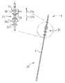
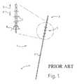
- FIG. 1shows a stimulation electrode according to the prior art
- FIG. 2shows a stimulation electrode according to the invention
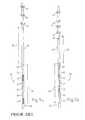
- FIG. 3shows an insertion aid according to the prior art
- FIG. 4shows an insertion aid according to the invention
- FIG. 5 ashows an electrode according to the prior art
- FIG. 5 bshows an electrode according to the invention.
- the stimulation electrode ( 20 )is embodied for a stimulation device for stimulating organs in the case of spinal paraplegia, more particularly in the case of detrusor sphincter dyssynergia and dysfunctions of organs in the lesser pelvis, comprising an electrode shaft ( 2 ), at one end of which an electrode tip ( 3 ) is arranged for emitting a stimulation signal and at the other end of which a connection region ( 4 ) is provided for a signal line.
- the fixationshould be arranged on the electrode in the vicinity of the electrode points in order that—even in the case of patients with paraplegia who break down muscular tissue and subcutaneous fatty tissue at this localization—better fixation and orientation is possible with respect to the nerve root to be stimulated (approximately 1 ⁇ 3 less than the conventional distance between proximal electrode and distal hook).
- a stimulation electrode ( 20 )characterized in that the holding means ( 22 ) preventing the withdrawal and holding means ( 23 ) preventing the advance are spaced apart by a clamping region ( 24 ) and connected thereto, the clamping region ( 24 ) establishing a force-fit connection between electrode shaft ( 2 ) and the holding means ( 22 , 23 ).
- the electrodecan be withdrawn despite the holding means present if a sufficient pulling force is applied.
- the holding meansfold over and only still constitute a very much reduced resistance against movement.
- the latteris characterized in that the holding means ( 22 , 23 ) are formed by barbed hooks directed away from the electrode shaft ( 2 ) at a hook angle ( 26 , 26 a ).
- One embodiment of the stimulation electrodeprovides for the holding means ( 22 ) preventing a withdrawal to be designed symmetrically to a mirror plane intersecting the electrode shaft ( 2 ) perpendicularly, with respect to the holding means ( 23 ) preventing an advance.
- a further embodiment of the stimulation electrodeincludes the fact that the holding means ( 22 , 23 ) are formed by expanding elements that taper toward the electrode shaft at an opening angle ( 26 , 26 a ), the tip of the angle being directed counter to the respective movement direction ( 22 a , 23 a ) in which the holding means ( 22 , 23 ) prevents the advance.
- the inventioncomprises an “insertion aid” ( 40 ), i.e. an insertion aid for a stimulation electrode ( 20 ) according to the invention, which insertion aid comprises an electrode entrance ( 41 ) for introducing the electrode shaft ( 2 ) into the insertion aid ( 40 ), a guide ( 42 ) for inactivating the holding means ( 22 , 23 ) during the positioning procedure of the electrode ( 20 ) and a cannula ( 43 ) for penetrating tissue and is characterized in that the guide ( 42 ) has a conical design.
- the holding meansare placed against the electrode shaft and introduced into the cannula.
- the holding meanscan re-assume e.g. their hook angle ( 26 , 26 a ) only after leaving the cannula and thus provide the desired hold in the tissue.
- the insertion aid according to the inventionis characterized in that the conical guide is arranged such that a widened opening region ( 44 ) is on the side of the electrode entrance ( 41 ) and a smaller opening region ( 45 ) compared thereto is on the side of the cannula ( 43 ).
- a handling aid ( 46 ) on the insertion aidis made.
- An insertion aid ( 30 ) according to the prior artonly has a cylindrical, rectilinear guide region ( 31 ) which cannot, in particular, exert any influence on holding means preventing an advance. These could not be applied using the insertion aid ( 30 ) according to the prior art.
- the inventionrelates to a method for stimulating organs in the case of spinal paraplegia, more particularly in the case of detrusor sphincter dyssynergia, by means of preferably 2 or 4 stimulation electrodes according to the invention, the method comprising the following steps.
- a soft start of the stimulationis carried out over a first short period of time—the “start time”—in a first method step.
- Alternate switching on for an “on time” and subsequent switching off for an “off time” of the stimulationtake place in a second method step, the intensity of the stimulation signal during the second method step and also the ratio of “on time” to “off time” being available as selectable program parameters.
- the method according to the inventionprovides the “start time” in the range of 1 s-30 s for selection as a parameter, preferably as 8 s.
- a further preferred parameter of the methodcomprises that the “on time” in a first program lies in the range of 10 min-60 min, and preferably is 29 min.
- a further moreover preferred parameter of the methodcomprises that the “off time” lies in the range of 5 min-40 min, and preferably is 15 min.
- the “on time” in a second programlies in the range of 1 min-30 min and a stimulation signal is continuously between 0.5 V and 3 V, preferably 0.7 V, in the process.
- this embodimentserves to initiate an erection.
- programming in respect of initiating micturitioncan be carried out under co-stimulation with the detrusor stimulation if the sacral neuromodulation is implanted at an early stage.
- FIGS. 5 a and 5 bA further expedient embodiment of the stimulation electrode according to the invention is illustrated in FIGS. 5 a and 5 b .
- FIG. 5 ashows an electrode according to the prior art.
- the electrode tip 51comprises a front tip end 52 , which simplifies the penetration into the tissue.
- contact regions 53are arranged on the electrode shaft and separated from one another by insulation regions 54 .
- an arrangement of barbed hooks 56which are used as withdrawal-preventing holding means, follow at a distance 57 of approximately 8 mm.
- FIG. 5 bshows a stimulation electrode according to the invention with a front tip end 58 at the electrode tip 59 , following which electrode rings 61 are arranged on the electrode shaft 60 at a distance of approximately 3 mm.
- the electrode rings 61themselves are spaced apart from one another by intermediate regions 62 , the distance in each case likewise being approximately 3 mm. Stimulation of the nerve(s) occurs in this stimulation region 63 of the arrangement of the electrode rings 61 .
- the stimulation region 63is offset from the region of the fixing means with the holding means 64 preventing a withdrawal (barbed hooks in the pulling direction) and holding means 65 preventing an advance (barbed hooks in the pushing direction) by a distance of approximately 4-6 mm, preferably 5 mm, along the electrode shaft 60 .
- the closer positioning of the fixing meansachieves improved positional stability of the implanted stimulation electrode and hence an improved working result.
- one or more markings 66are also provided on the electrode shaft; these mark the penetration depth, particularly during the application procedure of the electrode.
- the method according to the inventionis distinguished by virtue of the fact that, during a first program, stimulation of a is effected a range of between 0.5 V and 3 V, preferably at 0.7 V.
- the second programcan act as preparation for some purpose and can achieve a desired effect if switched on at the same time as program 1 of a second stimulator.
- an improved resultcan be achieved, optionally, for initiating micturition by pre-stimulation with the second program and adding the basic program (programming 1 ).
- the second programcan also operate in a range of between 0.5 V and 3 V, preferably at 0.7 V.
Landscapes
- Health & Medical Sciences (AREA)
- Radiology & Medical Imaging (AREA)
- Engineering & Computer Science (AREA)
- Biomedical Technology (AREA)
- Nuclear Medicine, Radiotherapy & Molecular Imaging (AREA)
- Life Sciences & Earth Sciences (AREA)
- Animal Behavior & Ethology (AREA)
- General Health & Medical Sciences (AREA)
- Public Health (AREA)
- Veterinary Medicine (AREA)
- Heart & Thoracic Surgery (AREA)
- Cardiology (AREA)
- Gastroenterology & Hepatology (AREA)
- Electrotherapy Devices (AREA)
Abstract
Description
- 1 Electrode (prior art)
- 2 Electrode shaft
- 3 Electrode tip
- 4 Connection region
- 5 Fixing means
- 6 Withdrawal direction
- 7 Holding means preventing a withdrawal
- 8 Hook angle
- 9 Advance direction
- 20 Electrode
- 21 Fixing means
- 22 Holding means preventing a withdrawal
- 22aWithdrawal direction
- 23 Holding means preventing an advance
- 23aAdvance direction
- 24 Clamping region
- 25 Kink region
- 26 Hook angle (advance)
- 26aHook angle (withdrawal)
- 30 Insertion aid (prior art)
- 31 Guide
- 40 Insertion aid
- 41 Electrode entrance
- 42 Guide
- 43 Cannula
- 44 Widened opening region
- 45 Reduced opening region
- 46 Handling aid
- 51 Electrode tip
- 52 Front tip end
- 53 Contact region
- 54 Insulation region
- 55 Stimulation region
- 56 Barbed hook
- 57 Distance
- 58 Tip end
- 59 Electrode tip
- 60 Electrode shaft
- 61 Electrode rings
- 62 Intermediate region
- 63 Stimulation region
- 64 Barbed hook in the pulling direction
- 65 Barbed hook in the pushing direction
- 66 Marking
Claims (18)
Applications Claiming Priority (4)
| Application Number | Priority Date | Filing Date | Title |
|---|---|---|---|
| DE102009040963.7 | 2009-09-11 | ||
| DE102009040963 | 2009-09-11 | ||
| DE102009040963ADE102009040963A1 (en) | 2009-09-11 | 2009-09-11 | Sacral neuromodulator |
| PCT/DE2010/001000WO2011029419A2 (en) | 2009-09-11 | 2010-08-30 | Sacral neuromodulator |
Related Parent Applications (1)
| Application Number | Title | Priority Date | Filing Date |
|---|---|---|---|
| PCT/DE2010/001000ContinuationWO2011029419A2 (en) | 2009-09-11 | 2010-08-30 | Sacral neuromodulator |
Publications (2)
| Publication Number | Publication Date |
|---|---|
| US20120221015A1 US20120221015A1 (en) | 2012-08-30 |
| US9248284B2true US9248284B2 (en) | 2016-02-02 |
Family
ID=43448767
Family Applications (1)
| Application Number | Title | Priority Date | Filing Date |
|---|---|---|---|
| US13/415,166ActiveUS9248284B2 (en) | 2009-09-11 | 2012-03-08 | Sacral neuromodulator |
Country Status (4)
| Country | Link |
|---|---|
| US (1) | US9248284B2 (en) |
| EP (1) | EP2475419B1 (en) |
| DE (1) | DE102009040963A1 (en) |
| WO (1) | WO2011029419A2 (en) |
Families Citing this family (1)
| Publication number | Priority date | Publication date | Assignee | Title |
|---|---|---|---|---|
| CN107693936A (en)* | 2017-10-23 | 2018-02-16 | 上海光韵达数字医疗科技有限公司 | Sacral nerve stimulation electrode fixing device |
Citations (16)
| Publication number | Priority date | Publication date | Assignee | Title |
|---|---|---|---|---|
| GB2048682A (en) | 1979-04-26 | 1980-12-17 | Top Kk | Apparatus for introducing a wire into an animal body |
| US6041258A (en) | 1997-05-28 | 2000-03-21 | Transneuronix, Inc. | Medical stimulation |
| US20030045919A1 (en)* | 2001-08-31 | 2003-03-06 | Swoyer John Matthew | Implantable medical electrical stimulation lead fixation method and apparatus |
| US20030233126A1 (en) | 2002-06-12 | 2003-12-18 | Alfred E. Mann Institute For Biomedical Engineering | Injection devices and methods for testing implants |
| US20040210245A1 (en) | 2002-07-26 | 2004-10-21 | John Erickson | Bendable needle with removable stylet |
| US20040230279A1 (en)* | 2003-04-11 | 2004-11-18 | Cates Adam W. | Subcutaneous lead with tined fixation |
| US20050010260A1 (en)* | 2002-09-06 | 2005-01-13 | Medtronic, Inc. | Method, system and device for treating disorders of the pelvic floor by electrical stimulation of and drug delivery to the pudendal and sacral nerves |
| US20050143783A1 (en)* | 2003-05-11 | 2005-06-30 | Boveja Birinder R. | Method and system for providing pulsed electrical stimulation to sacral plexus of a patient to provide therapy for urinary incontinence and urological disorders |
| US20060004421A1 (en) | 2004-02-12 | 2006-01-05 | Bennett Maria E | Systems and methods for bilateral stimulation of left and right branches of the dorsal genital nerves to treat dysfunctions, such as urinary incontinence |
| US20060190047A1 (en) | 2005-02-23 | 2006-08-24 | Medtronic, Inc. | Implantable medical device providing adaptive neurostimulation therapy for incontinence |
| US20070100411A1 (en) | 2005-10-27 | 2007-05-03 | Medtronic, Inc. | Implantable medical electrical stimulation lead fixation method and apparatus |
| US20070173900A1 (en)* | 2006-01-24 | 2007-07-26 | Medtronic, Inc. | Transobturator lead implantation for pelvic floor stimulation |
| US20080103534A1 (en)* | 2006-10-31 | 2008-05-01 | Medtronic, Inc. | Implantable medical elongated member including fixation elements along an interior surface |
| US20080132970A1 (en) | 2006-12-05 | 2008-06-05 | Giancarlo Barolat | Method and system for treatment of intractable scrotal and/or testicular pain |
| US20090012592A1 (en) | 2006-07-10 | 2009-01-08 | Ams Research Corporation | Tissue anchor |
| US20100131036A1 (en)* | 2008-05-23 | 2010-05-27 | Wolfgang Geistert | Implantable electrode line |
- 2009
- 2009-09-11DEDE102009040963Apatent/DE102009040963A1/ennot_activeWithdrawn
- 2010
- 2010-08-30EPEP10779204.6Apatent/EP2475419B1/enactiveActive
- 2010-08-30WOPCT/DE2010/001000patent/WO2011029419A2/enactiveApplication Filing
- 2012
- 2012-03-08USUS13/415,166patent/US9248284B2/enactiveActive
Patent Citations (19)
| Publication number | Priority date | Publication date | Assignee | Title |
|---|---|---|---|---|
| GB2048682A (en) | 1979-04-26 | 1980-12-17 | Top Kk | Apparatus for introducing a wire into an animal body |
| US6041258A (en) | 1997-05-28 | 2000-03-21 | Transneuronix, Inc. | Medical stimulation |
| US6165180A (en) | 1997-05-28 | 2000-12-26 | Transneuronix, Inc. | Medical device handle for use in laparoscopic surgery |
| DE69825588T2 (en) | 1997-05-28 | 2005-01-05 | Transneuronix Inc. | IMPLANTABLE DEVICE FOR ELECTROSTIMULATION AND / OR MONITORING OF TUMBLER WOVEN FABRICS |
| US20030045919A1 (en)* | 2001-08-31 | 2003-03-06 | Swoyer John Matthew | Implantable medical electrical stimulation lead fixation method and apparatus |
| US6999819B2 (en) | 2001-08-31 | 2006-02-14 | Medtronic, Inc. | Implantable medical electrical stimulation lead fixation method and apparatus |
| US20030233126A1 (en) | 2002-06-12 | 2003-12-18 | Alfred E. Mann Institute For Biomedical Engineering | Injection devices and methods for testing implants |
| US20040210245A1 (en) | 2002-07-26 | 2004-10-21 | John Erickson | Bendable needle with removable stylet |
| US20050010260A1 (en)* | 2002-09-06 | 2005-01-13 | Medtronic, Inc. | Method, system and device for treating disorders of the pelvic floor by electrical stimulation of and drug delivery to the pudendal and sacral nerves |
| US20040230279A1 (en)* | 2003-04-11 | 2004-11-18 | Cates Adam W. | Subcutaneous lead with tined fixation |
| US20050143783A1 (en)* | 2003-05-11 | 2005-06-30 | Boveja Birinder R. | Method and system for providing pulsed electrical stimulation to sacral plexus of a patient to provide therapy for urinary incontinence and urological disorders |
| US20060004421A1 (en) | 2004-02-12 | 2006-01-05 | Bennett Maria E | Systems and methods for bilateral stimulation of left and right branches of the dorsal genital nerves to treat dysfunctions, such as urinary incontinence |
| US20060190047A1 (en) | 2005-02-23 | 2006-08-24 | Medtronic, Inc. | Implantable medical device providing adaptive neurostimulation therapy for incontinence |
| US20070100411A1 (en) | 2005-10-27 | 2007-05-03 | Medtronic, Inc. | Implantable medical electrical stimulation lead fixation method and apparatus |
| US20070173900A1 (en)* | 2006-01-24 | 2007-07-26 | Medtronic, Inc. | Transobturator lead implantation for pelvic floor stimulation |
| US20090012592A1 (en) | 2006-07-10 | 2009-01-08 | Ams Research Corporation | Tissue anchor |
| US20080103534A1 (en)* | 2006-10-31 | 2008-05-01 | Medtronic, Inc. | Implantable medical elongated member including fixation elements along an interior surface |
| US20080132970A1 (en) | 2006-12-05 | 2008-06-05 | Giancarlo Barolat | Method and system for treatment of intractable scrotal and/or testicular pain |
| US20100131036A1 (en)* | 2008-05-23 | 2010-05-27 | Wolfgang Geistert | Implantable electrode line |
Non-Patent Citations (1)
| Title |
|---|
| European Search Report, European Patent Application No. 10 779 204.6, dated Mar. 12, 2013 (6 pages). |
Also Published As
| Publication number | Publication date |
|---|---|
| WO2011029419A2 (en) | 2011-03-17 |
| US20120221015A1 (en) | 2012-08-30 |
| DE102009040963A1 (en) | 2011-03-17 |
| WO2011029419A3 (en) | 2011-06-03 |
| EP2475419B1 (en) | 2017-04-12 |
| EP2475419A2 (en) | 2012-07-18 |
Similar Documents
| Publication | Publication Date | Title |
|---|---|---|
| US11213675B2 (en) | Implantable lead affixation structure for nerve stimulation to alleviate bladder dysfunction and other indication | |
| US11103280B2 (en) | Lead insertion devices and associated systems and methods | |
| EP2252365B1 (en) | Temporary neurostimulation lead identification device | |
| EP3393574B1 (en) | Systems to provide sympathetic modulation therapy | |
| US11110282B2 (en) | Implantable electrical stimulator with deflecting tip lead | |
| US8145323B2 (en) | Implantable medical electrical stimulation lead fixation method and apparatus | |
| US8200343B2 (en) | Implantable medical electrical stimulation lead fixation method and apparatus | |
| US20100318098A1 (en) | Systems and Methods for Implanting Medical Devices | |
| US20070255367A1 (en) | Implantable Medical Electrical Stimulation Lead Fixation Method and Apparatus | |
| US20110071606A1 (en) | Bifurcated lead system and apparatus | |
| US9993639B2 (en) | Implantable medical elongated member including a tissue receiving fixation cavity | |
| US9248284B2 (en) | Sacral neuromodulator | |
| US10314614B2 (en) | Arcuate introducer |
Legal Events
| Date | Code | Title | Description |
|---|---|---|---|
| AS | Assignment | Owner name:EBERHARD-KARLS-UNIVERSITAT UNIVERSITATSKLINIKUM TU Free format text:ASSIGNMENT OF ASSIGNORS INTEREST;ASSIGNOR:SIEVERT, KARL-DIETRICH;REEL/FRAME:028226/0083 Effective date:20120507 | |
| AS | Assignment | Owner name:SIEVERT, KARL-DIETRICH, GERMANY Free format text:ASSIGNMENT OF ASSIGNORS INTEREST;ASSIGNOR:EBERHARD-KARLS-UNIVERSITAT UNIVERSITATSKLINIKUM TUBINGEN;REEL/FRAME:031631/0320 Effective date:20131107 | |
| FEPP | Fee payment procedure | Free format text:PAYOR NUMBER ASSIGNED (ORIGINAL EVENT CODE: ASPN); ENTITY STATUS OF PATENT OWNER: SMALL ENTITY | |
| STCF | Information on status: patent grant | Free format text:PATENTED CASE | |
| MAFP | Maintenance fee payment | Free format text:PAYMENT OF MAINTENANCE FEE, 4TH YR, SMALL ENTITY (ORIGINAL EVENT CODE: M2551); ENTITY STATUS OF PATENT OWNER: SMALL ENTITY Year of fee payment:4 | |
| MAFP | Maintenance fee payment | Free format text:PAYMENT OF MAINTENANCE FEE, 8TH YR, SMALL ENTITY (ORIGINAL EVENT CODE: M2552); ENTITY STATUS OF PATENT OWNER: SMALL ENTITY Year of fee payment:8 |