US9248253B2 - Winged catheter assembly - Google Patents
Winged catheter assemblyDownload PDFInfo
- Publication number
- US9248253B2 US9248253B2US11/842,338US84233807AUS9248253B2US 9248253 B2US9248253 B2US 9248253B2US 84233807 AUS84233807 AUS 84233807AUS 9248253 B2US9248253 B2US 9248253B2
- Authority
- US
- United States
- Prior art keywords
- catheter
- catheter body
- lumen
- port
- vessel
- Prior art date
- Legal status (The legal status is an assumption and is not a legal conclusion. Google has not performed a legal analysis and makes no representation as to the accuracy of the status listed.)
- Active, expires
Links
Images


Classifications
- A—HUMAN NECESSITIES
- A61—MEDICAL OR VETERINARY SCIENCE; HYGIENE
- A61M—DEVICES FOR INTRODUCING MEDIA INTO, OR ONTO, THE BODY; DEVICES FOR TRANSDUCING BODY MEDIA OR FOR TAKING MEDIA FROM THE BODY; DEVICES FOR PRODUCING OR ENDING SLEEP OR STUPOR
- A61M25/00—Catheters; Hollow probes
- A61M25/0021—Catheters; Hollow probes characterised by the form of the tubing
- A61M25/0023—Catheters; Hollow probes characterised by the form of the tubing by the form of the lumen, e.g. cross-section, variable diameter
- A61M25/0026—Multi-lumen catheters with stationary elements
- A61M25/003—Multi-lumen catheters with stationary elements characterized by features relating to least one lumen located at the distal part of the catheter, e.g. filters, plugs or valves
- A—HUMAN NECESSITIES
- A61—MEDICAL OR VETERINARY SCIENCE; HYGIENE
- A61M—DEVICES FOR INTRODUCING MEDIA INTO, OR ONTO, THE BODY; DEVICES FOR TRANSDUCING BODY MEDIA OR FOR TAKING MEDIA FROM THE BODY; DEVICES FOR PRODUCING OR ENDING SLEEP OR STUPOR
- A61M25/00—Catheters; Hollow probes
- A61M25/0067—Catheters; Hollow probes characterised by the distal end, e.g. tips
- A61M25/0068—Static characteristics of the catheter tip, e.g. shape, atraumatic tip, curved tip or tip structure
- A61M25/007—Side holes, e.g. their profiles or arrangements; Provisions to keep side holes unblocked
- A—HUMAN NECESSITIES
- A61—MEDICAL OR VETERINARY SCIENCE; HYGIENE
- A61M—DEVICES FOR INTRODUCING MEDIA INTO, OR ONTO, THE BODY; DEVICES FOR TRANSDUCING BODY MEDIA OR FOR TAKING MEDIA FROM THE BODY; DEVICES FOR PRODUCING OR ENDING SLEEP OR STUPOR
- A61M25/00—Catheters; Hollow probes
- A61M25/0067—Catheters; Hollow probes characterised by the distal end, e.g. tips
- A61M25/0074—Dynamic characteristics of the catheter tip, e.g. openable, closable, expandable or deformable
- A61M25/0075—Valve means
- A—HUMAN NECESSITIES
- A61—MEDICAL OR VETERINARY SCIENCE; HYGIENE
- A61M—DEVICES FOR INTRODUCING MEDIA INTO, OR ONTO, THE BODY; DEVICES FOR TRANSDUCING BODY MEDIA OR FOR TAKING MEDIA FROM THE BODY; DEVICES FOR PRODUCING OR ENDING SLEEP OR STUPOR
- A61M25/00—Catheters; Hollow probes
- A61M25/0021—Catheters; Hollow probes characterised by the form of the tubing
- A61M25/0023—Catheters; Hollow probes characterised by the form of the tubing by the form of the lumen, e.g. cross-section, variable diameter
- A61M25/0026—Multi-lumen catheters with stationary elements
- A61M25/003—Multi-lumen catheters with stationary elements characterized by features relating to least one lumen located at the distal part of the catheter, e.g. filters, plugs or valves
- A61M2025/0031—Multi-lumen catheters with stationary elements characterized by features relating to least one lumen located at the distal part of the catheter, e.g. filters, plugs or valves characterized by lumina for withdrawing or delivering, i.e. used for extracorporeal circuit treatment
- A—HUMAN NECESSITIES
- A61—MEDICAL OR VETERINARY SCIENCE; HYGIENE
- A61M—DEVICES FOR INTRODUCING MEDIA INTO, OR ONTO, THE BODY; DEVICES FOR TRANSDUCING BODY MEDIA OR FOR TAKING MEDIA FROM THE BODY; DEVICES FOR PRODUCING OR ENDING SLEEP OR STUPOR
- A61M25/00—Catheters; Hollow probes
- A61M25/0021—Catheters; Hollow probes characterised by the form of the tubing
- A61M25/0023—Catheters; Hollow probes characterised by the form of the tubing by the form of the lumen, e.g. cross-section, variable diameter
- A61M25/0026—Multi-lumen catheters with stationary elements
- A61M2025/0037—Multi-lumen catheters with stationary elements characterized by lumina being arranged side-by-side
Definitions
- the present applicationrelates generally to a catheter for use in transporting fluids, and more particularly, to a multi-lumen catheter assembly for transporting fluids from the patient's body for extracorporeal treatment, and returning the treated fluids to the body.
- Multi-lumen cathetersare commonly used for transporting bodily fluids during an extracorporeal treatment process for the bodily fluid.
- a fluidis withdrawn from the body through one of the lumens, generally referred to as the aspiration, or withdrawal, lumen.
- the fluidis subjected to a treatment process, and thereafter returned to the body through the other lumen, generally referred to as the infusion, or return, lumen.
- the extracorporeal treatmentinvolves a hemodialysis procedure.
- bloodis withdrawn from a blood vessel through the aspiration lumen and routed to a dialyzer for treatment.
- the cleansed bloodis then returned to the vessel through the infusion lumen.
- a catheteris generally inserted into the body through either the internal jugular vein, subclavian vein or femoral vein.
- extracorporeal catheterscan also be used for other procedures, such as pheresis and hemofiltration, in which a fluid is removed from the body for treatment and later returned to the body.
- a variety of hemodialysis cathetersare commercially available.
- a dual lumen catheterwherein one lumen (e.g., the blood infusion lumen) terminates distal to the other lumen (e.g., the blood aspiration lumen).
- Some catheters of this typeare provided with a midline split (e.g., the Uldall catheter), while others do not have such a split (e.g., the COOK® DDS catheter); 2) catheters having a slitted valve in the distal tip that acts as a pressure valve opening.
- This valveopens inwardly for blood aspiration, outwardly for blood infusion, and remains closed when not in use (e.g., the Groshong catheter); 3) cuffed central venous silicone catheters that are tunneled underneath the skin to reduce infection (e.g., Broviac, Leonard and Hickman catheters); 4) dual lumen catheters having a tapered tip and two adjacent holes communicating with one lumen just proximal to the tip to assist with outflow, and two adjacent holes communicating with the other lumen (180 degrees removed) just proximal to the first set of holes to assist with inflow (e.g., the Mahurkar catheter); 5) dual lumen catheters having a diverting structure consisting of a shoulder that has a straight up distal face and a sloped proximal face to reduce access recirculation and raise pressure in the vicinity of the inlet aperture (U.S. Pat. No. 6,409,700); and 6) catheters designed for femoral approach having two sets of staggered side ports, resulting
- One problem with existing multi-lumen cathetersis that such catheters can experience decreased flow rates over time. Decreased flow rates may be caused by, among other things, blockage of the aspiration and/or infusion ports in the catheter. Various factors can cause a port to become blocked.
- One common cause of port blockageis the inadvertent positioning of one or more ports of the catheter against the vessel wall. This positioning hinders the free flow of fluid through the obstructed port, and in some cases, prevents fluid flow altogether.
- Another common cause of port blockageis the formation of fibrin sheaths along the ports. Fibrin sheaths may be formed, e.g., in response to the vessel wall washing effect or clotting.
- Some catheterssuch as the Mahurkar catheter described above, must be rotated if inflow is blocked because the catheter is up against the vein wall. Although each of these techniques may be at least partially effective in reducing some types of blockage, reduced flow rate continues to be a problem in the art.
- multi-lumen catheter assemblyfor use in the extracorporeal treatment of bodily fluids, wherein the multi-lumen catheter assembly is structured in a manner to minimize port blockage, and to provide for optimal fluid flow through the lumens of the catheter.
- the inventioncomprises a catheter assembly comprising a catheter body having a plurality of lumens extending therein.
- the catheter bodyhas an aspiration port in communication with a first lumen for transporting fluid withdrawn from a body vessel, and an infusion port in communication with a second lumen for return of fluid to the vessel.
- the catheter bodycomprises a flap portion extending radially from the catheter body and defining the aspiration port. The flap portion is configured and arranged to space the aspiration port from a wall of the body vessel.
- the inventioncomprises a catheter assembly for use in the extracorporeal treatment of a body fluid of a patient.
- the catheter assemblycomprises an elongated catheter body having a proximal end, a distal end, a pair of lumens extending at least substantially therethrough, and a septum separating the lumens.
- One of the lumenscomprises an aspiration lumen
- the other lumencomprises an infusion lumen.
- An aspiration portis disposed along a length of the catheter body in communication with the aspiration lumen for receiving body fluid from a body vessel of the patient for transport to a treatment unit, and an infusion port is disposed in communication with the infusion lumen for returning treated body fluid to the vessel.
- the catheter bodyincludes a flap portion extending radially therefrom and defining the aspiration port. The flap portion is structured to substantially maintain the radial extension from the catheter body when inserted into the body vessel and engaging a wall of the vessel.
- the inventioncomprises a method for treating a body fluid.
- An assemblyis provided for transporting the body fluid.
- the assemblycomprises a catheter body having a plurality of lumens extending therein.
- the catheter bodyhas an aspiration port in communication with a first lumen for transporting fluid withdrawn from a body vessel, and an infusion port in communication with a second lumen for returning fluid to the vessel.
- the catheter bodycomprises a flap extending radially from the catheter body and defining the aspiration port. The flap is structured to substantially maintain the radial extension from the catheter body when inserted into the body vessel and engaging a wall of the vessel.
- a distal end of the assemblyis inserted into the vessel, and the body fluid to be treated is aspirated from the vessel through the aspiration port.
- the aspirated fluidis transported through the first lumen to a treatment instrument.
- the fluidis treated in the treatment instrument, and treated fluid is thereafter transported from the treatment instrument through the second lumen.
- the treated fluidis then infused back into
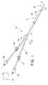
- FIG. 1is a perspective view of a catheter assembly according to one embodiment of the present invention
- FIG. 2is an enlarged side view of the distal portion of the catheter assembly of FIG. 1 ;
- FIG. 3is a longitudinal sectional view of the catheter assembly taken along line 3 - 3 of FIG. 2 ;
- FIG. 4is a transverse sectional view of the catheter assembly, taken along line 4 - 4 of FIG. 2 ;
- FIG. 5is a side view of the distal portion of the catheter assembly rotated 90 degrees in a first direction from the view of FIG. 2 ;
- FIG. 6is an end view of the catheter assembly shown in FIG. 5 ;
- FIG. 7is a side view of the distal portion of the catheter assembly rotated 90 degrees in a second direction from the view of FIG. 2 ;
- FIG. 8is an enlarged side view of the catheter assembly of FIG. 2 , wherein an introducer is provided over the distal end of the catheter body;
- FIG. 9is an exploded view of another embodiment of a catheter assembly.
- the present inventionis directed to a catheter assembly for use in the extracorporeal treatment of bodily fluids.
- the bodily fluidsare transported from the body through an aspiration lumen in the catheter, and are thereafter transported to an instrument for extracorporeal treatment.
- the treated fluidsare then returned to the body through an infusion lumen in the catheter.
- inventive extracorporeal catheteris suitable for multiple uses involving inflow and outflow of bodily fluids.
- the inventionwill be primarily described hereinafter with reference to one of its intended uses, namely as a hemodialysis catheter for use in the extracorporeal treatment of blood.
- the hemodialysis catheterenables blood inflow without disruption, and blood return without hemolysis.
- the cathetercan be used for other extracorporeal fluid treatments in which a body fluid is withdrawn from the body, subjected to a treatment process, and thereafter returned to the body. Pheresis and hemofiltration are non-limiting examples of such procedures.
- proximal and distalwill be used to describe the axial ends of the catheter assembly, as well as the axial ends of various component features.
- proximal endrefers to the end of the catheter assembly (or component) that is closest to the operator during use of the assembly.
- distal endrefers to the end of the assembly (or component) that is initially inserted into the patient, or that is closest to the patient during use.
- FIG. 1is a perspective view of a catheter assembly 10 according to one embodiment of the present invention.
- Catheter assembly 10includes a catheter body 12 .
- Catheter body 12comprises an elongated tubular member formed of a conventional polymer commonly used for such purposes in medical catheters, such as radiopaque polyurethane. Other conventional materials used for such purposes in the medical device art may be substituted. Non-limiting examples of such materials include silicone, polyurethane and PTFE.
- Catheter body 12has a proximal end 14 , a tapered distal end 16 , and includes lumens 18 , 20 extending at least partially therethrough ( FIGS. 3 , 4 ).
- catheter assembly 10includes a bifurcated fitting, such as manifold 30 .
- Manifold 30may be provided with conventional suture wings 31 if desired.
- Extension tubes 32 , 34extend in the proximal direction from manifold 30 .
- Extension tubes 32 , 34comprise generally flexible polymers commonly used for such purposes in the medical device art, such as polyurethane, PVC and silicone.
- Catheter body 12is received in manifold 30 in conventional fashion, such as by insert molding catheter body proximal end 14 in a suitably-sized channel in manifold 30 .
- Extension tube 32communicates with fluid aspiration lumen 18 in catheter body 12 for receiving fluid withdrawn from a body vessel in the patient.
- a luer lock or other suitable connector 36is fitted onto the proximal end of extension tube 32 in conventional fashion.
- connector 36is engaged in mating relationship with a connector associated with an ingress opening of a treatment instrument 40 , such as a dialyzer, for establishing a flow path of blood to the dialyzer.
- Extension tube 34communicates with blood infusion lumen 20 in catheter body 12 .
- a luer lock or other suitable connector 38is fitted onto the proximal end of extension tube 34 .
- Connector 38is engaged in mating relationship with a connector associated with an egress opening of dialyzer 40 for receiving treated blood from the dialyzer.
- Dialyzer 40 and its ingress and egress openingsare shown schematically in FIG. 1 .
- Conventional clamps 37 , 39may be provided for selectively controlling the flow of blood between the dialyzer and the catheter body.
- FIG. 2is an enlarged side view of the distal portion of the catheter assembly 10 of FIG. 1 .
- FIG. 3is a longitudinal sectional view of catheter assembly 10 taken along line 3 - 3 of FIG. 2 .
- FIG. 4is a transverse sectional view of catheter assembly 10 , taken along line 4 - 4 of FIG. 2 .
- FIGS. 3 and 4illustrate the lumens 18 , 20 , that extend longitudinally through at least the major portion of the length of catheter body 12 .
- lumen 18is the fluid aspiration, or withdrawal, lumen
- lumen 20is the fluid infusion, or return, lumen.
- Septum 22is provided internally of catheter body 12 to separate lumens 18 and 20 .
- aspiration lumen 18extends from aspiration port 24 to the proximal end of catheter body 12 .
- FIG. 5is a side view of the distal portion of the catheter assembly rotated 90 degrees in a first direction from the view of FIG. 2 .
- FIG. 6is an end view of the catheter assembly shown in FIG. 5 .
- FIG. 7is a side view of the distal portion of the catheter assembly rotated 90 degrees in a second direction from the view of FIG. 2 .
- a flap 25is molded or otherwise formed in catheter body 12 . Flap 25 extends outwardly from catheter body 12 in the nature of a “wing.” Aspiration port 24 is defined by the distension of flap 25 from main catheter body 12 . In a preferred embodiment, a second wing-like flap 28 is molded or otherwise formed in catheter body 12 proximal to flap 25 to define a second aspiration port 27 . Each aspiration port communicates with aspiration lumen 18 , thereby providing a passageway for fluid to aspirate from the vessel into the lumen. Preferably, beading 29 or other “filler” material is provided in the space between aspiration port 24 and the closed distal end 19 of lumen 18 , as shown in FIG.
- additional aspiration portscan be formed along the length of catheter body 12 to increase fluid flow into the aspiration lumen 18 .
- additional portsare also preferably defined by flaps as described above, however this is not necessarily required, and such additional ports may have other configurations suitable for aspiration of a fluid.
- Fluid infusion lumen 20typically extends from infusion port 21 to the proximal end of catheter body 12 .
- infusion port 21comprises an opening at the distal end of catheter body 12 in communication with infusion lumen 20 .
- one or more side ports 23may be provided along the length of catheter body 12 that also communicate with infusion lumen 20 .
- Side port 23provides extra surface area for infusion of treated blood into the vessel in addition to infusion port 21 .
- aspiration ports 24 and 27are positioned proximal to infusion port 21 and side port 23 along the length of catheter body 12 . This arrangement is preferred, but not crucial to the invention.
- Positioning the aspiration port(s) proximal to the infusion port and side port(s)enhances the efficiency of the extracorporeal procedure, by assuring that the majority of the blood that is aspirated through the aspiration port(s) is not the same blood that has previously been cleansed and returned to the vessel through the infusion port and/or side port.
- Flaps 25 , 28are configured and positioned such that catheter body 12 resists direct apposition with the vessel wall.
- the “wing-like” extension of flaps 25 , 28 from catheter body 12increases the effective radial diameter of the catheter at the site of the wings, thereby distending the vessel wall away from intimate contact with the underlying aspiration port openings 24 , 27 .
- flaps 25 , 28are formed and configured such that they are capable of assuming a low profile upon insertion or removal, and thereafter flaring radially once positioned at the treatment site in the vessel.
- an introducer sheath 50may be provided over the distal end of catheter assembly 10 .
- introducer sheath 50is shown partially extended in the proximal direction. In this position, introducer sheath 50 covers a portion of flap 25 , thereby urging flap 25 into close association with catheter body 12 .
- sheath 50When sheath 50 is fully extended in the proximal direction it covers each of flaps 25 , 28 .
- flaps 25 , 28assume a low radial profile, such that the radial distension of each flap is substantially reduced, or eliminated altogether. Flaps 25 , 28 remain in this low profile condition as long as sheath 50 is in place on the catheter body.
- sheath 50comprises a splittable structure having an elongated body 52 that tapers to a distal end 54 dimensioned for insertion into the body vessel.
- Elongated body 52is dimensioned to receive the distal end of catheter body 12 therein in a snugly-fitting relationship.
- a pair of ears 55 , 56is provided, which ears may include graspable knobs 57 , 58 for use in splitting the elongated body 52 .
- Splittable introducer sheathsare well known in the medical arts, and a skilled artisan is well aware of the manner of use and splitting of such sheaths.
- Splittable introducer sheathsare commercially available, e.g., from Cook Incorporated, of Bloomington, Ind., as PEEL-AWAY® introducers.
- the leading (distal) end 54 of sheath 50is initially inserted into an opening in the vessel.
- the catheter assembly and introducer sheathare introduced over a wire guide that has previously been positioned in the vessel by conventional means, such as the well-known Seldinger technique.
- the wire guideis removed.
- the sheathis thereafter removed by grasping and pulling the knobs in an outward direction and peeling the sides of the sheath in well-known fashion, leaving the leading (distal) end of the catheter assembly in position in the vessel.
- an introducer sheathsuch as splittable sheath 50
- the use of an introducer sheathis not always necessary, and in some occasions the catheter assembly can be successfully introduced without the use of such a sheath or other introducing device.
- a generally radial forceis applied to the flaps upon insertion into the vessel by the adjacent tissue at the insertion site. This force will cause the flaps to collapse upon insertion, in the same manner as the force of an introducer sheath covering the flaps. Upon entering the vessel, the force is removed, and the flaps expand to the wing-like configuration shown and described. The same principle applies during removal of the catheter assembly from the vessel.
- flaps 25 , 28are preferably formed from catheter body 12 .
- a crescent-shaped cutis formed in the catheter body wall to define the flaps.
- the cutssuch as the crescent-shaped cut described above, may be formed in catheter body 12 in any convenient manner, such as by the use of a small hole-saw.
- the length of the cut(in the axial direction) will be roughly two times the diameter of the catheter, although other dimensions may be substituted if desired.
- the flaps in the catheter bodyare cut to the desired size and shape, the flaps are preferably set in a manner to maintain the distended wing-like configuration relative to the remainder of the catheter body.
- One preferred manner of setting the flapsis by a conventional heat-set or steam-set procedure. Other conventional physical and chemical setting procedures may alternatively be used.
- the particular mode of setting the flapis generally not important, as long as the resulting flap has sufficient strength and structural integrity to at least substantially maintain its distended, or wing-like, configuration under conditions expected to be encountered in the body vessel.
- the flapsare oriented and configured to be substantially atraumatic to tissue, and to be substantially snag resistant when positioned in the vessel.
- the catheter bodycan be formed from multiple initially separate components, which components are alignable for assembly into a unitary elongated body.
- FIG. 9illustrates an exploded view of a catheter assembly 70 formed of three catheter body segments 71 , 72 , 73 .
- this preferred embodimentincludes three initially separate components, more, or fewer, such components may be utilized in a particular case.
- Catheter body segment 71is generally similar to catheter body 12 of the previous embodiments, and comprises a major length of the catheter body.
- lumen 74is the aspiration (withdrawal) lumen
- lumen 76is the infusion (return) lumen.
- a septum 75separates lumens 74 , 76 .
- Catheter body segment 71terminates at a blunt distal end 77 .
- Lumens 74 , 76extend at least substantially through the unitary body.
- catheter body segment 72is molded, such as via a conventional injection molding process, to the general shape illustrated in the figure.
- Segment 72includes one or more flaps, such as flaps 80 , 82 .
- Flaps 80 , 82define aspiration ports 81 , 83 , which ports are in communication with aspiration lumen 74 .
- Aspiration lumen 74terminates in the distal direction within body segment 72 , and a filler material, similar to filler material 29 described above and illustrated schematically in FIG. 3 , may extend within the dead space of the lumen to the distal end of the body segment.
- the distal end 79 of body segment 72includes a smooth tapered contour as shown.
- Catheter body segment 73is configured such that proximal end 85 matches the contour of distal end 79 of body segment 72 .
- Distal end 86tapers to open tip portion 87 to facilitate insertion into the vessel.
- Open tip portion 87communicates with infusion lumen 76 , and defines an infusion port for return of treated fluid to the vessel.
- One or more side portsmay be provided if desired.
- Devices for forming tip configurationsare well known in the medical arts, and those skilled in the art can readily adapt such a device to form body segment 73 .
- a catheterWhen a catheter is formed from one or more body segments as shown in the embodiment of FIG. 9 , all, or some, of the segments may be molded. Molding may be particularly appropriate for the segment ( 72 ) that includes the flap(s) and the aspiration port(s), as it provides a very convenient way of forming the requisite structure (flaps and ports).
- the molded segmentmay then be attached by conventional means, such as adhesion, bonding, etc., to adjoining body segments, such as segments 71 and 73 , which segments 71 , 73 may, or may not, be molded.
- the respective segmentsIn order to provide a secure attachment between the segments, it is preferred that the respective segments be formed from the same, or a similar, composition.
- the methods of forming the catheter body and flaps described hereinare intended to be exemplary, and not exclusive. When armed with the teachings of the present invention, those skilled in the art are readily capable of forming a suitable catheter as described herein, wherein the catheter body includes a flap that defines an underlying port, and which flap has sufficient strength and structural integrity to at least substantially maintain its distended configuration under conditions typically encountered in a body vessel.
- one or more radiopaque markerscan be added along the length of the catheter body, or a radiopaque material may be added to the matrix of all or a part of the catheter body to improve visualization of the catheter in accordance with well-known techniques.
- the catheter bodymay include a hydrophilic coating along all or a part of the length of the catheter to facilitate entry into the vessel.
- the catheter bodycan be coated with various medicaments along all or a part of the length of the catheter body. Non-limiting examples of such medicaments include antiproliferatives, anticoagulants, thrombolytics, fibrinolytics, and antimicrobials.
Landscapes
- Health & Medical Sciences (AREA)
- Life Sciences & Earth Sciences (AREA)
- Biophysics (AREA)
- Pulmonology (AREA)
- Engineering & Computer Science (AREA)
- Anesthesiology (AREA)
- Biomedical Technology (AREA)
- Heart & Thoracic Surgery (AREA)
- Hematology (AREA)
- Animal Behavior & Ethology (AREA)
- General Health & Medical Sciences (AREA)
- Public Health (AREA)
- Veterinary Medicine (AREA)
- External Artificial Organs (AREA)
Abstract
Description
Claims (15)
Priority Applications (1)
| Application Number | Priority Date | Filing Date | Title |
|---|---|---|---|
| US11/842,338US9248253B2 (en) | 2007-08-21 | 2007-08-21 | Winged catheter assembly |
Applications Claiming Priority (1)
| Application Number | Priority Date | Filing Date | Title |
|---|---|---|---|
| US11/842,338US9248253B2 (en) | 2007-08-21 | 2007-08-21 | Winged catheter assembly |
Publications (2)
| Publication Number | Publication Date |
|---|---|
| US20090054825A1 US20090054825A1 (en) | 2009-02-26 |
| US9248253B2true US9248253B2 (en) | 2016-02-02 |
Family
ID=40382869
Family Applications (1)
| Application Number | Title | Priority Date | Filing Date |
|---|---|---|---|
| US11/842,338Active2034-01-03US9248253B2 (en) | 2007-08-21 | 2007-08-21 | Winged catheter assembly |
Country Status (1)
| Country | Link |
|---|---|
| US (1) | US9248253B2 (en) |
Cited By (4)
| Publication number | Priority date | Publication date | Assignee | Title |
|---|---|---|---|---|
| CN107982620A (en)* | 2016-10-26 | 2018-05-04 | 康尔福盛2200有限公司 | multi-lumen indwelling catheter |
| US10004842B2 (en) | 2011-08-11 | 2018-06-26 | Medical Components, Inc. | Method and apparatus for the dialysis of blood |
| USD905853S1 (en) | 2018-02-27 | 2020-12-22 | Medical Components, Inc. | Catheter tip |
| USD984880S1 (en) | 2020-11-06 | 2023-05-02 | Medical Components, Inc. | Clamp with indicator |
Families Citing this family (29)
| Publication number | Priority date | Publication date | Assignee | Title |
|---|---|---|---|---|
| EP3689274A1 (en) | 2007-02-05 | 2020-08-05 | Boston Scientific Limited | Thrombectomy system |
| JP2009273609A (en) | 2008-05-14 | 2009-11-26 | Nippon Sherwood Medical Industries Ltd | Catheter with valve |
| US9005154B2 (en) | 2008-09-26 | 2015-04-14 | Covidien Lp | Valved hemodialysis catheter |
| US9510854B2 (en) | 2008-10-13 | 2016-12-06 | Boston Scientific Scimed, Inc. | Thrombectomy catheter with control box having pressure/vacuum valve for synchronous aspiration and fluid irrigation |
| JP2011050420A (en)* | 2009-08-31 | 2011-03-17 | Nippon Sherwood Medical Industries Ltd | Valved catheter |
| US8496607B2 (en)* | 2009-12-04 | 2013-07-30 | Cook Medical Technologies Llc | Multi-lumen catheter |
| US8591459B2 (en)* | 2009-12-21 | 2013-11-26 | Ethicon Endo-Surgery, Inc. | Use of biomarkers and therapeutic agents with surgical devices |
| EP2624904A1 (en) | 2010-10-05 | 2013-08-14 | Cook Medical Technologies LLC | Infusion catheter and methods |
| US8747343B2 (en)* | 2011-09-30 | 2014-06-10 | Covidien Lp | Hemodialysis catheter with improved side opening design |
| US9072867B2 (en) | 2011-09-30 | 2015-07-07 | Covidien Lp | Catheter with external flow channel |
| US10143822B2 (en) | 2012-07-05 | 2018-12-04 | Covidien Lp | Valved tip catheters |
| WO2014093594A1 (en)* | 2012-12-12 | 2014-06-19 | Buffalo Filter Llc | Filtration device and system |
| US9248221B2 (en) | 2014-04-08 | 2016-02-02 | Incuvate, Llc | Aspiration monitoring system and method |
| US9433427B2 (en) | 2014-04-08 | 2016-09-06 | Incuvate, Llc | Systems and methods for management of thrombosis |
| US9883877B2 (en) | 2014-05-19 | 2018-02-06 | Walk Vascular, Llc | Systems and methods for removal of blood and thrombotic material |
| CN111184554B (en)* | 2014-09-15 | 2024-03-22 | 业聚医疗私人有限公司 | Catheter device |
| WO2016133747A1 (en)* | 2015-02-20 | 2016-08-25 | Portela Soni Medical Llc | Improved urinary catheter, kit and method |
| CN104887248A (en)* | 2015-06-25 | 2015-09-09 | 烟台康博医疗科技有限公司 | Disposable convenient blood sampling device |
| US10702292B2 (en) | 2015-08-28 | 2020-07-07 | Incuvate, Llc | Aspiration monitoring system and method |
| US10561440B2 (en) | 2015-09-03 | 2020-02-18 | Vesatek, Llc | Systems and methods for manipulating medical devices |
| US20170100142A1 (en) | 2015-10-09 | 2017-04-13 | Incuvate, Llc | Systems and methods for management of thrombosis |
| US10226263B2 (en) | 2015-12-23 | 2019-03-12 | Incuvate, Llc | Aspiration monitoring system and method |
| US10492805B2 (en) | 2016-04-06 | 2019-12-03 | Walk Vascular, Llc | Systems and methods for thrombolysis and delivery of an agent |
| WO2018157206A1 (en) | 2017-02-28 | 2018-09-07 | Alexander Koefman | Medical insert |
| US20190060040A1 (en)* | 2017-08-23 | 2019-02-28 | William L. Barham | High Volume Dental Suction Tip with Lower Volume Suction Port |
| US11678905B2 (en) | 2018-07-19 | 2023-06-20 | Walk Vascular, Llc | Systems and methods for removal of blood and thrombotic material |
| CA3152630A1 (en)* | 2019-08-27 | 2021-03-04 | Hollister Incorporated | Sleeved hydrophilic medical products |
| JP2024506374A (en) | 2021-02-15 | 2024-02-13 | ウォーク バスキュラー, エルエルシー | System and method for removing blood and thrombotic material |
| US12274458B2 (en) | 2021-02-15 | 2025-04-15 | Walk Vascular, Llc | Systems and methods for removal of blood and thrombotic material |
Citations (82)
| Publication number | Priority date | Publication date | Assignee | Title |
|---|---|---|---|---|
| US3938530A (en) | 1974-11-15 | 1976-02-17 | Santomieri Louis | Catheter |
| US3946741A (en) | 1974-12-09 | 1976-03-30 | Adair Edwin Lloyd | Urethral catheter and body drainage device |
| US4129129A (en) | 1977-03-18 | 1978-12-12 | Sarns, Inc. | Venous return catheter and a method of using the same |
| US4134402A (en) | 1976-02-11 | 1979-01-16 | Mahurkar Sakharam D | Double lumen hemodialysis catheter |
| US4154242A (en) | 1977-06-17 | 1979-05-15 | Zafmedico Corp. | Bladder catheter |
| US4431426A (en)* | 1979-08-20 | 1984-02-14 | Groshong Leroy E | Methods and apparatus for intravenous therapy and hyperalimentation |
| US4493696A (en) | 1979-12-28 | 1985-01-15 | Allentyne Limited | Hemodialysis cannular for subclavian insertion |
| USRE31855E (en) | 1978-12-01 | 1985-03-26 | Cook, Inc. | Tear apart cannula |
| US4581025A (en) | 1983-11-14 | 1986-04-08 | Cook Incorporated | Sheath |
| US4583968A (en)* | 1983-10-03 | 1986-04-22 | Mahurkar Sakharam D | Smooth bore double lumen catheter |
| US4643711A (en) | 1984-05-25 | 1987-02-17 | Cook, Inc. | Two lumen hemodialysis catheter |
| US4655745A (en) | 1985-07-29 | 1987-04-07 | Corbett Joseph E | Ventricular catheter |
| US4680029A (en) | 1984-02-23 | 1987-07-14 | Sherwood Medical Company | Vena caval catheter |
| US4692141A (en) | 1982-03-08 | 1987-09-08 | Mahurkar Sakharam D | Double lumen catheter |
| US4733669A (en) | 1985-05-24 | 1988-03-29 | Cardiometrics, Inc. | Blood flow measurement catheter |
| US4772268A (en) | 1984-05-25 | 1988-09-20 | Cook Incorporated | Two lumen hemodialysis catheter |
| EP0301854A2 (en) | 1987-07-29 | 1989-02-01 | LAUB, Glenn W. | Percutaneous venous cannula for cardiopulmonary bypass |
| US4878893A (en) | 1988-04-28 | 1989-11-07 | Thomas J. Fogarty | Angioscope with flush solution deflector shield |
| US4904238A (en) | 1987-12-21 | 1990-02-27 | Alcon Laboratories, Inc. | Irrigation/aspiration handpiece |
| US4936826A (en)* | 1988-10-24 | 1990-06-26 | Amarasinghe Disamodha C | Vena cava window |
| US4973301A (en) | 1989-07-11 | 1990-11-27 | Israel Nissenkorn | Catheter and method of using same |
| US4995868A (en) | 1988-10-12 | 1991-02-26 | Bard Limited | Catheter |
| US4995865A (en)* | 1989-06-09 | 1991-02-26 | Worldwide Medical Plastics Inc. | Multi-lumen catheters |
| US5030201A (en)* | 1989-11-24 | 1991-07-09 | Aubrey Palestrant | Expandable atherectomy catheter device |
| US5106368A (en) | 1990-04-20 | 1992-04-21 | Cook Incorporated | Collapsible lumen catheter for extracorporeal treatment |
| US5156597A (en) | 1989-12-30 | 1992-10-20 | B. Braun Melsungen Ag | Transcutaneous implantation catheter |
| US5193533A (en) | 1990-07-09 | 1993-03-16 | Brigham And Women's Hospital | High-pressure jet ventilation catheter |
| US5221256A (en) | 1992-02-10 | 1993-06-22 | Mahurkar Sakharam D | Multiple-lumen catheter |
| US5250034A (en)* | 1990-09-17 | 1993-10-05 | E-Z-Em, Inc. | Pressure responsive valve catheter |
| US5275610A (en) | 1991-05-13 | 1994-01-04 | Cook Incorporated | Surgical retractors and method of use |
| US5352198A (en) | 1993-11-24 | 1994-10-04 | Uresil Corporation | Locking catheter system |
| US5360397A (en)* | 1993-07-02 | 1994-11-01 | Corvita Corporation | Hemodiaylsis catheter and catheter assembly |
| US5409460A (en) | 1993-04-15 | 1995-04-25 | The Beta Group Inc. | Intra-luminal expander assembly |
| US5443449A (en) | 1991-03-01 | 1995-08-22 | Applied Medical Resources Corporation | Cholangiography catheter |
| US5486159A (en) | 1993-10-01 | 1996-01-23 | Mahurkar; Sakharam D. | Multiple-lumen catheter |
| US5509900A (en) | 1992-03-02 | 1996-04-23 | Kirkman; Thomas R. | Apparatus and method for retaining a catheter in a blood vessel in a fixed position |
| US5509897A (en) | 1990-01-08 | 1996-04-23 | The Curators Of The University Of Missouri | Multiple lumen catheter for hemodialysis |
| US5514112A (en) | 1992-10-02 | 1996-05-07 | Boston Scientific Corporation | Drainage catheter and method of use |
| US5518498A (en) | 1992-10-09 | 1996-05-21 | Angiomed Ag | Stent set |
| US5522400A (en) | 1994-11-23 | 1996-06-04 | Uresil Corp | Locking catheter system |
| US5571093A (en) | 1994-09-21 | 1996-11-05 | Cruz; Cosme | Multiple-lumen catheter |
| US5681280A (en) | 1995-05-02 | 1997-10-28 | Heart Rhythm Technologies, Inc. | Catheter control system |
| US5702365A (en)* | 1992-09-08 | 1997-12-30 | King; Toby St. John | Daul-lumen catheter |
| US5713853A (en) | 1995-06-07 | 1998-02-03 | Interventional Innovations Corporation | Methods for treating thrombosis |
| US5749826A (en) | 1996-11-06 | 1998-05-12 | Faulkner; James W. | Urinary incontinence control device |
| US5817067A (en) | 1995-12-01 | 1998-10-06 | Tsukada Medical Research Co., Ltd. | Cap for medical appliance to be retained in human body |
| US5857464A (en) | 1995-06-07 | 1999-01-12 | Desai; Jawahar M. | Catheter for media injection |
| US5885258A (en) | 1996-02-23 | 1999-03-23 | Memory Medical Systems, Inc. | Medical instrument with slotted memory metal tube |
| US5888196A (en) | 1990-03-02 | 1999-03-30 | General Surgical Innovations, Inc. | Mechanically expandable arthroscopic retractors |
| US5957900A (en) | 1996-07-10 | 1999-09-28 | Asahi Kogaku Kogyo Kabushiki Kaisha | Treatment accessory for endoscope |
| US6001079A (en) | 1995-09-05 | 1999-12-14 | Pourchez; Thierry | Multilumen catheter, particularly for hemodialysis |
| US6033397A (en) | 1996-03-05 | 2000-03-07 | Vnus Medical Technologies, Inc. | Method and apparatus for treating esophageal varices |
| US6052612A (en)* | 1995-06-07 | 2000-04-18 | Desai; Jawahar M. | Catheter for media injection |
| US6177049B1 (en) | 1998-06-10 | 2001-01-23 | Dsu Medical Corporation | Reversing flow blood processing system |
| WO2001019425A1 (en) | 1999-09-17 | 2001-03-22 | Cook Incorporated | Medical device including expandable balloon |
| US6238412B1 (en) | 1997-11-12 | 2001-05-29 | William Dubrul | Biological passageway occlusion removal |
| US6270490B1 (en) | 1998-09-08 | 2001-08-07 | Embol-X, Inc. | Venous drainage catheter and method of use |
| US20010018576A1 (en) | 1999-11-24 | 2001-08-30 | Radius International Limited Partnership. | Blood vessel catheter |
| US6283940B1 (en) | 1997-08-29 | 2001-09-04 | S. Grant Mulholland | Catheter |
| US6293958B1 (en)* | 1998-07-27 | 2001-09-25 | Acist Medical Systems, Inc. | Catheter having flow diffusing tip |
| US6336933B1 (en)* | 1998-03-13 | 2002-01-08 | Juan C. Parodi | Endovascular device for application of prosthesis with sutures |
| US20020072768A1 (en) | 2000-12-07 | 2002-06-13 | Ginn Richard S. | Apparatus and methods for providing tactile feedback while delivering a closure device |
| US6409700B1 (en) | 1999-03-22 | 2002-06-25 | Cfd Research Corporation | Double lumen catheter |
| WO2002064202A2 (en) | 2001-01-09 | 2002-08-22 | Rex Medical, L.P. | Dialysis catheter |
| US6454775B1 (en) | 1999-12-06 | 2002-09-24 | Bacchus Vascular Inc. | Systems and methods for clot disruption and retrieval |
| US20020143292A1 (en) | 2001-04-02 | 2002-10-03 | Flinchbaugh David E. | Conformable balloonless catheter |
| US6461321B1 (en) | 2000-08-30 | 2002-10-08 | Radius International Limited Partnership | Hemodialysis catheter |
| US6475207B1 (en) | 1999-01-15 | 2002-11-05 | Maginot Catheter Technologies, Inc. | Retractable catheter systems and associated methods |
| US20020177822A1 (en) | 2001-05-24 | 2002-11-28 | St. Cyr John A. | Dual lumen adjustable length cannulae for liquid perfusion or lavage |
| US6517529B1 (en) | 1999-11-24 | 2003-02-11 | Radius International Limited Partnership | Hemodialysis catheter |
| US20030032918A1 (en) | 2000-08-30 | 2003-02-13 | Quinn David G. | Catheter |
| US6527737B2 (en) | 2000-01-24 | 2003-03-04 | Tatsuo Kaneshige | Indwelling urethra catheter |
| US6547761B2 (en) | 2000-01-07 | 2003-04-15 | Scimed Life Systems, Inc. | Drainage catheter |
| US6558350B1 (en) | 2000-06-20 | 2003-05-06 | Applied Medical Resources Corp. | Drainage catheter |
| US6569150B2 (en) | 2000-04-11 | 2003-05-27 | Scimed Life Systems, Inc. | Reinforced retention structures |
| US6579261B1 (en)* | 1999-06-19 | 2003-06-17 | Adam Spence Corporation | Double lumen-type catheter |
| US6579302B2 (en) | 2001-03-06 | 2003-06-17 | Cordis Corporation | Total occlusion guidewire device |
| US6767339B2 (en)* | 1997-12-12 | 2004-07-27 | Wilson-Cook Medical, Inc. | Body canal intrusion instrumentation having bidirectional coefficient of surface friction with body tissue |
| WO2005049125A1 (en) | 2003-11-17 | 2005-06-02 | Cook Critical Care Incorporated | Catheter with centering wire |
| US6939327B2 (en)* | 2002-05-07 | 2005-09-06 | Cardiac Pacemakers, Inc. | Peel-away sheath |
| US20050261663A1 (en)* | 2004-03-03 | 2005-11-24 | Patterson Ryan C | Loop-tip catheter |
| US20060253063A1 (en)* | 2005-05-09 | 2006-11-09 | Medical Components, Inc. | Security tip for vascular catheter and method of using same |
- 2007
- 2007-08-21USUS11/842,338patent/US9248253B2/enactiveActive
Patent Citations (92)
| Publication number | Priority date | Publication date | Assignee | Title |
|---|---|---|---|---|
| US3938530A (en) | 1974-11-15 | 1976-02-17 | Santomieri Louis | Catheter |
| US3946741A (en) | 1974-12-09 | 1976-03-30 | Adair Edwin Lloyd | Urethral catheter and body drainage device |
| US4134402A (en) | 1976-02-11 | 1979-01-16 | Mahurkar Sakharam D | Double lumen hemodialysis catheter |
| US4134402B1 (en) | 1976-02-11 | 1989-07-25 | ||
| US4129129A (en) | 1977-03-18 | 1978-12-12 | Sarns, Inc. | Venous return catheter and a method of using the same |
| US4154242A (en) | 1977-06-17 | 1979-05-15 | Zafmedico Corp. | Bladder catheter |
| USRE31855F1 (en) | 1978-12-01 | 1986-08-19 | Tear apart cannula | |
| USRE31855E (en) | 1978-12-01 | 1985-03-26 | Cook, Inc. | Tear apart cannula |
| US4431426A (en)* | 1979-08-20 | 1984-02-14 | Groshong Leroy E | Methods and apparatus for intravenous therapy and hyperalimentation |
| US4493696A (en) | 1979-12-28 | 1985-01-15 | Allentyne Limited | Hemodialysis cannular for subclavian insertion |
| US4692141A (en) | 1982-03-08 | 1987-09-08 | Mahurkar Sakharam D | Double lumen catheter |
| US4583968A (en)* | 1983-10-03 | 1986-04-22 | Mahurkar Sakharam D | Smooth bore double lumen catheter |
| US4581025A (en) | 1983-11-14 | 1986-04-08 | Cook Incorporated | Sheath |
| US4680029A (en) | 1984-02-23 | 1987-07-14 | Sherwood Medical Company | Vena caval catheter |
| US4643711A (en) | 1984-05-25 | 1987-02-17 | Cook, Inc. | Two lumen hemodialysis catheter |
| US4772268A (en) | 1984-05-25 | 1988-09-20 | Cook Incorporated | Two lumen hemodialysis catheter |
| US4733669A (en) | 1985-05-24 | 1988-03-29 | Cardiometrics, Inc. | Blood flow measurement catheter |
| US4655745A (en) | 1985-07-29 | 1987-04-07 | Corbett Joseph E | Ventricular catheter |
| US4808163A (en) | 1987-07-29 | 1989-02-28 | Laub Glenn W | Percutaneous venous cannula for cardiopulmonary bypass |
| EP0301854A2 (en) | 1987-07-29 | 1989-02-01 | LAUB, Glenn W. | Percutaneous venous cannula for cardiopulmonary bypass |
| US4904238A (en) | 1987-12-21 | 1990-02-27 | Alcon Laboratories, Inc. | Irrigation/aspiration handpiece |
| US4878893A (en) | 1988-04-28 | 1989-11-07 | Thomas J. Fogarty | Angioscope with flush solution deflector shield |
| US4995868A (en) | 1988-10-12 | 1991-02-26 | Bard Limited | Catheter |
| US4936826A (en)* | 1988-10-24 | 1990-06-26 | Amarasinghe Disamodha C | Vena cava window |
| US4995865A (en)* | 1989-06-09 | 1991-02-26 | Worldwide Medical Plastics Inc. | Multi-lumen catheters |
| US4973301A (en) | 1989-07-11 | 1990-11-27 | Israel Nissenkorn | Catheter and method of using same |
| US5030201A (en)* | 1989-11-24 | 1991-07-09 | Aubrey Palestrant | Expandable atherectomy catheter device |
| US5156597A (en) | 1989-12-30 | 1992-10-20 | B. Braun Melsungen Ag | Transcutaneous implantation catheter |
| US5509897A (en) | 1990-01-08 | 1996-04-23 | The Curators Of The University Of Missouri | Multiple lumen catheter for hemodialysis |
| US5888196A (en) | 1990-03-02 | 1999-03-30 | General Surgical Innovations, Inc. | Mechanically expandable arthroscopic retractors |
| US5106368A (en) | 1990-04-20 | 1992-04-21 | Cook Incorporated | Collapsible lumen catheter for extracorporeal treatment |
| US5193533A (en) | 1990-07-09 | 1993-03-16 | Brigham And Women's Hospital | High-pressure jet ventilation catheter |
| US5250034A (en)* | 1990-09-17 | 1993-10-05 | E-Z-Em, Inc. | Pressure responsive valve catheter |
| US5443449A (en) | 1991-03-01 | 1995-08-22 | Applied Medical Resources Corporation | Cholangiography catheter |
| US5275610A (en) | 1991-05-13 | 1994-01-04 | Cook Incorporated | Surgical retractors and method of use |
| US5221256A (en) | 1992-02-10 | 1993-06-22 | Mahurkar Sakharam D | Multiple-lumen catheter |
| US6071263A (en) | 1992-03-02 | 2000-06-06 | Kirkman; Thomas R. | Apparatus and method for retaining a catheter in a blood vessel in a fixed position |
| US6558349B1 (en) | 1992-03-02 | 2003-05-06 | Thomas R. Kirkman | Apparatus and method for retaining a catheter in a blood vessel in a fixed position |
| US5509900A (en) | 1992-03-02 | 1996-04-23 | Kirkman; Thomas R. | Apparatus and method for retaining a catheter in a blood vessel in a fixed position |
| US5702365A (en)* | 1992-09-08 | 1997-12-30 | King; Toby St. John | Daul-lumen catheter |
| US5514112A (en) | 1992-10-02 | 1996-05-07 | Boston Scientific Corporation | Drainage catheter and method of use |
| US5518498A (en) | 1992-10-09 | 1996-05-21 | Angiomed Ag | Stent set |
| US5409460A (en) | 1993-04-15 | 1995-04-25 | The Beta Group Inc. | Intra-luminal expander assembly |
| US5360397A (en)* | 1993-07-02 | 1994-11-01 | Corvita Corporation | Hemodiaylsis catheter and catheter assembly |
| US5486159A (en) | 1993-10-01 | 1996-01-23 | Mahurkar; Sakharam D. | Multiple-lumen catheter |
| US5352198A (en) | 1993-11-24 | 1994-10-04 | Uresil Corporation | Locking catheter system |
| US5571093A (en) | 1994-09-21 | 1996-11-05 | Cruz; Cosme | Multiple-lumen catheter |
| US5522400A (en) | 1994-11-23 | 1996-06-04 | Uresil Corp | Locking catheter system |
| US5681280A (en) | 1995-05-02 | 1997-10-28 | Heart Rhythm Technologies, Inc. | Catheter control system |
| US5713853A (en) | 1995-06-07 | 1998-02-03 | Interventional Innovations Corporation | Methods for treating thrombosis |
| US6052612A (en)* | 1995-06-07 | 2000-04-18 | Desai; Jawahar M. | Catheter for media injection |
| US5857464A (en) | 1995-06-07 | 1999-01-12 | Desai; Jawahar M. | Catheter for media injection |
| US6701180B1 (en)* | 1995-06-07 | 2004-03-02 | Jawahar M. Desai | Catheter for media injection |
| US6001079A (en) | 1995-09-05 | 1999-12-14 | Pourchez; Thierry | Multilumen catheter, particularly for hemodialysis |
| US5817067A (en) | 1995-12-01 | 1998-10-06 | Tsukada Medical Research Co., Ltd. | Cap for medical appliance to be retained in human body |
| US5885258A (en) | 1996-02-23 | 1999-03-23 | Memory Medical Systems, Inc. | Medical instrument with slotted memory metal tube |
| US6033397A (en) | 1996-03-05 | 2000-03-07 | Vnus Medical Technologies, Inc. | Method and apparatus for treating esophageal varices |
| US5957900A (en) | 1996-07-10 | 1999-09-28 | Asahi Kogaku Kogyo Kabushiki Kaisha | Treatment accessory for endoscope |
| US5749826A (en) | 1996-11-06 | 1998-05-12 | Faulkner; James W. | Urinary incontinence control device |
| US6283940B1 (en) | 1997-08-29 | 2001-09-04 | S. Grant Mulholland | Catheter |
| US6238412B1 (en) | 1997-11-12 | 2001-05-29 | William Dubrul | Biological passageway occlusion removal |
| US20010011182A1 (en) | 1997-11-12 | 2001-08-02 | William Dubrul | Biological passageway occlusion removal |
| US6767339B2 (en)* | 1997-12-12 | 2004-07-27 | Wilson-Cook Medical, Inc. | Body canal intrusion instrumentation having bidirectional coefficient of surface friction with body tissue |
| US6336933B1 (en)* | 1998-03-13 | 2002-01-08 | Juan C. Parodi | Endovascular device for application of prosthesis with sutures |
| US6177049B1 (en) | 1998-06-10 | 2001-01-23 | Dsu Medical Corporation | Reversing flow blood processing system |
| US6293958B1 (en)* | 1998-07-27 | 2001-09-25 | Acist Medical Systems, Inc. | Catheter having flow diffusing tip |
| US6270490B1 (en) | 1998-09-08 | 2001-08-07 | Embol-X, Inc. | Venous drainage catheter and method of use |
| US6475207B1 (en) | 1999-01-15 | 2002-11-05 | Maginot Catheter Technologies, Inc. | Retractable catheter systems and associated methods |
| US6409700B1 (en) | 1999-03-22 | 2002-06-25 | Cfd Research Corporation | Double lumen catheter |
| US6579261B1 (en)* | 1999-06-19 | 2003-06-17 | Adam Spence Corporation | Double lumen-type catheter |
| WO2001019425A1 (en) | 1999-09-17 | 2001-03-22 | Cook Incorporated | Medical device including expandable balloon |
| US20010018576A1 (en) | 1999-11-24 | 2001-08-30 | Radius International Limited Partnership. | Blood vessel catheter |
| US6517529B1 (en) | 1999-11-24 | 2003-02-11 | Radius International Limited Partnership | Hemodialysis catheter |
| US6454775B1 (en) | 1999-12-06 | 2002-09-24 | Bacchus Vascular Inc. | Systems and methods for clot disruption and retrieval |
| US6547761B2 (en) | 2000-01-07 | 2003-04-15 | Scimed Life Systems, Inc. | Drainage catheter |
| US6527737B2 (en) | 2000-01-24 | 2003-03-04 | Tatsuo Kaneshige | Indwelling urethra catheter |
| US6569150B2 (en) | 2000-04-11 | 2003-05-27 | Scimed Life Systems, Inc. | Reinforced retention structures |
| US6558350B1 (en) | 2000-06-20 | 2003-05-06 | Applied Medical Resources Corp. | Drainage catheter |
| US6461321B1 (en) | 2000-08-30 | 2002-10-08 | Radius International Limited Partnership | Hemodialysis catheter |
| US20030032918A1 (en) | 2000-08-30 | 2003-02-13 | Quinn David G. | Catheter |
| US20020072768A1 (en) | 2000-12-07 | 2002-06-13 | Ginn Richard S. | Apparatus and methods for providing tactile feedback while delivering a closure device |
| WO2002064202A3 (en) | 2001-01-09 | 2003-11-27 | Rex Medical Lp | Dialysis catheter |
| WO2002064202A2 (en) | 2001-01-09 | 2002-08-22 | Rex Medical, L.P. | Dialysis catheter |
| US6579302B2 (en) | 2001-03-06 | 2003-06-17 | Cordis Corporation | Total occlusion guidewire device |
| US20030139763A1 (en) | 2001-03-06 | 2003-07-24 | Duerig Thomas W. | Total occlusion guidewire device |
| US20020143292A1 (en) | 2001-04-02 | 2002-10-03 | Flinchbaugh David E. | Conformable balloonless catheter |
| US20020177822A1 (en) | 2001-05-24 | 2002-11-28 | St. Cyr John A. | Dual lumen adjustable length cannulae for liquid perfusion or lavage |
| US6939327B2 (en)* | 2002-05-07 | 2005-09-06 | Cardiac Pacemakers, Inc. | Peel-away sheath |
| WO2005049125A1 (en) | 2003-11-17 | 2005-06-02 | Cook Critical Care Incorporated | Catheter with centering wire |
| US20050148929A1 (en) | 2003-11-17 | 2005-07-07 | Bruce Gingles | Catheter with centering wire |
| US20050261663A1 (en)* | 2004-03-03 | 2005-11-24 | Patterson Ryan C | Loop-tip catheter |
| US20060253063A1 (en)* | 2005-05-09 | 2006-11-09 | Medical Components, Inc. | Security tip for vascular catheter and method of using same |
Cited By (7)
| Publication number | Priority date | Publication date | Assignee | Title |
|---|---|---|---|---|
| US10004842B2 (en) | 2011-08-11 | 2018-06-26 | Medical Components, Inc. | Method and apparatus for the dialysis of blood |
| US10765795B2 (en) | 2011-08-11 | 2020-09-08 | Medical Components, Inc. | Method and apparatus for the dialysis of blood |
| US10765794B2 (en) | 2011-08-11 | 2020-09-08 | Medical Components, Inc. | Method and apparatus for the dialysis of blood |
| US11696981B2 (en) | 2011-08-11 | 2023-07-11 | Medical Components, Inc. | Method and apparatus for the dialysis of blood |
| CN107982620A (en)* | 2016-10-26 | 2018-05-04 | 康尔福盛2200有限公司 | multi-lumen indwelling catheter |
| USD905853S1 (en) | 2018-02-27 | 2020-12-22 | Medical Components, Inc. | Catheter tip |
| USD984880S1 (en) | 2020-11-06 | 2023-05-02 | Medical Components, Inc. | Clamp with indicator |
Also Published As
| Publication number | Publication date |
|---|---|
| US20090054825A1 (en) | 2009-02-26 |
Similar Documents
| Publication | Publication Date | Title |
|---|---|---|
| US9248253B2 (en) | Winged catheter assembly | |
| US8002729B2 (en) | Multi-lumen catheter assembly | |
| US7753868B2 (en) | Multi-lumen catheter | |
| US8496607B2 (en) | Multi-lumen catheter | |
| AU2022252740B2 (en) | Catheter with an asymmetric tip | |
| EP1699518B1 (en) | Catheter with centering wire | |
| US8048059B2 (en) | Security tip for vascular catheter and method of using same | |
| US5403291A (en) | Catheter with elongated side holes | |
| US7066925B2 (en) | Method of using a shielded tip catheter | |
| US6758836B2 (en) | Split tip dialysis catheter | |
| US8545434B2 (en) | Catheter port configuration | |
| US20040176739A1 (en) | Catheter tunneler and adapter | |
| SE522726C2 (en) | Multilateral type vascular catheter and method of manufacture thereof | |
| US9656043B2 (en) | Multi-split-tipped catheter | |
| US20100145285A1 (en) | Multi-lumen catheter configuration | |
| WO2004018016A2 (en) | Shielded tip catheter |
Legal Events
| Date | Code | Title | Description |
|---|---|---|---|
| AS | Assignment | Owner name:COOK CRITICAL CARE INCORPORATED, INDIANA Free format text:ASSIGNMENT OF ASSIGNORS INTEREST;ASSIGNORS:MELSHEIMER, JEFFRY S.;BOSEL, CHRISTOPHER D.;REEL/FRAME:019726/0340 Effective date:20070815 | |
| AS | Assignment | Owner name:COOK MEDICAL TECHNOLOGIES LLC, INDIANA Free format text:ASSIGNMENT OF ASSIGNORS INTEREST;ASSIGNOR:COOK INCORPORATED, D/B/A COOK CRITICAL CARE;REEL/FRAME:027061/0050 Effective date:20110101 | |
| AS | Assignment | Owner name:COOK MEDICAL TECHNOLOGIES LLC, INDIANA Free format text:ASSIGNMENT OF ASSIGNORS INTEREST;ASSIGNOR:COOK INCORPORATED D/B/A COOK CRITICAL CARE;REEL/FRAME:037349/0201 Effective date:20151218 | |
| STCF | Information on status: patent grant | Free format text:PATENTED CASE | |
| MAFP | Maintenance fee payment | Free format text:PAYMENT OF MAINTENANCE FEE, 4TH YEAR, LARGE ENTITY (ORIGINAL EVENT CODE: M1551); ENTITY STATUS OF PATENT OWNER: LARGE ENTITY Year of fee payment:4 | |
| MAFP | Maintenance fee payment | Free format text:PAYMENT OF MAINTENANCE FEE, 8TH YEAR, LARGE ENTITY (ORIGINAL EVENT CODE: M1552); ENTITY STATUS OF PATENT OWNER: LARGE ENTITY Year of fee payment:8 | |
| AS | Assignment | Owner name:WILMINGTON TRUST, NATIONAL ASSOCIATION, AS COLLATERAL AGENT, DELAWARE Free format text:SECURITY INTEREST;ASSIGNOR:COOK MEDICAL TECHNOLOGIES LLC;REEL/FRAME:066700/0277 Effective date:20240227 |