US9248018B2 - Valve repair device - Google Patents
Valve repair deviceDownload PDFInfo
- Publication number
- US9248018B2 US9248018B2US14/039,568US201314039568AUS9248018B2US 9248018 B2US9248018 B2US 9248018B2US 201314039568 AUS201314039568 AUS 201314039568AUS 9248018 B2US9248018 B2US 9248018B2
- Authority
- US
- United States
- Prior art keywords
- leaflet
- valve
- repair device
- muscle
- valve repair
- Prior art date
- Legal status (The legal status is an assumption and is not a legal conclusion. Google has not performed a legal analysis and makes no representation as to the accuracy of the status listed.)
- Active - Reinstated, expires
Links
- CMFMZCCTSZUWIX-VLGSPTGOSA-NCC1(/C(/C)=C\CCCCCCCCCCCCCC1)NChemical compoundCC1(/C(/C)=C\CCCCCCCCCCCCCC1)NCMFMZCCTSZUWIX-VLGSPTGOSA-N0.000description1
Images


Classifications
- A—HUMAN NECESSITIES
- A61—MEDICAL OR VETERINARY SCIENCE; HYGIENE
- A61F—FILTERS IMPLANTABLE INTO BLOOD VESSELS; PROSTHESES; DEVICES PROVIDING PATENCY TO, OR PREVENTING COLLAPSING OF, TUBULAR STRUCTURES OF THE BODY, e.g. STENTS; ORTHOPAEDIC, NURSING OR CONTRACEPTIVE DEVICES; FOMENTATION; TREATMENT OR PROTECTION OF EYES OR EARS; BANDAGES, DRESSINGS OR ABSORBENT PADS; FIRST-AID KITS
- A61F2/00—Filters implantable into blood vessels; Prostheses, i.e. artificial substitutes or replacements for parts of the body; Appliances for connecting them with the body; Devices providing patency to, or preventing collapsing of, tubular structures of the body, e.g. stents
- A61F2/02—Prostheses implantable into the body
- A61F2/24—Heart valves ; Vascular valves, e.g. venous valves; Heart implants, e.g. passive devices for improving the function of the native valve or the heart muscle; Transmyocardial revascularisation [TMR] devices; Valves implantable in the body
- A61F2/2442—Annuloplasty rings or inserts for correcting the valve shape; Implants for improving the function of a native heart valve
- A61F2/2454—Means for preventing inversion of the valve leaflets, e.g. chordae tendineae prostheses
- A61F2/2457—Chordae tendineae prostheses
- A—HUMAN NECESSITIES
- A61—MEDICAL OR VETERINARY SCIENCE; HYGIENE
- A61F—FILTERS IMPLANTABLE INTO BLOOD VESSELS; PROSTHESES; DEVICES PROVIDING PATENCY TO, OR PREVENTING COLLAPSING OF, TUBULAR STRUCTURES OF THE BODY, e.g. STENTS; ORTHOPAEDIC, NURSING OR CONTRACEPTIVE DEVICES; FOMENTATION; TREATMENT OR PROTECTION OF EYES OR EARS; BANDAGES, DRESSINGS OR ABSORBENT PADS; FIRST-AID KITS
- A61F2/00—Filters implantable into blood vessels; Prostheses, i.e. artificial substitutes or replacements for parts of the body; Appliances for connecting them with the body; Devices providing patency to, or preventing collapsing of, tubular structures of the body, e.g. stents
- A61F2/02—Prostheses implantable into the body
- A61F2/24—Heart valves ; Vascular valves, e.g. venous valves; Heart implants, e.g. passive devices for improving the function of the native valve or the heart muscle; Transmyocardial revascularisation [TMR] devices; Valves implantable in the body
- A61F2/2442—Annuloplasty rings or inserts for correcting the valve shape; Implants for improving the function of a native heart valve
- A61F2/2466—Delivery devices therefor
Definitions
- the present disclosurerelates to a valve repair device and a method for repairing a heart valve. More particularly, this disclosure relates to a valve repair device useful in the repair of the mitral valve.
- the human hearthas four chambers and four one way valves.
- the right upper chamberknown as the right atrium, receives deoxygenated blood from the body and passes the blood to the right lower chamber, known as the right ventricle, through the tricuspid valve.
- the bloodthen passes through the pulmonary valve and is carried via the pulmonary arteries to the lungs for oxygenation. After the blood is oxygenated, it is received into the left side of the heart.
- the upper chamberknown as the left atrium, receives the blood from the lungs by four pulmonary veins, two from each lung.
- the bloodis then passed to the left ventricle through the mitral valve.
- the main pumping chamber, the left ventriclethen pushes the blood to the body through the aortic valve.
- the mitral valveis also known as a bicuspid valve, as it has two cusps or leaflets.
- the leafletsconsist of the anterior leaflet, which is located adjacent to the aortic valve, and the posterior leaflet.
- the anterior leafletis larger than the posterior leaflet.
- each leaflethas a scalloped edge with three rounded portions, known as A 1 , A 2 , and A 3 for the anterior leaflet, and P 1 , P 2 and P 3 for the posterior leaflet.
- the leafletsare attached to the papillary muscles by the chordae tendineae. The papillary muscles maintain the integrity of chordal leaflet alignment, preventing prolapse of the leaflets.
- the mitral valveallows blood to flow from the left atrium to the left ventricle but prevents blood from flowing back to the left atrium.
- the tricuspid valve and the pulmonary valvesare usually less affected by the disease process. Disease in the mitral valve and the aortic valve is more common in the affected adult population.
- Mitral valve stenosisfor example, consists of an obstructive lesion to the leaflets of the valve.
- the valvesare narrow, also called “stenotic” valves, there is an obstruction to the flow of blood to the receiving chamber and an associated back up of blood. Dilatation of the left atrium develops and may be followed by right-sided heart failure and pulmonary edema, causing lung congestion and symptoms of shortness of breath. If the symptoms are severe, surgical intervention may be warranted.
- Mitral regurgitationis commonly due to degeneration or myxomatous disease leading to the lack of coaptation of the two mitral leaflets.
- the lack of coaptationin turn leads to the blood being regurgitated into the left upper chamber or the left atrium, causing pulmonary congestion and shortness of breath.
- Other causesinclude rupture of the chordae tendinea or the papillary muscles which are primarily needed to the support the two leaflets. Infection leading to the destruction of the valve leaflet or congenital clefts can also cause mitral regurgitation.
- Opening of the mitral valvewas initiated in the 1950's in a closed method, known as a closed commisurotomy (separation of commisures by dialators). With the advent of heart-lung machine in 1955-56 by Dr. John H. Gibbons, Jr., open mitral commisurotomy was started with success.
- mitral valve replacement with prosthetic valvesbecame the normal procedure in the 1960's, as proposed by Dr. Albert Starr. These valves were met with limited success as blood flow obstruction occurred with some frequency, leading to thromboembolism, causing strokes. Other attempts to replace the mitral valve were met with limited success. For example, Bjork Shiley valves were introduced as tilting disc valves to decrease the blood flow obstruction, but a flaw in the design led to strut fracture and their discontinuation. St. Jude valves, with a double tilting disc design, were introduced in the late 1970's. These valves have stood the test of durability and acceptable thromboembolism and are the preferred prosthetic valve replacement in the younger population.
- Bioprothesis valvesharvested from heterologous mammals, such as swine and bovine, have also been successfully employed, however, such valves frequently wear out due to degeneration and calcification. Moreover, the current designs for the mitral valve are somewhat limited due to the specific VORTEX flow of the left ventricle.
- U.S. Pat. No. 6,074,417illustrates a total bioprosthesis mitral valve.
- prosthetic suturesfor the anterior or posterior leaflet requires a great deal of skill on the part of the surgeon to make sure the sutures, duplicating the chords, are of the appropriate length. Moreover, attachment of the sutures to the leaflets and papillary muscles is delicate and cumbersome.
- a valve repair devicein U.S. Pat. No. 6,997,950, includes a leaflet portion, a muscle portion, and a plurality of chords connecting the leaflet portion to the muscle portion that can be sutured in place to effectuate a repair of the mitral valve.
- valve repair instrumentin U.S. application Ser. No. 2013-0013056-A1, which is incorporated herein by reference, a valve repair instrument and method of repair for the mitral valve of the heart is disclosed.
- the valve repair instrumentincludes an elongated body having two ends. One of the ends being configured to maintain a muscle portion of a valve repair device in an expanded position for attachment to the papillary muscle, the other end being configured to maintain a leaflet portion of a valve repair device in an expanded position for attachment to a valve leaflet.
- the valve repair deviceis attached to the diseased valve by suturing the leaflet portion to the affected leaflet and suturing the muscle portion to the affected muscle.
- the valve repair deviceincludes a leaflet portion, a muscle portion, and a plurality of chords connecting the leaflet portion to the muscle portion.
- the leaflet portionincludes a plurality of partition members to assist the surgeon in sizing the repair device to the patient.
- a single partition membermay form the leaflet portion.
- multiple partition membersmay form the leaflet portion.
- a partition membermay include predetermined openings for the attachment of a suture.
- the valve repair deviceis attached to the diseased valve by suturing the leaflet portion to the affected leaflet and suturing the muscle portion to the affected muscle.
- the leaflet portion and muscle portionare constructed of cloth made from expanded polytetraflouroethylene.
- the chordsalso constructed from expanded polytetraflouroethylene.
- the suture position for the muscle portionis determined by positioning the valve repair device adjacent to a normal “reference” marginal chord.
- the valve repair devicemay be employed to repair the anterior leaflet or posterior leaflet of the mitral valve.
- the valve repair deviceis attached to the diseased valve by suturing the partition member (s) of the leaflet portion to the affected leaflet and suturing the muscle portion to the affected muscle.
- the valve repair devicemay be cut by the surgeon to eliminate unnecessary area in the leaflet, or to eliminate an excess number of chords.
- FIG. 1shows a top view of the valve repair device
- FIG. 2illustrates a prior art cross sectional view of the heart, illustrating the mitral valve of the heart
- FIG. 3shows an exploded view of the placement of the valve repair device to the repair site of an affected leaflet
- FIG. 4shows a perspective view of the valve repair device sutured in the mitral valve
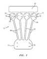
- FIG. 5shows a perspective view a perspective view of the valve repair device held by a valve repair instrument
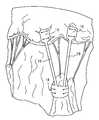
- FIG. 6shows a perspective view a perspective view of the valve repair device held by a valve repair instrument with a muscle portion sutured to the papillary muscle;
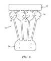
- FIG. 7shows a perspective view of the valve repair device sutured in the mitral valve using one partition member and chord.
- FIG. 8shows a perspective view of the valve repair device sutured in the mitral valve using two partition members and two chords
- FIG. 9shows a top view of another embodiment of the valve repair device.
- Valve repair device 10in accordance with the present invention is illustrated.
- Valve repair device 10includes a leaflet portion 12 and a muscle portion 14 .
- the leaflet portionincludes at least one partition member 16 which is attached to the leaflet of the heart.
- Chords 18extend from the leaflet portion 12 and connect leaflet portion 12 to amuscle portion 14 .
- Valve repair device 10is a thin flexible element preferably constructed of a biocompatible cloth.
- valve repair deviceis constructed of a plastic reinforced cloth, such as expanded polytetraflouroethylene.
- Gor-Tex®produced by W. L. Gore and Associates, Inc., Flagstaff, Ariz., is an example of a suitable biocompatible cloth made from expanded polytetraflouroethylene.
- Valve repair deviceis generally of a uniform thickness and constructed from a single sheet of biocompatible cloth.
- Leaflet portion 12provides an anchor to the leaflet of a valve of the heart for chords 18 , and may essentially replicate the leaflet, if the leaflet is diseased.
- Leaflet portion 12is sized for repair of the anterior or posterior leaflet, and more specifically, to repair elongated or ruptured chordae of a floppy valve, either a posterior or anterior leaflet.
- End portion 20may be placed in a valve repair instrument, such as the valve repair instrument disclosed in U.S. application Ser. No. 2013-0013056-A1, to aid in securing the valve repair device to the instrument.
- End 20is removed as well as excess partition members 16 as needed to size the valve repair device 10 to the patient. More preferably, partition members 16 include openings 22 for suturing leaflet portion 12 to the leaflet of the heart.
- Muscle portion 14may include openings 24 for suturing muscle portion 14 to the papillary muscle of the heart. Muscle portion 14 provides an anchor for chords 18 to the papillary muscle. Muscle portion 14 may be cylindrically shaped to surround the papillary muscle. Chords 18 connect leaflet portion 12 and muscle portion 14 and function as the chordae tendineae as explained in greater detail below
- chordae tendineaeare attached to the respective posterior leaflet or anterior leaflet and connect the leaflet to the papillary muscle.
- the diseased portion of the valveis excised, such as the elongated portion of a chordae or a ruptured chordae, and the remaining leaflet material is then sutured together. If the chordae tendoneae is diseased, it may also be excised, with sutures connecting the leaflet to the papillary muscle.
- valve repair device 10is directly sutured to the mitral valve by suturing partition members 16 of leaflet portion 12 to the affected leaflet and muscle portion 14 to the affected papillary muscle so that chords 18 replicate the chordae tendineae. End portion 20 as well as any excess partition members 16 are cut from leaflet portion 12 to an appropriate size to cover the excised diseased material, thereby reducing the impact to the leaflet and its function that is associated with the prior art method of reconnecting the leaflet at the point of excision.
- the physicianwill assess the degree of disease, and determine the extent of the repair to the mitral valve needed.
- the surgeonwill first excise the diseased material, such as the elongated scallop portion of a leaflet, the perforated portion of the leaflet, the affected chordae tendineae, etc.
- An annular ringmay be used to reinforce the mitral valve.
- the surgeonwill determine the size of the valve repair device 10 needed to effectuate the repair and may reduce leaflet 12 by cutting, such as illustrated by lines 26 and 28 , unneeded partition members 16 and end portion 20 from leaflet portion 12 .
- the physicianmay also cut unneeded chords 18 .
- the surgeonsutures leaflet portion 12 over the affected area of the posterior or anterior leaflet such that end 30 of a partition member 16 is positioned near the edge of the leaflet with suture 32 .
- the surgeonsutures muscle portion 14 to the papillary muscle with suture 34 .
- the surgeonPrior to suturing muscle portion 14 to the papillary muscle, the surgeon must determine the distance or location to position muscle portion 14 to the papillary muscle, for example as illustrated in U.S. Pat. No. 6,997,950, so that the leaflet is positioned properly to open and close effectively. Failure to accurately determine the location for muscle portion 14 may result in an ineffective repair, causing prolapse of the leaflet, which in turn may cause the valve to leak.
- the surgeonmay estimate the needed chord length by comparing the relative length of the adjoining “reference” chords.
- the chordae tendeneaecomprise the marginal chord, the secondary chord and the basilar chord.
- the marginal chordis located adjacent the margin or edge of the respective anterior or posterior leaflet.
- the basilar chordis located adjacent to the area adjoining the annulus of the mitral valve and the secondary chord is positioned between the marginal chord and the basilar chord.
- Disease in the mitral valveis typically associated with the marginal chord.
- the surgeonmay approximate the needed chord length, by positioning the valve repair device adjacent to a normal marginal chord. The surgeon may also reference the chord length of the opposing anterior or posterior leaflet chordae tendeneae.
- the surgeonwill suture a holding stitch or a stay suture between the anterior and posterior leaflets at the level of adjoining normal chordae to obtain accurate approximation of the desired chord length.
- the surgeonmay suture muscle portion 14 to the papillary muscle to achieve the desired location to effectuate a repair.
- Valve repair device 10may be used to repair the anterior leaflet or the posterior leaflet, by positioning leaflet portion such that end 30 is positioned along the outer edge of the leaflet to be repaired. Moreover, valve repair device 10 may be offered in a variety of sizes and specifically in a kit form. Prior to undertaking the repair of the mitral valve, the surgeon will typically be acquainted with patient's specific physiology. During the open-heart operation, time is an important factor, and a surgeon may be confronted with an unknown defect in the valve. In use, valve repair device 10 eliminates the bulky process of affixing sutures from the papillary muscle to the respective posterior or anterior leaflet. Leaflet portion 12 is sutured directly to the leaflet using openings 22 provided in partition members 16 .
- the surgeonmay easily modify the size of valve repair device 10 by cutting excess partition members 16 from leaflet 12 and/or cutting muscle portion 14 , saving time. Moreover, the ease of attaching leaflet portion 12 to the leaflet as well as attaching muscle portion 14 to the papillary muscle increases the surgeon's ability to obtain the effective opening and closure of the valve, as the tedious and more imprecise process of attaching sutures as chords is eliminated.
- the anterior leaflet of the mitral valveis particularly difficult to repair given its proximity to the aortic valve. The instant invention allows the surgeon to suture leaflet portion to the anterior leaflet without affecting the aortic valve.
- a valve repair instrument 40such as the valve repair instrument disclosed in U.S. application Ser. No. 2013-0013056-A1, maintains the valve repair device 10 is an expanded position.
- the distal end 42 of the instrument 40is placed such that the muscle portion 14 of valve repair device 10 is adjacent to the papillary muscle.
- Muscle portion 14is maintained in a semi-cylindrical shape, allowing the surgeon to place the muscle portion 14 to partially surround the papillary muscle.
- the instrumentis positioned such that the muscle portion 14 is positioned for suturing to the papillary muscle via sutures 34 .
- chords attaching the muscle portion 14 to instrument 40are then severed, separating the muscle portion 14 of the valve repair device 10 from the instrument 40 .
- Leaflet portion 12is then positioned.
- Excess chords 18 and partition members 16may be cut to size valve repair device 10 as need.
- valve repair device 10may be sized with a single partition member 16 of leaflet portion 12 such that a single chord 18 connects leaflet portion 12 to muscle portion 14 , for example when the degree of disease and the extent of the repair is minimal.
- valve repair device 10may be sized asymmetrically with two partition members 16 of leaflet portion 12 such that two chords 18 connect leaflet portion 12 to muscle portion 14 , to accommodate an symmetric repair. In this manner, the number and types of repairs that may be used with the present invention is greatly enhanced.
- valve repair device 10may be offered in a variety of sizes and specifically in a kit form.
- Valve repair device 50includes leaflet portion 52 and muscle portion 54 as in the first embodiment. Is this embodiment, partition members 56 vary in size. The center partition members 56 are slightly larger than the outer partition members 56 to provide a valve repair device 56 for larger excisions.
Landscapes
- Health & Medical Sciences (AREA)
- Cardiology (AREA)
- Oral & Maxillofacial Surgery (AREA)
- Transplantation (AREA)
- Engineering & Computer Science (AREA)
- Biomedical Technology (AREA)
- Heart & Thoracic Surgery (AREA)
- Vascular Medicine (AREA)
- Life Sciences & Earth Sciences (AREA)
- Animal Behavior & Ethology (AREA)
- General Health & Medical Sciences (AREA)
- Public Health (AREA)
- Veterinary Medicine (AREA)
- Prostheses (AREA)
Abstract
Description
Claims (10)
Priority Applications (1)
| Application Number | Priority Date | Filing Date | Title |
|---|---|---|---|
| US14/039,568US9248018B2 (en) | 2013-09-27 | 2013-09-27 | Valve repair device |
Applications Claiming Priority (1)
| Application Number | Priority Date | Filing Date | Title |
|---|---|---|---|
| US14/039,568US9248018B2 (en) | 2013-09-27 | 2013-09-27 | Valve repair device |
Publications (2)
| Publication Number | Publication Date |
|---|---|
| US20150094800A1 US20150094800A1 (en) | 2015-04-02 |
| US9248018B2true US9248018B2 (en) | 2016-02-02 |
Family
ID=52740891
Family Applications (1)
| Application Number | Title | Priority Date | Filing Date |
|---|---|---|---|
| US14/039,568Active - Reinstated2034-01-09US9248018B2 (en) | 2013-09-27 | 2013-09-27 | Valve repair device |
Country Status (1)
| Country | Link |
|---|---|
| US (1) | US9248018B2 (en) |
Cited By (3)
| Publication number | Priority date | Publication date | Assignee | Title |
|---|---|---|---|---|
| US10945718B2 (en) | 2014-09-17 | 2021-03-16 | Cardiomech As | Device for heart repair |
| US11357499B2 (en) | 2015-08-18 | 2022-06-14 | Lsi Solutions, Inc. | Apparatus for mitral valve repair and methods thereof |
| US12350157B2 (en) | 2018-11-29 | 2025-07-08 | Cardiomech As | Device for heart repair |
Families Citing this family (78)
| Publication number | Priority date | Publication date | Assignee | Title |
|---|---|---|---|---|
| US8608797B2 (en) | 2005-03-17 | 2013-12-17 | Valtech Cardio Ltd. | Mitral valve treatment techniques |
| US11259924B2 (en) | 2006-12-05 | 2022-03-01 | Valtech Cardio Ltd. | Implantation of repair devices in the heart |
| US9883943B2 (en) | 2006-12-05 | 2018-02-06 | Valtech Cardio, Ltd. | Implantation of repair devices in the heart |
| US11660190B2 (en) | 2007-03-13 | 2023-05-30 | Edwards Lifesciences Corporation | Tissue anchors, systems and methods, and devices |
| US8382829B1 (en) | 2008-03-10 | 2013-02-26 | Mitralign, Inc. | Method to reduce mitral regurgitation by cinching the commissure of the mitral valve |
| US8241351B2 (en) | 2008-12-22 | 2012-08-14 | Valtech Cardio, Ltd. | Adjustable partial annuloplasty ring and mechanism therefor |
| US10517719B2 (en) | 2008-12-22 | 2019-12-31 | Valtech Cardio, Ltd. | Implantation of repair devices in the heart |
| WO2010073246A2 (en) | 2008-12-22 | 2010-07-01 | Valtech Cardio, Ltd. | Adjustable annuloplasty devices and adjustment mechanisms therefor |
| US8911494B2 (en) | 2009-05-04 | 2014-12-16 | Valtech Cardio, Ltd. | Deployment techniques for annuloplasty ring |
| US8715342B2 (en) | 2009-05-07 | 2014-05-06 | Valtech Cardio, Ltd. | Annuloplasty ring with intra-ring anchoring |
| US8353956B2 (en) | 2009-02-17 | 2013-01-15 | Valtech Cardio, Ltd. | Actively-engageable movement-restriction mechanism for use with an annuloplasty structure |
| US9968452B2 (en) | 2009-05-04 | 2018-05-15 | Valtech Cardio, Ltd. | Annuloplasty ring delivery cathethers |
| US9180007B2 (en) | 2009-10-29 | 2015-11-10 | Valtech Cardio, Ltd. | Apparatus and method for guide-wire based advancement of an adjustable implant |
| US10098737B2 (en) | 2009-10-29 | 2018-10-16 | Valtech Cardio, Ltd. | Tissue anchor for annuloplasty device |
| US8734467B2 (en) | 2009-12-02 | 2014-05-27 | Valtech Cardio, Ltd. | Delivery tool for implantation of spool assembly coupled to a helical anchor |
| US9307980B2 (en) | 2010-01-22 | 2016-04-12 | 4Tech Inc. | Tricuspid valve repair using tension |
| US8475525B2 (en) | 2010-01-22 | 2013-07-02 | 4Tech Inc. | Tricuspid valve repair using tension |
| US10058323B2 (en) | 2010-01-22 | 2018-08-28 | 4 Tech Inc. | Tricuspid valve repair using tension |
| EP3345573B1 (en) | 2011-06-23 | 2020-01-29 | Valtech Cardio, Ltd. | Closure element for use with annuloplasty structure |
| US10792152B2 (en) | 2011-06-23 | 2020-10-06 | Valtech Cardio, Ltd. | Closed band for percutaneous annuloplasty |
| EP2734157B1 (en)* | 2011-07-21 | 2018-09-05 | 4Tech Inc. | Apparatus for tricuspid valve repair using tension |
| US8858623B2 (en) | 2011-11-04 | 2014-10-14 | Valtech Cardio, Ltd. | Implant having multiple rotational assemblies |
| EP3656434B1 (en) | 2011-11-08 | 2021-10-20 | Valtech Cardio, Ltd. | Controlled steering functionality for implant-delivery tool |
| EP2881083B1 (en) | 2011-12-12 | 2017-03-22 | David Alon | Heart valve repair device |
| US8961594B2 (en) | 2012-05-31 | 2015-02-24 | 4Tech Inc. | Heart valve repair system |
| US9216018B2 (en) | 2012-09-29 | 2015-12-22 | Mitralign, Inc. | Plication lock delivery system and method of use thereof |
| WO2014064694A2 (en) | 2012-10-23 | 2014-05-01 | Valtech Cardio, Ltd. | Controlled steering functionality for implant-delivery tool |
| EP2911593B1 (en) | 2012-10-23 | 2020-03-25 | Valtech Cardio, Ltd. | Percutaneous tissue anchor techniques |
| WO2014087402A1 (en) | 2012-12-06 | 2014-06-12 | Valtech Cardio, Ltd. | Techniques for guide-wire based advancement of a tool |
| CN105007832B (en) | 2013-01-09 | 2018-01-23 | 4科技有限公司 | Organize ancora equipment |
| EP2961351B1 (en) | 2013-02-26 | 2018-11-28 | Mitralign, Inc. | Devices for percutaneous tricuspid valve repair |
| US10449333B2 (en) | 2013-03-14 | 2019-10-22 | Valtech Cardio, Ltd. | Guidewire feeder |
| US9907681B2 (en) | 2013-03-14 | 2018-03-06 | 4Tech Inc. | Stent with tether interface |
| CN105283214B (en) | 2013-03-15 | 2018-10-16 | 北京泰德制药股份有限公司 | Translate conduit, system and its application method |
| US10070857B2 (en) | 2013-08-31 | 2018-09-11 | Mitralign, Inc. | Devices and methods for locating and implanting tissue anchors at mitral valve commissure |
| WO2015059699A2 (en) | 2013-10-23 | 2015-04-30 | Valtech Cardio, Ltd. | Anchor magazine |
| WO2015063580A2 (en) | 2013-10-30 | 2015-05-07 | 4Tech Inc. | Multiple anchoring-point tension system |
| US10052095B2 (en) | 2013-10-30 | 2018-08-21 | 4Tech Inc. | Multiple anchoring-point tension system |
| US10022114B2 (en) | 2013-10-30 | 2018-07-17 | 4Tech Inc. | Percutaneous tether locking |
| US9610162B2 (en) | 2013-12-26 | 2017-04-04 | Valtech Cardio, Ltd. | Implantation of flexible implant |
| US9572666B2 (en) | 2014-03-17 | 2017-02-21 | Evalve, Inc. | Mitral valve fixation device removal devices and methods |
| US10390943B2 (en) | 2014-03-17 | 2019-08-27 | Evalve, Inc. | Double orifice device for transcatheter mitral valve replacement |
| WO2015193728A2 (en) | 2014-06-19 | 2015-12-23 | 4Tech Inc. | Cardiac tissue cinching |
| EP3922213A1 (en) | 2014-10-14 | 2021-12-15 | Valtech Cardio, Ltd. | Leaflet-restraining techniques |
| US9907547B2 (en) | 2014-12-02 | 2018-03-06 | 4Tech Inc. | Off-center tissue anchors |
| US20160256269A1 (en) | 2015-03-05 | 2016-09-08 | Mitralign, Inc. | Devices for treating paravalvular leakage and methods use thereof |
| CN107847320B (en) | 2015-04-30 | 2020-03-17 | 瓦尔泰克卡迪欧有限公司 | Valvuloplasty techniques |
| US10828160B2 (en) | 2015-12-30 | 2020-11-10 | Edwards Lifesciences Corporation | System and method for reducing tricuspid regurgitation |
| US9693864B1 (en)* | 2016-03-30 | 2017-07-04 | Mohammad Naficy | Heart surgery apparatus |
| CN105852916B (en) | 2016-04-14 | 2018-02-06 | 上海甲悦医疗器械有限公司 | A kind of bicuspid valve flexibility closure plate occluder and method for implantation being implanted into through the apex of the heart |
| CN105726072B (en)* | 2016-04-14 | 2018-02-27 | 江苏大学 | A kind of bicuspid valve air bag closure plate occluder and method for implantation being implanted into through the apex of the heart |
| US10702274B2 (en) | 2016-05-26 | 2020-07-07 | Edwards Lifesciences Corporation | Method and system for closing left atrial appendage |
| US10736632B2 (en) | 2016-07-06 | 2020-08-11 | Evalve, Inc. | Methods and devices for valve clip excision |
| GB201611910D0 (en) | 2016-07-08 | 2016-08-24 | Valtech Cardio Ltd | Adjustable annuloplasty device with alternating peaks and troughs |
| US11071564B2 (en) | 2016-10-05 | 2021-07-27 | Evalve, Inc. | Cardiac valve cutting device |
| US10363138B2 (en) | 2016-11-09 | 2019-07-30 | Evalve, Inc. | Devices for adjusting the curvature of cardiac valve structures |
| US10426616B2 (en) | 2016-11-17 | 2019-10-01 | Evalve, Inc. | Cardiac implant delivery system |
| CN106409263B (en)* | 2016-11-29 | 2020-05-22 | 海信视像科技股份有限公司 | Liquid crystal panel and line short-circuit protection method thereof |
| US11045627B2 (en) | 2017-04-18 | 2021-06-29 | Edwards Lifesciences Corporation | Catheter system with linear actuation control mechanism |
| US10835221B2 (en) | 2017-11-02 | 2020-11-17 | Valtech Cardio, Ltd. | Implant-cinching devices and systems |
| US11135062B2 (en) | 2017-11-20 | 2021-10-05 | Valtech Cardio Ltd. | Cinching of dilated heart muscle |
| CN116531147A (en) | 2018-01-24 | 2023-08-04 | 爱德华兹生命科学创新(以色列)有限公司 | Contraction of annuloplasty structures |
| EP4248904A3 (en) | 2018-01-26 | 2023-11-29 | Edwards Lifesciences Innovation (Israel) Ltd. | Techniques for facilitating heart valve tethering and chord replacement |
| US11969345B2 (en) | 2018-07-11 | 2024-04-30 | Children's Medical Center Corporation | Repair device for heart valve repair |
| EP3820406B1 (en) | 2018-07-12 | 2023-12-20 | Edwards Lifesciences Innovation (Israel) Ltd. | Annuloplasty systems and locking tools therefor |
| US12102531B2 (en) | 2018-10-22 | 2024-10-01 | Evalve, Inc. | Tissue cutting systems, devices and methods |
| SG11202112651QA (en) | 2019-05-29 | 2021-12-30 | Valtech Cardio Ltd | Tissue anchor handling systems and methods |
| US12364606B2 (en) | 2019-07-23 | 2025-07-22 | Edwards Lifesciences Innovation (Israel) Ltd. | Fluoroscopic visualization of heart valve anatomy |
| JP2022546160A (en) | 2019-08-30 | 2022-11-04 | エドワーズ ライフサイエンシーズ イノベーション (イスラエル) リミテッド | Anchor channel tip |
| EP4034042A1 (en) | 2019-09-25 | 2022-08-03 | Cardiac Implants LLC | Cardiac valve annulus reduction system |
| EP4193934A1 (en) | 2019-10-29 | 2023-06-14 | Edwards Lifesciences Innovation (Israel) Ltd. | Annuloplasty and tissue anchor technologies |
| US12171486B2 (en) | 2020-05-06 | 2024-12-24 | Evalve, Inc. | Devices and methods for clip separation |
| US12171485B2 (en) | 2020-05-06 | 2024-12-24 | Evalve, Inc. | Systems and methods for leaflet cutting using a hook catheter |
| US12178444B2 (en) | 2020-05-06 | 2024-12-31 | Evalve, Inc. | Clip removal systems and methods |
| US12414811B2 (en) | 2020-05-06 | 2025-09-16 | Evalve, Inc. | Devices and methods for leaflet cutting |
| US12048448B2 (en) | 2020-05-06 | 2024-07-30 | Evalve, Inc. | Leaflet grasping and cutting device |
| US12023247B2 (en) | 2020-05-20 | 2024-07-02 | Edwards Lifesciences Corporation | Reducing the diameter of a cardiac valve annulus with independent control over each of the anchors that are launched into the annulus |
| CA3182316A1 (en) | 2020-06-19 | 2021-12-23 | Edwards Lifesciences Innovation (Israel) Ltd. | Self-stopping tissue anchors |
Citations (2)
| Publication number | Priority date | Publication date | Assignee | Title |
|---|---|---|---|---|
| US6726706B2 (en)* | 2001-06-26 | 2004-04-27 | Steven Dominguez | Suture tape and method for use |
| US20130053951A1 (en)* | 2010-03-19 | 2013-02-28 | Xavier Ruyra Baliarda | Prosthetic band, in particular for repairing a mitral valve |
- 2013
- 2013-09-27USUS14/039,568patent/US9248018B2/enactiveActive - Reinstated
Patent Citations (2)
| Publication number | Priority date | Publication date | Assignee | Title |
|---|---|---|---|---|
| US6726706B2 (en)* | 2001-06-26 | 2004-04-27 | Steven Dominguez | Suture tape and method for use |
| US20130053951A1 (en)* | 2010-03-19 | 2013-02-28 | Xavier Ruyra Baliarda | Prosthetic band, in particular for repairing a mitral valve |
Cited By (5)
| Publication number | Priority date | Publication date | Assignee | Title |
|---|---|---|---|---|
| US10945718B2 (en) | 2014-09-17 | 2021-03-16 | Cardiomech As | Device for heart repair |
| US11253247B2 (en) | 2014-09-17 | 2022-02-22 | Cardiomech As | Device for heart repair |
| US11357499B2 (en) | 2015-08-18 | 2022-06-14 | Lsi Solutions, Inc. | Apparatus for mitral valve repair and methods thereof |
| US11903578B2 (en) | 2015-08-18 | 2024-02-20 | Lsi Solutions, Inc. | Apparatus for mitral valve repair and methods thereof |
| US12350157B2 (en) | 2018-11-29 | 2025-07-08 | Cardiomech As | Device for heart repair |
Also Published As
| Publication number | Publication date |
|---|---|
| US20150094800A1 (en) | 2015-04-02 |
Similar Documents
| Publication | Publication Date | Title |
|---|---|---|
| US9248018B2 (en) | Valve repair device | |
| US6997950B2 (en) | Valve repair device | |
| US6312464B1 (en) | Method of implanting a stentless cardiac valve prosthesis | |
| US10166101B2 (en) | Methods for repairing mitral valves | |
| CA2561716C (en) | Annuloplasty ring for mitral valve prolapse | |
| US20050004665A1 (en) | Annuloplasty rings and methods for repairing cardiac valves | |
| US6517576B2 (en) | Implantable patch prosthesis having one or more cusps for improved competency | |
| US7591847B2 (en) | Stentless bioprosthetic valve having chordae for replacing a mitral valve | |
| JP4594316B2 (en) | Annuloplasty ring for repair of abnormal mitral valve | |
| US20080319541A1 (en) | Devices and methods for repairing cardiac valves | |
| US9486315B2 (en) | Valve repair instrument | |
| CN101652113B (en) | Separate aortic artificial valve leaflet and template for preparation thereof | |
| Schwartz et al. | The role of annuloplasty in mitral valve repair | |
| AU2011235960B2 (en) | Devices and methods for repairing cardiac valves | |
| US20110034998A1 (en) | Annuloplasty tubes | |
| Muehrcke et al. | The Cleveland Clinic Experience with Mitral Valve Repair | |
| EUROPIAN | Porcine mitral stentless valve mid-term clinical results1 |
Legal Events
| Date | Code | Title | Description |
|---|---|---|---|
| STCF | Information on status: patent grant | Free format text:PATENTED CASE | |
| FEPP | Fee payment procedure | Free format text:MAINTENANCE FEE REMINDER MAILED (ORIGINAL EVENT CODE: REM.); ENTITY STATUS OF PATENT OWNER: SMALL ENTITY | |
| LAPS | Lapse for failure to pay maintenance fees | Free format text:PATENT EXPIRED FOR FAILURE TO PAY MAINTENANCE FEES (ORIGINAL EVENT CODE: EXP.); ENTITY STATUS OF PATENT OWNER: SMALL ENTITY | |
| FP | Lapsed due to failure to pay maintenance fee | Effective date:20200202 | |
| FEPP | Fee payment procedure | Free format text:SURCHARGE, PETITION TO ACCEPT PYMT AFTER EXP, UNINTENTIONAL (ORIGINAL EVENT CODE: M3558); ENTITY STATUS OF PATENT OWNER: MICROENTITY Free format text:ENTITY STATUS SET TO MICRO (ORIGINAL EVENT CODE: MICR); ENTITY STATUS OF PATENT OWNER: MICROENTITY Free format text:PETITION RELATED TO MAINTENANCE FEES GRANTED (ORIGINAL EVENT CODE: PMFG); ENTITY STATUS OF PATENT OWNER: MICROENTITY Free format text:PETITION RELATED TO MAINTENANCE FEES FILED (ORIGINAL EVENT CODE: PMFP); ENTITY STATUS OF PATENT OWNER: MICROENTITY | |
| MAFP | Maintenance fee payment | Free format text:PAYMENT OF MAINTENANCE FEE, 4TH YEAR, MICRO ENTITY (ORIGINAL EVENT CODE: M3551); ENTITY STATUS OF PATENT OWNER: MICROENTITY Year of fee payment:4 | |
| PRDP | Patent reinstated due to the acceptance of a late maintenance fee | Effective date:20210301 | |
| STCF | Information on status: patent grant | Free format text:PATENTED CASE | |
| MAFP | Maintenance fee payment | Free format text:PAYMENT OF MAINTENANCE FEE, 8TH YEAR, MICRO ENTITY (ORIGINAL EVENT CODE: M3552); ENTITY STATUS OF PATENT OWNER: MICROENTITY Year of fee payment:8 |