US9247962B2 - Laminar hook insertion device - Google Patents
Laminar hook insertion deviceDownload PDFInfo
- Publication number
- US9247962B2 US9247962B2US13/209,542US201113209542AUS9247962B2US 9247962 B2US9247962 B2US 9247962B2US 201113209542 AUS201113209542 AUS 201113209542AUS 9247962 B2US9247962 B2US 9247962B2
- Authority
- US
- United States
- Prior art keywords
- hook
- elongate body
- actuation rod
- laminar
- assembly according
- Prior art date
- Legal status (The legal status is an assumption and is not a legal conclusion. Google has not performed a legal analysis and makes no representation as to the accuracy of the status listed.)
- Active, expires
Links
Images


Classifications
- A—HUMAN NECESSITIES
- A61—MEDICAL OR VETERINARY SCIENCE; HYGIENE
- A61B—DIAGNOSIS; SURGERY; IDENTIFICATION
- A61B17/00—Surgical instruments, devices or methods
- A61B17/56—Surgical instruments or methods for treatment of bones or joints; Devices specially adapted therefor
- A61B17/58—Surgical instruments or methods for treatment of bones or joints; Devices specially adapted therefor for osteosynthesis, e.g. bone plates, screws or setting implements
- A61B17/68—Internal fixation devices, including fasteners and spinal fixators, even if a part thereof projects from the skin
- A61B17/70—Spinal positioners or stabilisers, e.g. stabilisers comprising fluid filler in an implant
- A61B17/7074—Tools specially adapted for spinal fixation operations other than for bone removal or filler handling
- A61B17/7076—Tools specially adapted for spinal fixation operations other than for bone removal or filler handling for driving, positioning or assembling spinal clamps or bone anchors specially adapted for spinal fixation
- A—HUMAN NECESSITIES
- A61—MEDICAL OR VETERINARY SCIENCE; HYGIENE
- A61B—DIAGNOSIS; SURGERY; IDENTIFICATION
- A61B17/00—Surgical instruments, devices or methods
- A61B17/56—Surgical instruments or methods for treatment of bones or joints; Devices specially adapted therefor
- A—HUMAN NECESSITIES
- A61—MEDICAL OR VETERINARY SCIENCE; HYGIENE
- A61B—DIAGNOSIS; SURGERY; IDENTIFICATION
- A61B17/00—Surgical instruments, devices or methods
- A61B17/56—Surgical instruments or methods for treatment of bones or joints; Devices specially adapted therefor
- A61B17/58—Surgical instruments or methods for treatment of bones or joints; Devices specially adapted therefor for osteosynthesis, e.g. bone plates, screws or setting implements
- A61B17/68—Internal fixation devices, including fasteners and spinal fixators, even if a part thereof projects from the skin
- A61B17/70—Spinal positioners or stabilisers, e.g. stabilisers comprising fluid filler in an implant
- A61B17/7001—Screws or hooks combined with longitudinal elements which do not contact vertebrae
- A61B17/7044—Screws or hooks combined with longitudinal elements which do not contact vertebrae also having plates, staples or washers bearing on the vertebrae
- A—HUMAN NECESSITIES
- A61—MEDICAL OR VETERINARY SCIENCE; HYGIENE
- A61B—DIAGNOSIS; SURGERY; IDENTIFICATION
- A61B17/00—Surgical instruments, devices or methods
- A61B17/56—Surgical instruments or methods for treatment of bones or joints; Devices specially adapted therefor
- A61B17/58—Surgical instruments or methods for treatment of bones or joints; Devices specially adapted therefor for osteosynthesis, e.g. bone plates, screws or setting implements
- A61B17/68—Internal fixation devices, including fasteners and spinal fixators, even if a part thereof projects from the skin
- A61B17/70—Spinal positioners or stabilisers, e.g. stabilisers comprising fluid filler in an implant
- A61B17/7001—Screws or hooks combined with longitudinal elements which do not contact vertebrae
- A61B17/7032—Screws or hooks with U-shaped head or back through which longitudinal rods pass
- A—HUMAN NECESSITIES
- A61—MEDICAL OR VETERINARY SCIENCE; HYGIENE
- A61B—DIAGNOSIS; SURGERY; IDENTIFICATION
- A61B17/00—Surgical instruments, devices or methods
- A61B17/56—Surgical instruments or methods for treatment of bones or joints; Devices specially adapted therefor
- A61B17/58—Surgical instruments or methods for treatment of bones or joints; Devices specially adapted therefor for osteosynthesis, e.g. bone plates, screws or setting implements
- A61B17/68—Internal fixation devices, including fasteners and spinal fixators, even if a part thereof projects from the skin
- A61B17/80—Cortical plates, i.e. bone plates; Instruments for holding or positioning cortical plates, or for compressing bones attached to cortical plates
- A61B17/808—Instruments for holding or positioning bone plates, or for adjusting screw-to-plate locking mechanisms
- A—HUMAN NECESSITIES
- A61—MEDICAL OR VETERINARY SCIENCE; HYGIENE
- A61B—DIAGNOSIS; SURGERY; IDENTIFICATION
- A61B17/00—Surgical instruments, devices or methods
- A61B17/56—Surgical instruments or methods for treatment of bones or joints; Devices specially adapted therefor
- A61B2017/564—Methods for bone or joint treatment
Definitions
- the present disclosurerelates to an orthopedic surgical device, and more particularly, to a laminar hook insertion device.
- spinal implant systemshave been developed to achieve immobilization of vertebral bodies of the spine in a particular spatial relationship to correct spinal irregularities and to restore stability to traumatized areas of the spine.
- These spinal implant systemsmay be classified as anterior, posterior, or lateral implants.
- lateral and anterior assembliesare coupled to the anterior portion of the spine, which is the sequence of vertebral bodies.
- Posterior implantsare attached to the back of the spinal column, generally by coupling to the pedicles via screws, or by means of hooks which attach under the lamina and entering into the central canal.
- the implantsgenerally include elongate support rod elements which are coupled to the screws or hooks to immobilize several sequential vertebrae, for example to hold them stable so that adjacent bones may be fused with bone graft.
- Such hook and rod assembliesgenerally include a plurality of hooks having rounded blade portions, flat extending members of which are inserted posteriorly under the lamina between the transverse process and the spinous process.
- the hooksfurther include upper body portions to which the support rod may be coupled.
- the rodextends along the axis of the spine, coupling to each of a plurality of hooks via receiving portions of their bodies. The aligning influence of the rod forces the spine to which it is affixed, to conform to a more proper shape.
- a surgical hook insertion deviceincluding an elongate body and an actuation assembly.
- the elongate bodydefines a lumen therethrough.
- the elongate bodyincludes a retaining portion configured and dimensioned to releasably retain a laminar hook therein.
- the actuation assemblyincludes an actuation rod and an actuator member. The actuation rod is slideably disposed within the lumen of the elongate body.
- the actuator memberis operatively coupled with the actuation rod and is slideably mounted on the elongate body, wherein the actuation assembly is transitionable between a first position in which a portion of the actuation rod engages the laminar hook releasably disposed in the retaining portion and a second position in which the actuation rod disengages the laminar hook.
- the surgical hook insertion devicemay further include a biasing member, wherein the biasing member urges the actuation assembly to the first position.
- the elongate bodymay define a cavity configured and dimensioned to enable sliding movement of a pin coupling the actuation rod and the actuator member therein.
- the retaining portion of the elongate bodymay include a seating protrusion adapted to engage and retain a hooked portion of the laminar hook.
- the seating protrusionmay conform to the contour of the hooked portion of the laminar hook.
- the retaining portionmay include a pair of support plates engaging lateral sides of the seating protrusion. Each of the pair of support plates may define a groove configured to retain a portion of the laminar hook therein.
- the lumen defined in the elongate bodymay include a first portion and a second portion.
- the first portion of the lumenmay have a larger diameter than that of the second portion.
- the actuation rodmay include a first portion and a second portion.
- the first portion of the actuation rodmay have a larger diameter than that of the second portion.
- the first and second portions of the lumenmay be configured and dimensioned to receive the first and second portions of the actuation rod therein, respectively.
- the surgical hook insertion devicemay further include a handle member defining a channel therethrough.
- the channelmay be dimensioned to receive the first portion of the actuation rod.
- the actuator membermay be disposed adjacent the handle member.
- a surgical implant insertion assemblyincluding a handle member, an elongate body, an actuation assembly, and a laminar hook.
- the handle memberdefines a channel therethrough.
- the elongate bodydefines a lumen therethrough.
- the elongate bodyis disposed at least partially within the channel of the handle assembly.
- the lumenis in communication with the channel.
- the elongate bodyincludes a retaining portion adapted to releasably retain a laminar hook therein.
- the actuation assemblyincludes an actuation rod and an actuator member.
- the actuation rodis slideably disposed within the lumen of the elongate body.
- the actuator memberis operatively coupled with the actuation rod.
- the actuator memberis slideably mounted on the elongate body assembly.
- the laminar hookincludes a hooked portion and a head portion.
- the hook portiondefines a recess configured and dimensioned to releasably engage a portion of the actuation rod, wherein the actuation assembly is transitionable between a first position in which a distal portion of the actuation rod engages the laminar hook in the retaining portion and a second position in which the actuation rod disengages the laminar hook.
- the surgical implant insertion assemblymay further include a biasing member disposed in a proximal portion of the elongate body, wherein the biasing member urges the actuation assembly to the first position.
- the elongate bodymay define a cavity adjacent the handle member, the cavity configured and dimensioned to enable sliding movement of a pin coupling the actuation rod with the actuator member.
- the retaining portion of the elongate bodymay include a seating protrusion adapted to engage and retain a hooked portion of the laminar hook.
- the seating protrusionmay conform to the contour of the hooked portion of the laminar hook.
- the retaining portionmay include a pair of support plates engaging lateral sides of the seating protrusion. Each of the pair of support plates may define a groove configured to retain a portion of the laminar hook therein.
- the lumen defined in the elongate bodymay include a first portion and a second portion.
- the first portion of the lumenmay have a larger diameter than that of the second portion.
- the actuation rodmay include a first portion and a second portion.
- the first portion of the actuation rodmay have a larger diameter than that of the second portion.
- the first and second portions of the lumenmay be configured and dimensioned to receive the first and second portions of the actuation rod therein, respectively.
- the head portion of the laminar hookmay define a bore configured and dimensioned to receive a bone screw therein.
- a method of stabilizing the spineincludes providing a surgical hook insertion device including an elongate body and an actuation rod.
- the elongate bodydefines a lumen therethrough.
- the elongate bodyhas a retaining portion configured and dimensioned to releasably retain a laminar hook therein.
- the actuation rodis slideably disposed within the lumen of the elongate body, wherein the actuation rod is transitionable between a first position in which a portion of the actuation rod engages the laminar hook releasably disposed in the retaining portion and a second position in which the actuation rod disengages the laminar hook.
- the methodfurther includes positioning the laminar hook to a bone, implanting a bone screw into the bone through the laminar hook, inserting a connecting rod into a connecting rod slot in the bone screw, and locking the connecting rod in the connecting rod slot in the bone screw.
- the methodmay further include bending the connecting rod prior to inserting a connecting rod into a connecting rod slot in the bone screw.
- bending the connecting rodmay include bending the connecting rod to conform to a desire contour of the spine.
- the spinal hook insertion devicemay further include a biasing member disposed in a proximal portion of the elongate body, wherein the biasing member urges the actuation rod to the first position.
- the spinal hook insertion devicemay include an actuator member operatively coupled with the actuation rod and slideably mounted on the elongate body.
- the spinal hook insertion devicemay further include a laminar hook including an arched portion and a head portion. The arched portion may define a recess configured and dimensioned to releasably engage a portion of the actuation rod.
- the head portion of the laminar hookmay include a threaded bore configured and dimensioned to receive therethrough the bone screw.
- implanting a bone screw into the bone through the laminar hookmay include inserting the bone screw through the threaded bore defined in the head portion of the laminar hook.
- Positioning the laminar hook to a bonemay include positioning the arched portion of the laminar hook on an undersurface of the lamina.
- positioning the laminar hook to a bonemay include positioning the arched portion of the laminar hook around the pedicle.
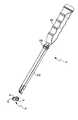
- FIG. 1is a perspective view of a laminar hook insertion device in accordance with an embodiment of the present disclosure
- FIG. 2is a perspective view of the laminar hook insertion device of FIG. 1 with a laminar hook removed from the insertion device;
- FIG. 3is a top view of the laminar hook insertion device of FIG. 2 ;
- FIG. 4is a side cross-sectional view of the laminar hook insertion device of FIG. 2 ;
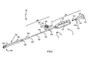
- FIG. 5is an exploded perspective view of the laminar hook insertion device of FIG. 2 with parts separated;
- FIG. 6is a side view of an elongate body assembly of the laminar hook insertion device of FIG. 2 ;
- FIG. 7is a longitudinal cross-sectional view of the elongate body assembly of FIG. 6 cut along a section line of 7 - 7 in FIG. 6 ;
- FIG. 8is a perspective view of the elongate body assembly of FIG. 6 illustrating a retaining portion thereof having support plates attached thereto;
- FIG. 9is a perspective view of the elongate body assembly of FIG. 8 illustrating the retaining portion with parts separated;
- FIG. 9Ais a perspective view of the area of detail indicated in FIG. 9 ;
- FIG. 10is a top view of the laminar hook insertion device of FIG. 1 having a laminar hook releasably attached thereto;
- FIG. 11is a side cross-sectional view of the laminar hook insertion device of FIG. 10 ;
- FIG. 12is a perspective view of the laminar hook insertion device of FIG. 1 illustrating detachment of the laminar hook;
- FIG. 13is a perspective view of the laminar hook for use with the laminar hook insertion device of FIG. 1 ;
- FIG. 14is a perspective view of the laminar hook of FIG. 13 engaged with a pedicle screw.
- FIG. 15is a perspective view of a vertebral body illustrating use of the laminar hook of FIG. 12 shown in phantom.
- distalwill refer to that portion of the instrument, apparatus, device or component thereof which is farther from the user while, the term “proximal,” will refer to that portion of the instrument, apparatus, device or component thereof which is closer to the user.
- proximalwill refer to that portion of the instrument, apparatus, device or component thereof which is closer to the user.
- cephaladis used in this application to indicate a direction toward a patient's head, while the term “caudad” indicates a direction toward the patient's feet.
- the term “medial”indicates a direction toward the middle of the body of the patient
- the term “lateral”indicates a direction toward a side of the body of the patient, i.e., away from the middle of the body of the patient.
- the term “posterior”indicates a direction toward the patient's back
- the term “anterior”indicates a direction toward the patient's front.
- a laminar hook insertion device 10defining a longitudinal axis “A-A.”
- Device 10is configured to operatively retain and release a laminar hook 50 utilized to provide coupling of a connecting rod 70 ( FIG. 15 ) to the spine by being anchored under the lamina.
- Device 10includes a handle assembly 100 , an elongate body assembly 200 extending distally from handle assembly 100 , a retaining portion 300 configured to releasably retain laminar hook 50 therein and an actuation assembly 500 operatively associated with laminar hook 50 for release of laminar hook 50 from an actuation rod 560 ( FIG. 4 ) of actuation assembly 500 .
- laminar hook 50is configured to provide coupling of a connecting rod 70 to the spine, wherein laminar hook 50 is inserted, for example, on the undersurface of the lamina which forms a shallow arch or an inverted ⁇ V shape.
- laminar hook 50includes a head portion 52 which may define a smooth bore opening 56 through which a bone screw 80 ( FIG. 14 ) is inserted into a bone and an arched portion 54 configured to engage, for example, the undersurface of the lamina.
- Arched portion 54conforms to the contour of a seating protrusion 280 ( FIG.
- arched portion 54defines a groove 55 on each lateral side thereof and a recess 58 configured and dimensioned to securely engage a distal end portion of an actuation rod 560 ( FIG. 5 ), as will be described hereinbelow.
- An example of a laminar hookis disclosed in commonly assigned U.S. patent application Ser. No. 12/812,829, filed on Aug. 18, 2010, the entire contents of which are fully incorporated herein by reference.
- bore 56may be threaded to engage threads on the bone screw or may have a lip disposed in the bore to engage threads on the screw to deform the lip and lock the screw to the hook.
- Such a structureis available from K2M, Inc. under the trademark tifix, substantially as described in U.S. Pat. No. 6,322,562 to Wolter.
- handle assembly 100includes a handle member 110 defining a channel 115 therethrough, an anchor member 120 , and a biasing member 130 disposed in channel 115 .
- anchor member 120includes a cap 122 and a stem 124 extending distally from cap 122 .
- Stem 124includes a neck portion 124 a disposed at a distal portion of stem 124 .
- Neck portion 124 ahas a diameter smaller than that of stem 124 .
- Neck portion 124 adefines a transverse bore 125 configured to be in alignment with a lateral bore 112 defined in handle member 110 .
- Stem 124is configured and dimensioned to be disposed within channel 115 of handle member 110 .
- Cap 122engages a proximal end portion of device 10 and seals a proximal end of channel 115 of handle member 110 .
- a pin 2is inserted through lateral bore 112 of handle member 110 and transverse bore 125 of anchor member 120 to secure anchor member 120 with handle member 110 .
- handle member 110 and anchor member 120may be detachably, e.g., threadably, coupled to each other to facilitate repair and maintenance of handle assembly 100 . It is further envisioned that handle member 110 may be monolithically formed with anchor member 120 .
- biasing member 130has a diameter comparable to or smaller than that of neck portion 124 a of anchor member 120 .
- one end of biasing member 130is positioned adjacent to a distal portion of neck portion 124 a of anchor member 120 . In this manner, biasing member 130 can be compressed against neck portion 124 a secured with handle member 110 , as will be described below.
- elongate body assembly 200includes an engaging member 240 and an outer body 220 extending distally from engaging member 240 .
- Engaging member 240is concentrically arranged with respect to outer body 220 .
- engaging member 240has a smaller outer diameter than that of outer body 220 , such that engaging member 240 is configured and dimensioned to be disposed within at least a portion of channel 115 of handle member 110 , and a proximal end portion of outer body 220 is adapted to be securely fixed to a distal end portion of handle member 110 to enclose a distal end of channel 115 .
- engaging member 240circumferentially surrounds neck portion 124 a of anchor member 120 and provides a friction fit feature against neck portion 124 a .
- biasing member 130is disposed in a proximal portion of engaging member 240 .
- Engaging member 240defines a bore 242 configured and dimensioned to receive pin 2 , whereby elongate body assembly 200 is securely coupled with handle assembly 100 .
- engaging portion 240 of elongate body assembly 200may be threadably connected with handle member 110 .
- outer body 220 and engaging member 240define a longitudinal lumen 230 of varying diameter, through which actuation rod 560 ( FIG. 4 ) of actuation assembly 500 is at least partially slideably disposed, as will be described in detail hereinbelow.
- lumen 230has a first portion 230 a and a second portion 230 b .
- First portion 230 a of lumen 230 ahas a larger diameter than that of second portion 230 b .
- the second portion 230 bextends from a distal end of outer body 220 to a point along outer body 220
- first portion 230 aextends from the point on outer body 220 to a proximal end of engaging member 240 configured to be disposed within a portion of channel 115 of handle member 110 .
- outer body 220defines a pair of opposing cavities 228 adjacent engaging member 240 configured to be disposed within a portion of handle member 110 .
- cavities 228are configured and dimensioned to receive a pair of pins 4 , 6 ( FIG. 5 ) coupling actuation rod 560 with actuator member 550 .
- Cavities 228are configured and dimensioned to enable longitudinal movement of pins 4 , 6 therein, as will be described hereinbelow.
- the distal end portion of outer body 220defines lateral recess portions 227 .
- Each lateral recess portion 227is configured and adapted to receive a support plate 320 ( FIG. 9 ).
- the distal end portion of outer body 220includes a seating protrusion 280 configured and adapted to accommodate at least a portion of laminar hook 50 , as will be discussed hereinbelow.
- Retaining portion 300is configured to releasably retain laminar hook 50 therein.
- Retaining portion 300includes a pair of support plates 320 disposed within respective lateral recess portions 227 .
- Each support plate 320defines a pair of bores 322 configured and dimensioned to receive pins 8 therethrough to securely engage support plate 320 with lateral recess portions 227 of outer body 220 .
- Outer body 220defines a pair of corresponding bores 288 .
- the pair of bores 288is arranged such that longitudinal movement of actuation rod 560 within lumen 230 is not affected by pins 8 therein.
- pins 8do not extend through lumen 230 , and thus pins 8 are used to secure both support plates 320 to respective lateral recess portions 227 .
- each support plate 320includes a substantially flat portion that is disposed in lateral recess portion 227 of outer body 220 .
- each support plate 320includes a retaining member 340 that generally conforms to the contour of seating protrusion 280 of outer body 220 .
- retaining member 340includes a contact surface 342 that engages a lateral surface of seating protrusion 280 .
- each retaining member 340defines a groove 360 ( FIG. 9A ) that is adapted to receive at least a portion of arched portion 54 of laminar hook 50 therein.
- retaining member 340includes a guide portion 361 ( FIG. 9A ) configured and dimensioned to engage groove 55 defined in each lateral side of arched portion 54 of laminar hook 50 .
- laminar hook insertion device 10further includes actuation assembly 500 operatively coupled with a laminar hook 50 ( FIG. 11 ) releasably disposed in retaining portion 300 .
- Actuation assembly 500includes an actuation rod 560 and an actuator member 550 .
- Actuation rod 560includes a first portion 524 and a second portion 522 extending distally from first portion 524 .
- First portion 524has a larger diameter than that of second portion 522 .
- the diameters of first and second portions 230 a , 230 b of lumen 230substantially correspond to those of first and second portions 524 , 522 of actuation rod 560 , respectively.
- actuation rod 560is slideably disposed in lumen 230 defined in outer body 220 and engaging member 240 of elongate body assembly 200 .
- a proximal end portion of actuation rod 560engages a distal end portion of biasing member 130 disposed within a proximal portion of first portion 230 a of lumen 230 .
- a distal end portion of actuation rod 560is adapted to securely and releasably engage a recess 58 ( FIG. 11 ) defined in laminar hook 50 disposed in retaining portion 300 , whereby distal end portion of actuation rod 560 protrudes slightly through a distal end of lumen 230 of elongate body assembly 200 .
- actuator member 550includes a base portion 552 and a pair of opposing guide members 554 extending from base member 552 .
- Actuator member 550defines a U-shaped cross-section defining a recess 530 .
- Actuator member 550is mounted on a portion of outer member 220 , and is operatively coupled with actuation rod 560 disposed in lumen 230 of elongate body assembly 200 .
- pins 4 , 6couple actuator member 550 with actuation rod 560 .
- pins 4 , 6are received through bores 506 defined in opposing guide members 554 and bores 590 defined in first portion 524 of actuation rod 560 through cavity 228 defined in outer body 220 .
- actuator member 550 mounted on at least a portion of outer body 220is slidable along cavity 228 of outer body 220 , which in turn imparts longitudinal movement to actuation rod 560 slideably disposed within lumen 230 defined in elongate body assembly 200 .
- actuation rod 560movement of actuation rod 560 is limited by biasing member 130 in the proximal direction and by second portion 230 b of lumen 230 which defines a smaller diameter than that of first portion of 524 of actuation rod 560 in the distal direction. Accordingly, when biasing member 130 is in a neutral state, i.e., unactuated state ( FIG. 11 ), biasing member 130 urges actuation rod 560 to the distal-most position within lumen 230 .
- a distal end portion of first portion 524 of actuation rod 560engages a proximal end portion of second portion 230 b of lumen 230 , whereby the smaller diameter of second portion 230 b of lumen 230 inhibits distal movement of first portion 524 of actuation rod 560 therethrough. More importantly, at this time, the distal end portion of second portion 522 of actuation rod 560 slightly extends out of the distal end of lumen 230 , whereby recess 58 of laminar hook 50 is securely engaged with a distal end portion of actuation rod 560 in retaining portion 300 .
- the distal and proximal limits of actuation rod 560is further defined by cavity 228 defined in outer member 220 of elongate body portion 200 , in which pins 4 , 6 slideably move therein.
- actuation rod 560protrudes slightly through the distal end of lumen 230 of outer member 220 and releasably engages recess 58 of laminar hook 50 .
- Arched portion 54 of hook 50conforms to the contour of seating protrusion 280 ( FIG. 9 ) of an outer body 220 to help securely retain laminar hook 50 in retaining portion 300 .
- pin 4 connected to actuator member 550is disposed in the distal-most position in cavity 228 defined in outer body 220 ( FIG. 12 ).
- actuation rod 560is also moved proximally as a single construct with actuator member 550 against the bias of biasing member 130 . Such movement disengages the distal end portion of actuation rod 560 from recess 58 of laminar hook 50 .
- the bias of biasing member 130urges actuation rod 560 to the distal-most position, which in turn positions pin 4 connected to actuator member 550 to the distal-most position in cavity 228 defined in outer body 220 .
- laminar hook 50Prior to the surgical procedure, laminar hook 50 is attached to retaining portion 300 of laminar hook insertion device 10 by sliding actuator member 550 in the proximal direction which in turn moves actuation rod 560 proximally to facilitate positioning of laminar hook 50 in retaining portion 300 .
- actuator member 560Upon positioning laminar hook 50 in retaining portion 300 , actuator member 560 is released to urge actuation rod 560 in the distal direction, whereby the distal portion of actuation rod 560 engages recess 58 defined in arched portion 54 of laminar hook 50 .
- the secure attachment of laminar hook 50 to laminar hook insertion device 10enables the surgeon to safely manipulate and deliver laminar hook 50 to the surgical site of interest.
- the surgeonaccesses the patient's spine in a known manner either using open surgical techniques or minimally invasive techniques, and prepares the bone to receive screws, as is deemed appropriate under the circumstances.
- the surgeoncan position arched portion 54 of laminar hook 50 to engage, for example, the undersurface of the lamina, and insert a bone screw into the bone through threaded bore 56 of laminar hook 50 .
- the bone screwmay be a pedicle screw 80 ( FIG. 14 ) including a shank 82 and a collet 84 .
- Pedicle screw 80may be of a rigid, unitary design or may be polyaxial. Examples of polyaxial screws are found in U.S. Pat. Nos.
- Collet 80is configured and dimensioned to receive a head of shank 82 such that collet 80 and the head are rotatable and pivotable in relation to each other, thereby allowing shank 82 to be repositioned in a plurality of orientations relative to collet 80 .
- the bone screwmay be a multi-planar taper lock screw (not shown) that enables manipulation of a screw shaft about multiple axes, whereby the bone screw is capable of securing connecting rod 70 with bone screws on multiple vertebral bodies that are aligned in the spinal column on different planes due to the curvature of the spine.
- the bone screwsmay be, for example, uniplanar screws and monoaxial taper lock screws.
- Multi-planar taper lock bone screwincludes a dual layered housing and screw shaft having a spherically configured screw head rotatably coupled with the housing.
- the dual layered housingincludes an outer housing and an inner housing.
- the outer housingcan be selectively positioned relative to the inner housing to fully lock the screw head and connecting rod 70 in position within the inner housing or alternatively to selectively partially lock the screw head and/or connecting rod 70 in position while permitting a sliding and/or rotating motion of connecting rod 70 and the screw head, respectively, relative to the bone screw.
- the outer housingis configured such that at least a portion of an inner surface of the outer housing is capable of sliding over a portion of an outer surface of the inner housing in upward and downward directions along the longitudinal axis of the bone screw.
- an inner surface of the outer housingcauses the inner housing to impart compressive force radially inward to secure connecting rod 70 at least partially disposed therein.
- One suitable taper lock screwis commercially available from K2M, Inc. (Leesburg, Va.) under the trade name MESATM.
- suitable multi-planar taper lock screwsare shown and described in U.S. Patent Application Publication 2008/0027432 and in U.S.
- Patent Application Publication 2007/0093817both of which are herein incorporated by reference in their entireties.
- a screw head having a rod receiving notchis disclosed in commonly assigned U.S. patent application Ser. Nos. 11/493,524 and 11/493,625, the complete disclosures of which are fully incorporated herein by reference.
- An example of a rod reduceris disclosed in commonly assigned U.S. Pat. No. 7,771,430, the entire contents of which are fully incorporated herein by reference.
- the surgeonreduces connecting rod 70 into the rod receiving notch of the screw head.
- the surgeonthen uses the locking instrument to lock or partially lock each screw to rod 70 .
- the surgeonmay partially lock each screw and before finishing the locking step may readjust the arrangement of the screws and rods 70 .
- the surgeoncan then fully lock each screw with the locking instrument.
- laminar hook 50may be utilized to extend around the pedicle “P” in the region of the inferior vertebral notch to provide enhanced stability and fixation of the pedicle screw, as shown in FIG. 15 . It is to be understood, therefore, that the disclosure is not limited to those precise embodiments, and that various other changes and modifications may be effected therein by one skilled in the art without departing from the scope or spirit of the disclosure.
Landscapes
- Health & Medical Sciences (AREA)
- Orthopedic Medicine & Surgery (AREA)
- Neurology (AREA)
- Life Sciences & Earth Sciences (AREA)
- Surgery (AREA)
- Heart & Thoracic Surgery (AREA)
- Engineering & Computer Science (AREA)
- Biomedical Technology (AREA)
- Nuclear Medicine, Radiotherapy & Molecular Imaging (AREA)
- Medical Informatics (AREA)
- Molecular Biology (AREA)
- Animal Behavior & Ethology (AREA)
- General Health & Medical Sciences (AREA)
- Public Health (AREA)
- Veterinary Medicine (AREA)
- Surgical Instruments (AREA)
Abstract
Description
Claims (23)
Priority Applications (2)
| Application Number | Priority Date | Filing Date | Title |
|---|---|---|---|
| US13/209,542US9247962B2 (en) | 2011-08-15 | 2011-08-15 | Laminar hook insertion device |
| US15/010,040US9498261B2 (en) | 2011-08-15 | 2016-01-29 | Laminar hook insertion device |
Applications Claiming Priority (1)
| Application Number | Priority Date | Filing Date | Title |
|---|---|---|---|
| US13/209,542US9247962B2 (en) | 2011-08-15 | 2011-08-15 | Laminar hook insertion device |
Related Child Applications (1)
| Application Number | Title | Priority Date | Filing Date |
|---|---|---|---|
| US15/010,040DivisionUS9498261B2 (en) | 2011-08-15 | 2016-01-29 | Laminar hook insertion device |
Publications (2)
| Publication Number | Publication Date |
|---|---|
| US20130046352A1 US20130046352A1 (en) | 2013-02-21 |
| US9247962B2true US9247962B2 (en) | 2016-02-02 |
Family
ID=47713189
Family Applications (2)
| Application Number | Title | Priority Date | Filing Date |
|---|---|---|---|
| US13/209,542Active2032-05-16US9247962B2 (en) | 2011-08-15 | 2011-08-15 | Laminar hook insertion device |
| US15/010,040Expired - Fee RelatedUS9498261B2 (en) | 2011-08-15 | 2016-01-29 | Laminar hook insertion device |
Family Applications After (1)
| Application Number | Title | Priority Date | Filing Date |
|---|---|---|---|
| US15/010,040Expired - Fee RelatedUS9498261B2 (en) | 2011-08-15 | 2016-01-29 | Laminar hook insertion device |
Country Status (1)
| Country | Link |
|---|---|
| US (2) | US9247962B2 (en) |
Cited By (1)
| Publication number | Priority date | Publication date | Assignee | Title |
|---|---|---|---|---|
| US20170065306A1 (en)* | 2004-02-17 | 2017-03-09 | Globus Medical, Inc. | Facet joint replacement instruments and methods |
Families Citing this family (16)
| Publication number | Priority date | Publication date | Assignee | Title |
|---|---|---|---|---|
| US8790380B2 (en)* | 2007-07-26 | 2014-07-29 | Dynamic Spine, Llc | Segmental orthopaedic device for spinal elongation and for treatment of scoliosis |
| US9204908B2 (en) | 2007-07-26 | 2015-12-08 | Dynamic Spine, Llc | Segmental orthopedic device for spinal elongation and for treatment of scoliosis |
| AU2011264818B2 (en) | 2010-06-10 | 2015-06-18 | Globus Medical, Inc. | Low-profile, uniplanar bone screw |
| JP6290002B2 (en)* | 2013-06-07 | 2018-03-07 | 賢 石井 | Spinal fixation device |
| US20170105768A1 (en)* | 2015-10-19 | 2017-04-20 | Alphatec Spine, Inc. | Hook inserter |
| US9962192B2 (en) | 2016-03-17 | 2018-05-08 | Medos International Sarl | Multipoint fixation implants |
| US10966762B2 (en) | 2017-12-15 | 2021-04-06 | Medos International Sarl | Unilateral implant holders and related methods |
| US10898232B2 (en) | 2018-03-20 | 2021-01-26 | Medos International Sàrl | Multipoint fixation implants and related methods |
| CN109528254A (en)* | 2018-10-24 | 2019-03-29 | 郭心舟 | A kind of laminectomy retractor |
| US11291482B2 (en) | 2019-03-21 | 2022-04-05 | Medos International Sarl | Rod reducers and related methods |
| USD1004774S1 (en) | 2019-03-21 | 2023-11-14 | Medos International Sarl | Kerrison rod reducer |
| US11291481B2 (en) | 2019-03-21 | 2022-04-05 | Medos International Sarl | Rod reducers and related methods |
| US11426210B2 (en) | 2019-09-25 | 2022-08-30 | Medos International Sàrl | Multipoint angled fixation implants for multiple screws and related methods |
| EP4103083B1 (en) | 2020-02-14 | 2024-10-23 | Medos International Sàrl | Integrated multipoint fixation screw |
| EP4240262B1 (en) | 2020-11-09 | 2024-12-04 | Medos International Sàrl | Biplanar forceps reducers |
| US12431114B2 (en) | 2023-04-07 | 2025-09-30 | Google Llc | Delay estimation for performing echo cancellation for co-located devices |
Citations (80)
| Publication number | Priority date | Publication date | Assignee | Title |
|---|---|---|---|---|
| US5005562A (en) | 1988-06-24 | 1991-04-09 | Societe De Fabrication De Material Orthopedique | Implant for spinal osteosynthesis device, in particular in traumatology |
| US5257993A (en) | 1991-10-04 | 1993-11-02 | Acromed Corporation | Top-entry rod retainer |
| US5263954A (en) | 1991-06-05 | 1993-11-23 | Synthes (U.S.A.) | Pedicle hook |
| US5368594A (en) | 1991-09-30 | 1994-11-29 | Fixano S.A. | Vertebral osteosynthesis device |
| US5374267A (en) | 1992-02-17 | 1994-12-20 | Acromed B.V. | Device for fixing at least a part of the human cervical and/or thoracic vertebral column |
| US5397363A (en) | 1992-08-11 | 1995-03-14 | Gelbard; Steven D. | Spinal stabilization implant system |
| US5415659A (en) | 1993-12-01 | 1995-05-16 | Amei Technologies Inc. | Spinal fixation system and pedicle clamp |
| US5437669A (en) | 1993-08-12 | 1995-08-01 | Amei Technologies Inc. | Spinal fixation systems with bifurcated connectors |
| US5476464A (en) | 1993-02-25 | 1995-12-19 | Howmedica Gmbh | Device for setting a spine |
| US5527314A (en) | 1993-01-04 | 1996-06-18 | Danek Medical, Inc. | Spinal fixation system |
| US5542946A (en) | 1994-05-27 | 1996-08-06 | Sofamor S.N.C. | Hook for an occipito-cervical rod or plate of an occipito-cervical osteosynthesis instrumentation |
| US5575792A (en) | 1995-07-14 | 1996-11-19 | Fastenetix, L.L.C. | Extending hook and polyaxial coupling element device for use with top loading rod fixation devices |
| US5578033A (en) | 1995-07-13 | 1996-11-26 | Fastenetix, L.L.C. | Advanced polyaxial locking hook and coupling element device for use with side loading rod fixation devices |
| US5584832A (en) | 1993-03-15 | 1996-12-17 | Synthes (U.S.A.) | Hook with screw for treatment of vertebral column deformities |
| US5609594A (en) | 1995-07-13 | 1997-03-11 | Fastenetix Llc | Extending hook and polyaxial coupling element device for use with side loading road fixation devices |
| US5609593A (en) | 1995-07-13 | 1997-03-11 | Fastenetix, Llc | Advanced polyaxial locking hook and coupling element device for use with top loading rod fixation devices |
| US5620444A (en) | 1993-09-03 | 1997-04-15 | Sofamor S.N.C. | Clamp for stabilizing a cervical spine segment |
| US5630816A (en) | 1995-05-01 | 1997-05-20 | Kambin; Parviz | Double barrel spinal fixation system and method |
| US5630817A (en) | 1992-11-18 | 1997-05-20 | Eurosurgical | Rod attachment device for rachidian orthopaedy |
| US5676665A (en) | 1995-06-23 | 1997-10-14 | Bryan; Donald W. | Spinal fixation apparatus and method |
| US5688274A (en) | 1995-10-23 | 1997-11-18 | Fastenetix Llc. | Spinal implant device having a single central rod and claw hooks |
| US5688273A (en) | 1995-10-23 | 1997-11-18 | Fastenetix, Llc. | Spinal implant apparatus having a single central rod and plow hooks |
| US5725527A (en) | 1992-09-10 | 1998-03-10 | Biedermann Motech Gmbh | Anchoring member |
| US5733285A (en) | 1995-07-13 | 1998-03-31 | Fastenetix, Llc | Polyaxial locking mechanism |
| US5741254A (en) | 1993-04-19 | 1998-04-21 | Stryker Corporation | Implant for an ostheosynthesis device, in particular for the spine |
| US5752957A (en) | 1997-02-12 | 1998-05-19 | Third Millennium Engineering, Llc | Polyaxial mechanism for use with orthopaedic implant devices |
| US5810818A (en) | 1995-10-23 | 1998-09-22 | Fastenetix, Llc | Spinal hook implant having a low blade and S swivel hook |
| US5810817A (en) | 1992-06-19 | 1998-09-22 | Roussouly; Pierre | Spinal therapy apparatus |
| US5810816A (en) | 1994-04-20 | 1998-09-22 | Roussouly; Pierre | Device for stabilizing orthopedic anchors |
| US5888221A (en) | 1992-08-11 | 1999-03-30 | Gelbard; Steven D. | Spinal stabilization implant system |
| US5928232A (en) | 1994-11-16 | 1999-07-27 | Advanced Spine Fixation Systems, Incorporated | Spinal fixation system |
| US5989250A (en) | 1996-10-24 | 1999-11-23 | Spinal Concepts, Inc. | Method and apparatus for spinal fixation |
| US6010503A (en) | 1998-04-03 | 2000-01-04 | Spinal Innovations, Llc | Locking mechanism |
| US6077263A (en) | 1997-08-13 | 2000-06-20 | Aesculap Ag & Co. Kg | Vertebral osteosynthetic system |
| US6086588A (en) | 1997-05-07 | 2000-07-11 | Aesculap Ag & Co. Kg | Osteosynthesis system for vertebra arthrodesis |
| US6132430A (en) | 1996-10-24 | 2000-10-17 | Spinal Concepts, Inc. | Spinal fixation system |
| US6322562B1 (en) | 1998-12-19 | 2001-11-27 | Dietmar Wolter | Fixation system for bones |
| US6352537B1 (en) | 1998-09-17 | 2002-03-05 | Electro-Biology, Inc. | Method and apparatus for spinal fixation |
| US6475218B2 (en) | 2000-06-30 | 2002-11-05 | Sofamor, S.N.C. | Spinal implant for an osteosynthesis device |
| US6485491B1 (en) | 2000-09-15 | 2002-11-26 | Sdgi Holdings, Inc. | Posterior fixation system |
| US6554831B1 (en) | 2000-09-01 | 2003-04-29 | Hopital Sainte-Justine | Mobile dynamic system for treating spinal disorder |
| US6565565B1 (en) | 1998-06-17 | 2003-05-20 | Howmedica Osteonics Corp. | Device for securing spinal rods |
| US6589243B1 (en) | 1998-09-18 | 2003-07-08 | Guy Viart | Posterior backbone osteosynthesis device |
| US6626908B2 (en) | 2000-07-22 | 2003-09-30 | Corin Spinal Systems Limited | Pedicle attachment assembly |
| US6641585B2 (en) | 2000-09-22 | 2003-11-04 | Showa Ika Kohgyo Co., Ltd. | Bone connecting tool and connecting member thereof |
| US6656180B2 (en) | 2001-09-05 | 2003-12-02 | Stahurski Consulting Inc. | Apparatus for retaining vertebrae in a desired spatial relationship |
| US6740089B2 (en) | 2002-01-10 | 2004-05-25 | Thomas T. Haider | Orthopedic hook system |
| US6746449B2 (en) | 2001-09-12 | 2004-06-08 | Spinal Concepts, Inc. | Spinal rod translation instrument |
| US20040111091A1 (en)* | 2002-05-21 | 2004-06-10 | James Ogilvie | Reduction cable and bone anchor |
| US6749361B2 (en) | 1997-10-06 | 2004-06-15 | Werner Hermann | Shackle element for clamping a fixation rod, a method for making a shackle element, a hook with a shackle element and a rode connector with a shackle element |
| US20040147937A1 (en)* | 2003-01-24 | 2004-07-29 | Depuy Spine, Inc. | Spinal rod approximators |
| US6805716B2 (en)* | 2001-07-16 | 2004-10-19 | Spine Core, Inc. | Orthopedic device set for reorienting vertebral bones for the treatment of scoliosis |
| US20050113927A1 (en)* | 2003-11-25 | 2005-05-26 | Malek Michel H. | Spinal stabilization systems |
| US20050137593A1 (en)* | 2000-10-02 | 2005-06-23 | Sulzer Spine-Tech Inc. | Temporary spinal fixation apparatuses and methods |
| US6911030B1 (en) | 1999-07-01 | 2005-06-28 | Spinevision S.A. | Fixing element and ancillary for stabilizing vertebrae |
| US6945972B2 (en) | 2000-08-24 | 2005-09-20 | Synthes | Apparatus for connecting a bone fastener to a longitudinal rod |
| USRE39035E1 (en) | 1994-11-18 | 2006-03-21 | Howmedica Osteonics Corp. | Universal coupler for spinal fixation |
| US20060084990A1 (en) | 2004-05-26 | 2006-04-20 | Jose Gournay | Dual anchor spinal implant apparatus |
| US20060200132A1 (en)* | 2005-03-04 | 2006-09-07 | Chao Nam T | Instruments and methods for manipulating a vertebra |
| US20060235426A1 (en)* | 2005-04-15 | 2006-10-19 | Sdgi Holdings, Inc. | Instruments, implants and methods for positioning implants into a spinal disc space |
| US7160300B2 (en) | 2004-02-27 | 2007-01-09 | Jackson Roger P | Orthopedic implant rod reduction tool set and method |
| US20070016189A1 (en) | 2005-06-30 | 2007-01-18 | Depuy Spine Sarl | Orthopedic clamping hook assembly |
| US20070049931A1 (en)* | 2005-08-26 | 2007-03-01 | Sdgi Holdings, Inc. | Instruments for minimally invasive stabilization of bony structures |
| US20070282337A1 (en)* | 2006-05-18 | 2007-12-06 | Laszlo Garamszegi | Rod reducer |
| US7322979B2 (en) | 2000-03-15 | 2008-01-29 | Warsaw Orthopedic, Inc. | Multidirectional pivoting bone screw and fixation system |
| US20080306488A1 (en)* | 2007-06-07 | 2008-12-11 | Moti Altarac | Inserter for a spinal implant |
| US7485133B2 (en) | 2004-07-14 | 2009-02-03 | Warsaw Orthopedic, Inc. | Force diffusion spinal hook |
| WO2009091689A1 (en) | 2008-01-14 | 2009-07-23 | K2M, Inc. | Spinal fixation device and method |
| US20090234395A1 (en)* | 2006-08-16 | 2009-09-17 | Hoffman Jeffrey A | Insertion Instrument for a Spinal Fixation System |
| US20090318970A1 (en) | 2008-06-19 | 2009-12-24 | Butler Michael S | Spinal Rod Connectors Configured to Retain Spinal Rods of Varying Diameters |
| US7651516B2 (en) | 2000-12-01 | 2010-01-26 | Spinevision S.A. | Connection assembly for the field of spinal osteosynthesis and method for using at least one such assembly |
| US7674277B2 (en) | 2004-12-01 | 2010-03-09 | Warsaw Orthopedic, Inc. | Side-loading bone anchor |
| US7785352B2 (en) | 2006-07-13 | 2010-08-31 | Mass Modular Spine Group, Inc. | Modular spinal fixation system |
| US20100222822A1 (en) | 2002-08-28 | 2010-09-02 | Warsaw Orthopedic, Inc. | Posterior Fixation System |
| US7789899B2 (en) | 2004-12-30 | 2010-09-07 | Warsaw Orthopedic, Inc. | Bone anchorage screw with built-in hinged plate |
| US20100274291A1 (en) | 2009-04-23 | 2010-10-28 | Custom Spine, Inc. | Spinal Fixation Mechanism |
| US7935133B2 (en) | 2008-02-08 | 2011-05-03 | Mmsn Limited Partnership | Interlaminar hook |
| US7988694B2 (en)* | 2005-09-29 | 2011-08-02 | K2M, Inc. | Spinal fixation system having locking and unlocking devices for use with a multi-planar, taper lock screw |
| US8202299B2 (en)* | 2008-03-19 | 2012-06-19 | Collabcom II, LLC | Interspinous implant, tools and methods of implanting |
| US8343163B1 (en)* | 2008-02-14 | 2013-01-01 | Nuvasive, Inc. | Spinal implant installation device |
Family Cites Families (5)
| Publication number | Priority date | Publication date | Assignee | Title |
|---|---|---|---|---|
| US4409968A (en)* | 1980-02-04 | 1983-10-18 | Drummond Denis S | Method and apparatus for engaging a hook assembly to a spinal column |
| US5102412A (en)* | 1990-06-19 | 1992-04-07 | Chaim Rogozinski | System for instrumentation of the spine in the treatment of spinal deformities |
| WO2003007829A1 (en)* | 2001-07-20 | 2003-01-30 | Spinal Concepts, Inc. | Spinal stabilization system and method |
| US8226690B2 (en)* | 2005-07-22 | 2012-07-24 | The Board Of Trustees Of The Leland Stanford Junior University | Systems and methods for stabilization of bone structures |
| AR064013A1 (en)* | 2006-11-30 | 2009-03-04 | Paradigm Spine Llc | VERTEBRAL, INTERLAMINAR, INTERESPINOUS STABILIZATION SYSTEM |
- 2011
- 2011-08-15USUS13/209,542patent/US9247962B2/enactiveActive
- 2016
- 2016-01-29USUS15/010,040patent/US9498261B2/ennot_activeExpired - Fee Related
Patent Citations (93)
| Publication number | Priority date | Publication date | Assignee | Title |
|---|---|---|---|---|
| US5005562A (en) | 1988-06-24 | 1991-04-09 | Societe De Fabrication De Material Orthopedique | Implant for spinal osteosynthesis device, in particular in traumatology |
| US5263954A (en) | 1991-06-05 | 1993-11-23 | Synthes (U.S.A.) | Pedicle hook |
| US5368594A (en) | 1991-09-30 | 1994-11-29 | Fixano S.A. | Vertebral osteosynthesis device |
| US5257993A (en) | 1991-10-04 | 1993-11-02 | Acromed Corporation | Top-entry rod retainer |
| US5346493A (en) | 1991-10-04 | 1994-09-13 | Acromed Corporation | Top-entry rod retainer |
| US5374267A (en) | 1992-02-17 | 1994-12-20 | Acromed B.V. | Device for fixing at least a part of the human cervical and/or thoracic vertebral column |
| US5810817A (en) | 1992-06-19 | 1998-09-22 | Roussouly; Pierre | Spinal therapy apparatus |
| US5397363A (en) | 1992-08-11 | 1995-03-14 | Gelbard; Steven D. | Spinal stabilization implant system |
| US5888221A (en) | 1992-08-11 | 1999-03-30 | Gelbard; Steven D. | Spinal stabilization implant system |
| US5725527A (en) | 1992-09-10 | 1998-03-10 | Biedermann Motech Gmbh | Anchoring member |
| US5630817A (en) | 1992-11-18 | 1997-05-20 | Eurosurgical | Rod attachment device for rachidian orthopaedy |
| US5527314A (en) | 1993-01-04 | 1996-06-18 | Danek Medical, Inc. | Spinal fixation system |
| US5609592A (en) | 1993-01-04 | 1997-03-11 | Danek Medical, Inc. | Spinal Fixation System |
| US5476464A (en) | 1993-02-25 | 1995-12-19 | Howmedica Gmbh | Device for setting a spine |
| US5584832A (en) | 1993-03-15 | 1996-12-17 | Synthes (U.S.A.) | Hook with screw for treatment of vertebral column deformities |
| US5741254A (en) | 1993-04-19 | 1998-04-21 | Stryker Corporation | Implant for an ostheosynthesis device, in particular for the spine |
| US5437669A (en) | 1993-08-12 | 1995-08-01 | Amei Technologies Inc. | Spinal fixation systems with bifurcated connectors |
| US5620444A (en) | 1993-09-03 | 1997-04-15 | Sofamor S.N.C. | Clamp for stabilizing a cervical spine segment |
| US5415659A (en) | 1993-12-01 | 1995-05-16 | Amei Technologies Inc. | Spinal fixation system and pedicle clamp |
| US5810816A (en) | 1994-04-20 | 1998-09-22 | Roussouly; Pierre | Device for stabilizing orthopedic anchors |
| US5542946A (en) | 1994-05-27 | 1996-08-06 | Sofamor S.N.C. | Hook for an occipito-cervical rod or plate of an occipito-cervical osteosynthesis instrumentation |
| US5928232A (en) | 1994-11-16 | 1999-07-27 | Advanced Spine Fixation Systems, Incorporated | Spinal fixation system |
| USRE39035E1 (en) | 1994-11-18 | 2006-03-21 | Howmedica Osteonics Corp. | Universal coupler for spinal fixation |
| US5630816A (en) | 1995-05-01 | 1997-05-20 | Kambin; Parviz | Double barrel spinal fixation system and method |
| US5676665A (en) | 1995-06-23 | 1997-10-14 | Bryan; Donald W. | Spinal fixation apparatus and method |
| US5609593A (en) | 1995-07-13 | 1997-03-11 | Fastenetix, Llc | Advanced polyaxial locking hook and coupling element device for use with top loading rod fixation devices |
| US5609594A (en) | 1995-07-13 | 1997-03-11 | Fastenetix Llc | Extending hook and polyaxial coupling element device for use with side loading road fixation devices |
| US5578033A (en) | 1995-07-13 | 1996-11-26 | Fastenetix, L.L.C. | Advanced polyaxial locking hook and coupling element device for use with side loading rod fixation devices |
| US5733285A (en) | 1995-07-13 | 1998-03-31 | Fastenetix, Llc | Polyaxial locking mechanism |
| US5575792A (en) | 1995-07-14 | 1996-11-19 | Fastenetix, L.L.C. | Extending hook and polyaxial coupling element device for use with top loading rod fixation devices |
| US5688274A (en) | 1995-10-23 | 1997-11-18 | Fastenetix Llc. | Spinal implant device having a single central rod and claw hooks |
| US5688273A (en) | 1995-10-23 | 1997-11-18 | Fastenetix, Llc. | Spinal implant apparatus having a single central rod and plow hooks |
| US5810818A (en) | 1995-10-23 | 1998-09-22 | Fastenetix, Llc | Spinal hook implant having a low blade and S swivel hook |
| US6416515B1 (en) | 1996-10-24 | 2002-07-09 | Spinal Concepts, Inc. | Spinal fixation system |
| US6132430A (en) | 1996-10-24 | 2000-10-17 | Spinal Concepts, Inc. | Spinal fixation system |
| US5989250A (en) | 1996-10-24 | 1999-11-23 | Spinal Concepts, Inc. | Method and apparatus for spinal fixation |
| US6613050B1 (en) | 1996-10-24 | 2003-09-02 | Spinal Concepts, Inc. | Method and apparatus for spinal fixation |
| US6595992B1 (en) | 1996-10-24 | 2003-07-22 | Spinal Concepts, Inc. | Method and apparatus for spinal fixation |
| US6562040B1 (en) | 1996-10-24 | 2003-05-13 | Spinal Concepts, Inc. | Spinal fixation system |
| US5752957A (en) | 1997-02-12 | 1998-05-19 | Third Millennium Engineering, Llc | Polyaxial mechanism for use with orthopaedic implant devices |
| US6086588A (en) | 1997-05-07 | 2000-07-11 | Aesculap Ag & Co. Kg | Osteosynthesis system for vertebra arthrodesis |
| US6077263A (en) | 1997-08-13 | 2000-06-20 | Aesculap Ag & Co. Kg | Vertebral osteosynthetic system |
| US6749361B2 (en) | 1997-10-06 | 2004-06-15 | Werner Hermann | Shackle element for clamping a fixation rod, a method for making a shackle element, a hook with a shackle element and a rode connector with a shackle element |
| US6010503A (en) | 1998-04-03 | 2000-01-04 | Spinal Innovations, Llc | Locking mechanism |
| US6565565B1 (en) | 1998-06-17 | 2003-05-20 | Howmedica Osteonics Corp. | Device for securing spinal rods |
| US7819901B2 (en) | 1998-06-17 | 2010-10-26 | Howmedica Osteonics Corp. | Device for securing spinal rods |
| US7780703B2 (en) | 1998-06-17 | 2010-08-24 | Howmedica Osteonics Corp. | Device for securing spinal rods |
| US7608095B2 (en) | 1998-06-17 | 2009-10-27 | Howmedica Osteonics Corp. | Device for securing spinal rods |
| US6352537B1 (en) | 1998-09-17 | 2002-03-05 | Electro-Biology, Inc. | Method and apparatus for spinal fixation |
| US6589243B1 (en) | 1998-09-18 | 2003-07-08 | Guy Viart | Posterior backbone osteosynthesis device |
| US6322562B1 (en) | 1998-12-19 | 2001-11-27 | Dietmar Wolter | Fixation system for bones |
| US6911030B1 (en) | 1999-07-01 | 2005-06-28 | Spinevision S.A. | Fixing element and ancillary for stabilizing vertebrae |
| US7322979B2 (en) | 2000-03-15 | 2008-01-29 | Warsaw Orthopedic, Inc. | Multidirectional pivoting bone screw and fixation system |
| US6475218B2 (en) | 2000-06-30 | 2002-11-05 | Sofamor, S.N.C. | Spinal implant for an osteosynthesis device |
| US6626908B2 (en) | 2000-07-22 | 2003-09-30 | Corin Spinal Systems Limited | Pedicle attachment assembly |
| US6945972B2 (en) | 2000-08-24 | 2005-09-20 | Synthes | Apparatus for connecting a bone fastener to a longitudinal rod |
| US6554831B1 (en) | 2000-09-01 | 2003-04-29 | Hopital Sainte-Justine | Mobile dynamic system for treating spinal disorder |
| US6485491B1 (en) | 2000-09-15 | 2002-11-26 | Sdgi Holdings, Inc. | Posterior fixation system |
| US6641585B2 (en) | 2000-09-22 | 2003-11-04 | Showa Ika Kohgyo Co., Ltd. | Bone connecting tool and connecting member thereof |
| US20050137593A1 (en)* | 2000-10-02 | 2005-06-23 | Sulzer Spine-Tech Inc. | Temporary spinal fixation apparatuses and methods |
| US7651516B2 (en) | 2000-12-01 | 2010-01-26 | Spinevision S.A. | Connection assembly for the field of spinal osteosynthesis and method for using at least one such assembly |
| US6805716B2 (en)* | 2001-07-16 | 2004-10-19 | Spine Core, Inc. | Orthopedic device set for reorienting vertebral bones for the treatment of scoliosis |
| US6656180B2 (en) | 2001-09-05 | 2003-12-02 | Stahurski Consulting Inc. | Apparatus for retaining vertebrae in a desired spatial relationship |
| US6746449B2 (en) | 2001-09-12 | 2004-06-08 | Spinal Concepts, Inc. | Spinal rod translation instrument |
| US6740089B2 (en) | 2002-01-10 | 2004-05-25 | Thomas T. Haider | Orthopedic hook system |
| US7338490B2 (en) | 2002-05-21 | 2008-03-04 | Warsaw Orthopedic, Inc. | Reduction cable and bone anchor |
| US20040111091A1 (en)* | 2002-05-21 | 2004-06-10 | James Ogilvie | Reduction cable and bone anchor |
| US20100222822A1 (en) | 2002-08-28 | 2010-09-02 | Warsaw Orthopedic, Inc. | Posterior Fixation System |
| US20040147937A1 (en)* | 2003-01-24 | 2004-07-29 | Depuy Spine, Inc. | Spinal rod approximators |
| US20050113927A1 (en)* | 2003-11-25 | 2005-05-26 | Malek Michel H. | Spinal stabilization systems |
| US7160300B2 (en) | 2004-02-27 | 2007-01-09 | Jackson Roger P | Orthopedic implant rod reduction tool set and method |
| US20060084990A1 (en) | 2004-05-26 | 2006-04-20 | Jose Gournay | Dual anchor spinal implant apparatus |
| US7485133B2 (en) | 2004-07-14 | 2009-02-03 | Warsaw Orthopedic, Inc. | Force diffusion spinal hook |
| US7674277B2 (en) | 2004-12-01 | 2010-03-09 | Warsaw Orthopedic, Inc. | Side-loading bone anchor |
| US7789899B2 (en) | 2004-12-30 | 2010-09-07 | Warsaw Orthopedic, Inc. | Bone anchorage screw with built-in hinged plate |
| US20070162010A1 (en)* | 2005-03-04 | 2007-07-12 | Chao Nam T | Instruments and methods for manipulating vertebra |
| US20060200132A1 (en)* | 2005-03-04 | 2006-09-07 | Chao Nam T | Instruments and methods for manipulating a vertebra |
| US20060235426A1 (en)* | 2005-04-15 | 2006-10-19 | Sdgi Holdings, Inc. | Instruments, implants and methods for positioning implants into a spinal disc space |
| US20070016189A1 (en) | 2005-06-30 | 2007-01-18 | Depuy Spine Sarl | Orthopedic clamping hook assembly |
| US20070049931A1 (en)* | 2005-08-26 | 2007-03-01 | Sdgi Holdings, Inc. | Instruments for minimally invasive stabilization of bony structures |
| US7988694B2 (en)* | 2005-09-29 | 2011-08-02 | K2M, Inc. | Spinal fixation system having locking and unlocking devices for use with a multi-planar, taper lock screw |
| US20070282337A1 (en)* | 2006-05-18 | 2007-12-06 | Laszlo Garamszegi | Rod reducer |
| US7785352B2 (en) | 2006-07-13 | 2010-08-31 | Mass Modular Spine Group, Inc. | Modular spinal fixation system |
| US20090234395A1 (en)* | 2006-08-16 | 2009-09-17 | Hoffman Jeffrey A | Insertion Instrument for a Spinal Fixation System |
| US20080306488A1 (en)* | 2007-06-07 | 2008-12-11 | Moti Altarac | Inserter for a spinal implant |
| US8114092B2 (en)* | 2007-06-07 | 2012-02-14 | Exactech, Inc. | Inserter for a spinal implant |
| US20100305616A1 (en)* | 2008-01-14 | 2010-12-02 | John Carbone | Spinal fixation device and method |
| WO2009091689A1 (en) | 2008-01-14 | 2009-07-23 | K2M, Inc. | Spinal fixation device and method |
| US7935133B2 (en) | 2008-02-08 | 2011-05-03 | Mmsn Limited Partnership | Interlaminar hook |
| US8343163B1 (en)* | 2008-02-14 | 2013-01-01 | Nuvasive, Inc. | Spinal implant installation device |
| US8202299B2 (en)* | 2008-03-19 | 2012-06-19 | Collabcom II, LLC | Interspinous implant, tools and methods of implanting |
| US20090318970A1 (en) | 2008-06-19 | 2009-12-24 | Butler Michael S | Spinal Rod Connectors Configured to Retain Spinal Rods of Varying Diameters |
| US20100274291A1 (en) | 2009-04-23 | 2010-10-28 | Custom Spine, Inc. | Spinal Fixation Mechanism |
Cited By (1)
| Publication number | Priority date | Publication date | Assignee | Title |
|---|---|---|---|---|
| US20170065306A1 (en)* | 2004-02-17 | 2017-03-09 | Globus Medical, Inc. | Facet joint replacement instruments and methods |
Also Published As
| Publication number | Publication date |
|---|---|
| US9498261B2 (en) | 2016-11-22 |
| US20160143673A1 (en) | 2016-05-26 |
| US20130046352A1 (en) | 2013-02-21 |
Similar Documents
| Publication | Publication Date | Title |
|---|---|---|
| US9498261B2 (en) | Laminar hook insertion device | |
| US9820779B2 (en) | Spinal stabilization system | |
| US9452000B2 (en) | Rod reducer | |
| US11241258B2 (en) | Bone screw | |
| US9271763B2 (en) | Transverse rod connector | |
| CN103717159B (en) | Minimally Invasive Spinal Fixation System Including Vertebral Alignment Features | |
| US8747409B2 (en) | Surgical instrument for positioning a spinal rod | |
| EP2667807B1 (en) | Instruments for adjusting relative positioning of bones or bony tissues | |
| US20150100098A1 (en) | Rod reducer | |
| EP2730242B1 (en) | Spine stabilization system | |
| US20050059969A1 (en) | Rod approximator | |
| US20050085813A1 (en) | System and method for stabilizing of internal structures | |
| EP3288473B1 (en) | Rod reducer | |
| EP2881054B1 (en) | Spinal stabilization system including shaped spinal rod | |
| US9744050B1 (en) | Compression and distraction system for percutaneous posterior spinal fusion | |
| US20220160402A1 (en) | Bone screw | |
| US11109894B2 (en) | Apparatus, system, and method for spinal vertebrae stabilization | |
| AU2015203073B2 (en) | Spinal stabilization system |
Legal Events
| Date | Code | Title | Description |
|---|---|---|---|
| AS | Assignment | Owner name:K2M, INC., VIRGINIA Free format text:ASSIGNMENT OF ASSIGNORS INTEREST;ASSIGNOR:MCCLINTOCK, LARRY;REEL/FRAME:026748/0283 Effective date:20110812 | |
| AS | Assignment | Owner name:SILICON VALLEY BANK, MASSACHUSETTS Free format text:SECURITY INTEREST;ASSIGNORS:K2M, INC.;K2M HOLDING, INC.;K2M UK LIMITED;REEL/FRAME:029489/0327 Effective date:20121029 | |
| AS | Assignment | Owner name:SILICON VALLEY BANK, CALIFORNIA Free format text:FIRST AMENDMENT TO PATENT SECURITY AGREEMENT;ASSIGNORS:K2M, INC.;K2M UNLIMITED;K2M HOLDINGS, INC.;REEL/FRAME:034034/0097 Effective date:20141021 | |
| STCF | Information on status: patent grant | Free format text:PATENTED CASE | |
| AS | Assignment | Owner name:SILICON VALLEY BANK, AS ADMINISTRATIVE AGENT, CALIFORNIA Free format text:THIRD AMENDMENT TO PATENT SECURITY AGREEMENT;ASSIGNORS:K2M, INC.;K2M HOLDINGS, INC.;K2M UK LIMITED;REEL/FRAME:039627/0659 Effective date:20160808 Owner name:SILICON VALLEY BANK, AS ADMINISTRATIVE AGENT, CALI Free format text:THIRD AMENDMENT TO PATENT SECURITY AGREEMENT;ASSIGNORS:K2M, INC.;K2M HOLDINGS, INC.;K2M UK LIMITED;REEL/FRAME:039627/0659 Effective date:20160808 | |
| AS | Assignment | Owner name:K2M HOLDINGS, INC., VIRGINIA Free format text:RELEASE BY SECURED PARTY;ASSIGNOR:SILICON VALLEY BANK;REEL/FRAME:047496/0001 Effective date:20181109 Owner name:K2M, INC., VIRGINIA Free format text:RELEASE BY SECURED PARTY;ASSIGNOR:SILICON VALLEY BANK;REEL/FRAME:047496/0001 Effective date:20181109 Owner name:K2M UK LIMITED, UNITED KINGDOM Free format text:RELEASE BY SECURED PARTY;ASSIGNOR:SILICON VALLEY BANK;REEL/FRAME:047496/0001 Effective date:20181109 | |
| FEPP | Fee payment procedure | Free format text:ENTITY STATUS SET TO UNDISCOUNTED (ORIGINAL EVENT CODE: BIG.); ENTITY STATUS OF PATENT OWNER: LARGE ENTITY | |
| MAFP | Maintenance fee payment | Free format text:PAYMENT OF MAINTENANCE FEE, 4TH YEAR, LARGE ENTITY (ORIGINAL EVENT CODE: M1551); ENTITY STATUS OF PATENT OWNER: LARGE ENTITY Year of fee payment:4 | |
| MAFP | Maintenance fee payment | Free format text:PAYMENT OF MAINTENANCE FEE, 8TH YEAR, LARGE ENTITY (ORIGINAL EVENT CODE: M1552); ENTITY STATUS OF PATENT OWNER: LARGE ENTITY Year of fee payment:8 | |
| AS | Assignment | Owner name:STRYKER CORPORATION, MICHIGAN Free format text:ASSIGNMENT OF ASSIGNORS INTEREST;ASSIGNOR:K2M, INC.;REEL/FRAME:071271/0170 Effective date:20250328 |