US9247906B2 - Method and apparatus for detection of catheter location for intravenous access - Google Patents
Method and apparatus for detection of catheter location for intravenous accessDownload PDFInfo
- Publication number
- US9247906B2 US9247906B2US13/170,498US201113170498AUS9247906B2US 9247906 B2US9247906 B2US 9247906B2US 201113170498 AUS201113170498 AUS 201113170498AUS 9247906 B2US9247906 B2US 9247906B2
- Authority
- US
- United States
- Prior art keywords
- light
- illuminator
- needle
- catheter
- imager
- Prior art date
- Legal status (The legal status is an assumption and is not a legal conclusion. Google has not performed a legal analysis and makes no representation as to the accuracy of the status listed.)
- Active, expires
Links
- 238000001514detection methodMethods0.000titleclaimsabstractdescription14
- 238000001990intravenous administrationMethods0.000titleabstractdescription23
- 238000000034methodMethods0.000titledescription7
- 210000005166vasculatureAnatomy0.000claimsabstractdescription14
- 230000004044responseEffects0.000claimsabstractdescription3
- 239000008280bloodSubstances0.000claimsdescription12
- 210000004369bloodAnatomy0.000claimsdescription12
- 230000003287optical effectEffects0.000claimsdescription11
- 239000013307optical fiberSubstances0.000claimsdescription10
- 239000000835fiberSubstances0.000claimsdescription7
- 238000005286illuminationMethods0.000claimsdescription4
- 238000012545processingMethods0.000claimsdescription4
- 230000008878couplingEffects0.000claimsdescription3
- 238000010168coupling processMethods0.000claimsdescription3
- 238000005859coupling reactionMethods0.000claimsdescription3
- 238000001914filtrationMethods0.000claimsdescription3
- 230000000007visual effectEffects0.000claimsdescription3
- 108010036302hemoglobin ASProteins0.000claims2
- 210000003462veinAnatomy0.000description33
- 238000003384imaging methodMethods0.000description10
- 210000004204blood vesselAnatomy0.000description4
- 102000001554HemoglobinsHuman genes0.000description3
- 108010054147HemoglobinsProteins0.000description3
- 230000005540biological transmissionEffects0.000description3
- 230000002093peripheral effectEffects0.000description3
- 238000010276constructionMethods0.000description2
- 238000003780insertionMethods0.000description2
- 230000037431insertionEffects0.000description2
- 238000012986modificationMethods0.000description2
- 230000004048modificationEffects0.000description2
- 238000002604ultrasonographyMethods0.000description2
- 208000019901Anxiety diseaseDiseases0.000description1
- 239000006096absorbing agentSubstances0.000description1
- 230000036506anxietyEffects0.000description1
- 230000008859changeEffects0.000description1
- 238000013461designMethods0.000description1
- 238000002059diagnostic imagingMethods0.000description1
- 238000005516engineering processMethods0.000description1
- 239000012530fluidSubstances0.000description1
- 238000010348incorporationMethods0.000description1
- 208000015181infectious diseaseDiseases0.000description1
- 238000003331infrared imagingMethods0.000description1
- 238000004519manufacturing processMethods0.000description1
- 230000007246mechanismEffects0.000description1
- 238000002559palpationMethods0.000description1
- 230000008569processEffects0.000description1
- 230000001020rhythmical effectEffects0.000description1
- 238000000926separation methodMethods0.000description1
- 238000012163sequencing techniqueMethods0.000description1
- 238000010561standard procedureMethods0.000description1
- 230000001360synchronised effectEffects0.000description1
- 238000012285ultrasound imagingMethods0.000description1
- 238000012800visualizationMethods0.000description1
Images


Classifications
- A—HUMAN NECESSITIES
- A61—MEDICAL OR VETERINARY SCIENCE; HYGIENE
- A61B—DIAGNOSIS; SURGERY; IDENTIFICATION
- A61B5/00—Measuring for diagnostic purposes; Identification of persons
- A61B5/48—Other medical applications
- A61B5/4887—Locating particular structures in or on the body
- A61B5/489—Blood vessels
- A—HUMAN NECESSITIES
- A61—MEDICAL OR VETERINARY SCIENCE; HYGIENE
- A61B—DIAGNOSIS; SURGERY; IDENTIFICATION
- A61B5/00—Measuring for diagnostic purposes; Identification of persons
- A61B5/0059—Measuring for diagnostic purposes; Identification of persons using light, e.g. diagnosis by transillumination, diascopy, fluorescence
- A—HUMAN NECESSITIES
- A61—MEDICAL OR VETERINARY SCIENCE; HYGIENE
- A61B—DIAGNOSIS; SURGERY; IDENTIFICATION
- A61B5/00—Measuring for diagnostic purposes; Identification of persons
- A61B5/06—Devices, other than using radiation, for detecting or locating foreign bodies ; Determining position of diagnostic devices within or on the body of the patient
- A—HUMAN NECESSITIES
- A61—MEDICAL OR VETERINARY SCIENCE; HYGIENE
- A61B—DIAGNOSIS; SURGERY; IDENTIFICATION
- A61B17/00—Surgical instruments, devices or methods
- A61B17/34—Trocars; Puncturing needles
- A61B17/3403—Needle locating or guiding means
- A61B2019/5293—
- A—HUMAN NECESSITIES
- A61—MEDICAL OR VETERINARY SCIENCE; HYGIENE
- A61B—DIAGNOSIS; SURGERY; IDENTIFICATION
- A61B90/00—Instruments, implements or accessories specially adapted for surgery or diagnosis and not covered by any of the groups A61B1/00 - A61B50/00, e.g. for luxation treatment or for protecting wound edges
- A61B90/36—Image-producing devices or illumination devices not otherwise provided for
- A61B2090/364—Correlation of different images or relation of image positions in respect to the body
- A61B2090/366—Correlation of different images or relation of image positions in respect to the body using projection of images directly onto the body
- A—HUMAN NECESSITIES
- A61—MEDICAL OR VETERINARY SCIENCE; HYGIENE
- A61B—DIAGNOSIS; SURGERY; IDENTIFICATION
- A61B8/00—Diagnosis using ultrasonic, sonic or infrasonic waves
- A61B8/08—Clinical applications
- A61B8/0833—Clinical applications involving detecting or locating foreign bodies or organic structures
- A61B8/0841—Clinical applications involving detecting or locating foreign bodies or organic structures for locating instruments
- A—HUMAN NECESSITIES
- A61—MEDICAL OR VETERINARY SCIENCE; HYGIENE
- A61M—DEVICES FOR INTRODUCING MEDIA INTO, OR ONTO, THE BODY; DEVICES FOR TRANSDUCING BODY MEDIA OR FOR TAKING MEDIA FROM THE BODY; DEVICES FOR PRODUCING OR ENDING SLEEP OR STUPOR
- A61M25/00—Catheters; Hollow probes
- A61M25/01—Introducing, guiding, advancing, emplacing or holding catheters
- A61M25/0105—Steering means as part of the catheter or advancing means; Markers for positioning
- A61M2025/0166—Sensors, electrodes or the like for guiding the catheter to a target zone, e.g. image guided or magnetically guided
- A—HUMAN NECESSITIES
- A61—MEDICAL OR VETERINARY SCIENCE; HYGIENE
- A61M—DEVICES FOR INTRODUCING MEDIA INTO, OR ONTO, THE BODY; DEVICES FOR TRANSDUCING BODY MEDIA OR FOR TAKING MEDIA FROM THE BODY; DEVICES FOR PRODUCING OR ENDING SLEEP OR STUPOR
- A61M25/00—Catheters; Hollow probes
- A61M25/01—Introducing, guiding, advancing, emplacing or holding catheters
- A61M25/06—Body-piercing guide needles or the like
- A61M25/0606—"Over-the-needle" catheter assemblies, e.g. I.V. catheters
- A—HUMAN NECESSITIES
- A61—MEDICAL OR VETERINARY SCIENCE; HYGIENE
- A61M—DEVICES FOR INTRODUCING MEDIA INTO, OR ONTO, THE BODY; DEVICES FOR TRANSDUCING BODY MEDIA OR FOR TAKING MEDIA FROM THE BODY; DEVICES FOR PRODUCING OR ENDING SLEEP OR STUPOR
- A61M5/00—Devices for bringing media into the body in a subcutaneous, intra-vascular or intramuscular way; Accessories therefor, e.g. filling or cleaning devices, arm-rests
- A61M5/42—Devices for bringing media into the body in a subcutaneous, intra-vascular or intramuscular way; Accessories therefor, e.g. filling or cleaning devices, arm-rests having means for desensitising skin, for protruding skin to facilitate piercing, or for locating point where body is to be pierced
- A61M5/427—Locating point where body is to be pierced, e.g. vein location means using ultrasonic waves, injection site templates
Definitions
- the present inventionis directed to medical imaging and more particularly to a method and apparatus for detection of catheter location for intravenous access.
- IV cathetersare used to access veins for blood draw, and for fluid delivery. There are very few techniques for assisting nurses and clinicians in verifying a positive cannulation of a vein.
- the standard technique for peripheral IV accessinvolves using a tourniquet to engorge veins, followed by palpation to identify a suitable vein and finally insertion of the catheter needle.
- Cliniciansmust rely on “feel” when inserting the needle into a vein and on observing blood flashback to ascertain when the catheter has successfully cannulated the vein.
- Statisticsindicate that this trial-and-error process requires an average of 2.4 attempts and up to 20 min for a clinician to successfully cannulate a vein.
- Patient throughput, nurse time, consumables, and increased infection ratesall contribute to increased medical care costs for hospitals and governments.
- vasculatureAccording to the VeinViewer® system, diffuse infrared light is used to image vasculature below the surface of the skin, and the image is then projected onto the skin to reveal the location of the vasculature.
- the vasculature imageis projected in exactly the same anatomical location as the vasculature itself, and in its three-dimensional context (skin of patient) making it very easy to see the vessels. Also, since there is no transducer to hold, the clinician's hands are free to deal with venous access.
- Examples of ultrasound imaging systems for acquiring images of the vasculatureinclude US Publication No. 20060036167 which discloses a system for acquiring angiographic images and locating a catheter within a blood vessel, and U.S. Pat. No. 7,930,014 which discloses a system for locating a catheter inside a body and the simultaneous display of two images: an angiographic representation of the location of the catheter and an image captured by the catheter.
- US Publication No. 20080194930discloses modifying a catheter needle surface to facilitate detection of the needle by an IR camera.
- US Publication No. 20100094126discloses the use of an optical fibre to locate the tip of the needle by extending the fibre out the end of the needle, and the use of absorbed and re-emitted light to find a vein.
- the applicationenvisions a clinician passing the needle over the skin to detect the presence of a vein beneath and watching for a corresponding change in optical return. There is no imaging of the needle or the vein.
- U.S. Pat. No. 6,178,340discloses an infrared imaging system for detection of veins near the surface of a patient's skin. A screen is used to show the clinician where the veins are located. There is no imaging of the catheter/needle.
- U.S. Pat. No. 5,519,208discloses the use of a near infrared LED to mark the tip of the needle/catheter.
- the image of the needle/catheteris seen through a screen or via a mirror that enables viewing of the image and the patient simultaneously.
- U.S. Pat. No. 5,608,210also discloses the use of a near infrared LED to mark the tip of the needle/catheter.
- the image of the needle/catheteris seen through special headgear worn by the clinician.
- the head-mounted instrumentsare intended to overcome the problem of viewing a monitor while attempting to cannulate a vein.
- U.S. Pat. No. 4,817,622discloses the use of a fibre to illuminate tissue.
- US Publication Nos. 20080039715 and 20060036164disclose the use of a light emitting tip to locate a catheter within a patient and the use of pulsed light signals to facilitate such detection.
- the pulsed signalsare meant to facilitate locating the catheter by giving instruments a known signal type, e.g. rhythmic pulses, to detect and track within the body.
- US Publication No. 20110009738discloses the use of changes in the surface properties of the needle to facilitate tracking by an IR camera as well as the use of the properties of blood to modify the signal received by the IR camera in order to detect a successful cannulation.
- the light sourceilluminates a patient's skin in an area of interest.
- the lightis reflected and scattered by tissue but absorbed by hemoglobin in the blood.
- the cameradetects the reflected light and the projector then projects the image obtained by the camera onto the patient's skin thereby providing a map of the patient's blood vessels that is visible to the clinician.
- the needleis made detectable by projecting light from its tip. This can be accomplished by threading a fibre through the needle to a position at or near the tip or by using the hollow needle itself as a light guide.
- the lightilluminates the tissue surrounding the vein but is absorbed by hemoglobin in the blood. Therefore, as the needle is pushed into the patient's skin the tip will continue to be visible to the camera until a successful cannulation event has occurred, indicated by the light emitted from the tip of the needle being absorbed by the hemoglobin in the blood resulting in a substantial decrease in the light being detected by the camera.
- An image of the needlemay also be projected onto the patient's skin to aid the clinician in positioning the needle. This can be accomplished using two different wavelengths of light for illuminating the skin and the needle tip or by alternating pulses of light for alternately illuminating the skin and the needle tip.
- FIG. 1is a cross-section view through a conventional IV catheter, according to the prior art
- FIG. 2is a cross-section view through an IV catheter with light source for detection of catheter location, according to a first embodiment
- FIG. 3is a cross-section view through an IV catheter with light source for detection of catheter location, according to a second embodiment
- FIG. 4is a cross-section view through an IV catheter with light source for detection of catheter location, according to a third embodiment
- FIG. 5is a cross-section view through an IV catheter with light source for detection of catheter location, according to a further embodiment
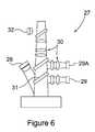
- FIG. 6is a schematic representation of an IR imager and projector forming part of an exemplary embodiment of a system for detection of catheter location for intravenous access;
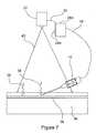
- FIG. 7is a schematic representation of a system for detection of catheter location for intravenous access, incorporating the catheter of FIGS. 2-5 and the IR imager and projector of FIG. 6 , according to a further embodiment.
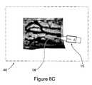
- FIGS. 8A , 8 B and 8 Cshow images projected onto the arm of a patient using the system of FIG. 7 .
- FIG. 1A conventional prior art catheter 10 for peripheral IV access is shown in FIG. 1 , including a catheter housing 12 sheathed over an introducer needle 14 , which terminates in a needle housing 16 .
- the introducer needle 14is used to insert the catheter into a vein. Once the vein is cannulated, the introducer needle 14 is removed leaving the catheter 10 in place.
- the IV catheter 10 of FIG. 1can be illuminated via a fibre optic light guide 18 disposed within the needle 14 .
- the light guideis illuminated from the needle housing 16 and propagates light to the needle tip 15 .
- a source of illumination or illuminator(discussed in greater detail with reference to FIGS. 6 and 7 ) generates light at a wavelength chosen to be transparent to tissue but readily absorbed by haemoglobin. Wavelengths in the range of 650-1100 nm are suitable.
- the illuminatorcan be a laser, LED or other suitable light source, and can be disposed within housing 16 or can be connected to the housing from a remote location via optical fibre 19 and a light source coupler 20 .
- the coupler 20ensures accurate alignment between the light-generating tip of the optical fibre 19 and the light guide 18 .
- the use of a remote illuminatoralso eliminates any obtrusion around the catheter, for ease of insertion.
- the hollow needle 14is used as a light guide such that no fibre 18 is required.
- the light source coupler 20mounts directly to the needle housing 16 and self-aligns with the back of the needle 14 . Light propagates down the needle shaft and is reflected out at the sharp side of the needle 14 .
- a window 24is molded into the plastic needle housing 16 .
- the purpose of the window 24is to create a blood flashback chamber that can be used as a visual detector for cannulation while preventing blood from contaminating the light source coupler 20 .
- a plano-convex lens 25is provided having a suitable radius to match the fibre numerical aperture output of optical fibre 19 for enhanced optical coupling into the needle 14 .
- the lens 25can be molded into the optical window 24 as part of the manufacturing process.
- the lens 25focuses the diverging light emitted from the optical fibre 19 to a point at the opening in the end of the needle 14 . This ensures maximum light coupling and light transmission to the needle tip 15 .
- a self-centering mechanism 26is provided in the walls of the needle housing 16 to ensure the light source coupler 20 self centers to the optical window 24 and lens 25 .
- Thiscan be accomplished using a slight taper to the needle housing walls that matches the light source coupler. In this way, the coupler self centers but can also be “locked” in place by friction.
- a quarter-turn thread(not shown) can also be used to attach the light coupler 20 .
- a matching thread(not shown) is placed on the needle housing 16 to engage the light coupler 20 .
- FIG. 6is a schematic representation of a modified version of a VeinViewer® infrared detector and image projector 27 manufactured and sold by Christie Medical Holdings, Inc., as discussed above, for incorporation into the system of FIG. 7 , discussed in greater detail below.
- the infrared detector and image projector 27is described in detail in the patents and patent applications referred to above.
- infrared detector and image projector 27comprises an IR illuminator 28 , an IR imager 29 , image processing circuitry and imaging optics 30 and a projector 32 .
- the IR lightilluminates a patient's tissue with light in the range of 650-1100 nm, which is absorbed by haemoglobin.
- the unabsorbed lightis reflected back and is detected by the IR imager 29 .
- the reflected imageis processed by image processing circuitry and imaging optics 30 , and then re-projected back in real-time via the projector 32 to show the location of blood vessels beneath the patient's skin.
- the IR imager 29includes a cut-off filter to differentiate reflected imaging light from background IR light in the environment.
- an additional IR illuminator 28 Amay be provided for illuminating the IV catheter 10
- a second IR imager 29 A and optical separator 31may be provided for detecting light reflected from illuminator 28 A.
- the modified system of FIG. 6may be combined with the IV catheter 10 of any one of FIG. 2 or 5 , to create a system for detection of catheter location for intravenous access, as shown in FIG. 7 .
- the infrared detector and image projector 27is connected to additional IR illuminator 28 A via a USB cable 33 , which illuminates the IV catheter 10 via optical fibre 19 and light source coupler 20 ( FIGS. 2-5 ).
- the wavelength of illumination of this additional light sourceis also in the range of 650-1100 nm but at a second wavelength that is different than the first wavelength output from the IR illuminator 28 , and is preferably separated from the first wavelength by at least 50 nm.
- Light 34 emanating from the tip 15 of the catheteris filtered by optical separator 31 and detected by the IR imager 29 A.
- Imagers 29 and 29 Atherefore detect both the image of the veins and the image of the catheter simultaneously. Both detectors are preferably identical in aspect ratio and resolution to ensure proper image alignment between the two images.
- the catheter housing 16is also detectable by the IR imager 29 A for orienting the axis of the needle in space.
- the infrared detector and image projector 27can project an image 40 onto the surface of the skin showing the location of the needle 14 relative to the tissue 36 and vein 38 in the image map, for example by illuminating the IV catheter 10 in a different color from the rest of the image, as shown in FIGS. 8A-8C .
- the illuminated tip 15continues to be detected by the IR imager 29 A of infrared detector and image projector 27 since the chosen wavelength is not readily absorbed by tissue.
- the infrared detector and image projector 27maintains a projection of the entire needle so that the clinician has a visual reference of the needle position relative to the vein 38 .
- bloodflashes back through the needle, as described above. Since blood is a good absorber of wavelengths in the range of 650-1000 nm, the light emanating from the needle tip 15 diminishes substantially.
- the IR imager 29 Aeventually detects a condition wherein no light is detected. This condition is fed back to the image processing circuitry which in response changes the color on the needle projection to indicate to the clinician that the needle has entered the bloodstream. Additional information can also be added via text on the image to indicate to the operator that the blood vessel is cannulated.
- Wavelength separationcan also be detected using a single IR imager 29 in at least one other way.
- the first and second wavelengthscan be separated using a mirror composed of two equal sized band-pass filters (not shown).
- the first filterreflects the primary wavelength onto one half of imager 29 and allows transmission of the second wavelength.
- the second filterreflects the secondary wavelength onto the other half of imager 29 and transmits the primary wavelength.
- each wavelengthmay be focussed onto one half of the imager.
- the two imaging halvesare partitioned to be identical in aspect ratio and resolution. The acquired images of either the veins or the catheter can then be processed and overlaid in the projected image to locate the catheter position.
- light pulse modulationmay be used to illuminate the catheter 10 but at the same wavelength of light as generated by the IR illuminator 28 .
- the imager 29acquires images at a speed of between 20-30 frames per second.
- this speedis maintained in duplex, which means alternating images of the vein pattern and needle are acquired at a rate of 40-60 frames per second.
- this higher acquisition speedreduces the amount of light impinging on the imager and thus reduces signal/noise ratio.
- pixel binningcan be employed to reduce the resolution while improving the signal/noise ratio. If adequate signal/noise ratio cannot be achieved at 40-60 frames per second then a lower frame rate of 20-30 frames per second can be used, although this will introduce visible lag into the projected image.
- the image of the vein map and catheterare separated by sequentially pulsing the IR illuminator 28 and the IR illuminator 28 A for the IV catheter 10 so that the IR imager 29 sees only one of either the vein image or the IV catheter image at any point in time.
- the infrared imager 29 and image projector 27can operate at the same wavelength for the vein image and the catheter image.
- the timing between the light pulses from IR illuminator 28 , the needle-tip IR illuminator 28 A, and the imager 29is synchronized such that the imager 29 is virtually shuttered to only acquire scattered or transmitted light from one of either the illuminator 28 or illuminator 28 A in sequential frames.
- Frame synchronizationcan be achieved in one of two ways.
- electronic synchronizationmay be provided by a microcontroller within the infrared detector and image projector 27 which communicates with and configures both IR illuminator 28 and IR imager 29 .
- This sequencingis used to cause the IR illuminator 28 to illuminate during frame capture A and to turn off during frame capture B.
- a sync signalcan also be output over the USB cable 33 so as to cause illuminator 28 A to illuminate the external needle tip 15 during frame capture B and be turned off during frame capture A.
- optical synchronizationmay be provided using the same synchronization pattern as set forth above, but using an optical signal.
- the needle-tip illuminator 28 Ais disposed in close proximity to the infrared detector and image projector 27 , such that when the illuminator 28 is turned on (frame capture A), the IR imager 29 detects this light and trips a switch to turn off the needle-tip illuminator 28 A.
- a final and simpler method to differentiate light received from illuminators 28 and 28 Ais to use intensity filtering. Instead of using two IR imagers 29 and 29 A for detecting reflected light projected onto the patient by the illuminators 28 and 28 A at different wavelengths, a single IR imager 29 can be used to detect reflected light projected onto the patient by the illuminators 28 and 28 A at the same wavelength but at different amplitudes or intensities. Light from illuminator 28 A can be made brighter than light from illuminator 28 , which is detected by IR imager 29 and re-projected back on to the patient's skin via projector 32 with the catheter needle being distinguishable by its higher brightness.
- the light from the needle tip 15is much brighter and more concentrated than the diffuse scattered light that is back-scattered from the bulk tissue around veins. This difference in relative brightness can be used by image processing software and circuitry and grey scale filtering to allow the catheter housing 16 and needle 14 to be discerned from the background vein image. However, this technique reduces the overall dynamic range of the imaging system.
- FIGS. 8A-8Cshow vein map images acquired using the system of FIG. 7 , with images of the catheter 10 with the illuminated catheter tip 15 indicated using coloured projection.
- the tip 15may be shown in a first colour (e.g. red) prior to cannulation while FIG. 8B shows the tip 15 in a second colour (e.g. yellow) to indicate that vein cannulation has been achieved, and in FIG. 8C the catheter needle 14 is shown beneath the surface of the skin via a coloured line (e.g. yellow) for indicating orientation of the catheter in space.
- a first coloure.g. red
- FIG. 8Bshows the tip 15 in a second colour (e.g. yellow) to indicate that vein cannulation has been achieved
- the catheter needle 14is shown beneath the surface of the skin via a coloured line (e.g. yellow) for indicating orientation of the catheter in space.
- a coloured linee.g. yellow
- an optical plugcan be placed at the end of the needle to prevent blood flashback from contaminating the light source coupler 20 .
- the optical plugcan, for example, be a clear medically approved plastic window that is placed on the end of the needle 14 to allow light transmission down the hollow needle.
Landscapes
- Health & Medical Sciences (AREA)
- Life Sciences & Earth Sciences (AREA)
- Engineering & Computer Science (AREA)
- Heart & Thoracic Surgery (AREA)
- Molecular Biology (AREA)
- Biophysics (AREA)
- Pathology (AREA)
- Biomedical Technology (AREA)
- Veterinary Medicine (AREA)
- Medical Informatics (AREA)
- Physics & Mathematics (AREA)
- Surgery (AREA)
- Animal Behavior & Ethology (AREA)
- General Health & Medical Sciences (AREA)
- Public Health (AREA)
- Human Computer Interaction (AREA)
- Vascular Medicine (AREA)
- Infusion, Injection, And Reservoir Apparatuses (AREA)
- Media Introduction/Drainage Providing Device (AREA)
Abstract
Description
Claims (24)
Priority Applications (4)
| Application Number | Priority Date | Filing Date | Title |
|---|---|---|---|
| US13/170,498US9247906B2 (en) | 2011-06-28 | 2011-06-28 | Method and apparatus for detection of catheter location for intravenous access |
| EP12153024.0AEP2540214B1 (en) | 2011-06-28 | 2012-01-30 | Apparatus for detection of catheter location for intravenous access |
| CN2012100609542ACN102846308A (en) | 2011-06-28 | 2012-03-09 | Method and apparatus for detection of catheter location for intravenous access |
| JP2012110436AJP6054056B2 (en) | 2011-06-28 | 2012-05-14 | Method and apparatus for detecting the position of a catheter for intravenous access |
Applications Claiming Priority (1)
| Application Number | Priority Date | Filing Date | Title |
|---|---|---|---|
| US13/170,498US9247906B2 (en) | 2011-06-28 | 2011-06-28 | Method and apparatus for detection of catheter location for intravenous access |
Publications (2)
| Publication Number | Publication Date |
|---|---|
| US20130006178A1 US20130006178A1 (en) | 2013-01-03 |
| US9247906B2true US9247906B2 (en) | 2016-02-02 |
Family
ID=45558579
Family Applications (1)
| Application Number | Title | Priority Date | Filing Date |
|---|---|---|---|
| US13/170,498Active2031-11-30US9247906B2 (en) | 2011-06-28 | 2011-06-28 | Method and apparatus for detection of catheter location for intravenous access |
Country Status (4)
| Country | Link |
|---|---|
| US (1) | US9247906B2 (en) |
| EP (1) | EP2540214B1 (en) |
| JP (1) | JP6054056B2 (en) |
| CN (1) | CN102846308A (en) |
Families Citing this family (42)
| Publication number | Priority date | Publication date | Assignee | Title |
|---|---|---|---|---|
| US8838210B2 (en)* | 2006-06-29 | 2014-09-16 | AccuView, Inc. | Scanned laser vein contrast enhancer using a single laser |
| US8715233B2 (en)* | 2011-12-21 | 2014-05-06 | The Board Of Trustees Of The Leland Stanford Junior University | Assistive method and visual-aid device for vascular needle insertion |
| US9792836B2 (en) | 2012-10-30 | 2017-10-17 | Truinject Corp. | Injection training apparatus using 3D position sensor |
| EP2915157B1 (en) | 2012-10-30 | 2019-05-08 | Truinject Corp. | System for injection training |
| WO2014176485A1 (en)* | 2013-04-26 | 2014-10-30 | West Virginia High Technology Consortium Foundation, Inc. | Facial recognition method and apparatus |
| TWI514988B (en)* | 2013-07-02 | 2016-01-01 | 臺北榮民總醫院 | Needle combination over lightwand puncture and method of using the same |
| WO2015001807A1 (en)* | 2013-07-05 | 2015-01-08 | パナソニックIpマネジメント株式会社 | Projection system |
| WO2015056257A1 (en)* | 2013-10-14 | 2015-04-23 | Avraham Aharoni | Device and system for imaging veins |
| JPWO2015072047A1 (en)* | 2013-11-14 | 2017-03-16 | パナソニックIpマネジメント株式会社 | Projection system |
| WO2015109251A1 (en) | 2014-01-17 | 2015-07-23 | Truinject Medical Corp. | Injection site training system |
| US20150297115A1 (en)* | 2014-02-04 | 2015-10-22 | Medical Components, Inc. | Light based location and identification of implanted medical devices |
| EP3415188A3 (en) | 2014-08-15 | 2019-05-01 | Sanofi-Aventis Deutschland GmbH | An injection device and a supplemental device configured for attachment thereto |
| CN104887181A (en)* | 2015-04-29 | 2015-09-09 | 浙江大学 | Portable vein projector |
| CN204889142U (en)* | 2015-09-01 | 2015-12-23 | 浙江永强集团股份有限公司 | Solar energy multi function table |
| WO2017070391A2 (en) | 2015-10-20 | 2017-04-27 | Truinject Medical Corp. | Injection system |
| WO2017151441A2 (en) | 2016-02-29 | 2017-09-08 | Truinject Medical Corp. | Cosmetic and therapeutic injection safety systems, methods, and devices |
| WO2017151963A1 (en) | 2016-03-02 | 2017-09-08 | Truinject Madical Corp. | Sensory enhanced environments for injection aid and social training |
| WO2017151716A1 (en) | 2016-03-02 | 2017-09-08 | Truinject Medical Corp. | System for determining a three-dimensional position of a testing tool |
| US11478150B2 (en) | 2016-03-28 | 2022-10-25 | Becton, Dickinson And Company | Optical fiber sensor |
| US10850046B2 (en) | 2016-03-28 | 2020-12-01 | Becton, Dickinson And Company | Cannula locator device |
| US10835718B2 (en)* | 2016-03-28 | 2020-11-17 | Becton, Dickinson And Company | Cannula with light-emitting optical fiber |
| US10269266B2 (en) | 2017-01-23 | 2019-04-23 | Truinject Corp. | Syringe dose and position measuring apparatus |
| CN109247910B (en)* | 2017-07-12 | 2020-12-15 | 京东方科技集团股份有限公司 | Blood vessel display device and blood vessel display method |
| US10935376B2 (en)* | 2018-03-30 | 2021-03-02 | Koninklijke Philips N.V. | System and method for 3D scanning |
| CN109044498B (en)* | 2018-06-20 | 2021-03-05 | 复旦大学附属中山医院 | Arterial puncture system and method for determining arterial puncture position |
| US11666203B2 (en)* | 2018-10-04 | 2023-06-06 | Biosense Webster (Israel) Ltd. | Using a camera with an ENT tool |
| CN109171905B (en)* | 2018-10-11 | 2020-06-30 | 青岛浦利医疗技术有限公司 | Puncture guiding device based on infrared imaging |
| WO2020088749A1 (en)* | 2018-10-30 | 2020-05-07 | OMARA, Mohamed | Endo-transillumination intravenous cannula needle device |
| KR102166115B1 (en)* | 2018-11-19 | 2020-10-15 | 이선주 | Luminous syringe |
| CN110123276A (en)* | 2019-05-17 | 2019-08-16 | 兰州大学 | A red light assisted puncture device |
| CN110694150A (en)* | 2019-10-22 | 2020-01-17 | 程基才 | Intelligent multifunctional vein angiography instrument |
| CN110841139A (en)* | 2019-12-10 | 2020-02-28 | 深圳市中科微光医疗器械技术有限公司 | Remaining needle capable of realizing needle tip positioning in image environment |
| JP7569837B2 (en)* | 2020-03-12 | 2024-10-18 | テルモ株式会社 | Puncture needle, catheter assembly, and blood vessel puncture system |
| JP7618648B2 (en)* | 2020-03-23 | 2025-01-21 | テルモ株式会社 | Puncture needle, catheter assembly, and blood vessel puncture system |
| CN111513822B (en)* | 2020-04-29 | 2022-02-25 | 周彬 | Auxiliary imbedding device for arteriovenous internal fistula indwelling needle |
| KR102852808B1 (en)* | 2020-07-17 | 2025-08-29 | 재단법인대구경북과학기술원 | System for tracking position and posture of needle |
| US12409302B2 (en)* | 2020-07-22 | 2025-09-09 | Becton, Dickinson And Company | Catheter position indicator and related systems and method |
| WO2022072727A2 (en)* | 2020-10-02 | 2022-04-07 | Bard Access Systems, Inc. | Ultrasound systems and methods for sustained spatial attention |
| WO2022176880A1 (en)* | 2021-02-22 | 2022-08-25 | テルモ株式会社 | Blood vessel puncture device and blood vessel puncture system |
| WO2024070898A1 (en)* | 2022-09-27 | 2024-04-04 | テルモ株式会社 | Blood vessel piercing device and blood vessel piercing system |
| WO2025057797A1 (en)* | 2023-09-15 | 2025-03-20 | テルモ株式会社 | Blood vessel puncture device and blood vessel puncture system |
| WO2025164222A1 (en)* | 2024-01-29 | 2025-08-07 | テルモ株式会社 | Puncture system, information processing method, and computer program |
Citations (23)
| Publication number | Priority date | Publication date | Assignee | Title |
|---|---|---|---|---|
| US4817622A (en) | 1986-07-22 | 1989-04-04 | Carl Pennypacker | Infrared imager for viewing subcutaneous location of vascular structures and method of use |
| WO1994017732A1 (en) | 1993-02-11 | 1994-08-18 | Fontenot Mark G | Detection of anatomic passages using infrared emitting catheter |
| CN1117707A (en) | 1993-02-11 | 1996-02-28 | 马克·G·方特诺特 | Detection of Tissue Channels Using Infrared Radiation Catheters |
| US5519208A (en) | 1994-09-29 | 1996-05-21 | Esparza; Joel | Infrared aided method and apparatus for venous examination |
| US5608210A (en) | 1994-09-29 | 1997-03-04 | Esparza; Joel | Infrared aided method and apparatus for venous examination |
| US6178340B1 (en) | 1998-08-24 | 2001-01-23 | Eduardo Svetliza | Three-dimensional infrared imager for subcutaneous puncture and study of vascular network |
| WO2002103409A2 (en) | 2001-06-19 | 2002-12-27 | The Trustees Of The University Of Pennsylvania | Optical guidance system for invasive catheter placement |
| US20040019280A1 (en) | 2001-02-12 | 2004-01-29 | Milton Waner | Infrared assisted monitoring of a catheter |
| JP2004237051A (en) | 2003-02-06 | 2004-08-26 | Ogawa Hiroteru | Blood vessel visualizing method and apparatus |
| US20060036164A1 (en) | 2001-06-19 | 2006-02-16 | The Trustees Of The University Of Pennsylvania | Optically guided system for precise placement of a medical catheter in a patient |
| US20060036167A1 (en) | 2004-07-03 | 2006-02-16 | Shina Systems Ltd. | Vascular image processing |
| US20060122515A1 (en) | 2000-01-19 | 2006-06-08 | Luminetx Corporation | Projection of subsurface structure onto an object's surface |
| US20060173351A1 (en)* | 2005-01-03 | 2006-08-03 | Ronald Marcotte | System and method for inserting a needle into a blood vessel |
| US7239909B2 (en) | 2000-01-19 | 2007-07-03 | Luminetx Technologies Corp. | Imaging system using diffuse infrared light |
| US20070158569A1 (en) | 2000-01-19 | 2007-07-12 | Luminetx Technologies Corporation | Method and Apparatus for Projection of Subsurface Structure onto an Object's Surface |
| US20080039715A1 (en) | 2004-11-04 | 2008-02-14 | Wilson David F | Three-dimensional optical guidance for catheter placement |
| US20080194930A1 (en) | 2007-02-09 | 2008-08-14 | Harris Melvyn L | Infrared-visible needle |
| US20100051808A1 (en) | 2007-10-19 | 2010-03-04 | Luminetx Corporation | Imaging System Using Infrared Light |
| US20100094126A1 (en) | 2005-09-13 | 2010-04-15 | Children's Medical Center Corporation | Light-guided transluminal catheter |
| CN201469867U (en) | 2009-07-30 | 2010-05-19 | 陈永曦 | Open type indwelling needle with protective sleeve |
| US20110009738A1 (en) | 2009-07-09 | 2011-01-13 | Becton, Dickinson And Company | System and method for visualizing needle entry into a body |
| US7930014B2 (en) | 2005-01-11 | 2011-04-19 | Volcano Corporation | Vascular image co-registration |
| US20110125028A1 (en) | 2009-07-22 | 2011-05-26 | Fred Wood | Vein scanner |
Family Cites Families (1)
| Publication number | Priority date | Publication date | Assignee | Title |
|---|---|---|---|---|
| US8812080B2 (en)* | 2009-06-10 | 2014-08-19 | Koninklijke Philips N.V. | Algorithm for photonic needle console |
- 2011
- 2011-06-28USUS13/170,498patent/US9247906B2/enactiveActive
- 2012
- 2012-01-30EPEP12153024.0Apatent/EP2540214B1/enactiveActive
- 2012-03-09CNCN2012100609542Apatent/CN102846308A/enactivePending
- 2012-05-14JPJP2012110436Apatent/JP6054056B2/ennot_activeExpired - Fee Related
Patent Citations (24)
| Publication number | Priority date | Publication date | Assignee | Title |
|---|---|---|---|---|
| US4817622A (en) | 1986-07-22 | 1989-04-04 | Carl Pennypacker | Infrared imager for viewing subcutaneous location of vascular structures and method of use |
| WO1994017732A1 (en) | 1993-02-11 | 1994-08-18 | Fontenot Mark G | Detection of anatomic passages using infrared emitting catheter |
| CN1117707A (en) | 1993-02-11 | 1996-02-28 | 马克·G·方特诺特 | Detection of Tissue Channels Using Infrared Radiation Catheters |
| US5519208A (en) | 1994-09-29 | 1996-05-21 | Esparza; Joel | Infrared aided method and apparatus for venous examination |
| US5608210A (en) | 1994-09-29 | 1997-03-04 | Esparza; Joel | Infrared aided method and apparatus for venous examination |
| US6178340B1 (en) | 1998-08-24 | 2001-01-23 | Eduardo Svetliza | Three-dimensional infrared imager for subcutaneous puncture and study of vascular network |
| US20060122515A1 (en) | 2000-01-19 | 2006-06-08 | Luminetx Corporation | Projection of subsurface structure onto an object's surface |
| US20070158569A1 (en) | 2000-01-19 | 2007-07-12 | Luminetx Technologies Corporation | Method and Apparatus for Projection of Subsurface Structure onto an Object's Surface |
| US7239909B2 (en) | 2000-01-19 | 2007-07-03 | Luminetx Technologies Corp. | Imaging system using diffuse infrared light |
| US20040019280A1 (en) | 2001-02-12 | 2004-01-29 | Milton Waner | Infrared assisted monitoring of a catheter |
| WO2002103409A2 (en) | 2001-06-19 | 2002-12-27 | The Trustees Of The University Of Pennsylvania | Optical guidance system for invasive catheter placement |
| US20060036164A1 (en) | 2001-06-19 | 2006-02-16 | The Trustees Of The University Of Pennsylvania | Optically guided system for precise placement of a medical catheter in a patient |
| CN1602168A (en) | 2001-06-19 | 2005-03-30 | 宾夕法尼亚大学理事会 | Light Guidance System for Invasive Catheter Positioning |
| JP2004237051A (en) | 2003-02-06 | 2004-08-26 | Ogawa Hiroteru | Blood vessel visualizing method and apparatus |
| US20060036167A1 (en) | 2004-07-03 | 2006-02-16 | Shina Systems Ltd. | Vascular image processing |
| US20080039715A1 (en) | 2004-11-04 | 2008-02-14 | Wilson David F | Three-dimensional optical guidance for catheter placement |
| US20060173351A1 (en)* | 2005-01-03 | 2006-08-03 | Ronald Marcotte | System and method for inserting a needle into a blood vessel |
| US7930014B2 (en) | 2005-01-11 | 2011-04-19 | Volcano Corporation | Vascular image co-registration |
| US20100094126A1 (en) | 2005-09-13 | 2010-04-15 | Children's Medical Center Corporation | Light-guided transluminal catheter |
| US20080194930A1 (en) | 2007-02-09 | 2008-08-14 | Harris Melvyn L | Infrared-visible needle |
| US20100051808A1 (en) | 2007-10-19 | 2010-03-04 | Luminetx Corporation | Imaging System Using Infrared Light |
| US20110009738A1 (en) | 2009-07-09 | 2011-01-13 | Becton, Dickinson And Company | System and method for visualizing needle entry into a body |
| US20110125028A1 (en) | 2009-07-22 | 2011-05-26 | Fred Wood | Vein scanner |
| CN201469867U (en) | 2009-07-30 | 2010-05-19 | 陈永曦 | Open type indwelling needle with protective sleeve |
Non-Patent Citations (2)
| Title |
|---|
| Corresponding Chinese Patent Application No. 201210060954.2, "First Office Action-with English Translation" dated Dec. 2, 2014. |
| Corresponding European Patent Application No. 12153024.0 Search Report dated Sep. 24, 2012. |
Also Published As
| Publication number | Publication date |
|---|---|
| EP2540214B1 (en) | 2014-01-22 |
| US20130006178A1 (en) | 2013-01-03 |
| CN102846308A (en) | 2013-01-02 |
| JP2013009949A (en) | 2013-01-17 |
| JP6054056B2 (en) | 2016-12-27 |
| EP2540214A1 (en) | 2013-01-02 |
Similar Documents
| Publication | Publication Date | Title |
|---|---|---|
| US9247906B2 (en) | Method and apparatus for detection of catheter location for intravenous access | |
| US8649848B2 (en) | Synchronization of illumination source and sensor for improved visualization of subcutaneous structures | |
| US8255040B2 (en) | Micro vein enhancer | |
| US20240335165A1 (en) | Scanned Laser Vein Contrast Enhancer with Image Averaging | |
| US20160256101A1 (en) | Device and System Device and System for Imaging Veins | |
| EP1841361B1 (en) | System for inserting a needle into a blood vessel | |
| CN103417196B (en) | Venous visualizer and visualizing method | |
| US8380291B2 (en) | Scanned laser vein contrast enhancer | |
| US11330968B2 (en) | Sterile endoscope sheath | |
| US20100061598A1 (en) | Apparatus and method for recognizing subcutaneous vein pattern | |
| US20210007589A1 (en) | Guided endotracheal intubation system | |
| US20080021329A1 (en) | Scanned laser vein contrast enhancer | |
| GB2524655A (en) | Ophthalmologic imaging apparatus and optical unit attachable to the same | |
| JP2006102110A (en) | Blood vessel position presentation device | |
| US9686484B2 (en) | Apparatus for acquiring and projecting broadband image capable of implementing visible light optical image and invisible light fluorescence image together | |
| US11638558B2 (en) | Micro vein enhancer | |
| US12295744B2 (en) | Micro vein enhancer with two lasers and two optical detectors configured for removing surface topology | |
| KR20160069233A (en) | Vascular Venous Identification System And Its Methods | |
| JP3149462B2 (en) | Eye camera | |
| CN104799829A (en) | Vein imaging system | |
| KR20180129324A (en) | System for recogniting epidural space | |
| EP4572656A1 (en) | Improvements in or relating to remotely capturing biometric data | |
| GB2620662A (en) | Improvements in or relating to remotely capturing biometric data | |
| WO2024086249A1 (en) | Devices, systems, and methods for imaging using shortwave infrared light | |
| WO2017085549A2 (en) | Guided endotracheal intubation system |
Legal Events
| Date | Code | Title | Description |
|---|---|---|---|
| AS | Assignment | Owner name:CHRISTIE DIGITAL SYSTEMS CANADA INC., CANADA Free format text:ASSIGNMENT OF ASSIGNORS INTEREST;ASSIGNORS:PINHO, GEORGE P.;WAGNER, ROBERT BENJAMIN;REEL/FRAME:026513/0936 Effective date:20110621 | |
| AS | Assignment | Owner name:CHRISTIE DIGITAL SYSTEMS USA, INC., CALIFORNIA Free format text:ASSIGNMENT OF ASSIGNORS INTEREST;ASSIGNOR:CHRISTIE DIGITAL SYSTEMS CANADA INC.;REEL/FRAME:027294/0883 Effective date:20111115 | |
| STCF | Information on status: patent grant | Free format text:PATENTED CASE | |
| AS | Assignment | Owner name:CHRISTIE MEDICAL HOLDINGS, INC., CALIFORNIA Free format text:ASSIGNMENT OF ASSIGNORS INTEREST;ASSIGNOR:CHRISTIE DIGITAL SYSTEMS USA, INC.;REEL/FRAME:048911/0620 Effective date:20190329 | |
| MAFP | Maintenance fee payment | Free format text:PAYMENT OF MAINTENANCE FEE, 4TH YEAR, LARGE ENTITY (ORIGINAL EVENT CODE: M1551); ENTITY STATUS OF PATENT OWNER: LARGE ENTITY Year of fee payment:4 | |
| MAFP | Maintenance fee payment | Free format text:PAYMENT OF MAINTENANCE FEE, 8TH YEAR, LARGE ENTITY (ORIGINAL EVENT CODE: M1552); ENTITY STATUS OF PATENT OWNER: LARGE ENTITY Year of fee payment:8 |