US9247498B2 - System and method for uplink timing synchronization in conjunction with discontinuous reception - Google Patents
System and method for uplink timing synchronization in conjunction with discontinuous receptionDownload PDFInfo
- Publication number
- US9247498B2 US9247498B2US14/795,441US201514795441AUS9247498B2US 9247498 B2US9247498 B2US 9247498B2US 201514795441 AUS201514795441 AUS 201514795441AUS 9247498 B2US9247498 B2US 9247498B2
- Authority
- US
- United States
- Prior art keywords
- srs
- active time
- drx
- drx active
- user equipment
- Prior art date
- Legal status (The legal status is an assumption and is not a legal conclusion. Google has not performed a legal analysis and makes no representation as to the accuracy of the status listed.)
- Active
Links
Images


Classifications
- H—ELECTRICITY
- H04—ELECTRIC COMMUNICATION TECHNIQUE
- H04W—WIRELESS COMMUNICATION NETWORKS
- H04W56/00—Synchronisation arrangements
- H—ELECTRICITY
- H04—ELECTRIC COMMUNICATION TECHNIQUE
- H04W—WIRELESS COMMUNICATION NETWORKS
- H04W52/00—Power management, e.g. Transmission Power Control [TPC] or power classes
- H04W52/02—Power saving arrangements
- H04W52/0209—Power saving arrangements in terminal devices
- H04W52/0212—Power saving arrangements in terminal devices managed by the network, e.g. network or access point is leader and terminal is follower
- H04W52/0216—Power saving arrangements in terminal devices managed by the network, e.g. network or access point is leader and terminal is follower using a pre-established activity schedule, e.g. traffic indication frame
- H—ELECTRICITY
- H04—ELECTRIC COMMUNICATION TECHNIQUE
- H04L—TRANSMISSION OF DIGITAL INFORMATION, e.g. TELEGRAPHIC COMMUNICATION
- H04L25/00—Baseband systems
- H04L25/02—Details ; arrangements for supplying electrical power along data transmission lines
- H04L25/0202—Channel estimation
- H04L25/0224—Channel estimation using sounding signals
- H—ELECTRICITY
- H04—ELECTRIC COMMUNICATION TECHNIQUE
- H04L—TRANSMISSION OF DIGITAL INFORMATION, e.g. TELEGRAPHIC COMMUNICATION
- H04L5/00—Arrangements affording multiple use of the transmission path
- H04L5/003—Arrangements for allocating sub-channels of the transmission path
- H04L5/0048—Allocation of pilot signals, i.e. of signals known to the receiver
- H—ELECTRICITY
- H04—ELECTRIC COMMUNICATION TECHNIQUE
- H04W—WIRELESS COMMUNICATION NETWORKS
- H04W52/00—Power management, e.g. Transmission Power Control [TPC] or power classes
- H04W52/02—Power saving arrangements
- H—ELECTRICITY
- H04—ELECTRIC COMMUNICATION TECHNIQUE
- H04W—WIRELESS COMMUNICATION NETWORKS
- H04W52/00—Power management, e.g. Transmission Power Control [TPC] or power classes
- H04W52/02—Power saving arrangements
- H04W52/0209—Power saving arrangements in terminal devices
- H—ELECTRICITY
- H04—ELECTRIC COMMUNICATION TECHNIQUE
- H04W—WIRELESS COMMUNICATION NETWORKS
- H04W56/00—Synchronisation arrangements
- H04W56/0005—Synchronisation arrangements synchronizing of arrival of multiple uplinks
- H—ELECTRICITY
- H04—ELECTRIC COMMUNICATION TECHNIQUE
- H04W—WIRELESS COMMUNICATION NETWORKS
- H04W56/00—Synchronisation arrangements
- H04W56/001—Synchronization between nodes
- H04W56/0015—Synchronization between nodes one node acting as a reference for the others
- H04W72/0413—
- H—ELECTRICITY
- H04—ELECTRIC COMMUNICATION TECHNIQUE
- H04W—WIRELESS COMMUNICATION NETWORKS
- H04W72/00—Local resource management
- H04W72/20—Control channels or signalling for resource management
- H04W72/21—Control channels or signalling for resource management in the uplink direction of a wireless link, i.e. towards the network
- H—ELECTRICITY
- H04—ELECTRIC COMMUNICATION TECHNIQUE
- H04W—WIRELESS COMMUNICATION NETWORKS
- H04W76/00—Connection management
- H04W76/20—Manipulation of established connections
- H04W76/28—Discontinuous transmission [DTX]; Discontinuous reception [DRX]
- H—ELECTRICITY
- H04—ELECTRIC COMMUNICATION TECHNIQUE
- H04W—WIRELESS COMMUNICATION NETWORKS
- H04W88/00—Devices specially adapted for wireless communication networks, e.g. terminals, base stations or access point devices
- H04W88/02—Terminal devices
- H—ELECTRICITY
- H04—ELECTRIC COMMUNICATION TECHNIQUE
- H04W—WIRELESS COMMUNICATION NETWORKS
- H04W88/00—Devices specially adapted for wireless communication networks, e.g. terminals, base stations or access point devices
- H04W88/08—Access point devices
- Y—GENERAL TAGGING OF NEW TECHNOLOGICAL DEVELOPMENTS; GENERAL TAGGING OF CROSS-SECTIONAL TECHNOLOGIES SPANNING OVER SEVERAL SECTIONS OF THE IPC; TECHNICAL SUBJECTS COVERED BY FORMER USPC CROSS-REFERENCE ART COLLECTIONS [XRACs] AND DIGESTS
- Y02—TECHNOLOGIES OR APPLICATIONS FOR MITIGATION OR ADAPTATION AGAINST CLIMATE CHANGE
- Y02D—CLIMATE CHANGE MITIGATION TECHNOLOGIES IN INFORMATION AND COMMUNICATION TECHNOLOGIES [ICT], I.E. INFORMATION AND COMMUNICATION TECHNOLOGIES AIMING AT THE REDUCTION OF THEIR OWN ENERGY USE
- Y02D30/00—Reducing energy consumption in communication networks
- Y02D30/70—Reducing energy consumption in communication networks in wireless communication networks
Definitions
- the applicationrelates to uplink timing synchronization in a wireless communication system.
- LTElong-term evolution
- the region in which a wireless device can gain access to a telecommunications networkmight be referred to by a name other than “cell”, such as “hot spot”.
- the term “cell”will be used to refer to any region in which a wireless device can gain access to a telecommunications network, regardless of whether the wireless device is a traditional cellular device, an LTE device, or some other device.
- Devices that might be used by users in a telecommunications networkcan include both mobile terminals, such as mobile telephones, personal digital assistants, handheld computers, portable computers, laptop computers, tablet computers and similar devices, and fixed terminals such as residential gateways, televisions, set-top boxes and the like. Such devices will be referred to herein as user equipment or UE.
- mobile terminalssuch as mobile telephones, personal digital assistants, handheld computers, portable computers, laptop computers, tablet computers and similar devices
- fixed terminalssuch as residential gateways, televisions, set-top boxes and the like.
- Such deviceswill be referred to herein as user equipment or UE.
- transmission from the network access equipment (e.g., eNB) to the UEis referred to as a downlink transmission.
- Communication from the UE to the network access equipmentis referred to as an uplink transmission.
- Wireless communication systemsgenerally require maintenance of timing synchronization to allow for continued communications. Maintaining uplink synchronization can be problematic, wasting throughput and/or decreasing battery life of an UE given that a UE may not always have data to transmit.
- FIG. 1is a schematic diagram of a cellular network according to an embodiment of the disclosure
- FIG. 2is a schematic diagram of a cell in a cellular network according to an embodiment of the disclosure
- FIG. 3is a schematic diagram of a possible uplink transmission channel
- FIG. 4is a signaling diagram between Network Access Equipment and a User Equipment
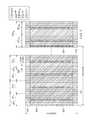
- FIG. 5Ais a timing diagram showing a first example of uplink timing reference signal timing having regard to discontinuous reception timing
- FIG. 5Bis a timing diagram showing a second example of uplink timing reference signal timing having regard to discontinuous reception timing
- FIG. 6Ais a flowchart corresponding to one UE embodiment
- FIG. 6Bis a flowchart corresponding to one network access equipment embodiment
- FIG. 7is a diagram of a wireless communications system including a mobile device operable for some of the various embodiments of the disclosure
- FIG. 8is a block diagram of a mobile device operable for some of the various embodiments of the disclosure.
- FIG. 9is a block diagram of a software environment that may be implemented on a mobile device operable for some of the various embodiments of the disclosure.
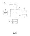
- FIG. 10is a block diagram of an exemplary general purpose computer according to one embodiment of the present disclosure.
- FIG. 11is an exemplary block diagram of modules in the User Equipment.
- FIG. 12is an exemplary block diagram of modules in the network access equipment.
- FIG. 1illustrates an exemplary cellular network 100 according to an embodiment of the disclosure.
- the cellular network 100may include a plurality of cells 102 1 , 102 2 , 102 3 , 102 4 , 102 5 , 102 6 , 102 7 , 102 8 , 102 9 , 102 10 , 102 11 , 102 12 , 102 13 , and 102 14 (collectively referred to as cells 102 ).
- each of the cells 102represents a coverage area for providing cellular services of the cellular network 100 through communication from a network access equipment (e.g., eNB).
- a network access equipmente.g., eNB
- While the cells 102are depicted as having non-overlapping coverage areas, persons of ordinary skill in the art will recognize that one or more of the cells 102 may have partially overlapping coverage with adjacent cells. In addition, while a particular number of the cells 102 are depicted, persons of ordinary skill in the art will recognize that a larger or smaller number of the cells 102 may be included in the cellular network 100 .
- One or more UEs 10may be present in each of the cells 102 . Although only one UE 10 is depicted and is shown in only one cell 102 12 , it will be apparent to one of skill in the art that a plurality of UEs 10 may be present in each of the cells 102 .
- a network access equipment 20 in each of the cells 102performs functions similar to those of a traditional base station. That is, the network access equipments 20 provide a radio link between the UEs 10 and other components in a telecommunications network. While the network access equipment 20 is shown only in cell 102 12 , it should be understood that network access equipment would be present in each of the cells 102 .
- a central control 110may also be present in the cellular network 100 to oversee some of the wireless data transmissions within the cells 102 .
- FIG. 2depicts a more detailed view of the cell 102 12 .
- the network access equipment 20 in cell 102 12may promote communication via a transmitting antenna 27 connected to a transmitter, a receiving antenna 29 connected to a receiver, and/or other well known equipment. Similar equipment might be present in the other cells 102 .
- a plurality of UEs 10( 10 a , 10 b , 10 c ) are present in the cell 102 12 , as might be the case in the other cells 102 .
- the cellular systems or cells 102are described as engaged in certain activities, such as transmitting signals; however, as will be readily apparent to one skilled in the art, these activities would in fact be conducted by components comprising the cells.
- the transmissions from the network access equipment 20 to the UEs 10are referred to as downlink transmissions, and the transmissions from the UEs 10 to the network access equipment 20 are referred to as uplink transmissions.
- the UEmay include any device that may communicate using the cellular network 100 .
- the UEmay include devices such as a cellular telephone, a laptop computer, a navigation system, or any other devices known to persons of ordinary skill in the art that may communicate using the cellular network 100 .
- the format of an uplink channelis shown schematically in FIG. 3 .
- the uplink channelis representative of a two dimensional time-frequency resource, in which frequency is indicated along the vertical axis and time, in the form of OFDM symbols, slots, sub-frames and frames are indicated on the horizontal axis.
- the transmissioncan be one of a number of different bandwidths (e.g., 1.25, 5, 15, or 20 MHz).
- the uplinkis broken into frames, sub-frames and slots.
- Each slot 201(shown as slots 201 1 , 201 2 , . . . , 201 19 , 201 20 , collectively slots 201 ) is made up of seven orthogonal frequency division multiplexed (OFDM) symbols 203 .
- OFDMorthogonal frequency division multiplexed
- Two slots 201make up a sub-frame 205 (sub-frames 205 1 , 205 2 , . . . , 205 10 , collectively are sub-frames 205 ).
- a frameis a collection of 10 contiguous sub-frames. Because the exact details of a sub-frame 205 may vary depending upon the exact implementation, the following description is provided as an example only.
- the UEwill transmit using a constant-amplitude and zero-autocorrelation (CAZAC) sequence so that more than one UE may transmit simultaneously.
- the demodulation (DM) reference symbol (RS)is placed on the fourth symbol 209 of each slot; and a control channel 211 is taken up by at least one resource block on the very outside edges of the frequency band.
- a sounding reference signalis considered to be an uplink timing reference signal transmission.
- SRSare made available at the beginning, or end, of each sub-frame 205 and is broken down into several blocks of 12 sub-carriers (not individually shown) that correspond to the same frequency bandwidth as a resource block.
- a UEmay use one or all of those frequency blocks depending on the transmission bandwidth selected.
- the UEmay also use every other sub-carrier in one or more multiple frequency blocks.
- the SRSis shown in the first symbol 207 of the sub-frame 205 1 and of sub-frame 201 19 .
- the transmission of SRSsis based on the time between subsequent SRS transmission by a single UE.
- PUCCHphysical uplink control channel
- HARQhybrid automatic repeat request
- NACKnegative acknowledgement
- An ACK or NACKis sent on the PUCCH 211 by the UE to the eNB to indicate whether a packet transmitted from the eNB was received at that UE.
- a physical uplink shared channel (PUSCH)is used to send user data.
- uplink channelis one implementation of an uplink channel. It will be appreciated that other uplink channel configurations may be used wherein an uplink timing reference signal transmission (e.g., SRS) is sent during any portion of the uplink message, not necessarily only at the beginning or end of a specified time interval (e.g., slot).
- SRSuplink timing reference signal transmission
- the network access equipment 20In order to maintain uplink synchronization, it is desirable for the network access equipment 20 (shown in FIG. 1 ) to calculate the uplink channel conditions by analyzing signals sent from the UE 10 .
- One possible signaling diagram of signals sent between the network access equipment 20 and the UE 10is shown in FIG. 4 .
- the network access equipment 20instructs the UE 10 when to send an uplink timing reference signal transmission (e.g., SRS), through use of an uplink timing reference signal transmission instruction message 241 .
- the uplink timing reference signal transmission instruction message 241may include any one of a variety of instructions.
- the network access equipment 20may instruct the UE 10 via the timing reference signal transmission instruction message 241 to send the timing reference signal transmissions at a constant rate, or in bursts depending on the velocity of the UE 10 relative to the network access equipment 20 .
- the UE 10may send the timing reference signal transmissions (e.g., SRS) in accordance with the instructions of the network access equipment 20 .
- the UEmay operate with discontinuous reception (DRX).
- DRXdiscontinuous reception
- the UEwill turn its reception capability on and off in a repeating fashion.
- the networkis aware of the DRX behavior and makes its transmission to the UE during periods that the reception capability is on.
- An “On” period followed by an “Off” periodis a DRX cycle.
- DRX in Connected Modewill be configured by the network.
- Part of the configurationis the setting of the DRX-cycle “On” Duration, inactivity timers and HARQ timer.
- the UEwill monitor the PDCCH (packet data control channel) or configured resource for the possible downlink transmissions.
- PDCCHpacket data control channel
- an inactivity timerwill be started.
- the UEmay go back to sleep according to the DRX configuration.
- the UEwill transmit the SRS (more generally an uplink timing reference signal) only during DRX “On” periods. During DRX “Off” periods, the UE does not transmit SRS. In some embodiments, this involves signalling the UE to transmit the SRS with a desired repetition period, and the UE transmitting the SRS for each repetition period only if it occurs during a DRX “On” period. Depending on the alignment or lack of alignment between the SRS repetition period and the DRX “On” periods, there may or may not be SRS repetition periods for which no SRS is transmitted. If the SRS is to be transmitted during each and every SRS repetition period, this will require that the DRX cycle be as frequent, or more frequent than the desired SRS repetition period.
- SRSmore generally an uplink timing reference signal
- FIG. 5Ashows a simple example of this where the SRS repetition period is a multiple (in this case the multiple is two) of the DRX cycle.
- the SRSis less frequent than the CQI.
- Indicated at 800is DRX timing in which there is a DRX cycle 802 that includes a DRX “On” Duration (indicated at 804 ) and a DRX “Off” Duration. The receiver is alternately turned on for “On” periods having the DRX “On” Duration and off for “Off” periods having the DRX “Off” Duration.
- Indicated at 810is the CQI timing.
- the CQIhas a CQI period 812 that is aligned with the DRX cycle.
- the CQIis sent during the DRX “On” periods.
- Indicated at 820is the timing of the SRS.
- the SRShas an SRS period 822 .
- the SRS period 822is double the DRX cycle 802 . As such, so long as these cycle durations are in place, the SRS can be sent at the desired SRS period during DRX “On” periods.
- the UEmakes its SRS transmission irrespective of DRX in certain conditions. This is particularly appropriate in order to maintain the uplink time alignment for different UE's with high velocity. This will allow an SRS period to be established that is shorter than the DRX cycle as might be the case when the DRX cycle is particularly long, and/or when the SRS period has become particularly short due to mobility of the UE.
- FIG. 5Bshows an example of an SRS period that is smaller than the DRX cycle. As discussed above, this situation may be more common when the UE moves to the longer DRX cycles. If UL synchronization is to be maintained even during the longer DRX cycle (for example the 640 ms DRX cycle), then the SRS needs to still be transmitted, and depending on the mobility of the UE, it may need to be transmitted at a higher frequency than the DRX cycle. With reference to FIG. 5B , the DRX timing 800 and CQI timing 810 are the same as in FIG. 5A .
- the SRS timing 820has an SRS period 840 that is half that of the CQI period 812 , and that is shorter than the DRX cycle 802 .
- the UEwill need to turn its transmitter on outside the normal DRX “On” periods in order to be able to transmit all of the SRS transmissions.
- a resourceis allocated for the UE to transmit the SRS, and this SRS resource is not released when the UE is not transmitting the SRS.
- an uplink timing alignment timeris employed.
- the timerrepresents the amount of time the UE is expected to be able to maintain uplink synchronization, after which it can be assumed that the UE should not transmit on the UL.
- the networktransmits a timing alignment update command to the UE each time it computes new uplink timing based on received SRS from the UE to instruct the UE how to adjust its timing alignment. Once alignment has been lost, the UE will need to regain alignment when it next needs to transmit.
- the uplink timing alignment timeris run by the network. If no timing alignment update command has been sent within the period that the timer is running, then the timer will expire, and it is assumed that alignment is lost. In this event, some or all resources (e.g. CQI, SRS) allocated for UL communication are released. The network will inform the UE of when the timer expires.
- resourcese.g. CQI, SRS
- the timermay run on the UE in which case the network may inform the UE of the timer value.
- the timeris reset by the reception of a timing alignment (TA) update command.
- TAtiming alignment
- the CQI and SRSare both transmitted during DRX “On” Durations, although not necessarily with the same frequency.
- transmission of SRS and CQIis configured to be in the same sub-frame whenever feasible.
- FIG. 3An example of this is shown in FIG. 3 where the CQI 213 is sent in the same sub-frame 201 1 as the SRS 207 .
- the SRS and CQIcan be transmitted in the same sub-frame for every second SRS transmission.
- the CQIis also only transmitted during DRX “On” durations.
- the CQIis allowed to be transmitted during DRX “On” durations and can be transmitted during periods that the transmitter has been turned on irrespective of DRX “On” durations for the purpose of transmitting SRS.
- the DTX (discontinuous transmission) periodsdo not necessarily align with the DRX periods. Once the SRS and CQI have been transmitted, the transmitter can be turned off, even though the receiver may still be on.
- FIGS. 5A and 5Balso each show timing of scheduling requests (SR), generally indicated at 830 .
- a scheduling requestis an indication sent by the UE to the base station to request the UL resource.
- the UEtransmits scheduling requests only during DRX “On” periods.
- the UEtransmits scheduling requests during a sub-frame that the transmitter is already on to transmit the CQI, the SRS or both. This can occur through network configuration of the UE, or at the initiative of the UE. Data may be sent from the UE during the DRX “On” period.
- FIG. 6Aillustrates a flow chart of a specific example of such a method for SRS transmission in a UE 10 .
- the method of FIG. 6Amight be executed continuously, or when there is a change in SRS period and/or DRX cycle for example.
- the SRS periodmay change as a function of mobility of the UE, whereas the DRX cycle may change as a function of level of communications activity involving the UE.
- the UEreceives an instruction from the network. If the instruction is to operate in the first operational mode (yes path, block 6 A- 2 ), the UE operates in the first operational mode at block 6 A- 3 . If there are no instructions to operate in the first operational mode (no path, block 6 A- 2 ), a subsequent decision involves determining whether there is an instruction to operate in the second operational mode. If the instruction is to operate in the second operational mode (yes path, block 6 A- 4 ), the UE operates in the second operational mode at block 6 A- 5 . More generally, in a first operational mode, the UE executes block 6 A- 3 and in a second operational mode, the UE executes block 6 A- 5 . The conditions for executing the first or second operational mode may be as described above, or may be different. In some implementations, only the first operational mode is provided, or only the second operational mode is provided.
- FIG. 6BA flowchart of such an embodiment from the network perspective is shown in FIG. 6B .
- the networkdetermines whether the UE should operate in the first operational mode or the second operational mode. This can be done as a function of mobility of the UE and/or channel utilization to name a few examples.
- the networksends an instruction to the UE to operate in the determined operational mode.
- the UE 10comprises a processor capable of performing the above process.
- the different functionshave been broken out into different modules. These modules may be implemented separately or together. Further, these modules may be implemented in hardware, software, or some combination. Finally, these modules may reside in different portions of the UE memory.
- the UE processorcomprises a receive module 801 , a determination module 803 , and a transmission module 807 .
- the receive module 801receives a message or messages indicating an operational mode for SRS transmission.
- the determination module 803determines the manner of transmitting the SRS having regard to the message.
- the determination moduleinforms the transmission module 807 to send the SRS in accordance with the determination made by the determination module 803 .
- the UEruns an uplink timing alignment timer as described above in which case the UE further comprises an uplink timing alignment timer module 809 .
- the timeris reset upon receipt of a timing alignment update message by the receive module 801 . If the timer expires, the UE releases the resource used for SRS transmission by the transmission module 807 .
- the receive module 801 of the UEreceives an instruction from the network that indicates timing has been lost in which case the UE releases the resource used for SRS transmission.
- the network access equipment 20also comprises a processor.
- the processorcomprises a receive module 901 , an evaluation module 903 and a transmission module 905 .
- these modulesare defined for simplicity, and may be executed in software, hardware, firmware, or both. Additionally, these modules may be stored in the same or different memories.
- the receiver module 901receives SRS messages, CQI and other signals from the UE.
- the evaluation module 903evaluates an appropriate DRX period and a desired SRS period. This may for example be done having regard to the activity of the UE, the mobility of the UE, and/or activity of the UE.
- the evaluation moduledetermines an appropriate SRS transmission behavior having regard to the DRX behavior and SRS repetition period and instructs the transmission module 905 to signal this to the UE.
- the networkruns an uplink timing alignment timer as described above in which case the processor further comprises an uplink timing alignment timer module 907 .
- the timeris reset upon transmission of a timing alignment update message by the transmission module 905 .
- the networksends an instruction to the UE to release the resource used for SRS transmission, and the network also releases the resource used for SRS transmission.
- the networkreleased the resource used for SRS transmission without sending a message to the UE.
- the networkmay have previously sent a timer value to the UE. Because the UE may have used that timer value to start its own uplink alignment timer, the UE would not need a message from the network informing the UE that the timer had expired and the SRS resource is to be released.
- FIG. 7illustrates a wireless communications system including an embodiment of the UE 10 .
- the UE 10is operable for implementing aspects of the disclosure, but the disclosure should not be limited to these implementations.
- the UE 10may take various forms including a wireless handset, a pager, a personal digital assistant (PDA), a portable computer, a tablet computer, or a laptop computer. Many suitable devices combine some or all of these functions.
- the UE 10is not a general purpose computing device like a portable, laptop or tablet computer, but rather is a special-purpose communications device such as a mobile phone, a wireless handset, a pager, a PDA, or a telecommunications device installed in a vehicle.
- the UE 10may be a portable, laptop or other computing device.
- the UE 10may support specialized activities such as gaming, inventory control, job control, and/or task management functions, and so on.
- the UE 10includes a display 402 .
- the UE 10also includes a touch-sensitive surface, a keyboard or other input keys generally referred as 404 for input by a user.
- the keyboardmay be a full or reduced alphanumeric keyboard such as QWERTY, Dvorak, AZERTY, and sequential types, or a traditional numeric keypad with alphabet letters associated with a telephone keypad.
- the input keysmay include a track wheel, an exit or escape key, a trackball, and other navigational or functional keys, which may be inwardly depressed to provide further input function.
- the UE 10may present options for the user to select, controls for the user to actuate, and/or cursors or other indicators for the user to direct.
- the UE 10may further accept data entry from the user, including numbers to dial or various parameter values for configuring the operation of the UE 10 .
- the UE 10may further execute one or more software or firmware applications in response to user commands. These applications may configure the UE 10 to perform various customized functions in response to user interaction. Additionally, the UE 10 may be programmed and/or configured over-the-air, for example from a wireless base station, a wireless access point, or a peer UE 10 .
- the various applications executable by the UE 10are a web browser, which enables the display 402 to show a web page.
- the web pagemay be obtained via wireless communications with a wireless network access node, a cell tower, a peer UE 10 , or any other wireless communication network or system 400 .
- the network 400is coupled to a wired network 408 , such as the Internet.
- the UE 10has access to information on various servers, such as a server 410 .
- the server 410may provide content that may be shown on the display 402 .
- the UE 10may access the network 400 through a peer UE 10 acting as an intermediary, in a relay type or hop type of connection.
- FIG. 8shows a block diagram of the UE 10 . While a variety of known components of UEs 10 are depicted, in an embodiment a subset of the listed components and/or additional components not listed may be included in the UE 10 .
- the UE 10includes a digital signal processor (DSP) 502 and a memory 504 .
- DSPdigital signal processor
- the UE 10may further include an antenna and front end unit 506 , a radio frequency (RF) transceiver 508 , an analog baseband processing unit 510 , a microphone 512 , an earpiece speaker 514 , a headset port 516 , an input/output interface 518 , a removable memory card 520 , a universal serial bus (USB) port 522 , a short range wireless communication sub-system 524 , an alert 526 , a keypad 528 , a liquid crystal display (LCD), which may include a touch sensitive surface 530 , an LCD controller 532 , a charge-coupled device (CCD) camera 534 , a camera controller 536 , and a global positioning system (GPS) sensor 538 .
- the UE 10may include another kind of display that does not provide a touch sensitive screen.
- the DSP 502may communicate directly with the memory 504 without passing through the input/output interface 518 .
- the DSP 502or some other form of controller or central processing unit operates to control the various components of the UE 10 in accordance with embedded software or firmware stored in memory 504 or stored in memory contained within the DSP 502 itself.
- the DSP 502may execute other applications stored in the memory 504 or made available via information carrier media such as portable data storage media like the removable memory card 520 or via wired or wireless network communications.
- the application softwaremay comprise a compiled set of machine-readable instructions that configure the DSP 502 to provide the desired functionality, or the application software may be high-level software instructions to be processed by an interpreter or compiler to indirectly configure the DSP 502 .
- the antenna and front end unit 506may be provided to convert between wireless signals and electrical signals, enabling the UE 10 to send and receive information from a cellular network or some other available wireless communications network or from a peer UE 10 .
- the antenna and front end unit 506may include multiple antennas to support beam forming and/or multiple input multiple output (MIMO) operations.
- MIMO operationsmay provide spatial diversity which can be used to overcome difficult channel conditions and/or increase channel throughput.
- the antenna and front end unit 506may include antenna tuning and/or impedance matching components, RF power amplifiers, and/or low noise amplifiers.
- the RF transceiver 508provides frequency shifting, converting received RF signals to baseband and converting baseband transmit signals to RF.
- a radio transceiver or RF transceivermay be understood to include other signal processing functionality such as modulation/demodulation, coding/decoding, interleaving/deinterleaving, spread ing/despreading, inverse fast Fourier transforming (IFFT)/fast Fourier transforming (FFT), cyclic prefix appending/removal, and other signal processing functions.
- IFFTinverse fast Fourier transforming
- FFTfast Fourier transforming
- cyclic prefix appending/removaland other signal processing functions.
- the description hereseparates the description of this signal processing from the RF and/or radio stage and conceptually allocates that signal processing to the analog baseband processing unit 510 and/or the DSP 502 or other central processing unit.
- the analog baseband processing unit 510may provide various analog processing of inputs and outputs, for example analog processing of inputs from the microphone 512 and the headset 516 and outputs to the earpiece 514 and the headset 516 .
- the analog baseband processing unit 510may have ports for connecting to the built-in microphone 512 and the earpiece speaker 514 that enable the UE 10 to be used as a cell phone.
- the analog baseband processing unit 510may further include a port for connecting to a headset or other hands-free microphone and speaker configuration.
- the analog baseband processing unit 510may provide digital-to-analog conversion in one signal direction and analog-to-digital conversion in the opposing signal direction.
- at least some of the functionality of the analog baseband processing unit 510may be provided by digital processing components, for example by the DSP 502 or by other central processing units.
- the DSP 502may perform modulation/demodulation, coding/decoding, interleaving/deinterleaving, spread ing/despreading, inverse fast Fourier transforming (IFFT)/fast Fourier transforming (FFT), cyclic prefix appending/removal, and other signal processing functions associated with wireless communications.
- IFFTinverse fast Fourier transforming
- FFTfast Fourier transforming
- cyclic prefix appending/removaland other signal processing functions associated with wireless communications.
- CDMAcode division multiple access
- the DSP 502may perform modulation, coding, interleaving, inverse fast Fourier transforming, and cyclic prefix appending, and for a receiver function the DSP 502 may perform cyclic prefix removal, fast Fourier transforming, deinterleaving, decoding, and demodulation.
- OFDMAorthogonal frequency division multiplex access
- the DSP 502may communicate with a wireless network via the analog baseband processing unit 510 .
- the communicationmay provide Internet connectivity, enabling a user to gain access to content on the Internet and to send and receive e-mail or text messages.
- the input/output interface 518interconnects the DSP 502 and various memories and interfaces.
- the memory 504 and the removable memory card 520may provide software and data to configure the operation of the DSP 502 .
- the interfacesmay be the USB interface 522 and the short range wireless communication sub-system 524 .
- the USB interface 522may be used to charge the UE 10 and may also enable the UE 10 to function as a peripheral device to exchange information with a personal computer or other computer system.
- the short range wireless communication sub-system 524may include an infrared port, a Bluetooth interface, an IEEE 802.11 compliant wireless interface, or any other short range wireless communication sub-system, which may enable the UE 10 to communicate wirelessly with other nearby mobile devices and/or wireless base stations.
- the input/output interface 518may further connect the DSP 502 to the alert 526 that, when triggered, causes the UE 10 to provide a notice to the user, for example, by ringing, playing a melody, or vibrating.
- the alert 526may serve as a mechanism for alerting the user to any of various events such as an incoming call, a new text message, and an appointment reminder by silently vibrating, or by playing a specific pre-assigned melody for a particular caller.
- the keypad 528couples to the DSP 502 via the interface 518 to provide one mechanism for the user to make selections, enter information, and otherwise provide input to the UE 10 .
- the keyboard 528may be a full or reduced alphanumeric keyboard such as QWERTY, Dvorak, AZERTY and sequential types, or a traditional numeric keypad with alphabet letters associated with a telephone keypad.
- the input keysmay include a track wheel, an exit or escape key, a trackball, and other navigational or functional keys, which may be inwardly depressed to provide further input function.
- Another input mechanismmay be the LCD 530 , which may include touch screen capability and also display text and/or graphics to the user.
- the LCD controller 532couples the DSP 502 to the LCD 530 .
- the CCD camera 534if equipped, enables the UE 10 to take digital pictures.
- the DSP 502communicates with the CCD camera 534 via the camera controller 536 .
- a camera operating according to a technology other than Charge Coupled Device camerasmay be employed.
- the GPS sensor 538is coupled to the DSP 502 to decode global positioning system signals, thereby enabling the UE 10 to determine its position.
- Various other peripheralsmay also be included to provide additional functions, e.g., radio and television reception.
- FIG. 9illustrates a software environment 602 that may be implemented by the DSP 502 .
- the DSP 502executes operating system drivers 604 that provide a platform from which the rest of the software operates.
- the operating system drivers 604provide drivers for the wireless device hardware with standardized interfaces that are accessible to application software.
- the operating system drivers 604include application management services (“AMS”) 606 that transfer control between applications running on the UE 10 .
- AMSapplication management services
- FIG. 9are also shown in FIG. 9 a web browser application 608 , a media player application 610 , and Java applets 612 .
- the web browser application 608configures the UE 10 to operate as a web browser, allowing a user to enter information into forms and select links to retrieve and view web pages.
- the media player application 610configures the UE 10 to retrieve and play audio or audiovisual media.
- the Java applets 612configure the UE 10 to provide games, utilities, and other functionality.
- a component 614might provide functionality related
- FIG. 10illustrates a typical, general-purpose computer system 700 that may be suitable for implementing one or more embodiments disclosed herein.
- the computer system 700includes a processor 720 (which may be referred to as a central processor unit or CPU) that is in communication with memory devices including secondary storage 750 , read only memory (ROM) 740 , random access memory (RAM) 730 , input/output (I/O) devices 710 , and network connectivity devices 760 .
- the processormay be implemented as one or more CPU chips.
- the secondary storage 750is typically comprised of one or more disk drives or tape drives and is used for non-volatile storage of data and as an over-flow data storage device if RAM 730 is not large enough to hold all working data. Secondary storage 750 may be used to store programs which are loaded into RAM 730 when such programs are selected for execution.
- the ROM 740is used to store instructions and perhaps data which are read during program execution. ROM 740 is a non-volatile memory device which typically has a small memory capacity relative to the larger memory capacity of secondary storage.
- the RAM 730is used to store volatile data and perhaps to store instructions. Access to both ROM 740 and RAM 730 is typically faster than to secondary storage 750 .
- I/O devices 710may include printers, video monitors, liquid crystal displays (LCDs), touch screen displays, keyboards, keypads, switches, dials, mice, track balls, voice recognizers, card readers, paper tape readers, or other well-known input devices.
- LCDsliquid crystal displays
- touch screen displayskeyboards, keypads, switches, dials, mice, track balls, voice recognizers, card readers, paper tape readers, or other well-known input devices.
- the network connectivity devices 760may take the form of modems, modem banks, ethernet cards, universal serial bus (USB) interface cards, serial interfaces, token ring cards, fiber distributed data interface (FDDI) cards, wireless local area network (WLAN) cards, radio transceiver cards such as code division multiple access (CDMA) and/or global system for mobile communications (GSM) radio transceiver cards, and other well-known network devices.
- These network connectivity 760 devicesmay enable the processor 720 to communicate with an Internet or one or more intranets. With such a network connection, it is contemplated that the processor 720 might receive information from the network, or might output information to the network in the course of performing the above-described method steps. Such information, which is often represented as a sequence of instructions to be executed using processor 720 , may be received from and outputted to the network, for example, in the form of a computer data signal embodied in a carrier wave.
- Such informationmay be received from and outputted to the network, for example, in the form of a computer data baseband signal or signal embodied in a carrier wave.
- the baseband signal or signal embodied in the carrier wave generated by the network connectivity 760 devicesmay propagate in or on the surface of electrical conductors, in coaxial cables, in waveguides, in optical media, for example optical fiber, or in the air or free space.
- the information contained in the baseband signal or signal embedded in the carrier wavemay be ordered according to different sequences, as may be desirable for either processing or generating the information or transmitting or receiving the information.
- the baseband signal or signal embedded in the carrier wave, or other types of signals currently used or hereafter developed, referred to herein as the transmission mediummay be generated according to several methods well known to one skilled in the art.
- the processor 720executes instructions, codes, computer programs, scripts which it accesses from hard disk, floppy disk, optical disk (these various disk-based systems may all be considered secondary storage 750 ), ROM 740 , RAM 730 , or the network connectivity devices 760 . While only one processor 720 is shown, multiple processors may be present. Thus, while instructions may be discussed as executed by a processor, the instructions may be executed simultaneously, serially, or otherwise executed by one or multiple processors.
- Radio Layer 1 and Radio Layer 2are standards related to Radio Layer 1 and Radio Layer 2, respectively.
- Radio Layer 1generally pertains to, but is not limited to, the physical layer of the radio interface for UE, UTRAN (UMTS Terrestrial Radio Access Network), Evolved UTRAN, and beyond and may cover both frequency divisional duplex (FDD) and time divisional duplex (TDD) modes of radio interface.
- Radio Layer 2generally pertains to, but is not limited to, radio interface architecture and protocols such as media access control (MAC), radio link control (RLC) and packet data convergence protocol (PDCP), specification of the Radio Resource Control protocol, and strategies of Radio Resource Management and the services provided by the physical layer to the upper layers).
- MACmedia access control
- RLCradio link control
- PDCPpacket data convergence protocol
- SRSsounding reference signals
- SRscheduling request
- SRIscheduling indicators
- SRSDownlink Reference Signal
- DRX in Connected Modewill be configured by the eNB.
- Part of the configurationis the setting of the DRX-cycle “On” Duration, inactivity timers and HARQ timer.
- “On” DurationUE will monitor the PDCCH or configured resource for the possible downlink transmissions.
- an inactivity timerwill be started.
- UEmay go back to sleep according to the configurations.
- a length of long DRX cycleis a determiner in how to allow the UE to move into an unsynchronized state. It is conceivable that a DRX cycle greater than 1 second could lead to loss of UL synchronization. At such a point, all SRS and CQI transmissions on the UL should be terminated and the UE should access the random access channel (RACH) whenever data needs to flow in the UL.
- RACHrandom access channel
- mobilityhas a direct impact on UL synchronization loss. If the unsynchronized state has not been entered, the SRS transmission must continue as needed. Under modest mobility conditions (e.g. 30 kilometers/hour), the SRS period may be on the order of 50 ms. This is less than several of the shorter DRX cycles. Synchronization is to be maintained if any uplink transmissions are to take place.
- the UEwill transmit the SRS during the appropriate “On” Duration. In the “Off” Duration, the UE may not transmit SRS. Furthermore, to simplify the procedure by avoiding frequent reassignment or release, the SRS resource should not be released when the UE is not transmitting the SRS. In some embodiments, the SRS resource is only released when an uplink timing alignment timer expires.
- the UEtransmits the SRS during the DRX “On” Duration, and SRS transmissions may be stopped during the off duration.
- the resource for the SRSis maintained during the DRX and released only when the uplink timing alignment timer has expired.
- transmission of SRS and CQIoccur in the same sub-frame whenever feasible.
- the eNBis enabled to configure the UE for the SRS transmission irrespective of DRX in certain conditions.
- transmission of SRS and CQIis in the same sub-frame whenever feasible to save UE's battery power.
- the eNBconfigures the UE to transmit SRS irrespective of the DRX.
- FIG. 5Ashows the case when the SRS period is less frequent than CQI.
- FIG. 5Bshows the opposite case.
- the eNBselects an SRS transmission periodicity that is smaller than the DRX cycle. This situation will be more common when the UE moves to the longer DRX cycles. If UL synchronization must be maintained even during the longer DRX cycle, for example 640 ms or more, then the SRS is transmitted.
- methods and devices described hereinare for use in long term evolution (LTE) networks.
- LTElong term evolution
- the devices and methods described hereinare not intended to be limited to only LTE networks.
- the methods and devices described hereinare for use with other types of communication networks.
Landscapes
- Engineering & Computer Science (AREA)
- Signal Processing (AREA)
- Computer Networks & Wireless Communication (AREA)
- Power Engineering (AREA)
- Mobile Radio Communication Systems (AREA)
- Synchronisation In Digital Transmission Systems (AREA)
Abstract
Description
Claims (35)
Priority Applications (15)
| Application Number | Priority Date | Filing Date | Title |
|---|---|---|---|
| US14/795,441US9247498B2 (en) | 2008-02-01 | 2015-07-09 | System and method for uplink timing synchronization in conjunction with discontinuous reception |
| US14/926,240US9445383B2 (en) | 2008-02-01 | 2015-10-29 | System and method for uplink timing synchronization in conjunction with discontinuous reception |
| US15/263,083US9730266B2 (en) | 2008-02-01 | 2016-09-12 | System and method for uplink timing synchronization in conjunction with discontinuous reception |
| US15/638,682US10075916B2 (en) | 2008-02-01 | 2017-06-30 | System and method for uplink timing synchronization in conjunction with discontinuous reception |
| US15/638,637US10039153B2 (en) | 2008-02-01 | 2017-06-30 | System and method for uplink timing synchronization in conjunction with discontinuous reception |
| US15/638,653US10015742B2 (en) | 2008-02-01 | 2017-06-30 | System and method for uplink timing synchronization in conjunction with discontinuous reception |
| US15/638,670US10075915B2 (en) | 2008-02-01 | 2017-06-30 | System and method for uplink timing synchronization in conjunction with discontinuous reception |
| US15/638,696US10085210B2 (en) | 2008-02-01 | 2017-06-30 | System and method for uplink timing synchronization in conjunction with discontinuous reception |
| US16/010,033US10299208B2 (en) | 2008-02-01 | 2018-06-15 | System and method for uplink timing synchronization in conjunction with discontinuous reception |
| US16/009,472US10299206B2 (en) | 2008-02-01 | 2018-06-15 | System and method for uplink timing synchronization in conjunction with discontinuous reception |
| US16/010,064US10299209B2 (en) | 2008-02-01 | 2018-06-15 | System and method for uplink timing synchronization in conjunction with discontinuous reception |
| US16/009,833US10299207B2 (en) | 2008-02-01 | 2018-06-15 | System and method for uplink timing synchronization in conjunction with discontinuous reception |
| US16/379,726US10952141B2 (en) | 2008-02-01 | 2019-04-09 | System and method for uplink timing synchronization in conjunction with discontinuous reception |
| US17/139,732US11576120B2 (en) | 2008-02-01 | 2020-12-31 | System and method for uplink timing synchronization in conjunction with discontinuous reception |
| US18/145,477US11832179B2 (en) | 2008-02-01 | 2022-12-22 | System and method for uplink timing synchronization in conjunction with discontinuous reception |
Applications Claiming Priority (7)
| Application Number | Priority Date | Filing Date | Title |
|---|---|---|---|
| US2548508P | 2008-02-01 | 2008-02-01 | |
| PCT/US2009/032591WO2009099931A1 (en) | 2008-02-01 | 2009-01-30 | System and method for uplink timing synchronization in conjunction with discontinuous reception |
| US86565211A | 2011-01-20 | 2011-01-20 | |
| US13/244,805US8594035B2 (en) | 2008-02-01 | 2011-09-26 | System and method for uplink timing synchronization in conjunction with discontinuous reception |
| US14/086,302US8902846B2 (en) | 2008-02-01 | 2013-11-21 | System and method for uplink timing synchronization in conjunction with discontinuous reception |
| US14/522,277US9155045B2 (en) | 2008-02-01 | 2014-10-23 | System and method for uplink timing synchronization in conjunction with discontinuous reception |
| US14/795,441US9247498B2 (en) | 2008-02-01 | 2015-07-09 | System and method for uplink timing synchronization in conjunction with discontinuous reception |
Related Parent Applications (1)
| Application Number | Title | Priority Date | Filing Date |
|---|---|---|---|
| US14/522,277ContinuationUS9155045B2 (en) | 2008-02-01 | 2014-10-23 | System and method for uplink timing synchronization in conjunction with discontinuous reception |
Related Child Applications (1)
| Application Number | Title | Priority Date | Filing Date |
|---|---|---|---|
| US14/926,240ContinuationUS9445383B2 (en) | 2008-02-01 | 2015-10-29 | System and method for uplink timing synchronization in conjunction with discontinuous reception |
Publications (2)
| Publication Number | Publication Date |
|---|---|
| US20150312856A1 US20150312856A1 (en) | 2015-10-29 |
| US9247498B2true US9247498B2 (en) | 2016-01-26 |
Family
ID=40600162
Family Applications (19)
| Application Number | Title | Priority Date | Filing Date |
|---|---|---|---|
| US12/865,652ActiveUS8634361B2 (en) | 2008-02-01 | 2009-01-30 | System and method for uplink timing synchronization in conjunction with discontinuous reception |
| US13/244,805ActiveUS8594035B2 (en) | 2008-02-01 | 2011-09-26 | System and method for uplink timing synchronization in conjunction with discontinuous reception |
| US14/086,302ActiveUS8902846B2 (en) | 2008-02-01 | 2013-11-21 | System and method for uplink timing synchronization in conjunction with discontinuous reception |
| US14/522,277ActiveUS9155045B2 (en) | 2008-02-01 | 2014-10-23 | System and method for uplink timing synchronization in conjunction with discontinuous reception |
| US14/795,441ActiveUS9247498B2 (en) | 2008-02-01 | 2015-07-09 | System and method for uplink timing synchronization in conjunction with discontinuous reception |
| US14/926,240Expired - Fee RelatedUS9445383B2 (en) | 2008-02-01 | 2015-10-29 | System and method for uplink timing synchronization in conjunction with discontinuous reception |
| US15/263,083Expired - Fee RelatedUS9730266B2 (en) | 2008-02-01 | 2016-09-12 | System and method for uplink timing synchronization in conjunction with discontinuous reception |
| US15/638,670ActiveUS10075915B2 (en) | 2008-02-01 | 2017-06-30 | System and method for uplink timing synchronization in conjunction with discontinuous reception |
| US15/638,682ActiveUS10075916B2 (en) | 2008-02-01 | 2017-06-30 | System and method for uplink timing synchronization in conjunction with discontinuous reception |
| US15/638,653ActiveUS10015742B2 (en) | 2008-02-01 | 2017-06-30 | System and method for uplink timing synchronization in conjunction with discontinuous reception |
| US15/638,696ActiveUS10085210B2 (en) | 2008-02-01 | 2017-06-30 | System and method for uplink timing synchronization in conjunction with discontinuous reception |
| US15/638,637ActiveUS10039153B2 (en) | 2008-02-01 | 2017-06-30 | System and method for uplink timing synchronization in conjunction with discontinuous reception |
| US16/009,472ActiveUS10299206B2 (en) | 2008-02-01 | 2018-06-15 | System and method for uplink timing synchronization in conjunction with discontinuous reception |
| US16/010,064ActiveUS10299209B2 (en) | 2008-02-01 | 2018-06-15 | System and method for uplink timing synchronization in conjunction with discontinuous reception |
| US16/009,833ActiveUS10299207B2 (en) | 2008-02-01 | 2018-06-15 | System and method for uplink timing synchronization in conjunction with discontinuous reception |
| US16/010,033ActiveUS10299208B2 (en) | 2008-02-01 | 2018-06-15 | System and method for uplink timing synchronization in conjunction with discontinuous reception |
| US16/379,726Expired - Fee RelatedUS10952141B2 (en) | 2008-02-01 | 2019-04-09 | System and method for uplink timing synchronization in conjunction with discontinuous reception |
| US17/139,732Active2029-05-31US11576120B2 (en) | 2008-02-01 | 2020-12-31 | System and method for uplink timing synchronization in conjunction with discontinuous reception |
| US18/145,477ActiveUS11832179B2 (en) | 2008-02-01 | 2022-12-22 | System and method for uplink timing synchronization in conjunction with discontinuous reception |
Family Applications Before (4)
| Application Number | Title | Priority Date | Filing Date |
|---|---|---|---|
| US12/865,652ActiveUS8634361B2 (en) | 2008-02-01 | 2009-01-30 | System and method for uplink timing synchronization in conjunction with discontinuous reception |
| US13/244,805ActiveUS8594035B2 (en) | 2008-02-01 | 2011-09-26 | System and method for uplink timing synchronization in conjunction with discontinuous reception |
| US14/086,302ActiveUS8902846B2 (en) | 2008-02-01 | 2013-11-21 | System and method for uplink timing synchronization in conjunction with discontinuous reception |
| US14/522,277ActiveUS9155045B2 (en) | 2008-02-01 | 2014-10-23 | System and method for uplink timing synchronization in conjunction with discontinuous reception |
Family Applications After (14)
| Application Number | Title | Priority Date | Filing Date |
|---|---|---|---|
| US14/926,240Expired - Fee RelatedUS9445383B2 (en) | 2008-02-01 | 2015-10-29 | System and method for uplink timing synchronization in conjunction with discontinuous reception |
| US15/263,083Expired - Fee RelatedUS9730266B2 (en) | 2008-02-01 | 2016-09-12 | System and method for uplink timing synchronization in conjunction with discontinuous reception |
| US15/638,670ActiveUS10075915B2 (en) | 2008-02-01 | 2017-06-30 | System and method for uplink timing synchronization in conjunction with discontinuous reception |
| US15/638,682ActiveUS10075916B2 (en) | 2008-02-01 | 2017-06-30 | System and method for uplink timing synchronization in conjunction with discontinuous reception |
| US15/638,653ActiveUS10015742B2 (en) | 2008-02-01 | 2017-06-30 | System and method for uplink timing synchronization in conjunction with discontinuous reception |
| US15/638,696ActiveUS10085210B2 (en) | 2008-02-01 | 2017-06-30 | System and method for uplink timing synchronization in conjunction with discontinuous reception |
| US15/638,637ActiveUS10039153B2 (en) | 2008-02-01 | 2017-06-30 | System and method for uplink timing synchronization in conjunction with discontinuous reception |
| US16/009,472ActiveUS10299206B2 (en) | 2008-02-01 | 2018-06-15 | System and method for uplink timing synchronization in conjunction with discontinuous reception |
| US16/010,064ActiveUS10299209B2 (en) | 2008-02-01 | 2018-06-15 | System and method for uplink timing synchronization in conjunction with discontinuous reception |
| US16/009,833ActiveUS10299207B2 (en) | 2008-02-01 | 2018-06-15 | System and method for uplink timing synchronization in conjunction with discontinuous reception |
| US16/010,033ActiveUS10299208B2 (en) | 2008-02-01 | 2018-06-15 | System and method for uplink timing synchronization in conjunction with discontinuous reception |
| US16/379,726Expired - Fee RelatedUS10952141B2 (en) | 2008-02-01 | 2019-04-09 | System and method for uplink timing synchronization in conjunction with discontinuous reception |
| US17/139,732Active2029-05-31US11576120B2 (en) | 2008-02-01 | 2020-12-31 | System and method for uplink timing synchronization in conjunction with discontinuous reception |
| US18/145,477ActiveUS11832179B2 (en) | 2008-02-01 | 2022-12-22 | System and method for uplink timing synchronization in conjunction with discontinuous reception |
Country Status (17)
| Country | Link |
|---|---|
| US (19) | US8634361B2 (en) |
| EP (6) | EP2248270B1 (en) |
| JP (2) | JP2011514723A (en) |
| KR (2) | KR101232971B1 (en) |
| CN (1) | CN101971509B (en) |
| AU (1) | AU2009212717B2 (en) |
| BR (3) | BRPI0907367A8 (en) |
| CA (1) | CA2713870C (en) |
| DK (1) | DK3002881T3 (en) |
| ES (3) | ES2558609T3 (en) |
| FI (1) | FI3002881T5 (en) |
| HU (1) | HUE048705T2 (en) |
| MX (1) | MX2010008477A (en) |
| PL (1) | PL3002881T5 (en) |
| PT (1) | PT3002881T (en) |
| SG (1) | SG188107A1 (en) |
| WO (1) | WO2009099931A1 (en) |
Cited By (1)
| Publication number | Priority date | Publication date | Assignee | Title |
|---|---|---|---|---|
| US20210368462A1 (en)* | 2015-11-30 | 2021-11-25 | Telefonaktiebolaget Lm Ericsson (Publ) | Method for Redefining a Time Alignment Timer of a Wireless Communication Network, Corresponding User Equipment and Network Node |
Families Citing this family (50)
| Publication number | Priority date | Publication date | Assignee | Title |
|---|---|---|---|---|
| KR101486352B1 (en)* | 2007-06-18 | 2015-01-26 | 엘지전자 주식회사 | Method of controlling uplink synchronization state at a user equipment in a mobile communication system |
| EP2248270B1 (en)* | 2008-02-01 | 2015-03-11 | BlackBerry Limited | System and method for uplink timing synchronization in conjunction with discontinuous reception |
| US8249004B2 (en)* | 2008-03-14 | 2012-08-21 | Interdigital Patent Holdings, Inc. | Coordinated uplink transmission in LTE DRX operations for a wireless transmit receive unit |
| CN101572896B (en)* | 2008-04-29 | 2011-01-26 | 大唐移动通信设备有限公司 | A method and device for configuring an uplink sounding reference signal |
| KR101468742B1 (en)* | 2008-05-06 | 2014-12-04 | 엘지전자 주식회사 | A method for transmitting data in a wireless communication system |
| RU2011108044A (en)* | 2008-08-11 | 2012-09-20 | Нтт Досомо Инк. (Jp) | BASIC STATION AND COMMUNICATION MANAGEMENT METHOD |
| JP5331593B2 (en)* | 2009-06-25 | 2013-10-30 | 京セラ株式会社 | Radio base station and resource allocation method |
| WO2011086920A1 (en)* | 2010-01-14 | 2011-07-21 | パナソニック株式会社 | Wireless communication terminal apparatus, wireless communication base station apparatus and wireless communication method |
| KR101807874B1 (en)* | 2010-03-05 | 2017-12-12 | 엘지전자 주식회사 | Method and apparatus of transmitting aperiodic sounding reference signal in wireless communication system |
| JP5423505B2 (en)* | 2010-03-17 | 2014-02-19 | 富士通株式会社 | Wireless base station and communication method |
| US20110292823A1 (en)* | 2010-05-27 | 2011-12-01 | Qualcomm Incorporated | Sounding reference signal (srs) in heterogeneous network (hetnet) with time division multiplexing (tdm) partitioning |
| CN103069907B (en)* | 2010-06-30 | 2017-05-17 | 诺基亚通信公司 | Scheduling of user terminals in communication network |
| KR101850722B1 (en)* | 2010-07-19 | 2018-05-31 | 엘지전자 주식회사 | Method and device for transmitting a feedback signal in a multi-node system |
| US8937893B1 (en)* | 2010-09-13 | 2015-01-20 | Marvell International Ltd. | Method and apparatus for delaying wireless message transmission for saving power |
| JP5808178B2 (en)* | 2010-10-01 | 2015-11-10 | キヤノン株式会社 | COMMUNICATION DEVICE, COMMUNICATION DEVICE CONTROL METHOD, AND PROGRAM |
| BR112013017492A2 (en)* | 2011-01-07 | 2017-09-26 | Fujitsu Ltd | method for activating non-periodic audible reference symbol, base station and user equipment |
| US9161371B2 (en) | 2011-07-21 | 2015-10-13 | Qualcomm Incorporated | Power optimization using scheduling request delay |
| US8842641B2 (en)* | 2011-08-12 | 2014-09-23 | Telefonaktiebolaget L M Ericsson (Publ) | RAKE resource multiplexing for enhanced uplink data services |
| US20130044659A1 (en) | 2011-08-16 | 2013-02-21 | Renesas Mobile Corporation | Wireless Devices and Base Stations and Methods of Operating |
| GB2483752A (en)* | 2011-08-16 | 2012-03-21 | Renesas Mobile Corp | Extended drx time periods for machine-type communications using an absolute timing reference |
| WO2013066044A1 (en)* | 2011-10-31 | 2013-05-10 | 엘지전자 주식회사 | Method for transmitting an uplink control signal, user equipment, method for receiving an uplink signal, and base station |
| US20140355504A1 (en)* | 2011-11-30 | 2014-12-04 | Nokia Solutions And Networks Oy | Handling a State of a Device |
| KR20140116173A (en)* | 2012-01-29 | 2014-10-01 | 알까뗄 루슨트 | Radio resource control connection release for user devices out of up link time |
| IN2014DN08256A (en)* | 2012-03-15 | 2015-05-15 | Nokia Solutions & Networks Oy | |
| US9198071B2 (en)* | 2012-03-19 | 2015-11-24 | Qualcomm Incorporated | Channel state information reference signal configuring and reporting for a coordinated multi-point transmission scheme |
| CN103517344B (en)* | 2012-06-20 | 2016-06-29 | 普天信息技术研究院有限公司 | The transmission method of uplink sounding reference signal |
| ES2890775T3 (en) | 2012-07-06 | 2022-01-24 | Samsung Electronics Co Ltd | Procedure and apparatus for determination of UL-DL TDD configuration applicable to radio frames |
| JP6152252B2 (en)* | 2012-07-20 | 2017-06-21 | 株式会社Nttドコモ | Mobile station |
| US8755318B2 (en) | 2012-09-05 | 2014-06-17 | Apple Inc. | Synchronizing uplink and downlink transmissions in a wireless device |
| JP5986475B2 (en)* | 2012-10-10 | 2016-09-06 | 京セラ株式会社 | Mobile communication system |
| US9497047B2 (en)* | 2013-07-02 | 2016-11-15 | Samsung Electronics Co., Ltd. | Methods and apparatus for sounding channel operation in millimeter wave communication systems |
| US10187857B2 (en)* | 2013-09-27 | 2019-01-22 | Apple Inc. | System and method for selective prevention of transmitting a scheduling request |
| JP2015122578A (en) | 2013-12-20 | 2015-07-02 | 株式会社Nttドコモ | User device and signal transmission control method |
| US11743897B2 (en) | 2013-12-20 | 2023-08-29 | Qualcomm Incorporated | Techniques for configuring uplink channels in unlicensed radio frequency spectrum bands |
| CN104936223B (en)* | 2014-03-21 | 2019-05-24 | 上海诺基亚贝尔股份有限公司 | Enhancing is measured to implement the method for dual link to the cell in closed state |
| US10356840B2 (en)* | 2015-02-27 | 2019-07-16 | Kyocera Corporation | Radio terminal and processor for performing controls related to extended discontinuous reception (DRX) operation according to the moving speed of the radio terminal |
| US10097336B2 (en) | 2015-11-30 | 2018-10-09 | Qualcomm Incorporated | Uplink (UL) frequency-division duplex (FDD) subframe |
| US10122559B2 (en)* | 2016-03-21 | 2018-11-06 | Qualcomm Incorporated | Uplink channel quality measurement using a subframe with high-intensity reference signal bursts |
| US10555297B2 (en) | 2016-03-31 | 2020-02-04 | Telefonaktiebolaget Lm Ericsson (Publ) | Uplink transmission timing control |
| US10541802B2 (en) | 2016-03-31 | 2020-01-21 | Telefonaktiebolaget Lm Ericsson (Publ) | Application of timing advance command in wireless communication device in enhanced coverage mode |
| US10674418B2 (en)* | 2016-08-10 | 2020-06-02 | Sony Corporation | Terminal device, telecommunications networks and methods |
| KR20180035638A (en) | 2016-09-29 | 2018-04-06 | 삼성전자주식회사 | Method and apparatus of data transfer mode with/without rrc connection |
| CN108365936B (en)* | 2017-01-26 | 2020-10-27 | 华为技术有限公司 | Communication method, device and system |
| US10750569B2 (en) | 2017-03-03 | 2020-08-18 | Qualcomm Incorporated | Beam management for connected mode discontinuous reception operation |
| US10187131B2 (en) | 2017-06-09 | 2019-01-22 | At&T Intellectual Property I, L.P. | Facilitation of rank and precoding matrix indication determinations for multiple antenna systems with aperiodic channel state information reporting in 5G or other next generation networks |
| CN109151969B (en)* | 2017-06-16 | 2022-04-05 | 中兴通讯股份有限公司 | Method, device and terminal for determining transmit power |
| US20200037247A1 (en)* | 2018-07-25 | 2020-01-30 | Mediatek Inc. | Wake-up signal operation for ue power saving |
| CN110876177B (en)* | 2018-08-31 | 2021-09-07 | 展讯通信(上海)有限公司 | Method and device for controlling and indicating discontinuous reception of UE, storage medium, terminal and base station |
| US12279206B2 (en)* | 2019-01-04 | 2025-04-15 | Qualcomm Incorporated | Methods and apparatus to facilitate wake-up signaling during discontinuous reception |
| US11997541B2 (en)* | 2020-08-11 | 2024-05-28 | Qualcomm Incorporated | Enhanced bandwidth negotiation |
Citations (64)
| Publication number | Priority date | Publication date | Assignee | Title |
|---|---|---|---|---|
| US20040063430A1 (en) | 2002-09-27 | 2004-04-01 | Interdigital Technology Corporation | Mobile communications system and method for providing mobile unit handover in wireless communication systems that employ beamforming antennas |
| EP1601224A2 (en) | 2004-05-28 | 2005-11-30 | Lucent Technologies Inc. | Method of reducing overhead in data packet communication |
| WO2006130866A2 (en) | 2005-06-01 | 2006-12-07 | Qualcomm Incorporated | Cqi and rank prediction for list sphere decoding and ml mimo receivers |
| WO2007013457A1 (en) | 2005-07-27 | 2007-02-01 | Sharp Kabushiki Kaisha | Mobile communication system, mobile station apparatus, base station apparatus, mobile communication method, program and recording medium |
| WO2007051192A2 (en) | 2005-10-27 | 2007-05-03 | Qualcomm Incorporated | A method and apparatus for pre-coding for a mimo system |
| US20070133479A1 (en) | 2005-08-26 | 2007-06-14 | Juan Montojo | Method and apparatus for packet communications in wireless systems |
| WO2007073118A1 (en) | 2005-12-22 | 2007-06-28 | Electronics And Telecommunications Research Institute | Method and apparatus for discontinuous transmission/reception operation for reducing power consumption in cellular system |
| US20070149993A1 (en) | 2001-12-27 | 2007-06-28 | Olympus Corporation | Treatment sheath for endoscopic blood vessel harvesting |
| WO2007078171A2 (en) | 2006-01-05 | 2007-07-12 | Lg Electronics Inc. | Method of transmitting feedback information in a wireless communication system |
| US20070177569A1 (en) | 2005-10-31 | 2007-08-02 | Qualcomm, Inc. | Efficient transmission on a shared data channel for wireless communication |
| WO2007102689A1 (en) | 2006-03-07 | 2007-09-13 | Electronics And Telecommunications Research Institute | Method for reducing power consumption of a terminal in cellular system |
| JP2007235446A (en) | 2006-02-28 | 2007-09-13 | Ntt Docomo Inc | Mobile station, base station, and radio channel state notification method |
| WO2007111941A2 (en) | 2006-03-24 | 2007-10-04 | Interdigital Technology Corporation | Method and apparatus for maintaining uplink synchronization and reducing battery power consumption |
| US20070235446A1 (en) | 2006-03-29 | 2007-10-11 | Cao Mike Maochang | Transverse flux induction heating apparatus and compensators |
| KR20070101175A (en) | 2006-04-11 | 2007-10-16 | 삼성전자주식회사 | Method and apparatus for receiving discrete packets in mobile communication system |
| KR20070104175A (en) | 2006-04-21 | 2007-10-25 | 삼성전자주식회사 | Method and apparatus for transmitting / receiving channel quality information in wireless communication system |
| US20070254656A1 (en) | 2006-05-01 | 2007-11-01 | Nokia Corporation | Apparatus, method and computer program product providing uplink synchronization through use of dedicated uplink resource assignment |
| US20070254598A1 (en) | 2006-05-01 | 2007-11-01 | Bachl Rainer W | Method for controlling radio communications during idle periods in a wireless system |
| US20070260956A1 (en) | 2006-02-03 | 2007-11-08 | Interdigital Technology Corporation | Method and system for supporting multiple hybrid automatic repeat request processes per transmission time interval |
| US20070291728A1 (en) | 2006-06-20 | 2007-12-20 | Lars Dalsgaard | Method and system for providing interim discontinuous reception/transmission |
| US20070293233A1 (en) | 2006-06-19 | 2007-12-20 | Nec Corporation | Method for measuring channel quality and base station in mobile communications system |
| WO2007145006A1 (en) | 2006-06-16 | 2007-12-21 | Mitsubishi Electric Corporation | Mobile communication system and mobile terminal |
| WO2007149993A2 (en) | 2006-06-21 | 2007-12-27 | Qualcomm Incorporated | Network terminal with a low duty cycle |
| WO2007148458A1 (en) | 2006-06-19 | 2007-12-27 | Ntt Docomo, Inc. | Base station, mobile station, synchronization control method, and ic chip |
| US20080026744A1 (en) | 2006-07-27 | 2008-01-31 | Nokia Corporation | Providing dynamically controlled CQI technique adapted for available signaling capacity |
| JP2008061253A (en) | 2006-08-31 | 2008-03-13 | Samsung Electronics Co Ltd | Data transmitting / receiving apparatus and method in multi-antenna system and system supporting the same |
| US20080075036A1 (en) | 2006-09-27 | 2008-03-27 | Texas Instruments Incorporated | Uplink synchronization management in wireless networks |
| US20080101268A1 (en) | 2006-10-27 | 2008-05-01 | Interdigital Technology Corporation | Method and apparatus for enhancing discontinuous reception in wireless systems |
| US20080101280A1 (en) | 2006-09-27 | 2008-05-01 | Qualcomm Incorporated | Dynamic channel quality reporting in a wireless communication system |
| US20080117873A1 (en) | 2006-10-30 | 2008-05-22 | Nokia Corporation | Additional modulation information signaling for high speed downlink packet access |
| US20080165698A1 (en) | 2007-01-08 | 2008-07-10 | Lars Dalsgaard | Method, Apparatus and System for Providing Reports on Channel Quality of a Communication System |
| US20080186892A1 (en) | 2007-02-05 | 2008-08-07 | Qualcomm Incorporated | Flexible dtx and drx in a wireless communication system |
| US20080200203A1 (en) | 2007-02-14 | 2008-08-21 | Qualcomm Incorporated | Apparatus and method for uplink power control of wireless communications |
| US20080268785A1 (en) | 2007-04-30 | 2008-10-30 | Mccoy James W | UE-autonomous CFI reporting |
| US20080268863A1 (en) | 2007-04-30 | 2008-10-30 | Klaus Pedersen | Method and Apparatus for Reporting Channel Quality |
| US20080305745A1 (en) | 2007-06-05 | 2008-12-11 | Interdigital Technology Corporation | Method and apparatus for supporting uplink transmission of channel quality and coding information in a wireless communication system |
| US20080311919A1 (en) | 2007-06-18 | 2008-12-18 | Motorola, Inc. | Use of the physical uplink control channel in a 3rd generation partnership project communication system |
| US20080310396A1 (en) | 2007-06-18 | 2008-12-18 | Lg Electronics Inc. | Method of performing uplink synchronization in wireless communication system |
| US20080316950A1 (en) | 2007-06-20 | 2008-12-25 | Qualcomm Incorporated | Methods and apparatuses for power control |
| US20090011718A1 (en) | 2006-01-05 | 2009-01-08 | Sung-Duck Chun | Maintaining Communication Between Mobile Terminal and Network in Mobile Communication System |
| US20090034468A1 (en) | 2007-06-19 | 2009-02-05 | Tarik Muharemovic | Time-Sharing of Sounding Resources |
| US20090046570A1 (en) | 2007-08-15 | 2009-02-19 | Qualcomm Incorporated | Eigen-beamforming for wireless communication systems |
| US20090046674A1 (en) | 2007-08-17 | 2009-02-19 | Chun Yan Gao | Method and apparatus for providing channel feedback information |
| US7496048B2 (en) | 2003-09-30 | 2009-02-24 | Panasonic Corporation | Method and apparatus for transmitting downstream propagation path quality information in compressed mode |
| US20090052367A1 (en) | 2007-08-20 | 2009-02-26 | Zhijun Cai | System and Method for Retransmissions in a Discontinuous Reception Configured System |
| US20090082072A1 (en) | 2007-09-20 | 2009-03-26 | Qualcomm Incorporated | Semi-connected operations for wireless communications |
| US20090103500A1 (en) | 2007-10-23 | 2009-04-23 | Nokia Corporation | Re-transmission capability in semi-persistent transmission |
| US20090163199A1 (en) | 2007-12-21 | 2009-06-25 | Telefonaktiebolaget L M Ericsson (Publ) | Method Apparatus and Network Node for Applying Conditional CQI Reporting |
| US20090168731A1 (en) | 2007-12-31 | 2009-07-02 | Interdigital Patent Holdings, Inc. | Method and apparatus for handling interactions between measurement gap, automated repeat request, discontinuous reception and discontinuous transmission in wireless communications |
| US20090196366A1 (en) | 2008-02-04 | 2009-08-06 | Zukang Shen | Transmission of Uplink Control Information with Data in Wireless Networks |
| US20090232118A1 (en) | 2008-03-14 | 2009-09-17 | Interdigital Patent Holdings, Inc. | Coordinated uplink transmission in lte drx operations for a wireless transmit receive unit |
| US20090239568A1 (en) | 2008-03-18 | 2009-09-24 | Pierre Bertrand | Scheduling request usage in drx mode in wireless networks |
| US20090239566A1 (en) | 2008-03-19 | 2009-09-24 | Ghyslain Pelletier | Method and a Base Station for Detecting Loss of Synchronization |
| US20090239525A1 (en) | 2008-03-21 | 2009-09-24 | Research In Motion Limited | Channel Quality Indicator Transmission Timing with Discontinuous Reception |
| US20090318177A1 (en) | 2008-02-28 | 2009-12-24 | Interdigital Patent Holdings, Inc. | Method and apparatus for lte system information update in connected mode |
| US20100195501A1 (en) | 2007-09-28 | 2010-08-05 | Tobias Tynderfeldt | Method and Device for Power Reduction in an LTE System |
| US20100232382A1 (en) | 2009-03-12 | 2010-09-16 | Interdigital Patent Holdings, Inc. | Method and apparatus for selecting and reselecting an uplink primary carrier |
| US7844265B2 (en) | 2006-02-09 | 2010-11-30 | Motorola Mobility, Inc. | Method for aperiodic mobile assisted sleep mode |
| US20110019637A1 (en) | 2008-03-26 | 2011-01-27 | Nokia Corporation | Reporting channel state information |
| US20110035639A1 (en) | 2009-08-07 | 2011-02-10 | Research In Motion Limited | Method and system for handling harq operations during transmission mode changes |
| US7957360B2 (en) | 2007-01-09 | 2011-06-07 | Motorola Mobility, Inc. | Method and system for the support of a long DRX in an LTE—active state in a wireless network |
| US8112075B2 (en) | 2006-03-24 | 2012-02-07 | Nokia Corporation | HARQ-aware CQI reporting |
| US8179828B2 (en) | 2008-03-28 | 2012-05-15 | Research In Motion Limited | Precoding matrix index feedback interaction with discontinuous reception |
| US8199725B2 (en) | 2008-03-28 | 2012-06-12 | Research In Motion Limited | Rank indicator transmission during discontinuous reception |
Family Cites Families (26)
| Publication number | Priority date | Publication date | Assignee | Title |
|---|---|---|---|---|
| US3600197A (en)* | 1968-08-27 | 1971-08-17 | Merck & Co Inc | Flavor enhancing compositions for foods and beverages |
| DK0843972T3 (en)* | 1996-11-20 | 2002-12-02 | Nutricia Nv | Food composition containing fats for the treatment of metabolic disorders |
| US20070004670A1 (en)* | 1998-07-31 | 2007-01-04 | Richard Wurtman | Compositions containing citicoline, and methods of use thereof |
| FR2787799B1 (en)* | 1998-12-23 | 2001-03-09 | Rhodia Chimie Sa | COMPOSITION COMPRISING AN INORGANIC BARK AND A CORE COMPRISING AT LEAST ONE POLYHYDROXYL COMPOUND |
| US6835750B1 (en)* | 2000-05-01 | 2004-12-28 | Accera, Inc. | Use of medium chain triglycerides for the treatment and prevention of alzheimer's disease and other diseases resulting from reduced neuronal metabolism II |
| US6744698B2 (en)* | 2001-03-08 | 2004-06-01 | Seiko Epson Corporation | Battery powered electronic device and control method therefor |
| US20040001817A1 (en)* | 2002-05-14 | 2004-01-01 | Giampapa Vincent C. | Anti-aging nutritional supplement |
| US7090879B2 (en)* | 2004-03-18 | 2006-08-15 | Abbott Laboratories | Nutritional formula containing select carotenoid combinations |
| US20070140992A1 (en)* | 2005-12-21 | 2007-06-21 | Lynn Schick | Taste masking of essential oils using a hydrocolloid |
| US8270932B2 (en) | 2006-03-28 | 2012-09-18 | Samsung Electronics Co., Ltd. | Method and apparatus for discontinuous reception of connected terminal in a mobile communication system |
| US8824420B2 (en)* | 2007-03-22 | 2014-09-02 | Mitsubishi Electric Research Laboratories, Inc. | Method and system for generating antenna selection signals in OFDM tranceivers with fewer RF chains than antennas in MIMO wireless networks |
| GB0708345D0 (en)* | 2007-04-30 | 2007-06-06 | Nokia Siemens Networks Oy | Signalling within a communication system |
| KR101186973B1 (en)* | 2007-06-18 | 2012-09-28 | 노키아 코포레이션 | Method and apparatus for providing timing alignment |
| JP5024533B2 (en)* | 2007-06-19 | 2012-09-12 | 日本電気株式会社 | Method and apparatus for assigning reference signal sequence in mobile communication system |
| US9307464B2 (en)* | 2007-06-21 | 2016-04-05 | Sony Corporation | Cellular communication system, apparatus and method for handover |
| RU2529815C2 (en)* | 2007-06-26 | 2014-09-27 | Н.В. Нютрисиа | Improvement of memory in patients with 24-26 points by mental state mini-examination |
| WO2009002145A1 (en)* | 2007-06-26 | 2008-12-31 | N.V. Nutricia | Lipid composition for improving function of brain functioning |
| WO2009002148A1 (en)* | 2007-06-27 | 2008-12-31 | N.V. Nutricia | Food composition for prodromal dementia patients |
| WO2009002146A1 (en)* | 2007-06-26 | 2008-12-31 | N.V. Nutricia | Supporting activities of daily living |
| US8467367B2 (en)* | 2007-08-06 | 2013-06-18 | Qualcomm Incorporated | Multiplexing and transmission of traffic data and control information in a wireless communication system |
| US8031693B2 (en)* | 2007-11-20 | 2011-10-04 | Research In Motion Limited | System and method for timing synchronization |
| PL2222311T3 (en)* | 2007-12-20 | 2013-08-30 | Nutricia Nv | Liquid nucleotides/nucleosides-containing product |
| EP2248270B1 (en) | 2008-02-01 | 2015-03-11 | BlackBerry Limited | System and method for uplink timing synchronization in conjunction with discontinuous reception |
| US20090316676A1 (en)* | 2008-06-18 | 2009-12-24 | Nokia Corporation | Method and Apparatus for Coupled Sounding |
| GB2461158B (en)* | 2008-06-18 | 2011-03-02 | Lg Electronics Inc | Method for performing random access procedures and terminal therof |
| JP5397321B2 (en)* | 2009-06-09 | 2014-01-22 | 株式会社デンソー | Parking assistance system |
- 2009
- 2009-01-30EPEP09708667.2Apatent/EP2248270B1/enactiveActive
- 2009-01-30KRKR1020127008432Apatent/KR101232971B1/ennot_activeExpired - Fee Related
- 2009-01-30HUHUE15194137Apatent/HUE048705T2/enunknown
- 2009-01-30ESES14167577.7Tpatent/ES2558609T3/enactiveActive
- 2009-01-30ESES09708667.2Tpatent/ES2538812T3/enactiveActive
- 2009-01-30EPEP19203425.4Apatent/EP3654536A1/ennot_activeWithdrawn
- 2009-01-30CACA2713870Apatent/CA2713870C/enactiveActive
- 2009-01-30DKDK15194137Tpatent/DK3002881T3/enactive
- 2009-01-30ESES15194137Tpatent/ES2754724T5/enactiveActive
- 2009-01-30AUAU2009212717Apatent/AU2009212717B2/ennot_activeCeased
- 2009-01-30BRBRPI0907367Apatent/BRPI0907367A8/ennot_activeApplication Discontinuation
- 2009-01-30EPEP14167577.7Apatent/EP2806568B1/enactiveActive
- 2009-01-30KRKR1020107019553Apatent/KR101184535B1/ennot_activeExpired - Fee Related
- 2009-01-30BRBR122017024428-0Apatent/BR122017024428B1/enactiveIP Right Grant
- 2009-01-30EPEP19203426.2Apatent/EP3661067A1/ennot_activeWithdrawn
- 2009-01-30USUS12/865,652patent/US8634361B2/enactiveActive
- 2009-01-30PTPT151941374Tpatent/PT3002881T/enunknown
- 2009-01-30SGSG2013008263Apatent/SG188107A1/enunknown
- 2009-01-30CNCN200980108418.1Apatent/CN101971509B/enactiveActive
- 2009-01-30PLPL15194137.4Tpatent/PL3002881T5/enunknown
- 2009-01-30JPJP2010545193Apatent/JP2011514723A/enactivePending
- 2009-01-30EPEP15194137.4Apatent/EP3002881B2/enactiveActive
- 2009-01-30WOPCT/US2009/032591patent/WO2009099931A1/enactiveApplication Filing
- 2009-01-30MXMX2010008477Apatent/MX2010008477A/enactiveIP Right Grant
- 2009-01-30FIFIEP15194137.4Tpatent/FI3002881T5/enactive
- 2009-01-30EPEP19203424.7Apatent/EP3654535A1/ennot_activeWithdrawn
- 2009-01-30BRBR122017024419-1Apatent/BR122017024419B1/enactiveIP Right Grant
- 2011
- 2011-09-26USUS13/244,805patent/US8594035B2/enactiveActive
- 2012
- 2012-08-31JPJP2012191838Apatent/JP5547251B2/ennot_activeExpired - Fee Related
- 2013
- 2013-11-21USUS14/086,302patent/US8902846B2/enactiveActive
- 2014
- 2014-10-23USUS14/522,277patent/US9155045B2/enactiveActive
- 2015
- 2015-07-09USUS14/795,441patent/US9247498B2/enactiveActive
- 2015-10-29USUS14/926,240patent/US9445383B2/ennot_activeExpired - Fee Related
- 2016
- 2016-09-12USUS15/263,083patent/US9730266B2/ennot_activeExpired - Fee Related
- 2017
- 2017-06-30USUS15/638,670patent/US10075915B2/enactiveActive
- 2017-06-30USUS15/638,682patent/US10075916B2/enactiveActive
- 2017-06-30USUS15/638,653patent/US10015742B2/enactiveActive
- 2017-06-30USUS15/638,696patent/US10085210B2/enactiveActive
- 2017-06-30USUS15/638,637patent/US10039153B2/enactiveActive
- 2018
- 2018-06-15USUS16/009,472patent/US10299206B2/enactiveActive
- 2018-06-15USUS16/010,064patent/US10299209B2/enactiveActive
- 2018-06-15USUS16/009,833patent/US10299207B2/enactiveActive
- 2018-06-15USUS16/010,033patent/US10299208B2/enactiveActive
- 2019
- 2019-04-09USUS16/379,726patent/US10952141B2/ennot_activeExpired - Fee Related
- 2020
- 2020-12-31USUS17/139,732patent/US11576120B2/enactiveActive
- 2022
- 2022-12-22USUS18/145,477patent/US11832179B2/enactiveActive
Patent Citations (75)
| Publication number | Priority date | Publication date | Assignee | Title |
|---|---|---|---|---|
| US20070149993A1 (en) | 2001-12-27 | 2007-06-28 | Olympus Corporation | Treatment sheath for endoscopic blood vessel harvesting |
| US20040063430A1 (en) | 2002-09-27 | 2004-04-01 | Interdigital Technology Corporation | Mobile communications system and method for providing mobile unit handover in wireless communication systems that employ beamforming antennas |
| US7496048B2 (en) | 2003-09-30 | 2009-02-24 | Panasonic Corporation | Method and apparatus for transmitting downstream propagation path quality information in compressed mode |
| EP1601224A2 (en) | 2004-05-28 | 2005-11-30 | Lucent Technologies Inc. | Method of reducing overhead in data packet communication |
| WO2006130866A2 (en) | 2005-06-01 | 2006-12-07 | Qualcomm Incorporated | Cqi and rank prediction for list sphere decoding and ml mimo receivers |
| WO2007013457A1 (en) | 2005-07-27 | 2007-02-01 | Sharp Kabushiki Kaisha | Mobile communication system, mobile station apparatus, base station apparatus, mobile communication method, program and recording medium |
| US20100284326A1 (en) | 2005-07-27 | 2010-11-11 | Wahoh Oh | Mobile communication system, mobile station apparatus, base station apparatus, mobile communication method, program and recording medium |
| EP1916859A1 (en) | 2005-07-27 | 2008-04-30 | Sharp Kabushiki Kaisha | Mobile communication system, mobile station apparatus, base station apparatus, mobile communication method, program and recording medium |
| US20070133479A1 (en) | 2005-08-26 | 2007-06-14 | Juan Montojo | Method and apparatus for packet communications in wireless systems |
| WO2007051192A2 (en) | 2005-10-27 | 2007-05-03 | Qualcomm Incorporated | A method and apparatus for pre-coding for a mimo system |
| US20070177569A1 (en) | 2005-10-31 | 2007-08-02 | Qualcomm, Inc. | Efficient transmission on a shared data channel for wireless communication |
| WO2007073118A1 (en) | 2005-12-22 | 2007-06-28 | Electronics And Telecommunications Research Institute | Method and apparatus for discontinuous transmission/reception operation for reducing power consumption in cellular system |
| US20090011718A1 (en) | 2006-01-05 | 2009-01-08 | Sung-Duck Chun | Maintaining Communication Between Mobile Terminal and Network in Mobile Communication System |
| WO2007078171A2 (en) | 2006-01-05 | 2007-07-12 | Lg Electronics Inc. | Method of transmitting feedback information in a wireless communication system |
| US20070260956A1 (en) | 2006-02-03 | 2007-11-08 | Interdigital Technology Corporation | Method and system for supporting multiple hybrid automatic repeat request processes per transmission time interval |
| US7844265B2 (en) | 2006-02-09 | 2010-11-30 | Motorola Mobility, Inc. | Method for aperiodic mobile assisted sleep mode |
| JP2007235446A (en) | 2006-02-28 | 2007-09-13 | Ntt Docomo Inc | Mobile station, base station, and radio channel state notification method |
| WO2007102689A1 (en) | 2006-03-07 | 2007-09-13 | Electronics And Telecommunications Research Institute | Method for reducing power consumption of a terminal in cellular system |
| US8112075B2 (en) | 2006-03-24 | 2012-02-07 | Nokia Corporation | HARQ-aware CQI reporting |
| JP2009531973A (en) | 2006-03-24 | 2009-09-03 | インターデイジタル テクノロジー コーポレーション | Method and apparatus for maintaining uplink synchronization and reducing battery power consumption |
| WO2007111941A2 (en) | 2006-03-24 | 2007-10-04 | Interdigital Technology Corporation | Method and apparatus for maintaining uplink synchronization and reducing battery power consumption |
| US20070235446A1 (en) | 2006-03-29 | 2007-10-11 | Cao Mike Maochang | Transverse flux induction heating apparatus and compensators |
| KR20070101175A (en) | 2006-04-11 | 2007-10-16 | 삼성전자주식회사 | Method and apparatus for receiving discrete packets in mobile communication system |
| KR20070104175A (en) | 2006-04-21 | 2007-10-25 | 삼성전자주식회사 | Method and apparatus for transmitting / receiving channel quality information in wireless communication system |
| US20070287468A1 (en) | 2006-04-21 | 2007-12-13 | Samsung Electronics Co., Ltd | Method and apparatus for transmitting and receiving channel quality information in a wireless communication system |
| US20070254656A1 (en) | 2006-05-01 | 2007-11-01 | Nokia Corporation | Apparatus, method and computer program product providing uplink synchronization through use of dedicated uplink resource assignment |
| US20070254598A1 (en) | 2006-05-01 | 2007-11-01 | Bachl Rainer W | Method for controlling radio communications during idle periods in a wireless system |
| US20090180414A1 (en) | 2006-06-16 | 2009-07-16 | Mitsubishi Electric Corporation | Mobile Communication System and Mobile Terminal |
| WO2007145006A1 (en) | 2006-06-16 | 2007-12-21 | Mitsubishi Electric Corporation | Mobile communication system and mobile terminal |
| WO2007148458A1 (en) | 2006-06-19 | 2007-12-27 | Ntt Docomo, Inc. | Base station, mobile station, synchronization control method, and ic chip |
| TW200803252A (en) | 2006-06-19 | 2008-01-01 | Ntt Docomo Inc | Base station, mobile station, synchronization control method, and IC chip |
| US20070293233A1 (en) | 2006-06-19 | 2007-12-20 | Nec Corporation | Method for measuring channel quality and base station in mobile communications system |
| US20070291728A1 (en) | 2006-06-20 | 2007-12-20 | Lars Dalsgaard | Method and system for providing interim discontinuous reception/transmission |
| WO2007149993A2 (en) | 2006-06-21 | 2007-12-27 | Qualcomm Incorporated | Network terminal with a low duty cycle |
| US20080008510A1 (en) | 2006-06-21 | 2008-01-10 | Lee Chong U | Low Duty Cycle Network Controller |
| US20080026744A1 (en) | 2006-07-27 | 2008-01-31 | Nokia Corporation | Providing dynamically controlled CQI technique adapted for available signaling capacity |
| JP2008061253A (en) | 2006-08-31 | 2008-03-13 | Samsung Electronics Co Ltd | Data transmitting / receiving apparatus and method in multi-antenna system and system supporting the same |
| US20080075036A1 (en) | 2006-09-27 | 2008-03-27 | Texas Instruments Incorporated | Uplink synchronization management in wireless networks |
| US20080101280A1 (en) | 2006-09-27 | 2008-05-01 | Qualcomm Incorporated | Dynamic channel quality reporting in a wireless communication system |
| US20080101268A1 (en) | 2006-10-27 | 2008-05-01 | Interdigital Technology Corporation | Method and apparatus for enhancing discontinuous reception in wireless systems |
| US20080117873A1 (en) | 2006-10-30 | 2008-05-22 | Nokia Corporation | Additional modulation information signaling for high speed downlink packet access |
| US7724697B2 (en) | 2007-01-08 | 2010-05-25 | Nokia Corporation | Method, apparatus and system for providing reports on channel quality of a communication system |
| US20080165698A1 (en) | 2007-01-08 | 2008-07-10 | Lars Dalsgaard | Method, Apparatus and System for Providing Reports on Channel Quality of a Communication System |
| US7957360B2 (en) | 2007-01-09 | 2011-06-07 | Motorola Mobility, Inc. | Method and system for the support of a long DRX in an LTE—active state in a wireless network |
| US20080186892A1 (en) | 2007-02-05 | 2008-08-07 | Qualcomm Incorporated | Flexible dtx and drx in a wireless communication system |
| US20080200203A1 (en) | 2007-02-14 | 2008-08-21 | Qualcomm Incorporated | Apparatus and method for uplink power control of wireless communications |
| US20080268863A1 (en) | 2007-04-30 | 2008-10-30 | Klaus Pedersen | Method and Apparatus for Reporting Channel Quality |
| US20080268785A1 (en) | 2007-04-30 | 2008-10-30 | Mccoy James W | UE-autonomous CFI reporting |
| US20080305745A1 (en) | 2007-06-05 | 2008-12-11 | Interdigital Technology Corporation | Method and apparatus for supporting uplink transmission of channel quality and coding information in a wireless communication system |
| US20080311919A1 (en) | 2007-06-18 | 2008-12-18 | Motorola, Inc. | Use of the physical uplink control channel in a 3rd generation partnership project communication system |
| US20080310396A1 (en) | 2007-06-18 | 2008-12-18 | Lg Electronics Inc. | Method of performing uplink synchronization in wireless communication system |
| US20090034468A1 (en) | 2007-06-19 | 2009-02-05 | Tarik Muharemovic | Time-Sharing of Sounding Resources |
| US20080316950A1 (en) | 2007-06-20 | 2008-12-25 | Qualcomm Incorporated | Methods and apparatuses for power control |
| US20090046570A1 (en) | 2007-08-15 | 2009-02-19 | Qualcomm Incorporated | Eigen-beamforming for wireless communication systems |
| US20090046674A1 (en) | 2007-08-17 | 2009-02-19 | Chun Yan Gao | Method and apparatus for providing channel feedback information |
| US20090052367A1 (en) | 2007-08-20 | 2009-02-26 | Zhijun Cai | System and Method for Retransmissions in a Discontinuous Reception Configured System |
| US20090082072A1 (en) | 2007-09-20 | 2009-03-26 | Qualcomm Incorporated | Semi-connected operations for wireless communications |
| US20100195501A1 (en) | 2007-09-28 | 2010-08-05 | Tobias Tynderfeldt | Method and Device for Power Reduction in an LTE System |
| US20090103500A1 (en) | 2007-10-23 | 2009-04-23 | Nokia Corporation | Re-transmission capability in semi-persistent transmission |
| US20090163199A1 (en) | 2007-12-21 | 2009-06-25 | Telefonaktiebolaget L M Ericsson (Publ) | Method Apparatus and Network Node for Applying Conditional CQI Reporting |
| US20090168731A1 (en) | 2007-12-31 | 2009-07-02 | Interdigital Patent Holdings, Inc. | Method and apparatus for handling interactions between measurement gap, automated repeat request, discontinuous reception and discontinuous transmission in wireless communications |
| US20090196366A1 (en) | 2008-02-04 | 2009-08-06 | Zukang Shen | Transmission of Uplink Control Information with Data in Wireless Networks |
| US20090318177A1 (en) | 2008-02-28 | 2009-12-24 | Interdigital Patent Holdings, Inc. | Method and apparatus for lte system information update in connected mode |
| US20090232118A1 (en) | 2008-03-14 | 2009-09-17 | Interdigital Patent Holdings, Inc. | Coordinated uplink transmission in lte drx operations for a wireless transmit receive unit |
| US8249004B2 (en) | 2008-03-14 | 2012-08-21 | Interdigital Patent Holdings, Inc. | Coordinated uplink transmission in LTE DRX operations for a wireless transmit receive unit |
| US20090239568A1 (en) | 2008-03-18 | 2009-09-24 | Pierre Bertrand | Scheduling request usage in drx mode in wireless networks |
| US20090239566A1 (en) | 2008-03-19 | 2009-09-24 | Ghyslain Pelletier | Method and a Base Station for Detecting Loss of Synchronization |
| US20090239525A1 (en) | 2008-03-21 | 2009-09-24 | Research In Motion Limited | Channel Quality Indicator Transmission Timing with Discontinuous Reception |
| US20110019637A1 (en) | 2008-03-26 | 2011-01-27 | Nokia Corporation | Reporting channel state information |
| US8179828B2 (en) | 2008-03-28 | 2012-05-15 | Research In Motion Limited | Precoding matrix index feedback interaction with discontinuous reception |
| US8199725B2 (en) | 2008-03-28 | 2012-06-12 | Research In Motion Limited | Rank indicator transmission during discontinuous reception |
| US20120220328A1 (en) | 2008-03-28 | 2012-08-30 | Yi Yu | Rank Indicator Transmission During Discontinuous Reception |
| US20140162673A1 (en) | 2008-03-28 | 2014-06-12 | Blackberry Limited | Rank Indicator Transmission During Discontinuous Reception |
| US20100232382A1 (en) | 2009-03-12 | 2010-09-16 | Interdigital Patent Holdings, Inc. | Method and apparatus for selecting and reselecting an uplink primary carrier |
| US20110035639A1 (en) | 2009-08-07 | 2011-02-10 | Research In Motion Limited | Method and system for handling harq operations during transmission mode changes |
Non-Patent Citations (49)
| Title |
|---|
| "3GPP TS 36.213 V8.1.0-3rd Generation Partnership Project; Technical Specification Group Radio Access Network; Evolved Universal Terrestrial Radio Access (E-UTRA); Physical Layer Procedures (Release 8)"; 3GPP Organizational Partners; Nov. 2007; 17 pages. |
| "3GPP TS 36.213 V8.2.0-3rd Generation Partnership Project; Technical Specification Group Radio Access Network; Evolved Universal Terrestrial Radio Access (E-UTRA); Physical Layer Procedures (Release 8)"; 3GPP Organizational Partners; Mar. 2008; 30 pages. |
| "3GPP TS 36.300 V8.3.0-3rd Generation Partnership Project; Technical Specification Group Radio Access Network; Evolved Universal Terrestrial Radio Access (E-UTRA) and Evolved Universal Terrestrial Radio Access Network (E-UTRAN); Overall description; Stage 2; Release 8"; 3GPP Organizational Partners; Dec. 2007; Part 1; 99 pages. |
| "3GPP TS 36.300 V8.3.0-3rd Generation Partnership Project; Technical Specification Group Radio Access Network; Evolved Universal Terrestrial Radio Access (E-UTRA) and Evolved Universal Terrestrial Radio Access Network (E-UTRAN); Overall description; Stage 2; Release 8"; 3GPP Organizational Partners; Dec. 2007; Part 2; 22 pages. |
| "3GPP TS 36.300 V8.4.0-3rd Generation Partnership Project; Technical Specification Group Radio Access Network; Evolved Universal Terrestrial Radio Access (E-UTRA) and Evolved Universal Terrestrial Radio Access Network (E-UTRAN); Overall description; Stage 2; Release 8"; 3GPP Organizational Partners; Jan. 2008; 126 pages. |
| "3GPP TS 36.321 V8.1.0-3rd Generation Partnership Project; Technical Specification Group Radio Access Network; Evolved Universal Terrestrial Radio Access (E-UTRA); Medium Access Control (MAC) Protocol Specification (Release 8)"; 3GPP Organizational Partners; Mar. 2008; 30 pages. |
| "3GPP TS 36.321 V8.2.0-3rd Generation Partnership Project; Technical Specification Group Radio Access Network; Evolved Universal Terrestrial Radio Access (E-UTRA) Medium Access Control (MAC) Protocol Specification (Release 8)"; 3GPP Organizational Partners; May 2008; 33 pages. |
| Cai, Zhijun; U.S. Appl. No. 12/052,887; "Channel Quality Indicator Transmission Timing with Discontinuous Reception"; filed Mar. 21, 2008; Specification 35 pages; Drawing Sheets (Figs. 1-2, 3a-3c, 4a-4b, 5a-5b, 6-9). |
| Cai, Zhijun; U.S. Appl. No. 12/058,448; "Precoding Matrix Index Feedback Interaction with Discontinuous Reception" filed Mar. 28, 2008; Specification 37 pages; Drawing Sheet (Figs. 1-2, 3a-3f, 4a-4b, 5a-5b, 6-9). |
| Ericsson; "Channel Feedback Format Selection" (R1-074854); 3GPP TSG-RAN WG1 Meeting #51; Korea; Nov. 5-9, 2007; 6 pages. |
| Ericsson; "Clarification of DRX"; 3GPP TSG-RAN2 Meeting #62-bis; Warsaw, Poland; Jun. 30-Jul. 4, 2008; 3 pages. |
| Ericsson; "Interactions between DRx and CL HARQ" (R2-074046); TSG-RAN WG2 Meeting #59bis; Shanghai, China; Oct. 8-12, 2007; 2 pages. |
| Extended European Search Report in European Application No. 08153857.1, dated Aug. 21, 2008, 12 pages. |
| Extended European Search Report in European Application No. 12166031.0, dated Aug. 28, 2012, 9 pages. |
| Extended European Search Report in European Application No. 12166036.9, dated Jun. 18, 2012, 9 pages. |
| Extended European Search Report in European Application No. 13193529.8, dated Dec. 20, 2013, 6 pages. |
| Extended European Search Report in European Application No. 14163883.3, dated Jun. 18, 2014. |
| Extended European Search Report in European Application No. 14167577.7, dated Oct. 29, 2014, 4 pages. |
| Extended Search Report in European Application No. 09155546.6, dated Aug. 27, 2009, 7 pages. |
| Extended Search Report in European Application No. 11191226.7, dated Apr. 27, 2012, 9 pages. |
| Extended Search Report in European Application No. 12156166.6, dated Apr. 27, 2012, 9 pages. |
| Extended Search Report in European Application No. 12156271.4, dated Jul. 2, 2012, 11 pages. |
| Feng, Chen et al.; "A Joint Unitary Precoding and Scheduling Algorithm for MIMO-OFDM System with Limited Feedback"; IEEE 2007 International Symposium on Microwave, Antenna, Propagation, and EMC Technologies for Wireless Communications; 2007; pp. 9-12. |
| International Preliminary Report on Patentability in International Application No. PCT/US2009/037704, dated Aug. 9, 2010, 6 pages. |
| International Preliminary Report on Patentability in International Application No. PCT/US2009/037854, dated Jun. 30, 2010, 16 pages. |
| International Preliminary Report, dated Patentability in International Application No. PCT/US2009/032591, dated May 19, 2010, 8 pages. |
| International Preliminary Report, dated Patentability in International Application No. PCT/US2009/036013, dated Sep. 28, 2010, 6 pages. |
| International Search Report and Written Opinion in International Application No. PCT/US2009/037704, dated Oct. 28, 2009, 10 pages. |
| International Search Report and Written Opinion of the International Searching Authority in International Application No. PCT/US2009/032591, dated May 28, 2009, 9 pages. |
| International Search Report and Written Opinion of the International Searching Authority in International Application No. PCT/US2009/036013, dated Oct. 1, 2009, 8 pages. |
| International Search Report and Written Opinion of the International Searching Authority in International Application No. PCT/US2009/037854, dated Aug. 3, 2009, 13 pages. |
| Love, David et al.; "Grassmannian Precoding for Spatial Multiplexing Systems"; The University of Texas at Austin; Austin, Texas; Oct. 2003; 3 pages. |
| Motorola; "Views on Remaining Issues on UL Sounding RS for E-UTRA"; 3GPP TSG RAN WG1 #51 (R1-074574); Jeju, Korea; Nov. 5-9, 2007; 7 pages. |
| Nokia Corporation, Nokia Siemens Networks; "DL HARQ Operation with DRX"; 3GPP TSG-RAN WG2 Meeting #59bis (R2-073944); Shanghai, China; Oct. 8-12, 2001; 6 pages. |
| Nokia Corporation, Nokia Siemens Networks; "Stage 3 Description of DRX"; 3GPP TSG-RAN WG2 Meeting #60bis (R2-080552); Sevilla, Spain; Jan. 14-18, 2008; 7 pages. |
| Nokia Siemens Networks; "Clean Up and Update on Security, Scheduling, Mobility, MBMS and DRX" (R2-075449); Change Request 36.300 CR NUM rev. 8.2.0; 3GPP TSG-RAN2 Meeting #60; Jeju, South Korea; Nov. 5-9, 2007; 106 pages. |
| Nokia; "DRX Parameters in LTE"; 3GPP TSG-RAN WG2 Meeting #57bis; St. Julian's, Malta; Mar. 26-30, 2007;7 pages. |
| NTT DoCoMo, Inc.; "RRC-Connected DRX and Dedicated UL Resources"; 3GPP TSG RAN WG2 #60bis (R2-080462); Sevilla, Spain; Jan. 14-18, 2008; 2 pages. |
| NTT DoCoMo, Inc.; "UL SRS Resource Release at TA Timer Expiry"; 3GPP TSG RAN WG2 #60bis (R2-080454); Sevilla, Spain; Jan. 14-18, 2008; 1 page. |
| Panasonic et al.; "Proposed Way Forward for CQ1 Feedback Control and Content in E-UTRA" (R1- 072076); 3GPP TSG-RAN WG1 Meeting #49; Kobe, Japan; May 7-11, 2007; 2 pages. |
| Panasonic; "CQI Reporting during DRX Operation"; 3GPP TSG-RAN WG2 #61, R2-080871; Sorrento, Italy; Feb. 11-15, 2008; 3 pages. |
| Research in Motion Limited; "Consideration of DRX and SPS Alignment" ; 3GPP TSG-RAN2 #65, R2-091481; Athens, Greece, Feb. 9, 2009; 4 pages. |
| Research in Motion Limited; "MIMO Related Uplink Feedback during DRX"; TSG-RAN WG2 #62-bis, R2-083434; Warsaw, Poland; Jun. 23-Jul. 4, 2008; 2 pages. |
| Research in Motion Limited; "Some Details on CQI Transmission during DRX"; TSG-RAN WG2 #61-bis, R2-081866; Shenzhen, China; Mar. 31-Apr. 4, 2008; 10 pages. |
| Texas Instruments; "Scheduling Request and DRX" (R1-071472); 3GPP TSG RAN WG1 #48bis; St. Julians, Malta; Mar. 26-30, 2007; 5 pages. |
| TSG RAN WG2; "LS on DRX Interval and CQI Reporting Cycle in LTE"; 3GPP TSG RAN WG1 Meeting #48 (R1-070643); St. Louis, United States; Feb. 12-16, 2007; 2 pages. |
| Written Opinion in International Application No. PCT/US2009/037704, dated Apr. 13, 2010, 6 pages. |
| Written Opinion in International Application No. PCT/US2009/037854, dated Feb. 23, 2010, 7 pages. |
| Yu, Yi; U.S. Appl. No. 12/058,444; "Rank Indicator Transmission during Discontinuous Reception"; filed on Mar. 28, 2008; Specification 38 pages; Drawing Sheets (Figs 1-2, 3a-3f, 4a-4b, 5a-5b, 6-9). |
Cited By (2)
| Publication number | Priority date | Publication date | Assignee | Title |
|---|---|---|---|---|
| US20210368462A1 (en)* | 2015-11-30 | 2021-11-25 | Telefonaktiebolaget Lm Ericsson (Publ) | Method for Redefining a Time Alignment Timer of a Wireless Communication Network, Corresponding User Equipment and Network Node |
| US11700587B2 (en)* | 2015-11-30 | 2023-07-11 | Telefonaktiebolaget Lm Ericsson (Publ) | Method for redefining a time alignment timer of a wireless communication network, corresponding user equipment and network node |
Also Published As
Similar Documents
| Publication | Publication Date | Title |
|---|---|---|
| US11832179B2 (en) | System and method for uplink timing synchronization in conjunction with discontinuous reception | |
| HK1223748B (en) | System and method for uplink timing synchronization in conjunction with discontinuous reception | |
| HK1204165B (en) | System and method for uplink timing synchronization in conjunction with discontinuous reception |
Legal Events
| Date | Code | Title | Description |
|---|---|---|---|
| AS | Assignment | Owner name:RESEARCH IN MOTION LIMITED, CANADA Free format text:ASSIGNMENT OF ASSIGNORS INTEREST;ASSIGNORS:WOMACK, JAMES EARL;CAI, ZHIJUN;YU, YI;SIGNING DATES FROM 20080721 TO 20080723;REEL/FRAME:036387/0655 Owner name:BLACKBERRY LIMITED, ONTARIO Free format text:CHANGE OF NAME;ASSIGNOR:RESEARCH IN MOTION LIMITED;REEL/FRAME:036420/0285 Effective date:20130709 | |
| STCF | Information on status: patent grant | Free format text:PATENTED CASE | |
| AS | Assignment | Owner name:HILCO PATENT ACQUISITION 55, LLC, ILLINOIS Free format text:ASSIGNMENT OF ASSIGNORS INTEREST;ASSIGNOR:BLACKBERRY LIMITED;REEL/FRAME:039538/0156 Effective date:20160527 | |
| AS | Assignment | Owner name:HILCO PATENT ACQUISITION 55 LLC, ILLINOIS Free format text:ASSIGNMENT OF ASSIGNORS INTEREST;ASSIGNOR:BLACKBERRY LIMITED;REEL/FRAME:040681/0771 Effective date:20160527 | |
| FEPP | Fee payment procedure | Free format text:PAYOR NUMBER ASSIGNED (ORIGINAL EVENT CODE: ASPN); ENTITY STATUS OF PATENT OWNER: LARGE ENTITY | |
| AS | Assignment | Owner name:GOLDEN VALLEY HOLDINGS LIMITED, SAMOA Free format text:ASSIGNMENT OF ASSIGNORS INTEREST;ASSIGNOR:HILCO PATENT ACQUISITION 55, LLC;REEL/FRAME:041366/0985 Effective date:20170125 | |
| AS | Assignment | Owner name:GUANGDONG OPPO MOBILE TELECOMMUNICATIONS CORP., LTD., CHINA Free format text:ASSIGNMENT OF ASSIGNORS INTEREST;ASSIGNOR:GOLDEN VALLEY HOLDINGS LIMITED;REEL/FRAME:044491/0180 Effective date:20171121 Owner name:GUANGDONG OPPO MOBILE TELECOMMUNICATIONS CORP., LT Free format text:ASSIGNMENT OF ASSIGNORS INTEREST;ASSIGNOR:GOLDEN VALLEY HOLDINGS LIMITED;REEL/FRAME:044491/0180 Effective date:20171121 | |
| AS | Assignment | Owner name:GUANGDONG OPPO MOBILE TELECOMMUNICATIONS CORP., LTD, CHINA Free format text:CORRECTIVE ASSIGNMENT TO CORRECT THE INCORRECT APPL. NO. 13619970 PREVIOUSLY RECORDED AT REEL: 044491 FRAME: 0181. ASSIGNOR(S) HEREBY CONFIRMS THE ASSIGNMENT;ASSIGNOR:GOLDEN VALLEY HOLDINGS LIMITED;REEL/FRAME:047434/0227 Effective date:20171121 Owner name:GUANGDONG OPPO MOBILE TELECOMMUNICATIONS CORP., LT Free format text:CORRECTIVE ASSIGNMENT TO CORRECT THE INCORRECT APPL. NO. 13619970 PREVIOUSLY RECORDED AT REEL: 044491 FRAME: 0181. ASSIGNOR(S) HEREBY CONFIRMS THE ASSIGNMENT;ASSIGNOR:GOLDEN VALLEY HOLDINGS LIMITED;REEL/FRAME:047434/0227 Effective date:20171121 | |
| AS | Assignment | Owner name:GUANGDONG OPPO MOBILE TELECOMMUNICATIONS CORP., LTD., CHINA Free format text:CORRECTIVE ASSIGNMENT TO CORRECT THE REMOVE PROPERTY NUMBER PREVIOUSLY RECORDED AT REEL: 044491 FRAME: 0180. ASSIGNOR(S) HEREBY CONFIRMS THE ASSIGNMENT;ASSIGNOR:GOLDEN VALLEY HOLDINGS LIMITED;REEL/FRAME:047995/0103 Effective date:20171121 Owner name:GUANGDONG OPPO MOBILE TELECOMMUNICATIONS CORP., LT Free format text:CORRECTIVE ASSIGNMENT TO CORRECT THE REMOVE PROPERTY NUMBER PREVIOUSLY RECORDED AT REEL: 044491 FRAME: 0180. ASSIGNOR(S) HEREBY CONFIRMS THE ASSIGNMENT;ASSIGNOR:GOLDEN VALLEY HOLDINGS LIMITED;REEL/FRAME:047995/0103 Effective date:20171121 | |
| MAFP | Maintenance fee payment | Free format text:PAYMENT OF MAINTENANCE FEE, 4TH YEAR, LARGE ENTITY (ORIGINAL EVENT CODE: M1551); ENTITY STATUS OF PATENT OWNER: LARGE ENTITY Year of fee payment:4 | |
| MAFP | Maintenance fee payment | Free format text:PAYMENT OF MAINTENANCE FEE, 8TH YEAR, LARGE ENTITY (ORIGINAL EVENT CODE: M1552); ENTITY STATUS OF PATENT OWNER: LARGE ENTITY Year of fee payment:8 |