US9245677B2 - System for concentrating and controlling magnetic flux of a multi-pole magnetic structure - Google Patents
System for concentrating and controlling magnetic flux of a multi-pole magnetic structureDownload PDFInfo
- Publication number
- US9245677B2 US9245677B2US14/810,055US201514810055AUS9245677B2US 9245677 B2US9245677 B2US 9245677B2US 201514810055 AUS201514810055 AUS 201514810055AUS 9245677 B2US9245677 B2US 9245677B2
- Authority
- US
- United States
- Prior art keywords
- magnetic
- flux
- pole
- target
- magnet
- Prior art date
- Legal status (The legal status is an assumption and is not a legal conclusion. Google has not performed a legal analysis and makes no representation as to the accuracy of the status listed.)
- Active - Reinstated
Links
Images


Classifications
- H—ELECTRICITY
- H01—ELECTRIC ELEMENTS
- H01F—MAGNETS; INDUCTANCES; TRANSFORMERS; SELECTION OF MATERIALS FOR THEIR MAGNETIC PROPERTIES
- H01F7/00—Magnets
- H01F7/02—Permanent magnets [PM]
- H01F7/0231—Magnetic circuits with PM for power or force generation
- H01F7/0252—PM holding devices
- H—ELECTRICITY
- H01—ELECTRIC ELEMENTS
- H01F—MAGNETS; INDUCTANCES; TRANSFORMERS; SELECTION OF MATERIALS FOR THEIR MAGNETIC PROPERTIES
- H01F7/00—Magnets
- H01F7/02—Permanent magnets [PM]
- H01F7/0205—Magnetic circuits with PM in general
- H01F7/0221—Mounting means for PM, supporting, coating, encapsulating PM
- B—PERFORMING OPERATIONS; TRANSPORTING
- B03—SEPARATION OF SOLID MATERIALS USING LIQUIDS OR USING PNEUMATIC TABLES OR JIGS; MAGNETIC OR ELECTROSTATIC SEPARATION OF SOLID MATERIALS FROM SOLID MATERIALS OR FLUIDS; SEPARATION BY HIGH-VOLTAGE ELECTRIC FIELDS
- B03C—MAGNETIC OR ELECTROSTATIC SEPARATION OF SOLID MATERIALS FROM SOLID MATERIALS OR FLUIDS; SEPARATION BY HIGH-VOLTAGE ELECTRIC FIELDS
- B03C1/00—Magnetic separation
- B03C1/02—Magnetic separation acting directly on the substance being separated
- B03C1/025—High gradient magnetic separators
- B03C1/031—Component parts; Auxiliary operations
- B03C1/033—Component parts; Auxiliary operations characterised by the magnetic circuit
- B03C1/0332—Component parts; Auxiliary operations characterised by the magnetic circuit using permanent magnets
- H—ELECTRICITY
- H01—ELECTRIC ELEMENTS
- H01F—MAGNETS; INDUCTANCES; TRANSFORMERS; SELECTION OF MATERIALS FOR THEIR MAGNETIC PROPERTIES
- H01F7/00—Magnets
- H01F7/02—Permanent magnets [PM]
- H01F7/0205—Magnetic circuits with PM in general
- H—ELECTRICITY
- H01—ELECTRIC ELEMENTS
- H01F—MAGNETS; INDUCTANCES; TRANSFORMERS; SELECTION OF MATERIALS FOR THEIR MAGNETIC PROPERTIES
- H01F7/00—Magnets
- H01F7/02—Permanent magnets [PM]
- H01F7/0205—Magnetic circuits with PM in general
- H01F7/021—Construction of PM
- H—ELECTRICITY
- H01—ELECTRIC ELEMENTS
- H01F—MAGNETS; INDUCTANCES; TRANSFORMERS; SELECTION OF MATERIALS FOR THEIR MAGNETIC PROPERTIES
- H01F7/00—Magnets
- H01F7/02—Permanent magnets [PM]
- H01F7/0273—Magnetic circuits with PM for magnetic field generation
- H—ELECTRICITY
- H01—ELECTRIC ELEMENTS
- H01F—MAGNETS; INDUCTANCES; TRANSFORMERS; SELECTION OF MATERIALS FOR THEIR MAGNETIC PROPERTIES
- H01F7/00—Magnets
- H01F7/02—Permanent magnets [PM]
- H01F7/04—Means for releasing the attractive force
- H—ELECTRICITY
- H02—GENERATION; CONVERSION OR DISTRIBUTION OF ELECTRIC POWER
- H02K—DYNAMO-ELECTRIC MACHINES
- H02K1/00—Details of the magnetic circuit
- H02K1/06—Details of the magnetic circuit characterised by the shape, form or construction
- H02K1/12—Stationary parts of the magnetic circuit
- H02K1/17—Stator cores with permanent magnets
- H—ELECTRICITY
- H02—GENERATION; CONVERSION OR DISTRIBUTION OF ELECTRIC POWER
- H02K—DYNAMO-ELECTRIC MACHINES
- H02K1/00—Details of the magnetic circuit
- H02K1/06—Details of the magnetic circuit characterised by the shape, form or construction
- H02K1/22—Rotating parts of the magnetic circuit
- H02K1/27—Rotor cores with permanent magnets
- B—PERFORMING OPERATIONS; TRANSPORTING
- B03—SEPARATION OF SOLID MATERIALS USING LIQUIDS OR USING PNEUMATIC TABLES OR JIGS; MAGNETIC OR ELECTROSTATIC SEPARATION OF SOLID MATERIALS FROM SOLID MATERIALS OR FLUIDS; SEPARATION BY HIGH-VOLTAGE ELECTRIC FIELDS
- B03C—MAGNETIC OR ELECTROSTATIC SEPARATION OF SOLID MATERIALS FROM SOLID MATERIALS OR FLUIDS; SEPARATION BY HIGH-VOLTAGE ELECTRIC FIELDS
- B03C2201/00—Details of magnetic or electrostatic separation
- B03C2201/22—Details of magnetic or electrostatic separation characterised by the magnetic field, e.g. its shape or generation
Definitions
- the present inventionrelates generally to a system for concentrating magnetic flux of a multi-pole magnetic structure. More particularly, the present invention relates to a system for concentrating magnetic flux of a multi-pole magnetic structure using pole pieces having a magnet-to-pole piece interface with a first area and a pole piece-to-target interface with a second area substantially smaller than the first area, where the target can be a ferromagnetic material, a pole piece of a system for concentrating magnetic flux having a complementary multi-pole magnetic structure, or a gap.
- the systemmay also relate to controlling the concentrated magnetic flux using a movable magnetic circuit located between the target and multi-pole magnetic structure, where the position of the movable magnetic circuit relative to the multi-pole magnetic structure, the positions of elements of the magnetic circuit relative to other elements and/or the position of elements of the multi-pole magnetic structure relative to other elements of the magnetic structure determines the flux emitted from the combined structure.
- a magnet assemblycomprises a multi-pole magnetic structure comprising one or more pieces of a magnetizable material having a plurality of polarity regions for providing a magnetic flux, the magnetizable material having a first saturation flux density, the plurality of polarity regions being magnetized in a plurality of directions and a plurality of pole pieces of a ferromagnetic material for integrating the magnetic flux across the plurality of polarity regions, the ferromagnetic material having a second saturation flux density, each pole piece of the plurality of pole pieces having a magnet-to-pole piece interface with a corresponding polarity region and a pole piece-to-target interface with a target, the magnet-to-pole piece interface having a first area, the pole piece-to-target interface having a second area, the magnetic flux being routed into the pole piece via the magnet-to-pole interface and out of the pole piece via the pole piece-to-target interface, the routing of the magnetic flux through the pole piece resulting in an amount
- the targetcan be a ferromagnetic material.
- the targetcan be a gap between two or more pole-piece-to-target interfaces of the plurality of pole pieces.
- At least one of the one or more pieces of a magnetizable materialcan be thinner than each of the plurality of pole pieces.
- the first ratiocan be at least seventy five percent of the second ratio.
- the first ratiocan be at least ninety percent of the second ratio.
- the magnet assemblymay also include a magnetic circuit between the lateral magnetic assembly and the one of the target for controlling the magnetic flux directed to the target, the magnetic circuit comprising a second plurality of pole pieces of a second ferromagnetic material, the second ferromagnetic material having a third saturation flux density and a magnetically inactive material for constraining the second plurality of pole pieces.
- the magnetically inactive materialcan include one of polycarbonate, aluminum, plastic, wood, or stainless steel.
- the magnetic assemblymay also include a mechanism configured to move at least one of the magnetic assembly or the magnetic circuit to a plurality of alignment positions such that for each alignment position of the plurality of alignment positions at least two pole pieces of the first plurality of pole pieces are in contact with two or more pole pieces of the second plurality of pole pieces, a first alignment position of the plurality of alignment positions resulting in a first amount of flux being directed to the one of the target, a second alignment position of the plurality of alignment positions resulting in a second amount of flux being directed to the one of the target, the second amount of flux being less than the first amount of flux.
- the polarity regionscan be separate magnets.
- the polarity regionscan have a substantially uniformly alternating polarity pattern.
- the polarity regionscan have a polarity pattern in accordance with a code having a code length greater than 2.
- the polarity regionscan be printed magnetic regions on a single piece of magnetizable material.
- the magnetic assemblymay include a shunt plate for producing a magnetic flux circuit between at least two polarity regions of the plurality of polarity regions.
- the plurality of polarity regionscan have one of a first magnetization direction or a second magnetization direction that is opposite to the first magnetization direction.
- the plurality of polarity regionscan have one of a first magnetization direction, a second magnetization direction that is opposite to the first magnetization direction, a third magnetization direction that is perpendicular to the first magnetization direction, or a fourth magnetization direction that is opposite to the third magnetization direction.
- the targetcan be a complementary magnet assembly.
- the magnetic assemblymay include the complementary magnet assembly, the complementary magnet assembly comprising a second multi-pole magnetic structure comprising one or more pieces of a second magnetizable material having a second plurality of polarity regions for providing a second magnetic flux, the second magnetizable material having a third saturation flux density, the second plurality of polarity regions being magnetized in the plurality of magnetization directions and a second plurality of pole pieces of a fourth ferromagnetic material for integrating the magnetic flux across the second plurality of polarity regions and directing the magnetic flux to the magnet assembly, the fourth ferromagnetic material having a fourth saturation flux density.
- the magnetic assembly of claim 18wherein the third saturation flux density is substantially the same as the first saturation flux density.
- the magnetic assembly of claim 18wherein the fourth saturation flux density is substantially the same as the second saturation flux density.
- FIG. 1Adepicts an exemplary magnetic field of a magnet.
- FIG. 1Bdepicts the magnet of FIG. 1A with a pole piece on one side.
- FIG. 1Cdepicts the magnet of FIG. 1A having pole pieces on opposite sides of the magnet.
- FIGS. 2A and 2Bdepict portions of exemplary magnetic fields between two adjacent magnets having an opposite polarity relationship and pole pieces on one side of each magnet.
- FIGS. 3A and 3Bdepict portions of exemplary magnetic fields between two adjacent magnets having an opposite polarity relationship and pole pieces on opposite sides of each magnet.
- FIG. 4Adepicts an exemplary magnetic structure comprising two spaced magnets having an opposite (or alternating) polarity relationship attached by a shunt plate and attached to a target such as a piece of iron.
- FIG. 4Bdepicts an exemplary magnetic flux circuit created by the shunt plate and the target.
- FIG. 4Cdepicts an exemplary magnetic structure comprising four magnets having an alternating polarity relationship having a shunt plate and attached to a target.
- FIG. 4Ddepicts an oblique projection of the magnetic structure of FIG. 4C approaching the target.
- FIG. 5Adepicts an exemplary flux concentrator device in accordance with one embodiment of the present invention.
- FIG. 5Bdepicts an exemplary magnetic flux circuit produced using a shunt plate and one side of the magnets and a target that spans two pole pieces on the opposite side of the magnets.
- FIG. 5Cdepicts three exemplary magnetic flux circuits produced by the exemplary flux concentrator device of FIG. 5A and a target.
- FIG. 6Ashows an exemplary flux concentrator device similar to the device of FIG. 5A except the pole pieces extend both above and below the magnetic structure.
- FIG. 6Bshows an exemplary flux concentrator device similar to the device of FIG. 5A except the pole pieces are the full length of the magnets making of the magnetic structure and do not extend above or below the magnetic structure.
- FIG. 6Cshows an exemplary flux concentrator device similar to the device of FIG. 5A except the pole pieces are shorter than the magnets of the magnetic structure where the pole pieces are configured to accept targets at the top of the device.
- FIG. 6Dshows an exemplary flux concentrator device similar to the device of FIG. 5A except the pole pieces are shorter than the magnets of the magnetic structure where the pole pieces are configured to accept targets at the top and bottom of the device.
- FIG. 6Edepicts additional pole pieces having been added to the upper portions of the magnets in the device of FIG. 6C in order to provide protection to the surfaces of the magnets.
- FIGS. 7A-7Edepict various exemplary flux concentrator devices having pole pieces on both sides of the magnetic structures.
- FIG. 8Adepicts an exemplary flux concentrating device comprising three magnetic structures like those of FIG. 7A except the magnets in the middle structure are each rotated 180° compared to the magnets in the two outer most structures.
- FIG. 8Bdepicts an exemplary flux concentrating device like that of FIG. 8A except the pole pieces in the inside of the device are configured to accept targets the recess into the device.
- FIGS. 9A-9Gdepict various exemplary male-female type interfaces.
- FIG. 10Adepicts an exemplary flux concentrator device like that shown previously in FIG. 5A , where the magnetic structure has a polarity pattern in accordance with a Barker 4 code.
- FIG. 10Bdepicts another exemplary flux concentrator device like that of FIG. 10A , where the magnetic structure has a polarity pattern that is complementary to the magnetic structure of FIG. 10A .
- FIGS. 11A and 11Bdepict complementary Barker-4 coded flux concentrator devices that like those of FIGS. 10A and 10B .
- FIG. 12depicts four Barker-4 coded flux concentrator devices oriented in an array.
- FIGS. 13A and 13Bdepict two variations of self-complementary Barker4-2 coded flux concentrator devices.
- FIG. 14depicts exemplary tapered pole pieces.
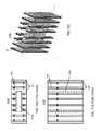
- FIGS. 15A and 15Bdepict an exemplary printed magnetic structure that comprises alternating polarity spaced maxel stripes.
- FIGS. 15C and 15Ddepict an exemplary printed magnetic structure that comprises spaced Barker-4 coded maxel stripes.
- FIG. 16Adepicts an oblique view of an exemplary prior art Halbach array.
- FIG. 16Bdepicts a top down view of the same exemplary Halbach array of FIG. 16A .
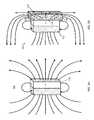
- FIGS. 17A and 17Bdepict side and oblique views of an exemplary hybrid magnet-pole piece structure in accordance with one aspect of the invention.
- FIG. 17Cdepicts a target on top of the exemplary hybrid magnet-pole piece structure of FIGS. 17A and 17B where flux lines are shown moving in a clockwise direction.
- FIG. 17Ddepicts a target on bottom of the exemplary hybrid magnet-pole piece structure of FIGS. 17A and 17B where flux lines are shown moving in a counter-clockwise direction.
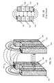
- FIG. 17Edepicts separated complementary three magnet-two pole piece arrays.
- FIG. 17Fdepicts the complementary arrays of FIG. 17E in contact.
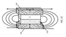
- FIG. 17Gdepicts an exemplary lateral magnet hybrid structure.
- FIG. 17Hdepicts the exemplary lateral magnet hybrid structure of FIG. 17G with a target attached on a first side such that flux lines move in a clockwise manner.
- FIG. 17Idepicts the exemplary lateral magnet hybrid structure of FIG. 17G with a target attached on a second side such that flux lines move in a counter-clockwise manner.
- FIG. 17Jdepicts separated complementary lateral magnet hybrid structures like depicted in FIG. 17G .
- FIG. 17Kdepicts complementary lateral magnet hybrid structures like depicted in FIG. 17G in contact.
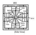
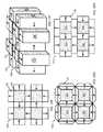
- FIGS. 18A and 18Bdepict a prior art magnet structure where the magnets in the four corners are magnetized vertically and the side magnets between the corner magnets are magnetized horizontally.
- FIGS. 19A and 19Bdepict a four magnet-four pole piece hybrid structure similar to the magnetic structures of FIGS. 18A and 18B where the corner magnets are replaced with pole pieces.
- FIGS. 19C and 19Ddepict lateral magnet hybrid structures that are similar to the hybrid structures of FIGS. 19A and 19B .
- FIG. 19Edepicts a twelve magnet-four pole piece hybrid structure that corresponds to a two-dimensional version of hybrid structure of FIGS. 17A-17F .
- FIG. 19Fdepicts a twelve lateral magnet-four pole piece hybrid structure that corresponds to a two-dimensional version of the lateral magnet hybrid structure of FIGS. 17G-17K .
- FIG. 19Gdepicts use of beveled magnets in a hybrid structure similar to the hybrid structure of FIG. 19E .
- FIG. 19Hdepicts use of different sized magnets in one dimension versus another dimension in a hybrid structure similar to the hybrid structures of FIGS. 19E and 19G .
- FIGS. 19I-19Kdepict movement of the rows of magnets versus the pole pieces and vertical magnets so as to control the flux that is available at the ends of the pole pieces.
- FIGS. 19L and 19Mdepict lateral magnet hybrid structures that are similar to the hybrid structures of FIGS. 19C and 19D except with elongated magnets and pole pieces.
- FIG. 20depicts a prior art magnetic structure that directs flux to the top of the structure.
- FIGS. 21A and 21Bdepict a hybrid structure and a lateral magnet hybrid structure each having a pole piece surrounded by eight magnets in the same magnet pattern as the magnetic structure of FIG. 20 .
- FIG. 22Adepicts an exemplary hybrid rotor in accordance with the invention.
- FIG. 22Bprovides an enlarged segment of the rotor of FIG. 22A .
- FIGS. 22C and 22Ddepict exemplary stator coils.
- FIG. 22Edepicts a first exemplary hybrid rotor and stator coil arrangement.
- FIG. 22Fdepicts a second exemplary hybrid rotor and stator coil arrangement
- FIG. 22Gdepicts a third exemplary hybrid rotor and stator coil arrangement.
- FIG. 22Hdepicts a fourth exemplary hybrid rotor and stator coil arrangement.
- FIG. 22Idepicts an exemplary saddle core type stator-rotor interface.
- FIG. 22Jdepicts a fifth exemplary hybrid rotor and stator coil arrangement.
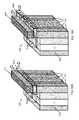
- FIG. 23Adepicts an exemplary metal separator lateral magnet hybrid structure.
- FIG. 23Bdepicts the magnetizations of the magnets of the exemplary metal separator lateral magnet hybrid structure of FIG. 23A .
- FIG. 23Cdepicts an alternative exemplary metal separator lateral magnet hybrid structure having a rounded upper surface.
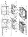
- FIGS. 24A and 24Bdepict assemblies having magnets arranged in accordance with complementary cyclic Barker 4 codes.
- FIG. 24Cdepicts two complementary cyclic lateral magnet assemblies being brought together such that their magnetic structures correlate.
- FIGS. 25A and 25Bdepict cyclic lateral magnet assemblies similar to those of FIGS. 24A-24C except lateral magnets are combined with conventional magnets.
- FIGS. 26A and 26Bdepict exemplary cyclic lateral magnet assemblies similar to those of FIGS. 25A and 25B where the individual conventional magnets are each replaced with four conventional magnets having polarities in accordance with a cyclic Barker 4 code.
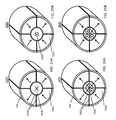
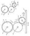
- FIGS. 27A and 27Bdepict an exemplary lateral magnet wheel assembly.
- FIG. 28Adepicts a second exemplary lateral magnet wheel assembly.
- FIG. 28Bdepicts a third exemplary lateral magnet wheel assembly.
- FIG. 28Cdepicts a fourth exemplary lateral magnet wheel assembly having exemplary friction surfaces.
- FIGS. 29A-29Ddepict exemplary use of a guide ring and a slot within a target and optional friction surfaces.
- FIGS. 30A and 30Bdepict exemplary combinations of lateral magnetic wheel assemblies and round targets having different diameters that function as gears.
- FIGS. 31A-31Cdepict top, side, and oblique projection views of an exemplary lateral magnet connector assembly.
- FIGS. 31D-31Fdepict top, side, and oblique projection views of the lateral magnet connector assembly of FIGS. 31A-31C attached to a target also having a connection region.
- FIG. 31Gdepicts the lateral magnetic connector assembly of FIGS. 31A-31C in an attached state with a complementary lateral magnetic connector assembly.
- FIGS. 32A and 32Bdepict top views of two exemplary lateral magnetic connector assemblies having non-magnetic spacers where the magnets are oriented in accordance with a Barker 4 code.
- FIGS. 33A-33Cdepict three exemplary approaches for providing connectors that connect across a connection boundary.
- FIGS. 34A and 34Bdepict exemplary electrical contacts 34 that can be used in an electrical connector.
- FIG. 35Adepicts a top view of an exemplary lateral magnet connector.
- FIG. 35Bdepicts an exemplary striped magnet.
- FIG. 35Cdepicts an oblique view of the exemplary lateral magnet connector assembly of FIG. 35A and a corresponding target.
- FIG. 36Adepicts an alternative view of the exemplary flux concentrator device and target of FIG. 5A .
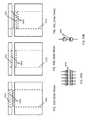
- FIG. 36Bdepicts an exemplary movable magnetic circuit that can be placed between the exemplary flux concentrator device and target shown in FIG. 36A .
- FIG. 36Cdepicts an exemplary movable magnetic circuit in a first location relative to the exemplary flux concentrator device and target of FIG. 36A .
- FIG. 36Ddepicts an exemplary movable magnetic circuit in a second location relative to the exemplary flux concentrator device and target of FIG. 36A .
- FIG. 36Edepicts an alternative view of the exemplary flux concentrator device, exemplary movable magnetic circuit, and target of FIG. 36A .
- FIG. 36Fdepicts an exemplary movable magnetic circuit in a third location relative to the exemplary flux concentrator device and target of FIG. 36A .
- FIG. 37Adepicts an alternative exemplary magnetic circuit that can be placed between the exemplary flux concentrator device and target of FIG. 36A .
- FIG. 37Bdepicts the exemplary magnetic circuit in a first location between the exemplary flux concentrator device and target of FIG. 37A .
- FIG. 38Adepicts a side view of an exemplary flux gap concentrator device configured to produce a high flux density in a gap between two pole pieces.
- FIG. 38Bdepicts a front view of an exemplary pole piece such as is used in the flux gap concentrator device depicted in FIG. 38A .
- FIG. 38Cdepicts a side view of another exemplary flux gap concentrator device configured to produce a high flux density region in a gap between two pole pieces.
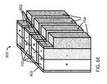
- FIG. 38Ddepicts a side view of an exemplary flux gap concentrator device configured to produce a high flux density in a gap between four pole pieces.
- FIG. 39Adepicts an exemplary flux gap de-concentrator device.
- FIG. 39Bdepicts another exemplary flux de-concentrator device.
- FIG. 39Cdepicts yet another exemplary flux de-concentrator device.
- FIG. 40depicts an exemplary flux concentrator device based on a Halbach magnet array.
- FIG. 41Adepicts another exemplary flux gap concentrator device based on a Halbach magnet array.
- FIG. 41Bdepicts an exemplary flux gap concentrator device that is similar to the flux concentrator device of FIG. 40 except the funnel shaped pole pieces and have been replaced with elbow shaped pole pieces.
- FIG. 42Adepicts an exemplary coil subassembly.
- FIG. 42Bdepicts an exemplary rotor assembly.
- FIG. 42Cdepicts an exemplary flux gap concentrator device.
- Certain described embodimentsmay relate, by way of example but not limitation, to systems and/or apparatuses comprising magnetic structures, magnetic and non-magnetic materials, methods for using magnetic structures, magnetic structures having magnetic elements produced via magnetic printing, magnetic structures comprising arrays of discrete magnetic elements, combinations thereof, and so forth.
- Example realizations for such embodimentsmay be facilitated, at least in part, by the use of an emerging, revolutionary technology that may be termed correlated magnetics.
- This revolutionary technology referred to herein as correlated magneticswas first fully described and enabled in the co-assigned U.S. Pat. No. 7,800,471 issued on Sep. 21, 2010, and entitled “A Field Emission System and Method”. The contents of this document are hereby incorporated herein by reference.
- a second generation of a correlated magnetic technologyis described and enabled in the co-assigned U.S. Pat. No. 7,868,721 issued on Jan. 11, 2011, and entitled “A Field Emission System and Method”. The contents of this document are hereby incorporated herein by reference.
- a third generation of a correlated magnetic technologyis described and enabled in the co-assigned U.S. Pat. No. 8,179,219 issued on May 15, 2012, and entitled “A Field Emission System and Method”. The contents of this document are hereby incorporated herein by reference.
- Another technology known as correlated inductance, which is related to correlated magneticshas been described and enabled in the co-assigned U.S. Pat. No. 8,115,581 issued on Feb. 14, 2012, and entitled “A System and Method for Producing an Electric Pulse”. The contents of this document are hereby incorporated by reference.
- Material presented hereinmay relate to and/or be implemented in conjunction with multilevel correlated magnetic systems and methods for producing a multilevel correlated magnetic system such as described in U.S. Pat. No. 7,982,568 issued Jul. 19, 2011 which is all incorporated herein by reference in its entirety. Material presented herein may relate to and/or be implemented in conjunction with energy generation systems and methods such as described in U.S. Pat. No. 8,222,986 issued on Jul. 17, 2012, which is all incorporated herein by reference in its entirety. Such systems and methods described in U.S. Pat. No. 7,681,256 issued Mar. 23, 2010, U.S. Pat. No. 7,750,781 issued Jul. 6, 2010, U.S. Pat. No. 7,755,462 issued Jul. 13, 2010, U.S. Pat. No.
- Material presented hereinmay relate to and/or be implemented in conjunction with systems and methods described in U.S. Provisional Patent Application 61/640,979, filed May 1, 2012 titled “System for Detaching a Magnetic Structure from a Ferromagnetic Material”, which is incorporated herein by reference. Material may also relate to systems and methods described in U.S. Provisional Patent Application 61/796,253, filed Nov. 5 2012 titled “System for Controlling Magnetic Flux of a Multi-pole Magnetic Structure”, which is incorporated herein by reference. Material may also relate to systems and methods described in U.S. Provisional Patent Application 61/735,460 filed Dec. 10, 2012 titled “An Intelligent Magnetic System”, which is incorporated herein by reference.
- the present inventionrelates to a system for concentrating magnetic flux of a multi-pole magnetic structure having rectangular or striped polarity regions having either a positive or negative polarity that are separated by non-magnetic regions, where the polarity regions may have an alternating polarity pattern or have a polarity pattern in accordance with a code, where herein an alternating polarity pattern corresponds to polarity regions having substantially the same size such that produced magnetic fields alternate in polarity substantially uniformly.
- a coded polarity patternmay comprise adjacent regions having the same polarity (e.g., two North polarity stripes separated by a non-magnetized region) and adjacent regions having opposite polarity or may comprise alternating polarity regions that have different sizes (e.g., a North polarity region of width 2 X next to a South polarity region of width X).
- coded magnetic structureshave at least three code elements and produce peak forces when aligned with a complementary coded magnetic structure but have forces that substantially cancel when such structures are misaligned, whereas complementary (uniformly) alternating polarity magnetic structures produce either all attract forces or all repel forces when their respective magnetic regions are in various alignments.
- coded magnetic structures based on Barker 4 codesare provided herein but one skilled in the art will understand that other Barker codes and other types of codes can be employed such as those described in the patents referenced above.
- polarity regionscan be separated magnets or can be printed magnetic regions on a single piece of magnetizable material. Such printed regions can be stripes made up of groups of printed maxels such as described in patents referenced above.
- Pole piecesare magnetically attached to the magnets or (maxel stripes) using a magnet-to-pole piece interface with a first area.
- the pole piecescan then be attached to a target such as a piece of ferromagnetic material or to complementary pole pieces using a pole piece-to-target interface that has a second area substantially smaller than the first area.
- the targetmay be a gap between pole piece-to-target interfaces of two or more pole pieces.
- the primary object of this inventionis to produce a surface that when taken as a whole achieves a substantial increase in total flux and therefore force density when in proximity to a ferromagnetic material or another magnet.
- a maximum force density or maximum force produced over an areais achieved when the cross section of the pole pieces where they interface with the working surface of a target are just in saturation when in a closed magnetic circuit, where the maximum force density is not achieved when the cross section of the pole pieces where they interface with the working surface of a target is over or under saturated.
- the magnetic material that sources the fluxbe as thin as possible but still provide magnetic flux at the saturation flux density of the magnetic material since a larger cross sectional area would act to dilute the force density since no flux emerges from its area, where under one arrangement, the magnetic material is thinner than the pole pieces used to concentrate the flux.
- This ‘flux concentration’ techniquerelies on the fact that the saturation flux density of known magnetic materials is substantially lower than the saturation flux density of materials such as low carbon steel or iron, where a saturation flux density corresponds to the maximum amount of flux that can be achieved for a given unit of area. Using this technique, force densities of four or more times the density of the strongest magnetic materials are possible.
- the multiplication factorcan be twenty or more permitting very strong magnetic structures to be constructed very inexpensively.
- flux concentrationWhen flux is routed at right angles to a working surface from a magnetic surface this ‘flux concentration’ technique can be referred to as a ‘lateral magnet’ technique.
- FIG. 1Adepicts an exemplary magnet field 100 of a magnet 102 , where the magnetic flux lines pass from the South ( ⁇ ) pole to the North (+) pole and then wrap around the magnet to the South pole in a symmetrical manner.
- a rectangular pole piece 104 having sufficient ferromagnetic material to achieve saturationis placed onto one side of the magnet 102 as shown in FIG. 1B , the magnetic flux passing from the South pole to the North pole is redirected substantially perpendicular to the magnet 102 by the pole piece 104 such that it exits the top and bottom of the pole piece 104 and again wraps around to the South pole of the magnet 102 .
- the pole piece 104contacts the magnet 102 using a magnet-to-pole piece interface 106 that is substantially larger than the area of the ends 108 of the pole piece 104 from which the magnetic flux is shown exiting the pole piece 104 .
- FIG. 1Cdepicts a magnet 102 having two such rectangularpole pieces 104 , where there is a pole piece 104 on each side of the magnet 102 . As shown the flux is shown being primarily above and below the magnet 102 such that it's attachment interface has been fully rotated 90°.
- FIGS. 2A and 2Bdepict portions of exemplary magnetic fields 100 between two adjacent magnets 102 having an opposite polarity relationship, where each magnet 102 has a pole piece 104 on one side.
- FIGS. 3A and 3Bdepict portions of exemplary magnetic fields 100 between two adjacent magnets 102 having an opposite polarity relationship, where each magnet 102 has pole pieces 104 on both sides of the magnet 102 . Exemplary magnetic fields between the bottom of the pole pieces 104 and the magnets 102 , and between the bottoms of the pole pieces 104 are not shown in FIG. 3A .
- FIG. 4Adepicts an exemplary magnetic structure 400 comprising two spaced magnets 102 having an opposite (or alternating) polarity relationship attached by a shunt plate 402 and attached to a target 404 such as a piece of iron.
- FIG. 4Bdepicts an exemplary magnetic flux circuit created by the shunt plate 402 and the target 404 as indicated by the dotted oval shape.
- the spacing between magnets 102can be air or it can be any form of non-magnetic material such as plastic, Aluminum, or the like.
- FIG. 4Cdepicts an exemplary magnetic structure 406 comprising four magnets 102 having an alternating polarity relationship having a shunt plate 402 and attached to a target 404 such that three magnetic flux circuits are created.
- FIG. 4Ddepicts an oblique projection of the magnetic structure 406 of FIG. 4C approaching the target 404 , where the target interface area 408 of each magnet 102 has an area equal to the magnet's height (h) multiplied by the magnet's width (d 1 ).
- FIG. 5Adepicts an exemplary flux concentrator device 500 in accordance with one embodiment of the present invention, which corresponds to the magnetic structure and shunt plate of FIG. 4C with four rectangular pole pieces 104 that each have magnet-to-pole piece interface 502 that interface fully with the target interface surfaces 408 of each of the four magnets 102 of the magnetic structure.
- the pole pieces 104are each shown to have a pole piece-to-target interface 504 having an area equal to each pole piece's width (d 1 ) to the pole piece's thickness (d 2 ), where each pole piece width may be equal to the width of the magnet 102 to which it is attached.
- a flux concentrator device 500may include a magnetic structure comprising a plurality of discrete magnets separated by spacings or may include a printed magnetic structure with maxel stripes separated by spacings (i.e., non-magnetized regions or stripes) and pole pieces 104 that interface with the discrete magnets 102 or the maxel stripes. Maxel stripes are depicted in FIGS. 15A-15D .
- the pole piecesmay extend at least the height of the magnet structure (or beyond) with the purpose of directing flux 90 degrees thereby achieving a greater (pounds force per square inch) psi at the top and/or bottom of the pole pieces 104 than can be achieved at the sides of the magnets 102 to which they are interfacing.
- Optional shunt plates 402are shown on the sides of the magnets 102 opposite the pole pieces 104 .
- FIG. 5Bdepicts an exemplary magnetic flux circuit 506 , where on one side of the magnets 102 the circuit is made using a shunt plate 402 and on the other side of the magnets 102 the circuit is made using two pole pieces 104 attached to a target 404 that spans the two pole pieces 102 .
- FIG. 5Cdepicts the exemplary flux concentrator device 500 of FIG. 5A that has been attached to a target 404 that spans the four pole pieces 104 of the device 500 .
- FIG. 5Cdepicts the three magnetic flux circuits resulting from the use of the shunt plate 402 , the pole pieces 104 , and the target 404 with the magnets 102 .
- FIG. 6Ashows an exemplary flux concentrator device 500 similar to the device 500 of FIG. 5A except the pole pieces 104 extend both above and below the magnetic structure made up of magnets 102 .
- the pole pieces 104are the full length of the magnets 102 making up the magnetic structure but do not otherwise extend above or below the magnetic structure.
- the pole pieces 104are shorter than the magnets 102 of the magnetic structure where it is intended that the target 404 (not shown) interface with both the magnets 102 and the pole pieces 104 .
- the pole pieces 104are configured to accept targets 404 bottom that interface with the magnets 102 and the pole pieces 104 at the top of the device pole pieces 104 .
- FIG. 6Edepicts additional pole pieces 602 having been added to the upper portions of the magnets 102 in the device 500 of FIG. 6C in order to provide protection to the surfaces of the magnets 102 .
- FIGS. 7A-7Edepict various exemplary flux concentrator devices 700 having pole pieces on both sides of the magnetic structures.
- FIG. 7Adepicts a magnetic structure comprising four alternating polarity magnets 102 , which could be four alternating polarity maxel stripes (i.e., a printed magnetic structure), sandwiched between pole pieces 104 that extend from the bottom of the magnets 102 and then slightly above the magnets 102 .
- FIG. 7Bdepicts pole pieces 104 that extend both above and below the magnets 102 .
- FIG. 7Cdepicts pole pieces 104 that are the same height and are attached flush with the magnets 102 .
- FIG. 7Adepicts a magnetic structure comprising four alternating polarity magnets 102 , which could be four alternating polarity maxel stripes (i.e., a printed magnetic structure), sandwiched between pole pieces 104 that extend from the bottom of the magnets 102 and then slightly above the magnets 102 .
- FIG. 7Bdepicts pole pieces
- FIG. 7Ddepict pole pieces 104 that are shorter than the magnets 102 for receiving a target 404 (not shown) having a corresponding shape (e.g., an elongated C or U shape) or two bar shaped targets 404 .
- FIG. 7Edepicts pole pieces 104 configured for receiving two targets 404 having a corresponding shape or four bar shaped targets 404 .
- FIG. 8Adepicts an exemplary flux concentrating device 800 comprising three magnetic structures like those of FIG. 7A except the magnets 102 in the middle structure are each rotated 180° compared to the magnets 102 in the two outer most structures. Because the eight pole pieces 104 in the inside of the device 800 are receiving twice the flux as the eight pole pieces 104 on the outside of the device 800 , those pole pieces on the outside are reduced by half such that their PSI is substantially the same as those inside the device 800 .
- FIG. 8Bdepicts an exemplary flux concentrating device 800 like that of FIG. 8A except the pole pieces 104 in the inside of the device are configured to accept targets 404 (not shown) that recess into the device 800 . Such recessing into the device 800 provides a male-female type connection that can provide mechanical strength in addition to magnetic forces.
- FIGS. 9A-9GThe concept of male-female type interfaces is further depicted in FIGS. 9A-9G where various shapes are shown, where one skilled in the art will recognize that all sorts of interfaces are possible other than flat interfaces between pole pieces 104 of flux concentrator devices 500 / 700 / 800 and targets 404 , which may be pole pieces 104 of another flux concentrator device 500 / 700 / 800 .
- FIG. 10Adepicts an exemplary flux concentrator device 1000 like that shown previously in FIG. 5A , where the magnetic structure comprises four spaced magnets 102 (or maxel stripes) having a polarity pattern in accordance with a Barker 4 code.
- FIG. 10Bdepicts another exemplary flux concentrator device 1000 like that of FIG. 10A , where the magnets 102 of the magnetic structure have a polarity pattern that is complementary to the magnets 102 of the magnetic structure of FIG. 10A .
- either of the flux concentrator devices 800 of FIGS. 10A and 10Bcan be turned upside down where the pole pieces 104 of one of the flux concentrator devices 800 is attached to the pole pieces 104 of the other flux concentrator device 800 in accordance with the Barker 4 correlation function.
- FIGS. 11A and 11Bdepict complementary Barker-4 coded flux concentrator devices 1100 that like those of FIGS. 10A and 10B that can be turned upside down and aligned with the other device 1100 so as to produce a peak attractive force. It should be noted that if either structure is placed on top of a duplicate of itself that a peak repel force can be produced, which is effectively inverting the correlation function of the Barker 4 code.
- FIG. 12depicts four Barker-4 coded flux concentrator devices 1000 oriented in an array where they are spaced apart that produce a Barker-4 by Barker-4 coded composite flux concentrator device 1200 .
- FIGS. 13A and 13Bdepict two variations of self-complementary Barker4-2 coded flux concentrator devices 1300 , where each device can be placed on top of a duplicate device 1300 and aligned to produce a peak attract force and where the devices will align in the direction perpendicular to the code because each Barker-4 code element is represented by a ‘+ ⁇ ’ or ‘ ⁇ +’ symbol implemented perpendicular to the code.
- FIG. 14depicts exemplary tapered pole pieces 104 .
- the pole pieces 104are tapered such that they are thinner at the bottom of the magnets 102 and grow thicker and thicker towards the pole piece-to-target interface 504 . By tapering the pole pieces 104 , there can be less flux leakage between adjacent pole pieces 104 .
- FIGS. 15A and 15Bdepict and exemplary printed magnetic structure 1500 that comprises alternating polarity spaced maxel stripes 1502 1504 , where each of the overlapping circles represents a printed positive polarity maxel 1506 or negative polarity maxel 1508 .
- FIGS. 15C and 15Ddepicts an exemplary printed magnetic structure 1510 comprising spaced maxel stripes 1502 1504 having a polarity pattern in accordance with a Barker 4 pattern.
- a magnetic structureis movable relative to one or more pole pieces enabling force at a pole piece-to-target interface to be turned on, turned off, or controlled between some minimum and maximum value.
- the magnetic structuremay be tilted relative to pole pieces or may be moved such that the pole pieces span between opposite polarity magnets (or stripes) so as to substantially prevent the magnetic flux from being provided to the pole piece-to-target interface.
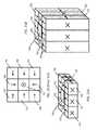
- FIG. 16Adepicts an oblique view of an exemplary prior art Halbach array 1600 constructed of five discreet magnets 102 having magnetization directions in accordance with the directions of the arrows, where X represents the back end (or tail) of an arrow and the circle with a dot in the middle represents the front end (or tip) of an arrow. Such an array causes the magnetic flux to be concentrated beneath the structure as shown.
- FIG. 16Bdepicts a top down view of the same exemplary Halbach array 1600 of FIG. 16A .
- FIGS. 17A and 17Bdepict side and oblique views of an exemplary hybrid magnet-pole piece structure 1700 in accordance with one aspect of the invention.
- the hybrid magnet-pole piece structure 1700comprises three magnets 102 sandwiching two pole pieces 104 , where the magnets 104 have a polarity arrangement like those of the first, third, and fifth magnets of the Halbach array 1600 of FIGS. 16A and 16B .
- the magnetic behaviorhowever, is substantially different. With the Halbach array of magnets 102 , the field is always concentrated on one side of the magnetic structure 1600 .
- hybrid magnet-pole piece structure (or hybrid structure) 1700when a target material 404 such as a ferromagnetic material is not present to complete a circuit between the two pole pieces 104 , the opposite polarity fields emitted by the pole pieces are emitted on all sides of the poles substantially equally. But, when a target material 404 is placed on any of the four sides of the hybrid structure, a magnetic circuit is closed, where the direction of the fields through the pole pieces depends on which side the target 404 is placed. For example, in FIG. 17C the flux lines are shown moving in a clockwise direction, whereas in FIG.
- the flux linesare shown moving in a clockwise direction, where the flux through the magnet 102 and target 404 is the same in both instances but the flux direction through the poles 104 is reversed.
- the targetscould be placed on the front or back of the hybrid structure 1700 and the flux lines going through the pole pieces 104 would rotate plus or minus ninety degrees.
- two complementary hybrid structures 1700can be near each other but separated and they will not substantially react magnetically until the pole pieces 104 of the hybrid structures 1700 are substantially close or they come in contact at which time a circuit is completed between them and the flux is concentrated at the ends of the contacting pole pieces 104 .
- FIG. 17Gdepicts a lateral magnet hybrid structure 1702 where without a target 404 the fields emitted at the ends of the poles pieces 104 are substantially the same and are not concentrated.
- the flux direction through the pole pieces 104depends on which ends of the pole pieces 104 that the target 404 is placed.
- the fluxis shown moving in a clockwise manner but in FIG. 17I , the flux is shown moving in a counter-clockwise direction.
- two complementary lateral magnet hybrid structures 1702can be near each other but separated and they will not substantially react magnetically until the pole pieces 104 of the hybrid structures 1702 are substantially close or they come in contact at which time a circuit is completed between them and the flux is concentrated at the ends of the contacting pole pieces 104 .
- FIGS. 18A and 18Bdepict a prior art magnet structure 1800 where the magnets in the four corners are magnetized vertically and the side magnets between the corner magnets are magnetized horizontally.
- the side magnetsare oriented such that flux moves towards the corner magnets where the flux is moving downwards and away from the corner magnets where the flux is moving upwards. The resulting effect is that flux is always concentrated beneath the structure.
- FIGS. 19A and 19Bdepict a four magnet-four pole piece hybrid structure 1900 similar to the magnetic structures 1800 of FIGS. 18A and 18B where the corner magnets 102 are replaced with pole pieces 104 .
- the pole pieces 104 of the hybrid structure 1900 of FIGS. 19A and 19Bwill emit opposite polarity fields on all sides of the poles substantially equally.
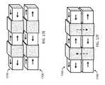
- FIGS. 19C and 19Ddepict lateral magnet hybrid structures 1902 that are similar to the hybrid structures 1900 of FIGS. 19A and 19B .
- FIG. 19Edepicts a twelve magnet-four pole piece hybrid structure 1904 that corresponds to a two-dimensional version of the hybrid structure 1700 of FIGS. 17A-17F .
- FIG. 19Fdepicts a twelve lateral magnet-four pole piece hybrid structure 1906 that corresponds to a two-dimensional version of the lateral magnet hybrid structure 1702 of FIGS. 17G-17K .
- FIG. 19Gdepicts use of beveled magnets 102 in a hybrid structure 1908 similar to the hybrid structure 1904 of FIG. 19E .
- FIG. 19Hdepicts use of different sized magnets 102 in one dimension versus another dimension in a hybrid structure 1910 similar to the hybrid structures 1904 1908 of FIGS. 19E and 19G .
- FIGS. 19I-19Kdepict movement of the rows of magnets versus the pole pieces 104 and vertical magnets 102 so as to control the flux that is available at the ends of the pole pieces 104 .
- FIG. 20depicts a prior art magnetic structure that directs flux to the top of the structure.
- FIGS. 21A and 21Bdepict a hybrid structure and a lateral magnet hybrid structure each having a pole piece surrounded by eight magnets in the same magnet pattern as the magnetic structure of FIG. 20 , where the direction of the flux through the pole piece will depend on which end a target is placed.
- FIG. 22Adepicts an exemplary hybrid rotor 2200 in accordance with the invention where lateral magnets 102 on either side of pole pieces 104 alternate such that their magnetization is as depicted with the arrows shown.
- FIG. 22Bprovides an enlarged segment 2202 of the rotor 2200 .
- Stator coils 2204 having cores 2206such as depicted in FIGS. 22C and 22D would be placed on a corresponding stator (not shown), where there could be a one-to-one relationship between the number of stator coils 2204 and pole pieces 104 on a rotor 2200 or there could be less stator coils 2204 by some desired ratio of stator coils 2204 to pole pieces 104 .
- each stator coil 2204The pole pieces 104 and the cores 2206 of each stator coil 2204 are configured such that flux from the pole piece 104 can traverse a small gap between a given pole piece 104 and a given core 2206 of a given stator coil 2204 .
- this arrangementcorresponds to a pole piece 104 to stator coil 2204 interface that can be used to enable motors, generators, actuators, and the like based on the use of lateral magnet arrangements.
- FIG. 22Edepicts an exemplary hybrid rotor and stator coil arrangement 2210 where the cores 2206 of paired stator coils 2204 have shunts plates 402 that join the cores 2206 .
- FIG. 22Fdepicts an exemplary hybrid rotor and stator coil arrangement 2212 where the cores 2206 of paired stator coils 2204 are all joined by a single shunt plate 402 .
- FIG. 22Gdepicts an exemplary hybrid rotor and stator coil arrangement 2214 where two stator coils 2204 are used with one rotor where the cores 2206 of the paired stator coils 2204 have shunts plates 402 that join the cores 2206 .
- the material making up the pole pieces 104can be made thinner.
- FIG. 22Hdepicts an exemplary hybrid rotor and stator coil arrangement 2216 where two stator coils 2204 are used with one rotor 2200 where the cores 2206 of the paired stator coils 2204 are all joined by a single shunt plate 402 .
- FIG. 22Idepicts an exemplary saddle core type stator-rotor interface 2220 where core material 2206 wraps around from one side of the pole piece 104 to the other side providing a complete circuit.
- a coil 2204can be placed around the core material 2206 anywhere along the core material 2206 to include the entire core material 2206 .
- This saddle core arrangementis similar to that described in U.S. Non-provisional patent application Ser. No. 13/236,413, filed Sep. 19, 2011, titled “An Electromagnetic Structure Having A Core Element That Extends Magnetic Coupling Around Opposing Surfaces Of A Circular Magnetic Structure”, which is incorporated by reference herein.
- FIG. 22Jdepicts an exemplary hybrid rotor and stator coil arrangement 2222 involving two rotors 2200 that are either side of a stator coil array where the opposing pole pieces of the two rotors have opposite polarities.
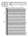
- FIG. 23Adepicts an exemplary metal separator lateral magnet hybrid structure 2300 comprising long pole pieces 104 sandwiched between magnets 102 having magnetizations as shown in FIG. 23B .
- a target 404 placed on topcan be used to separate metal from material striking it. Under one arrangement the pole pieces 104 and the target would be shaped to provide a rounded upper surface.
- Cyclic lateral magnet assembliescan be arranged to correspond to cyclic codes.
- the two complementary cyclic lateral magnet assemblies 2400can be brought together such that their magnetic structures correlate. Either assembly 2400 can then be turned to de-correlate the magnetic structures.
- a sleeve 2404is shown that can be used to constrain the relative movement of the two assemblies 2400 relative to each other to rotational movement while allowing the two assemblies 2400 to be brought together or pulled apart.
- FIGS. 25A and 25Bdepict cyclic lateral magnet assemblies 2500 similar to those of FIGS. 24A-24C except lateral magnets around the perimeter 102 a / 104 are combined with conventional magnets 102 b in the center.
- the opposite polarity magnets 102 b in the center of the assemblies 2500which will have a farther reach than the lateral magnets 102 a / 104 , begin to attract each other so to bring the two assemblies 2500 together and, once together, either lateral magnet assembly 2500 can be rotated relative to the other to achieve a correlated peak attract force position.
- Barker 4 codealso requires physical constraint of the two assemblies 2500 so that they can only rotate relative to each other such that the two ends of the assemblies 2500 are always fully facing each other.
- Various types of mechanismscan be employed such as an outer cylinder or sleeve 2404 that would provide for a male-female connector type attachment.
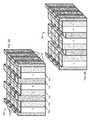
- FIGS. 26A and 26Bdepict exemplary cyclic lateral magnet assemblies 2600 similar to those of FIGS. 25A and 25B where the individual conventional magnets 102 b are each replaced with four conventional magnets 102 b having polarities in accordance with a cyclic Barker 4 code.
- the conventional magnets 102 b of FIGS. 25A and 25Bwould provide an attract force regardless of rotational alignment
- the conventional magnets 102 b of FIGS. 26A and 26Bhave a correlation function where there is a peak attract force and substantially zero off peak forces.
- FIGS. 27A and 27Bdepict an exemplary lateral magnet wheel assembly 2700 comprising a ring magnet 102 and a ring-shaped pole piece 104 .
- An axle 2702can be placed inside the holes 2704 of the lateral magnet wheel assembly 2700 such that the axle 2702 is fixed relative to the lateral magnet wheel assembly 2700 or the assembly 2700 is free to turn relative to the axle 2702 .
- a motor or other mechanism used to rotate the axle 2702thereby causes the wheel assembly 2700 to rotate.
- flux from the magnet 102is directed through the pole piece 104 to the target 404 .
- FIG. 28Adepicts an exemplary lateral magnet wheel assembly 2800 comprising a ring magnet 102 and two pole pieces 104 , where there is a pole piece 104 on each side of the magnet 102 .
- flux from the magnet 102is directed through the two pole pieces 104 to the target 404 .
- given pole pieces 104are on both sides of the magnet 102 , a magnetic circuit is created from one pole piece 104 to the target 404 to the other pole piece 104 and through one pole piece 104 through the magnet 102 to the other pole piece 104 .
- FIG. 28Bdepicts an exemplary lateral magnet wheel assembly 2802 comprising three ring magnets 102 interleaved between four pole pieces 104 , where the ring magnets 102 are in an alternating polarity arrangement.
- the wheel assembly 2802is placed in contact with a target 404 a plurality of magnetic circuits are created with the target 404 .
- FIG. 28Cdepicts use of friction surfaces 2804 as part of a lateral magnet wheel assembly 2806 to provide a griping force between the wheel assembly 2806 and a target 404 .
- FIGS. 29A-29Ddepict use of a guide ring 2902 and a slot 2904 within a target 404 and optional friction surfaces 2804 , where the guide ring 2902 and slot 2904 can enable applications such as toy race cars and tracks as well as enable tracked robotic wheels and the like.
- FIGS. 30A and 30Bdepict combinations of lateral magnetic wheel assemblies 3000 a 3000 b and round targets 404 having different diameters that function as gears.
- the lateral magnet wheel assembly 3000 a having the smallest diameteris free to rotate relative to a free axle 3002 whereby the rotational force of the fixed axle 3004 driving the lateral magnet wheel assembly 3000 b having the largest diameter is converted to turn the smaller wheel assembly 3002 a .
- both lateral wheel assemblies 3000 a 3000 bcould have fixed axles 3004 such that the various diameters of the wheels determine the ratio of turning rates between the axles 3004 fixed to the two lateral magnetic wheel assemblies 3000 a 3000 b.
- FIGS. 31A-31Cdepict top, side, and oblique projection views of an exemplary lateral magnet connector assembly 3100 comprising magnets 102 and pole pieces 104 and a connection region 3102 within which some form of connection such as an electrical connection, hydraulics connection, optical connection, or some other form of connection can be made when a lateral magnet connector assembly 3100 is attached to a target 404 or to another lateral magnet connector assembly 3100 .
- a plurality of magnets 102 having opposite polarity magnetizationare interleaved between pole pieces 104 to form a connector assembly 3100 having a connection region 3102 .
- the connection region 3102is shown being in a central portion of the assembly 3100 and is shown passing the full height of the assembly 3100 . But, the connection region 3102 can have any depth desired and can be located at any desired location other than a central location.
- FIGS. 31D-31Fshow top, side, and oblique projection views of the lateral magnet connector assembly 3100 of FIGS. 31A-31C attached to a target 404 also having a connection region 3102 .
- the lateral magnet connector assembly 3100when attached to the target 404 their respective connection regions 3102 become aligned whereby connectors in such connection regions 3102 can be configured to connect.
- FIG. 31Gdepicts the lateral magnetic connector assembly 3100 of FIGS. 31A-31C in an attached state with a complementary lateral magnetic connector assembly 3100 ′, which corresponds to a duplicate of assembly 3100 that has been rotated 180°.
- FIGS. 32A and 32Bdepict top views of two exemplary lateral magnetic connector assemblies 3200 a 3200 b having non-magnetic spacers 2402 where the magnets 102 are oriented in accordance with a Barker 4 code.
- a Barker 4 codeOne skilled in the art of coding will recognize that the complementary Barker 4 patterns are implemented with lateral magnet subassemblies 3202 3204 comprising magnets 102 having complementary orientations, whereby complementary lateral magnet subassemblies 3202 3204 are the ‘symbols’ used to implement the complementary Barker 4 codes.
- one dimensional codessuch as Barker codes can also be implemented in a cyclic manner.
- the magnets 102 b in the centers of the lateral magnet assemblies 2500 of FIGS. 25A and 25Bcould be removed providing for connection regions 3102 in which connectors could be used whereby there is one rotational alignment that would achieve attachment and a desired connection.
- FIGS. 33A-33Cdepict three basic approaches for providing connectors 3302 that connect across a connection boundary 3304 when the two connection regions 3102 of a lateral magnetic connector assembly 3100 and a target 404 (or another lateral magnetic connector assembly 3100 ) are aligned and magnetically attached.
- connectors 3302can be configured in a male/female type connection configuration such as shown in FIGS. 33A and 33C or in a flush type connection such as shown in FIG. 33B .
- FIGS. 34A and 34Bdepict exemplary electrical contacts 3402 , 3404 that can be used in an electrical connector.
- electrical contacts 3402such as used in the Apple® Magsafe® power cord are depicted.
- FIG. 34Ba male/female type pin connector 3404 is depicted.
- all sorts of electrical, fluid, optical, or other types of connectorscan be used with the invention.
- FIG. 35Adepicts a top view of another exemplary lateral magnet connector assembly 3500 comprising four striped magnets 3502 , four dipole magnets 102 , and ten pole pieces 104 for providing magnetic attachment about a connection region 3102 , where the magnetization of the striped magnets 3502 and dipole magnets 102 is indicated by arrows.
- FIG. 35Bdepicts an exemplary striped magnet 3502 where a left portion has a first polarity ‘ ⁇ ’ and a right portion has a second polarity ‘+’ opposite the first polarity, where there is a transition region 3504 where the two polarities transition.
- a transition region 3504where the two polarities transition.
- transition profilesare possible including polarity transition regions where there is zero field portion that is a line instead of a point.
- FIG. 35Cdepicts an oblique view of the exemplary lateral magnet connector assembly 3500 of FIG. 35A and a corresponding target 404 .
- FIG. 36Adepicts an alternative view of the exemplary flux concentrator device 500 and target of FIG. 5A .
- FIG. 36Adepicts the exemplary flux concentrator device 500 of FIG. 5A that has been attached to a target 404 that spans the four pole pieces 104 of the device 500 , where a shunt plate 402 is also attached to the pole pieces 104 .
- FIG. 36Bdepicts an exemplary movable magnetic circuit 3602 that can be placed between the exemplary flux concentrator device 500 and target 404 shown in FIG. 36A .
- the movable magnetic circuit 3602comprises a piece of non-magnetically active material, for example, a clear polycarbonate material having four pole pieces 104 ′.
- non-magnetically active materialssuch as aluminum, stainless steel, wood, plastic, or the like could be used. Such materials could be polished, lubricated, or mechanically configured to enable easy movement, which might be constrained in some manner, for example, the movable magnetic circuit could be constrained such that only sideways movement is allowed.
- the thickness of the pole pieces 104 ′can be selected to meet magnetic circuit requirements.
- FIG. 36Cdepicts the exemplary movable magnetic circuit 3602 in a first location relative to the exemplary flux concentrator device 500 and target 404 of FIG. 36A .
- the pole pieces 104 ′ of the movable magnetic circuit 3602substantially align with the pole pieces 104 of the flux concentrator device 500 , whereby a substantial amount of the flux concentrated at the pole piece-to-target interfaces of the pole pieces 104 of the flux concentrator device 500 is directed through the corresponding pole pieces 104 ′ of the movable magnetic circuit into the target 404 .
- FIG. 36Ddepicts the exemplary movable magnetic circuit 3602 in a second location relative to the exemplary flux concentrator device 500 and target 404 of FIG. 36A .
- the movable magnetic circuit 3602is located relative the exemplary flux concentrator device 500 such that the three right-most pole pieces 104 ′ of the moveable magnetic circuit 3602 interface with portions of adjacent pole pieces 104 of the exemplary flux concentrator device 500 .
- the movable magnetic circuit 3602provides direct magnetic circuits between its pole pieces 104 ′ and the pole pieces 104 of the flux concentrator device 500 such that much of the flux that would otherwise be directed into the target if the flux concentrator 500 were directly in contact with the target 404 is not directed and instead is contained within the flux concentrator 500 and movable magnetic circuit 3602 .
- the relative location of the movable magnetic circuit 3602 relative to the flux concentrator 500determines the amount of flux directed into the target 404 , where the amount of flux can be varied from some maximum amount to some minimum amount.
- the arrows shown in FIGS. 36C and 36Dare intended to denote that the movement of the movable magnetic circuit 3602 is constrained to sideways movement only.
- FIG. 36Edepicts an alternative view of the exemplary flux concentrator device 500 , exemplary movable magnetic circuit 3602 , and target 404 of FIG. 36A , where the arrows are intended to indicate that the movement of the movable magnetic circuit 3602 is constrained to sideways and backward and forward movements.
- FIG. 36Fdepicts an exemplary movable magnetic circuit in a third location relative to the exemplary flux concentrator device and target of FIG. 36A .
- the movable magnetic circuithas been moved backward and sideways such that the amount of flux directed into the target 404 is less than when the movable magnetic circuit is in the location shown in FIG. 36E where the corresponding pole pieces 104 104 ′ align.
- the pole pieces 104 ′ of the movable magnetic circuitcan be located relative to the pole pieces of the flux concentrator device 104 such that direct magnetic circuits between pole pieces 104 are produced or not produced.
- the minimum cross-sectional areas of each of the pole pieces 104 ′ of the movable magnetic circuit 3602determine the amount of flux directed into the target 404 , whereby as a given minimum cross-sectional area is restricted, the corresponding magnetic circuit provided to the target 404 is also restricted due to the pole piece 104 ′ of the movable magnetic circuit 3602 becoming saturated.
- FIG. 37Adepicts an exemplary magnetic circuit 3702 that can be placed between the exemplary flux concentrator device 500 and target 400 of FIG. 36A .
- each pole piece 104 ′ of the magnetic circuit 3702has a first interface at the bottom of each pole piece 104 ′ that is intended to be substantially the same as the pole piece-to-target interface of each pole piece 104 of the flux concentrator device 500
- each pole piece 104 ′ of the magnetic circuit 3702has a second interface at the top of each pole piece 104 ′ having a rectangular shape.
- the pole pieces 104 ′ of the magnetic circuit 3702serve to change the ‘footprint’ available for a target 404 , where the target 404 of FIG. 37A has a substantially square bottom surface and the target of FIG. 36A has a substantially rectangular bottom surface.
- FIG. 37Bdepicts the exemplary magnetic circuit in a first location between the exemplary flux concentrator device and target of FIG. 37A .
- magnetic circuit 3702may be movable or may be configured to remain in a fixed location relative to the flux concentrator device, where the interfacing to the respective pole pieces 104 104 ′ determines the flux directed to the target 404 .
- the target 404 of FIGS. 36A-36E and FIGS. 37A and 37Bcould instead be another flux concentrator device.
- Lateral magnet assemblies as described hereincan be used for attachment of any two objects such as electronics devices to walls or vehicle dashes.
- any two objectssuch as electronics devices to walls or vehicle dashes.
- the present inventionenables a small external attachment point to be provided.
- One such applicationcould involve a screw-like lateral magnet device that would screw into a sheet rock wall and provide a very strong attachment point for metal or for a complementary lateral magnet device associated with another object (e.g., a picture frame).
- Lateral magnet assembliescan generally be used to provide strong magnetic attachment to a ferromagnetic material and can be used for such applications as lifting metal, metal separators, metal chucks, and the like.
- mechanical advantagecan be used to detach a lateral magnet from a ferromagnetic material. The use of mechanical advantage is described in U.S. patent application Ser. No. 13/779,611, filed Feb. 27, 2013, and titled “System for detaching a magnetic structure from a ferromagnetic material”, which is incorporated by reference herein in its entirety.
- a coded magnetic structurecomprising conventional magnets or which is a piece of magnet material having had maxels printed onto it can also interact with lateral magnet structures to include complementary coded magnetic and lateral magnet structures.
- a flux gap concentrator deviceis used to produce a high flux density in a gap between two or more pole pieces.
- a flux gap concentrator devicemay comprise two magnets, first and second pole pieces each having a first interface surface having a first area and a second interface surface having a second area less than the first area where flux is funneled from the first interface surface to the smaller second interface surface while the primary direction of the flux being funneled does not change, and a third pole piece that is used to route flux from the back of one magnet to the back of the other magnet so as to substantially complete a magnetic circuit.
- the first and second pole piecesare configured so that their first interface surfaces interface with the front side of respective magnets and their second interface surfaces interface with each other but instead of being in contact they are separated by a gap, which results in a high density flux being produced in the gap between the first and second pole pieces.
- a flux gap concentrator deviceconcentrates and controls the routing of flux from a source to a destination (e.g., a target) based on the ratios of interface surface areas, the saturation flux densities of magnet material versus pole piece material, and the configuration of the pole pieces relative to the magnets (or magnetic sources), where in accordance with this aspect of the invention, the destination is a gap between pole pieces instead of a surface of a target ferromagnetic material.
- Various applicationscan benefit from a high flux density magnetic field in a gap. Examples include, microwave components, magnetrons, motors, generators, actuators, and various Yttrium iron garnet (YIG) applications.
- FIG. 38Adepicts a side view of an exemplary flux gap concentrator device 3800 configured to produce a high flux density magnetic field in a gap between two pole pieces.
- a flux gap concentrator device 3800comprises a first magnet 102 a , a second magnet 102 b , a first pole piece 3802 a , a second pole piece 3802 b , and a third pole piece 3804 .
- the first and second pole pieces 3802 a and 3802 bare each shaped somewhat like a funnel such that they each have a first interface surface that interfaces with a front side of one of the two magnets 102 a and 102 b , where the two magnets 102 a and 102 b and the first and second pole pieces 3802 a and 3802 b are configured such that the second interface surfaces of the first and second pole pieces 3802 a and 3802 b face each other but are separated by a gap.
- the third pole piece 3804has a C-shape that interfaces with the back sides of the two magnets 102 a and 102 b and provides a flux path there between.
- the flux gap concentrator device 3800corresponds to a dipole flux circuit, where a high flux density magnetic field is produced in the gap 3806 between the first and second pole pieces 3802 a and 3802 b.
- FIG. 38Bdepicts a front view of an exemplary pole piece 3802 such as is used in the flux gap concentrator device 3800 depicted in FIG. 38A .
- the pole piece 3802is shaped somewhat like a pyramid except it has a flat surface on top. As such, it has a first interface surface 3808 that has much larger area than a second interface surface 3810 .
- the first interface surface 3808corresponds to the back of the pole piece 3802 that as pole piece 3802 a shown in FIG. 38A interfaces with respective magnet 102 a .
- the second interface surface 3810 of the pole piece 3802which has a smaller rectangular area than the first interface surface 3808 , is shown in FIG.
- the ratio of the two interface surfaces 3808 and 3810 of the pole pieces 3802 a and 3802 bcan be used to concentrate the flux of the magnets 102 a and 102 b.
- FIG. 38Cdepicts a side view of another exemplary flux gap concentrator device 3812 configured to produce a high flux density magnetic field in a gap between two pole pieces.
- the flux gap concentrator device 3812is very similar to that of FIG. 38A except a frame-shaped pole piece 3814 is configured such that it provides two flux paths between the back sides of the two magnets 102 a and 102 b.
- FIG. 38Ddepicts a side view of an exemplary flux gap concentrator device 3816 configured to produce a high flux density in a gap between four pole pieces.
- the flux gap concentrator device 3816comprises a four magnets 102 a - 102 d , four pole pieces 3802 a - 3802 d and a fifth pole piece 3814 .
- the first four pole pieces 3802 a - 3802 dare each shaped somewhat like a funnel such that they each have a first interface surface that interfaces with a front side of one of the four magnets 102 a - 102 d , where the four magnets 102 a - 102 d and the first four pole pieces 3802 a - 3802 d are configured such that the second interface surfaces of the first four pole pieces 3802 a - 3802 d face each other but are separated by a gap 3806 .
- the fifth pole piece 3814has a shape similar to a frame such that it interfaces with the back sides of the four magnets and provides flux paths there between.
- the flux gap concentrator device 3816corresponds to a quadrupole flux circuit, where a high flux density magnetic field is produced in the gap 3806 between the first four pole pieces 3802 a - 3802 d.
- FIG. 39Adepicts an exemplary flux gap de-concentrator device 3900 that is similar to the flux gap concentrator device of FIG. 38A except the pole pieces 3802 a and 3802 b are reversed such that a lower flux density is achieved in a gap 3806 between two magnets than would otherwise be achieved without the pole pieces.
- the pole pieces depicted in FIG. 38Ade-concentrate flux instead of concentrate flux, where the ratio of the saturation flux densities and the ratio of the two surfaces of the pole pieces determines the amount of flux de-concentration that occurs and thus the flux density in the gap 3806 between the pole pieces 3802 a and 3802 b , where the gap 3806 of FIG. 39A has a greater volume than the gap 3806 of FIG. 38A .
- FIG. 39Bdepicts another exemplary flux de-concentrator device 3902 that is similar to the flux concentrator device 500 of FIG. 5B except the pole pieces 3902 a and 3902 b are shaped like a funnel as opposed to the rectangular cube shaped pole pieces 104 a and 104 b of FIG. 5B . Additionally, the pole pieces 3902 a and 3902 b do not route flux 90° to the target 404 as do the pole pieces 104 a and 140 b of FIG. 5B .
- FIG. 39Cdepicts yet another exemplary flux de-concentrator device 3904 that is similar to the flux concentrator device 500 of FIG. 5B except the pole pieces 104 a and 104 b are configured such that the pole-piece to magnet interfaces have smaller surface areas than the surface areas of the pole-piece to target interfaces.
- first interfacee.g., pole-piece to magnet interface
- second interfacee.g., pole-piece to target interface
- shapes of pole piecescan be selected to route flux at any angle or angles relative to a surface of a magnet, where a given pole piece may be configured to change the direction that flux is being routed multiple times.
- FIG. 40depicts an exemplary flux concentrator device 4000 based on a Halbach magnet array.
- the flux concentrator device 4000includes five magnets 102 a - 102 e having polarity orientation corresponding to a Halbach magnet array, two pole pieces 3802 a and 3802 b having funnel shapes that concentrate flux received from the pole pieces 102 b and 102 d to the surface of a target 404 , where the pole pieces 102 b and 102 d have polarity directions normal to the surface of the target 404 .
- FIG. 41Adepicts another exemplary flux gap concentrator device 4100 based on a Halbach magnet array comprising two flux concentrator devices 4000 like that of FIG. 40 except they are configured such that the ends of the pole pieces having the smallest surface areas face each other to produce high flux density magnetic fields in two gaps 3806 a and 3806 b.
- FIG. 41Bdepicts an exemplary flux gap concentrator device 4102 that is similar to the flux concentrator device 4000 of FIG. 40 except the funnel shaped pole pieces 3802 a and 3802 b have been replaced with elbow shaped pole pieces 4102 a and 4102 b that have first interface surfaces having an area that interfaces with the two magnets 102 b and 102 d having polarity orientation normal to the surface of the magnet array and that have second interface surfaces that face each other across a gap 3806 , where the second interface surfaces have an area less than the surface are of the first interface surfaces.
- FIG. 42Adepicts an exemplary coil subassembly 4200 having a coil of wire 4202 coiled around a core 4204 of ferromagnetic material (e.g., iron core).
- ferromagnetic materiale.g., iron core
- FIG. 42Bdepicts an exemplary rotor assembly 4206 comprising twelve coil subassemblies 4200 a - 4200 i configured in a circular arrangement within a non-magnetic material 4208 such as plastic or aluminum that has a hole 4210 at its center allowing it to rotate on a shaft (not shown) that would reside inside the hole.
- a non-magnetic material 4208such as plastic or aluminum that has a hole 4210 at its center allowing it to rotate on a shaft (not shown) that would reside inside the hole.
- the twelve coil subassemblies 4200 a - 42001 of the stator assembly 4206are wired in three phases, where coils 4200 a , 4200 b , 4200 h , and 4200 g make up the first phase, coils 4200 e , 4200 f , 4200 k , and 42001 make up the second phase, and coils 4200 c , 4200 d , 4200 i , and 4200 j make up the third phase.
- Inputs wires for the three phasesare labels I 1 , I 2 , and I 3 and output wires for the three phases are labeled O 1 , O 2 , and O 3 , where the input and output wires come from and return to the hole 4210 at the center of the rotor assembly 4206 .
- FIG. 42Cdepicts an exemplary flux gap concentrator device 4212 comprising two magnets 102 a and 102 b , two pole pieces 4102 a and 4102 b having an elbow shape, and a shunt plate 402 . Between the two pole pieces 4102 a and 4102 b is a gap 3806 . As such, as a rotor assembly 4206 rotates the twelve coil subassemblies 4200 a - 4200 i pass through the gap 3806 , where as many as twelve flux gap concentrator devices 4212 that straddle the stator around its perimeter can be used as part of a three phase generator or motor.
- the inventionenables an engineer to concentrate, de-concentrate, and control magnetic flux so as to tailor the force density (PSI) at a surface of a target or to tailor the flux density of the magnetic field in a gap between pole pieces given an amount of flux conducted from surfaces of magnets, where there is a flux concentration and corresponding increase in flux density that can be achieved based on the saturation flux densities of the magnet material and the pole piece material.
- a maximum amount of flux concentrationoccurs when the ratio of the saturation flux densities of the materials substantially equals the ratio of area of the magnet-to-pole piece interface of a pole piece to the area of the pole-piece-to-target interface of the pole piece, which could be called the peak concentration ratio.
- the pole-piece-to-target interfacebe under saturated, where the ratio of the area of the magnet-to-pole piece interface of a pole piece to the area of the pole-piece-to-target interface of the pole piece is selected to be less than the peak concentration ratio such that a flux density less than the saturation flux density of the pole piece material is achieved.
- pole pieceis a design choice as to how much flux concentration by the pole piece is desirable or possible when determining the ratio of the surface areas of the pole piece, where pole piece and or magnet geometry or availability limitations or other such factors may be involved in the design choice.
- the saturation flux density of the pole piece materialcan be achieved at the pole-piece-to-target interface of the pole piece if the ratio of the surface area of the magnet-to-pole-piece to the surface area of the pole-piece-to-target interface is substantially equal to the peak flux concentration ratio, which corresponds to the concentration potential of the pole piece material relative to the magnetizable material that provides the magnetic flux.
- the peak flux concentration ratiocorresponds to the concentration potential of the pole piece material relative to the magnetizable material that provides the magnetic flux.
- the greatest amount of flux concentration that can be achievedcan be no greater than the peak concentration ratio (e.g., 4 ⁇ ).
- the peak concentration ratiowere equal to N and the area of the pole-piece-to-target interface is less than 1/N times the area of the magnet-to-pole piece interface (or the peak concentration area) than the pole piece would be oversaturated, where should a target be a ferromagnetic material, the PSI at the surface of the target can be no higher than the PSI that would have been achieved had the cross-sectional area of the pole-piece-to-target interface of the pole piece been equal to the peak concentration area.
- the size of the pole-piece-to-target interfaceis also a design choice where it may be desirable that it be an area less than the peak concentration area even if no additional flux concentration can be achieved.
- Sample design scenarioIt is desirable to achieve substantially the flux concentration potential within an available 0.125 square inch surface area on a target corresponding to a 1 ⁇ 4′′ ⁇ 1 ⁇ 2′′ region on the side of a computing device using a low carbon steel pole piece material having a saturation flux density of 2.4 Tesla (or 24,000 Gauss) to concentrate the flux of a ferrite magnet material having a saturation flux density, B S , of 0.5 Tesla (or 5000 Gauss).
- the size of the ferrite magnetcan then be selected to have a surface for providing flux having an area of 0.6 square inches that can be aligned with the magnet-to-pole-piece interface, where the magnet can be selected to be as thin as possible while continuing to have a 3500 Gauss B R .
- a typical pull force calculatorwhich is available at www.rare-earth-magnets.com that calculates a pull force between a magnet and a mild steel plate, was used to calculate the pull force of the ferrite magnet defined in this example scenario.
- the ferrite magnetwas assumed to be a block ferrite magnet having a length of 1.0′′, a width of 0.6′′ and a thickness of 0.125′′, where the surface area is 0.6 square inches.
- the calculatorGiven a B R of 3500 G, the calculator predicted a pull force of 0.53 pounds, which corresponds to a PSI of 0.53/0.6 or 0.88.
- the pull force calculatorpredicts a pull force of 0.11 pounds, or a PSI of 0.11/0.125 or 0.88.
- the use of the low carbon steel pole piece having a pole-piece-to-target interface area of 0.125 square inches and a magnet-to-pole-piece interface area of 0.6 square inchesshould concentrate the flux due to the Peak flux concentration ratio of 4.8 of the two materials matching the ratio of the two surface areas of the pole piece.
- the total force produced by the magnet, or 0.53 poundsdoes not change, but the same force is now produced at a smaller surface area of 0.125 square inches.
- the PSIincreased from 0.53/0.6 to 0.53/0.125 or by factor of 4.8, which corresponds to the 4.8 peak flux concentration ratio.
- a given pole piecemay have a first interface surface and second interface surface where the ratio of their two surface areas can be established to achieve a desired amount of flux concentration and a corresponding desired PSI.
- the surface areas of the two or more second interface surfacesmay be the same or can be different, in which case the amounts of flux concentration and corresponding PSI achieved at the two or more second interface surfaces can be different.
Landscapes
- Engineering & Computer Science (AREA)
- Power Engineering (AREA)
- Physics & Mathematics (AREA)
- Electromagnetism (AREA)
- Physical Vapour Deposition (AREA)
Abstract
Description
Peak flux concentration ratio=BS pole piece/BS magnet=24000 G/5000 G=4.8
Peak concentrated flux density=BR magnet×BS pole piece/BS magnet=3500 G×4.8=16,800 Gauss
Magnet-to-pole-piece interface area=Pole-piece-to-target interface area×4.8=0.125 square inches×4.8=0.6 square inches.
Claims (20)
Priority Applications (2)
| Application Number | Priority Date | Filing Date | Title |
|---|---|---|---|
| US14/810,055US9245677B2 (en) | 2012-08-06 | 2015-07-27 | System for concentrating and controlling magnetic flux of a multi-pole magnetic structure |
| US15/005,453US10194246B2 (en) | 2012-08-06 | 2016-01-25 | Magnet and coil assembly |
Applications Claiming Priority (11)
| Application Number | Priority Date | Filing Date | Title |
|---|---|---|---|
| US201261742273P | 2012-08-06 | 2012-08-06 | |
| US201261796253P | 2012-11-05 | 2012-11-05 | |
| US201261735403P | 2012-12-10 | 2012-12-10 | |
| US201361852431P | 2013-03-15 | 2013-03-15 | |
| US201361854333P | 2013-04-22 | 2013-04-22 | |
| US13/960,651US20140033482A1 (en) | 2012-08-06 | 2013-08-06 | Magnetic attachment system having a multi-pole magnetic structure and pole pieces |
| US14/072,664US20140218146A1 (en) | 2012-11-05 | 2013-11-05 | System for controlling magnetic flux of a multi-pole magnetic structure |
| US14/103,699US8937521B2 (en) | 2012-12-10 | 2013-12-11 | System for concentrating magnetic flux of a multi-pole magnetic structure |
| US14/258,723US8917154B2 (en) | 2012-12-10 | 2014-04-22 | System for concentrating magnetic flux |
| US14/578,798US9093207B2 (en) | 2011-04-06 | 2014-12-22 | System for concentrating and controlling magnetic flux of a multi-pole magnetic structure |
| US14/810,055US9245677B2 (en) | 2012-08-06 | 2015-07-27 | System for concentrating and controlling magnetic flux of a multi-pole magnetic structure |
Related Parent Applications (2)
| Application Number | Title | Priority Date | Filing Date |
|---|---|---|---|
| US14/072,664Continuation-In-PartUS20140218146A1 (en) | 2011-04-06 | 2013-11-05 | System for controlling magnetic flux of a multi-pole magnetic structure |
| US14/578,798Continuation-In-PartUS9093207B2 (en) | 2011-04-06 | 2014-12-22 | System for concentrating and controlling magnetic flux of a multi-pole magnetic structure |
Related Child Applications (2)
| Application Number | Title | Priority Date | Filing Date |
|---|---|---|---|
| US14/258,723Continuation-In-PartUS8917154B2 (en) | 2009-01-23 | 2014-04-22 | System for concentrating magnetic flux |
| US15/005,453Continuation-In-PartUS10194246B2 (en) | 2009-01-23 | 2016-01-25 | Magnet and coil assembly |
Publications (2)
| Publication Number | Publication Date |
|---|---|
| US20150348690A1 US20150348690A1 (en) | 2015-12-03 |
| US9245677B2true US9245677B2 (en) | 2016-01-26 |
Family
ID=54702586
Family Applications (1)
| Application Number | Title | Priority Date | Filing Date |
|---|---|---|---|
| US14/810,055Active - ReinstatedUS9245677B2 (en) | 2012-08-06 | 2015-07-27 | System for concentrating and controlling magnetic flux of a multi-pole magnetic structure |
Country Status (1)
| Country | Link |
|---|---|
| US (1) | US9245677B2 (en) |
Cited By (9)
| Publication number | Priority date | Publication date | Assignee | Title |
|---|---|---|---|---|
| US20170322481A1 (en)* | 2014-11-21 | 2017-11-09 | Tormaxx Gmbh | Holding element for a camera and camera arrangement, holding element and a helmet |
| US20190075646A1 (en)* | 2017-09-07 | 2019-03-07 | National Synchrotron Radiation Research Center | Helical permanent magnet structure and undulator using the same |
| US20200291683A1 (en)* | 2017-11-02 | 2020-09-17 | Iloq Oy | Electromechanical lock utilizing magnetic field forces |
| WO2021168120A1 (en) | 2020-02-20 | 2021-08-26 | Magnetic Mechanisms L.L.C. | Detachable magnet device |
| US11361892B2 (en)* | 2020-02-17 | 2022-06-14 | John E. Nellessen | Multipurpose permanent magnetic system |
| US11424573B2 (en)* | 2020-09-24 | 2022-08-23 | Apple Inc. | Magnetic connectors with self-centering floating contacts |
| US11437155B2 (en) | 2017-02-28 | 2022-09-06 | Westinghouse Electric Company Llc | Three dimensional printed precision magnets for fuel assembly |
| US11830671B2 (en) | 2020-12-03 | 2023-11-28 | Lantha Tech Ltd. | Methods for generating directional magnetic fields and magnetic apparatuses thereof |
| US20250218636A1 (en)* | 2023-12-28 | 2025-07-03 | Daniel Jones | Spherical magnetic flux concentrator |
Families Citing this family (3)
| Publication number | Priority date | Publication date | Assignee | Title |
|---|---|---|---|---|
| US10847294B2 (en)* | 2017-07-10 | 2020-11-24 | Aspect Imaging Ltd. | System for generating a magnetic field |
| KR102326970B1 (en)* | 2019-01-30 | 2021-11-16 | 명남수 | Coil Array for Electromagnetic Machine and Moving Electromagnetic Machine by Using Thereof |
| US11863022B2 (en)* | 2019-03-25 | 2024-01-02 | Nidec Corporation | Motor |
Citations (374)
| Publication number | Priority date | Publication date | Assignee | Title |
|---|---|---|---|---|
| US93931A (en) | 1869-08-17 | A m o s w e s t c o t t | ||
| US361248A (en) | 1887-04-12 | Holder for metal articles | ||
| US381968A (en) | 1887-10-12 | 1888-05-01 | Nikola Tesla | Electro-magnetic motor |
| US493858A (en) | 1893-03-21 | Transmission of power | ||
| US675323A (en) | 1900-05-22 | 1901-05-28 | Eugene B Clark | Lifting-magnet. |
| US687292A (en) | 1900-09-06 | 1901-11-26 | David B Carse | Power-transmitting device. |
| US996933A (en) | 1905-12-16 | 1911-07-04 | Otis Elevator Co | Magnetic-traction-wheel-drive elevator. |
| US1081462A (en) | 1912-04-25 | 1913-12-16 | D & W Fuse Company | Magnetic chuck. |
| US1171351A (en) | 1913-03-22 | 1916-02-08 | Neuland Electrical Company Inc | Apparatus for transmitting power. |
| US1236234A (en) | 1917-03-30 | 1917-08-07 | Oscar R Troje | Toy building-block. |
| US1252289A (en) | 1917-10-04 | 1918-01-01 | Thomas E Murray Jr | Method of producing integral projections on metal plates. |
| US1301135A (en) | 1917-03-28 | 1919-04-22 | Kar Engineering Company | Fixture for use with magnetic chucks. |
| US1312546A (en) | 1919-08-12 | Fixture for magnetic chucks | ||
| US1323546A (en) | 1919-12-02 | palosky and s | ||
| US1343751A (en) | 1919-03-19 | 1920-06-15 | Taftpeirce Mfg Company | Adjustable v-block and the like for magnetic chucks |
| US1554236A (en) | 1920-01-27 | 1925-09-22 | Taftpeirce Mfg Company | Waterproof magnetic chuck |
| US1624741A (en) | 1926-12-10 | 1927-04-12 | Louis A Leppke | Display device |
| US1784256A (en) | 1928-10-12 | 1930-12-09 | Harold E Stout | Method of manufacturing sinkers for knitting machines |
| US1895129A (en) | 1931-03-30 | 1933-01-24 | Jones David | Magnetic work-holding device |
| US2048161A (en) | 1934-03-29 | 1936-07-21 | Bosch Robert | Dynamo-electric machine frame |
| FR823395A (en) | 1936-09-28 | 1938-01-19 | Hatot | Improvements in remote electrical control systems and devices, in particular synchronous motors and clocks |
| US2147482A (en) | 1936-12-01 | 1939-02-14 | Gen Electric | Luminaire |
| US2186074A (en) | 1939-05-13 | 1940-01-09 | Koller Steven | Magnetic work holder |
| US2240035A (en) | 1938-03-23 | 1941-04-29 | Catherall Alfred Cyril | Securing device |
| US2243555A (en) | 1940-08-21 | 1941-05-27 | Gen Electric | Magnet gearing |
| US2269149A (en) | 1939-11-24 | 1942-01-06 | Gen Electric | Permanent magnet |
| US2327748A (en) | 1941-04-24 | 1943-08-24 | O S Walker Co Inc | Universal work-holding plate for magnetic chucks |
| US2337248A (en) | 1941-07-21 | 1943-12-21 | Koller Steven | Gauging tool |
| US2337249A (en) | 1941-10-27 | 1943-12-21 | Koller Steven | Wheel dressing tool |
| US2389298A (en) | 1943-03-27 | 1945-11-20 | Ellis Robert | Apparel fastener |
| US2401887A (en) | 1943-08-30 | 1946-06-11 | Sheppard Frank | Magnetic chuck attachment plate |
| US2414653A (en) | 1944-01-10 | 1947-01-21 | Alex E Lookholder | Magnetic holder for brushes and other articles |
| US2438231A (en) | 1946-01-18 | 1948-03-23 | Schultz | Closure for fountain pens and the like |
| US2471634A (en) | 1944-07-27 | 1949-05-31 | Winters & Crampton Corp | Refrigerator closure and seal |
| US2475456A (en) | 1944-08-24 | 1949-07-05 | Walter J Norlander | Magnetic work holder |
| US2508305A (en) | 1948-02-05 | 1950-05-16 | Macy O Teetor | Magnetic door catch |
| US2513226A (en) | 1945-07-11 | 1950-06-27 | Redmond Company Inc | Field structure for rotating electrical equipement |
| US2514927A (en) | 1945-10-24 | 1950-07-11 | American Hardware Corp | Magnetic door holder |
| US2520828A (en) | 1947-12-27 | 1950-08-29 | Carter Motor Company | Motor-generator construction |
| US2565624A (en) | 1949-04-22 | 1951-08-28 | Russell E Phelon | Holder for articles of magnetic material |
| US2570625A (en) | 1947-11-21 | 1951-10-09 | Zimmerman Harry | Magnetic toy blocks |
| US2690349A (en) | 1951-03-26 | 1954-09-28 | Macy O Teetor | Magnetic door catch |
| US2694164A (en) | 1952-02-07 | 1954-11-09 | Walter A Geppelt | Magnetic wheel |
| US2701158A (en) | 1954-05-06 | 1955-02-01 | Lab Equipment Corp | Magnetic door catch |
| US2722627A (en) | 1953-02-20 | 1955-11-01 | Gen Precision Lab Inc | Cathode ray tube spot wobble circuit |
| US2770759A (en) | 1955-02-08 | 1956-11-13 | Amerock Corp | Magnetic assembly |
| US2837366A (en) | 1956-12-24 | 1958-06-03 | Loeb Morris | Magnetic catch |
| US2853331A (en) | 1953-12-23 | 1958-09-23 | Macy O Teetor | Magnetic catch |
| US2888291A (en) | 1956-08-10 | 1959-05-26 | Engineered Products Company | Magnetic catch |
| US2896991A (en) | 1956-07-17 | 1959-07-28 | Magni Power Company | Magnetic door holder |
| US2932545A (en) | 1958-10-31 | 1960-04-12 | Gen Electric | Magnetic door latching arrangement for refrigerator |
| US2935352A (en) | 1954-06-25 | 1960-05-03 | Heppner Sales Co | Magnetic catch |
| US2935353A (en) | 1958-11-13 | 1960-05-03 | Loeb Morris | Magnetic catch |
| US2936437A (en) | 1956-09-20 | 1960-05-10 | United Carr Fastener Corp | Electrical apparatus |
| US2962318A (en) | 1956-01-19 | 1960-11-29 | Macy O Teetor | Magnetic catch |
| US2964613A (en) | 1958-12-09 | 1960-12-13 | Schecter Aaron Francis | Lamp control |
| US3055999A (en) | 1961-05-02 | 1962-09-25 | Alfred R Lucas | Magnetic switch of the snap acting type |
| US3089986A (en) | 1960-03-28 | 1963-05-14 | Raymond A Gauthier | Magnetic work-holder |
| US3102314A (en) | 1959-10-01 | 1963-09-03 | Sterling W Alderfer | Fastener for adjacent surfaces |
| US3151902A (en) | 1962-03-13 | 1964-10-06 | Amerock Corp | Magnetic catch |
| US3204995A (en) | 1963-07-10 | 1965-09-07 | Nat Mfg Co | Magnetic catch |
| US3208296A (en) | 1962-04-26 | 1965-09-28 | Baermann Max | Belt drive device |
| US3238399A (en) | 1960-07-26 | 1966-03-01 | Philips Corp | Self-starting low power synchronous step motor |
| US3273104A (en) | 1964-07-21 | 1966-09-13 | United Carr Inc | Electrical connector unit with snap-in fastener means |
| US3288511A (en) | 1965-07-20 | 1966-11-29 | John B Tavano | Two-part magnetic catch for doors or the like |
| US3301091A (en) | 1963-03-19 | 1967-01-31 | Magnavox Co | Magnetic gearing arrangement |
| US3351368A (en) | 1965-08-05 | 1967-11-07 | Richard K Sweet | Magnetic catch |
| US3382386A (en) | 1968-05-07 | Ibm | Magnetic gears | |
| US3408104A (en) | 1967-04-10 | 1968-10-29 | Rohr Corp | Writing arm type conference chair |
| US3414309A (en) | 1966-06-30 | 1968-12-03 | Nat Lock Co | Magnetic catch assembly |
| US3425729A (en) | 1967-11-17 | 1969-02-04 | Southco | Magnetic latch fastener |
| US3468576A (en) | 1968-02-27 | 1969-09-23 | Ford Motor Co | Magnetic latch |
| US3474366A (en) | 1967-06-30 | 1969-10-21 | Walter W Barney | Magnetic switch assembly for operation by magnetic cards |
| US3500090A (en) | 1966-06-28 | 1970-03-10 | Max Baermann | Stator unit for an electrodynamic device |
| US3521216A (en) | 1968-06-19 | 1970-07-21 | Manuel Jerair Tolegian | Magnetic plug and socket assembly |
| US3645650A (en) | 1969-02-10 | 1972-02-29 | Nikolaus Laing | Magnetic transmission |
| US3668670A (en) | 1969-10-27 | 1972-06-06 | Robert D Andersen | Methods and means for recording and reading magnetic imprints |
| US3684992A (en) | 1970-11-18 | 1972-08-15 | Commissariat A L En | Production of magnetic coils for the creation of intense fields |
| US3690393A (en) | 1971-03-19 | 1972-09-12 | Donna Kramer | Magnetic wheel |
| US3696258A (en) | 1970-07-30 | 1972-10-03 | Gen Time Corp | Electret motors capable of continuous rotation |
| US3790197A (en) | 1972-06-22 | 1974-02-05 | Gen Electric | Magnetic latch |
| US3791309A (en) | 1971-01-09 | 1974-02-12 | M Baermann | Means to guide and suspend a vehicle by magnetic forces |
| US3802034A (en) | 1970-11-27 | 1974-04-09 | Bell & Howell Co | Quick release magnetic latch |
| US3803433A (en) | 1972-02-17 | 1974-04-09 | Gen Time Corp | Permanent magnet rotor synchronous motor |
| US3808577A (en) | 1973-03-05 | 1974-04-30 | W Mathauser | Magnetic self-aligning quick-disconnect for a telephone or other communications equipment |
| US3836801A (en) | 1973-03-07 | 1974-09-17 | Hitachi Ltd | Stator for dc machines |
| US3845430A (en) | 1973-08-23 | 1974-10-29 | Gte Automatic Electric Lab Inc | Pulse latched matrix switches |
| US3893059A (en) | 1974-03-13 | 1975-07-01 | Veeder Industries Inc | Pulse generator with asymmetrical multi-pole magnet |
| US3976316A (en) | 1975-03-10 | 1976-08-24 | American Shower Door Co., Inc. | Magnetic door latch |
| GB1495677A (en) | 1974-06-12 | 1977-12-21 | Nix Steingroeve Elektro Physik | Apparatus for producing selective magnetisation of discrete areas or members |
| US4079558A (en) | 1976-01-28 | 1978-03-21 | Gorhams', Inc. | Magnetic bond storm window |
| US4117431A (en) | 1977-06-13 | 1978-09-26 | General Equipment & Manufacturing Co., Inc. | Magnetic proximity device |
| US4129846A (en) | 1975-08-13 | 1978-12-12 | Yablochnikov B | Inductor for magnetic pulse working of tubular metal articles |
| JPS54152200U (en) | 1978-04-12 | 1979-10-23 | ||
| US4209905A (en) | 1977-05-13 | 1980-07-01 | University Of Sydney | Denture retention |
| US4222489A (en) | 1977-08-22 | 1980-09-16 | Hutter Hans Georg | Clamping devices |
| DE2938782A1 (en) | 1979-09-25 | 1981-04-02 | Siemens AG, 1000 Berlin und 8000 München | Magnetic levitation system for moving body - has pairs of magnets at angle to horizontal providing forces on projections body |
| US4296394A (en) | 1978-02-13 | 1981-10-20 | Ragheb A Kadry | Magnetic switching device for contact-dependent and contactless switching |
| JPS5755908A (en) | 1980-09-19 | 1982-04-03 | Sekisui Chem Co Ltd | Production of latex for serodiagnostic agent |
| US4340833A (en) | 1979-11-26 | 1982-07-20 | Kangyo Denkikiki Kabushiki Kaisha | Miniature motor coil |
| US4352960A (en) | 1980-09-30 | 1982-10-05 | Baptist Medical Center Of Oklahoma, Inc. | Magnetic transcutaneous mount for external device of an associated implant |
| US4355236A (en) | 1980-04-24 | 1982-10-19 | New England Nuclear Corporation | Variable strength beam line multipole permanent magnets and methods for their use |
| JPS57189423A (en) | 1981-05-15 | 1982-11-20 | Matsushita Electric Works Ltd | Overcurrent breaker |
| US4399595A (en) | 1981-02-11 | 1983-08-23 | John Yoon | Magnetic closure mechanism |
| US4416127A (en) | 1980-06-09 | 1983-11-22 | Gomez Olea Naveda Mariano | Magneto-electronic locks |
| US4451811A (en) | 1979-07-30 | 1984-05-29 | Litton Systems, Inc. | Magnet structure |
| US4453294A (en) | 1979-10-29 | 1984-06-12 | Tamao Morita | Engageable article using permanent magnet |
| US4517483A (en) | 1983-12-27 | 1985-05-14 | Sundstrand Corporation | Permanent magnet rotor with saturable flux bridges |
| JPS6091011U (en) | 1983-11-30 | 1985-06-21 | 日本精工株式会社 | Batsukuru |
| US4535278A (en) | 1982-04-05 | 1985-08-13 | Telmec Co., Ltd. | Two-dimensional precise positioning device for use in a semiconductor manufacturing apparatus |
| US4547756A (en) | 1983-11-22 | 1985-10-15 | Hamlin, Inc. | Multiple reed switch module |
| JPS60221238A (en) | 1984-04-19 | 1985-11-05 | Kanetsuu Kogyo Kk | Magnetic chuck |
| US4629131A (en) | 1981-02-25 | 1986-12-16 | Cuisinarts, Inc. | Magnetic safety interlock for a food processor utilizing vertically oriented, quadrant coded magnets |
| US4645283A (en) | 1983-01-03 | 1987-02-24 | North American Philips Corporation | Adapter for mounting a fluorescent lamp in an incandescent lamp type socket |
| US4680494A (en) | 1983-07-28 | 1987-07-14 | Michel Grosjean | Multiphase motor with facially magnetized rotor having N/2 pairs of poles per face |
| US4764743A (en) | 1987-10-26 | 1988-08-16 | The United States Of America As Represented By The Secretary Of The Army | Permanent magnet structures for the production of transverse helical fields |
| JPS6430444A (en) | 1987-07-23 | 1989-02-01 | Matsushita Electric Works Ltd | Rotor magnet |
| US4808955A (en) | 1987-10-05 | 1989-02-28 | Bei Electronics, Inc. | Moving coil linear actuator with interleaved magnetic circuits |
| US4837539A (en) | 1987-12-08 | 1989-06-06 | Cameron Iron Works Usa, Inc. | Magnetic sensing proximity detector |
| US4849749A (en) | 1986-02-28 | 1989-07-18 | Honda Lock Manufacturing Co., Ltd. | Electronic lock and key switch having key identifying function |
| US4862128A (en) | 1989-04-27 | 1989-08-29 | The United States Of America As Represented By The Secretary Of The Army | Field adjustable transverse flux sources |
| US4893103A (en) | 1989-02-24 | 1990-01-09 | The United States Of America As Represented By The Secretary Of The Army | Superconducting PYX structures |
| US4912727A (en) | 1988-10-26 | 1990-03-27 | Grass Ag | Drawer guiding system with automatic closing and opening means |
| US4941236A (en) | 1989-07-06 | 1990-07-17 | Timex Corporation | Magnetic clasp for wristwatch strap |
| US4956625A (en) | 1988-06-10 | 1990-09-11 | Tecnomagnete S.P.A. | Magnetic gripping apparatus having circuit for eliminating residual flux |
| US4980593A (en) | 1989-03-02 | 1990-12-25 | The Balbec Corporation | Direct current dynamoelectric machines utilizing high-strength permanent magnets |
| US4994778A (en) | 1989-11-14 | 1991-02-19 | The United States Of America As Represented By The Secretary Of The Army | Adjustable twister |
| US4993950A (en) | 1988-06-20 | 1991-02-19 | Mensor Jr Merrill C | Compliant keeper system for fixed removable bridgework and magnetically retained overdentures |
| US4996457A (en) | 1990-03-28 | 1991-02-26 | The United States Of America As Represented By The United States Department Of Energy | Ultra-high speed permanent magnet axial gap alternator with multiple stators |
| US5013949A (en) | 1990-06-25 | 1991-05-07 | Sundstrand Corporation | Magnetic transmission |
| US5020625A (en) | 1988-09-06 | 1991-06-04 | Suzuki Jidosha Kogyo Kabushiki Kaisha | Motor bicycle provided with article accommodating apparatus |
| US5050276A (en) | 1990-06-13 | 1991-09-24 | Pemberton J C | Magnetic necklace clasp |
| US5062855A (en) | 1987-09-28 | 1991-11-05 | Rincoe Richard G | Artifical limb with movement controlled by reversing electromagnet polarity |
| US5123843A (en) | 1989-03-15 | 1992-06-23 | Elephant Edelmetaal B.V. | Magnet element for a dental prosthesis |
| US5179307A (en) | 1992-02-24 | 1993-01-12 | The United States Of America As Represented By The Secretary Of The Air Force | Direct current brushless motor |
| US5190325A (en) | 1991-04-12 | 1993-03-02 | Technophone Limited | Magnetic catch |
| US5213307A (en) | 1990-11-26 | 1993-05-25 | Alcatel Cit | Gastight manually-operated valve |
| EP0545737A1 (en) | 1991-12-06 | 1993-06-09 | Hughes Aircraft Company | Coded fiducial |
| US5302929A (en) | 1989-01-23 | 1994-04-12 | University Of South Florida | Magnetically actuated positive displacement pump |
| US5309680A (en) | 1992-09-14 | 1994-05-10 | The Standard Products Company | Magnetic seal for refrigerator having double doors |
| US5345207A (en)* | 1991-01-25 | 1994-09-06 | Leybold Aktiengesellschaft | Magnet configuration with permanent magnets |
| US5349258A (en) | 1989-11-14 | 1994-09-20 | The United States Of America As Represented By The Secretary Of The Army | Permanent magnet structure for use in electric machinery |
| US5367891A (en) | 1992-06-15 | 1994-11-29 | Yugen Kaisha Furuyama Shouji | Fitting device for accessory |
| US5383049A (en) | 1993-02-10 | 1995-01-17 | The Board Of Trustees Of Leland Stanford University | Elliptically polarizing adjustable phase insertion device |
| US5394132A (en) | 1993-07-19 | 1995-02-28 | Poil; James E. | Magnetic motion producing device |
| US5399933A (en) | 1993-05-20 | 1995-03-21 | Chunghwa Picture Tubes, Ltd. | Magnetic beam adjusting rings with different thickness |
| US5425763A (en) | 1992-08-27 | 1995-06-20 | Stemmann; Hartmut | Magnet arrangement for fastening prostheses, in particular epitheses, such as for example artificial ears and the like |
| US5440997A (en) | 1993-09-27 | 1995-08-15 | Crowley; Walter A. | Magnetic suspension transportation system and method |
| US5461386A (en) | 1994-02-08 | 1995-10-24 | Texas Instruments Incorporated | Inductor/antenna for a recognition system |
| US5485435A (en) | 1990-03-20 | 1996-01-16 | Canon Kabushiki Kaisha | Magnetic field generator in which an end face of a magnetic material member projects from man end face of magnetic field generating cores |
| US5492572A (en) | 1990-09-28 | 1996-02-20 | General Motors Corporation | Method for thermomagnetic encoding of permanent magnet materials |
| US5495221A (en) | 1994-03-09 | 1996-02-27 | The Regents Of The University Of California | Dynamically stable magnetic suspension/bearing system |
| US5512732A (en) | 1990-09-20 | 1996-04-30 | Thermon Manufacturing Company | Switch controlled, zone-type heating cable and method |
| US5570084A (en) | 1994-06-28 | 1996-10-29 | Metricom, Inc. | Method of loose source routing over disparate network types in a packet communication network |
| US5582522A (en) | 1994-04-15 | 1996-12-10 | Johnson; Walter A. | Modular electrical power outlet system |
| US5604960A (en) | 1995-05-19 | 1997-02-25 | Good; Elaine M. | Magnetic garment closure system and method for producing same |
| US5631618A (en) | 1994-09-30 | 1997-05-20 | Massachusetts Institute Of Technology | Magnetic arrays |
| US5631093A (en) | 1990-09-28 | 1997-05-20 | General Motors Corporation | Magnetically coded device |
| US5633555A (en) | 1994-02-23 | 1997-05-27 | U.S. Philips Corporation | Magnetic drive arrangement comprising a plurality of magnetically cooperating parts which are movable relative to one another |
| US5635889A (en)* | 1995-09-21 | 1997-06-03 | Permag Corporation | Dipole permanent magnet structure |
| US5637972A (en) | 1993-06-07 | 1997-06-10 | Switched Reluctance Drives, Ltd. | Rotor position encoder having features in decodeable angular positions |
| US5730155A (en) | 1995-03-27 | 1998-03-24 | Allen; Dillis V. | Ethmoidal implant and eyeglass assembly and its method of location in situ |
| US5742036A (en) | 1994-10-04 | 1998-04-21 | Rockwell International Corporation | Method for marking, capturing and decoding machine-readable matrix symbols using magneto-optic imaging techniques |
| US5759054A (en) | 1995-10-06 | 1998-06-02 | Pacific Scientific Company | Locking, wire-in fluorescent light adapter |
| US5788493A (en) | 1994-07-15 | 1998-08-04 | Hitachi Metals, Ltd. | Permanent magnet assembly, keeper and magnetic attachment for denture supporting |
| US5838304A (en) | 1983-11-02 | 1998-11-17 | Microsoft Corporation | Packet-based mouse data protocol |
| US5852393A (en) | 1997-06-02 | 1998-12-22 | Eastman Kodak Company | Apparatus for polarizing rare-earth permanent magnets |
| US5886609A (en)* | 1997-10-22 | 1999-03-23 | Dexter Magnetic Technologies, Inc. | Single dipole permanent magnet structure with linear gradient magnetic field intensity |
| US5935155A (en) | 1998-03-13 | 1999-08-10 | John Hopkins University, School Of Medicine | Visual prosthesis and method of using same |
| US5956778A (en) | 1997-06-20 | 1999-09-28 | Cressi Sub S.P.A. | Device for regulating the length of a swimming goggles strap |
| US5983406A (en) | 1998-01-27 | 1999-11-16 | Meyerrose; Kurt E. | Adjustable strap for scuba mask |
| US6000484A (en) | 1996-09-25 | 1999-12-14 | Aqua Dynamics, Inc. | Articulating wheeled permanent magnet chassis with high pressure sprayer |
| US6039759A (en) | 1996-02-20 | 2000-03-21 | Baxter International Inc. | Mechanical prosthetic valve with coupled leaflets |
| US6047456A (en) | 1997-04-02 | 2000-04-11 | Industrial Technology Research Institute | Method of designing optimal bi-axial magnetic gears and system of the same |
| US6072251A (en) | 1997-04-28 | 2000-06-06 | Ultratech Stepper, Inc. | Magnetically positioned X-Y stage having six degrees of freedom |
| US6074420A (en) | 1999-01-08 | 2000-06-13 | Board Of Trustees Of The University Of Arkansas | Flexible exint retention fixation for external breast prosthesis |
| US6104108A (en) | 1998-12-22 | 2000-08-15 | Nikon Corporation | Wedge magnet array for linear motor |
| US6118271A (en) | 1995-10-17 | 2000-09-12 | Scientific Generics Limited | Position encoder using saturable reactor interacting with magnetic fields varying with time and with position |
| US6120283A (en) | 1999-10-14 | 2000-09-19 | Dart Industries Inc. | Modular candle holder |
| US6125955A (en) | 1999-03-11 | 2000-10-03 | Aqua Dynamics, Inc. | Magnetic wheel |
| US6142779A (en) | 1999-10-26 | 2000-11-07 | University Of Maryland, Baltimore | Breakaway devices for stabilizing dental casts and method of use |
| US6170131B1 (en) | 1999-06-02 | 2001-01-09 | Kyu Ho Shin | Magnetic buttons and structures thereof |
| US6187041B1 (en) | 1998-12-31 | 2001-02-13 | Scott N. Garonzik | Ocular replacement apparatus and method of coupling a prosthesis to an implant |
| US6188147B1 (en) | 1998-10-02 | 2001-02-13 | Nikon Corporation | Wedge and transverse magnet arrays |
| US6205012B1 (en) | 1996-12-31 | 2001-03-20 | Redcliffe Magtronics Limited | Apparatus for altering the magnetic state of a permanent magnet |
| US6208489B1 (en) | 1998-04-16 | 2001-03-27 | Seagate Technology Llc | Head stack-level load/unload mechanism for rigid disk drives |
| US6210033B1 (en) | 1999-01-12 | 2001-04-03 | Island Oasis Frozen Cocktail Co., Inc. | Magnetic drive blender |
| US6224374B1 (en) | 2000-06-21 | 2001-05-01 | Louis J. Mayo | Fixed, splinted and removable prosthesis attachment |
| US6234833B1 (en) | 1999-12-03 | 2001-05-22 | Hon Hai Precision Ind. Co., Ltd. | Receptacle electrical connector assembly |
| US6241069B1 (en) | 1990-02-05 | 2001-06-05 | Cummins-Allison Corp. | Intelligent currency handling system |
| US6275778B1 (en) | 1997-02-26 | 2001-08-14 | Seiko Instruments Inc. | Location-force target path creator |
| US6273918B1 (en) | 1999-08-26 | 2001-08-14 | Jason R. Yuhasz | Magnetic detachment system for prosthetics |
| US6285097B1 (en) | 1999-05-11 | 2001-09-04 | Nikon Corporation | Planar electric motor and positioning device having transverse magnets |
| JP2001328483A (en) | 2000-05-19 | 2001-11-27 | Haiuei Toole Syst Kk | Self-advancing marker vehicle using crawler type driving wheel |
| WO2002031945A2 (en) | 2000-10-13 | 2002-04-18 | Clarity, Llc | Magnetic actuation and positioning |
| US6387096B1 (en) | 2000-06-13 | 2002-05-14 | Edward R. Hyde, Jr. | Magnetic array implant and method of treating adjacent bone portions |
| US6422533B1 (en) | 1999-07-09 | 2002-07-23 | Parker-Hannifin Corporation | High force solenoid valve and method of improved solenoid valve performance |
| US20020125977A1 (en) | 2001-03-09 | 2002-09-12 | Vanzoest David | Alternating pole magnetic detent |
| US6457179B1 (en) | 2001-01-05 | 2002-10-01 | Norotos, Inc. | Helmet mount for night vision device |
| US6467326B1 (en) | 1998-04-07 | 2002-10-22 | The Boeing Company | Method of riveting |
| US6535092B1 (en) | 1999-09-21 | 2003-03-18 | Magnetic Solutions (Holdings) Limited | Device for generating a variable magnetic field |
| US6540515B1 (en) | 1996-02-26 | 2003-04-01 | Jyoji Tanaka | Cap-type magnetic attachment, dental keeper, dental magnet and method of taking impression using thereof |
| US6561815B1 (en) | 1999-07-02 | 2003-05-13 | Siegfried Schmidt | Electromechanical connecting device |
| US20030136837A1 (en) | 2000-06-28 | 2003-07-24 | Amon Maurice A. | Use of communication equipment and method for authenticating an item, unit and system for authenticating items, and authenticating device |
| US6599321B2 (en) | 2000-06-13 | 2003-07-29 | Edward R. Hyde, Jr. | Magnetic array implant and prosthesis |
| US6607304B1 (en) | 2000-10-04 | 2003-08-19 | Jds Uniphase Inc. | Magnetic clamp for holding ferromagnetic elements during connection thereof |
| US20030170976A1 (en) | 2002-03-08 | 2003-09-11 | Molla Jaynal A. | Method of applying cladding material on conductive lines of MRAM devices |
| US20030179880A1 (en) | 2002-03-20 | 2003-09-25 | Long-Jyh Pan | Magnetic hinge apparatus |
| US20030187510A1 (en) | 2001-05-04 | 2003-10-02 | Hyde Edward R. | Mobile bearing prostheses |
| US6652278B2 (en) | 2000-09-29 | 2003-11-25 | Aichi Steel Corporation | Dental bar attachment for implants |
| US6653919B2 (en) | 2001-02-02 | 2003-11-25 | Wistron Corp | Magnetic closure apparatus for portable computers |
| US20040003487A1 (en) | 2001-01-19 | 2004-01-08 | Reiter Howard J. | Adjustable magnetic snap fastener |
| US6720698B2 (en) | 2002-03-28 | 2004-04-13 | International Business Machines Corporation | Electrical pulse generator using pseudo-random pole distribution |
| US6747537B1 (en) | 2002-05-29 | 2004-06-08 | Magnet Technology, Inc. | Strip magnets with notches |
| US6821126B2 (en) | 2000-12-14 | 2004-11-23 | Magcode Ag | Electromechanical connecting device |
| US20040244636A1 (en) | 2003-06-06 | 2004-12-09 | Magno Corporation | Adaptive magnetic levitation apparatus and method |
| US20040251759A1 (en) | 2003-06-12 | 2004-12-16 | Hirzel Andrew D. | Radial airgap, transverse flux motor |
| US6842332B1 (en) | 2001-01-04 | 2005-01-11 | Apple Computer, Inc. | Magnetic securing system for a detachable input device |
| US6841910B2 (en) | 2002-10-02 | 2005-01-11 | Quadrant Technology Corp. | Magnetic coupling using halbach type magnet array |
| US6847134B2 (en) | 2000-12-27 | 2005-01-25 | Koninklijke Philips Electronics N.V. | Displacement device |
| US6850139B1 (en) | 1999-03-06 | 2005-02-01 | Imo Institut Fur Mikrostrukturtechnologie Und Optoelektronik E.V. | System for writing magnetic scales |
| US6864773B2 (en) | 2003-04-04 | 2005-03-08 | Applied Materials, Inc. | Variable field magnet apparatus |
| US6862748B2 (en) | 2003-03-17 | 2005-03-08 | Norotos Inc | Magnet module for night vision goggles helmet mount |
| US20050102802A1 (en) | 2002-01-14 | 2005-05-19 | Eric Sitbon | Device for fixing to each other or adjusting parts or pieces of clothing or underwear such as bras |
| US6913471B2 (en) | 2002-11-12 | 2005-07-05 | Gateway Inc. | Offset stackable pass-through signal connector |
| US6927657B1 (en) | 2004-12-17 | 2005-08-09 | Michael Wu | Magnetic pole layout method and a magnetizing device for double-wing opposite attraction soft magnet and a product thereof |
| US6936937B2 (en) | 2002-06-14 | 2005-08-30 | Sunyen Co., Ltd. | Linear electric generator having an improved magnet and coil structure, and method of manufacture |
| US20050196484A1 (en) | 2003-01-21 | 2005-09-08 | University Of Southern California | Robotic systems for automated construction |
| US6954968B1 (en) | 1998-12-03 | 2005-10-18 | Eric Sitbon | Device for mutually adjusting or fixing part of garments, shoes or other accessories |
| US20050231046A1 (en) | 2004-04-14 | 2005-10-20 | Canon Kabushiki Kaisha | Stepping motor |
| US20050240263A1 (en) | 2002-12-20 | 2005-10-27 | Fogarty Thomas J | Biologically implantable prosthesis and methods of using the same |
| US20050263549A1 (en) | 2002-06-03 | 2005-12-01 | Scheiner Rupert C | Medical device |
| US6971147B2 (en) | 2002-09-05 | 2005-12-06 | Paul Anthony Halstead | Clip |
| US20050283839A1 (en) | 2002-09-10 | 2005-12-22 | Ingenia Technology Limited | Security device and system |
| US7009874B2 (en) | 2002-05-02 | 2006-03-07 | Micron Technology, Inc. | Low remanence flux concentrator for MRAM devices |
| US20060066428A1 (en) | 2004-09-27 | 2006-03-30 | Mccarthy Shaun D | Low energy magnetic actuator |
| US7031160B2 (en) | 2003-10-07 | 2006-04-18 | The Boeing Company | Magnetically enhanced convection heat sink |
| US7033400B2 (en) | 2002-08-08 | 2006-04-25 | Currier Mark R | Prosthetic coupling device |
| US7038565B1 (en) | 2003-06-09 | 2006-05-02 | Astronautics Corporation Of America | Rotating dipole permanent magnet assembly |
| US7065860B2 (en) | 1998-08-06 | 2006-06-27 | Neomax Co., Ltd. | Method for assembling a magnetic field generator for MRI |
| US7066739B2 (en) | 2002-07-16 | 2006-06-27 | Mcleish Graham John | Connector |
| US7066778B2 (en) | 2002-02-01 | 2006-06-27 | Mega Bloks International S.A.R.L. | Construction kit |
| US20060189259A1 (en) | 2003-01-10 | 2006-08-24 | Samsung Electronics Co., Ltd. | Polishing apparatus and related polishing methods |
| US7097461B2 (en) | 2002-09-13 | 2006-08-29 | Magcode Ag | Electric connecting device |
| US20060198047A1 (en) | 2005-03-01 | 2006-09-07 | Xue Song S | Writer structure with assisted bias |
| US20060198998A1 (en) | 2002-07-15 | 2006-09-07 | Jds Uniphase Corporation | Dynamic appearance-changing optical devices (dacod) printed in a shaped magnetic field including printable fresnel structures |
| US20060214756A1 (en) | 2005-03-25 | 2006-09-28 | Ellihay Corp. | Levitation of objects using magnetic force |
| US7135792B2 (en) | 2004-05-12 | 2006-11-14 | Dexter Magnetic Technologies, Inc. | High field voice coil motor |
| US7137727B2 (en) | 2000-07-31 | 2006-11-21 | Litesnow Llc | Electrical track lighting system |
| US20060293762A1 (en) | 2005-06-25 | 2006-12-28 | Alfred E. Mann Foundation For Scientific Research | Strapless prosthetic arm |
| US20060290451A1 (en) | 2005-06-23 | 2006-12-28 | Prendergast Jonathon R | Magnetically activated switch |
| US7186265B2 (en) | 2003-12-10 | 2007-03-06 | Medtronic, Inc. | Prosthetic cardiac valves and systems and methods for implanting thereof |
| US20070072476A1 (en) | 2005-08-24 | 2007-03-29 | Henry Milan | Universal serial bus hub |
| US20070075594A1 (en) | 2005-03-29 | 2007-04-05 | Sadler Gordon H E | Stepping motor control method |
| US20070103266A1 (en) | 2005-11-07 | 2007-05-10 | High Tech Computer Corp. | Auto-aligning and connecting structure between electronic device and accessory |
| US20070138806A1 (en) | 2005-12-13 | 2007-06-21 | Apple Computer, Inc. | Magnetic latching mechanism |
| WO2007081830A2 (en) | 2006-01-10 | 2007-07-19 | Smartcap, Llc | Magnetic device of slidable adjustment |
| US7264479B1 (en) | 2006-06-02 | 2007-09-04 | Lee Vincent J | Coaxial cable magnetic connector |
| US7276025B2 (en) | 2003-03-20 | 2007-10-02 | Welch Allyn, Inc. | Electrical adapter for medical diagnostic instruments using LEDs as illumination sources |
| US20070255400A1 (en) | 2003-10-23 | 2007-11-01 | Parravicini Roberto E | Prosthetic Valve Apparatus, In Particular for Cardiac Applications |
| US20070267929A1 (en) | 2006-05-16 | 2007-11-22 | Minebea Co., Ltd. | Stator arrangement and rotor arrangement for a transverse flux machine |
| US7311526B2 (en) | 2005-09-26 | 2007-12-25 | Apple Inc. | Magnetic connector for electronic device |
| US7324320B2 (en) | 2003-09-02 | 2008-01-29 | Albert Maurer | Device and a method for magnetizing a magnet system |
| JP2008035676A (en) | 2006-07-31 | 2008-02-14 | Mitsubishi Electric Corp | MANUFACTURING METHOD FOR LINEAR MOTOR AND MAGNET INSERTION DEVICE USED IN THE METHOD, LINEAR MOTOR STATOR MANUFACTURING DEVICE |
| US7339790B2 (en) | 2004-08-18 | 2008-03-04 | Koninklijke Philips Electronics N.V. | Halogen lamps with mains-to-low voltage drivers |
| US7344380B2 (en) | 2002-09-13 | 2008-03-18 | Magcode Ag | Method and device for producing an electrical connection of sub-assemblies and modules |
| US7351066B2 (en) | 2005-09-26 | 2008-04-01 | Apple Computer, Inc. | Electromagnetic connector for electronic device |
| US7358724B2 (en) | 2005-05-16 | 2008-04-15 | Allegro Microsystems, Inc. | Integrated magnetic flux concentrator |
| US7362018B1 (en) | 2006-01-23 | 2008-04-22 | Brunswick Corporation | Encoder alternator |
| US7364433B2 (en) | 2003-11-10 | 2008-04-29 | Magcode Ag | Electrical connecting apparatus |
| US20080119250A1 (en) | 2006-11-22 | 2008-05-22 | Samsung Techwin Co., Ltd. | Magnetic levitation sliding structure |
| US7381181B2 (en) | 2001-09-10 | 2008-06-03 | Paracor Medical, Inc. | Device for treating heart failure |
| US20080139261A1 (en) | 2006-12-07 | 2008-06-12 | Samsung Techwin Co., Ltd. | Magnetic levitation sliding structure |
| JP2008165974A (en) | 2007-01-04 | 2008-07-17 | Thomson Licensing | Pickup for accessing a movable storage medium and drive device including the pickup |
| US7402175B2 (en) | 2004-05-17 | 2008-07-22 | Massachusetts Eye & Ear Infirmary | Vision prosthesis orientation |
| US20080174392A1 (en) | 2007-01-18 | 2008-07-24 | Samsung Techwin Co., Ltd. | Magnetic levitation sliding structure |
| US20080181804A1 (en) | 2006-11-30 | 2008-07-31 | Anest Iwata Corporation | Drive transmission mechanism between two or more rotary shafts and oil-free fluid machine equipped with the mechanism |
| US20080186683A1 (en) | 2006-10-16 | 2008-08-07 | Ligtenberg Chris A | Magnetic latch mechanism |
| US7416414B2 (en) | 2006-11-30 | 2008-08-26 | Motorola, Inc. | Magnetic member for providing electrical continuity and method for assembling same |
| US20080218299A1 (en) | 2005-11-28 | 2008-09-11 | David Patrick Arnold | Method and Structure for Magnetically-Directed, Self-Assembly of Three-Dimensional Structures |
| US20080224806A1 (en) | 2007-03-16 | 2008-09-18 | Ogden Orval D | Material magnetizer systems |
| US7438726B2 (en) | 2004-05-20 | 2008-10-21 | Erb Robert A | Ball hand prosthesis |
| US7444683B2 (en) | 2005-04-04 | 2008-11-04 | Norotos, Inc. | Helmet mounting assembly with break away connection |
| US20080272868A1 (en) | 2007-05-02 | 2008-11-06 | Prendergast Jonathon R | Magnetically activated switch assembly |
| US7453341B1 (en) | 2004-12-17 | 2008-11-18 | Hildenbrand Jack W | System and method for utilizing magnetic energy |
| US7467948B2 (en) | 2006-06-08 | 2008-12-23 | Nokia Corporation | Magnetic connector for mobile electronic devices |
| US20090021333A1 (en) | 2005-03-09 | 2009-01-22 | Joachim Fiedler | Magnetic Holding Device |
| US7498914B2 (en) | 2004-12-20 | 2009-03-03 | Harmonic Drive Systems Inc. | Method for magnetizing ring magnet and magnetic encoder |
| US20090209173A1 (en) | 2008-02-15 | 2009-08-20 | Marguerite Linne Arledge | Bra including concealed carrying compartments and carrying system |
| US7583500B2 (en) | 2005-12-13 | 2009-09-01 | Apple Inc. | Electronic device having magnetic latching mechanism |
| WO2009124030A1 (en) | 2008-04-04 | 2009-10-08 | Cedar Ridge Research, Llc | A field emission system and method |
| US20090250576A1 (en) | 2008-04-04 | 2009-10-08 | Cedar Ridge Research Llc | Coded Magnet Structures for Selective Association of Articles |
| US20090254196A1 (en) | 2008-04-03 | 2009-10-08 | Cox Brian N | Indirect skeletal coupling & dynamic control of prosthesis |
| US20090251256A1 (en) | 2008-04-04 | 2009-10-08 | Cedar Ridge Research Llc | Coded Linear Magnet Arrays in Two Dimensions |
| US20090278642A1 (en) | 2008-04-04 | 2009-11-12 | Cedar Ridge Research Llc | Field emission system and method |
| US20090289749A1 (en) | 2008-05-20 | 2009-11-26 | Cedar Ridge Research, Llc. | Apparatuses and Methods Relating to Precision Attachments Between First and Second Components |
| US20090289090A1 (en) | 2008-05-20 | 2009-11-26 | Cedar Ridge Research, Llc | Correlated Magnetic Belt and Method for Using the Correlated Magnetic Belt |
| US20090292371A1 (en) | 2008-05-20 | 2009-11-26 | Cedar Ridge Research, Llc. | Correlated Magnetic Prosthetic Device and Method for Using the Correlated Magnetic Prosthetic Device |
| US7658613B1 (en) | 2007-01-16 | 2010-02-09 | Griffin Technology Inc | Magnetic connector |
| US20100033280A1 (en) | 2006-09-07 | 2010-02-11 | Bird Mark D | Conical magnet |
| US7715890B2 (en) | 2006-09-08 | 2010-05-11 | Samsung Techwin Co., Ltd. | Magnetic levitation sliding structure |
| US20100126857A1 (en) | 2005-02-08 | 2010-05-27 | Lab901 Limited | Analysis instrument |
| US20100134916A1 (en) | 2008-12-02 | 2010-06-03 | Toshiba Storage Device Corporation | Magnetic recording medium and magnetic storage device |
| US20100167576A1 (en) | 2007-05-30 | 2010-07-01 | Zhou nan-qing | Replaceable lamp assembly |
| US7750524B2 (en) | 2003-01-09 | 2010-07-06 | University Of Fukui | Superconductor magnetizing device and superconducting synchronization device |
| US7762817B2 (en) | 2008-01-04 | 2010-07-27 | Apple Inc. | System for coupling interfacing parts |
| US7796002B2 (en) | 2004-09-30 | 2010-09-14 | Hitachi Metals, Ltd. | Magnetic field generator for MRI |
| US7799281B2 (en) | 2007-01-16 | 2010-09-21 | Festo Corporation | Flux concentrator for biomagnetic particle transfer device |
| US7828556B2 (en) | 2008-03-31 | 2010-11-09 | Stanton Magnetics, Inc. | Audio magnetic connection and indexing device |
| US7832897B2 (en) | 2008-03-19 | 2010-11-16 | Foxconn Technology Co., Ltd. | LED unit with interlocking legs |
| US7837032B2 (en) | 2007-08-29 | 2010-11-23 | Gathering Storm Holding Co. LLC | Golf bag having magnetic pocket |
| US7868721B2 (en) | 2008-04-04 | 2011-01-11 | Cedar Ridge Research, Llc | Field emission system and method |
| US7871272B2 (en) | 2009-03-20 | 2011-01-18 | Casco Products Corporation | Sliding window magnetic electrical connector |
| US7874856B1 (en) | 2007-01-04 | 2011-01-25 | Schriefer Tavis D | Expanding space saving electrical power connection device |
| US20110051288A1 (en) | 2009-08-28 | 2011-03-03 | Hitachi Global Storage Technologies Netherlands B.V. | Perpendicular magnetic recording system and write head with transverse auxiliary pole for fast switching of write pole magnetization |
| US7903397B2 (en) | 2007-01-04 | 2011-03-08 | Whirlpool Corporation | Adapter for coupling a consumer electronic device to an appliance |
| US7905626B2 (en) | 2007-08-16 | 2011-03-15 | Shantha Totada R | Modular lighting apparatus |
| US20110085157A1 (en) | 2008-06-17 | 2011-04-14 | Michael Bloss | Sensor device for the spectrally resolved capture of valuable documents and a corresponding method |
| US20110101088A1 (en) | 2008-04-02 | 2011-05-05 | Sicpa Holdings Sa | Identification and authentication using liquid crystal material markings |
| US20110194083A1 (en)* | 2008-12-04 | 2011-08-11 | Microvision, Inc. | Magnetically Actuated System |
| US8002585B2 (en) | 2009-01-20 | 2011-08-23 | Mainhouse (Xiamen) Electronics Co., Ltd. | Detachable lamp socket |
| US8009001B1 (en) | 2007-02-26 | 2011-08-30 | The Boeing Company | Hyper halbach permanent magnet arrays |
| US20110210636A1 (en) | 2007-07-13 | 2011-09-01 | Doris Kuhlmann-Wilsdorf | Mp-t ii machines |
| US20110234344A1 (en) | 2008-04-04 | 2011-09-29 | Cedar Ridge Research Llc | Magnetic Attachment System with Low Cross Correlation |
| US20110248806A1 (en) | 2010-04-09 | 2011-10-13 | Creative Engineering Solutions, Inc. | Switchable core element-based permanent magnet apparatus |
| US8050714B2 (en) | 2003-04-25 | 2011-11-01 | Apple Inc. | Docking station for media player system |
| US20110279206A1 (en) | 2009-09-22 | 2011-11-17 | Fullerton Larry W | Multilevel Magnetic System and Method for Using Same |
| US8078776B2 (en) | 2004-04-27 | 2011-12-13 | Apple Inc. | Electronic device having a dual key connector |
| US20120007704A1 (en) | 2010-07-08 | 2012-01-12 | Nerl Michael S | Periodic correlated magnetic actuator systems and methods of use thereof |
| US8099964B2 (en) | 2006-09-28 | 2012-01-24 | Kabushiki Kaisha Toshiba | Magnetic refrigerating device and magnetic refrigerating method |
| US20120064309A1 (en) | 2009-04-14 | 2012-03-15 | Snu R&Db Foundation | Method of generating structural color |
| US8138869B1 (en) | 2010-09-17 | 2012-03-20 | Apple Inc. | Accessory device with magnetic attachment |
| US8143983B1 (en) | 2010-09-17 | 2012-03-27 | Apple Inc. | Electronic device with magnetic attachment |
| US8143982B1 (en) | 2010-09-17 | 2012-03-27 | Apple Inc. | Foldable accessory device |
| US20120085753A1 (en) | 2010-10-11 | 2012-04-12 | The Timken Company | Apparatus for induction hardening |
| US8187006B2 (en) | 2009-02-02 | 2012-05-29 | Apex Technologies, Inc | Flexible magnetic interconnects |
| US8242868B2 (en) | 2010-09-17 | 2012-08-14 | Apple Inc. | Methods and apparatus for configuring a magnetic attachment system |
| US8253518B2 (en) | 2010-09-17 | 2012-08-28 | Apple Inc. | Foldable cover for electronic device |
| US8264314B2 (en) | 2009-10-20 | 2012-09-11 | Stream Power, Inc. | Magnetic arrays with increased magnetic flux |
| US20120235519A1 (en) | 2011-03-15 | 2012-09-20 | Motor Excellence Llc | Transverse and/or commutated flux systems having laminated and powdered metal portions |
| US8297367B2 (en) | 2010-05-21 | 2012-10-30 | Schlumberger Technology Corporation | Mechanism for activating a plurality of downhole devices |
| US8344836B2 (en) | 2010-09-17 | 2013-01-01 | Apple Inc. | Protective cover for a tablet computer |
| US20130001745A1 (en) | 2009-05-27 | 2013-01-03 | Renesas Electronics Corporation | Semiconductor device, lower layer wiring designing device, method of designing lower layer wiring and computer program |
| US8348678B2 (en) | 2010-01-11 | 2013-01-08 | Automotive Industrial Marketing Corp. | Magnetic cable connector systems |
| US8354767B2 (en) | 2008-03-19 | 2013-01-15 | Hoganas Ab (Publ.) | Permanent magnet rotor with flux concentrating pole pieces |
| US8390411B2 (en) | 2010-09-17 | 2013-03-05 | Apple Inc. | Tablet device |
| US8395465B2 (en) | 2010-09-17 | 2013-03-12 | Apple Inc. | Cover for an electric device |
| US8398409B2 (en) | 2008-08-12 | 2013-03-19 | Rosenberger Hochfrequenztechnik Gmbh & Co Kg | Apparatus for producing a connection |
| US8454372B2 (en) | 2011-06-01 | 2013-06-04 | Fu Tai Hua Industry (Shenzhen) Co., Ltd. | Electrical connector with power plug and power socket |
| US20130186807A1 (en) | 2012-01-24 | 2013-07-25 | GM Global Technology Operations LLC | Magnetic separator system and method using spatially modulated magnetic fields |
| US20130186473A1 (en) | 2012-01-24 | 2013-07-25 | GM Global Technology Operations LLC | Magnetorheological fluid-based device and method for use |
| US20130186209A1 (en) | 2012-01-24 | 2013-07-25 | GM Global Technology Operations LLC | System and method for sensing torque and angular position of a shaft |
| US20130187538A1 (en) | 2010-10-07 | 2013-07-25 | Hewlett-Packard Development Company, L.P. | Emissive dendrimer composition |
| US20130192860A1 (en) | 2011-06-24 | 2013-08-01 | Black & Decker Inc. | Electromagnetic mode change mechanism for power tool |
| US20130207758A1 (en) | 2012-02-10 | 2013-08-15 | GM Global Technology Operations LLC | Selectable and controllable detent using spatially modulated magnetic fields |
| US8535088B2 (en) | 2009-10-20 | 2013-09-17 | Apple Inc. | Magnetic connector having a unitary housing |
| US20130252375A1 (en) | 2012-03-26 | 2013-09-26 | Ge Yi | Magnet Assisted Alignment Method for Wafer Bonding and Wafer Level Chip Scale Packaging |
| US20130256274A1 (en) | 2011-02-05 | 2013-10-03 | Roger W. Faulkner | Commutating circuit breaker |
| US20130270056A1 (en) | 2012-04-16 | 2013-10-17 | GM Global Technology Operations LLC | Hybrid coded magnets and sma positive drive clutch |
| US8576034B2 (en) | 2010-07-21 | 2013-11-05 | Apple Inc. | Alignment and connection for devices |
| US20130305705A1 (en) | 2012-05-15 | 2013-11-21 | GM Global Technology Operations LLC | Resettable devices |
| US20130341137A1 (en) | 2012-06-20 | 2013-12-26 | GM Global Technology Operations LLC | High energy density magnetic springs using spatially modulated magnetic fields technology |
| US8616362B1 (en) | 2012-08-03 | 2013-12-31 | GM Global Technology Operations LLC | Spatially modulated magnetic fields for part selection and alignment on a conveyor belt |
| US20140044972A1 (en) | 2012-08-07 | 2014-02-13 | GM Global Technology Operations LLC | Temporary attachment and alignment of light-weight components using spatially modulated magnetic fields technology |
| US20140072261A1 (en) | 2012-09-10 | 2014-03-13 | Corning Cable Systems Llc | Docking stations, electronic devices, and fiber optic cable assemblies having a magnetic optical connection |
| US8702316B2 (en) | 2008-09-30 | 2014-04-22 | Apple Inc. | Magnetic connector with optical signal path |
| US8734024B2 (en) | 2011-11-28 | 2014-05-27 | Corning Cable Systems Llc | Optical couplings having a coded magnetic array, and connector assemblies and electronic devices having the same |
| US20140152252A1 (en) | 2012-12-05 | 2014-06-05 | Lockheed Martin Corporation | Re-configurable coded inductive charging system |
| US8752200B2 (en) | 2011-07-12 | 2014-06-10 | At&T Intellectual Property I, L.P. | Devices, systems and methods for security using magnetic field based identification |
| US8757893B1 (en) | 2013-01-29 | 2014-06-24 | Corning Cable Systems Llc | Optical connector assemblies having alignment components |
| US8774577B2 (en) | 2010-12-07 | 2014-07-08 | Corning Cable Systems Llc | Optical couplings having coded magnetic arrays and devices incorporating the same |
| US8781273B2 (en) | 2010-12-07 | 2014-07-15 | Corning Cable Systems Llc | Ferrule assemblies, connector assemblies, and optical couplings having coded magnetic arrays |
| US20140205235A1 (en) | 2012-09-10 | 2014-07-24 | Corning Cable Systems Llc | Optical connections having magnetic coupling |
| US20140221741A1 (en) | 2013-02-07 | 2014-08-07 | Capso Vision, Inc. | Self Assembly of In-Vivo Capsule System |
- 2015
- 2015-07-27USUS14/810,055patent/US9245677B2/enactiveActive - Reinstated
Patent Citations (416)
| Publication number | Priority date | Publication date | Assignee | Title |
|---|---|---|---|---|
| US1312546A (en) | 1919-08-12 | Fixture for magnetic chucks | ||
| US361248A (en) | 1887-04-12 | Holder for metal articles | ||
| US493858A (en) | 1893-03-21 | Transmission of power | ||
| US93931A (en) | 1869-08-17 | A m o s w e s t c o t t | ||
| US3382386A (en) | 1968-05-07 | Ibm | Magnetic gears | |
| US1323546A (en) | 1919-12-02 | palosky and s | ||
| US381968A (en) | 1887-10-12 | 1888-05-01 | Nikola Tesla | Electro-magnetic motor |
| US675323A (en) | 1900-05-22 | 1901-05-28 | Eugene B Clark | Lifting-magnet. |
| US687292A (en) | 1900-09-06 | 1901-11-26 | David B Carse | Power-transmitting device. |
| US996933A (en) | 1905-12-16 | 1911-07-04 | Otis Elevator Co | Magnetic-traction-wheel-drive elevator. |
| US1081462A (en) | 1912-04-25 | 1913-12-16 | D & W Fuse Company | Magnetic chuck. |
| US1171351A (en) | 1913-03-22 | 1916-02-08 | Neuland Electrical Company Inc | Apparatus for transmitting power. |
| US1301135A (en) | 1917-03-28 | 1919-04-22 | Kar Engineering Company | Fixture for use with magnetic chucks. |
| US1236234A (en) | 1917-03-30 | 1917-08-07 | Oscar R Troje | Toy building-block. |
| US1252289A (en) | 1917-10-04 | 1918-01-01 | Thomas E Murray Jr | Method of producing integral projections on metal plates. |
| US1343751A (en) | 1919-03-19 | 1920-06-15 | Taftpeirce Mfg Company | Adjustable v-block and the like for magnetic chucks |
| US1554236A (en) | 1920-01-27 | 1925-09-22 | Taftpeirce Mfg Company | Waterproof magnetic chuck |
| US1624741A (en) | 1926-12-10 | 1927-04-12 | Louis A Leppke | Display device |
| US1784256A (en) | 1928-10-12 | 1930-12-09 | Harold E Stout | Method of manufacturing sinkers for knitting machines |
| US1895129A (en) | 1931-03-30 | 1933-01-24 | Jones David | Magnetic work-holding device |
| US2048161A (en) | 1934-03-29 | 1936-07-21 | Bosch Robert | Dynamo-electric machine frame |
| FR823395A (en) | 1936-09-28 | 1938-01-19 | Hatot | Improvements in remote electrical control systems and devices, in particular synchronous motors and clocks |
| US2147482A (en) | 1936-12-01 | 1939-02-14 | Gen Electric | Luminaire |
| US2240035A (en) | 1938-03-23 | 1941-04-29 | Catherall Alfred Cyril | Securing device |
| US2186074A (en) | 1939-05-13 | 1940-01-09 | Koller Steven | Magnetic work holder |
| US2269149A (en) | 1939-11-24 | 1942-01-06 | Gen Electric | Permanent magnet |
| US2243555A (en) | 1940-08-21 | 1941-05-27 | Gen Electric | Magnet gearing |
| US2327748A (en) | 1941-04-24 | 1943-08-24 | O S Walker Co Inc | Universal work-holding plate for magnetic chucks |
| US2337248A (en) | 1941-07-21 | 1943-12-21 | Koller Steven | Gauging tool |
| US2337249A (en) | 1941-10-27 | 1943-12-21 | Koller Steven | Wheel dressing tool |
| US2389298A (en) | 1943-03-27 | 1945-11-20 | Ellis Robert | Apparel fastener |
| US2401887A (en) | 1943-08-30 | 1946-06-11 | Sheppard Frank | Magnetic chuck attachment plate |
| US2414653A (en) | 1944-01-10 | 1947-01-21 | Alex E Lookholder | Magnetic holder for brushes and other articles |
| US2471634A (en) | 1944-07-27 | 1949-05-31 | Winters & Crampton Corp | Refrigerator closure and seal |
| US2475456A (en) | 1944-08-24 | 1949-07-05 | Walter J Norlander | Magnetic work holder |
| US2513226A (en) | 1945-07-11 | 1950-06-27 | Redmond Company Inc | Field structure for rotating electrical equipement |
| US2514927A (en) | 1945-10-24 | 1950-07-11 | American Hardware Corp | Magnetic door holder |
| US2438231A (en) | 1946-01-18 | 1948-03-23 | Schultz | Closure for fountain pens and the like |
| US2570625A (en) | 1947-11-21 | 1951-10-09 | Zimmerman Harry | Magnetic toy blocks |
| US2520828A (en) | 1947-12-27 | 1950-08-29 | Carter Motor Company | Motor-generator construction |
| US2508305A (en) | 1948-02-05 | 1950-05-16 | Macy O Teetor | Magnetic door catch |
| US2565624A (en) | 1949-04-22 | 1951-08-28 | Russell E Phelon | Holder for articles of magnetic material |
| US2690349A (en) | 1951-03-26 | 1954-09-28 | Macy O Teetor | Magnetic door catch |
| US2694164A (en) | 1952-02-07 | 1954-11-09 | Walter A Geppelt | Magnetic wheel |
| US2722627A (en) | 1953-02-20 | 1955-11-01 | Gen Precision Lab Inc | Cathode ray tube spot wobble circuit |
| US2853331A (en) | 1953-12-23 | 1958-09-23 | Macy O Teetor | Magnetic catch |
| US2701158A (en) | 1954-05-06 | 1955-02-01 | Lab Equipment Corp | Magnetic door catch |
| US2935352A (en) | 1954-06-25 | 1960-05-03 | Heppner Sales Co | Magnetic catch |
| US2770759A (en) | 1955-02-08 | 1956-11-13 | Amerock Corp | Magnetic assembly |
| US2962318A (en) | 1956-01-19 | 1960-11-29 | Macy O Teetor | Magnetic catch |
| US2896991A (en) | 1956-07-17 | 1959-07-28 | Magni Power Company | Magnetic door holder |
| US2888291A (en) | 1956-08-10 | 1959-05-26 | Engineered Products Company | Magnetic catch |
| US2936437A (en) | 1956-09-20 | 1960-05-10 | United Carr Fastener Corp | Electrical apparatus |
| US2837366A (en) | 1956-12-24 | 1958-06-03 | Loeb Morris | Magnetic catch |
| US2932545A (en) | 1958-10-31 | 1960-04-12 | Gen Electric | Magnetic door latching arrangement for refrigerator |
| US2935353A (en) | 1958-11-13 | 1960-05-03 | Loeb Morris | Magnetic catch |
| US2964613A (en) | 1958-12-09 | 1960-12-13 | Schecter Aaron Francis | Lamp control |
| US3102314A (en) | 1959-10-01 | 1963-09-03 | Sterling W Alderfer | Fastener for adjacent surfaces |
| US3089986A (en) | 1960-03-28 | 1963-05-14 | Raymond A Gauthier | Magnetic work-holder |
| US3238399A (en) | 1960-07-26 | 1966-03-01 | Philips Corp | Self-starting low power synchronous step motor |
| US3055999A (en) | 1961-05-02 | 1962-09-25 | Alfred R Lucas | Magnetic switch of the snap acting type |
| US3151902A (en) | 1962-03-13 | 1964-10-06 | Amerock Corp | Magnetic catch |
| US3208296A (en) | 1962-04-26 | 1965-09-28 | Baermann Max | Belt drive device |
| US3301091A (en) | 1963-03-19 | 1967-01-31 | Magnavox Co | Magnetic gearing arrangement |
| US3204995A (en) | 1963-07-10 | 1965-09-07 | Nat Mfg Co | Magnetic catch |
| US3273104A (en) | 1964-07-21 | 1966-09-13 | United Carr Inc | Electrical connector unit with snap-in fastener means |
| US3288511A (en) | 1965-07-20 | 1966-11-29 | John B Tavano | Two-part magnetic catch for doors or the like |
| US3351368A (en) | 1965-08-05 | 1967-11-07 | Richard K Sweet | Magnetic catch |
| US3500090A (en) | 1966-06-28 | 1970-03-10 | Max Baermann | Stator unit for an electrodynamic device |
| US3414309A (en) | 1966-06-30 | 1968-12-03 | Nat Lock Co | Magnetic catch assembly |
| US3408104A (en) | 1967-04-10 | 1968-10-29 | Rohr Corp | Writing arm type conference chair |
| US3474366A (en) | 1967-06-30 | 1969-10-21 | Walter W Barney | Magnetic switch assembly for operation by magnetic cards |
| US3425729A (en) | 1967-11-17 | 1969-02-04 | Southco | Magnetic latch fastener |
| US3468576A (en) | 1968-02-27 | 1969-09-23 | Ford Motor Co | Magnetic latch |
| US3521216A (en) | 1968-06-19 | 1970-07-21 | Manuel Jerair Tolegian | Magnetic plug and socket assembly |
| US3645650A (en) | 1969-02-10 | 1972-02-29 | Nikolaus Laing | Magnetic transmission |
| US3668670A (en) | 1969-10-27 | 1972-06-06 | Robert D Andersen | Methods and means for recording and reading magnetic imprints |
| US3696258A (en) | 1970-07-30 | 1972-10-03 | Gen Time Corp | Electret motors capable of continuous rotation |
| US3684992A (en) | 1970-11-18 | 1972-08-15 | Commissariat A L En | Production of magnetic coils for the creation of intense fields |
| US3802034A (en) | 1970-11-27 | 1974-04-09 | Bell & Howell Co | Quick release magnetic latch |
| US3791309A (en) | 1971-01-09 | 1974-02-12 | M Baermann | Means to guide and suspend a vehicle by magnetic forces |
| US3690393A (en) | 1971-03-19 | 1972-09-12 | Donna Kramer | Magnetic wheel |
| US3803433A (en) | 1972-02-17 | 1974-04-09 | Gen Time Corp | Permanent magnet rotor synchronous motor |
| US3790197A (en) | 1972-06-22 | 1974-02-05 | Gen Electric | Magnetic latch |
| US3808577A (en) | 1973-03-05 | 1974-04-30 | W Mathauser | Magnetic self-aligning quick-disconnect for a telephone or other communications equipment |
| US3836801A (en) | 1973-03-07 | 1974-09-17 | Hitachi Ltd | Stator for dc machines |
| US3845430A (en) | 1973-08-23 | 1974-10-29 | Gte Automatic Electric Lab Inc | Pulse latched matrix switches |
| US3893059A (en) | 1974-03-13 | 1975-07-01 | Veeder Industries Inc | Pulse generator with asymmetrical multi-pole magnet |
| GB1495677A (en) | 1974-06-12 | 1977-12-21 | Nix Steingroeve Elektro Physik | Apparatus for producing selective magnetisation of discrete areas or members |
| US3976316A (en) | 1975-03-10 | 1976-08-24 | American Shower Door Co., Inc. | Magnetic door latch |
| US4129846A (en) | 1975-08-13 | 1978-12-12 | Yablochnikov B | Inductor for magnetic pulse working of tubular metal articles |
| US4079558A (en) | 1976-01-28 | 1978-03-21 | Gorhams', Inc. | Magnetic bond storm window |
| US4209905A (en) | 1977-05-13 | 1980-07-01 | University Of Sydney | Denture retention |
| US4117431A (en) | 1977-06-13 | 1978-09-26 | General Equipment & Manufacturing Co., Inc. | Magnetic proximity device |
| US4222489A (en) | 1977-08-22 | 1980-09-16 | Hutter Hans Georg | Clamping devices |
| US4296394A (en) | 1978-02-13 | 1981-10-20 | Ragheb A Kadry | Magnetic switching device for contact-dependent and contactless switching |
| JPS54152200U (en) | 1978-04-12 | 1979-10-23 | ||
| US4451811A (en) | 1979-07-30 | 1984-05-29 | Litton Systems, Inc. | Magnet structure |
| DE2938782A1 (en) | 1979-09-25 | 1981-04-02 | Siemens AG, 1000 Berlin und 8000 München | Magnetic levitation system for moving body - has pairs of magnets at angle to horizontal providing forces on projections body |
| US4453294B2 (en) | 1979-10-29 | 1996-07-23 | Amsco Inc | Engageable article using permanent magnet |
| US4453294B1 (en) | 1979-10-29 | 1991-05-28 | Engageable article using permanent magnet | |
| US4453294A (en) | 1979-10-29 | 1984-06-12 | Tamao Morita | Engageable article using permanent magnet |
| US4340833A (en) | 1979-11-26 | 1982-07-20 | Kangyo Denkikiki Kabushiki Kaisha | Miniature motor coil |
| US4355236A (en) | 1980-04-24 | 1982-10-19 | New England Nuclear Corporation | Variable strength beam line multipole permanent magnets and methods for their use |
| US4416127A (en) | 1980-06-09 | 1983-11-22 | Gomez Olea Naveda Mariano | Magneto-electronic locks |
| JPS5755908A (en) | 1980-09-19 | 1982-04-03 | Sekisui Chem Co Ltd | Production of latex for serodiagnostic agent |
| US4352960A (en) | 1980-09-30 | 1982-10-05 | Baptist Medical Center Of Oklahoma, Inc. | Magnetic transcutaneous mount for external device of an associated implant |
| US4399595A (en) | 1981-02-11 | 1983-08-23 | John Yoon | Magnetic closure mechanism |
| US4629131A (en) | 1981-02-25 | 1986-12-16 | Cuisinarts, Inc. | Magnetic safety interlock for a food processor utilizing vertically oriented, quadrant coded magnets |
| JPS57189423A (en) | 1981-05-15 | 1982-11-20 | Matsushita Electric Works Ltd | Overcurrent breaker |
| US4535278A (en) | 1982-04-05 | 1985-08-13 | Telmec Co., Ltd. | Two-dimensional precise positioning device for use in a semiconductor manufacturing apparatus |
| US4645283A (en) | 1983-01-03 | 1987-02-24 | North American Philips Corporation | Adapter for mounting a fluorescent lamp in an incandescent lamp type socket |
| US4680494A (en) | 1983-07-28 | 1987-07-14 | Michel Grosjean | Multiphase motor with facially magnetized rotor having N/2 pairs of poles per face |
| US5838304A (en) | 1983-11-02 | 1998-11-17 | Microsoft Corporation | Packet-based mouse data protocol |
| US4547756A (en) | 1983-11-22 | 1985-10-15 | Hamlin, Inc. | Multiple reed switch module |
| JPS6091011U (en) | 1983-11-30 | 1985-06-21 | 日本精工株式会社 | Batsukuru |
| US4517483A (en) | 1983-12-27 | 1985-05-14 | Sundstrand Corporation | Permanent magnet rotor with saturable flux bridges |
| JPS60221238A (en) | 1984-04-19 | 1985-11-05 | Kanetsuu Kogyo Kk | Magnetic chuck |
| US4849749A (en) | 1986-02-28 | 1989-07-18 | Honda Lock Manufacturing Co., Ltd. | Electronic lock and key switch having key identifying function |
| JPS6430444A (en) | 1987-07-23 | 1989-02-01 | Matsushita Electric Works Ltd | Rotor magnet |
| US5062855A (en) | 1987-09-28 | 1991-11-05 | Rincoe Richard G | Artifical limb with movement controlled by reversing electromagnet polarity |
| US4808955A (en) | 1987-10-05 | 1989-02-28 | Bei Electronics, Inc. | Moving coil linear actuator with interleaved magnetic circuits |
| US4764743A (en) | 1987-10-26 | 1988-08-16 | The United States Of America As Represented By The Secretary Of The Army | Permanent magnet structures for the production of transverse helical fields |
| US4837539A (en) | 1987-12-08 | 1989-06-06 | Cameron Iron Works Usa, Inc. | Magnetic sensing proximity detector |
| EP0345554B1 (en) | 1988-06-10 | 1991-08-14 | TECNOMAGNETE S.p.A. | Magnetic gripping apparatus having circuit for eliminating residual flux |
| US4956625A (en) | 1988-06-10 | 1990-09-11 | Tecnomagnete S.P.A. | Magnetic gripping apparatus having circuit for eliminating residual flux |
| US4993950A (en) | 1988-06-20 | 1991-02-19 | Mensor Jr Merrill C | Compliant keeper system for fixed removable bridgework and magnetically retained overdentures |
| US5020625A (en) | 1988-09-06 | 1991-06-04 | Suzuki Jidosha Kogyo Kabushiki Kaisha | Motor bicycle provided with article accommodating apparatus |
| US4912727A (en) | 1988-10-26 | 1990-03-27 | Grass Ag | Drawer guiding system with automatic closing and opening means |
| US5302929A (en) | 1989-01-23 | 1994-04-12 | University Of South Florida | Magnetically actuated positive displacement pump |
| US4893103A (en) | 1989-02-24 | 1990-01-09 | The United States Of America As Represented By The Secretary Of The Army | Superconducting PYX structures |
| US4980593A (en) | 1989-03-02 | 1990-12-25 | The Balbec Corporation | Direct current dynamoelectric machines utilizing high-strength permanent magnets |
| US5123843A (en) | 1989-03-15 | 1992-06-23 | Elephant Edelmetaal B.V. | Magnet element for a dental prosthesis |
| US4862128A (en) | 1989-04-27 | 1989-08-29 | The United States Of America As Represented By The Secretary Of The Army | Field adjustable transverse flux sources |
| US4941236A (en) | 1989-07-06 | 1990-07-17 | Timex Corporation | Magnetic clasp for wristwatch strap |
| US5349258A (en) | 1989-11-14 | 1994-09-20 | The United States Of America As Represented By The Secretary Of The Army | Permanent magnet structure for use in electric machinery |
| US4994778A (en) | 1989-11-14 | 1991-02-19 | The United States Of America As Represented By The Secretary Of The Army | Adjustable twister |
| US6241069B1 (en) | 1990-02-05 | 2001-06-05 | Cummins-Allison Corp. | Intelligent currency handling system |
| US5485435A (en) | 1990-03-20 | 1996-01-16 | Canon Kabushiki Kaisha | Magnetic field generator in which an end face of a magnetic material member projects from man end face of magnetic field generating cores |
| US4996457A (en) | 1990-03-28 | 1991-02-26 | The United States Of America As Represented By The United States Department Of Energy | Ultra-high speed permanent magnet axial gap alternator with multiple stators |
| US5050276A (en) | 1990-06-13 | 1991-09-24 | Pemberton J C | Magnetic necklace clasp |
| US5013949A (en) | 1990-06-25 | 1991-05-07 | Sundstrand Corporation | Magnetic transmission |
| US5512732A (en) | 1990-09-20 | 1996-04-30 | Thermon Manufacturing Company | Switch controlled, zone-type heating cable and method |
| US5631093A (en) | 1990-09-28 | 1997-05-20 | General Motors Corporation | Magnetically coded device |
| US5492572A (en) | 1990-09-28 | 1996-02-20 | General Motors Corporation | Method for thermomagnetic encoding of permanent magnet materials |
| US5213307A (en) | 1990-11-26 | 1993-05-25 | Alcatel Cit | Gastight manually-operated valve |
| US5345207A (en)* | 1991-01-25 | 1994-09-06 | Leybold Aktiengesellschaft | Magnet configuration with permanent magnets |
| US5190325A (en) | 1991-04-12 | 1993-03-02 | Technophone Limited | Magnetic catch |
| EP0545737A1 (en) | 1991-12-06 | 1993-06-09 | Hughes Aircraft Company | Coded fiducial |
| US5179307A (en) | 1992-02-24 | 1993-01-12 | The United States Of America As Represented By The Secretary Of The Air Force | Direct current brushless motor |
| US5367891A (en) | 1992-06-15 | 1994-11-29 | Yugen Kaisha Furuyama Shouji | Fitting device for accessory |
| US5425763A (en) | 1992-08-27 | 1995-06-20 | Stemmann; Hartmut | Magnet arrangement for fastening prostheses, in particular epitheses, such as for example artificial ears and the like |
| US5309680A (en) | 1992-09-14 | 1994-05-10 | The Standard Products Company | Magnetic seal for refrigerator having double doors |
| US5383049A (en) | 1993-02-10 | 1995-01-17 | The Board Of Trustees Of Leland Stanford University | Elliptically polarizing adjustable phase insertion device |
| US5399933A (en) | 1993-05-20 | 1995-03-21 | Chunghwa Picture Tubes, Ltd. | Magnetic beam adjusting rings with different thickness |
| US5637972A (en) | 1993-06-07 | 1997-06-10 | Switched Reluctance Drives, Ltd. | Rotor position encoder having features in decodeable angular positions |
| US5394132A (en) | 1993-07-19 | 1995-02-28 | Poil; James E. | Magnetic motion producing device |
| US5440997A (en) | 1993-09-27 | 1995-08-15 | Crowley; Walter A. | Magnetic suspension transportation system and method |
| US5461386A (en) | 1994-02-08 | 1995-10-24 | Texas Instruments Incorporated | Inductor/antenna for a recognition system |
| US5633555A (en) | 1994-02-23 | 1997-05-27 | U.S. Philips Corporation | Magnetic drive arrangement comprising a plurality of magnetically cooperating parts which are movable relative to one another |
| US5495221A (en) | 1994-03-09 | 1996-02-27 | The Regents Of The University Of California | Dynamically stable magnetic suspension/bearing system |
| US5582522A (en) | 1994-04-15 | 1996-12-10 | Johnson; Walter A. | Modular electrical power outlet system |
| US5570084A (en) | 1994-06-28 | 1996-10-29 | Metricom, Inc. | Method of loose source routing over disparate network types in a packet communication network |
| US5788493A (en) | 1994-07-15 | 1998-08-04 | Hitachi Metals, Ltd. | Permanent magnet assembly, keeper and magnetic attachment for denture supporting |
| US5631618A (en) | 1994-09-30 | 1997-05-20 | Massachusetts Institute Of Technology | Magnetic arrays |
| US5742036A (en) | 1994-10-04 | 1998-04-21 | Rockwell International Corporation | Method for marking, capturing and decoding machine-readable matrix symbols using magneto-optic imaging techniques |
| US5730155A (en) | 1995-03-27 | 1998-03-24 | Allen; Dillis V. | Ethmoidal implant and eyeglass assembly and its method of location in situ |
| US5604960A (en) | 1995-05-19 | 1997-02-25 | Good; Elaine M. | Magnetic garment closure system and method for producing same |
| US5635889A (en)* | 1995-09-21 | 1997-06-03 | Permag Corporation | Dipole permanent magnet structure |
| US5759054A (en) | 1995-10-06 | 1998-06-02 | Pacific Scientific Company | Locking, wire-in fluorescent light adapter |
| US6118271A (en) | 1995-10-17 | 2000-09-12 | Scientific Generics Limited | Position encoder using saturable reactor interacting with magnetic fields varying with time and with position |
| US6039759A (en) | 1996-02-20 | 2000-03-21 | Baxter International Inc. | Mechanical prosthetic valve with coupled leaflets |
| US6540515B1 (en) | 1996-02-26 | 2003-04-01 | Jyoji Tanaka | Cap-type magnetic attachment, dental keeper, dental magnet and method of taking impression using thereof |
| US6000484A (en) | 1996-09-25 | 1999-12-14 | Aqua Dynamics, Inc. | Articulating wheeled permanent magnet chassis with high pressure sprayer |
| US6205012B1 (en) | 1996-12-31 | 2001-03-20 | Redcliffe Magtronics Limited | Apparatus for altering the magnetic state of a permanent magnet |
| US6275778B1 (en) | 1997-02-26 | 2001-08-14 | Seiko Instruments Inc. | Location-force target path creator |
| US6047456A (en) | 1997-04-02 | 2000-04-11 | Industrial Technology Research Institute | Method of designing optimal bi-axial magnetic gears and system of the same |
| US6072251A (en) | 1997-04-28 | 2000-06-06 | Ultratech Stepper, Inc. | Magnetically positioned X-Y stage having six degrees of freedom |
| US5852393A (en) | 1997-06-02 | 1998-12-22 | Eastman Kodak Company | Apparatus for polarizing rare-earth permanent magnets |
| US5956778A (en) | 1997-06-20 | 1999-09-28 | Cressi Sub S.P.A. | Device for regulating the length of a swimming goggles strap |
| US5886609A (en)* | 1997-10-22 | 1999-03-23 | Dexter Magnetic Technologies, Inc. | Single dipole permanent magnet structure with linear gradient magnetic field intensity |
| US5983406A (en) | 1998-01-27 | 1999-11-16 | Meyerrose; Kurt E. | Adjustable strap for scuba mask |
| US6115849A (en) | 1998-01-27 | 2000-09-12 | Meyerrose; Kurt E. | Adjustable strap for scuba mask |
| US5935155A (en) | 1998-03-13 | 1999-08-10 | John Hopkins University, School Of Medicine | Visual prosthesis and method of using same |
| US6467326B1 (en) | 1998-04-07 | 2002-10-22 | The Boeing Company | Method of riveting |
| US6208489B1 (en) | 1998-04-16 | 2001-03-27 | Seagate Technology Llc | Head stack-level load/unload mechanism for rigid disk drives |
| US7065860B2 (en) | 1998-08-06 | 2006-06-27 | Neomax Co., Ltd. | Method for assembling a magnetic field generator for MRI |
| US6188147B1 (en) | 1998-10-02 | 2001-02-13 | Nikon Corporation | Wedge and transverse magnet arrays |
| US6954968B1 (en) | 1998-12-03 | 2005-10-18 | Eric Sitbon | Device for mutually adjusting or fixing part of garments, shoes or other accessories |
| US6104108A (en) | 1998-12-22 | 2000-08-15 | Nikon Corporation | Wedge magnet array for linear motor |
| US6187041B1 (en) | 1998-12-31 | 2001-02-13 | Scott N. Garonzik | Ocular replacement apparatus and method of coupling a prosthesis to an implant |
| US6074420A (en) | 1999-01-08 | 2000-06-13 | Board Of Trustees Of The University Of Arkansas | Flexible exint retention fixation for external breast prosthesis |
| US6210033B1 (en) | 1999-01-12 | 2001-04-03 | Island Oasis Frozen Cocktail Co., Inc. | Magnetic drive blender |
| US6850139B1 (en) | 1999-03-06 | 2005-02-01 | Imo Institut Fur Mikrostrukturtechnologie Und Optoelektronik E.V. | System for writing magnetic scales |
| US6125955A (en) | 1999-03-11 | 2000-10-03 | Aqua Dynamics, Inc. | Magnetic wheel |
| US6285097B1 (en) | 1999-05-11 | 2001-09-04 | Nikon Corporation | Planar electric motor and positioning device having transverse magnets |
| US6170131B1 (en) | 1999-06-02 | 2001-01-09 | Kyu Ho Shin | Magnetic buttons and structures thereof |
| US6561815B1 (en) | 1999-07-02 | 2003-05-13 | Siegfried Schmidt | Electromechanical connecting device |
| US6422533B1 (en) | 1999-07-09 | 2002-07-23 | Parker-Hannifin Corporation | High force solenoid valve and method of improved solenoid valve performance |
| US6273918B1 (en) | 1999-08-26 | 2001-08-14 | Jason R. Yuhasz | Magnetic detachment system for prosthetics |
| US6535092B1 (en) | 1999-09-21 | 2003-03-18 | Magnetic Solutions (Holdings) Limited | Device for generating a variable magnetic field |
| US6120283A (en) | 1999-10-14 | 2000-09-19 | Dart Industries Inc. | Modular candle holder |
| US6142779A (en) | 1999-10-26 | 2000-11-07 | University Of Maryland, Baltimore | Breakaway devices for stabilizing dental casts and method of use |
| US6234833B1 (en) | 1999-12-03 | 2001-05-22 | Hon Hai Precision Ind. Co., Ltd. | Receptacle electrical connector assembly |
| JP2001328483A (en) | 2000-05-19 | 2001-11-27 | Haiuei Toole Syst Kk | Self-advancing marker vehicle using crawler type driving wheel |
| US6387096B1 (en) | 2000-06-13 | 2002-05-14 | Edward R. Hyde, Jr. | Magnetic array implant and method of treating adjacent bone portions |
| US7101374B2 (en) | 2000-06-13 | 2006-09-05 | Hyde Jr Edward R | Magnetic array implant |
| US6599321B2 (en) | 2000-06-13 | 2003-07-29 | Edward R. Hyde, Jr. | Magnetic array implant and prosthesis |
| US6224374B1 (en) | 2000-06-21 | 2001-05-01 | Louis J. Mayo | Fixed, splinted and removable prosthesis attachment |
| US20030136837A1 (en) | 2000-06-28 | 2003-07-24 | Amon Maurice A. | Use of communication equipment and method for authenticating an item, unit and system for authenticating items, and authenticating device |
| US7137727B2 (en) | 2000-07-31 | 2006-11-21 | Litesnow Llc | Electrical track lighting system |
| US6652278B2 (en) | 2000-09-29 | 2003-11-25 | Aichi Steel Corporation | Dental bar attachment for implants |
| US6607304B1 (en) | 2000-10-04 | 2003-08-19 | Jds Uniphase Inc. | Magnetic clamp for holding ferromagnetic elements during connection thereof |
| WO2002031945A2 (en) | 2000-10-13 | 2002-04-18 | Clarity, Llc | Magnetic actuation and positioning |
| US6821126B2 (en) | 2000-12-14 | 2004-11-23 | Magcode Ag | Electromechanical connecting device |
| US6847134B2 (en) | 2000-12-27 | 2005-01-25 | Koninklijke Philips Electronics N.V. | Displacement device |
| US6842332B1 (en) | 2001-01-04 | 2005-01-11 | Apple Computer, Inc. | Magnetic securing system for a detachable input device |
| US6457179B1 (en) | 2001-01-05 | 2002-10-01 | Norotos, Inc. | Helmet mount for night vision device |
| US20040003487A1 (en) | 2001-01-19 | 2004-01-08 | Reiter Howard J. | Adjustable magnetic snap fastener |
| US6653919B2 (en) | 2001-02-02 | 2003-11-25 | Wistron Corp | Magnetic closure apparatus for portable computers |
| US20020125977A1 (en) | 2001-03-09 | 2002-09-12 | Vanzoest David | Alternating pole magnetic detent |
| US20030187510A1 (en) | 2001-05-04 | 2003-10-02 | Hyde Edward R. | Mobile bearing prostheses |
| US7381181B2 (en) | 2001-09-10 | 2008-06-03 | Paracor Medical, Inc. | Device for treating heart failure |
| US20050102802A1 (en) | 2002-01-14 | 2005-05-19 | Eric Sitbon | Device for fixing to each other or adjusting parts or pieces of clothing or underwear such as bras |
| US7066778B2 (en) | 2002-02-01 | 2006-06-27 | Mega Bloks International S.A.R.L. | Construction kit |
| US20030170976A1 (en) | 2002-03-08 | 2003-09-11 | Molla Jaynal A. | Method of applying cladding material on conductive lines of MRAM devices |
| US20030179880A1 (en) | 2002-03-20 | 2003-09-25 | Long-Jyh Pan | Magnetic hinge apparatus |
| US7016492B2 (en) | 2002-03-20 | 2006-03-21 | Benq Corporation | Magnetic hinge apparatus |
| CN1615573A (en) | 2002-03-28 | 2005-05-11 | 国际商业机器公司 | Electrical pulse generator using pseudo-random pole distribution |
| US6720698B2 (en) | 2002-03-28 | 2004-04-13 | International Business Machines Corporation | Electrical pulse generator using pseudo-random pole distribution |
| US7009874B2 (en) | 2002-05-02 | 2006-03-07 | Micron Technology, Inc. | Low remanence flux concentrator for MRAM devices |
| US6747537B1 (en) | 2002-05-29 | 2004-06-08 | Magnet Technology, Inc. | Strip magnets with notches |
| US20050263549A1 (en) | 2002-06-03 | 2005-12-01 | Scheiner Rupert C | Medical device |
| US6936937B2 (en) | 2002-06-14 | 2005-08-30 | Sunyen Co., Ltd. | Linear electric generator having an improved magnet and coil structure, and method of manufacture |
| US20060198998A1 (en) | 2002-07-15 | 2006-09-07 | Jds Uniphase Corporation | Dynamic appearance-changing optical devices (dacod) printed in a shaped magnetic field including printable fresnel structures |
| US7066739B2 (en) | 2002-07-16 | 2006-06-27 | Mcleish Graham John | Connector |
| US7033400B2 (en) | 2002-08-08 | 2006-04-25 | Currier Mark R | Prosthetic coupling device |
| US6971147B2 (en) | 2002-09-05 | 2005-12-06 | Paul Anthony Halstead | Clip |
| US20050283839A1 (en) | 2002-09-10 | 2005-12-22 | Ingenia Technology Limited | Security device and system |
| US7344380B2 (en) | 2002-09-13 | 2008-03-18 | Magcode Ag | Method and device for producing an electrical connection of sub-assemblies and modules |
| US7097461B2 (en) | 2002-09-13 | 2006-08-29 | Magcode Ag | Electric connecting device |
| US6841910B2 (en) | 2002-10-02 | 2005-01-11 | Quadrant Technology Corp. | Magnetic coupling using halbach type magnet array |
| US6913471B2 (en) | 2002-11-12 | 2005-07-05 | Gateway Inc. | Offset stackable pass-through signal connector |
| US20050240263A1 (en) | 2002-12-20 | 2005-10-27 | Fogarty Thomas J | Biologically implantable prosthesis and methods of using the same |
| US7750524B2 (en) | 2003-01-09 | 2010-07-06 | University Of Fukui | Superconductor magnetizing device and superconducting synchronization device |
| US20060189259A1 (en) | 2003-01-10 | 2006-08-24 | Samsung Electronics Co., Ltd. | Polishing apparatus and related polishing methods |
| US20050196484A1 (en) | 2003-01-21 | 2005-09-08 | University Of Southern California | Robotic systems for automated construction |
| US6862748B2 (en) | 2003-03-17 | 2005-03-08 | Norotos Inc | Magnet module for night vision goggles helmet mount |
| US7276025B2 (en) | 2003-03-20 | 2007-10-02 | Welch Allyn, Inc. | Electrical adapter for medical diagnostic instruments using LEDs as illumination sources |
| US6864773B2 (en) | 2003-04-04 | 2005-03-08 | Applied Materials, Inc. | Variable field magnet apparatus |
| US8190205B2 (en) | 2003-04-25 | 2012-05-29 | Apple Inc. | Male plug connector |
| US8467829B2 (en) | 2003-04-25 | 2013-06-18 | Apple Inc. | Wireless adapter for media player system |
| US8050714B2 (en) | 2003-04-25 | 2011-11-01 | Apple Inc. | Docking station for media player system |
| US8078224B2 (en) | 2003-04-25 | 2011-12-13 | Apple Inc. | Male plug connector |
| US8271038B2 (en) | 2003-04-25 | 2012-09-18 | Apple Inc. | Wireless adapter for media player system |
| US8165634B2 (en) | 2003-04-25 | 2012-04-24 | Apple Inc. | Female receptacle connector |
| US7224252B2 (en) | 2003-06-06 | 2007-05-29 | Magno Corporation | Adaptive magnetic levitation apparatus and method |
| US20040244636A1 (en) | 2003-06-06 | 2004-12-09 | Magno Corporation | Adaptive magnetic levitation apparatus and method |
| US7038565B1 (en) | 2003-06-09 | 2006-05-02 | Astronautics Corporation Of America | Rotating dipole permanent magnet assembly |
| US20040251759A1 (en) | 2003-06-12 | 2004-12-16 | Hirzel Andrew D. | Radial airgap, transverse flux motor |
| US7324320B2 (en) | 2003-09-02 | 2008-01-29 | Albert Maurer | Device and a method for magnetizing a magnet system |
| US7031160B2 (en) | 2003-10-07 | 2006-04-18 | The Boeing Company | Magnetically enhanced convection heat sink |
| US20070255400A1 (en) | 2003-10-23 | 2007-11-01 | Parravicini Roberto E | Prosthetic Valve Apparatus, In Particular for Cardiac Applications |
| US7364433B2 (en) | 2003-11-10 | 2008-04-29 | Magcode Ag | Electrical connecting apparatus |
| US7186265B2 (en) | 2003-12-10 | 2007-03-06 | Medtronic, Inc. | Prosthetic cardiac valves and systems and methods for implanting thereof |
| US20050231046A1 (en) | 2004-04-14 | 2005-10-20 | Canon Kabushiki Kaisha | Stepping motor |
| US8078776B2 (en) | 2004-04-27 | 2011-12-13 | Apple Inc. | Electronic device having a dual key connector |
| US8271705B2 (en) | 2004-04-27 | 2012-09-18 | Apple Inc. | Dual key electronic connector |
| US7135792B2 (en) | 2004-05-12 | 2006-11-14 | Dexter Magnetic Technologies, Inc. | High field voice coil motor |
| US7402175B2 (en) | 2004-05-17 | 2008-07-22 | Massachusetts Eye & Ear Infirmary | Vision prosthesis orientation |
| US7438726B2 (en) | 2004-05-20 | 2008-10-21 | Erb Robert A | Ball hand prosthesis |
| US7339790B2 (en) | 2004-08-18 | 2008-03-04 | Koninklijke Philips Electronics N.V. | Halogen lamps with mains-to-low voltage drivers |
| US20060066428A1 (en) | 2004-09-27 | 2006-03-30 | Mccarthy Shaun D | Low energy magnetic actuator |
| US7796002B2 (en) | 2004-09-30 | 2010-09-14 | Hitachi Metals, Ltd. | Magnetic field generator for MRI |
| US6927657B1 (en) | 2004-12-17 | 2005-08-09 | Michael Wu | Magnetic pole layout method and a magnetizing device for double-wing opposite attraction soft magnet and a product thereof |
| US7453341B1 (en) | 2004-12-17 | 2008-11-18 | Hildenbrand Jack W | System and method for utilizing magnetic energy |
| US7498914B2 (en) | 2004-12-20 | 2009-03-03 | Harmonic Drive Systems Inc. | Method for magnetizing ring magnet and magnetic encoder |
| US20100126857A1 (en) | 2005-02-08 | 2010-05-27 | Lab901 Limited | Analysis instrument |
| US20060198047A1 (en) | 2005-03-01 | 2006-09-07 | Xue Song S | Writer structure with assisted bias |
| US20090021333A1 (en) | 2005-03-09 | 2009-01-22 | Joachim Fiedler | Magnetic Holding Device |
| US20060214756A1 (en) | 2005-03-25 | 2006-09-28 | Ellihay Corp. | Levitation of objects using magnetic force |
| US20070075594A1 (en) | 2005-03-29 | 2007-04-05 | Sadler Gordon H E | Stepping motor control method |
| US7444683B2 (en) | 2005-04-04 | 2008-11-04 | Norotos, Inc. | Helmet mounting assembly with break away connection |
| US7358724B2 (en) | 2005-05-16 | 2008-04-15 | Allegro Microsystems, Inc. | Integrated magnetic flux concentrator |
| US20060290451A1 (en) | 2005-06-23 | 2006-12-28 | Prendergast Jonathon R | Magnetically activated switch |
| US20060293762A1 (en) | 2005-06-25 | 2006-12-28 | Alfred E. Mann Foundation For Scientific Research | Strapless prosthetic arm |
| US20070072476A1 (en) | 2005-08-24 | 2007-03-29 | Henry Milan | Universal serial bus hub |
| US7645143B2 (en) | 2005-09-26 | 2010-01-12 | Apple Inc. | Magnetic connector for electronic device |
| US8177560B2 (en) | 2005-09-26 | 2012-05-15 | Apple Inc. | Magnetic connector for electronic device |
| US7901216B2 (en) | 2005-09-26 | 2011-03-08 | Apple Inc. | Magnetic connector for electronic device |
| US7311526B2 (en) | 2005-09-26 | 2007-12-25 | Apple Inc. | Magnetic connector for electronic device |
| US7351066B2 (en) | 2005-09-26 | 2008-04-01 | Apple Computer, Inc. | Electromagnetic connector for electronic device |
| US8497753B2 (en) | 2005-09-26 | 2013-07-30 | Apple Inc. | Electromagnetic connector for electronic device |
| US8435042B2 (en) | 2005-09-26 | 2013-05-07 | Apple Inc. | Magnetic connector for electronic device |
| US8087939B2 (en) | 2005-09-26 | 2012-01-03 | Apple Inc. | Magnetic connector for electronic device |
| US8690582B2 (en) | 2005-09-26 | 2014-04-08 | Apple Inc. | Magnetic connector for electronic device |
| US20070103266A1 (en) | 2005-11-07 | 2007-05-10 | High Tech Computer Corp. | Auto-aligning and connecting structure between electronic device and accessory |
| US20080218299A1 (en) | 2005-11-28 | 2008-09-11 | David Patrick Arnold | Method and Structure for Magnetically-Directed, Self-Assembly of Three-Dimensional Structures |
| US20070138806A1 (en) | 2005-12-13 | 2007-06-21 | Apple Computer, Inc. | Magnetic latching mechanism |
| US7583500B2 (en) | 2005-12-13 | 2009-09-01 | Apple Inc. | Electronic device having magnetic latching mechanism |
| US20110026203A1 (en) | 2005-12-13 | 2011-02-03 | Chris Ligtenberg | Electronic device and magnetic latching mechanism therefore |
| US7775567B2 (en) | 2005-12-13 | 2010-08-17 | Apple Inc. | Magnetic latching mechanism |
| US20080282517A1 (en) | 2006-01-10 | 2008-11-20 | Felipe Claro | Magnetic device for slidable adjustment |
| WO2007081830A2 (en) | 2006-01-10 | 2007-07-19 | Smartcap, Llc | Magnetic device of slidable adjustment |
| US7362018B1 (en) | 2006-01-23 | 2008-04-22 | Brunswick Corporation | Encoder alternator |
| US20070267929A1 (en) | 2006-05-16 | 2007-11-22 | Minebea Co., Ltd. | Stator arrangement and rotor arrangement for a transverse flux machine |
| US7264479B1 (en) | 2006-06-02 | 2007-09-04 | Lee Vincent J | Coaxial cable magnetic connector |
| US7467948B2 (en) | 2006-06-08 | 2008-12-23 | Nokia Corporation | Magnetic connector for mobile electronic devices |
| US7637746B2 (en) | 2006-06-08 | 2009-12-29 | Nokia Corporation | Magnetic connector for mobile electronic devices |
| JP2008035676A (en) | 2006-07-31 | 2008-02-14 | Mitsubishi Electric Corp | MANUFACTURING METHOD FOR LINEAR MOTOR AND MAGNET INSERTION DEVICE USED IN THE METHOD, LINEAR MOTOR STATOR MANUFACTURING DEVICE |
| US20100033280A1 (en) | 2006-09-07 | 2010-02-11 | Bird Mark D | Conical magnet |
| US7715890B2 (en) | 2006-09-08 | 2010-05-11 | Samsung Techwin Co., Ltd. | Magnetic levitation sliding structure |
| US8099964B2 (en) | 2006-09-28 | 2012-01-24 | Kabushiki Kaisha Toshiba | Magnetic refrigerating device and magnetic refrigerating method |
| US20080186683A1 (en) | 2006-10-16 | 2008-08-07 | Ligtenberg Chris A | Magnetic latch mechanism |
| US20080119250A1 (en) | 2006-11-22 | 2008-05-22 | Samsung Techwin Co., Ltd. | Magnetic levitation sliding structure |
| US7416414B2 (en) | 2006-11-30 | 2008-08-26 | Motorola, Inc. | Magnetic member for providing electrical continuity and method for assembling same |
| US20080181804A1 (en) | 2006-11-30 | 2008-07-31 | Anest Iwata Corporation | Drive transmission mechanism between two or more rotary shafts and oil-free fluid machine equipped with the mechanism |
| US20080139261A1 (en) | 2006-12-07 | 2008-06-12 | Samsung Techwin Co., Ltd. | Magnetic levitation sliding structure |
| US7903397B2 (en) | 2007-01-04 | 2011-03-08 | Whirlpool Corporation | Adapter for coupling a consumer electronic device to an appliance |
| US7874856B1 (en) | 2007-01-04 | 2011-01-25 | Schriefer Tavis D | Expanding space saving electrical power connection device |
| JP2008165974A (en) | 2007-01-04 | 2008-07-17 | Thomson Licensing | Pickup for accessing a movable storage medium and drive device including the pickup |
| US7799281B2 (en) | 2007-01-16 | 2010-09-21 | Festo Corporation | Flux concentrator for biomagnetic particle transfer device |
| US7658613B1 (en) | 2007-01-16 | 2010-02-09 | Griffin Technology Inc | Magnetic connector |
| US7889037B2 (en) | 2007-01-18 | 2011-02-15 | Samsung Techwin Co., Ltd. | Magnetic levitation sliding structure |
| US20080174392A1 (en) | 2007-01-18 | 2008-07-24 | Samsung Techwin Co., Ltd. | Magnetic levitation sliding structure |
| US8009001B1 (en) | 2007-02-26 | 2011-08-30 | The Boeing Company | Hyper halbach permanent magnet arrays |
| US20080224806A1 (en) | 2007-03-16 | 2008-09-18 | Ogden Orval D | Material magnetizer systems |
| US20080272868A1 (en) | 2007-05-02 | 2008-11-06 | Prendergast Jonathon R | Magnetically activated switch assembly |
| US20100167576A1 (en) | 2007-05-30 | 2010-07-01 | Zhou nan-qing | Replaceable lamp assembly |
| US20110210636A1 (en) | 2007-07-13 | 2011-09-01 | Doris Kuhlmann-Wilsdorf | Mp-t ii machines |
| US7905626B2 (en) | 2007-08-16 | 2011-03-15 | Shantha Totada R | Modular lighting apparatus |
| US7837032B2 (en) | 2007-08-29 | 2010-11-23 | Gathering Storm Holding Co. LLC | Golf bag having magnetic pocket |
| US7762817B2 (en) | 2008-01-04 | 2010-07-27 | Apple Inc. | System for coupling interfacing parts |
| US7997906B2 (en) | 2008-01-04 | 2011-08-16 | Apple Inc. | Techniques for coupling interfaces parts using moveable magnetic elements |
| US20090209173A1 (en) | 2008-02-15 | 2009-08-20 | Marguerite Linne Arledge | Bra including concealed carrying compartments and carrying system |
| US8354767B2 (en) | 2008-03-19 | 2013-01-15 | Hoganas Ab (Publ.) | Permanent magnet rotor with flux concentrating pole pieces |
| US7832897B2 (en) | 2008-03-19 | 2010-11-16 | Foxconn Technology Co., Ltd. | LED unit with interlocking legs |
| US7828556B2 (en) | 2008-03-31 | 2010-11-09 | Stanton Magnetics, Inc. | Audio magnetic connection and indexing device |
| US20110101088A1 (en) | 2008-04-02 | 2011-05-05 | Sicpa Holdings Sa | Identification and authentication using liquid crystal material markings |
| US20090254196A1 (en) | 2008-04-03 | 2009-10-08 | Cox Brian N | Indirect skeletal coupling & dynamic control of prosthesis |
| US7843297B2 (en) | 2008-04-04 | 2010-11-30 | Cedar Ridge Research Llc | Coded magnet structures for selective association of articles |
| US7868721B2 (en) | 2008-04-04 | 2011-01-11 | Cedar Ridge Research, Llc | Field emission system and method |
| US7808349B2 (en) | 2008-04-04 | 2010-10-05 | Cedar Ridge Research, Llc | System and method for producing repeating spatial forces |
| US7812697B2 (en) | 2008-04-04 | 2010-10-12 | Cedar Ridge Research, Llc | Method and system for producing repeating spatial forces |
| US20090251256A1 (en) | 2008-04-04 | 2009-10-08 | Cedar Ridge Research Llc | Coded Linear Magnet Arrays in Two Dimensions |
| US20110234344A1 (en) | 2008-04-04 | 2011-09-29 | Cedar Ridge Research Llc | Magnetic Attachment System with Low Cross Correlation |
| US7839246B2 (en) | 2008-04-04 | 2010-11-23 | Cedar Ridge Research, Llc | Field structure and method for producing a field structure |
| US20090278642A1 (en) | 2008-04-04 | 2009-11-12 | Cedar Ridge Research Llc | Field emission system and method |
| WO2009124030A1 (en) | 2008-04-04 | 2009-10-08 | Cedar Ridge Research, Llc | A field emission system and method |
| US20090250576A1 (en) | 2008-04-04 | 2009-10-08 | Cedar Ridge Research Llc | Coded Magnet Structures for Selective Association of Articles |
| US20090292371A1 (en) | 2008-05-20 | 2009-11-26 | Cedar Ridge Research, Llc. | Correlated Magnetic Prosthetic Device and Method for Using the Correlated Magnetic Prosthetic Device |
| US20090289090A1 (en) | 2008-05-20 | 2009-11-26 | Cedar Ridge Research, Llc | Correlated Magnetic Belt and Method for Using the Correlated Magnetic Belt |
| US20090289749A1 (en) | 2008-05-20 | 2009-11-26 | Cedar Ridge Research, Llc. | Apparatuses and Methods Relating to Precision Attachments Between First and Second Components |
| US7817004B2 (en) | 2008-05-20 | 2010-10-19 | Cedar Ridge Research, Llc. | Correlated magnetic prosthetic device and method for using the correlated magnetic prosthetic device |
| US20110085157A1 (en) | 2008-06-17 | 2011-04-14 | Michael Bloss | Sensor device for the spectrally resolved capture of valuable documents and a corresponding method |
| US8398409B2 (en) | 2008-08-12 | 2013-03-19 | Rosenberger Hochfrequenztechnik Gmbh & Co Kg | Apparatus for producing a connection |
| US8702316B2 (en) | 2008-09-30 | 2014-04-22 | Apple Inc. | Magnetic connector with optical signal path |
| US8770857B2 (en) | 2008-09-30 | 2014-07-08 | Apple Inc. | Magnetic connector with optical signal path |
| US20100134916A1 (en) | 2008-12-02 | 2010-06-03 | Toshiba Storage Device Corporation | Magnetic recording medium and magnetic storage device |
| US20110194083A1 (en)* | 2008-12-04 | 2011-08-11 | Microvision, Inc. | Magnetically Actuated System |
| US8002585B2 (en) | 2009-01-20 | 2011-08-23 | Mainhouse (Xiamen) Electronics Co., Ltd. | Detachable lamp socket |
| US8187006B2 (en) | 2009-02-02 | 2012-05-29 | Apex Technologies, Inc | Flexible magnetic interconnects |
| US7871272B2 (en) | 2009-03-20 | 2011-01-18 | Casco Products Corporation | Sliding window magnetic electrical connector |
| US20120064309A1 (en) | 2009-04-14 | 2012-03-15 | Snu R&Db Foundation | Method of generating structural color |
| US20130001745A1 (en) | 2009-05-27 | 2013-01-03 | Renesas Electronics Corporation | Semiconductor device, lower layer wiring designing device, method of designing lower layer wiring and computer program |
| WO2010141324A1 (en) | 2009-06-02 | 2010-12-09 | Cedar Ridge Research, Llc. | A field emission system and method |
| US20110051288A1 (en) | 2009-08-28 | 2011-03-03 | Hitachi Global Storage Technologies Netherlands B.V. | Perpendicular magnetic recording system and write head with transverse auxiliary pole for fast switching of write pole magnetization |
| US20110279206A1 (en) | 2009-09-22 | 2011-11-17 | Fullerton Larry W | Multilevel Magnetic System and Method for Using Same |
| US8535088B2 (en) | 2009-10-20 | 2013-09-17 | Apple Inc. | Magnetic connector having a unitary housing |
| US8264314B2 (en) | 2009-10-20 | 2012-09-11 | Stream Power, Inc. | Magnetic arrays with increased magnetic flux |
| US8348678B2 (en) | 2010-01-11 | 2013-01-08 | Automotive Industrial Marketing Corp. | Magnetic cable connector systems |
| US20110248806A1 (en) | 2010-04-09 | 2011-10-13 | Creative Engineering Solutions, Inc. | Switchable core element-based permanent magnet apparatus |
| US8297367B2 (en) | 2010-05-21 | 2012-10-30 | Schlumberger Technology Corporation | Mechanism for activating a plurality of downhole devices |
| US20120007704A1 (en) | 2010-07-08 | 2012-01-12 | Nerl Michael S | Periodic correlated magnetic actuator systems and methods of use thereof |
| US8576034B2 (en) | 2010-07-21 | 2013-11-05 | Apple Inc. | Alignment and connection for devices |
| US8253518B2 (en) | 2010-09-17 | 2012-08-28 | Apple Inc. | Foldable cover for electronic device |
| US8242868B2 (en) | 2010-09-17 | 2012-08-14 | Apple Inc. | Methods and apparatus for configuring a magnetic attachment system |
| US8390411B2 (en) | 2010-09-17 | 2013-03-05 | Apple Inc. | Tablet device |
| US8395465B2 (en) | 2010-09-17 | 2013-03-12 | Apple Inc. | Cover for an electric device |
| US8390412B2 (en) | 2010-09-17 | 2013-03-05 | Apple Inc. | Protective cover |
| US8344836B2 (en) | 2010-09-17 | 2013-01-01 | Apple Inc. | Protective cover for a tablet computer |
| US8138869B1 (en) | 2010-09-17 | 2012-03-20 | Apple Inc. | Accessory device with magnetic attachment |
| US8143983B1 (en) | 2010-09-17 | 2012-03-27 | Apple Inc. | Electronic device with magnetic attachment |
| US8143982B1 (en) | 2010-09-17 | 2012-03-27 | Apple Inc. | Foldable accessory device |
| US8665045B2 (en) | 2010-09-17 | 2014-03-04 | Apple Inc. | Accessory device with magnetic attachment |
| US8665044B2 (en) | 2010-09-17 | 2014-03-04 | Apple Inc. | Cover for an electronic device |
| US8390413B2 (en) | 2010-09-17 | 2013-03-05 | Apple Inc. | Accessory device with magnetic attachment |
| US8264310B2 (en) | 2010-09-17 | 2012-09-11 | Apple Inc. | Accessory device for peek mode |
| US8648679B2 (en) | 2010-09-17 | 2014-02-11 | Apple Inc. | Tablet device having a display operable in peek mode |
| US8576031B2 (en) | 2010-09-17 | 2013-11-05 | Apple Inc. | Consumer product system |
| US8514042B2 (en) | 2010-09-17 | 2013-08-20 | Apple Inc. | Magnetic attachment system |
| US20130187538A1 (en) | 2010-10-07 | 2013-07-25 | Hewlett-Packard Development Company, L.P. | Emissive dendrimer composition |
| US20120085753A1 (en) | 2010-10-11 | 2012-04-12 | The Timken Company | Apparatus for induction hardening |
| US8774577B2 (en) | 2010-12-07 | 2014-07-08 | Corning Cable Systems Llc | Optical couplings having coded magnetic arrays and devices incorporating the same |
| US8781273B2 (en) | 2010-12-07 | 2014-07-15 | Corning Cable Systems Llc | Ferrule assemblies, connector assemblies, and optical couplings having coded magnetic arrays |
| US20130256274A1 (en) | 2011-02-05 | 2013-10-03 | Roger W. Faulkner | Commutating circuit breaker |
| US20120235519A1 (en) | 2011-03-15 | 2012-09-20 | Motor Excellence Llc | Transverse and/or commutated flux systems having laminated and powdered metal portions |
| US8454372B2 (en) | 2011-06-01 | 2013-06-04 | Fu Tai Hua Industry (Shenzhen) Co., Ltd. | Electrical connector with power plug and power socket |
| US20130192860A1 (en) | 2011-06-24 | 2013-08-01 | Black & Decker Inc. | Electromagnetic mode change mechanism for power tool |
| US8752200B2 (en) | 2011-07-12 | 2014-06-10 | At&T Intellectual Property I, L.P. | Devices, systems and methods for security using magnetic field based identification |
| US8734024B2 (en) | 2011-11-28 | 2014-05-27 | Corning Cable Systems Llc | Optical couplings having a coded magnetic array, and connector assemblies and electronic devices having the same |
| US20130186209A1 (en) | 2012-01-24 | 2013-07-25 | GM Global Technology Operations LLC | System and method for sensing torque and angular position of a shaft |
| US20130186473A1 (en) | 2012-01-24 | 2013-07-25 | GM Global Technology Operations LLC | Magnetorheological fluid-based device and method for use |
| US20130186807A1 (en) | 2012-01-24 | 2013-07-25 | GM Global Technology Operations LLC | Magnetic separator system and method using spatially modulated magnetic fields |
| US20130207758A1 (en) | 2012-02-10 | 2013-08-15 | GM Global Technology Operations LLC | Selectable and controllable detent using spatially modulated magnetic fields |
| US20130252375A1 (en) | 2012-03-26 | 2013-09-26 | Ge Yi | Magnet Assisted Alignment Method for Wafer Bonding and Wafer Level Chip Scale Packaging |
| US20130270056A1 (en) | 2012-04-16 | 2013-10-17 | GM Global Technology Operations LLC | Hybrid coded magnets and sma positive drive clutch |
| US20130305705A1 (en) | 2012-05-15 | 2013-11-21 | GM Global Technology Operations LLC | Resettable devices |
| US20130341137A1 (en) | 2012-06-20 | 2013-12-26 | GM Global Technology Operations LLC | High energy density magnetic springs using spatially modulated magnetic fields technology |
| US8616362B1 (en) | 2012-08-03 | 2013-12-31 | GM Global Technology Operations LLC | Spatially modulated magnetic fields for part selection and alignment on a conveyor belt |
| US20140044972A1 (en) | 2012-08-07 | 2014-02-13 | GM Global Technology Operations LLC | Temporary attachment and alignment of light-weight components using spatially modulated magnetic fields technology |
| US20140072261A1 (en) | 2012-09-10 | 2014-03-13 | Corning Cable Systems Llc | Docking stations, electronic devices, and fiber optic cable assemblies having a magnetic optical connection |
| US20140205235A1 (en) | 2012-09-10 | 2014-07-24 | Corning Cable Systems Llc | Optical connections having magnetic coupling |
| US20140152252A1 (en) | 2012-12-05 | 2014-06-05 | Lockheed Martin Corporation | Re-configurable coded inductive charging system |
| US8757893B1 (en) | 2013-01-29 | 2014-06-24 | Corning Cable Systems Llc | Optical connector assemblies having alignment components |
| US20140221741A1 (en) | 2013-02-07 | 2014-08-07 | Capso Vision, Inc. | Self Assembly of In-Vivo Capsule System |
Non-Patent Citations (69)
| Title |
|---|
| "Series BNS, Compatible Series AES Safety Controllers, http://www.schmersalusa.com/safety-controllers/drawingskes.Pdf, pp. 159-175, date unknown." |
| Atallah, K., Calverley, S.D., D. Howe, 2004, "Design, analysis and realisation of a high-performance magnetic gear", IEE Proc.-Electr. Power Appl., vol. 151, No. 2, Mar. 2004. |
| Atallah, K., Howe, D. 2001, "A Novel High-Performance Magnetic Gear", IEEE Transactions on Magnetics, vol. 37, No. 4, Jul. 2001, p. 2844-46. |
| Bassani, R., 2007, "Dynamic Stability of Passive Magnetic Bearings", Nonlinear Dynamics, V. 50, p. 161-68. |
| BNS 33 Range, Magnetic safety sensors, Rectangular design, http://www.famell.com/datasheets/36449.pdf, 3 pages, date unknown. |
| Boston Gear 221S-4, One-stage Helical Gearbox, http://www.bostongearcom/pdf/product-sections/200-series-helical.pdf, referenced Jun. 2010. |
| Charpentier et al., 2001, "Mechanical Behavior of Axially Magnetized Permanent-Magnet Gears", IEEE Transactions on Magnetics, vol. 37, No. 3, May 2001, p. 1110-17. |
| Chau et al., 2008, "Transient Analysis of Coaxial Magnetic Gears Using Finite Element Comodeling", Journal of Applied Physics, vol. 103. |
| Choi et al., 2010, "Optimization of Magnetization Directions in a 3-D Magnetic Structure", IEEE Transactions on Magnetics, vol. 46, No. 6, Jun. 2010, p. 1603-06. |
| Correlated Magnetics Research, 2009, Online Video, "Innovative Magnetics Research in Huntsville", http://www.youtube.com/watch?v=m4m81JjZCJo. |
| Correlated Magnetics Research, 2009, Online Video, "Non-Contact Attachment Utilizing Permanent Magnets", http://www.youtube.com/watch?v=3xUm25CNNgQ. |
| Correlated Magnetics Research, 2010, Company Website, http://www.correlatedmagnetics.com. |
| Furlani 1996, "Analysis and optimization of synchronous magnetic couplings", J. Appl. Phys., vol. 79, No. 8, p. 4692. |
| Furlani 2001, "Permanent Magnet and Electromechanical Devices", Academic Press, San Diego. |
| Furlani, E.P., 2000, "Analytical analysis of magnetically coupled multipole cylinders", J. Phys. D: Appl. Phys., vol. 33, No. 1, p. 28-33. |
| General Electric DP 2.7 Wind Turbine Gearbox, http://www.gedrivetrain.com/insideDP27.cfm, referenced Jun. 2010. |
| Ha et al., 2002, "Design and Characteristic Analysis of Non-Contact Magnet Gear for Conveyor by Using Permanent Magnet", Conf. Record of the 2002 IEEE Industry Applications Conference, p. 1922-27. |
| Huang et al., 2008, "Development of a Magnetic Planetary Gearbox", IEEE Transactions on Magnetics, vol. 44, No. 3, p. 403-12. |
| International Search Report and Written Opinion dated Jun. 1, 2009, directed to counterpart application No. PCT/US2009/002027. (10 pages). |
| International Search Report and Written Opinion of the International Searching Authority issued in Application No. PCT/US12/61938 dated Feb. 26, 2013. |
| International Search Report and Written Opinion of the International Searching Authority issued in Application No. PCT/US2013/028095 dated May 13, 2013. |
| International Search Report and Written Opinion of the International Searching Authority issued in Application No. PCT/US2013/047986 dated Nov. 21, 2013. |
| International Search Report and Written Opinion, dated Apr. 8, 2011 issued in related International Application No. PCT/US2010/049410. |
| International Search Report and Written Opinion, dated Aug. 18, 2010, issued in related International Application No. PCT/US2010/036443. |
| International Search Report and Written Opinion, dated Jul. 13, 2010, issued in related International Application No. PCT/US2010/021612. |
| International Search Report and Written Opinion, dated May 14, 2009, issued in related International Application No. PCT/U52009/038925. |
| Jian et al., "Comparison of Coaxial Magnetic Gears With Different Topologies", IEEE Transactions on Magnetics, vol. 45, No. 10, Oct. 2009, p. 4526-29. |
| Jian, L., Chau, K.T., 2010, "A Coaxial Magnetic Gear With Halbach Permanent-Magnet Arrays", IEEE Transactions on Energy Conversion, vol. 25, No. 2, Jun. 2010, p. 319-28. |
| Jorgensen et al., "The Cycloid Permanent Magnetic Gear", IEEE Transactions on Industry Applications, vol. 44, No. 6, Nov./Dec. 2008, p. 1659-65. |
| Jorgensen et al., 2005, "Two dimensional model of a permanent magnet spur gear", Conf. Record of the 2005 IEEE Industry Applications Conference, p. 261-5. |
| Kim, "A future cost trends of magnetizer systems in Korea", Industrial Electronics, Control, and Instrumentation, 1996, vol. 2, Aug. 5, 1996, pp. 991-996. |
| Krasil'nikov et al., 2008, "Calculation of the Shear Force of Highly Coercive Permanent Magnets in Magnetic Systems With Consideration of Affiliation to a Certain Group Based on Residual Induction", Chemical and Petroleum Engineering, vol. 44, Nos. 7-8, p. 362-65. |
| Krasil'nikov et al., 2009, "Torque Determination for a Cylindrical Magnetic Clutch", Russian Engineering Research, vol. 29, No. 6, pp. 544-547. |
| Liu et al., 2009, "Design and Analysis of Interior-magnet Outer-rotor Concentric Magnetic Gears", Journal of Applied Physics, vol. 105. |
| Lorimer, W., Hartman, A., 1997, "Magnetization Pattern for Increased Coupling in Magnetic Clutches", IEEE Transactions on Magnetics, vol. 33, No. 5, Sep. 1997. |
| Mezani, S., Atallah, K., Howe, D. , 2006, "A high-performance axial-field magnetic gear", Journal of Applied Physics vol. 99. |
| Mi, "Magnetreater/Charger Model 580" Magnetic Instruments Inc. Product specification, May 4, 2009, http//web.archive.org/web/20090504064511/http://www.maginst.com/specifications/580-mag netreater.htm, 2 pages. |
| Neugart PLE-160, One-Stage Planetary Gearbox, http://www.neugartusa.com/ple-160-gb.pdf, referenced Jun. 2010. |
| Series BNS333, Coded-Magnet Sensors with Integral Safety Control Module, http://www.schmersalusa.com/machine-guarding/coded-magnet/drawings/bns333.pdf, 2 pages, date unknown. |
| Series BNS-B20, Coded-Magnet Sensor Safety Door Handle, http://www.schmersalusa.com/catalog-pdfs/BNS-B20.pdf, 2pages, date unknown. |
| Tsurumoto 1992, "Basic Analysis on Transmitted Force of Magnetic Gear Using Permanent Magnet", IEEE Translation Journal on Magnetics in Japan, Vo 7, No. 6, Jun. 1992, p. 447-52. |
| United States Office Action issued in U.S. Appl. No. 13/104,393 dated Apr. 4, 2013. |
| United States Office Action issued in U.S. Appl. No. 13/236,413 dated Jun. 6, 2013. |
| United States Office Action issued in U.S. Appl. No. 13/246,584 dated May 16, 2013. |
| United States Office Action issued in U.S. Appl. No. 13/246,584 dated Oct. 15, 2013. |
| United States Office Action issued in U.S. Appl. No. 13/374,074 dated Feb. 21, 2013. |
| United States Office Action issued in U.S. Appl. No. 13/430,219 dated Aug. 13, 2013. |
| United States Office Action issued in U.S. Appl. No. 13/470,994 dated Aug. 8, 2013. |
| United States Office Action issued in U.S. Appl. No. 13/470,994 dated Jan. 7, 2013. |
| United States Office Action issued in U.S. Appl. No. 13/470,994 dated Nov. 8, 2013. |
| United States Office Action issued in U.S. Appl. No. 13/529,520 dated Sep. 28, 2012. |
| United States Office Action issued in U.S. Appl. No. 13/530,893 dated Mar. 22, 2013. |
| United States Office Action issued in U.S. Appl. No. 13/530,893 dated Oct. 29, 2013. |
| United States Office Action issued in U.S. Appl. No. 13/718,839 dated Dec. 16, 2013. |
| United States Office Action issued in U.S. Appl. No. 13/855,519 dated Jul. 17, 2013. |
| United States Office Action issued in U.S. Appl. No. 13/928,126 dated Oct. 11, 2013. |
| United States Office Action, dated Aug. 26, 2011, issued in counterpart U.S. Appl. No. 12/206,270. |
| United States Office Action, dated Feb. 2, 2011, issued in counterpart U.S. Appl. No. 12/476,952. |
| United States Office Action, dated Mar. 12, 2012, issued in counterpart U.S. Appl. No. 12/206,270. |
| United States Office Action, dated Mar. 9, 2012, issued in counterpart U.S. Appl. No. 13/371,280. |
| United States Office Action, dated Oct. 12, 2011, issued in counterpart U.S. Appl. No. 12/476,952. |
| Wikipedia, "Barker Code", Web article, last modified Aug. 2, 2008, 2 pages. |
| Wikipedia, "Bitter Electromagnet", Web article, last modified Aug. 2011, 1 page. |
| Wikipedia, "Costas Array", Web article, last modified Oct. 7, 2008, 4 pages. |
| Wikipedia, "Gold Code", Web article, last modified Jul. 27, 2008, 1 page. |
| Wikipedia, "Golomb Ruler", Web article, last modified Nov. 4, 2008, 3 pages. |
| Wikipedia, "Kasami Code", Web article, last modified Jun. 11, 2008, 1 page. |
| Wikipedia, "Linear feedback shift register", Web article, last modified Nov. 11, 2008, 6 pages. |
| Wikipedia, "Walsh Code", Web article, last modified Sep. 17, 2008, 2 pages. |
Cited By (12)
| Publication number | Priority date | Publication date | Assignee | Title |
|---|---|---|---|---|
| US20170322481A1 (en)* | 2014-11-21 | 2017-11-09 | Tormaxx Gmbh | Holding element for a camera and camera arrangement, holding element and a helmet |
| US11437155B2 (en) | 2017-02-28 | 2022-09-06 | Westinghouse Electric Company Llc | Three dimensional printed precision magnets for fuel assembly |
| US20190075646A1 (en)* | 2017-09-07 | 2019-03-07 | National Synchrotron Radiation Research Center | Helical permanent magnet structure and undulator using the same |
| US10485089B2 (en)* | 2017-09-07 | 2019-11-19 | National Synchrotron Radiation Research Center | Helical permanent magnet structure and undulator using the same |
| US20200291683A1 (en)* | 2017-11-02 | 2020-09-17 | Iloq Oy | Electromechanical lock utilizing magnetic field forces |
| US11808057B2 (en)* | 2017-11-02 | 2023-11-07 | Iloq Oy | Electromechanical lock utilizing magnetic field forces |
| US11361892B2 (en)* | 2020-02-17 | 2022-06-14 | John E. Nellessen | Multipurpose permanent magnetic system |
| WO2021168120A1 (en) | 2020-02-20 | 2021-08-26 | Magnetic Mechanisms L.L.C. | Detachable magnet device |
| US11482359B2 (en) | 2020-02-20 | 2022-10-25 | Magnetic Mechanisms L.L.C. | Detachable magnet device |
| US11424573B2 (en)* | 2020-09-24 | 2022-08-23 | Apple Inc. | Magnetic connectors with self-centering floating contacts |
| US11830671B2 (en) | 2020-12-03 | 2023-11-28 | Lantha Tech Ltd. | Methods for generating directional magnetic fields and magnetic apparatuses thereof |
| US20250218636A1 (en)* | 2023-12-28 | 2025-07-03 | Daniel Jones | Spherical magnetic flux concentrator |
Also Published As
| Publication number | Publication date |
|---|---|
| US20150348690A1 (en) | 2015-12-03 |
Similar Documents
| Publication | Publication Date | Title |
|---|---|---|
| US9245677B2 (en) | System for concentrating and controlling magnetic flux of a multi-pole magnetic structure | |
| US8917154B2 (en) | System for concentrating magnetic flux | |
| US8937521B2 (en) | System for concentrating magnetic flux of a multi-pole magnetic structure | |
| US9093207B2 (en) | System for concentrating and controlling magnetic flux of a multi-pole magnetic structure | |
| US8514045B2 (en) | Magnetic arrays with increased magnetic flux | |
| US5635889A (en) | Dipole permanent magnet structure | |
| US7965010B2 (en) | Linear motor with patterned magnet arrays | |
| US11095175B2 (en) | Motor | |
| US20130135067A1 (en) | Magnet substance holder including a combination of a permanent magnet and an electromagnet | |
| KR101125280B1 (en) | Magnetic substance holding device combining permanent magnet with electromagnet | |
| US10194246B2 (en) | Magnet and coil assembly | |
| HK1039531A1 (en) | Modules creating magnetic anchorage assemblies and relevant assemblies | |
| TW201440391A (en) | Linear motor | |
| Allag et al. | 3D analytical calculation of forces between linear Halbach-type permanent-magnet arrays | |
| US4761584A (en) | Strong permanent magnet-assisted electromagnetic undulator | |
| KR20020014699A (en) | Polarizing device for a permanent magnet rotor | |
| KR101182849B1 (en) | Magnetic substance holding device combining permanent magnet with electromagnet | |
| CN105305769A (en) | Slotted salient pole permanent magnet array and linear motor | |
| CN108011489A (en) | Multiple-unit micro travel voice coil motor | |
| JPWO2023229051A5 (en) | ||
| CN220475584U (en) | Linear vibration assembly and vibration motor | |
| CN112259321B (en) | Electromagnetic unit, array and application | |
| US11739757B2 (en) | Circular magnetic field generator and pump with rotating permanent magnet | |
| KR101182848B1 (en) | Magnetic substance holding device combining permanent magnet with electromagnet | |
| JP7206835B2 (en) | magnetic circuit |
Legal Events
| Date | Code | Title | Description |
|---|---|---|---|
| ZAAA | Notice of allowance and fees due | Free format text:ORIGINAL CODE: NOA | |
| ZAAB | Notice of allowance mailed | Free format text:ORIGINAL CODE: MN/=. | |
| ZAAA | Notice of allowance and fees due | Free format text:ORIGINAL CODE: NOA | |
| STCF | Information on status: patent grant | Free format text:PATENTED CASE | |
| FEPP | Fee payment procedure | Free format text:MAINTENANCE FEE REMINDER MAILED (ORIGINAL EVENT CODE: REM.); ENTITY STATUS OF PATENT OWNER: LARGE ENTITY | |
| LAPS | Lapse for failure to pay maintenance fees | Free format text:PATENT EXPIRED FOR FAILURE TO PAY MAINTENANCE FEES (ORIGINAL EVENT CODE: EXP.); ENTITY STATUS OF PATENT OWNER: LARGE ENTITY | |
| FP | Lapsed due to failure to pay maintenance fee | Effective date:20200126 | |
| PRDP | Patent reinstated due to the acceptance of a late maintenance fee | Effective date:20200805 | |
| FEPP | Fee payment procedure | Free format text:PETITION RELATED TO MAINTENANCE FEES FILED (ORIGINAL EVENT CODE: PMFP); ENTITY STATUS OF PATENT OWNER: LARGE ENTITY Free format text:PETITION RELATED TO MAINTENANCE FEES GRANTED (ORIGINAL EVENT CODE: PMFG); ENTITY STATUS OF PATENT OWNER: LARGE ENTITY Free format text:SURCHARGE, PETITION TO ACCEPT PYMT AFTER EXP, UNINTENTIONAL (ORIGINAL EVENT CODE: M1558); ENTITY STATUS OF PATENT OWNER: LARGE ENTITY | |
| MAFP | Maintenance fee payment | Free format text:PAYMENT OF MAINTENANCE FEE, 4TH YEAR, LARGE ENTITY (ORIGINAL EVENT CODE: M1551); ENTITY STATUS OF PATENT OWNER: LARGE ENTITY Year of fee payment:4 | |
| STCF | Information on status: patent grant | Free format text:PATENTED CASE | |
| FEPP | Fee payment procedure | Free format text:MAINTENANCE FEE REMINDER MAILED (ORIGINAL EVENT CODE: REM.); ENTITY STATUS OF PATENT OWNER: LARGE ENTITY | |
| LAPS | Lapse for failure to pay maintenance fees | Free format text:PATENT EXPIRED FOR FAILURE TO PAY MAINTENANCE FEES (ORIGINAL EVENT CODE: EXP.); ENTITY STATUS OF PATENT OWNER: LARGE ENTITY | |
| STCH | Information on status: patent discontinuation | Free format text:PATENT EXPIRED DUE TO NONPAYMENT OF MAINTENANCE FEES UNDER 37 CFR 1.362 | |
| FP | Lapsed due to failure to pay maintenance fee | Effective date:20240126 | |
| AS | Assignment | Owner name:CORRELATED MAGNETICS RESEARCH INC., ALABAMA Free format text:MERGER AND CHANGE OF NAME;ASSIGNORS:CORRELATED MAGNETICS RESEARCH LLC;CORRELATED MAGNETICS RESEARCH INC.;REEL/FRAME:069109/0602 Effective date:20240404 | |
| PRDP | Patent reinstated due to the acceptance of a late maintenance fee | Effective date:20241015 | |
| FEPP | Fee payment procedure | Free format text:ENTITY STATUS SET TO SMALL (ORIGINAL EVENT CODE: SMAL); ENTITY STATUS OF PATENT OWNER: SMALL ENTITY Free format text:PETITION RELATED TO MAINTENANCE FEES FILED (ORIGINAL EVENT CODE: PMFP); ENTITY STATUS OF PATENT OWNER: SMALL ENTITY Free format text:PETITION RELATED TO MAINTENANCE FEES GRANTED (ORIGINAL EVENT CODE: PMFG); ENTITY STATUS OF PATENT OWNER: SMALL ENTITY Free format text:SURCHARGE, PETITION TO ACCEPT PYMT AFTER EXP, UNINTENTIONAL. (ORIGINAL EVENT CODE: M2558); ENTITY STATUS OF PATENT OWNER: SMALL ENTITY | |
| MAFP | Maintenance fee payment | Free format text:PAYMENT OF MAINTENANCE FEE, 8TH YR, SMALL ENTITY (ORIGINAL EVENT CODE: M2552); ENTITY STATUS OF PATENT OWNER: SMALL ENTITY Year of fee payment:8 | |
| STCF | Information on status: patent grant | Free format text:PATENTED CASE |