US9243726B2 - Vacuum insulated structure with end fitting and method of making same - Google Patents
Vacuum insulated structure with end fitting and method of making sameDownload PDFInfo
- Publication number
- US9243726B2 US9243726B2US13/644,199US201213644199AUS9243726B2US 9243726 B2US9243726 B2US 9243726B2US 201213644199 AUS201213644199 AUS 201213644199AUS 9243726 B2US9243726 B2US 9243726B2
- Authority
- US
- United States
- Prior art keywords
- tube
- jacket
- fitting
- vacuum
- wall
- Prior art date
- Legal status (The legal status is an assumption and is not a legal conclusion. Google has not performed a legal analysis and makes no representation as to the accuracy of the status listed.)
- Expired - Fee Related, expires
Links
Images


Classifications
- F—MECHANICAL ENGINEERING; LIGHTING; HEATING; WEAPONS; BLASTING
- F16—ENGINEERING ELEMENTS AND UNITS; GENERAL MEASURES FOR PRODUCING AND MAINTAINING EFFECTIVE FUNCTIONING OF MACHINES OR INSTALLATIONS; THERMAL INSULATION IN GENERAL
- F16L—PIPES; JOINTS OR FITTINGS FOR PIPES; SUPPORTS FOR PIPES, CABLES OR PROTECTIVE TUBING; MEANS FOR THERMAL INSULATION IN GENERAL
- F16L59/00—Thermal insulation in general
- F16L59/06—Arrangements using an air layer or vacuum
- F16L59/065—Arrangements using an air layer or vacuum using vacuum
- F—MECHANICAL ENGINEERING; LIGHTING; HEATING; WEAPONS; BLASTING
- F16—ENGINEERING ELEMENTS AND UNITS; GENERAL MEASURES FOR PRODUCING AND MAINTAINING EFFECTIVE FUNCTIONING OF MACHINES OR INSTALLATIONS; THERMAL INSULATION IN GENERAL
- F16L—PIPES; JOINTS OR FITTINGS FOR PIPES; SUPPORTS FOR PIPES, CABLES OR PROTECTIVE TUBING; MEANS FOR THERMAL INSULATION IN GENERAL
- F16L9/00—Rigid pipes
- F16L9/14—Compound tubes, i.e. made of materials not wholly covered by any one of the preceding groups
- F—MECHANICAL ENGINEERING; LIGHTING; HEATING; WEAPONS; BLASTING
- F16—ENGINEERING ELEMENTS AND UNITS; GENERAL MEASURES FOR PRODUCING AND MAINTAINING EFFECTIVE FUNCTIONING OF MACHINES OR INSTALLATIONS; THERMAL INSULATION IN GENERAL
- F16L—PIPES; JOINTS OR FITTINGS FOR PIPES; SUPPORTS FOR PIPES, CABLES OR PROTECTIVE TUBING; MEANS FOR THERMAL INSULATION IN GENERAL
- F16L11/00—Hoses, i.e. flexible pipes
- F16L11/14—Hoses, i.e. flexible pipes made of rigid material, e.g. metal or hard plastics
- F16L11/16—Hoses, i.e. flexible pipes made of rigid material, e.g. metal or hard plastics wound from profiled strips or bands
- F—MECHANICAL ENGINEERING; LIGHTING; HEATING; WEAPONS; BLASTING
- F16—ENGINEERING ELEMENTS AND UNITS; GENERAL MEASURES FOR PRODUCING AND MAINTAINING EFFECTIVE FUNCTIONING OF MACHINES OR INSTALLATIONS; THERMAL INSULATION IN GENERAL
- F16L—PIPES; JOINTS OR FITTINGS FOR PIPES; SUPPORTS FOR PIPES, CABLES OR PROTECTIVE TUBING; MEANS FOR THERMAL INSULATION IN GENERAL
- F16L11/00—Hoses, i.e. flexible pipes
- F16L11/04—Hoses, i.e. flexible pipes made of rubber or flexible plastics
- F16L2011/047—Hoses, i.e. flexible pipes made of rubber or flexible plastics with a diffusion barrier layer
- F—MECHANICAL ENGINEERING; LIGHTING; HEATING; WEAPONS; BLASTING
- F16—ENGINEERING ELEMENTS AND UNITS; GENERAL MEASURES FOR PRODUCING AND MAINTAINING EFFECTIVE FUNCTIONING OF MACHINES OR INSTALLATIONS; THERMAL INSULATION IN GENERAL
- F16L—PIPES; JOINTS OR FITTINGS FOR PIPES; SUPPORTS FOR PIPES, CABLES OR PROTECTIVE TUBING; MEANS FOR THERMAL INSULATION IN GENERAL
- F16L59/00—Thermal insulation in general
- F16L59/06—Arrangements using an air layer or vacuum
- F16L59/075—Arrangements using an air layer or vacuum the air layer or the vacuum being delimited by longitudinal channels distributed around the circumference of a tube
- H—ELECTRICITY
- H01—ELECTRIC ELEMENTS
- H01P—WAVEGUIDES; RESONATORS, LINES, OR OTHER DEVICES OF THE WAVEGUIDE TYPE
- H01P3/00—Waveguides; Transmission lines of the waveguide type
- H01P3/12—Hollow waveguides
- H01P3/14—Hollow waveguides flexible
- Y—GENERAL TAGGING OF NEW TECHNOLOGICAL DEVELOPMENTS; GENERAL TAGGING OF CROSS-SECTIONAL TECHNOLOGIES SPANNING OVER SEVERAL SECTIONS OF THE IPC; TECHNICAL SUBJECTS COVERED BY FORMER USPC CROSS-REFERENCE ART COLLECTIONS [XRACs] AND DIGESTS
- Y10—TECHNICAL SUBJECTS COVERED BY FORMER USPC
- Y10T—TECHNICAL SUBJECTS COVERED BY FORMER US CLASSIFICATION
- Y10T29/00—Metal working
- Y10T29/49—Method of mechanical manufacture
- Y10T29/49826—Assembling or joining
Definitions
- Vacuum insulated structureshave many practical uses and can be constructed as described, for example, in U.S. Pat. Nos. 7,681,299 and 7,374,063, in which tube walls and jacket walls are vacuum brazed together to create a strong metallurgical joint that has a higher melting temperature than the braze material itself.
- the tube walls and the outer jacket walls of such vacuum insulated structuresare quite thin, often less than about 0.010′′ inches. Consequently, it can be difficult to affix a fitting onto a vacuum insulated structure to enable the structure to be mounted or supported by an external device.
- an attempt to weld or solder a fitting to a tube wall or the outer jacket wall of the structurerisks perforating the thin wall and destroying the vacuum seal.
- acid that is commonly contained in solder materialscan erode into and eventually perforate the thin outer jacket wall.
- the thin walls of the vacuum insulated structuremay not be capable of supporting a threaded or compression-type fitting without sustaining damage.
- a vacuum insulated structureincluding a tube having an outer wall and a jacket surrounding the tube to enclose an annular insulating space between the tube and the jacket.
- the jackethas an end that terminates adjacent to the outer wall of the tube.
- a sealis formed between the end of the jacket and the outer wall of the tube to preserve a vacuum within the insulating space.
- a fittingis affixed to one of the tube and the jacket for coupling the vacuum insulated structure to an external device.
- the fittingmay be affixed at any point along the length of the jacket, including near one of the ends of the jacket or at an intermediate portion along the jacket. Alternatively, the fitting may be affixed on the outer wall of the tube beyond the jacket.
- the sealis formed by a first brazing process and the fitting is affixed by a second brazing process.
- the two brazing processmay be performed concurrently.
- the two brazing processesmay be performed sequentially, first sealing the vent and then affixing the fitting.
- the fittingmay be any type of fitting, including but not limited to a welding socket, a female threaded fitting, a male threaded fitting, a compression fitting, a flange fitting, a custom fitting, and combinations thereof.
- An embodiment of a method of making a vacuum insulated structure with a fittingincludes forming a tube having an outer diameter defined by an outer wall and forming a jacket having an end and an inner diameter at least slightly larger than the outer diameter of the tube.
- the jacketis positioned over the tube to form an annular insulating space between the jacket and the tube, with the end of the jacket being positioned adjacent to the outer wall of the tube to form a vent between the end of the jacket and the outer wall of the tube.
- a vacuumis drawn on the annular insulating space by causing air to evacuate the space through the vent, and the vent is then sealed to preserve the vacuum within the insulating space.
- a fittingis affixed to one of the tube and the jacket.
- sealing the ventincludes positioning a bead of first braze material within the insulating space adjacent to the vent, heating the tube to cause the bead of first braze material to flow into the vent and form a joint between the tube and the jacket, and allowing the joint to cool, thereby sealing the vent.
- affixing the fittingincludes positioning a bead of second braze material between an inner surface of the fitting and an outer wall of the jacket, heating the jacket to cause the bead of second braze material to melt and form a joint between the jacket and the fitting, and allowing the joint to cool, thereby fusing the fitting to the jacket.
- the steps of heating the tube and heating the jacketmay be performed concurrently or sequentially; if sequentially, heating the tube and sealing the vents is preferable performed before heating the jacket and affixing the fitting.
- evacuation of the insulating space and brazingis conducted in a vacuum oven.
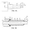
- FIGS. 1A and 1Bare a side view and a side cross-sectional view, respectively, showing an embodiment of a vacuum insulated structure with a fitting;
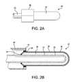
- FIGS. 2A and 2Bare a side view and a side cross-sectional view, respectively, of another embodiment of a vacuum insulated structure with a fitting;
- FIGS. 3A-3Dare side cross-sectional views illustrating a method of assembling a vacuum insulated structure with a fitting.
- FIGS. 4A-4Care side or axial cross-sectional views illustrating another embodiment of a vacuum insulated structure with different types of fittings.
- FIGS. 5A and 5Bare side views of another embodiment of a vacuum insulated structure with a fitting.
- FIGS. 1A-1B and 2 A- 2 BTwo embodiments of a vacuum insulated structure 10 are shown in FIGS. 1A-1B and 2 A- 2 B. Those embodiments are merely illustrative, it being understood that infinite other embodiments may be constructed having the same features as described herein.
- the structure 10includes a tube 20 having an inner wall 23 , a jacket 30 surrounding at least a portion of the tube 20 and having at least one end 32 , and a fitting 40 affixed to the jacket 30 .
- the tube 20is an elongate tube with a length many times its diameter.
- the jacket 30has a geometry similar to that of the tube 20 , to form a narrow annular space between the tube 20 and the jacket 30 .
- the same principles of construction as described hereinmay be applied to a tube 20 of any shape with a correspondingly shaped jacket 20 and annular space.
- the tube 20 and the jacket 30may be generally spherical in shape.
- the tube 20has an outer diameter defined by an outer wall 22 of the tube 20 .
- the jacket 30has an inner diameter that is at least slightly larger than the outer diameter of the tube 20 , so that an annular insulating space 36 is formed between the tube 20 and the jacket 30 .
- the annular insulating space 36is formed as a volume that will be put under vacuum, whereas the tube interior 26 can formed for accommodating devices, materials, or components that are desired to be insulated by annular insulating space 36 , for example a surgical probe, or a cooling device for infrared imaging electronics.
- Structure 10can also be used for, but is not limited to, insulating and installing aviation electronics and instruments for transporting tubes for oil, for transporting and storing fuel for hydrogen fuel cells, as thermal insulation for spacecraft components such as electronics, for thermal control of components of weapon systems.
- structure 10is particularly suitable when devices or materials have to be insulated from effects of very large changes in temperature.
- the temperature differencemay be in a range between ⁇ 200° C. and +150° C., and structure 10 can be exposed to temperature difference of about ⁇ 600° C.
- the annular insulating space 36may be evacuated through a vent 34 located adjacent to the end 32 of the jacket 30 .
- the vent 34is a small gap between the end 32 of the jacket 30 and the outer wall 22 of the tube 20 .
- the insulating space 30may be evacuated by placing the entire structure 10 into a vacuum chamber and then drawing a vacuum in the chamber. As the pressure in the vacuum chamber decreases, gas (usually air) escapes from the insulating space 36 via the vent 34 . Other methods for applying suction to the vent 34 may alternatively be used.
- the evacuation of the insulating space 36achieves a pressure lower than the pressure applied to the vent 34 (i.e., the level of vacuum achieved in the vacuum insulating space 36 is deeper than the level of vacuum applied to the vent 34 ) as a result of the geometry of the walls bounding the vacuum insulating space 36 in the vicinity of the vent 34 .
- the ends 32 of the jacket 30are configured in the vicinity of the vents 34 to preferentially direct gas molecules toward the vent 34 in an ultra-low pressure free molecular flow regime in which the frequency of gas molecule collisions with the walls exceeds the frequency of gas molecule collisions with each other.
- the relative geometry of the jacket 30 and the tube 20 at the jacket ends 32 adjacent to the vent 34has a guiding effect on gas molecules in a free molecular flow regime so that the flux of gas molecules out the vent 34 is greater than the flux of gas molecules into the vent 34 .
- a highly insulating space having a low vacuum created by such geometrycan be used in devices of miniature scale or in devices having insulating spaces of extremely narrow width. For example, insulating spaces 30 have been created incorporating this geometry with gaps on the order of 0.004′′ or smaller.
- the structure 10may be heated to accelerate the motion of the gas molecules within the insulating space 36 , so as to further bias the flux of gas molecules outward from the vent 34 as compared with inward into the vent 34 .
- tube 20 or the structure 10may be heated to an elevated temperature and held at that temperature for a period of time during the evacuation process. Longer hold times may be used to further increase the vacuum achievable in the insulating space 36 .
- the vent 34is sealed to maintain the vacuum.
- the vent 34is sealable by a first braze material 24 that melts and flows into the vent 34 when heated to a brazing temperature, so that the end 32 of the jacket 30 is brazed to the outer wall 22 of the tube and the insulating space 36 is sealed off.
- the use of brazing to seal the evacuation vent of a vacuum-sealed structureis generally known in the art.
- a bead of first braze material 24is positioned on the outer wall 22 of the tube 20 , slightly within the insulating space 36 , near the vent 34 and the end 32 of the jacket, as shown in FIG. 3A .
- the bead of first braze material 24Prior to heating, the bead of first braze material 24 is solid and is preferably adhered to the outer wall 22 of the tube 20 .
- the first braze materialis preferably free from flux, since flux can off-gas after brazing, thereby reducing the vacuum within the insulating jacket 36 .
- the first braze material 24is positioned between the tube 20 and the jacket 30 near the vent 34 in such a manner that during the evacuation process (i.e., prior to the brazing process) the vent 34 is not blocked by the braze material 24 .
- Toward the end of the evacuation processas the desired level of vacuum is being achieved in the insulating space 36 , sufficient heat is applied to the tube 20 or to the entire structure 10 to melt the first braze material 24 such that it flows by capillary action into the vent 34 .
- the flowing braze material 24seals the vent 34 and blocks the evacuation path from the insulating space 36 , as shown in FIG. 3B .
- first braze material 24Flowing of the first braze material 24 is facilitated by any preheating that occurs by heating of the tube 20 or the structure 10 during the evacuation phase in order to enhance the ultimate level of vacuum achieved in the insulating space 36 .
- the first braze materialforms an alloyed joint between the tube 20 and the jacket 30 .
- the joint formed by the first braze material 24is then allowed to cool, so as to solidify and seal the vent 34 closed.
- other processescan be used for sealing the vent 34 , including but not limited to a metal surgical process or a chemical process.
- Fitting 40may be attached to the structure 10 , either to the tube 20 or to the jacket 30 .
- the fitting 40is attached to the jacket 30 , noting that essentially the same process can be used for attachment to the tube 20 or the jacket 30 .
- the fitting 40is slipped over the end 32 of the jacket 30 and a bead of second braze material 44 is positioned between an outer wall 38 of the jacket 38 and an inner surface 42 of the fitting 40 .
- fitting 40is a weld or braze socket
- the fitting 40may be any fitting that enables attachment of the structure 10 to another device, and may include but is not limited to a weld socket, a braze socket, a threaded fitting, a compression-type fitting, a flange fitting, a custom fitting, and the like.
- the fitting 40 and the bead of second braze material 44are positioned as desired with respect to the jacket 30 , sufficient heat is applied to the jacket 30 or to the entire structure 10 to melt the second braze material 44 .
- the second braze materialforms an allowed joint between the jacket 30 and the fitting 40 .
- the second braze materialmay be the same as or different from the first braze material.
- the joint formed by the second braze material 44is then allowed to cool, so as to solidify and secure the fitting 40 to the jacket 30 .
- Fitting 40 shownhas an L-shape from a cross-sectional view, and can be used to attach structure 10 to a bracket (not shown).
- fittings 50 , 60 , 70 , and 80can be arranged at the tube interior 26 on the inner wall 23 , and a similar attachment process can be used as described for fitting 40 .
- FIG. 4Ashows a fitting 50 on the left side of tube 20 , having a hollow structure and being threaded for engaging with a treaded rod or screw.
- FIG. 4Ashows another fitting 60 is illustrated, comprised of webs 62 that hold a nut 64 substantially in the center of tube 20 , as shown in the cross-sectional view of FIG. 4B .
- Nut 64may have a thread in the inner bore with or without a thread. Nut 64 could also just be a thread bore, as in fitting 50 .
- FIG. 4Cshows a fitting 70 arranged on the left side of the tube 20 , having a blocking body 72 and a threaded rod 74 protruding in an axial direction away from tube 20 .
- a fitting 80illustrated on the left side of the figure can be formed as a nut or another structure with a bore.
- Fittings 50 , 60 , 70 , and 80can be used for various attachment purposes.
- fittings 50 , 60 , 70 , and 80can be used to attach structure 10 to another tube, to an additional casing or insulating structure, or for connection with dewars.
- FIG. 5Ashows an alternative embodiment in which the fitting 90 is arranged directly onto the tube 20 by use of braze material 94 , and is located between tube 20 and jacket 30 as a spacer.
- fitting 90is made of a hollow concentric structure having an inner diameter that is slightly bigger than the outer diameter of tube 20 , so that fitting 90 can be placed over tube 20 for brazing, or by another sealed attachment procedure. Fitting has a narrowed protrusion that is threaded, allowing to secure the structure 10 to a corresponding thread.
- jacket 30is affixed to tube 29 on one side, and on the other side is affixed to the fitting 90 . It is also possible that two fittings 90 are concentrically arranged at two different locations of tube 20 , and that the jacket 30 is not directly attached to the tube 20 , but to fittings 90 .
- FIG. 5Bis an exemplary method of making the vacuum inside the annular insulating space 36 , similar to the method shown with respect to FIG. 3A .
- Space 36can be evacuated through a vent 34 located adjacent to the end 32 of the jacket 30 and the outer peripheral wall of fitting 90 .
- the front end of jacketis brazed to tube 20 with material 24 .
- the insulating space 30may be evacuated by placing the entire structure 10 into a vacuum chamber and then drawing a vacuum in the chamber. As the pressure in the vacuum chamber decreases, gas escapes from the insulating space 36 via the vent 34 .
- Other methods for applying suction to the vent 34may alternatively be used.
Landscapes
- Engineering & Computer Science (AREA)
- General Engineering & Computer Science (AREA)
- Mechanical Engineering (AREA)
- Thermal Insulation (AREA)
Abstract
Description
Claims (10)
Priority Applications (5)
| Application Number | Priority Date | Filing Date | Title |
|---|---|---|---|
| US13/644,199US9243726B2 (en) | 2012-10-03 | 2012-10-03 | Vacuum insulated structure with end fitting and method of making same |
| US14/953,756US9874303B2 (en) | 2012-10-03 | 2015-11-30 | Vacuum insulated structure with end fitting and method of making same |
| US15/841,427US10495250B2 (en) | 2012-10-03 | 2017-12-14 | Vacuum insulated structure with end fitting and method of making same |
| US16/547,749US11204127B2 (en) | 2012-10-03 | 2019-08-22 | Vacuum insulated structure with end fitting and method of making same |
| US17/546,101US20220099237A1 (en) | 2012-10-03 | 2021-12-09 | Vacuum Insulated Structure With End Fitting And Method Of Making Same |
Applications Claiming Priority (1)
| Application Number | Priority Date | Filing Date | Title |
|---|---|---|---|
| US13/644,199US9243726B2 (en) | 2012-10-03 | 2012-10-03 | Vacuum insulated structure with end fitting and method of making same |
Related Child Applications (1)
| Application Number | Title | Priority Date | Filing Date |
|---|---|---|---|
| US14/953,756DivisionUS9874303B2 (en) | 2012-10-03 | 2015-11-30 | Vacuum insulated structure with end fitting and method of making same |
Publications (2)
| Publication Number | Publication Date |
|---|---|
| US20140090737A1 US20140090737A1 (en) | 2014-04-03 |
| US9243726B2true US9243726B2 (en) | 2016-01-26 |
Family
ID=50384090
Family Applications (5)
| Application Number | Title | Priority Date | Filing Date |
|---|---|---|---|
| US13/644,199Expired - Fee RelatedUS9243726B2 (en) | 2012-10-03 | 2012-10-03 | Vacuum insulated structure with end fitting and method of making same |
| US14/953,756ActiveUS9874303B2 (en) | 2012-10-03 | 2015-11-30 | Vacuum insulated structure with end fitting and method of making same |
| US15/841,427Expired - Fee RelatedUS10495250B2 (en) | 2012-10-03 | 2017-12-14 | Vacuum insulated structure with end fitting and method of making same |
| US16/547,749Active2032-12-18US11204127B2 (en) | 2012-10-03 | 2019-08-22 | Vacuum insulated structure with end fitting and method of making same |
| US17/546,101AbandonedUS20220099237A1 (en) | 2012-10-03 | 2021-12-09 | Vacuum Insulated Structure With End Fitting And Method Of Making Same |
Family Applications After (4)
| Application Number | Title | Priority Date | Filing Date |
|---|---|---|---|
| US14/953,756ActiveUS9874303B2 (en) | 2012-10-03 | 2015-11-30 | Vacuum insulated structure with end fitting and method of making same |
| US15/841,427Expired - Fee RelatedUS10495250B2 (en) | 2012-10-03 | 2017-12-14 | Vacuum insulated structure with end fitting and method of making same |
| US16/547,749Active2032-12-18US11204127B2 (en) | 2012-10-03 | 2019-08-22 | Vacuum insulated structure with end fitting and method of making same |
| US17/546,101AbandonedUS20220099237A1 (en) | 2012-10-03 | 2021-12-09 | Vacuum Insulated Structure With End Fitting And Method Of Making Same |
Country Status (1)
| Country | Link |
|---|---|
| US (5) | US9243726B2 (en) |
Cited By (14)
| Publication number | Priority date | Publication date | Assignee | Title |
|---|---|---|---|---|
| US20160084425A1 (en)* | 2012-10-03 | 2016-03-24 | Aarne H. Reid | Vacuum Insulated Structure With End Fitting And Method Of Making Same |
| US10065256B2 (en) | 2015-10-30 | 2018-09-04 | Concept Group Llc | Brazing systems and methods |
| US10497908B2 (en) | 2015-08-24 | 2019-12-03 | Concept Group, Llc | Sealed packages for electronic and energy storage devices |
| US10723538B2 (en) | 2014-02-20 | 2020-07-28 | Concept Group Llc | Vacuum insulated articles and methods of making same |
| US10823326B2 (en) | 2016-11-15 | 2020-11-03 | Concept Group Llc | Enhanced vacuum-insulated articles with controlled microporous insulation |
| US20200409438A1 (en)* | 2019-06-26 | 2020-12-31 | Micron Technology, Inc. | Apparatus, methods and systems for thermally isolated signal and power transmission |
| US11008153B2 (en) | 2016-11-15 | 2021-05-18 | Concept Group Llp | Multiply-insulated assemblies |
| CN113074496A (en)* | 2020-01-06 | 2021-07-06 | 青岛海尔电冰箱有限公司 | Refrigerator with a door |
| US11174033B2 (en)* | 2015-12-02 | 2021-11-16 | Hutchinson | Metal insulating part |
| US11320086B2 (en) | 2017-08-25 | 2022-05-03 | Concept Group Llc | Multiple geometry and multiple material insulated components |
| US11702271B2 (en) | 2016-03-04 | 2023-07-18 | Concept Group Llc | Vacuum insulated articles with reflective material enhancement |
| US11956924B1 (en) | 2020-08-10 | 2024-04-09 | Montana Instruments Corporation | Quantum processing circuitry cooling systems and methods |
| US12071998B2 (en) | 2018-10-09 | 2024-08-27 | Montana Instruments Corporation | Cryocooler assemblies and methods |
| US12253205B1 (en)* | 2018-09-28 | 2025-03-18 | Montana Instruments Corporation | Thermal transfer line assemblies, methods of manufacturing thermal transfer line assemblies, and thermal transfer methods |
Families Citing this family (11)
| Publication number | Priority date | Publication date | Assignee | Title |
|---|---|---|---|---|
| US11185795B2 (en) | 2012-07-06 | 2021-11-30 | Waters Technologies Corporation | Techniques for thermally insulating a chromatographic column |
| GB2586100B (en) | 2012-07-06 | 2021-04-28 | Waters Technologies Corp | Techniques for thermally insulating a liquid chromatographic column |
| US10973996B2 (en) | 2014-07-15 | 2021-04-13 | Ron Nagar | Devices, systems and methods for controlling conditions and delivery of substances |
| WO2017090019A2 (en) | 2015-11-23 | 2017-06-01 | Ron Nagar | Devices, systems and methods for controlling environmental conditions of substances |
| MX2020000116A (en) | 2017-07-07 | 2020-08-06 | Concept Group Llc | Joint configurations for vacuum-insulated articles. |
| US20200362997A1 (en)* | 2017-11-14 | 2020-11-19 | Concept Group Llc | Insulated connector components |
| CN112165913A (en)* | 2018-04-17 | 2021-01-01 | 概念集团有限责任公司 | Joint arrangement |
| JP2022504099A (en) | 2018-10-24 | 2022-01-13 | ロン・ナガル | Devices, systems and methods for controlling the environmental conditions of substances |
| EP3887707A4 (en)* | 2018-11-30 | 2022-09-07 | Concept Group LLC | Joint configurations |
| CN111022784B (en)* | 2019-12-20 | 2021-03-09 | 信达科创(唐山)石油设备有限公司 | Ultra-long heat-insulating pipeline and processing method thereof |
| CN113074502A (en) | 2020-01-06 | 2021-07-06 | 青岛海尔电冰箱有限公司 | Refrigeration module and refrigerator |
Citations (44)
| Publication number | Priority date | Publication date | Assignee | Title |
|---|---|---|---|---|
| US2666979A (en)* | 1948-03-06 | 1954-01-26 | Dusen Engineering Company Van | Method for attaching members by vacuum pressure |
| US2867242A (en)* | 1956-01-16 | 1959-01-06 | North American Aviation Inc | High pressure flexible hose |
| US3265236A (en) | 1962-05-10 | 1966-08-09 | Union Carbide Corp | Thermal insulation |
| US3706208A (en)* | 1971-01-13 | 1972-12-19 | Air Prod & Chem | Flexible cryogenic liquid transfer system and improved support means therefor |
| US4055268A (en)* | 1975-11-18 | 1977-10-25 | Union Carbide Corporation | Cryogenic storage container |
| US4653469A (en)* | 1984-08-08 | 1987-03-31 | Nippon Sanso Kabushiki Kaisha | Vacuum-heat-insulated cooking utensil and method of manufacturing same |
| US5108390A (en) | 1988-11-14 | 1992-04-28 | Frigitronics, Inc. | Flexible cryoprobe |
| US5520682A (en) | 1991-09-06 | 1996-05-28 | Cryomedical Sciences, Inc. | Cryosurgical instrument with vent means and method using same |
| US5573140A (en)* | 1992-12-24 | 1996-11-12 | Nippon Sanso Corporation | Metallic vacuum double-walled container |
| US5600752A (en)* | 1994-03-11 | 1997-02-04 | Industrial Design Laboratories, Inc. | Flexible gas hose assembly with concentric helical tube members having reinforcement spring coils |
| US5674218A (en) | 1990-09-26 | 1997-10-07 | Cryomedical Sciences, Inc. | Cryosurgical instrument and system and method of cryosurgery |
| US5870823A (en) | 1996-11-27 | 1999-02-16 | International Business Machines Corporation | Method of forming a multilayer electronic packaging substrate with integral cooling channels |
| US6166907A (en) | 1999-11-26 | 2000-12-26 | Chien; Chuan-Fu | CPU cooling system |
| EP1294022A2 (en) | 2001-09-12 | 2003-03-19 | Harris Corporation | Electronic module including a cooling substrate having a fluid cooling circuit therein and related methods |
| WO2003025476A2 (en) | 2001-09-07 | 2003-03-27 | Raytheon Company | Microelectronic system with integral cyrocooler, and its fabrication and use |
| US6706037B2 (en) | 2000-10-24 | 2004-03-16 | Galil Medical Ltd. | Multiple cryoprobe apparatus and method |
| US6875209B2 (en) | 2001-09-27 | 2005-04-05 | Galil Medical Ltd. | Cryoplasty apparatus and method |
| US6936045B2 (en) | 2001-09-20 | 2005-08-30 | Endocare, Inc. | Malleable cryosurgical probe |
| US7064429B2 (en) | 2001-06-20 | 2006-06-20 | Infineon Technologies Ag | Electronic package having integrated cooling element with clearance for engaging package |
| US7139172B2 (en) | 2004-07-01 | 2006-11-21 | International Business Machines Corporation | Apparatus and methods for microchannel cooling of semiconductor integrated circuit packages |
| US20060282039A1 (en) | 2005-06-09 | 2006-12-14 | Endocare, Inc. | Heat exchange catheter with multi-lumen tube having a fluid return passageway |
| US7203064B2 (en) | 2003-12-12 | 2007-04-10 | Intel Corporation | Heat exchanger with cooling channels having varying geometry |
| US7207985B2 (en) | 2003-06-25 | 2007-04-24 | Endocare, Inc. | Detachable cryosurgical probe |
| US7258161B2 (en) | 2002-01-14 | 2007-08-21 | Emerson Network Power, Energy Systems, North America, Inc. | Cooling system for densely packed electronic components |
| US7298623B1 (en) | 2006-06-29 | 2007-11-20 | International Business Machines Corporation | Organic substrate with integral thermal dissipation channels, and method for producing same |
| USRE40049E1 (en) | 1999-06-25 | 2008-02-12 | Ams Research Corporation | Precooled cryogenic ablation system |
| US20080036076A1 (en) | 2006-08-11 | 2008-02-14 | Sun Microsystems, Inc. | Intelligent cooling method combining passive and active cooling components |
| US7334630B2 (en) | 2001-09-28 | 2008-02-26 | The Board Of Trustees Of The Leland Stanford Junior University | Closed-loop microchannel cooling system |
| US7361187B2 (en) | 2003-06-25 | 2008-04-22 | Endocare, Inc. | Threaded cryostat for cryosurgical probe system |
| US7374063B2 (en) | 2004-03-23 | 2008-05-20 | Concept Group Inc. | Vacuum insulated structures |
| US7393350B2 (en) | 2002-08-06 | 2008-07-01 | Erbe Elektromedizin Gmbh | Cryo-surgical apparatus and methods |
| US7451785B2 (en)* | 2002-12-26 | 2008-11-18 | Hirotec Corporation | Flexible tube |
| US20080285230A1 (en) | 2006-08-10 | 2008-11-20 | Siemens Vdo Automotive Ag | Electronic Unit with Sealed Coolant Passage |
| US7460369B1 (en) | 2007-06-01 | 2008-12-02 | Advanced Micro Devices, Inc. | Counterflow microchannel cooler for integrated circuits |
| US7510534B2 (en) | 2001-07-20 | 2009-03-31 | Ethicon Endo-Surgery, Inc. | Method for operating biopsy device |
| US7515415B2 (en) | 2006-02-02 | 2009-04-07 | Sun Microsystems, Inc. | Embedded microchannel cooling package for a central processor unit |
| US7608071B2 (en) | 2003-06-25 | 2009-10-27 | Endocare, Inc. | Cryosurgical probe with adjustable sliding apparatus |
| US7621889B2 (en) | 2005-06-09 | 2009-11-24 | Endocare, Inc. | Heat exchange catheter and method of use |
| US20100057067A1 (en) | 2008-09-03 | 2010-03-04 | Baust John M | Modular pulsed pressure device for the transport of liquid cryogen to a cryoprobe |
| US20100057064A1 (en) | 2008-09-03 | 2010-03-04 | Baust John M | Medical Device for the Transport of Subcooled Cryogenic Fluid through a Linear Heat Exchanger |
| US20100076421A1 (en) | 2008-09-19 | 2010-03-25 | Baust John M | Nucleation Enhanced Surface Modification to Support Physical Vapor Deposition to Create a Vacuum |
| US7909227B2 (en)* | 2006-12-19 | 2011-03-22 | Endocare, Inc. | Cryosurgical probe with vacuum insulation tube assembly |
| US20110264084A1 (en) | 2010-04-23 | 2011-10-27 | Concept Group, Inc. | Vacuum insulated cooling probe with heat exchanger |
| US8353332B2 (en)* | 2010-10-13 | 2013-01-15 | Reid Aarne H | Integrated electronics cooling device |
Family Cites Families (186)
| Publication number | Priority date | Publication date | Assignee | Title |
|---|---|---|---|---|
| US1362805A (en) | 1918-04-30 | 1920-12-21 | Bliss E W Co | Horn-extension support |
| US1457504A (en) | 1919-03-20 | 1923-06-05 | American Can Co | Soldering machine |
| US2085737A (en) | 1933-04-13 | 1937-07-06 | American Can Co | Can soldering machine |
| GB509913A (en) | 1937-03-08 | 1939-07-24 | Jean Baptiste Monier | Process for manufacturing synthetic resin compounds |
| US2225660A (en)* | 1939-11-16 | 1940-12-24 | George D Rogers | Pouring spout |
| US2362893A (en) | 1942-04-04 | 1944-11-14 | Metals & Controls Corp | Solder |
| US2573594A (en) | 1947-08-21 | 1951-10-30 | Gibson Refrigerator Co | Soldering machine |
| US2722336A (en)* | 1951-03-08 | 1955-11-01 | Westinghouse Electric Corp | Thermal insulated container |
| US2845199A (en)* | 1955-01-06 | 1958-07-29 | Mine Safety Appliances Co | Container |
| US2807074A (en) | 1955-09-27 | 1957-09-24 | Griscom Russell Co | Manufacture of brazed finned tubing and the like |
| US3068026A (en) | 1958-06-13 | 1962-12-11 | Gen Motors Corp | Cryogenic fluid transfer line coupling |
| US3090463A (en) | 1960-02-15 | 1963-05-21 | John D Yanda | Engine vacuum sound barrier |
| US3152452A (en)* | 1960-12-21 | 1964-10-13 | Union Carbide Corp | Vacuum-insulated valved coupling |
| US3146005A (en) | 1961-12-04 | 1964-08-25 | Arrowhead Products | Vacuum insulated conduits and insulated joining means |
| US3195564A (en)* | 1962-10-01 | 1965-07-20 | Union Carbide Corp | Vacuum-insulated valve for cryogenic fluids |
| US3119238A (en) | 1963-02-18 | 1964-01-28 | William H Chamberlain | Cryogenic dewar |
| US3457723A (en) | 1965-03-22 | 1969-07-29 | Walker Mfg Co | Exhaust system |
| US3510323A (en) | 1965-10-21 | 1970-05-05 | Ppg Industries Inc | Heat resistant inorganic foams and their method of manufacture |
| US3460512A (en) | 1965-11-18 | 1969-08-12 | Stern Metals Corp | Apparatus for depositing a solder strip on a base metal band |
| US3736936A (en) | 1971-12-13 | 1973-06-05 | Hughes Aircraft Co | Cryogenic heat transfer device |
| US3799440A (en)* | 1972-03-02 | 1974-03-26 | American Aero Ind | Safety apparatus |
| US3760142A (en) | 1972-07-31 | 1973-09-18 | Western Electric Co | Soldering apparatus having a non-uniform heat transfer distribution |
| US4011732A (en)* | 1974-02-14 | 1977-03-15 | Helix Technology Incorporated | Heat-stationed bayonet connector for cryogenic fluid lines |
| US3988029A (en)* | 1974-08-28 | 1976-10-26 | Kaiser Aerospace And Electronics Corporation | Cryogenic fluid coupling device |
| US3943618A (en)* | 1974-12-30 | 1976-03-16 | Atlantic Richfield Company | Method of assembly of a dual-walled pipe |
| US4117201A (en)* | 1976-07-23 | 1978-09-26 | Fansteel Inc. | Corrosion and erosion resistant lined equipment |
| US4399919A (en) | 1977-02-23 | 1983-08-23 | Mario Posnansky | Vacuum flask |
| US4151828A (en)* | 1977-06-28 | 1979-05-01 | Solarpower, Inc. | Solar energy collection tube |
| US4200199A (en) | 1977-09-01 | 1980-04-29 | Aladdin Industries, Incorporated | Vacuum bottle construction |
| JPS5459662A (en)* | 1977-10-20 | 1979-05-14 | Nippon Oxygen Co Ltd | Preparation of thermos in metal |
| US4332401A (en) | 1979-12-20 | 1982-06-01 | General Electric Company | Insulated casing assembly |
| US4396211A (en) | 1981-06-10 | 1983-08-02 | Baker International Corporation | Insulating tubular conduit apparatus and method |
| DE3135472A1 (en) | 1981-09-08 | 1983-03-17 | Roland 7953 Bad Schussenried Kistler | CLAMPING AND TURNING DEVICE FOR ROUND WORKPIECES, IN PARTICULAR WELDING AID DEVICE |
| US4491347A (en)* | 1982-01-04 | 1985-01-01 | Minnesota Valley Engineering, Inc. | Cryogenic connector |
| US4450872A (en) | 1982-06-18 | 1984-05-29 | The Babcock & Wilcox Company | Fiber pipe protection for water cooled pipes in reheat furnaces |
| US4538337A (en)* | 1982-08-31 | 1985-09-03 | The Babcock & Wilcox Company | Method of mechanically prestressing a tubular apparatus |
| US4515397A (en) | 1983-04-01 | 1985-05-07 | Union Carbide Corporation | Vacuum insulated conduit |
| SE466299B (en) | 1983-08-04 | 1992-01-27 | Micropore International Ltd | HEAT-INSULATING BODY AND MAKING IT MANUFACTURED, INCLUDING A REINFORCING HONEY STRUCTURE AND A HEATING INSULATION MATERIAL |
| US4758222A (en) | 1985-05-03 | 1988-07-19 | Mccoy William C | Steerable and aimable catheter |
| US4696104A (en) | 1985-06-07 | 1987-09-29 | Vanzetti Systems, Inc. | Method and apparatus for placing and electrically connecting components on a printed circuit board |
| US4746054A (en) | 1985-08-29 | 1988-05-24 | Northrop Corporation | Method of joining concentric cylinders |
| FR2597571B1 (en) | 1986-03-18 | 1989-04-21 | Caubet Jacques Jean | THERMAL INSULATION DEVICE AND ITS APPLICATIONS |
| US4838859A (en) | 1987-05-19 | 1989-06-13 | Steve Strassmann | Steerable catheter |
| GB2205297B (en) | 1987-06-05 | 1991-06-19 | Lin Pac Mouldings | A container assembly |
| US5372138A (en) | 1988-03-21 | 1994-12-13 | Boston Scientific Corporation | Acousting imaging catheters and the like |
| US5318108A (en) | 1988-04-15 | 1994-06-07 | Midwest Research Institute | Gas-controlled dynamic vacuum insulation with gas gate |
| KR920009830B1 (en) | 1988-04-20 | 1992-10-31 | 조지루시마호빈 가부시키가이샤 | Vacuum-insulated, double walled metal structure and method for its production |
| US4903631A (en) | 1988-05-27 | 1990-02-27 | Teledyne Industries, Inc. | System for soldering printed circuits |
| US5038706A (en) | 1988-05-27 | 1991-08-13 | Teledyne Industries, Inc. | Printed circuits board soldering apparatus |
| US5052816A (en) | 1989-08-29 | 1991-10-01 | Denyo Kabushiki Kaisha | Junction inspection method and apparatus for electronic parts |
| JPH0794972B2 (en) | 1989-12-13 | 1995-10-11 | 松下電器産業株式会社 | Solder appearance inspection method |
| US5235817A (en) | 1992-04-02 | 1993-08-17 | North American Philips Corp. | Cryogenic cooling apparatus for radiation detector |
| US5285559A (en) | 1992-09-10 | 1994-02-15 | Sundstrand Corporation | Method and apparatus for isolating electronic boards from shock and thermal environments |
| JPH0741413B2 (en) | 1992-11-11 | 1995-05-10 | 外山工業株式会社 | Paste type brazing material automatic feeder |
| EP0611614A1 (en) | 1993-02-16 | 1994-08-24 | B & W FUEL COMPANY | Device for forming a mechanical connection between two concentric tubes |
| DE4324051C2 (en) | 1993-07-17 | 2002-05-02 | Brugg Rohrsysteme Gmbh | Pipe section for a pipe system for the transport of district heating and pipe system |
| US5393260A (en) | 1993-12-10 | 1995-02-28 | Eljer Manufacturing, Inc. | Flexible double wall vent pipe |
| US5411897A (en) | 1994-02-04 | 1995-05-02 | Mobil Solar Energy Corporation | Machine and method for applying solder paste to electronic devices such as solar cells |
| JP2622531B2 (en) | 1994-06-03 | 1997-06-18 | 株式会社イースタン | Colored solder material and method for forming colored film on soldered part |
| US5756934A (en) | 1994-10-11 | 1998-05-26 | Loral Fairchild Corp. | Flight crash survivable storage unit with aquarium container for flight recorder memory |
| US5573532A (en) | 1995-01-13 | 1996-11-12 | Cryomedical Sciences, Inc. | Cryogenic surgical instrument and method of manufacturing the same |
| US5869801A (en) | 1995-02-15 | 1999-02-09 | The E.O. Paton Electric Welding Institute Of The National Academy Of Sciences Of Ukraine, | Device for manual electron beam processing of materials in space |
| JP3230136B2 (en) | 1995-04-12 | 2001-11-19 | 東拓工業株式会社 | Washing machine hose |
| JP4029362B2 (en) | 1995-06-30 | 2008-01-09 | 澁谷工業株式会社 | Adsorption leak detection device for adsorption head |
| JP3261969B2 (en) | 1996-02-29 | 2002-03-04 | 豊田合成株式会社 | Hose and manufacturing method |
| FR2746891B1 (en) | 1996-03-29 | 1998-06-05 | Itp | PIPE FOR DUAL THERMAL INSULATING PIPE TYPE PIPES |
| WO1998015772A1 (en)* | 1996-10-08 | 1998-04-16 | Process Systems International, Inc. | Swivel bayonet joint, system and method for cryogenic fluids |
| US5862973A (en) | 1997-01-30 | 1999-01-26 | Teradyne, Inc. | Method for inspecting solder paste in printed circuit board manufacture |
| US6139571A (en) | 1997-07-09 | 2000-10-31 | Fuller Research Corporation | Heated fluid surgical instrument |
| KR100254323B1 (en) | 1997-08-01 | 2000-05-01 | 윤종용 | Soldering method and apparatus for tcp integrated circuits |
| JP3335896B2 (en) | 1997-12-26 | 2002-10-21 | 株式会社東芝 | Solder material and method for manufacturing solder material |
| FR2777630B1 (en) | 1998-04-16 | 2000-06-16 | Roll & Concept Sa | TUBULAR AND ALVEOLAR BODY |
| DE19840841B4 (en) | 1998-09-07 | 2007-02-08 | Michael Hörauf Maschinenfabrik GmbH & Co. KG | Heat-insulating mug |
| US6216745B1 (en)* | 1998-10-28 | 2001-04-17 | Mve, Inc. | Vacuum insulated pipe |
| US6257282B1 (en) | 1998-10-28 | 2001-07-10 | Mve, Inc. | Vacuum insulated pipe |
| US6203764B1 (en) | 1999-01-15 | 2001-03-20 | Midwest Research Institute | Vacuum-insulated catalytic converter |
| US6908595B1 (en) | 1999-01-22 | 2005-06-21 | Benteler Automotive Corporation | Vacuum-insulated exhaust treatment devices, such as catalytic converters, with passive controls |
| US6360935B1 (en) | 1999-01-26 | 2002-03-26 | Board Of Regents Of The University Of Texas System | Apparatus and method for assessing solderability |
| US6050443A (en) | 1999-02-17 | 2000-04-18 | Tung; Kuang Pao | Double layer mug |
| US7935108B2 (en) | 1999-07-14 | 2011-05-03 | Cardiofocus, Inc. | Deflectable sheath catheters |
| JP4346054B2 (en) | 2000-01-18 | 2009-10-14 | 栄修 永田 | Soldering method and soldering apparatus |
| WO2001076431A1 (en) | 2000-04-12 | 2001-10-18 | Nippon Sanso Corporation | Heat insulating container |
| DE10019420A1 (en) | 2000-04-19 | 2001-10-31 | Bosch Gmbh Robert | Solder melting monitoring device evaluates detected electromagnetic radiation reflected from solder joint for providing solder parameter |
| US6634241B1 (en) | 2000-09-22 | 2003-10-21 | Micro Motion, Inc. | Method and apparatus for bonding a connecting ring to a flow tube and balance bar of a coriolis flowmeter |
| US6955284B2 (en) | 2000-10-06 | 2005-10-18 | Pac Tec-Packaging Technologies Gmbh | Device for positioning a tool in relation to a workpiece |
| EP1401731A2 (en) | 2000-11-29 | 2004-03-31 | American Aerogel Corporation | Insulated barriers and methods for producing same |
| US6755823B2 (en) | 2001-02-28 | 2004-06-29 | Cryocath Technologies Inc. | Medical device with enhanced cooling power |
| GB2383321B (en) | 2001-12-21 | 2005-07-27 | Ebac Ltd | Feed tube for use in a liquid delivery system |
| JP3654249B2 (en) | 2002-01-16 | 2005-06-02 | タイガー魔法瓶株式会社 | rice cooker |
| US6951554B2 (en) | 2002-12-16 | 2005-10-04 | Intraluminal Therapeutics Inc. | Deflecting catheter |
| US7276062B2 (en) | 2003-03-12 | 2007-10-02 | Biosence Webster, Inc. | Deflectable catheter with hinge |
| US7663073B2 (en) | 2003-05-13 | 2010-02-16 | Panasonic Corporation | Optical processing apparatus |
| US7419085B2 (en) | 2003-05-13 | 2008-09-02 | Matsushita Electric Industrial Co., Ltd. | Optical processing apparatus |
| KR20060019576A (en) | 2003-07-04 | 2006-03-03 | 마쯔시다덴기산교 가부시키가이샤 | Vacuum Insulation Materials and Devices Using the Same |
| TWI338262B (en)* | 2003-07-25 | 2011-03-01 | Hon Hai Prec Ind Co Ltd | A system and method for managing module development |
| JP2005224832A (en) | 2004-02-12 | 2005-08-25 | High Energy Accelerator Research Organization | Method and apparatus for manufacturing electron accelerator tube |
| EP1783837A4 (en) | 2004-05-28 | 2007-09-26 | Mech Corp | APPARATUS FOR MANUFACTURING SOLAR BATTERY CELL |
| US7322378B2 (en)* | 2004-10-28 | 2008-01-29 | Winbond Electronics Corp. | Semiconductor apparatuses and pipe supports thereof |
| US7305837B2 (en)* | 2004-09-16 | 2007-12-11 | Praxair Technology, Inc. | Cryogenic piping system |
| US7143788B2 (en) | 2004-09-20 | 2006-12-05 | Thermacor Process, Lp | High temperature line expansion installation with bellows |
| DE102004047359B3 (en) | 2004-09-29 | 2006-01-26 | eupec Europäische Gesellschaft für Leistungshalbleiter mbH | Method and device for controlling and monitoring a soldering process |
| GB2418729A (en) | 2004-09-30 | 2006-04-05 | Mv Res Ltd | Determination of solder paste composition quality by measuring emitted fluorescence radiation intensity |
| US7980171B2 (en) | 2004-10-07 | 2011-07-19 | All-Clad Metalcrafters Llc | Vacuum cooking or warming appliance |
| US20060086773A1 (en) | 2004-10-27 | 2006-04-27 | Sanftleben Henry M | Technique for optical inspection system verification |
| KR20080011272A (en) | 2005-01-24 | 2008-02-01 | 서모백 리미티드 | Heat Insulated Panel Empty |
| US20060213566A1 (en) | 2005-03-25 | 2006-09-28 | Johnson David J | Vacuum insulated exhaust system |
| CA2589805A1 (en) | 2005-03-28 | 2006-10-05 | Thermos K.K. | Heat insulated container and manufacturing method thereof |
| US7356434B2 (en) | 2005-05-12 | 2008-04-08 | Taiwan Semiconductor Manufacturing Co., Ltd. | Method of specifying pin states for a memory chip |
| JP2007046772A (en) | 2005-07-13 | 2007-02-22 | Toyoda Gosei Co Ltd | Resin pipe and resin mold article |
| DE102005053553A1 (en) | 2005-11-08 | 2007-05-16 | Heraeus Gmbh W C | Solder pastes with resin-free flux |
| US20070102477A1 (en) | 2005-11-10 | 2007-05-10 | Speedline Technologies, Inc. | Imaging system and method for a stencil printer |
| US20070102478A1 (en) | 2005-11-10 | 2007-05-10 | Speedline Technologies, Inc. | Optimal imaging system and method for a stencil printer |
| JP4170335B2 (en) | 2005-12-16 | 2008-10-22 | インターナショナル・ビジネス・マシーンズ・コーポレーション | Paste coating apparatus and PoP automatic mounting apparatus using the same |
| US8282884B2 (en) | 2006-02-27 | 2012-10-09 | Kyocera Corporation | Reacting apparatus, method of assembling reacting apparatus and reactor containing package |
| US20070235499A1 (en) | 2006-04-07 | 2007-10-11 | Jaffe Limited | Rotating type soldering device |
| US20070246510A1 (en) | 2006-04-07 | 2007-10-25 | Jaffe Limited | Rotating type soldering device |
| US20070235498A1 (en) | 2006-04-07 | 2007-10-11 | Jaffe Limited | Rotating type soldering device |
| US20070235497A1 (en) | 2006-04-07 | 2007-10-11 | Jaffe Limited | Rotating type soldering device |
| US20070270679A1 (en) | 2006-05-17 | 2007-11-22 | Duy Nguyen | Deflectable variable radius catheters |
| JP3962782B1 (en) | 2006-08-11 | 2007-08-22 | 国立大学法人 岡山大学 | Soldering inspection method, solder bonding method, and solder bonding apparatus |
| US20080083816A1 (en) | 2006-10-04 | 2008-04-10 | Leinbach Glen E | Statistical process control of solder paste stenciling using a replicated solder paste feature distributed across a printed circuit board |
| US20080169037A1 (en)* | 2007-01-17 | 2008-07-17 | Cryotech International, Inc. | Cryogenic bayonet connection |
| US7710611B2 (en) | 2007-02-16 | 2010-05-04 | Illinois Tool Works, Inc. | Single and multi-spectral illumination system and method |
| FR2918149B1 (en) | 2007-06-29 | 2009-09-25 | Inst Francais Du Petrole | REINFORCED DRIVE WITH TWO ENVELOPES AND METHOD OF MANUFACTURE. |
| US8517749B2 (en) | 2007-09-07 | 2013-08-27 | American Superconductor Corporation | System for quick disconnect termination or connection for cryogenic transfer lines with simultaneous electrical connection |
| US20090065497A1 (en) | 2007-09-07 | 2009-03-12 | Bose Corporation | Induction cookware |
| DE102007052243A1 (en) | 2007-11-02 | 2009-05-07 | Daimler Ag | Exhaust pipe component |
| WO2009068255A1 (en) | 2007-11-26 | 2009-06-04 | Danelec Electronics A/S | A voyage data recorder |
| US20120085070A1 (en) | 2007-12-11 | 2012-04-12 | TOKITAE LLC, a limited liability company of the State of Delaware | Establishment and maintenance of low gas pressure within interior spaces of temperature-stabilized storage systems |
| US20110178514A1 (en) | 2008-06-18 | 2011-07-21 | Alexander Levin | Cryosurgical Instrument Insulating System |
| US8205643B2 (en)* | 2008-10-16 | 2012-06-26 | Woodward, Inc. | Multi-tubular fluid transfer conduit |
| JP5099064B2 (en) | 2009-04-07 | 2012-12-12 | パナソニック株式会社 | Electronic component mounting system and electronic component mounting method |
| WO2010118315A1 (en) | 2009-04-10 | 2010-10-14 | Shell Oil Company | Treatment methodologies for subsurface hydrocarbon containing formations |
| DE102009042569B3 (en) | 2009-09-23 | 2011-05-05 | SCHLÖGL, Hilde | plug-in coupling |
| DE102009053575B4 (en) | 2009-11-06 | 2016-06-30 | Ekra Automatisierungssysteme Gmbh | Method and device for printing a substrate, in particular a printed circuit board, with a printing paste |
| JP5758087B2 (en) | 2010-06-02 | 2015-08-05 | 矢崎総業株式会社 | Wire harness |
| CN202001825U (en) | 2010-06-15 | 2011-10-05 | 林世鸿 | Special cryogenic heat-insulation gas bottle for nitrogen gas engine |
| DE202010008131U1 (en) | 2010-07-21 | 2010-10-07 | Funke Kunststoffe Gmbh | Reducer for pipe connection sleeve |
| US10253918B2 (en) | 2010-12-21 | 2019-04-09 | Savsu Technologies Llc | Insulated storage and transportation containers |
| CN102071879B (en) | 2011-01-07 | 2013-07-10 | 中国石油集团渤海石油装备制造有限公司 | Novel prestressed heat-insulation oil pipe |
| CN102072363B (en) | 2011-01-19 | 2013-06-19 | 湖北贵族真空科技股份有限公司 | Multi-layer single vacuum compound heat-insulation pipe |
| EP2670328B1 (en) | 2011-02-01 | 2019-10-16 | Channel Medsystems, Inc. | Apparatus for cyrogenic treatment of a body cavity or lumen |
| DE102011010385A1 (en) | 2011-02-05 | 2012-08-09 | Eads Deutschland Gmbh | Double-walled pipe and manufacturing process |
| CN103826481B (en) | 2011-09-06 | 2016-08-17 | 英美烟草(投资)有限公司 | Heating smokeable material |
| RU2608712C2 (en) | 2011-09-06 | 2017-01-23 | Бритиш Америкэн Тобэкко (Инвестментс) Лимитед | Insulation |
| KR101832763B1 (en) | 2011-11-02 | 2018-02-28 | 엘지전자 주식회사 | A refrigerator comprising a vacuum space |
| US8792238B2 (en) | 2012-02-03 | 2014-07-29 | Celsia Technologies Taiwan, Inc. | Heat-dissipating module having loop-type vapor chamber |
| US9071907B2 (en) | 2012-04-02 | 2015-06-30 | Whirpool Corporation | Vacuum insulated structure tubular cabinet construction |
| US20140008417A1 (en) | 2012-07-03 | 2014-01-09 | FLUX Brazing Schweiss- und Lotstoffe USA, LLC | Extruded brazing ring with integrated flux |
| US9243726B2 (en)* | 2012-10-03 | 2016-01-26 | Aarne H. Reid | Vacuum insulated structure with end fitting and method of making same |
| FR3000267B1 (en) | 2012-12-20 | 2021-04-16 | Airbus Operations Sas | AIRCRAFT FLIGHT DATA RECORDER |
| JP5861040B2 (en) | 2012-12-27 | 2016-02-16 | パナソニックIpマネジメント株式会社 | Paste transfer unit, electronic component mounting apparatus, and transfer film thickness measuring method |
| US10339648B2 (en) | 2013-01-18 | 2019-07-02 | H. Lee Moffitt Cancer Center And Research Institute, Inc. | Quantitative predictors of tumor severity |
| US9877767B2 (en) | 2013-03-14 | 2018-01-30 | Cpsi Holdings Llc | Endoscopic cryoablation catheter |
| GB2515992A (en) | 2013-03-22 | 2015-01-14 | British American Tobacco Co | Heating smokeable material |
| JP6158673B2 (en) | 2013-04-26 | 2017-07-05 | 矢崎総業株式会社 | Waterproof structure of electronic component storage unit |
| US9151531B2 (en) | 2013-05-16 | 2015-10-06 | Sandy Wengreen | Storage systems and methods for medicines |
| JP6212553B2 (en) | 2013-06-21 | 2017-10-11 | 川崎重工業株式会社 | Liquefied gas holding tank and liquefied gas carrier |
| WO2015023732A1 (en) | 2013-08-13 | 2015-02-19 | H. Lee Moffitt Cancer Center And Research Institute, Inc. | Systems, methods and devices for analyzing quantitative information obtained from radiological images |
| US9676064B2 (en) | 2013-10-23 | 2017-06-13 | Aarne H Reid | Controllably-formed brazing structures and related compositions and methods |
| US20150149800A1 (en) | 2013-11-27 | 2015-05-28 | Alexander Gendler | Performing an operating frequency change using a dynamic clock control technique |
| US9546481B2 (en) | 2013-12-06 | 2017-01-17 | Samsung Electronics Co., Ltd. | Vacuum insulation material |
| DE102013114552A1 (en) | 2013-12-19 | 2015-06-25 | Pi-Design Ag | Double-walled drinking vessel |
| DE102013114447B4 (en) | 2013-12-19 | 2016-01-28 | Pac Tech - Packaging Technologies Gmbh | Device for isolated application of solder material depots |
| DE102013114453A1 (en) | 2013-12-19 | 2015-06-25 | Pac Tech-Packaging Technologies Gmbh | Device for isolated application of solder material depots |
| JP2017504390A (en) | 2013-12-24 | 2017-02-09 | セント・ジュード・メディカル,カーディオロジー・ディヴィジョン,インコーポレイテッド | A deflectable catheter body having a corrugated structure |
| US9463918B2 (en) | 2014-02-20 | 2016-10-11 | Aarne H. Reid | Vacuum insulated articles and methods of making same |
| CN106132613B (en) | 2014-03-07 | 2018-11-09 | 株式会社富士 | Solder feedway |
| US20150271927A1 (en) | 2014-03-18 | 2015-09-24 | Tektronix, Inc. | Integrated soldering device |
| US9829124B2 (en) | 2014-06-18 | 2017-11-28 | United Technologies Corporation | Double wall tube assemblies |
| DE102014109934A1 (en) | 2014-07-15 | 2016-01-21 | Pac Tech - Packaging Technologies Gmbh | Device for isolated application of connection material depots |
| DE102014224270A1 (en) | 2014-11-27 | 2016-06-02 | Pi-Design Ag | Double-walled drinking vessel |
| US10037388B2 (en) | 2015-04-27 | 2018-07-31 | Microsoft Technology Licensing, Llc | Fast querying of social network data |
| DE102015112272B4 (en) | 2015-07-27 | 2020-12-17 | Schlemmer Gmbh | Foldable corrugated hose, cable harness and method for producing such a hinged corrugated hose |
| US10497908B2 (en) | 2015-08-24 | 2019-12-03 | Concept Group, Llc | Sealed packages for electronic and energy storage devices |
| US9671109B2 (en) | 2015-10-15 | 2017-06-06 | Linwood F. Hamilton | Chimney cleaner |
| US10065256B2 (en) | 2015-10-30 | 2018-09-04 | Concept Group Llc | Brazing systems and methods |
| CN109154641B (en) | 2016-03-04 | 2021-09-17 | 概念集团有限责任公司 | Vacuum insulation article with reflective material enhancement |
| CA3043915A1 (en) | 2016-11-15 | 2018-05-24 | Concept Group Llc | Enhanced vacuum-insulated articles with microporous insulation |
| WO2018093776A1 (en) | 2016-11-15 | 2018-05-24 | Reid Aarne H | Enhanced vacuum-insulated articles with controlled thermal pathways |
| WO2018093773A1 (en) | 2016-11-15 | 2018-05-24 | Reid Aarne H | Multiply-insulated assemblies |
| MX2020000116A (en) | 2017-07-07 | 2020-08-06 | Concept Group Llc | Joint configurations for vacuum-insulated articles. |
| US20210088173A1 (en) | 2017-07-12 | 2021-03-25 | Concept Group Llc | Vacuum insulated articles with reflective material enhancement |
| US11320086B2 (en) | 2017-08-25 | 2022-05-03 | Concept Group Llc | Multiple geometry and multiple material insulated components |
| US20210212175A1 (en) | 2018-04-16 | 2021-07-08 | Concept Group Llc | Thermally-insulated induction heating modules and related methods |
| EP3887707A4 (en) | 2018-11-30 | 2022-09-07 | Concept Group LLC | Joint configurations |
- 2012
- 2012-10-03USUS13/644,199patent/US9243726B2/ennot_activeExpired - Fee Related
- 2015
- 2015-11-30USUS14/953,756patent/US9874303B2/enactiveActive
- 2017
- 2017-12-14USUS15/841,427patent/US10495250B2/ennot_activeExpired - Fee Related
- 2019
- 2019-08-22USUS16/547,749patent/US11204127B2/enactiveActive
- 2021
- 2021-12-09USUS17/546,101patent/US20220099237A1/ennot_activeAbandoned
Patent Citations (49)
| Publication number | Priority date | Publication date | Assignee | Title |
|---|---|---|---|---|
| US2666979A (en)* | 1948-03-06 | 1954-01-26 | Dusen Engineering Company Van | Method for attaching members by vacuum pressure |
| US2867242A (en)* | 1956-01-16 | 1959-01-06 | North American Aviation Inc | High pressure flexible hose |
| US3265236A (en) | 1962-05-10 | 1966-08-09 | Union Carbide Corp | Thermal insulation |
| US3706208A (en)* | 1971-01-13 | 1972-12-19 | Air Prod & Chem | Flexible cryogenic liquid transfer system and improved support means therefor |
| US4055268A (en)* | 1975-11-18 | 1977-10-25 | Union Carbide Corporation | Cryogenic storage container |
| US4653469A (en)* | 1984-08-08 | 1987-03-31 | Nippon Sanso Kabushiki Kaisha | Vacuum-heat-insulated cooking utensil and method of manufacturing same |
| US5108390A (en) | 1988-11-14 | 1992-04-28 | Frigitronics, Inc. | Flexible cryoprobe |
| US5674218A (en) | 1990-09-26 | 1997-10-07 | Cryomedical Sciences, Inc. | Cryosurgical instrument and system and method of cryosurgery |
| US5520682A (en) | 1991-09-06 | 1996-05-28 | Cryomedical Sciences, Inc. | Cryosurgical instrument with vent means and method using same |
| US5573140A (en)* | 1992-12-24 | 1996-11-12 | Nippon Sanso Corporation | Metallic vacuum double-walled container |
| US5600752A (en)* | 1994-03-11 | 1997-02-04 | Industrial Design Laboratories, Inc. | Flexible gas hose assembly with concentric helical tube members having reinforcement spring coils |
| US5870823A (en) | 1996-11-27 | 1999-02-16 | International Business Machines Corporation | Method of forming a multilayer electronic packaging substrate with integral cooling channels |
| USRE40049E1 (en) | 1999-06-25 | 2008-02-12 | Ams Research Corporation | Precooled cryogenic ablation system |
| US6166907A (en) | 1999-11-26 | 2000-12-26 | Chien; Chuan-Fu | CPU cooling system |
| US6706037B2 (en) | 2000-10-24 | 2004-03-16 | Galil Medical Ltd. | Multiple cryoprobe apparatus and method |
| US7150743B2 (en) | 2000-10-24 | 2006-12-19 | Galil Medical Ltd. | Multiple cryoprobe apparatus and method |
| US7064429B2 (en) | 2001-06-20 | 2006-06-20 | Infineon Technologies Ag | Electronic package having integrated cooling element with clearance for engaging package |
| US7510534B2 (en) | 2001-07-20 | 2009-03-31 | Ethicon Endo-Surgery, Inc. | Method for operating biopsy device |
| WO2003025476A2 (en) | 2001-09-07 | 2003-03-27 | Raytheon Company | Microelectronic system with integral cyrocooler, and its fabrication and use |
| EP1294022A2 (en) | 2001-09-12 | 2003-03-19 | Harris Corporation | Electronic module including a cooling substrate having a fluid cooling circuit therein and related methods |
| US6936045B2 (en) | 2001-09-20 | 2005-08-30 | Endocare, Inc. | Malleable cryosurgical probe |
| US6875209B2 (en) | 2001-09-27 | 2005-04-05 | Galil Medical Ltd. | Cryoplasty apparatus and method |
| US7354434B2 (en) | 2001-09-27 | 2008-04-08 | Galil Medical Ltd. | Method of controlling the temperature of gasses passing through a Joule-Thomson orifice |
| US7334630B2 (en) | 2001-09-28 | 2008-02-26 | The Board Of Trustees Of The Leland Stanford Junior University | Closed-loop microchannel cooling system |
| US7258161B2 (en) | 2002-01-14 | 2007-08-21 | Emerson Network Power, Energy Systems, North America, Inc. | Cooling system for densely packed electronic components |
| US7393350B2 (en) | 2002-08-06 | 2008-07-01 | Erbe Elektromedizin Gmbh | Cryo-surgical apparatus and methods |
| US7451785B2 (en)* | 2002-12-26 | 2008-11-18 | Hirotec Corporation | Flexible tube |
| US7485117B2 (en) | 2003-06-25 | 2009-02-03 | Endocare, Inc. | Detachable cryosurgical probe |
| US7207985B2 (en) | 2003-06-25 | 2007-04-24 | Endocare, Inc. | Detachable cryosurgical probe |
| US7608071B2 (en) | 2003-06-25 | 2009-10-27 | Endocare, Inc. | Cryosurgical probe with adjustable sliding apparatus |
| US7361187B2 (en) | 2003-06-25 | 2008-04-22 | Endocare, Inc. | Threaded cryostat for cryosurgical probe system |
| US7203064B2 (en) | 2003-12-12 | 2007-04-10 | Intel Corporation | Heat exchanger with cooling channels having varying geometry |
| US7681299B2 (en) | 2004-03-23 | 2010-03-23 | Concept Group Inc. | Vacuum insulated structures |
| US7374063B2 (en) | 2004-03-23 | 2008-05-20 | Concept Group Inc. | Vacuum insulated structures |
| US7139172B2 (en) | 2004-07-01 | 2006-11-21 | International Business Machines Corporation | Apparatus and methods for microchannel cooling of semiconductor integrated circuit packages |
| US20060282039A1 (en) | 2005-06-09 | 2006-12-14 | Endocare, Inc. | Heat exchange catheter with multi-lumen tube having a fluid return passageway |
| US7621890B2 (en) | 2005-06-09 | 2009-11-24 | Endocare, Inc. | Heat exchange catheter with multi-lumen tube having a fluid return passageway |
| US7621889B2 (en) | 2005-06-09 | 2009-11-24 | Endocare, Inc. | Heat exchange catheter and method of use |
| US7515415B2 (en) | 2006-02-02 | 2009-04-07 | Sun Microsystems, Inc. | Embedded microchannel cooling package for a central processor unit |
| US7298623B1 (en) | 2006-06-29 | 2007-11-20 | International Business Machines Corporation | Organic substrate with integral thermal dissipation channels, and method for producing same |
| US20080285230A1 (en) | 2006-08-10 | 2008-11-20 | Siemens Vdo Automotive Ag | Electronic Unit with Sealed Coolant Passage |
| US20080036076A1 (en) | 2006-08-11 | 2008-02-14 | Sun Microsystems, Inc. | Intelligent cooling method combining passive and active cooling components |
| US7909227B2 (en)* | 2006-12-19 | 2011-03-22 | Endocare, Inc. | Cryosurgical probe with vacuum insulation tube assembly |
| US7460369B1 (en) | 2007-06-01 | 2008-12-02 | Advanced Micro Devices, Inc. | Counterflow microchannel cooler for integrated circuits |
| US20100057067A1 (en) | 2008-09-03 | 2010-03-04 | Baust John M | Modular pulsed pressure device for the transport of liquid cryogen to a cryoprobe |
| US20100057064A1 (en) | 2008-09-03 | 2010-03-04 | Baust John M | Medical Device for the Transport of Subcooled Cryogenic Fluid through a Linear Heat Exchanger |
| US20100076421A1 (en) | 2008-09-19 | 2010-03-25 | Baust John M | Nucleation Enhanced Surface Modification to Support Physical Vapor Deposition to Create a Vacuum |
| US20110264084A1 (en) | 2010-04-23 | 2011-10-27 | Concept Group, Inc. | Vacuum insulated cooling probe with heat exchanger |
| US8353332B2 (en)* | 2010-10-13 | 2013-01-15 | Reid Aarne H | Integrated electronics cooling device |
Cited By (20)
| Publication number | Priority date | Publication date | Assignee | Title |
|---|---|---|---|---|
| US9874303B2 (en)* | 2012-10-03 | 2018-01-23 | Aarne H Reid | Vacuum insulated structure with end fitting and method of making same |
| US10495250B2 (en) | 2012-10-03 | 2019-12-03 | Concept Group, Llc | Vacuum insulated structure with end fitting and method of making same |
| US20160084425A1 (en)* | 2012-10-03 | 2016-03-24 | Aarne H. Reid | Vacuum Insulated Structure With End Fitting And Method Of Making Same |
| US11204127B2 (en) | 2012-10-03 | 2021-12-21 | Concept Group, Llc | Vacuum insulated structure with end fitting and method of making same |
| US10723538B2 (en) | 2014-02-20 | 2020-07-28 | Concept Group Llc | Vacuum insulated articles and methods of making same |
| US10497908B2 (en) | 2015-08-24 | 2019-12-03 | Concept Group, Llc | Sealed packages for electronic and energy storage devices |
| US10923691B2 (en) | 2015-08-24 | 2021-02-16 | Concept Group, Llc | Sealed packages for electronic and energy storage devices |
| US10065256B2 (en) | 2015-10-30 | 2018-09-04 | Concept Group Llc | Brazing systems and methods |
| US11174033B2 (en)* | 2015-12-02 | 2021-11-16 | Hutchinson | Metal insulating part |
| US11702271B2 (en) | 2016-03-04 | 2023-07-18 | Concept Group Llc | Vacuum insulated articles with reflective material enhancement |
| US11008153B2 (en) | 2016-11-15 | 2021-05-18 | Concept Group Llp | Multiply-insulated assemblies |
| US11548717B2 (en) | 2016-11-15 | 2023-01-10 | Concept Group Llc | Multiply-insulated assemblies |
| US10823326B2 (en) | 2016-11-15 | 2020-11-03 | Concept Group Llc | Enhanced vacuum-insulated articles with controlled microporous insulation |
| US11320086B2 (en) | 2017-08-25 | 2022-05-03 | Concept Group Llc | Multiple geometry and multiple material insulated components |
| US12253205B1 (en)* | 2018-09-28 | 2025-03-18 | Montana Instruments Corporation | Thermal transfer line assemblies, methods of manufacturing thermal transfer line assemblies, and thermal transfer methods |
| US12071998B2 (en) | 2018-10-09 | 2024-08-27 | Montana Instruments Corporation | Cryocooler assemblies and methods |
| US20200409438A1 (en)* | 2019-06-26 | 2020-12-31 | Micron Technology, Inc. | Apparatus, methods and systems for thermally isolated signal and power transmission |
| CN113074496A (en)* | 2020-01-06 | 2021-07-06 | 青岛海尔电冰箱有限公司 | Refrigerator with a door |
| US11956924B1 (en) | 2020-08-10 | 2024-04-09 | Montana Instruments Corporation | Quantum processing circuitry cooling systems and methods |
| US12262510B2 (en) | 2020-08-10 | 2025-03-25 | Montana Instruments Corporation | Quantum processing circuitry cooling systems and methods |
Also Published As
| Publication number | Publication date |
|---|---|
| US9874303B2 (en) | 2018-01-23 |
| US10495250B2 (en) | 2019-12-03 |
| US20140090737A1 (en) | 2014-04-03 |
| US20160084425A1 (en) | 2016-03-24 |
| US20190376637A1 (en) | 2019-12-12 |
| US11204127B2 (en) | 2021-12-21 |
| US20220099237A1 (en) | 2022-03-31 |
| US20180106414A1 (en) | 2018-04-19 |
Similar Documents
| Publication | Publication Date | Title |
|---|---|---|
| US11204127B2 (en) | Vacuum insulated structure with end fitting and method of making same | |
| US4106171A (en) | Method for closure of heat pipes and device fabricated thereby | |
| US8267575B2 (en) | Temperature measuring device | |
| US20110220237A1 (en) | Bimetallic tube | |
| EP3128255B1 (en) | Method of manufacturing a solar heat collecting device | |
| US20130216854A1 (en) | Vacuum Insulated Panels of Arbitrary Size and Method for Manufacturing the Panels | |
| US9831058B2 (en) | Vacuum assemblies and methods of formation | |
| CN106687246B (en) | Method and apparatus for being introduced into protective gas in receiver pipe | |
| US8756976B2 (en) | Systems and methods for gettering an atomic sensor | |
| US11864303B2 (en) | Air-cooled interface for inductively coupled plasma mass spectrometer (ICP-MS) | |
| EP2806242B1 (en) | Manufacturing method of temperature equalization device without liquid injection tube and temperature equalization device manufactured by the method | |
| US12066255B2 (en) | Blank for a heat-transfer device and method to produce a heat-transfer device | |
| US10497533B2 (en) | X-ray generating tube including electron gun, X-ray generating apparatus and radiography system | |
| CN107296522A (en) | A kind of novel evacuated cool-bag manufacture method and its vacuum heat-insulating container of manufacture | |
| US20160334171A1 (en) | Heat dissipation device and method of manufacturing the same | |
| CN204332898U (en) | The conduit anode component of vacuum-sintering and soldering and anode array element | |
| CN104353921A (en) | Brazing method of hermetically sealed seat component | |
| EP2957812A2 (en) | A process for producing a branch on a pre-insulated pipe | |
| EP1906112B1 (en) | Aluminium-coil and copper fitting evaporator construction | |
| KR102355761B1 (en) | Method for Manufacturing Coaxial cable type plasma lamp device | |
| KR101587517B1 (en) | Heat exchanger of suction side for refrigeration cycle | |
| CN113649693A (en) | Bellows type self-adjusting J-T refrigerator, inflation welding tool and inflation welding method | |
| US20100028225A1 (en) | Capillary protective cover | |
| KR20220059343A (en) | Vacuum adiabatic body and fabrication method for the same | |
| RU123226U1 (en) | CURRENT SLEEVE IN A GAS DISCHARGE LAMP WITH CESIUM FILLING |
Legal Events
| Date | Code | Title | Description |
|---|---|---|---|
| ZAAA | Notice of allowance and fees due | Free format text:ORIGINAL CODE: NOA | |
| ZAAB | Notice of allowance mailed | Free format text:ORIGINAL CODE: MN/=. | |
| FEPP | Fee payment procedure | Free format text:PAT HOLDER NO LONGER CLAIMS SMALL ENTITY STATUS, ENTITY STATUS SET TO UNDISCOUNTED (ORIGINAL EVENT CODE: STOL); ENTITY STATUS OF PATENT OWNER: LARGE ENTITY | |
| STCF | Information on status: patent grant | Free format text:PATENTED CASE | |
| AS | Assignment | Owner name:CONCEPT GROUP, LLC, MASSACHUSETTS Free format text:ASSIGNMENT OF ASSIGNORS INTEREST;ASSIGNOR:REID, AARNE H.;REEL/FRAME:044541/0511 Effective date:20180103 | |
| AS | Assignment | Owner name:CONCEPT GROUP, LLC, MASSACHUSETTS Free format text:CORRECTIVE ASSIGNMENT TO CORRECT THE APPLICATION NO. TO REMOVE 10808171 PREVIOUSLY RECORDED AT REEL: 044541 FRAME: 0511. ASSIGNOR(S) HEREBY CONFIRMS THE ASSIGNMENT;ASSIGNOR:REID, AARNE H.;REEL/FRAME:045080/0970 Effective date:20180103 | |
| FEPP | Fee payment procedure | Free format text:MAINTENANCE FEE REMINDER MAILED (ORIGINAL EVENT CODE: REM.); ENTITY STATUS OF PATENT OWNER: LARGE ENTITY | |
| FEPP | Fee payment procedure | Free format text:SURCHARGE FOR LATE PAYMENT, LARGE ENTITY (ORIGINAL EVENT CODE: M1554); ENTITY STATUS OF PATENT OWNER: LARGE ENTITY | |
| MAFP | Maintenance fee payment | Free format text:PAYMENT OF MAINTENANCE FEE, 4TH YEAR, LARGE ENTITY (ORIGINAL EVENT CODE: M1551); ENTITY STATUS OF PATENT OWNER: LARGE ENTITY Year of fee payment:4 | |
| FEPP | Fee payment procedure | Free format text:MAINTENANCE FEE REMINDER MAILED (ORIGINAL EVENT CODE: REM.); ENTITY STATUS OF PATENT OWNER: LARGE ENTITY | |
| LAPS | Lapse for failure to pay maintenance fees | Free format text:PATENT EXPIRED FOR FAILURE TO PAY MAINTENANCE FEES (ORIGINAL EVENT CODE: EXP.); ENTITY STATUS OF PATENT OWNER: LARGE ENTITY | |
| STCH | Information on status: patent discontinuation | Free format text:PATENT EXPIRED DUE TO NONPAYMENT OF MAINTENANCE FEES UNDER 37 CFR 1.362 | |
| FP | Lapsed due to failure to pay maintenance fee | Effective date:20240126 |