US9242768B2 - Tamper evident closure - Google Patents
Tamper evident closureDownload PDFInfo
- Publication number
- US9242768B2 US9242768B2US13/828,642US201313828642AUS9242768B2US 9242768 B2US9242768 B2US 9242768B2US 201313828642 AUS201313828642 AUS 201313828642AUS 9242768 B2US9242768 B2US 9242768B2
- Authority
- US
- United States
- Prior art keywords
- outer part
- closure
- container
- gap
- skirt
- Prior art date
- Legal status (The legal status is an assumption and is not a legal conclusion. Google has not performed a legal analysis and makes no representation as to the accuracy of the status listed.)
- Expired - Lifetime
Links
- 230000014759maintenance of locationEffects0.000claimsdescription6
- 230000015572biosynthetic processEffects0.000claimsdescription5
- 238000005755formation reactionMethods0.000claimsdescription5
- 230000000007visual effectEffects0.000claims2
- 230000003993interactionEffects0.000description4
- 238000007789sealingMethods0.000description4
- 238000000034methodMethods0.000description3
- 239000011324beadSubstances0.000description2
- 238000005520cutting processMethods0.000description2
- 230000007423decreaseEffects0.000description1
- 238000003780insertionMethods0.000description1
- 230000037431insertionEffects0.000description1
- 238000004519manufacturing processMethods0.000description1
- 239000000463materialSubstances0.000description1
- 239000002184metalSubstances0.000description1
- 238000000465mouldingMethods0.000description1
- 238000003825pressingMethods0.000description1
- 230000000284resting effectEffects0.000description1
Images


Classifications
- B—PERFORMING OPERATIONS; TRANSPORTING
- B65—CONVEYING; PACKING; STORING; HANDLING THIN OR FILAMENTARY MATERIAL
- B65D—CONTAINERS FOR STORAGE OR TRANSPORT OF ARTICLES OR MATERIALS, e.g. BAGS, BARRELS, BOTTLES, BOXES, CANS, CARTONS, CRATES, DRUMS, JARS, TANKS, HOPPERS, FORWARDING CONTAINERS; ACCESSORIES, CLOSURES, OR FITTINGS THEREFOR; PACKAGING ELEMENTS; PACKAGES
- B65D41/00—Caps, e.g. crown caps or crown seals, i.e. members having parts arranged for engagement with the external periphery of a neck or wall defining a pouring opening or discharge aperture; Protective cap-like covers for closure members, e.g. decorative covers of metal foil or paper
- B65D41/02—Caps or cap-like covers without lines of weakness, tearing strips, tags, or like opening or removal devices
- B65D41/04—Threaded or like caps or cap-like covers secured by rotation
- B65D41/0471—Threaded or like caps or cap-like covers secured by rotation with means for positioning the cap on the container, or for limiting the movement of the cap, or for preventing accidental loosening of the cap
- B65D41/0478—Threaded or like caps or cap-like covers secured by rotation with means for positioning the cap on the container, or for limiting the movement of the cap, or for preventing accidental loosening of the cap the cap being formed by several elements connected together
- B—PERFORMING OPERATIONS; TRANSPORTING
- B65—CONVEYING; PACKING; STORING; HANDLING THIN OR FILAMENTARY MATERIAL
- B65D—CONTAINERS FOR STORAGE OR TRANSPORT OF ARTICLES OR MATERIALS, e.g. BAGS, BARRELS, BOTTLES, BOXES, CANS, CARTONS, CRATES, DRUMS, JARS, TANKS, HOPPERS, FORWARDING CONTAINERS; ACCESSORIES, CLOSURES, OR FITTINGS THEREFOR; PACKAGING ELEMENTS; PACKAGES
- B65D41/00—Caps, e.g. crown caps or crown seals, i.e. members having parts arranged for engagement with the external periphery of a neck or wall defining a pouring opening or discharge aperture; Protective cap-like covers for closure members, e.g. decorative covers of metal foil or paper
- B65D41/02—Caps or cap-like covers without lines of weakness, tearing strips, tags, or like opening or removal devices
- B65D41/04—Threaded or like caps or cap-like covers secured by rotation
- B65D41/0492—Threaded or like caps or cap-like covers secured by rotation formed by several elements connected together
- B—PERFORMING OPERATIONS; TRANSPORTING
- B65—CONVEYING; PACKING; STORING; HANDLING THIN OR FILAMENTARY MATERIAL
- B65D—CONTAINERS FOR STORAGE OR TRANSPORT OF ARTICLES OR MATERIALS, e.g. BAGS, BARRELS, BOTTLES, BOXES, CANS, CARTONS, CRATES, DRUMS, JARS, TANKS, HOPPERS, FORWARDING CONTAINERS; ACCESSORIES, CLOSURES, OR FITTINGS THEREFOR; PACKAGING ELEMENTS; PACKAGES
- B65D41/00—Caps, e.g. crown caps or crown seals, i.e. members having parts arranged for engagement with the external periphery of a neck or wall defining a pouring opening or discharge aperture; Protective cap-like covers for closure members, e.g. decorative covers of metal foil or paper
- B65D41/32—Caps or cap-like covers with lines of weakness, tearing-strips, tags, or like opening or removal devices, e.g. to facilitate formation of pouring openings
- B65D41/34—Threaded or like caps or cap-like covers provided with tamper elements formed in, or attached to, the closure skirt
- B65D41/3423—Threaded or like caps or cap-like covers provided with tamper elements formed in, or attached to, the closure skirt with flexible tabs, or elements rotated from a non-engaging to an engaging position, formed on the tamper element or in the closure skirt
- B65D41/3428—Threaded or like caps or cap-like covers provided with tamper elements formed in, or attached to, the closure skirt with flexible tabs, or elements rotated from a non-engaging to an engaging position, formed on the tamper element or in the closure skirt the tamper element being integrally connected to the closure by means of bridges
- B—PERFORMING OPERATIONS; TRANSPORTING
- B65—CONVEYING; PACKING; STORING; HANDLING THIN OR FILAMENTARY MATERIAL
- B65D—CONTAINERS FOR STORAGE OR TRANSPORT OF ARTICLES OR MATERIALS, e.g. BAGS, BARRELS, BOTTLES, BOXES, CANS, CARTONS, CRATES, DRUMS, JARS, TANKS, HOPPERS, FORWARDING CONTAINERS; ACCESSORIES, CLOSURES, OR FITTINGS THEREFOR; PACKAGING ELEMENTS; PACKAGES
- B65D49/00—Arrangements or devices for preventing refilling of containers
- B65D49/02—One-way valves
- B65D49/04—Weighted valves
- B65D49/06—Weighted valves with additional loading weights
- B—PERFORMING OPERATIONS; TRANSPORTING
- B65—CONVEYING; PACKING; STORING; HANDLING THIN OR FILAMENTARY MATERIAL
- B65D—CONTAINERS FOR STORAGE OR TRANSPORT OF ARTICLES OR MATERIALS, e.g. BAGS, BARRELS, BOTTLES, BOXES, CANS, CARTONS, CRATES, DRUMS, JARS, TANKS, HOPPERS, FORWARDING CONTAINERS; ACCESSORIES, CLOSURES, OR FITTINGS THEREFOR; PACKAGING ELEMENTS; PACKAGES
- B65D50/00—Closures with means for discouraging unauthorised opening or removal thereof, with or without indicating means, e.g. child-proof closures
- B65D50/02—Closures with means for discouraging unauthorised opening or removal thereof, with or without indicating means, e.g. child-proof closures openable or removable by the combination of plural actions
- B65D50/04—Closures with means for discouraging unauthorised opening or removal thereof, with or without indicating means, e.g. child-proof closures openable or removable by the combination of plural actions requiring the combination of simultaneous actions, e.g. depressing and turning, lifting and turning, maintaining a part and turning another one
- B65D50/041—Closures with means for discouraging unauthorised opening or removal thereof, with or without indicating means, e.g. child-proof closures openable or removable by the combination of plural actions requiring the combination of simultaneous actions, e.g. depressing and turning, lifting and turning, maintaining a part and turning another one the closure comprising nested inner and outer caps or an inner cap and an outer coaxial annular member, which can be brought into engagement to enable removal by rotation
- B—PERFORMING OPERATIONS; TRANSPORTING
- B65—CONVEYING; PACKING; STORING; HANDLING THIN OR FILAMENTARY MATERIAL
- B65D—CONTAINERS FOR STORAGE OR TRANSPORT OF ARTICLES OR MATERIALS, e.g. BAGS, BARRELS, BOTTLES, BOXES, CANS, CARTONS, CRATES, DRUMS, JARS, TANKS, HOPPERS, FORWARDING CONTAINERS; ACCESSORIES, CLOSURES, OR FITTINGS THEREFOR; PACKAGING ELEMENTS; PACKAGES
- B65D55/00—Accessories for container closures not otherwise provided for
- B65D55/02—Locking devices; Means for discouraging or indicating unauthorised opening or removal of closure
- B65D55/026—Locking devices; Means for discouraging or indicating unauthorised opening or removal of closure initial opening or unauthorised access being indicated by a visual change using indicators other than tearable means, e.g. change of colour, pattern or opacity
- B—PERFORMING OPERATIONS; TRANSPORTING
- B65—CONVEYING; PACKING; STORING; HANDLING THIN OR FILAMENTARY MATERIAL
- B65D—CONTAINERS FOR STORAGE OR TRANSPORT OF ARTICLES OR MATERIALS, e.g. BAGS, BARRELS, BOTTLES, BOXES, CANS, CARTONS, CRATES, DRUMS, JARS, TANKS, HOPPERS, FORWARDING CONTAINERS; ACCESSORIES, CLOSURES, OR FITTINGS THEREFOR; PACKAGING ELEMENTS; PACKAGES
- B65D2251/00—Details relating to container closures
- B65D2251/0003—Two or more closures
- B65D2251/0006—Upper closure
- B65D2251/0015—Upper closure of the 41-type
- B—PERFORMING OPERATIONS; TRANSPORTING
- B65—CONVEYING; PACKING; STORING; HANDLING THIN OR FILAMENTARY MATERIAL
- B65D—CONTAINERS FOR STORAGE OR TRANSPORT OF ARTICLES OR MATERIALS, e.g. BAGS, BARRELS, BOTTLES, BOXES, CANS, CARTONS, CRATES, DRUMS, JARS, TANKS, HOPPERS, FORWARDING CONTAINERS; ACCESSORIES, CLOSURES, OR FITTINGS THEREFOR; PACKAGING ELEMENTS; PACKAGES
- B65D2251/00—Details relating to container closures
- B65D2251/0003—Two or more closures
- B65D2251/0068—Lower closure
- B65D2251/0078—Lower closure of the 41-type
Definitions
- the present inventionrelates generally to a closure for a container and particularly to a closure with means for indicating that the closure has been opened at least once.
- a particularly useful method of providing tamper-evidenceis to use a system in which a closure is initially located in a first position, but once removed can only be returned to a second position which is visually distinct from the first position.
- U.S. Pat. No. 5,738,231describes a closure with a part which is moved during the opening process so that following opening it cannot pass back over a projection on the container finish. The result is that the closure can only return to a position in which it is axially displaced with respect to its original position.
- Document WO 02/096771describes a closure with a first portion with inner and outer parts, and a second portion.
- a section of the inner part of the first portionprotrudes below the level of the outer part and is held firmly by a region of the second portion which is formed so as to have a reduced circumference.
- the section of the inner partis pulled from under the area of reduced circumference on the second portion.
- the inner part of the first portion and the area of reduced circumference on the second portionretain their original dimensions, so that if the first portion is reapplied the inner part can no longer pass under the area of reduced circumference. Accordingly a gap is produced between the outer part of the first portion and the second portion, because the section of the inner part which was previously trapped under the second portion is now trapped above the area of reduced circumference.
- the present inventionseeks to address the above problem.
- the present inventionprovides a tamper-evident closure for a container, the closure comprising a first portion including inner and outer parts and a second portion, the outer part is movable relative to the inner part from a first position in which the outer part is immediately adjacent the second portion to a second position in which there is an unobstructed gap therebetween, the inner and outer parts are adapted to become irreversibly locked in the second position so that the outer part cannot be moved back to the first position to close the gap.
- the present inventiontherefore does not rely on an obstructing member becoming trapped to form a gap therebetween. By forming an unobstructed gap it is not possible to defeat the tamper-evidence by a simple cutting operation.
- the second portionmay be connected to a container and the first portion may comprise a cap.
- the second portionmay be permanently fixed in its position on the container. This prevents the second portion from being moved upwardly to close the gap.
- the first portionmay be adapted to engage an in-bore fitment associated with the container.
- In-bore fitmentssuch as non-return fitments are often fitted to containers to prevent re-filling regardless of other tamper-evidence measures.
- the first portionmay include a ratchet arrangement for locking the inner and outer parts in the second position.
- a ratchet arrangementis a simple and efficient method of irreversibly locking the inner and outer parts together.
- the first portionmay include formations, such as screw threads, for engaging the container or in-bore fitment as appropriate.
- the ratchet arrangement or other locking mechanismmay be located above the formations so as to increase the difficulty in accessing and tampering with the locking arrangement.
- the gap formed in the closuremay be at the respective adjacent peripheries of the portions. By forming the gap at the peripheries the gap is more visually obvious.
- the inner partmay include a part which extends beyond the outer part towards the second portion in the second position. Whilst the part is in no way an obstruction member and is in no way required for formation of the unobstructed gap, the part is visible through the gap.
- the partcould be, for example, a brightly coloured band to accentuate the presence of the gap.
- the present inventionalso provides, in combination a container and a tamper-evident closure, the closure comprising a first portion including inner and outer parts, and a second portion, the second portion is connected to the container and the first portion is the removable top cap, the first portion outer part is movable relative to the inner part from a first position in which the outer part is immediately adjacent to the second portion to a second position in which there is an empty, unobstructed gap therebetween. Thereafter the first portion is removable and the inner and outer parts are adapted to become irreversibly locked in the second position so that the outer part cannot be moved back to the first position to close the gap when the first portion is replaced.
- the combinationmay further comprise an in-bore fitment connectable to the container, the first portion being adapted to engage the fitment.
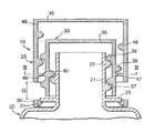
- FIG. 1is a section of a closure according to a first embodiment of the present invention, shown attached to a container and being in a first position;
- FIG. 2shows the closure of FIG. 1 in a second position prior to removal from the container
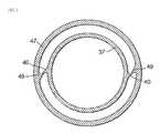
- FIG. 3shows a diagrammatic section along line III-III of FIG. 2 illustrating a ratchet arrangement for locking the closure in the second position;
- FIG. 4shows the closure of FIG. 3 following removal from the container
- FIG. 5shows the closure of FIG. 4 following re-attachment to the container following first opening
- FIG. 6is a section of a tamper-evident closure according to an alternative embodiment, shown forming part of a tamper-evident arrangement on a container neck and being in a first position;
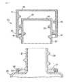
- FIG. 7is a perspective view of a shell forming part of the closure of FIG. 6 ;
- FIG. 8is a perspective view of a ratchet member forming part of the closure of FIG. 6 ;
- FIG. 9is a perspective view of a liner part forming part of the closure of FIG. 6 ;
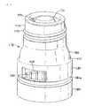
- FIG. 10is a perspective view of a pouring part forming part of the non-return fitment of FIG. 6 ;
- FIG. 11is a perspective section of a basket part forming part of the non-return fitment of FIG. 6 ;
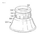
- FIG. 12is a perspective view of a float forming part of the non-return fitment of FIG. 6 ;
- FIG. 13is a perspective view of the neck finish of FIG. 6 ;
- FIG. 14is section of the closure of FIG. 6 with the closure shown in a second position.
- FIG. 1there is shown a tamper-evident closure generally indicated 10 attached to a container generally indicated 20 .
- the container 20includes a neck portion 21 with external screw threads 22 .
- annular retention ring 23At the lower end of the neck 21 is an annular retention ring 23 , the purpose of which is described in more detail below.
- the closurecomprises a first portion 25 and a second portion 30 .
- the first portion 25includes inner 35 and outer 45 parts.
- the inner part 35comprises a disk-shape top plate 36 with a cylindrical skirt 37 depending from its periphery.
- the outer surface of the skirt 37has screw threads 38 for engaging corresponding threads on the outer part 45 .
- the inner surface of the skirt 37has screw threads 39 for engaging corresponding threads 22 on the container 20 .
- the outer surface of the skirt 37also includes two diametrically opposed wedge-shape ratchet members 40 (best shown in FIG. 3 ).
- the outer part 45comprises a disk-shape top plate 46 with a cylindrical skirt 47 depending from its periphery.
- the inner surface of the skirt 47has screw threads 48 for engaging the threads 38 on the inner part 35 .
- the inner surface of the skirtalso includes two dimensionally opposed, wedge-shape ratchet members 49 (best shown in FIG. 3 ).
- the second portion 30comprises an annular tamper-evident band and is connected to the open end of the outer part skirt 47 by frangible bridges 48 .
- a plurality of flaps 31project radially inwardly and upwardly. The flaps 31 are positioned to engage beneath the annular retention ring 23 on the container 20 .
- the outer part 45In order to open the closure 10 the outer part 45 is grasped and turned.
- the tightness of fit between the inner part 35 and the neck portion 21is designed to be greater than that between the inner part 35 and the outer part 45 , which means that there is greater friction. Accordingly when the outer part 45 is initially turned it is the outer part 45 which moves axially upwards relative to the inner part 35 ; the inner part remains stationary.
- the flaps 31prevent the second portion 30 from moving by virtue of their engagement under the retention ring 23 .
- the frangible bridges 48break and the second portion 30 remains in position.
- FIG. 4the closure 10 is shown removed completely from the container neck 21 to allow access to the container 20 .
- the length of the inner part skirt 37is such that it protrudes below the level of the outer part skirt 47 in the second position.
- the skirt 37can be seen through the gap (G).
- the skirt 37could, for example, be brightly coloured or include a message in the area visible through the gap (G) to accentuate the fact that the gap (G) is there and warn of potential tampering.
- FIGS. 6 to 13show an alternative embodiment of the present invention.
- the closure 110forms part of a tamper-evident arrangement for a container 120 having a neck 121 with an associated in-bore non-return fitment generally indicated 100 .
- the components of the tamper-evident arrangementare as follows: the closure 110 comprises a shell 155 , a ratchet part 160 and a liner part 165 ; the non-return fitment 100 comprises a pouring part 175 , a ball 200 , a float valve 186 and a basket part 190 .
- the closure shell 155is shown in FIG. 7 and is a metal closure of the well-known “roll-on pilfer-proof” type.
- the shellcomprises a disk-shape top plate 156 with a side wall 157 depending from its periphery.
- the shell 155includes upper 155 a and lower 155 b sections.
- the shape of the side wall 157is determined at least in part after the shell is applied because a series of rollers and cutters are used to form a frangible line 159 and first 158 a and second 158 b rolled-in regions, as is described in more detail below.
- the ratchet part 160is shown in FIG. 8 and comprises a tubular body part.
- the inner surface of the part 160includes screw threads 161 .
- the inner surfacealso includes a ratchet member 162 for engaging a corresponding notch in the liner part 165 .
- the inner surfacealso includes a ratchet step 163 formed by a band of thicker material at the opposite end of the part 160 to the ratchet member 162 .
- the outer surfaceincludes an annular groove 164 which is used to hold the part 160 in the shell 155 by virtue of a first crimped-in region 158 of the shell 155 (see FIG. 6 ).
- the liner part 165is shown in FIG. 9 and comprises a disk-shape top plate 166 with a cylindrical skirt 167 depending from its periphery.
- the upper part 167 a of the surface of the skirt 167includes screw threads 168 for engaging the threads 161 of the ratchet part.
- the inner surface of the skirt 167includes screw threads 169 (shown in phantom on FIG. 9 ) for engaging corresponding threads on the pouring part 175 .
- Below the thread start of the external screw thread 168is a notch 174 for receiving the ratchet member 162 of the ratchet part 160 .
- Below the thread start of the internal screw thread 169is a ratchet tooth 174 a (see 6 ) for engaging a corresponding tooth 180 a on the outer surface of the pouring part 175 (see FIG. 6 ).
- the top plate 166is surrounded by an annular upturned flap 170 .
- the skirt 167includes an annular extension portion 171 below an annular flange 172 at the lower end of the skirt 167 .
- annular plug band 173depends from the inner surface of the top plate 166 and is adapted to engage in the pouring part 175 .
- the pouring part 175is shown in FIG. 10 and comprises a generally frusto-conical hollow body with an upper thread-bearing portion 176 having external screw threads 177 for engaging the internal screw threads 169 on the liner 165 .
- a dome-shape flow regulator 178Within the thread bearing portion 176 is positioned a dome-shape flow regulator 178 .
- the regulator 178is attached by three axial spokes 179 to the inner wall of the portion 176 to provide a flow path around the regulator 178 .
- a ball chamber 180depends from the portion 176 and is sized to accommodate the ball 200 in such a way that it can move freely.
- the outer surface of the ball chamber 180includes the ratchet tooth 180 a for engaging the ratchet tooth 174 a of the liner part 165 ,
- a basket-retaining part 181depends from the ball chamber 180 .
- the internal bore of the basket-retaining part 181is increased by a step 182 at the bottom of the hall chamber 180 .
- the increased boreis sized to accommodate the basket 190 as described below.
- a neck-engaging part 183depends from the basket retaining part 181 .
- the neck-engaging part 183begins with an external annular groove 184 a which is used to help hold the fitment 175 on the container neck 121 by virtue of the second rolled-in region 158 b of the shell (see FIG. 6 ).
- the internal surface of the part 183includes a plurality of axial ribs 185 for engaging ribs 125 on the container neck 121 , as described below.
- the ribs 185are visible in FIG. 10 through a window 186 in the basket-retaining part.
- An identical windowis present diametrically opposite (not shown).
- the windows 186are present so that a sharp retention edge 184 c can be formed in a molding production process.
- the edge 184 cprovides a very strong connection under the lip 123 of the container neck 121 .
- the basket part 190is shown in FIG. 11 and includes an annular upper part 191 sized so that it has an interference sealing fit within the basket-retaining part 181 of the pouring part 175 .
- the sealis improved with the presence of a bead 192 approximately half way along the outer surface of the part 191 .
- the internal diameter of the part 190decreases at the lower end of the upper part 191 with a curved step 193 and continues to form an annular plug part 194 sized to fit sealingly into the internal bore of the container neck 121 .
- Approximately half way along the external surface of the plug part 194is a bead 195 for improving the seal against the container neck 121 .
- a valve seatcomprising a circular groove 194 extends radially inwardly and connects to a non-return valve comprising an upstanding hoop 195 with the three internal spokes 196 forming three generally triangular orifices 197 .
- an inwardly curved sealing member 198depends at the bottom of the annular upper part 191 . The sealing member 198 can flex upwardly towards the underside of the step 193 and is positioned to seal against the upper surface 122 of the container neck.
- circumferential flange 199extends radially outwards.
- the float valve 186is shown in FIG. 12 and comprises a disk-shape top plate 187 with a cylindrical skirt 188 depending from its periphery.
- the skirt 188is sized so that its open end fits into the groove 194 of the basket part 190 .
- the neck finish 121is shown in FIG. 13 and comprises an upper lip 123 below which is a lower portion 124 of reduced diameter.
- the lower portionhas a plurality of spaced axial ribs 125 around its periphery.
- a shoulderemerges from the lower end of the lower portion 124 .
- the tamper-evident arrangement shown in FIG. 6is assembled as follows.
- the ball 200is placed in the ball chamber 182 .
- the float 186is placed on the basket 190 and sits in the groove 194 .
- the upper part 191 of the basketis pushed into the basket-retaining part 181 of the pouring part 175 ; the insertion extent is limited by the step 182 .
- the liner part 165is screwed onto the pouring part 175 using the corresponding screw threads 169 , 177 .
- the plug part 173enters the inner bore of the thread bearing portion 176 .
- the ratchet part 160is connected to the pouring part by opening the tubular body part at the split line 160 a .
- the part 160is then fitted around the upper part 167 a of the pouring part before allowing the part 160 to close with the threads 161 , 168 now engaged and the lower edge of the ratchet resting on the liner flange 172 .
- the ratchet part 160 , liner part 165 , pouring part 175 , ball 200 , float valve 186 and basket part 190are then added to the container neck 121 by pressing the neck-engaging part 183 of the pouring part 175 over the lip 123 .
- the plug part 192 of the basket 190enters the inner bore of the container neck 121 until the sealing member 198 contacts the upper surface 122 of the container neck 121 and the step 184 b clips under the lip 123 . At this point the ribs 125 , 185 on the neck 121 and pouring part 175 engage to prevent relative rotation.
- the shell 155is now added.
- the shell side wall 157 bis initially straight. Following placement over the rest of the tamper-evident arrangement the side wall is crimped into the groove 164 of the ratchet part and the groove 184 of the pouring part at points 158 a and 158 b respectively.
- a frangible line 159is created approximately half way down the side wall 157 by slitting to leave thin bridges (not shown).
- the upper section 155 a of the shell 155is grasped above the frangible line 159 and twisted.
- the pouring part 175cannot turn by virtue of the ribs 125 , 185 on the container neck 121 and the neck-engaging part 183 .
- the lower section 155 b of the section of shell below the frangible lineis firmly connected to the pouring part by crimped-in region 158 b , and also cannot turn.
- the liner part 165is prevented from turning relative to the pouring part 175 at this stage because of the interaction of the ratchet teeth 174 a , 180 a.
- the upper section 155 a of the shellturns and the frangible line 159 breaks.
- the turning of the upper section 155 aturns the ratchet part 160 by virtue of the firm connection provided by the region 158 a in the groove 164 .
- the ratchet part 160continues to rise in the upper shell section 155 a until the step 163 passes over the flap 170 and the ratchet member 162 enters the notch 174 on the liner part 165 .
- the flap 170prevents the upper-shell section 155 a from moving back down by its engagement with the step 163 and the ratchet member 162 prevents relative rotation between the ratchet part 160 and the liner part 165 . Because the step 163 and flap 170 are located above the respective screw threads, access to this part of the closure is made difficult. Re-setting of the ratchet arrangement is thereby made more difficult.
- a gap (G 1 )is formed in the shell 155 between the upper 155 a and lower 155 b shell sections.
- the gap (G 1 )is unobstructed; there is no obstacle at the point of dislocation to prevent closing of the gap (G 1 ).
- Continued turning of the upper shell section 155 anow turns the liner 165 with respect to the pouring part 175 ; again the pouring part 175 remains stationary.
- the action of twisting the liner part 165 off the pouring part 175may break one or both of the ratchet teeth 174 a , 180 a , and may make a ‘crack’ sound to reinforce the tamper-proof nature of the closure. Therefore the interaction of the ratchet teeth 174 a , 180 a must be strong enough to counter the force of the ratchet part 160 turning relative to the liner part 165 . In particular the interaction must be strong enough to remain intact as the ratchet part step 163 passes over the liner flap 170 . However, the ratchet teeth 174 a , 180 a interaction is such that it can be overcome once the ratchet part 160 and liner part 165 are locked in place.
- the non-return fitment 100of which the pouring part 175 forms part, will be well known to those skilled in the art and its operation will not be described in detail.
- the upper shell section 155 a , the ratchet part 160 and the liner part 165are then removed to expose the pouring part 175 .
- the upper shell section 155 aconstitutes the first portion outer part of the closure.
- the liner 165constitutes the first portion inner part.
- the lower shell section 155 bconstitutes the second portion.
- the ratchet part 160locks the inner and outer parts together.
Landscapes
- Engineering & Computer Science (AREA)
- Mechanical Engineering (AREA)
- Closures For Containers (AREA)
- Cartons (AREA)
- Bag Frames (AREA)
- Tubes (AREA)
- Pharmaceuticals Containing Other Organic And Inorganic Compounds (AREA)
- Medicines That Contain Protein Lipid Enzymes And Other Medicines (AREA)
- Joints Allowing Movement (AREA)
Abstract
Description
Claims (20)
Priority Applications (1)
| Application Number | Priority Date | Filing Date | Title |
|---|---|---|---|
| US13/828,642US9242768B2 (en) | 2003-10-31 | 2013-03-14 | Tamper evident closure |
Applications Claiming Priority (6)
| Application Number | Priority Date | Filing Date | Title |
|---|---|---|---|
| EP03257261.2 | 2003-10-31 | ||
| EP03257261 | 2003-10-31 | ||
| EP03257261 | 2003-10-31 | ||
| PCT/EP2004/012056WO2005049443A1 (en) | 2003-10-31 | 2004-10-26 | A tamper-evident closure |
| US57757506A | 2006-09-05 | 2006-09-05 | |
| US13/828,642US9242768B2 (en) | 2003-10-31 | 2013-03-14 | Tamper evident closure |
Related Parent Applications (3)
| Application Number | Title | Priority Date | Filing Date |
|---|---|---|---|
| PCT/EP2004/012056ContinuationWO2005049443A1 (en) | 2003-10-31 | 2004-10-26 | A tamper-evident closure |
| US10/577,575ContinuationUS8522991B2 (en) | 2003-10-31 | 2004-10-26 | Tamper evident closure |
| US57757506AContinuation | 2003-10-31 | 2006-09-05 |
Publications (2)
| Publication Number | Publication Date |
|---|---|
| US20130206765A1 US20130206765A1 (en) | 2013-08-15 |
| US9242768B2true US9242768B2 (en) | 2016-01-26 |
Family
ID=34610136
Family Applications (2)
| Application Number | Title | Priority Date | Filing Date |
|---|---|---|---|
| US10/577,575Active2028-05-06US8522991B2 (en) | 2003-10-31 | 2004-10-26 | Tamper evident closure |
| US13/828,642Expired - LifetimeUS9242768B2 (en) | 2003-10-31 | 2013-03-14 | Tamper evident closure |
Family Applications Before (1)
| Application Number | Title | Priority Date | Filing Date |
|---|---|---|---|
| US10/577,575Active2028-05-06US8522991B2 (en) | 2003-10-31 | 2004-10-26 | Tamper evident closure |
Country Status (13)
| Country | Link |
|---|---|
| US (2) | US8522991B2 (en) |
| EP (1) | EP1694576B1 (en) |
| AT (1) | ATE387382T1 (en) |
| BR (1) | BRPI0416014B1 (en) |
| DE (1) | DE602004012149T2 (en) |
| ES (1) | ES2302040T3 (en) |
| MX (1) | MXPA06004684A (en) |
| MY (1) | MY137973A (en) |
| PL (1) | PL1694576T3 (en) |
| PT (1) | PT1694576E (en) |
| SI (1) | SI1694576T1 (en) |
| TW (1) | TWI331118B (en) |
| WO (1) | WO2005049443A1 (en) |
Cited By (3)
| Publication number | Priority date | Publication date | Assignee | Title |
|---|---|---|---|---|
| US20220402666A1 (en)* | 2019-11-07 | 2022-12-22 | Aptar Freyung Gmbh | Closure device |
| USD1014251S1 (en) | 2019-06-03 | 2024-02-13 | Berlin Packaging, Llc | Tamper evident closure assembly |
| USD1023755S1 (en) | 2019-06-03 | 2024-04-23 | Berlin Packaging, Llc | Tamper evident closure assembly |
Families Citing this family (51)
| Publication number | Priority date | Publication date | Assignee | Title |
|---|---|---|---|---|
| EP1251076A1 (en)† | 2001-04-20 | 2002-10-23 | Crown Cork & Seal Technologies Corporation | A closure |
| GB0129176D0 (en) | 2001-12-06 | 2002-01-23 | Dca Design Int Ltd | Improvements in and realting to a medicament cartridge assembly |
| MY137973A (en) | 2003-10-31 | 2009-04-30 | Obrist Closures Switzerland | A tamper-evident closure |
| US20080105644A1 (en)* | 2005-04-29 | 2008-05-08 | Douglas Marcus H L | Tamper-Evident Closure |
| GB0608433D0 (en) | 2006-04-28 | 2006-06-07 | Obrist Closures Switzerland | Closure with RFID device |
| ITMI20070520A1 (en)* | 2007-03-15 | 2008-09-16 | Nicola Fabiano | ANTI-BREAKTHROUGH CLOSING DEVICE FOR BOTTLES |
| GB2450940B (en)* | 2007-07-13 | 2011-11-30 | Obrist Closures Switzerland | Tamper-evident closure |
| GB2450939B (en) | 2007-07-13 | 2012-02-01 | Obrist Closures Switzerland | Tamper-Evident closure |
| GB0721330D0 (en) | 2007-10-31 | 2007-12-12 | Obrist Closures Switzerland | Tamper Evident closure |
| ITMI20080343A1 (en)* | 2008-02-29 | 2009-09-01 | Creative Gcl S R L | DECORATIVE ANTI-SCALE CLOSURE |
| GB0806190D0 (en) | 2008-04-04 | 2008-05-14 | Obrist Closures Switzerland | A closure |
| US8286812B2 (en)* | 2008-04-11 | 2012-10-16 | Andrzej Buczkowski | Device and method for irreversibly selecting indicia |
| GB0809058D0 (en)* | 2008-05-19 | 2008-06-25 | Obrist Closures Switzerland | A tamper-evident closure |
| US8413807B2 (en)* | 2009-02-25 | 2013-04-09 | Inducomp Corporation | Ball display case |
| IT1394229B1 (en)* | 2009-04-16 | 2012-06-01 | Tapi S R L | SCREW CAP FOR CONTAINERS FOR LIQUIDS |
| FR2952620B1 (en)* | 2009-11-19 | 2011-12-30 | Valois Sas | FLUID PRODUCT DISPENSER. |
| EP2371733B1 (en)* | 2010-04-01 | 2014-11-12 | Tetra Laval Holdings & Finance S.A. | A closure for a container |
| USD630093S1 (en) | 2010-06-11 | 2011-01-04 | Obrist Closures Switzerland Gmbh | Closure |
| GB201010045D0 (en)* | 2010-06-16 | 2010-07-21 | Obrist Closures Switzerland | A tamper-evident closure |
| ES2512724T3 (en) | 2010-07-22 | 2014-10-24 | Colgate-Palmolive Company | Packaging for a consumer product |
| ES2765984T3 (en) | 2011-05-31 | 2020-06-11 | Carmel Pharma Ab | Tamper resistant lid |
| ITMI20111799A1 (en) | 2011-10-04 | 2013-04-05 | Creative Gcl S R L | TAMPER EVIDENT CLOSURE |
| GB201119311D0 (en)* | 2011-11-08 | 2011-12-21 | Obrist Closures Switzerland | A tamper evident closure |
| GB201201976D0 (en) | 2012-02-03 | 2012-03-21 | Obrist Closures Switzerland | Tamper-evident closure |
| CN102658910B (en)* | 2012-05-25 | 2014-07-30 | 成都天坤包装有限责任公司 | Anti-counterfeiting structure of bottle cap and bottle cap for same |
| EA020845B1 (en) | 2012-06-13 | 2015-02-27 | Дмитрий Иванович ПАХОМОВ | Closure device |
| ITMI20121324A1 (en) | 2012-07-27 | 2014-01-28 | Guala Closures Spa | TAMPER EVIDENT CLOSURE. |
| JP6065454B2 (en)* | 2012-08-16 | 2017-01-25 | 東洋製罐株式会社 | Opening detection composite cap |
| EP2765090B1 (en) | 2013-02-08 | 2016-04-20 | Guala Closures S.p.A. | Tamper evident closure |
| GB201307034D0 (en)* | 2013-04-18 | 2013-05-29 | Obrist Closures Switzerland | Tamper-evident closure |
| EP2821350A1 (en)* | 2013-07-05 | 2015-01-07 | Cia. de Tapones Irrellenables, S.A. | Closure device for bottles with evidence of first opening |
| ITMO20130242A1 (en)* | 2013-08-29 | 2015-03-01 | Ativa | SECURITY CAP FOR CONTAINERS. |
| USD748472S1 (en) | 2013-11-08 | 2016-02-02 | W.L. Gore & Associates Gmbh | Vent |
| GB201401682D0 (en)* | 2014-01-31 | 2014-03-19 | Obrist Closures Switzerland | A tamper-evident closure |
| US9796513B2 (en)* | 2014-10-13 | 2017-10-24 | Sunoco Development, Inc. | Overcap with cutting ring for rigid paper cans |
| MX2018005819A (en) | 2015-11-10 | 2018-09-17 | Obrist Closures Switzerland | Improvements in or relating to a closure for a container neck. |
| ES2783348T3 (en) | 2015-12-02 | 2020-09-17 | Gcl Int Sarl | A tamper-proof closure |
| IT201600080146A1 (en)* | 2016-07-29 | 2018-01-29 | Guala Pack Spa | CLOSURE WITH A GUARANTEE SEAL |
| FR3056197B1 (en)* | 2016-09-22 | 2020-12-25 | Nemera La Verpilliere | REMOVABLE CAP FOR LIQUID DISTRIBUTION DEVICE |
| US10232990B2 (en)* | 2017-01-05 | 2019-03-19 | Compliant Packaging Llc | Child resistant storage container |
| EP3601086B1 (en)* | 2017-03-23 | 2023-02-08 | Aptar Freyung GmbH | Dispensing closure for a fluid container |
| JP7040715B2 (en)* | 2017-10-27 | 2022-03-23 | 阪神化成工業株式会社 | cap |
| CN107804579B (en)* | 2017-11-22 | 2023-12-22 | 吉林大学 | Novel beverage bottle cap sealing mechanism |
| JP2019107386A (en)* | 2017-12-20 | 2019-07-04 | 株式会社フォーエス | Hydrogen permeation apparatus |
| GB2576009A (en) | 2018-08-01 | 2020-02-05 | Obrist Closures Switzerland | A tamper-evident closure |
| JP2021041946A (en)* | 2019-09-09 | 2021-03-18 | きた産業株式会社 | Screw cap |
| FR3103474A1 (en)* | 2019-11-21 | 2021-05-28 | Psa Automobiles Sa | SAFETY SYSTEM FOR OPENING A CONTAINER THROUGH A MOVING CAP |
| USD1028646S1 (en) | 2021-04-30 | 2024-05-28 | Opti-Harvest, Inc. | Canopy unit for light harvesting |
| JP7635094B2 (en) | 2021-07-30 | 2025-02-25 | 株式会社吉野工業所 | Container with cap |
| EP4273064A1 (en)* | 2022-05-02 | 2023-11-08 | Seidel GmbH & Co. KG | Closing cap assembly |
| US20240253867A1 (en)* | 2023-01-30 | 2024-08-01 | Creanova Universal Closures Limited | Juice closure |
Citations (115)
| Publication number | Priority date | Publication date | Assignee | Title |
|---|---|---|---|---|
| US1798151A (en) | 1929-12-16 | 1931-03-31 | Guardian Safety Seal Company | Sealing cap for bottles |
| DE809896C (en) | 1946-09-13 | 1951-08-02 | Albert Gourgues | Airtight infusion pack |
| DE861666C (en) | 1950-12-03 | 1953-01-05 | Erich Ebbinghaus | Automatic closure for tubes and bottles |
| US2858054A (en) | 1955-03-09 | 1958-10-28 | Stuard K Harkrader | Dispensing device |
| US3348718A (en) | 1965-01-20 | 1967-10-24 | Bouchage Mecanique | Bottle closure |
| US3412890A (en) | 1967-12-22 | 1968-11-26 | Clark Mfg Co J L | Hinged container closure |
| US3425578A (en) | 1967-09-05 | 1969-02-04 | Nicoli Owens | Pill container |
| US3455479A (en) | 1966-11-30 | 1969-07-15 | Metal Closures Ltd | Bottle closure having a frangible skirt portion |
| US3603470A (en) | 1970-01-02 | 1971-09-07 | Monsanto Co | Compressible safety closure |
| GB1298084A (en) | 1968-12-31 | 1972-11-29 | Rech S Et D Applic Scient Et M | Capsules and other self-supporting medicinal packaging means |
| US3810556A (en) | 1971-06-25 | 1974-05-14 | Bouchage Mecanique | Tamper-proof easy-opening bottle cap |
| US3820683A (en) | 1972-02-10 | 1974-06-28 | A Jasinski | Spray can safety cap |
| US3871545A (en) | 1973-07-16 | 1975-03-18 | Astra Plastique | Closure devices for containers |
| US3892351A (en) | 1974-07-12 | 1975-07-01 | Procter & Gamble | Container subassembly having a membrane-type closure |
| GB1473482A (en) | 1974-01-25 | 1977-05-11 | Bouchage Mecanique | Closed receptacle provided with a security device |
| GB1484517A (en) | 1974-07-23 | 1977-09-01 | Nova Handels Ag | Child-proof closure |
| US4091949A (en) | 1977-03-14 | 1978-05-30 | Baxter Travenol Laboratories, Inc. | Antibackoff threaded ring closure using ratchet means |
| FR2439139A1 (en) | 1978-10-21 | 1980-05-16 | Kwasny Chem Tech | DOUBLE SAFETY LID FOR CHILDREN |
| US4303171A (en) | 1979-08-03 | 1981-12-01 | Aladdin Industries Pty. Limited | Container closures |
| US4310105A (en) | 1980-04-24 | 1982-01-12 | Sunbeam Plastics Corporation | Child-resistant dispensing closure |
| GB2123392A (en) | 1982-07-10 | 1984-02-01 | Mardon Illingworth | Container sealing devices and method of sealing oontainers |
| GB2136782A (en) | 1983-03-22 | 1984-09-26 | Metal Closures Ltd | Pilferproof closure |
| EP0127943A1 (en) | 1983-05-09 | 1984-12-12 | Johnsen & Jorgensen (Plastics) Limited | Tamper-resistant press-and-turn closure |
| EP0132792A1 (en) | 1983-07-20 | 1985-02-13 | DISPO-Kommerz AG | Water soluble powdery cleaning agent for hard surfaces |
| GB2148235A (en) | 1983-10-20 | 1985-05-30 | Warner Lambert Co | Die pressure moulded capsules |
| US4531649A (en) | 1984-04-23 | 1985-07-30 | Anchor Hocking Corporation | Molded plastic cap with sealing liner |
| GB2158424A (en) | 1984-04-20 | 1985-11-13 | Guala Angelo Spa | Security closure for bottles |
| FR2567106A1 (en) | 1984-07-06 | 1986-01-10 | Laube Werner | Rotating closure for fluid container |
| DE8535205U1 (en) | 1985-12-14 | 1986-02-06 | Vedder & Comp. GmbH, 5750 Menden | Closure |
| US4569464A (en) | 1983-06-22 | 1986-02-11 | Victor Wassilieff | Sealing and distributing device for containers of fluids |
| EP0179498A1 (en) | 1984-10-19 | 1986-04-30 | Lynes Holding S.A. | Method of sealing a container |
| GB2172803A (en) | 1985-03-28 | 1986-10-01 | Stc Plc | Controlled delivery device |
| US4637519A (en) | 1985-09-03 | 1987-01-20 | Sun Coast Plastics, Inc. | Two part closure |
| FR2591571A1 (en) | 1985-12-14 | 1987-06-19 | Vedder & Co Gmbh | Closure |
| DE3605963A1 (en) | 1986-02-25 | 1987-08-27 | Deussen Stella Kg | Safety container closure |
| EP0236136A2 (en) | 1986-03-07 | 1987-09-09 | Unilever Plc | Product for dispensing treatment agents in a washing or dishwashing machine |
| US4697719A (en) | 1986-11-03 | 1987-10-06 | Allen Tool Company, Inc. | Foil-lid combination for containers |
| US4790442A (en) | 1988-04-22 | 1988-12-13 | Sunbeam Plastics Corporation | Child resistant closure |
| EP0306670A2 (en) | 1987-09-09 | 1989-03-15 | Jacob Berg GmbH & Co. KG | Plastic closure for a plastic container |
| US4838441A (en) | 1988-04-11 | 1989-06-13 | Chernack Milton P | Child resistant closure |
| EP0337568A2 (en) | 1988-04-11 | 1989-10-18 | Colgate-Palmolive Company | Detersive article |
| GB2222821A (en) | 1988-09-20 | 1990-03-21 | Massmould Holdings | Closures for releasably sealing containers |
| US4941592A (en) | 1989-06-19 | 1990-07-17 | Seaquist Closures | Hinged dispensing closure with a tamper-evident seal |
| US4942970A (en) | 1988-07-14 | 1990-07-24 | Vivian Jay | Hermetically sealed canister |
| EP0414462A2 (en) | 1989-08-23 | 1991-02-27 | Unilever Plc | Laundry treatment product |
| EP0425391A1 (en) | 1989-10-27 | 1991-05-02 | Institut Des Substances Vegetales | Compositions comprising juice and plant protoplasts, process to prepare them and their application, especially in the field of phytotherapy |
| GB2264110A (en) | 1991-03-07 | 1993-08-18 | Northern Eng & Plastics | Resealable bottle cap with push-pull closure |
| WO1994007470A1 (en) | 1992-09-30 | 1994-04-14 | Pfizer Inc. | Article containing a core and a coating having a non constant thickness |
| EP0593952A1 (en) | 1992-10-17 | 1994-04-27 | DISPO-Kommerz AG | Product for releasing treatment agents into the wash liquid of an automatic washing or dishwashing machine |
| US5332113A (en) | 1989-11-30 | 1994-07-26 | Elan Pharmaceutical Research Corporation | Cap assembly |
| EP0619243A1 (en) | 1993-04-08 | 1994-10-12 | Manufacture Lyonnaise de Bouchage Société Anonyme | Anti-theft device for containers provided with a capping or an overcapping means |
| US5427260A (en) | 1993-07-28 | 1995-06-27 | Aptargroup, Inc. | Closure with insertable tamper indicator |
| US5445824A (en) | 1991-12-14 | 1995-08-29 | Marine Bio Co., Ltd. | Physiological activating material extracted from coral sand |
| EP0688723A1 (en) | 1994-06-22 | 1995-12-27 | Japan Crown Cork Co. Ltd. | Plastic container closure and method of producing the same |
| US5588545A (en) | 1991-09-23 | 1996-12-31 | Beeson And Sons Limited | Child-resistant and elderly friendly closure for containers |
| US5603422A (en) | 1992-03-06 | 1997-02-18 | Herrmann; Ernst | Plastic safety closure for bottles simulating the appearance of a traditional cork-type wine bottle closure |
| GB2311283A (en) | 1996-03-19 | 1997-09-24 | Lawson Mardon | Cap for a container |
| US5683016A (en) | 1993-05-06 | 1997-11-04 | Taplast Srl | Molded plastic cap for dispensing liquids |
| US5755348A (en) | 1990-08-09 | 1998-05-26 | Portola Packaging, Inc. | Snap-on, screw-off cap and container neck |
| US5819965A (en) | 1992-11-13 | 1998-10-13 | Beeson And Sons Limited | Tamper evident ring for a container closure |
| JPH10338251A (en) | 1997-06-02 | 1998-12-22 | Kitano Seisaku Kk | Cap with hinge |
| WO1999057031A1 (en) | 1998-04-30 | 1999-11-11 | Creanova Ag | Safeguarding mechanism |
| US6036036A (en) | 1995-06-28 | 2000-03-14 | The Procter & Gamble Company | Adult friendly child-resistant package |
| WO2000026878A1 (en) | 1998-10-29 | 2000-05-11 | Sensormatic Electronics Corporation | Cap with integrated eas marker |
| US6095375A (en) | 1998-09-15 | 2000-08-01 | Portola Packaging, Inc. | Dust cover attachment for push-pull cap |
| JP2000229651A (en) | 1999-02-12 | 2000-08-22 | Runa Kasei Kk | Cap of container for beverage |
| WO2000066451A1 (en) | 1999-04-30 | 2000-11-09 | Audus Noble Ltd. | Tamper-evident container |
| DE20019797U1 (en) | 2000-11-21 | 2001-04-05 | MALA Verschlußsysteme GmbH, 36448 Schweina | Sealing cap |
| GB2355269A (en) | 2000-08-08 | 2001-04-18 | Procter & Gamble | Liquid cleaning composition |
| EP1101707A1 (en) | 1999-11-15 | 2001-05-23 | Sonoco Development, Inc. | Resealing overcap for a cylindrical container |
| WO2001036290A1 (en) | 1999-11-17 | 2001-05-25 | Reckitt Benckiser (Uk) Limited | Injection-moulded water-soluble container |
| GB2356842A (en) | 1999-11-17 | 2001-06-06 | Aquasol Ltd | Injection-moulded capsules |
| US6269986B1 (en) | 2000-06-20 | 2001-08-07 | Seaquist Closures Foreign, Inc. | Dispensing closure with tamper evident lid panel |
| WO2001083668A1 (en) | 2000-04-28 | 2001-11-08 | The Procter & Gamble Company | Pouched compositions |
| US6328174B1 (en)* | 1996-11-25 | 2001-12-11 | Diseno Industrial Mago. S.L. | Sealed closure cap |
| EP1161382A1 (en) | 1999-03-17 | 2001-12-12 | Unilever Plc | Water soluble package |
| WO2002044047A1 (en) | 2000-12-01 | 2002-06-06 | Jerzy Machnicki | A bottle closure with markings |
| US20020125249A1 (en) | 1997-06-04 | 2002-09-12 | Ian Baird-Smith | An open ended container closure including a flexible membrane and a rigid cap |
| WO2002085730A1 (en) | 2001-04-20 | 2002-10-31 | Crown Cork & Seal Technologies Corporation | A closure |
| GB2375516A (en) | 2001-05-17 | 2002-11-20 | Reckitt Benckiser | Water soluble injection moulded container |
| US6484879B2 (en) | 1997-04-07 | 2002-11-26 | Syngenta Crop Protection, Inc. | Water soluble packaging system and method |
| WO2002096771A1 (en) | 2001-05-25 | 2002-12-05 | Daniel Montgomery & Son Limited | Tamper-evident device |
| EP1266839A2 (en) | 2001-06-13 | 2002-12-18 | Portola Packaging Limited | Pull-tab |
| EP1283175A2 (en) | 2001-07-31 | 2003-02-12 | Bericap | Device for closing a container and removing a fluid product |
| WO2003016165A1 (en) | 2001-08-16 | 2003-02-27 | Warner-Lambert Company Llc | Water soluble packaging |
| WO2003016162A1 (en) | 2001-08-17 | 2003-02-27 | Seaquist Closures Foreign, Inc. | Tamper-evident closure |
| JP2003160162A (en) | 2001-11-27 | 2003-06-03 | Yoshino Kogyosho Co Ltd | Cap |
| US6685046B2 (en) | 2000-12-01 | 2004-02-03 | Takashi Ogino | Food preservative container |
| US6688501B2 (en) | 2000-06-09 | 2004-02-10 | Seaquist Closures Foreign, Inc. | Dispensing closure for spreadable product |
| US20040026420A1 (en) | 2002-08-01 | 2004-02-12 | Huhtamaki Consumer Packaging, Inc. | Rotatable dispenser closure for use with a container |
| WO2004011347A3 (en) | 2002-07-31 | 2004-04-15 | Montgomery Daniel & Son Ltd | Liquid container closure assembly |
| US6727215B2 (en) | 2000-07-24 | 2004-04-27 | The Procter & Gamble Company | Articles containing enclosed compositions |
| US20040143505A1 (en) | 2002-10-16 | 2004-07-22 | Aram Kovach | Method for tracking and disposition of articles |
| US6866164B2 (en) | 2002-04-26 | 2005-03-15 | Rexam Medical Packaging Inc. | Child resistant dispenser |
| US6880729B2 (en) | 2002-07-12 | 2005-04-19 | Stull Technologies | Secure lock closure |
| WO2005024745A3 (en) | 2003-09-08 | 2005-05-12 | Frances M Claessens | Bottle cap |
| WO2005049443A1 (en) | 2003-10-31 | 2005-06-02 | Crown Packaging Technology Inc | A tamper-evident closure |
| US20050133475A1 (en) | 2001-08-30 | 2005-06-23 | Takayuki Goto | Safety cap and container with safety cap |
| US20050205607A1 (en) | 2004-03-22 | 2005-09-22 | Valentin Hierzer | Child-resistant flip-top closure |
| WO2006000532A1 (en) | 2004-06-23 | 2006-01-05 | Obrist Closures Switzerland Gmbh | Wadless closure |
| WO2006003168A1 (en) | 2004-06-30 | 2006-01-12 | Obrist Closures Switzerland Gmbh | Dispensing closure |
| US20060011573A1 (en) | 2004-07-16 | 2006-01-19 | Herald Coy M | Tamper-indicating dispensing closure |
| WO2006008285A1 (en) | 2004-07-16 | 2006-01-26 | Obrist Closures Switzerland Gmbh | Valve |
| US20060043052A1 (en) | 2004-08-25 | 2006-03-02 | Robert Lin | Bottle closure |
| US20060077062A1 (en) | 2004-10-01 | 2006-04-13 | Gary Andrechak | Radio frequency identification tags for digital storage discs |
| EP1663809A1 (en) | 2002-07-03 | 2006-06-07 | CROWN Packaging Technology, Inc. | Water soluble container |
| US7125828B2 (en) | 2000-11-27 | 2006-10-24 | The Procter & Gamble Company | Detergent products, methods and manufacture |
| WO2006117505A1 (en) | 2005-04-29 | 2006-11-09 | Obrist Closures Switzerland Gmbh | A tamper-evident closure |
| GB2430667A (en) | 2005-09-30 | 2007-04-04 | Raoul Eugenio Fontana | A tamper evident closure |
| US7204383B2 (en) | 2004-06-16 | 2007-04-17 | Jumper Enterprise Co., Ltd. | Seal container |
| GB2432153B (en) | 2004-06-23 | 2007-11-07 | Obrist Closures Switzerland | Wadless closure |
| WO2007125292A3 (en) | 2006-04-28 | 2007-12-21 | Obrist Closures Switzerland | Closure with rfid device |
| WO2009056829A1 (en) | 2007-10-31 | 2009-05-07 | Obrist Closures Switzerland Gmbh | Tamper evident closure |
| US20110259844A1 (en) | 2007-07-13 | 2011-10-27 | Steven Andrew Skelton | Tamper-evident closure |
| US8453856B2 (en) | 2007-07-13 | 2013-06-04 | Obrist Closures Switzerland Gmbh | Tamper-evident closure |
Family Cites Families (3)
| Publication number | Priority date | Publication date | Assignee | Title |
|---|---|---|---|---|
| GB2183897B (en)* | 1985-10-30 | 1990-07-11 | Perkin Elmer Corp | Ionization detectors for gas chromatography |
| US4744480A (en) | 1985-12-19 | 1988-05-17 | The West Company | Tamper-evident container-closure |
| CA1282465C (en)* | 1986-02-27 | 1991-04-02 | Hitachi, Ltd. | Phase-locked loop |
- 2004
- 2004-10-25MYMYPI20044392Apatent/MY137973A/enunknown
- 2004-10-26BRBRPI0416014Apatent/BRPI0416014B1/enactiveIP Right Grant
- 2004-10-26ATAT04790841Tpatent/ATE387382T1/ennot_activeIP Right Cessation
- 2004-10-26SISI200430703Tpatent/SI1694576T1/enunknown
- 2004-10-26EPEP04790841Apatent/EP1694576B1/ennot_activeExpired - Lifetime
- 2004-10-26PLPL04790841Tpatent/PL1694576T3/enunknown
- 2004-10-26TWTW093132373Apatent/TWI331118B/ennot_activeIP Right Cessation
- 2004-10-26ESES04790841Tpatent/ES2302040T3/ennot_activeExpired - Lifetime
- 2004-10-26PTPT04790841Tpatent/PT1694576E/enunknown
- 2004-10-26WOPCT/EP2004/012056patent/WO2005049443A1/enactiveIP Right Grant
- 2004-10-26MXMXPA06004684Apatent/MXPA06004684A/enactiveIP Right Grant
- 2004-10-26DEDE602004012149Tpatent/DE602004012149T2/ennot_activeExpired - Lifetime
- 2004-10-26USUS10/577,575patent/US8522991B2/enactiveActive
- 2013
- 2013-03-14USUS13/828,642patent/US9242768B2/ennot_activeExpired - Lifetime
Patent Citations (128)
| Publication number | Priority date | Publication date | Assignee | Title |
|---|---|---|---|---|
| US1798151A (en) | 1929-12-16 | 1931-03-31 | Guardian Safety Seal Company | Sealing cap for bottles |
| DE809896C (en) | 1946-09-13 | 1951-08-02 | Albert Gourgues | Airtight infusion pack |
| DE861666C (en) | 1950-12-03 | 1953-01-05 | Erich Ebbinghaus | Automatic closure for tubes and bottles |
| US2858054A (en) | 1955-03-09 | 1958-10-28 | Stuard K Harkrader | Dispensing device |
| US3348718A (en) | 1965-01-20 | 1967-10-24 | Bouchage Mecanique | Bottle closure |
| US3455479A (en) | 1966-11-30 | 1969-07-15 | Metal Closures Ltd | Bottle closure having a frangible skirt portion |
| US3425578A (en) | 1967-09-05 | 1969-02-04 | Nicoli Owens | Pill container |
| US3412890A (en) | 1967-12-22 | 1968-11-26 | Clark Mfg Co J L | Hinged container closure |
| GB1298084A (en) | 1968-12-31 | 1972-11-29 | Rech S Et D Applic Scient Et M | Capsules and other self-supporting medicinal packaging means |
| US3603470A (en) | 1970-01-02 | 1971-09-07 | Monsanto Co | Compressible safety closure |
| US3810556A (en) | 1971-06-25 | 1974-05-14 | Bouchage Mecanique | Tamper-proof easy-opening bottle cap |
| US3820683A (en) | 1972-02-10 | 1974-06-28 | A Jasinski | Spray can safety cap |
| US3871545A (en) | 1973-07-16 | 1975-03-18 | Astra Plastique | Closure devices for containers |
| GB1473482A (en) | 1974-01-25 | 1977-05-11 | Bouchage Mecanique | Closed receptacle provided with a security device |
| US3892351A (en) | 1974-07-12 | 1975-07-01 | Procter & Gamble | Container subassembly having a membrane-type closure |
| GB1484517A (en) | 1974-07-23 | 1977-09-01 | Nova Handels Ag | Child-proof closure |
| US4091949A (en) | 1977-03-14 | 1978-05-30 | Baxter Travenol Laboratories, Inc. | Antibackoff threaded ring closure using ratchet means |
| FR2439139A1 (en) | 1978-10-21 | 1980-05-16 | Kwasny Chem Tech | DOUBLE SAFETY LID FOR CHILDREN |
| US4303171A (en) | 1979-08-03 | 1981-12-01 | Aladdin Industries Pty. Limited | Container closures |
| US4310105A (en) | 1980-04-24 | 1982-01-12 | Sunbeam Plastics Corporation | Child-resistant dispensing closure |
| GB2123392A (en) | 1982-07-10 | 1984-02-01 | Mardon Illingworth | Container sealing devices and method of sealing oontainers |
| GB2136782A (en) | 1983-03-22 | 1984-09-26 | Metal Closures Ltd | Pilferproof closure |
| EP0127943A1 (en) | 1983-05-09 | 1984-12-12 | Johnsen & Jorgensen (Plastics) Limited | Tamper-resistant press-and-turn closure |
| US4569464A (en) | 1983-06-22 | 1986-02-11 | Victor Wassilieff | Sealing and distributing device for containers of fluids |
| EP0132792A1 (en) | 1983-07-20 | 1985-02-13 | DISPO-Kommerz AG | Water soluble powdery cleaning agent for hard surfaces |
| GB2148235A (en) | 1983-10-20 | 1985-05-30 | Warner Lambert Co | Die pressure moulded capsules |
| GB2158424A (en) | 1984-04-20 | 1985-11-13 | Guala Angelo Spa | Security closure for bottles |
| US4531649A (en) | 1984-04-23 | 1985-07-30 | Anchor Hocking Corporation | Molded plastic cap with sealing liner |
| FR2567106A1 (en) | 1984-07-06 | 1986-01-10 | Laube Werner | Rotating closure for fluid container |
| EP0179498A1 (en) | 1984-10-19 | 1986-04-30 | Lynes Holding S.A. | Method of sealing a container |
| GB2172803A (en) | 1985-03-28 | 1986-10-01 | Stc Plc | Controlled delivery device |
| US4637519A (en) | 1985-09-03 | 1987-01-20 | Sun Coast Plastics, Inc. | Two part closure |
| FR2591571A1 (en) | 1985-12-14 | 1987-06-19 | Vedder & Co Gmbh | Closure |
| DE8535205U1 (en) | 1985-12-14 | 1986-02-06 | Vedder & Comp. GmbH, 5750 Menden | Closure |
| DE3605963A1 (en) | 1986-02-25 | 1987-08-27 | Deussen Stella Kg | Safety container closure |
| EP0236136A2 (en) | 1986-03-07 | 1987-09-09 | Unilever Plc | Product for dispensing treatment agents in a washing or dishwashing machine |
| US4697719A (en) | 1986-11-03 | 1987-10-06 | Allen Tool Company, Inc. | Foil-lid combination for containers |
| US5004126A (en) | 1987-09-09 | 1991-04-02 | Konrad Klesius | Plastic closure for a plastic container |
| EP0306670A2 (en) | 1987-09-09 | 1989-03-15 | Jacob Berg GmbH & Co. KG | Plastic closure for a plastic container |
| US4838441A (en) | 1988-04-11 | 1989-06-13 | Chernack Milton P | Child resistant closure |
| EP0337568A2 (en) | 1988-04-11 | 1989-10-18 | Colgate-Palmolive Company | Detersive article |
| US4790442A (en) | 1988-04-22 | 1988-12-13 | Sunbeam Plastics Corporation | Child resistant closure |
| US4942970A (en) | 1988-07-14 | 1990-07-24 | Vivian Jay | Hermetically sealed canister |
| GB2222821A (en) | 1988-09-20 | 1990-03-21 | Massmould Holdings | Closures for releasably sealing containers |
| US4941592A (en) | 1989-06-19 | 1990-07-17 | Seaquist Closures | Hinged dispensing closure with a tamper-evident seal |
| EP0414462A2 (en) | 1989-08-23 | 1991-02-27 | Unilever Plc | Laundry treatment product |
| EP0425391A1 (en) | 1989-10-27 | 1991-05-02 | Institut Des Substances Vegetales | Compositions comprising juice and plant protoplasts, process to prepare them and their application, especially in the field of phytotherapy |
| US5332113A (en) | 1989-11-30 | 1994-07-26 | Elan Pharmaceutical Research Corporation | Cap assembly |
| US5755348A (en) | 1990-08-09 | 1998-05-26 | Portola Packaging, Inc. | Snap-on, screw-off cap and container neck |
| GB2264110A (en) | 1991-03-07 | 1993-08-18 | Northern Eng & Plastics | Resealable bottle cap with push-pull closure |
| US5588545A (en) | 1991-09-23 | 1996-12-31 | Beeson And Sons Limited | Child-resistant and elderly friendly closure for containers |
| US5445824A (en) | 1991-12-14 | 1995-08-29 | Marine Bio Co., Ltd. | Physiological activating material extracted from coral sand |
| US5603422A (en) | 1992-03-06 | 1997-02-18 | Herrmann; Ernst | Plastic safety closure for bottles simulating the appearance of a traditional cork-type wine bottle closure |
| WO1994007470A1 (en) | 1992-09-30 | 1994-04-14 | Pfizer Inc. | Article containing a core and a coating having a non constant thickness |
| EP0593952A1 (en) | 1992-10-17 | 1994-04-27 | DISPO-Kommerz AG | Product for releasing treatment agents into the wash liquid of an automatic washing or dishwashing machine |
| US5819965A (en) | 1992-11-13 | 1998-10-13 | Beeson And Sons Limited | Tamper evident ring for a container closure |
| EP0619243A1 (en) | 1993-04-08 | 1994-10-12 | Manufacture Lyonnaise de Bouchage Société Anonyme | Anti-theft device for containers provided with a capping or an overcapping means |
| US5683016A (en) | 1993-05-06 | 1997-11-04 | Taplast Srl | Molded plastic cap for dispensing liquids |
| US5427260A (en) | 1993-07-28 | 1995-06-27 | Aptargroup, Inc. | Closure with insertable tamper indicator |
| EP0688723A1 (en) | 1994-06-22 | 1995-12-27 | Japan Crown Cork Co. Ltd. | Plastic container closure and method of producing the same |
| US6036036A (en) | 1995-06-28 | 2000-03-14 | The Procter & Gamble Company | Adult friendly child-resistant package |
| GB2311283A (en) | 1996-03-19 | 1997-09-24 | Lawson Mardon | Cap for a container |
| US6328174B1 (en)* | 1996-11-25 | 2001-12-11 | Diseno Industrial Mago. S.L. | Sealed closure cap |
| US6484879B2 (en) | 1997-04-07 | 2002-11-26 | Syngenta Crop Protection, Inc. | Water soluble packaging system and method |
| JPH10338251A (en) | 1997-06-02 | 1998-12-22 | Kitano Seisaku Kk | Cap with hinge |
| US20020125249A1 (en) | 1997-06-04 | 2002-09-12 | Ian Baird-Smith | An open ended container closure including a flexible membrane and a rigid cap |
| WO1999057031A1 (en) | 1998-04-30 | 1999-11-11 | Creanova Ag | Safeguarding mechanism |
| US6095375A (en) | 1998-09-15 | 2000-08-01 | Portola Packaging, Inc. | Dust cover attachment for push-pull cap |
| WO2000026878A1 (en) | 1998-10-29 | 2000-05-11 | Sensormatic Electronics Corporation | Cap with integrated eas marker |
| JP2000229651A (en) | 1999-02-12 | 2000-08-22 | Runa Kasei Kk | Cap of container for beverage |
| EP1161382A1 (en) | 1999-03-17 | 2001-12-12 | Unilever Plc | Water soluble package |
| WO2000066451A1 (en) | 1999-04-30 | 2000-11-09 | Audus Noble Ltd. | Tamper-evident container |
| EP1101707A1 (en) | 1999-11-15 | 2001-05-23 | Sonoco Development, Inc. | Resealing overcap for a cylindrical container |
| WO2001036290A1 (en) | 1999-11-17 | 2001-05-25 | Reckitt Benckiser (Uk) Limited | Injection-moulded water-soluble container |
| GB2356842A (en) | 1999-11-17 | 2001-06-06 | Aquasol Ltd | Injection-moulded capsules |
| WO2001083668A1 (en) | 2000-04-28 | 2001-11-08 | The Procter & Gamble Company | Pouched compositions |
| US6688501B2 (en) | 2000-06-09 | 2004-02-10 | Seaquist Closures Foreign, Inc. | Dispensing closure for spreadable product |
| US6269986B1 (en) | 2000-06-20 | 2001-08-07 | Seaquist Closures Foreign, Inc. | Dispensing closure with tamper evident lid panel |
| US6727215B2 (en) | 2000-07-24 | 2004-04-27 | The Procter & Gamble Company | Articles containing enclosed compositions |
| GB2355269A (en) | 2000-08-08 | 2001-04-18 | Procter & Gamble | Liquid cleaning composition |
| US6683038B2 (en) | 2000-08-08 | 2004-01-27 | The Procter & Gamble Company | Liquid composition comprising polyalkoxylated polyamines or polyimines |
| DE20019797U1 (en) | 2000-11-21 | 2001-04-05 | MALA Verschlußsysteme GmbH, 36448 Schweina | Sealing cap |
| US7125828B2 (en) | 2000-11-27 | 2006-10-24 | The Procter & Gamble Company | Detergent products, methods and manufacture |
| WO2002044047A1 (en) | 2000-12-01 | 2002-06-06 | Jerzy Machnicki | A bottle closure with markings |
| US6685046B2 (en) | 2000-12-01 | 2004-02-03 | Takashi Ogino | Food preservative container |
| WO2002085730A1 (en) | 2001-04-20 | 2002-10-31 | Crown Cork & Seal Technologies Corporation | A closure |
| US7121419B2 (en) | 2001-04-20 | 2006-10-17 | Crown Obrist Gmbh | Closure |
| GB2375516A (en) | 2001-05-17 | 2002-11-20 | Reckitt Benckiser | Water soluble injection moulded container |
| WO2002096771A1 (en) | 2001-05-25 | 2002-12-05 | Daniel Montgomery & Son Limited | Tamper-evident device |
| EP1266839A2 (en) | 2001-06-13 | 2002-12-18 | Portola Packaging Limited | Pull-tab |
| EP1283175A2 (en) | 2001-07-31 | 2003-02-12 | Bericap | Device for closing a container and removing a fluid product |
| WO2003016165A1 (en) | 2001-08-16 | 2003-02-27 | Warner-Lambert Company Llc | Water soluble packaging |
| WO2003016162A1 (en) | 2001-08-17 | 2003-02-27 | Seaquist Closures Foreign, Inc. | Tamper-evident closure |
| US20050133475A1 (en) | 2001-08-30 | 2005-06-23 | Takayuki Goto | Safety cap and container with safety cap |
| JP2003160162A (en) | 2001-11-27 | 2003-06-03 | Yoshino Kogyosho Co Ltd | Cap |
| US6866164B2 (en) | 2002-04-26 | 2005-03-15 | Rexam Medical Packaging Inc. | Child resistant dispenser |
| EP1663809A1 (en) | 2002-07-03 | 2006-06-07 | CROWN Packaging Technology, Inc. | Water soluble container |
| US20060124646A1 (en) | 2002-07-03 | 2006-06-15 | Bernard Guglielmini | Water-soluble container |
| US6880729B2 (en) | 2002-07-12 | 2005-04-19 | Stull Technologies | Secure lock closure |
| WO2004011347A3 (en) | 2002-07-31 | 2004-04-15 | Montgomery Daniel & Son Ltd | Liquid container closure assembly |
| US20040026420A1 (en) | 2002-08-01 | 2004-02-12 | Huhtamaki Consumer Packaging, Inc. | Rotatable dispenser closure for use with a container |
| US20040143505A1 (en) | 2002-10-16 | 2004-07-22 | Aram Kovach | Method for tracking and disposition of articles |
| WO2005024745A3 (en) | 2003-09-08 | 2005-05-12 | Frances M Claessens | Bottle cap |
| EP1694576A1 (en) | 2003-10-31 | 2006-08-30 | Crown Packaging Technology Inc | A tamper-evident closure |
| US8522991B2 (en)* | 2003-10-31 | 2013-09-03 | Obrist Closures Switzerland Gmbh | Tamper evident closure |
| US20070090110A1 (en) | 2003-10-31 | 2007-04-26 | Skelton Steven A | Tamper evident closure |
| WO2005049443A1 (en) | 2003-10-31 | 2005-06-02 | Crown Packaging Technology Inc | A tamper-evident closure |
| US20050205607A1 (en) | 2004-03-22 | 2005-09-22 | Valentin Hierzer | Child-resistant flip-top closure |
| US7204383B2 (en) | 2004-06-16 | 2007-04-17 | Jumper Enterprise Co., Ltd. | Seal container |
| US20080190880A1 (en) | 2004-06-23 | 2008-08-14 | Obrist Closures Switzerland Gmbh | Wadless Closure |
| GB2415426B (en) | 2004-06-23 | 2007-05-09 | Crown Packaging Technology Inc | Wadless closure |
| WO2006000532A1 (en) | 2004-06-23 | 2006-01-05 | Obrist Closures Switzerland Gmbh | Wadless closure |
| GB2432153B (en) | 2004-06-23 | 2007-11-07 | Obrist Closures Switzerland | Wadless closure |
| WO2006003168A1 (en) | 2004-06-30 | 2006-01-12 | Obrist Closures Switzerland Gmbh | Dispensing closure |
| EP1786698A1 (en) | 2004-06-30 | 2007-05-23 | Obrist Closures Switzerland GmbH | Dispensing closure |
| US20080277613A1 (en) | 2004-07-16 | 2008-11-13 | Roemerstrasse 83 | Valve |
| US20060011573A1 (en) | 2004-07-16 | 2006-01-19 | Herald Coy M | Tamper-indicating dispensing closure |
| WO2006020059A3 (en) | 2004-07-16 | 2007-03-29 | Alcoa Closure Systems Int Inc | Tamper-indicating dispensing closure |
| WO2006008285A1 (en) | 2004-07-16 | 2006-01-26 | Obrist Closures Switzerland Gmbh | Valve |
| US20060043052A1 (en) | 2004-08-25 | 2006-03-02 | Robert Lin | Bottle closure |
| US20060077062A1 (en) | 2004-10-01 | 2006-04-13 | Gary Andrechak | Radio frequency identification tags for digital storage discs |
| WO2006117505A1 (en) | 2005-04-29 | 2006-11-09 | Obrist Closures Switzerland Gmbh | A tamper-evident closure |
| GB2430667A (en) | 2005-09-30 | 2007-04-04 | Raoul Eugenio Fontana | A tamper evident closure |
| WO2007125292A3 (en) | 2006-04-28 | 2007-12-21 | Obrist Closures Switzerland | Closure with rfid device |
| US20090173007A1 (en) | 2006-04-28 | 2009-07-09 | Obrist Closures Switzerland Gmbh | Closure with rfid device |
| US20110259844A1 (en) | 2007-07-13 | 2011-10-27 | Steven Andrew Skelton | Tamper-evident closure |
| US8453856B2 (en) | 2007-07-13 | 2013-06-04 | Obrist Closures Switzerland Gmbh | Tamper-evident closure |
| WO2009056829A1 (en) | 2007-10-31 | 2009-05-07 | Obrist Closures Switzerland Gmbh | Tamper evident closure |
Non-Patent Citations (4)
| Title |
|---|
| EP 1 663 809 B1 Documents related to EP Opposition (EP Patent Granted)-8 pages. |
| International Search Report dated Feb. 27, 2008; UK Application No. GB 0721330.9; 4 pages. |
| Serial No. PCT/EP2003/07798, mailed Oct. 15, 2004, International Search Report and Written Opinion of the International Searching Authority, 5 pages. |
| Serial No. PCT/EP2005/053441, completed Dec. 1, 2005, International Search Report and Written Opinion of the International Searching Authority, 5 pages. |
Cited By (4)
| Publication number | Priority date | Publication date | Assignee | Title |
|---|---|---|---|---|
| USD1014251S1 (en) | 2019-06-03 | 2024-02-13 | Berlin Packaging, Llc | Tamper evident closure assembly |
| USD1023755S1 (en) | 2019-06-03 | 2024-04-23 | Berlin Packaging, Llc | Tamper evident closure assembly |
| US20220402666A1 (en)* | 2019-11-07 | 2022-12-22 | Aptar Freyung Gmbh | Closure device |
| US12012265B2 (en)* | 2019-11-07 | 2024-06-18 | Aptar Freyung Gmbh | Closure device |
Also Published As
| Publication number | Publication date |
|---|---|
| MY137973A (en) | 2009-04-30 |
| US20070090110A1 (en) | 2007-04-26 |
| EP1694576B1 (en) | 2008-02-27 |
| US8522991B2 (en) | 2013-09-03 |
| DE602004012149D1 (en) | 2008-04-10 |
| US20130206765A1 (en) | 2013-08-15 |
| BRPI0416014B1 (en) | 2016-08-23 |
| TW200519000A (en) | 2005-06-16 |
| ES2302040T3 (en) | 2008-07-01 |
| DE602004012149T2 (en) | 2009-03-12 |
| HK1094438A1 (en) | 2007-03-30 |
| BRPI0416014A (en) | 2007-01-02 |
| EP1694576A1 (en) | 2006-08-30 |
| TWI331118B (en) | 2010-10-01 |
| PL1694576T3 (en) | 2008-07-31 |
| MXPA06004684A (en) | 2006-12-14 |
| PT1694576E (en) | 2008-05-27 |
| ATE387382T1 (en) | 2008-03-15 |
| SI1694576T1 (en) | 2008-08-31 |
| WO2005049443A1 (en) | 2005-06-02 |
Similar Documents
| Publication | Publication Date | Title |
|---|---|---|
| US9242768B2 (en) | Tamper evident closure | |
| EP2173633B1 (en) | Tamper-evident closure | |
| US4460100A (en) | Removable resistant container cap and neck assembly | |
| EP1874649B1 (en) | A tamper-evident closure | |
| EP2178771B1 (en) | Tamper-evident closure | |
| US4402418A (en) | Tamperproof closure | |
| US4196818A (en) | Closures for containers | |
| US4709823A (en) | Tamper evident bottle or package closure | |
| CN103153804B (en) | The closure member in the display Kaifeng of improving and packaging | |
| NZ208563A (en) | Tamper-evident closure cap | |
| EP2776335B1 (en) | A tamper evident closure | |
| US10669083B2 (en) | Tamper-evident closure | |
| US4570825A (en) | Tamper-evident cap construction | |
| EP0670271B2 (en) | Bottle closure device with guarantee collar and antirefill valve | |
| WO2009141581A1 (en) | A tamper-evident closure | |
| US5413235A (en) | Tamper-evident closure | |
| US20070158295A1 (en) | Tamper-evidencing container and closure structures | |
| WO2011157978A1 (en) | A tamper-evident closure | |
| HK1094438B (en) | A tamper-evident closure | |
| HK1139113B (en) | Tamper-evident closure | |
| HK1139112B (en) | Tamper-evident closure |
Legal Events
| Date | Code | Title | Description |
|---|---|---|---|
| AS | Assignment | Owner name:CROWN PACKAGING UK PLC, UNITED KINGDOM Free format text:ASSIGNMENT OF ASSIGNORS INTEREST;ASSIGNORS:SKELTON, STEVEN ANDREW;RAMSEY, CHRISTOPHER;MCIVOR, CHARLES ANTHONY;AND OTHERS;SIGNING DATES FROM 20060503 TO 20060517;REEL/FRAME:032155/0410 Owner name:CROWN PACKAGING TECHNOLOGY INC., ILLINOIS Free format text:ASSIGNMENT OF ASSIGNORS INTEREST;ASSIGNORS:SKELTON, STEVEN ANDREW;RAMSEY, CHRISTOPHER;MCIVOR, CHARLES ANTHONY;AND OTHERS;SIGNING DATES FROM 20060503 TO 20060517;REEL/FRAME:032155/0410 | |
| AS | Assignment | Owner name:OBRIST CLOSURES SWITZERLAND GMBH, SWITZERLAND Free format text:ASSIGNMENT OF ASSIGNORS INTEREST;ASSIGNOR:CROWN PACKAGING UK PLC;REEL/FRAME:032193/0083 Effective date:20061128 | |
| AS | Assignment | Owner name:OBRIST CLOSURES SWITZERLAND GMBH, SWITZERLAND Free format text:ASSIGNMENT OF ASSIGNORS INTEREST;ASSIGNOR:CROWN PACKAGING TECHNOLOGY INC.;REEL/FRAME:033516/0212 Effective date:20060610 | |
| STCF | Information on status: patent grant | Free format text:PATENTED CASE | |
| MAFP | Maintenance fee payment | Free format text:PAYMENT OF MAINTENANCE FEE, 4TH YEAR, LARGE ENTITY (ORIGINAL EVENT CODE: M1551); ENTITY STATUS OF PATENT OWNER: LARGE ENTITY Year of fee payment:4 | |
| AS | Assignment | Owner name:UNITED CLOSURES AND PLASTICS LIMITED, SCOTLAND Free format text:ASSIGNMENT OF ASSIGNORS INTEREST;ASSIGNOR:OBRIST CLOSURES SWITZERLAND GMBH;REEL/FRAME:052033/0252 Effective date:20190930 Owner name:GCL INTERNATIONAL S.A.R.L., LUXEMBOURG Free format text:ASSIGNMENT OF ASSIGNORS INTEREST;ASSIGNOR:UNITED CLOSURES AND PLASTICS LIMITED;REEL/FRAME:052033/0556 Effective date:20191111 | |
| MAFP | Maintenance fee payment | Free format text:PAYMENT OF MAINTENANCE FEE, 8TH YEAR, LARGE ENTITY (ORIGINAL EVENT CODE: M1552); ENTITY STATUS OF PATENT OWNER: LARGE ENTITY Year of fee payment:8 | |
| AS | Assignment | Owner name:GUALA CLOSURES S.P.A, ITALY Free format text:ASSIGNMENT OF ASSIGNORS INTEREST;ASSIGNOR:GCL INTERNATIONAL SARL;REEL/FRAME:067113/0547 Effective date:20240229 |