US9241744B2 - Targeting assembly for a compression nail system - Google Patents
Targeting assembly for a compression nail systemDownload PDFInfo
- Publication number
- US9241744B2 US9241744B2US13/586,619US201213586619AUS9241744B2US 9241744 B2US9241744 B2US 9241744B2US 201213586619 AUS201213586619 AUS 201213586619AUS 9241744 B2US9241744 B2US 9241744B2
- Authority
- US
- United States
- Prior art keywords
- arm
- connecting shaft
- targeting assembly
- nail
- operable
- Prior art date
- Legal status (The legal status is an assumption and is not a legal conclusion. Google has not performed a legal analysis and makes no representation as to the accuracy of the status listed.)
- Active, expires
Links
- 230000008685targetingEffects0.000titleclaimsabstractdescription64
- 230000006835compressionEffects0.000titleclaimsabstractdescription59
- 238000007906compressionMethods0.000titleclaimsabstractdescription59
- 230000007246mechanismEffects0.000claimsdescription16
- 238000006073displacement reactionMethods0.000claimsdescription14
- 230000008878couplingEffects0.000claimsdescription3
- 238000010168coupling processMethods0.000claimsdescription3
- 238000005859coupling reactionMethods0.000claimsdescription3
- 238000000034methodMethods0.000abstractdescription9
- 230000000712assemblyEffects0.000abstractdescription3
- 238000000429assemblyMethods0.000abstractdescription3
- 239000007943implantSubstances0.000abstractdescription2
- 230000008569processEffects0.000abstractdescription2
- 210000000988bone and boneAnatomy0.000description7
- 230000037431insertionEffects0.000description7
- 238000003780insertionMethods0.000description7
- 210000003423ankleAnatomy0.000description6
- 208000037873arthrodesisDiseases0.000description5
- 210000000459calcaneusAnatomy0.000description5
- 210000004233talusAnatomy0.000description5
- 210000002303tibiaAnatomy0.000description5
- 210000003484anatomyAnatomy0.000description3
- 230000000295complement effectEffects0.000description2
- 238000005516engineering processMethods0.000description2
- 230000003213activating effectEffects0.000description1
- 206010003246arthritisDiseases0.000description1
- 210000000549articulatio subtalarisAnatomy0.000description1
- 238000012512characterization methodMethods0.000description1
- 230000001010compromised effectEffects0.000description1
- 238000011982device technologyMethods0.000description1
- 238000005553drillingMethods0.000description1
- 238000002513implantationMethods0.000description1
- 208000014674injuryDiseases0.000description1
- 239000000463materialSubstances0.000description1
- 239000002184metalSubstances0.000description1
- 230000000399orthopedic effectEffects0.000description1
- 210000001519tissueAnatomy0.000description1
- 230000008733traumaEffects0.000description1
Images


Classifications
- A—HUMAN NECESSITIES
- A61—MEDICAL OR VETERINARY SCIENCE; HYGIENE
- A61B—DIAGNOSIS; SURGERY; IDENTIFICATION
- A61B17/00—Surgical instruments, devices or methods
- A61B17/56—Surgical instruments or methods for treatment of bones or joints; Devices specially adapted therefor
- A61B17/58—Surgical instruments or methods for treatment of bones or joints; Devices specially adapted therefor for osteosynthesis, e.g. bone plates, screws or setting implements
- A61B17/68—Internal fixation devices, including fasteners and spinal fixators, even if a part thereof projects from the skin
- A61B17/72—Intramedullary devices, e.g. pins or nails
- A61B17/7216—Intramedullary devices, e.g. pins or nails for bone lengthening or compression
- A61B17/7225—Intramedullary devices, e.g. pins or nails for bone lengthening or compression for bone compression
- A—HUMAN NECESSITIES
- A61—MEDICAL OR VETERINARY SCIENCE; HYGIENE
- A61B—DIAGNOSIS; SURGERY; IDENTIFICATION
- A61B17/00—Surgical instruments, devices or methods
- A61B17/16—Instruments for performing osteoclasis; Drills or chisels for bones; Trepans
- A61B17/17—Guides or aligning means for drills, mills, pins or wires
- A61B17/1725—Guides or aligning means for drills, mills, pins or wires for applying transverse screws or pins through intramedullary nails or pins
Definitions
- the disclosed embodimentsrelate generally to medical device technology, and more specifically to a targeting assembly for a compression nail system.
- Arthrodesisis a procedure to fuse the bones that form a joint, such as an ankle. Arthritis, deformity, fracture, or other trauma affecting the joint or other bones may be treated with an arthrodesis procedure. To fuse the joints, pins, plates, screws, wires, or rods may be implanted in the bones to compress them together until they fuse.
- a targeting assemblycomprising a connecting shaft defining a longitudinal axis.
- the targeting assemblymay also include a first arm having a proximal portion and a base portion, the base portion of the first arm being connected to the connecting shaft, and the first arm.
- the targeting assemblymay further include a second arm having a proximal portion and a base portion, the base portion of the second arm being rotatably coupled to the connecting shaft, and the proximal portion of the second arm being operable to rotate about the longitudinal axis.
- the first armcomprises at least one alignment hole defined through the proximal portion of the first arm
- the second armcomprises at least one alignment hole defined through the proximal portion of the second arm.
- a nail compression systemcomprising a connecting shaft defining a longitudinal axis.
- the disclosed nail compression systemmay include a first arm having a proximal portion and a base portion, the base portion of the first arm being connected to the connecting shaft, and a second arm having a proximal portion and a base portion, the base portion of the second arm being rotatably coupled to the connecting shaft, and the proximal portion of the second arm being operable to rotate about the longitudinal axis.
- the disclosed nail compression systemmay also include a compression element threadably coupled to the connecting shaft and a cup adjacent to the compression element, wherein the connecting shaft is disposed through a central opening of the cup, and wherein a rotation of the compression element is operable to translate the cup along the longitudinal axis.
- the disclosed nail compression systemmay include a nail seated on an end portion of the connecting shaft, wherein the nail is aligned substantially along the longitudinal axis.
- the first armcomprises at least one alignment hole defined through the proximal portion of the first arm
- the second armcomprises at least one alignment hole defined through the proximal portion of the second arm.
- the exemplary methodmay include providing a nail compression system that comprises: 1) a connecting shaft defining a longitudinal axis; 2) a first arm having a proximal portion and a base portion, the base portion of the first arm being connected to the connecting shaft, and the first arm; and 3) a second arm having a proximal portion and a base portion, the base portion of the second arm being rotatably coupled to the connecting shaft, and the proximal portion of the second arm being operable to rotate about the longitudinal axis.
- the nail compression systemmay further include a nail seated on an end portion of the connecting shaft, wherein the nail is aligned substantially along the longitudinal axis and comprises a plurality of screw holes defined therethrough, wherein when the second arm is in a first rotational position, a first screw of the nail is in lateral alignment with a first alignment hole defined through the proximal portion of the second arm.
- the exemplary embodimentmay further include inserting the nail, rotating the second arm to the first rotational position, inserting, with the second arm in the first rotational position, a first fastener through the first alignment hole of the second arm into the first screw hole, and inserting a second fastener through an alignment hole defined in the proximal portion the first arm into a second screw hole of the nail.
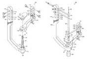
- FIG. 1is an elevational view of an exemplary embodiment of a targeting assembly having a rotating arm in a first rotational position, in accordance with the present disclosure
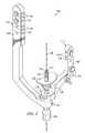
- FIG. 2is an elevational view of the targeting assembly shown in FIG. 1 having the rotating arm in a second rotational position, in accordance with the present disclosure
- FIG. 3is a cross-sectional view of the targeting assembly shown in FIG. 1 ;
- FIG. 4is an exploded view of the targeting assembly shown in FIG. 1 ;
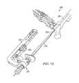
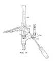
- FIG. 5is an elevational view of an exemplary embodiment of a compression system in accordance with the present disclosure.
- FIG. 6is a cross-sectional view of a compression nail seated on a connector shaft of the compression system in FIG. 5 ;
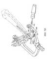
- FIG. 7Ais a schematic illustration of using the compression system in FIG. 5 to insert a nail into an ankle
- FIG. 7Bis a schematic illustration of using the compression system in FIG. 5 to insert a screw into a talus bone
- FIG. 7Cis a schematic illustration of using the compression system in FIG. 5 to insert a screw into a tibia bone
- FIG. 7Dis a schematic illustration of using the compression system in FIG. 5 to insert a screw into a calcaneus bone in a lateral to medial direction;
- FIG. 7Eis a schematic illustration of using the compression system in FIG. 5 to insert a screw into a calcaneus bone in a posterior to anterior direction;
- FIG. 7Fis a schematic illustration of using the compression system in FIG. 5 to insert a tibio-talar compression screw in an oblique direction.
- FIG. 1shows an exemplary embodiment of a targeting assembly 100 that may be used for the implantation of a compression nail in an ankle or other suitable human tissues.
- the targeting assembly 100may include a connecting shaft 102 for connecting a first arm 104 and a second arm 106 .
- the first and second arms 104 and 106may be made of a radio-translucent material.
- the first arm 104may include a proximal portion 110 and a base portion 112 , in which the base portion 112 of the first arm 104 is connected to the connecting shaft 102 .
- the first arm 104 and the connecting shaft 102may be rotationally fixed relative to each other to provide improved stability.
- the first arm 104may be rotatably coupled to the connecting shaft 102 and thus operable to rotate about the connecting shaft 102 .
- the second arm 106may include a proximal portion 114 and a base portion 116 , in which the base portion 114 of the second arm 106 is rotatably coupled to the connecting shaft 102 .
- the proximal portion 114 of the second arm 106may be operable to rotate about a longitudinal axis 108 defined by the connecting shaft 102 .
- the second arm 106may rotate from a first rotational position as shown in FIG. 1 to a second rotational position separated by a predetermined angular displacement.
- FIG. 2shows an exemplary embodiment of the targeting assembly 100 , with the second arm 106 rotated to an exemplary second rotational position.
- the first and second rotational positionshave an angular displacement of 90 degrees.
- the second arm 106may be rotated to any rotation position as needed to allow the desired approach to insert a screw.
- the second arm 106is operable to rotate about the longitudinal axis 108 in increments of predetermined angular displacements, such as 30, 45, 60, 90, or 180 degrees.
- predetermined angular displacementssuch as 30, 45, 60, 90, or 180 degrees.
- the first arm 104may include at least one alignment hole 118 defined through the proximal portion 110 of the first arm 104
- the second arm 106may include at least one alignment hole 120 defined through the proximal portion 114 of the second arm 106 .
- the alignment holes 118 and 120allow a surgeon to target, drill, and insert screws through the bone and into a compression nail (not shown) in the desired orientation, which will be discussed in greater details below.
- each of the first arm 104 and second arm 106includes a plurality of alignment holes 118 and 120 , respectively.
- first and second arms 104 and 106may be configured to have the same or different number of alignment holes 118 and 120 , respectively, which can be one, two, three, four, five, or greater, depending the surgical needs and the number of options desired or the relative geometry of any associated implant.
- FIG. 3is a cross-sectional view of the targeting assembly 100 illustrating a distance D 1 between one alignment hole 118 of the first arm 104 and the base portion 112 of the first arm 104 . Also illustrated in FIG. 3 is a distance D 2 between one alignment hole 120 of the second arm 106 and the base portion 116 of the second arm 106 .
- D 1may be configured to be greater than D 2 to reduce any misalignment of the alignment hole 120 due to the rotation of the second arm 106 . It is to be appreciated that the farther away the alignment hole 120 is disposed from a point of rotation, the larger magnification of any misalignment would be resulted.
- the rotating second arm 106may have a smaller D 2 than the D 1 of the fixed first arm 104 .
- the endpoints of D 1 and D 2may be defined in a number of ways.
- the endpoints of D 1are the center of an alignment hole 118 and a point along the longitudinal axis 108 within the base portion 112 .
- an endpoint along the longitudinal 108 axismay approximate a center of rotation of the first arm 104 or second arm 106 .
- endpoints of D 1 and D 2may be proximate to the alignment holes 118 and 120 and the longitudinal axis 108 .
- FIG. 4is an exploded view of the targeting assembly 100 showing exemplary mechanisms for connecting the first and second arms 104 and 106 to the connecting shaft 102 .
- various mechanismsmay be used to connect the first arm 104 to the connecting shaft 102 .
- the connecting shaft 102 and the first arm 104may be modular components that are releasably coupled using any suitable coupling mechanisms known in the art.
- the connecting shaft 102 and the first arm 104may be preassembled or integrally formed into one part.
- the connecting shaft 102 and the second arm 106may also releasably coupled using any suitable coupling mechanisms known in the art.
- one suitable mechanismis a latch mechanism.
- the connecting shaft 102may include a latch 124 and a plurality of recessed areas 122 defined in a circumferential surface of the connecting shaft 102 .
- the latch 124is operable to be received in one of the plurality of recessed areas 122 and engage the base portion 116 of the second arm 106 , thereby keeping the second arm 106 in one rotational position about the longitudinal axis 108 .
- the plurality of recessed areas 122may be spaced apart circumferentially by predetermined angular displacements, and the second arm 106 may rotate about the longitudinal axis 108 in increments substantially equal to the predetermined angular displacements.
- the latch 124may be released from the recessed area 122 to rotate the second arm 106 until a predetermined angular displacement is reached, at which point the latch 124 would be received in another recessed area 122 and seating the second arm 106 in a new rotational position.
- the latch 124may be mechanically coupled to or a part of a manual switch 126 such that a surgeon may use the switch 126 to remove the latch 124 from recessed areas 122 and allow a rotation of the second arm 106 .
- the latch 124may be a spring-load pin removable by pressing on a switch 126 .
- various increments of predetermined angular displacementsmay be used, such as 30, 45, 60, 90, or 180 degrees.
- the incrementsneed not be the same, and the amount of predetermined angular displacement for each increment may be customized to satisfy the operative preferences of the surgeon.
- some embodiments of the targeting assembly 100may further include a compression element 128 and a cup 130 adjacent to the compression element 128 .
- the compression element 128may be threadably coupled to the connecting shaft 102 , and the connecting shaft 102 may be disposed through a central opening of the cup 130 .
- the compression element 128may comprise an internally threaded surface operable to mate with an externally threaded portion 132 of the connecting shaft 102 . As such, a rotation of the compression element 128 would translate the cup 130 along the longitudinal axis 108 .
- the illustrated compression element 128may be desirable in some embodiments due to its ease of adjustment, but in other embodiments, other types of compression elements may be used to translate the cup 130 .
- the targeting assembly 100may further include a rod 140 , and the connecting shaft 102 may have a central bore that receives the rod 140 therein.
- the rod 140may include a tip 142 that extends upwardly outside of a top opening of the connecting shaft 102 and adjacent to a plurality of tabs 144 disposed on an end portion of the connecting shaft 102 .
- the tip 142may be threaded to engage complementary threads of an end portion of a nail (not shown) and rotate the nail to lock against the tabs 144 .
- the second arm 106may further include an angular adjustment mechanism 134 operable to secure an oblique aiming guide (not shown) along an oblique axis (not shown) that is offset from the longitudinal axis 108 .
- an angular adjustment mechanism 134operable to secure an oblique aiming guide (not shown) along an oblique axis (not shown) that is offset from the longitudinal axis 108 .
- a screw(not shown) may be inserted at an oblique orientation while not being targeted at a nail (not shown), which will be further discussed below.
- the use of the targeting assemblymay allow for a number of advantages, which will be discussed with reference to an exemplary embodiment of a compression nail system 200 shown in FIG. 5 .
- the compression nail system 200includes a targeting assembly 201 , which is substantially similar to the targeting assembly 100 shown in FIGS. 1-4 .
- the targeting assembly 201includes a connecting shaft 202 for connecting a first arm 204 and a second arm 206 , and each of first arm 204 and second arm 206 may include a plurality of alignment holes 218 and 220 , respectively.
- the first arm 204may include a proximal portion 210 and a base portion 212 , which is connected to the connecting shaft 202 .
- the first arm 204 and the connecting shaft 202may be rotationally fixed relative to each other.
- the first arm 204may be rotatably coupled to the connecting shaft 102 and thus operable to rotate about the connecting shaft 202 .
- the second arm 206may include a proximal portion 214 and a base portion 216 , which is rotatably coupled to the connecting shaft 202 .
- the proximal portion 214 of the second arm 206may be operable to rotate about a longitudinal axis 208 defined by the connecting shaft 202 .
- the second arm 206is operable to rotate about the longitudinal axis 208 in increments of predetermined angular displacements, such as 30, 45, 60, 90, or 180 degrees.
- the second arm 206may be releasably coupled to the connector shaft 202 according the principles disclosed in the present disclosure to allow for incremental rotation of the second arm 206 .
- the targeting assembly 201may further include a compression element 228 and a cup 230 adjacent to the compression element 228 .
- the compression element 228may be threadably coupled to the connecting shaft 202 , and the connecting shaft 202 may be disposed through a central opening of the cup 230 . As such, a rotation of the compression element is 228 would translate the cup 230 along the longitudinal axis 208 .
- the compression element 228may comprise an internally threaded surface operable to mate with an externally threaded portion 232 of the connecting shaft 202 .
- the compression nail system 200may also include a nail 240 seated proximate an end portion of the connecting shaft 202 .
- the targeting assembly 201may include a rod 290
- the connecting shaft 202may have a central bore that receives the rod 290 therein.
- the rod 290may include a tip 292 that extends upwardly outside of a top opening of the connecting shaft 202 and adjacent to a plurality of tabs 294 disposed on an end portion of the connecting shaft 202 .
- the tip 292may be threaded to engage complementary threads of an end portion of the nail 240 .
- a rotation of the rod 290would rotate the nail 240 to lock it against the tabs 294 .
- the nail 240may be aligned substantially along the longitudinal axis 208 .
- a longitudinal aperture 262 of the rod 290may meet an internal aperture 264 of the nail 240 .
- the internal aperture 264 of the nail 240is accessible from the exterior of the targeting assembly 201 through the longitudinal aperture 262 of the rod 290 .
- the nail 240may include a plurality of screw holes 242 , 244 , 246 , 248 , and 250 defined therethrough.
- first and second screw holes 242 and 244may each define a lateral axis (not shown) orthogonal to the longitudinal axis.
- the first and second screw holes 242 and 244may define lateral axes (not shown) that are orthogonal to each other.
- the first screw hole 242may be oriented such that it would be in lateral alignment with a first alignment hole 220 a when the second arm 206 is in a first rotational position.
- the second screw hole 244may be oriented such that it would be in lateral alignment with a second alignment hole 220 b when the second arm 206 is in a second rotational position.
- the first rotational positionmay be the rotational position of the second arm 206 as shown in FIG. 5 , in which the second arm 206 is angularly displaced from the rotational position of the first arm 204 by approximately 90 degrees.
- the second arm 206may be rotated to a second rotational position where it would be angularly displaced from the rotational position of the first arm 204 by approximately 180 degrees.
- first and second rotational positions of the second arm 206may be a variety of angular displacements from the first arm 204 .
- the first and second rotational positions of the second arm 206may be adjusted accordingly.
- the nail 240may be any compression nail known in the art, including nails for ankle arthrodesis or other orthopedic procedures requiring compression of one or more bones. It is to be appreciated that a nail 240 of a variety of lengths and diameters may be attached to the connecting shaft 202 . Targeted through the alignment holes of the first and second arms 204 and 206 of the targeting assembly 201 , bone screws (not shown) may be inserted through the various screw holes of the nail 240 , thereby locking the nail 240 to the anatomy of a patient.
- tibia, talus, and calcaneusIn an ankle arthrodesis procedure, there are typically several screws that are inserted into the related bones (in this case the tibia, talus, and calcaneus) and these screws are sometimes placed in a medial-lateral (M/L) or anterior-posterior (A/P) direction.
- M/L and A/P screw placementsmay have as much to do with anatomy as it does with surgeon preference, and the targeting assembly 201 of the nail system 200 may allow the surgeon to pick the best and most suited option based on the patient and surgical preferences.
- tibial screws, the talar screw, and the upper calcaneal screwmay be implanted in an M/L configuration thru the nail 240 .
- surgeonsmay be approaching in a lateral-medial (L/M) configuration.
- Conventional targeting assembliesmay include targeting arms that rotate about the nail to accommodate either an M/L or A/P placement of screws. But a problem associated with conventional targeting assemblies is that when the arm is rotated, there is a risk that the alignment of the targeting arm holes to the holes in the nail is compromised. This is a particular concern for the most proximal holes on the targeting arm and the nail as they are typically the furthest away a point of rotation and are therefore usually the most affected by a magnified misalignment. In this respect, advantages of the targeting assembly 201 may include stability provided by the first arm 204 and the connecting shaft 202 being rotationally fixed relative to each other.
- alignment holes 218which may be the most proximal alignment holes of the targeting assembly 201 , are rotationally fix relative to the nail 240 , thereby reducing or eliminating the risk of misalignment due the rotation of the first arm 204 and resulting in high targeting accuracy.
- the second arm 206may be allowed to rotate around the nail 240 to accommodate various screw options as discussed in the present disclosure, including the distal screws around the joint (e.g., talar, M/L calcaneal, and A/P calcaneal). Because the holes 220 of the second arm 206 are closer to the point of rotation of the second arm 206 , they are less susceptible to the targeting inaccuracies due to rotation than the holes 218 of the first arm 204 would be.
- the targeting assembly 201may include an angular adjustment mechanism 234 operable to secure an oblique aiming guide (not shown) along an oblique axis (not shown) that is offset from the longitudinal axis 208 .
- screwsmay be inserted posterior-anterior (P/A) from the back of the calcaneus upwards toward the talus.
- P/Aposterior-anterior
- One reason to do sois to offer additional fixation and compression across this joint, but a difficulty in inserting fixation screws in this manner may be the targeting. After the nail and associated screws have been inserted, there is only a small amount of “free space” left to utilize such screws.
- the angular adjustment mechanism 234is operable to target a screw along an oblique axis offset from the longitudinal axis 208 , thereby avoiding targeting nail 240 and instead targeting either side of the nail 240 .
- FIG. 7AShown in FIG. 7A is a patient's ankle, which has been surgically prepared to include an aperture 302 defined through the calcaneus, talus, and tibia for receiving the nail 240 .
- the nail 240is attached to the targeting assembly 201 , with both the first and second arms 204 and 206 aligned in the same plane.
- the nail 240may be inserted into the aperture 302 by passing the nail 240 through a guide wire 304 disposed through a longitudinal aperture (shown in FIG. 6 ) of the connector shaft 202 .
- the first and second arms 204 and 206may be angularly displaced from each other as the nail 240 is inserted (not shown).
- the nail 240may be inserted without the help of the guide wire 304 .
- the first arm 204may be positioned for an M/L approach for the tibia screws (not shown), and the second arm 206 may be rotated to a first rotational position for an L/M approach for a talar screw 260 , as shown in FIG. 7B .
- the first arm 204may be positioned for an L/M approach, and the second arm 206 may be rotated to a rotational position for an M/L approach.
- a screw guide 262may cooperate with the second arm 206 to target and insert the talar screw 260 through a corresponding screw hole in the nail 240 and into the talus.
- two screw guides 266may cooperate with the first arm 204 to target and insert tibial screws 280 through corresponding screw holes in the nail 240 and into the tibia.
- the tibial screws 280may be implanted in an M/L approach as shown in FIG. 7C or in an L/m approach.
- internal compression of the tibio-talar jointmay be effected by activating a suitable internal mechanism (not shown) of the nail 240 .
- a variety of internal mechanismsmay be used for effecting internal compression in the compression nail system 200 . These internal mechanisms are well-known in the art and thus would be described here.
- external compression of the subtalar jointmay be effected by adjusting the compression element 228 to advance the cup 230 in a proximal direction until the desired compression is achieved.
- the second arm 206may be rotated to the desired rotational positions to allow the insertion of two calcaneal screws 268 after the internal and external compressions have been achieved.
- the second arm 206is rotated to the first rotational position as shown in FIG. 7D for the insertion of a first calcaneal screw 268 in a L/M approach, and then the second arm 206 is rotated to a second rotation position as shown in FIG. 7E for the insertion of a second calcaneal screw 268 in a P/A approach.
- the targeting and insertion of the calcaneal screws 268may be accomplished with the guiding of a screw guide 270 . It is to be appreciated in other embodiments, the order of the insertion of the first and second calcaneal screws 268 may be varied and the approach of the insertion may be varied.
- an oblique screw 272may be implanted to obtain increased rigidity of the construct and to maintain compression before release of the external compression.
- an oblique aiming guide 274 coupled to the angular adjustment mechanism 234may be used to target and insert the oblique screw 272 along an oblique axis (not shown) offset from the longitudinal axis 208 (not shown), thereby avoiding targeting nail 240 and instead targeting either side of the nail 240 .
- the angular adjustment mechanism 234may include a guide knob operable to adjust the angular orientation of the oblique aiming guide 274 .
Landscapes
- Health & Medical Sciences (AREA)
- Surgery (AREA)
- Life Sciences & Earth Sciences (AREA)
- Orthopedic Medicine & Surgery (AREA)
- Biomedical Technology (AREA)
- Public Health (AREA)
- Veterinary Medicine (AREA)
- Engineering & Computer Science (AREA)
- Nuclear Medicine, Radiotherapy & Molecular Imaging (AREA)
- Heart & Thoracic Surgery (AREA)
- Medical Informatics (AREA)
- Molecular Biology (AREA)
- Animal Behavior & Ethology (AREA)
- General Health & Medical Sciences (AREA)
- Dentistry (AREA)
- Oral & Maxillofacial Surgery (AREA)
- Neurology (AREA)
- Surgical Instruments (AREA)
- Prostheses (AREA)
Abstract
Description
Claims (15)
Priority Applications (1)
| Application Number | Priority Date | Filing Date | Title |
|---|---|---|---|
| US13/586,619US9241744B2 (en) | 2011-08-15 | 2012-08-15 | Targeting assembly for a compression nail system |
Applications Claiming Priority (2)
| Application Number | Priority Date | Filing Date | Title |
|---|---|---|---|
| US201161523814P | 2011-08-15 | 2011-08-15 | |
| US13/586,619US9241744B2 (en) | 2011-08-15 | 2012-08-15 | Targeting assembly for a compression nail system |
Publications (2)
| Publication Number | Publication Date |
|---|---|
| US20130046311A1 US20130046311A1 (en) | 2013-02-21 |
| US9241744B2true US9241744B2 (en) | 2016-01-26 |
Family
ID=47713166
Family Applications (1)
| Application Number | Title | Priority Date | Filing Date |
|---|---|---|---|
| US13/586,619Active2033-11-10US9241744B2 (en) | 2011-08-15 | 2012-08-15 | Targeting assembly for a compression nail system |
Country Status (8)
| Country | Link |
|---|---|
| US (1) | US9241744B2 (en) |
| EP (1) | EP2744430B1 (en) |
| JP (1) | JP6035333B2 (en) |
| AU (1) | AU2012296567B2 (en) |
| BR (1) | BR112014003571B1 (en) |
| CA (1) | CA2845255C (en) |
| ES (1) | ES2644292T3 (en) |
| WO (1) | WO2013025825A2 (en) |
Cited By (20)
| Publication number | Priority date | Publication date | Assignee | Title |
|---|---|---|---|---|
| WO2018157170A1 (en)* | 2017-02-27 | 2018-08-30 | Paragon 28, Inc. | Targeting instruments, systems and methods of use |
| US20190069911A1 (en)* | 2016-02-19 | 2019-03-07 | Sunnybrook Research Institute | Positioning and alignment instrument for introducing surgical devices into bone |
| US10327829B2 (en) | 2012-12-28 | 2019-06-25 | Paragon 28, Inc. | Alignment guide apparatus, methods and systems |
| US10492803B2 (en) | 2016-09-22 | 2019-12-03 | Globus Medical, Inc. | Systems and methods for intramedullary nail implantation |
| US10610241B2 (en) | 2016-10-24 | 2020-04-07 | Paragon 28, Inc. | Osteotomy systems, devices and methods |
| US10786292B2 (en) | 2017-06-16 | 2020-09-29 | Stryker European Holdings I, Llc | Patient-specific bridging plates |
| US10799276B2 (en) | 2017-07-11 | 2020-10-13 | Paragon 28, Inc. | Bone fixation system, assembly, implants, devices, insertion guides, and methods of use |
| US10849665B2 (en) | 2018-10-29 | 2020-12-01 | Stryker European Operations Holdings Llc | Snap-fit cutting guides and plating systems |
| US10888338B2 (en)* | 2017-02-27 | 2021-01-12 | Paragon 28, Inc. | Intramedullary nail alignment guides, fixation guides, devices, systems, and methods of use |
| US10918431B2 (en) | 2017-03-30 | 2021-02-16 | Paragon 28, Inc. | Bone fixation system, assembly, implants, devices, alignment guides, and methods of use |
| US11033333B2 (en) | 2017-04-06 | 2021-06-15 | Stryker European Holdings I, Llc | Plate selection user interface and design tool with database |
| US11083503B2 (en) | 2016-09-22 | 2021-08-10 | Globus Medical, Inc. | Systems and methods for intramedullary nail implantation |
| US11123120B2 (en) | 2018-07-11 | 2021-09-21 | Paragon 28, Inc. | Implants, alignment guides, systems and methods of use |
| US20220183857A1 (en)* | 2019-02-21 | 2022-06-16 | MEDACTA lNTERNATIONAL SA | Positioning device of a surgical instrument for hip arthroplasty surgery |
| US20220378484A1 (en)* | 2021-05-28 | 2022-12-01 | Acumed Llc | Bone fixation systems and nail having compressive threading |
| US11540846B2 (en) | 2019-10-22 | 2023-01-03 | DePuy Synthes Products, Inc. | Aiming device for intramedullary nails, and related systems and methods |
| US11633219B2 (en) | 2019-06-26 | 2023-04-25 | Globus Medical, Inc. | Fenestrated pedicle nail |
| US11925364B2 (en) | 2019-02-13 | 2024-03-12 | Paragon 28, Inc. | Implant, alignment guides, system and methods of use |
| US12076031B2 (en) | 2019-02-14 | 2024-09-03 | Paragon 28, Inc. | Threaded targeting instruments, systems and methods of use |
| US12171442B2 (en) | 2019-02-28 | 2024-12-24 | Paragon 28, Inc. | Fusion systems, instruments, bone plates and methods of use |
Families Citing this family (13)
| Publication number | Priority date | Publication date | Assignee | Title |
|---|---|---|---|---|
| WO2013123366A1 (en) | 2012-02-16 | 2013-08-22 | Paragon 28, Inc. | Charco-resis implant, alignment instrument, system and method of use |
| BR112015018616A2 (en)* | 2013-03-14 | 2017-07-18 | Wright Medical Tech Inc | intramedullary technique and system for the ankle |
| ES2959525T3 (en)* | 2013-03-15 | 2024-02-26 | Paragon 28 Inc | intramedullary nail |
| US20150157338A1 (en)* | 2013-12-05 | 2015-06-11 | Jonathan Feibel | Targeting device for use with systems, methods, and apparatuses for fusion, stabilization, and/or fixation of bones |
| JP6687595B2 (en)* | 2014-07-15 | 2020-04-22 | オーティ メディツィンテヒニック ゲーエムベーハー | Positioning device for fixing intramedullary nail to long bone |
| CA2887377C (en) | 2014-09-11 | 2017-05-30 | Wright Medical Technology, Inc. | Guidance system and method for bone fusion |
| US11076896B2 (en)* | 2016-01-20 | 2021-08-03 | Ot Medizintechnik Gmbh | Positioning-device module for releasable connection to a positioning device, positioning device and set |
| IT201700048446A1 (en) | 2017-05-04 | 2018-11-04 | Orthofix Srl | Improved bone screw for the treatment of sagging or bone deformation, such as in the case of the Charcot foot, and insertion instruments in the bone screw of anti-migration elements |
| FR3077476B1 (en)* | 2018-02-07 | 2022-10-21 | In2Bones | IMPROVED ARTHRODESIS DEVICE |
| WO2020117148A2 (en)* | 2018-04-04 | 2020-06-11 | Tst Rakor Ve Tibbi̇ Aletler Sanayi̇ Ve Ti̇caret Li̇mi̇ted Şi̇rketi̇ | Proximal femoral de-rotation nail |
| EP3930609A4 (en) | 2019-02-28 | 2022-12-28 | Paragon 28, Inc. | Implants, systems, and methods of use |
| US10987146B2 (en)* | 2019-03-05 | 2021-04-27 | Nextremity Solutions, Inc. | Bone defect repair apparatus and method |
| WO2021050331A1 (en) | 2019-09-12 | 2021-03-18 | Paragon 28, Inc. | Implant guides, devices, systems, and methods of use |
Citations (9)
| Publication number | Priority date | Publication date | Assignee | Title |
|---|---|---|---|---|
| US6033407A (en)* | 1998-01-27 | 2000-03-07 | Behrens; Alfred F. | Apparatus and method for intramedullary nailing and intramedullary nail therefor |
| US20050245934A1 (en) | 2004-03-09 | 2005-11-03 | Finsbury (Development) Limited | Tool |
| US20080221577A1 (en)* | 2007-01-26 | 2008-09-11 | Ebi, Llc | Intramedullary implant with locking and compression devices |
| US20090093813A1 (en) | 2007-10-04 | 2009-04-09 | Ebi, L.P. | Alignment device for locking nail |
| US20090099571A1 (en) | 2007-10-10 | 2009-04-16 | Ebi, Llc | Variable angle targeting device |
| US20090234369A1 (en) | 2006-06-19 | 2009-09-17 | Robarts Research Institute | Apparatus for guiding a medical tool |
| US20090299375A1 (en) | 2008-06-03 | 2009-12-03 | Zimmer, Inc. | Catheter nail targeting guide |
| US20120109217A1 (en)* | 2010-05-06 | 2012-05-03 | Christophe Perineau | Anterior-to-posterior talus-calcaneus screw insertion for ankle arthrodesis nail |
| US20120226326A1 (en)* | 2010-09-09 | 2012-09-06 | Tom Overes | Surgical Nail |
Family Cites Families (8)
| Publication number | Priority date | Publication date | Assignee | Title |
|---|---|---|---|---|
| EP0187283B1 (en) | 1984-12-26 | 1989-04-26 | Nivarox-FAR S.A. | Device to locate in situ through-holes in a hollow pin that is implanted into the medullary canal for the retention of the fragments of a fractured bone |
| JP3046822B1 (en)* | 1999-09-01 | 2000-05-29 | 株式会社ホムズ技研 | Intramedullary nail positioning device |
| EP1759643A1 (en)* | 2005-08-30 | 2007-03-07 | Orthofix International B.V. | Targeting device for intramedullary nails |
| EP1996096A4 (en)* | 2006-03-22 | 2012-09-05 | Depuy Products Inc | Nail plate and jig therefor |
| US8685034B2 (en)* | 2006-08-10 | 2014-04-01 | Stryker Trauma Gmbh | Distal targeting device |
| ITUD20070099A1 (en)* | 2007-05-31 | 2008-12-01 | Enzo Scaglia | SURGICAL DEVICE |
| WO2009109371A2 (en)* | 2008-03-04 | 2009-09-11 | Sector 6 Technologies S.A. | Device for targeting locking holes in intramedullary nails |
| US8414584B2 (en)* | 2008-07-09 | 2013-04-09 | Icon Orthopaedic Concepts, Llc | Ankle arthrodesis nail and outrigger assembly |
- 2012
- 2012-08-15JPJP2014526180Apatent/JP6035333B2/enactiveActive
- 2012-08-15EPEP12823437.4Apatent/EP2744430B1/enactiveActive
- 2012-08-15USUS13/586,619patent/US9241744B2/enactiveActive
- 2012-08-15AUAU2012296567Apatent/AU2012296567B2/enactiveActive
- 2012-08-15ESES12823437.4Tpatent/ES2644292T3/enactiveActive
- 2012-08-15BRBR112014003571-7Apatent/BR112014003571B1/enactiveIP Right Grant
- 2012-08-15CACA2845255Apatent/CA2845255C/enactiveActive
- 2012-08-15WOPCT/US2012/050982patent/WO2013025825A2/enactiveApplication Filing
Patent Citations (9)
| Publication number | Priority date | Publication date | Assignee | Title |
|---|---|---|---|---|
| US6033407A (en)* | 1998-01-27 | 2000-03-07 | Behrens; Alfred F. | Apparatus and method for intramedullary nailing and intramedullary nail therefor |
| US20050245934A1 (en) | 2004-03-09 | 2005-11-03 | Finsbury (Development) Limited | Tool |
| US20090234369A1 (en) | 2006-06-19 | 2009-09-17 | Robarts Research Institute | Apparatus for guiding a medical tool |
| US20080221577A1 (en)* | 2007-01-26 | 2008-09-11 | Ebi, Llc | Intramedullary implant with locking and compression devices |
| US20090093813A1 (en) | 2007-10-04 | 2009-04-09 | Ebi, L.P. | Alignment device for locking nail |
| US20090099571A1 (en) | 2007-10-10 | 2009-04-16 | Ebi, Llc | Variable angle targeting device |
| US20090299375A1 (en) | 2008-06-03 | 2009-12-03 | Zimmer, Inc. | Catheter nail targeting guide |
| US20120109217A1 (en)* | 2010-05-06 | 2012-05-03 | Christophe Perineau | Anterior-to-posterior talus-calcaneus screw insertion for ankle arthrodesis nail |
| US20120226326A1 (en)* | 2010-09-09 | 2012-09-06 | Tom Overes | Surgical Nail |
Non-Patent Citations (1)
| Title |
|---|
| International Search Report and Written Opinion, PCT/US2012/050982, dated May 15, 2013, 9 pages. |
Cited By (41)
| Publication number | Priority date | Publication date | Assignee | Title |
|---|---|---|---|---|
| US10327829B2 (en) | 2012-12-28 | 2019-06-25 | Paragon 28, Inc. | Alignment guide apparatus, methods and systems |
| USD1045639S1 (en) | 2012-12-28 | 2024-10-08 | Paragon 28, Inc. | Alignment guide |
| US11395691B2 (en) | 2012-12-28 | 2022-07-26 | Paragon 28, Inc. | Alignment guide apparatus, methods and systems |
| US11779382B2 (en) | 2012-12-28 | 2023-10-10 | Paragon 28, Inc. | Alignment guide apparatus, methods and systems |
| US12295633B2 (en) | 2012-12-28 | 2025-05-13 | Paragon 28, Inc. | Alignment guide apparatus, methods and systems |
| US10869679B2 (en)* | 2016-02-19 | 2020-12-22 | Sunnybrook Research Institute | Positioning and alignment instrument for introducing surgical devices into bone |
| US20190069911A1 (en)* | 2016-02-19 | 2019-03-07 | Sunnybrook Research Institute | Positioning and alignment instrument for introducing surgical devices into bone |
| US10492803B2 (en) | 2016-09-22 | 2019-12-03 | Globus Medical, Inc. | Systems and methods for intramedullary nail implantation |
| US12285178B2 (en) | 2016-09-22 | 2025-04-29 | Globus Medical, Inc. | Systems and methods for intramedullary nail implantation |
| US11490905B2 (en) | 2016-09-22 | 2022-11-08 | Globus Medical, Inc. | Systems and methods for intramedullary nail implantation |
| US11083503B2 (en) | 2016-09-22 | 2021-08-10 | Globus Medical, Inc. | Systems and methods for intramedullary nail implantation |
| US11642142B2 (en) | 2016-10-24 | 2023-05-09 | Paragon 28, Inc. | Osteotomy systems, devices and methods |
| US10610241B2 (en) | 2016-10-24 | 2020-04-07 | Paragon 28, Inc. | Osteotomy systems, devices and methods |
| US12185953B2 (en) | 2016-10-24 | 2025-01-07 | Paragon 28, Inc. | Osteotomy systems, devices and methods |
| WO2018157170A1 (en)* | 2017-02-27 | 2018-08-30 | Paragon 28, Inc. | Targeting instruments, systems and methods of use |
| US11179168B2 (en) | 2017-02-27 | 2021-11-23 | Paragon 28, Inc. | Targeting instruments, systems and methods of use |
| US12178454B2 (en) | 2017-02-27 | 2024-12-31 | Paragon 28, Inc. | Targeting instruments, systems and methods of use |
| US20210128177A1 (en)* | 2017-02-27 | 2021-05-06 | Paragon 28, Inc. | Intramedullary nail alignment guides, fixation guides, devices, systems, and methods of use |
| US11779358B2 (en) | 2017-02-27 | 2023-10-10 | Paragon 28, Inc. | Targeting instruments, systems and methods of use |
| US10888338B2 (en)* | 2017-02-27 | 2021-01-12 | Paragon 28, Inc. | Intramedullary nail alignment guides, fixation guides, devices, systems, and methods of use |
| US12396768B2 (en) | 2017-02-27 | 2025-08-26 | Paragon 28, Inc. | Intramedullary nail alignment guides, fixation guides, devices, systems, and methods of use |
| US11666345B2 (en)* | 2017-02-27 | 2023-06-06 | Paragon 28, Inc. | Intramedullary nail alignment guides, fixation guides, devices, systems, and methods of use |
| US10918431B2 (en) | 2017-03-30 | 2021-02-16 | Paragon 28, Inc. | Bone fixation system, assembly, implants, devices, alignment guides, and methods of use |
| US12295634B2 (en) | 2017-03-30 | 2025-05-13 | Paragon 28, Inc. | Bone fixation system, assembly, implants, devices, alignment guides, and methods of use |
| US12161420B2 (en) | 2017-04-06 | 2024-12-10 | Stryker European Operations Holdings Llc | Plate selection user interface and design tool with database |
| US11033333B2 (en) | 2017-04-06 | 2021-06-15 | Stryker European Holdings I, Llc | Plate selection user interface and design tool with database |
| US11484354B2 (en) | 2017-06-16 | 2022-11-01 | Stryker European Operations Holdings Llc | Patient-specific bridging plates |
| US10786292B2 (en) | 2017-06-16 | 2020-09-29 | Stryker European Holdings I, Llc | Patient-specific bridging plates |
| US10799276B2 (en) | 2017-07-11 | 2020-10-13 | Paragon 28, Inc. | Bone fixation system, assembly, implants, devices, insertion guides, and methods of use |
| US11559316B2 (en) | 2017-07-11 | 2023-01-24 | Paragon 28, Inc. | Bone fixation system, assembly, implants, devices, insertion guides, and methods of use |
| US11123120B2 (en) | 2018-07-11 | 2021-09-21 | Paragon 28, Inc. | Implants, alignment guides, systems and methods of use |
| US10849665B2 (en) | 2018-10-29 | 2020-12-01 | Stryker European Operations Holdings Llc | Snap-fit cutting guides and plating systems |
| US11925364B2 (en) | 2019-02-13 | 2024-03-12 | Paragon 28, Inc. | Implant, alignment guides, system and methods of use |
| US12076031B2 (en) | 2019-02-14 | 2024-09-03 | Paragon 28, Inc. | Threaded targeting instruments, systems and methods of use |
| US12208022B2 (en)* | 2019-02-21 | 2025-01-28 | Medacta International Sa | Positioning device of a surgical instrument for hip arthroplasty surgery |
| US20220183857A1 (en)* | 2019-02-21 | 2022-06-16 | MEDACTA lNTERNATIONAL SA | Positioning device of a surgical instrument for hip arthroplasty surgery |
| US12171442B2 (en) | 2019-02-28 | 2024-12-24 | Paragon 28, Inc. | Fusion systems, instruments, bone plates and methods of use |
| US11633219B2 (en) | 2019-06-26 | 2023-04-25 | Globus Medical, Inc. | Fenestrated pedicle nail |
| US11540846B2 (en) | 2019-10-22 | 2023-01-03 | DePuy Synthes Products, Inc. | Aiming device for intramedullary nails, and related systems and methods |
| US20220378484A1 (en)* | 2021-05-28 | 2022-12-01 | Acumed Llc | Bone fixation systems and nail having compressive threading |
| US12144528B2 (en)* | 2021-05-28 | 2024-11-19 | Acumed Llc | Bone fixation systems and nail having compressive threading |
Also Published As
| Publication number | Publication date |
|---|---|
| CA2845255C (en) | 2020-02-18 |
| CA2845255A1 (en) | 2013-02-21 |
| US20130046311A1 (en) | 2013-02-21 |
| EP2744430A2 (en) | 2014-06-25 |
| WO2013025825A3 (en) | 2013-07-25 |
| EP2744430A4 (en) | 2015-03-18 |
| ES2644292T3 (en) | 2017-11-28 |
| JP6035333B2 (en) | 2016-11-30 |
| JP2014529428A (en) | 2014-11-13 |
| BR112014003571A2 (en) | 2017-04-04 |
| BR112014003571B1 (en) | 2021-03-09 |
| AU2012296567B2 (en) | 2017-02-23 |
| WO2013025825A2 (en) | 2013-02-21 |
| AU2012296567A1 (en) | 2014-03-06 |
| EP2744430B1 (en) | 2017-06-14 |
Similar Documents
| Publication | Publication Date | Title |
|---|---|---|
| US9241744B2 (en) | Targeting assembly for a compression nail system | |
| US12295634B2 (en) | Bone fixation system, assembly, implants, devices, alignment guides, and methods of use | |
| US11559316B2 (en) | Bone fixation system, assembly, implants, devices, insertion guides, and methods of use | |
| US11395691B2 (en) | Alignment guide apparatus, methods and systems | |
| US20250241694A1 (en) | Bone fixation assembly, implants and methods of use | |
| EP3023068B1 (en) | Bone plates, plate alignment systems, and methods of use | |
| EP3820382B1 (en) | Systems comprising alignment guides and implants | |
| US11925364B2 (en) | Implant, alignment guides, system and methods of use |
Legal Events
| Date | Code | Title | Description |
|---|---|---|---|
| AS | Assignment | Owner name:AMEI TECHNOLOGIES, INC., DELAWARE Free format text:ASSIGNMENT OF ASSIGNORS INTEREST;ASSIGNORS:BLAKE, STEPHEN;FRANCO, MIGUEL;PROTOPSALTIS, DIMITRI;AND OTHERS;SIGNING DATES FROM 20140305 TO 20140416;REEL/FRAME:032902/0033 | |
| AS | Assignment | Owner name:JPMORGAN CHASE BANK, N.A., AS ADMINISTRATIVE AGENT Free format text:SECURITY INTEREST;ASSIGNOR:AMEI TECHNOLOGIES INC.;REEL/FRAME:036649/0821 Effective date:20150831 | |
| STCF | Information on status: patent grant | Free format text:PATENTED CASE | |
| AS | Assignment | Owner name:ORTHOFIX S.R.L., ITALY Free format text:ASSIGNMENT OF ASSIGNORS INTEREST;ASSIGNOR:AMEI TECHNOLOGIES INC.;REEL/FRAME:047502/0769 Effective date:20171219 | |
| MAFP | Maintenance fee payment | Free format text:PAYMENT OF MAINTENANCE FEE, 4TH YEAR, LARGE ENTITY (ORIGINAL EVENT CODE: M1551); ENTITY STATUS OF PATENT OWNER: LARGE ENTITY Year of fee payment:4 | |
| MAFP | Maintenance fee payment | Free format text:PAYMENT OF MAINTENANCE FEE, 8TH YEAR, LARGE ENTITY (ORIGINAL EVENT CODE: M1552); ENTITY STATUS OF PATENT OWNER: LARGE ENTITY Year of fee payment:8 | |
| AS | Assignment | Owner name:JPMORGAN CHASE BANK, N.A., AS ADMINISTRATIVE AGENT, ILLINOIS Free format text:SECURITY INTEREST;ASSIGNOR:ORTHOFIX S.R.L.;REEL/FRAME:065381/0804 Effective date:20231012 | |
| AS | Assignment | Owner name:ORTHOFIX S.R.L., ITALY Free format text:RELEASE BY SECURED PARTY;ASSIGNOR:JPMORGAN CHASE BANK, N.A.;REEL/FRAME:065609/0233 Effective date:20231106 |