US9241687B2 - Ablation probe with ultrasonic imaging capabilities - Google Patents
Ablation probe with ultrasonic imaging capabilitiesDownload PDFInfo
- Publication number
- US9241687B2 US9241687B2US13/437,267US201213437267AUS9241687B2US 9241687 B2US9241687 B2US 9241687B2US 201213437267 AUS201213437267 AUS 201213437267AUS 9241687 B2US9241687 B2US 9241687B2
- Authority
- US
- United States
- Prior art keywords
- probe
- electrode
- ultrasonic imaging
- ultrasonic
- ablation
- Prior art date
- Legal status (The legal status is an assumption and is not a legal conclusion. Google has not performed a legal analysis and makes no representation as to the accuracy of the status listed.)
- Active, expires
Links
Images


Classifications
- A—HUMAN NECESSITIES
- A61—MEDICAL OR VETERINARY SCIENCE; HYGIENE
- A61B—DIAGNOSIS; SURGERY; IDENTIFICATION
- A61B8/00—Diagnosis using ultrasonic, sonic or infrasonic waves
- A61B8/44—Constructional features of the ultrasonic, sonic or infrasonic diagnostic device
- A61B8/4477—Constructional features of the ultrasonic, sonic or infrasonic diagnostic device using several separate ultrasound transducers or probes
- A—HUMAN NECESSITIES
- A61—MEDICAL OR VETERINARY SCIENCE; HYGIENE
- A61B—DIAGNOSIS; SURGERY; IDENTIFICATION
- A61B8/00—Diagnosis using ultrasonic, sonic or infrasonic waves
- A61B8/08—Clinical applications
- A61B8/0883—Clinical applications for diagnosis of the heart
- A—HUMAN NECESSITIES
- A61—MEDICAL OR VETERINARY SCIENCE; HYGIENE
- A61B—DIAGNOSIS; SURGERY; IDENTIFICATION
- A61B8/00—Diagnosis using ultrasonic, sonic or infrasonic waves
- A61B8/12—Diagnosis using ultrasonic, sonic or infrasonic waves in body cavities or body tracts, e.g. by using catheters
- A—HUMAN NECESSITIES
- A61—MEDICAL OR VETERINARY SCIENCE; HYGIENE
- A61B—DIAGNOSIS; SURGERY; IDENTIFICATION
- A61B8/00—Diagnosis using ultrasonic, sonic or infrasonic waves
- A61B8/44—Constructional features of the ultrasonic, sonic or infrasonic diagnostic device
- A61B8/4444—Constructional features of the ultrasonic, sonic or infrasonic diagnostic device related to the probe
- A61B8/445—Details of catheter construction
- A—HUMAN NECESSITIES
- A61—MEDICAL OR VETERINARY SCIENCE; HYGIENE
- A61B—DIAGNOSIS; SURGERY; IDENTIFICATION
- A61B8/00—Diagnosis using ultrasonic, sonic or infrasonic waves
- A61B8/46—Ultrasonic, sonic or infrasonic diagnostic devices with special arrangements for interfacing with the operator or the patient
- A61B8/461—Displaying means of special interest
- A61B8/463—Displaying means of special interest characterised by displaying multiple images or images and diagnostic data on one display
- A—HUMAN NECESSITIES
- A61—MEDICAL OR VETERINARY SCIENCE; HYGIENE
- A61B—DIAGNOSIS; SURGERY; IDENTIFICATION
- A61B6/00—Apparatus or devices for radiation diagnosis; Apparatus or devices for radiation diagnosis combined with radiation therapy equipment
- A61B6/12—Arrangements for detecting or locating foreign bodies
- A—HUMAN NECESSITIES
- A61—MEDICAL OR VETERINARY SCIENCE; HYGIENE
- A61B—DIAGNOSIS; SURGERY; IDENTIFICATION
- A61B6/00—Apparatus or devices for radiation diagnosis; Apparatus or devices for radiation diagnosis combined with radiation therapy equipment
- A61B6/48—Diagnostic techniques
- A61B6/486—Diagnostic techniques involving generating temporal series of image data
- A61B6/487—Diagnostic techniques involving generating temporal series of image data involving fluoroscopy
Definitions
- the present disclosurerelates generally to devices and systems for imaging anatomical structures within the body. More specifically, the present disclosure relates to an ablation probe with ultrasonic imaging capabilities.
- EPinterventional cardiac electrophysiology
- the physicianmay deliver a mapping catheter through a main vein or artery into an interior region of the heart to be treated. Using the mapping catheter, the physician may then determine the source of a cardiac rhythm disturbance or abnormality by placing a number of mapping elements carried by the catheter into contact with the adjacent cardiac tissue and then operate the catheter to generate an electrophysiology map of the interior region of the heart.
- the physicianmay then advance an ablation catheter into the heart, and position an ablation electrode carried by the catheter tip near the targeted cardiac tissue to ablate the tissue and form a lesion, thereby treating the cardiac rhythm disturbance or abnormality.
- the ablation catheteritself may include a number of mapping electrodes, allowing the same device to be used for both mapping and ablation.
- ultrasound-based imaging catheters and probeshave been developed for directly visualizing body tissue in applications such as interventional cardiology, interventional radiology, and electrophysiology.
- ultrasound imaging deviceshave been developed that permit the visualization of anatomical structures of the heart directly and in real-time.
- ultrasound cathetersmay be used to image the intra-atrial septum, to guide transseptal crossing of the atrial septum, to locate and image the pulmonary veins, and to monitor the atrial chambers of the heart for signs of a perforation and pericardial effusion.
- ultrasound-based imaging systemscomprise an imaging probe that is separate from the mapping and ablation catheters used to perform therapy on the patient.
- a position tracking systemis sometimes used to track the location of each device within the body.
- the images obtained using many ultrasound-based imaging systemsare often difficult to read and understand without reference to images obtained from a separate imaging system such as a fluoroscopic imaging system.
- a combined ablation and ultrasound imaging probe for insertion within a bodycomprises: a housing having a proximal section and a distal tip section; an ablation electrode located at the distal tip section; a first ultrasonic imaging sensor located on the distal tip section, the first ultrasonic imaging sensor configured to transmit acoustic waves in a first direction distal to the distal tip section; and a plurality of second ultrasonic imaging sensors located on the distal tip section proximal to the first ultrasonic imaging sensor, each of the second ultrasonic imaging sensors configured to transmit an acoustic wave in a second direction different from the first direction.
- Example 2the probe according to Example 1, wherein the ablation electrode comprises an RF ablation electrode.
- Example 3the probe according to any of Examples 1-2, wherein each of the first and second ultrasonic imaging sensors are disposed within the distal tip section.
- Example 4the probe according to any of Examples 1-3, wherein the first ultrasonic imaging sensor comprises a distal-facing ultrasonic imaging sensor located at a distal end of the distal tip section.
- Example 5the probe according to any of Examples 1-4, wherein each of the second ultrasonic imaging sensors are coupled to a curved portion of the distal tip section.
- Example 6the probe according to Example 5, wherein each of the second ultrasonic imaging sensors are configured to transmit acoustic waves at an angle of between about 10° to about 60° relative to a line perpendicular to a longitudinal axis of the housing.
- Example 7the probe according to any of Examples 1-6, wherein the second ultrasonic imaging sensors are radially disposed about a circumference of the distal tip section.
- Example 8the probe according to Example 7, wherein the second ultrasonic imaging sensors are radially spaced at equidistant intervals from each other about the circumference.
- Example 9the probe according to any of Examples 1-8, wherein the probe further includes at least one mapping electrode.
- an ablation and ultrasound imaging systemcomprises: a probe including a housing with a proximal section and a distal tip section, an ablation electrode, and a plurality of ultrasonic imaging sensors; the plurality of ultrasonic imaging sensors including a first ultrasonic imaging sensor located on the distal tip section and a plurality of second ultrasonic imaging sensors located on the distal tip section proximal to the first ultrasonic imaging sensor; an ablation therapy module configured for generating and supplying an electrical signal to the ablation electrode; an ultrasound imaging module configured for processing ultrasonic imaging signals received from the ultrasonic imaging sensors; and a user interface configured for displaying ultrasonically derived information generated by the ultrasonic imaging sensors on a display screen.
- Example 11the system according to Example 10, wherein the first ultrasonic imaging sensor comprises a distal-facing ultrasonic imaging sensor disposed at a distal end of the distal tip section.
- Example 12the system according to any of Examples 10-12, wherein each of the second ultrasonic imaging sensors are coupled to a curved portion of the distal tip section.
- Example 13the system according to any of Examples 10-12, wherein the ultrasonic imaging module comprises: an imaging controller including an ultrasonic signal generator configured to generate control signals for controlling each ultrasonic imaging sensor; and an image processor configured for processing electrical signals received from each ultrasonic imaging sensor and generating a plurality of ultrasonic images.
- an imaging controllerincluding an ultrasonic signal generator configured to generate control signals for controlling each ultrasonic imaging sensor; and an image processor configured for processing electrical signals received from each ultrasonic imaging sensor and generating a plurality of ultrasonic images.
- Example 14the system according to any of Examples 10-13, further comprising a mapping processor in communication with one or more mapping electrodes on the probe.
- Example 15the system according to any of Examples 10-14, wherein the display screen includes a plurality of imaging panes each configured for displaying an image associated with an associated ultrasonic imaging sensor.
- Example 16the system according to Example 15, wherein the plurality of imaging panes are displayed in a side-by-side configuration on the display screen.
- Example 17the system according to Example 15, wherein each imaging pane includes a B-mode ultrasonic image.
- a user interface for displaying a composite image generated from an ablation probe with multiple ultrasonic imaging sensorscomprises: a display screen including a plurality of imaging panes each configured to display an ultrasonic image generated from an associated one of the ultrasonic imaging sensors; wherein each of the imaging panes are arranged side-by-side to form a composite ultrasonic image from each of the ultrasonic imaging sensors.
- Example 19the user interface according to Example 18, wherein the ultrasonic images are B-mode images.
- Example 20the user interface according to any of Examples 18-19, wherein the display screen includes a set of reference numbers indicating an imaging depth of the images generated by each ultrasonic imaging sensor.
- FIG. 1is a functional block diagram showing a medical system in accordance with an illustrative embodiment
- FIG. 2is a schematic view showing a combined ablation and ultrasonic imaging probe in accordance with an illustrative embodiment
- FIG. 3is a schematic view showing the distal tip section of FIG. 2 in greater detail
- FIG. 4is an end view showing the distal tip section of FIG. 2 in greater detail
- FIG. 5is a flow diagram showing an illustrative process for visualizing anatomical structures within the body using the ultrasonic imaging system of FIG. 1 ;
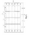
- FIG. 6is a view showing an example display screen that can be used to display ultrasonic images generated using the ultrasonic imaging probe of FIG. 2 ;
- FIG. 7is a view showing a number of ultrasonic images generated on the display screen of FIG. 6 .
- FIG. 1is a functional block diagram showing a medical system 10 in accordance with an illustrative embodiment.
- the system 10illustratively an ultrasonic cardiac imaging system for imaging the treatment of a heart 12 , includes a combined ablation and ultrasonic imaging probe 14 , a therapy module 16 for mapping and treating the heart 12 , an ultrasound imaging module 18 for generating high resolution ultrasonic images (e.g., B-mode images) of anatomical structures (e.g., body tissue) in or near the heart 12 , and a user interface 20 configured for use by the physician 22 in controlling therapy provided by the probe 14 , visualizing anatomical structures and/or other devices within the body, and/or determining the location and orientation of the probe 14 within the body.
- the system 10comprises an ultrasonic imaging system that can be used in monitoring RF ablation therapy provided to a patient's heart 12 or in a cardiac vessel leading into or from the heart 12 .
- the therapy module 16is used for identifying and treating a target tissue site or multiple sites within the body such as an aberrant conductive pathway.
- the therapy module 16comprises a radio frequency (RF) generator 24 that supplies an RF signal 26 to one or more ablation electrodes 28 located on a distal tip of the probe, and a mapping processor 30 that can be used to identify one or more potential therapeutic sites in or near the heart 12 .
- the RF generator 24is configured to deliver ablation energy to each ablation electrode 28 in a controlled manner to ablate any sites identified by the mapping processor 30 .
- Other types of ablation sourcesin addition to or in lieu of the RF generator 24 can also be used for ablating target sites. Examples of other types of ablation sources can include, but are not limited to, microwave generators, acoustic generators, cryoablation generators, and laser/optical generators.
- the probe 14further includes one or more mapping electrodes 32 coupled to the mapping processor 30 .
- the mapping processor 30detects and analyzes electrical signals within the myocardial tissue in order to identify potential treatment sites for ablation using the probe 14 .
- the ablation electrode 28 or multiple ablation electrodes 28can be used for performing both mapping and ablation functions.
- the electrode 28is a dedicated ablation electrode, and one or more separate electrodes 32 on the probe 14 can be tasked to perform mapping functions.
- a separate mapping catheteris used to map potential ablation sites within the body.
- the mapping processor 30is configured to derive activation times and voltage distribution from the electrical signals 34 obtained from each mapping electrode 32 to determine the presence of irregular electrical activity within the heart 12 , which can then be graphically displayed as a map on the user interface 20 . Further details regarding electrophysiology mapping are provided, for example, in U.S. Pat. Nos. 5,485,849, 5,494,042, 5,833,621, and 6,101,409, each of which are expressly incorporated herein by reference in their entirety for all purposes.
- the ultrasound imaging module 18includes an imaging controller 36 coupled to a number of ultrasonic imaging sensors 38 on the probe 14 .
- An ultrasonic signal generator 40is configured to provide one or more control signals 42 for controlling each of the ultrasonic sensors 38 .
- the imaging signals 44 received back from the ultrasonic sensors 38are fed to an image processor 46 , which processes the electrical signals 44 received back from the ultrasonic sensors 38 and generates a number of images, which as is discussed further herein, can be assembled together and displayed as a composite image on the user interface 20 to assist the physician 22 with inserting the probe 14 into position at a target location within the body and to perform an ablation procedure.
- the ultrasonic images obtained via the ultrasound imaging module 18can be used to confirm tissue contact of the probe 14 with the heart 12 or surrounding anatomy, to determine the orientation of the probe 14 within the body, to determine the tissue depth of the tissue at a target ablation site, and/or to visualize the progression of a lesion being formed in the tissue.
- the imaging controller 36is configured to control the ultrasonic sensors 38 to generate ultrasonic images using a pulse-echo imaging technique, in which ultrasonic waves are transmitted by the ultrasonic sensors 38 in a transmit mode into the surrounding body, and the reflected waves are sensed by the ultrasonic sensors 38 operating in a receive mode.
- the control signals 42 used for generating ultrasonic wavesare applied to each of the ultrasonic sensors 38 simultaneously.
- a switching element 48such as a microswitch or MUX can be controlled to selectively activate only a subset of the ultrasonic sensors 38 .
- the ultrasound controller 30can control the switching element 48 to selectively activate each individual ultrasonic sensor 38 in a sequence or pattern.
- each ultrasonic sensor 38may help to reduce or prevent interference with the reflected ultrasonic waves received from other sensors 38 , which helps to reduce cross-talk or other undesired artifacts in the imaging signal 44 .
- the sequential activation of the ultrasonic sensors 38may permit the field of view of the ultrasonic sensors 38 to be overlapped slightly without causing interference in the imaging signals 44 .
- tissue boundariese.g., blood or other bodily fluid
- lesion formation and progressione.g., lesion formation and progression
- other characteristics of the tissuee.g., blood or other bodily fluid
- Example tissue characteristics that can be visualized using the probe 14include, but are not limited to, the presence of fluid vaporization inside the tissue, the existence of a prior scar, and the size and shape of a lesion being formed.
- the depth at which the ultrasonic sensors 38 can visualize anatomical structures within the bodyis dependent on the mechanical characteristics of the elements 38 , the electrical characteristics of the transducer circuitry including the drive frequency of the control signal 42 provided by the signal generator 40 , the boundary conditions and degree of attenuation between the ultrasonic sensors 38 and the surrounding anatomy, as well as other factors.
- the imaging signals 44 sensed by each ultrasonic sensor 38are fed to the imaging processor 46 , which generates ultrasonically derived information that can be displayed on a display monitor 50 of the user interface.
- the imaging processor 46uses the imaging signals 44 to produce a number of images 48 on the display monitor 50 .
- Other ultrasonically derived informationcan also be displayed on the display monitor 50 in conjunction with, or in lieu of, the images 48 .
- an image merger 52is configured to superimpose graphical information obtained from the imaging module 18 and superimpose that information on the display monitor 50 along with graphical information acquired from other sources (e.g., a fluoroscopic monitor) and/or position information from the therapy module 16 to form a composite medical image.
- the imaging processor 46may further superimpose colors, labels, and/or other artifacts onto the images 48 for identifying features within the images.
- the imaging processor 46may superimpose a first color (e.g., green) onto the images 48 to indicate the location where the distal tip section 60 of the probe 14 is near or in contact with the body tissue to be ablated and a second color (e.g., red) to indicate body tissue located further away from the distal tip section 60 .
- a first colore.g., green
- a second colore.g., red
- flashing colors or other features on the display monitor 50may utilized for qualitatively and/or quantitatively assessing contact with the body tissue.
- the images received from each sensor 38 as well as other ultrasonically derived informationcan be arranged side-by-side on the display monitor 50 , allowing the physician to quickly assess factors such as the contact site, tip/tissue orientation, lesion formation and progression, and tissue wall thickness (e.g., in thin-walled anatomical structures).
- the image 48could be displayed, for example, on an existing monitor in an EP lab, on a dedicated display monitor, or simultaneously at multiple locations.
- system 10is described in the context of a medical system for use in intracardiac electrophysiology procedures for diagnosing and treating the heart, in other embodiments the system 10 may be used for treating, diagnosing, or otherwise visualizing other anatomical structures such as the prostate, brain, gall bladder, uterus, esophagus, and/or other regions in the body.
- FIG. 1many of the elements in FIG. 1 are functional in nature, and are not meant to limit the structure that performs these functions in any manner.
- several of the functional blockscan be embodied in a single device, or one or more of the functional blocks can be embodied in multiple devices.
- FIG. 2is a schematic view showing a combined ablation and ultrasonic imaging probe 54 in accordance with an illustrative embodiment for use with the system 10 of FIG. 1 .
- the probe 54comprises a catheter body including an elongate tubular housing 56 having a proximal section 58 and a distal tip section 60 .
- the proximal section 58 of the housing 56is coupled to a proximal hub 62 , which includes a fluid port 64 for providing acoustic coupling/cooling fluid to the distal tip section 60 of the probe 54 .
- the proximal hub 62is electrically connected to both the therapy module 16 and the ultrasonic imaging module 18 , as shown.
- the probe 54includes one or more dedicated mapping electrodes 66 , 68 that can be used to record cardiac electrical signals, and in some cases also the delivery of electrical signals to the patient.
- the electrodes 66 , 68can also be used to facilitate position tracking of the catheter 54 using a position tracking system.
- FIG. 3is a schematic view showing the distal tip section 60 of the probe 54 in greater detail.
- the distal tip section 60 of the probe 54includes an RF ablation electrode 70 and a plurality of ultrasonic imaging sensors 72 , 74 , 76 , 78 .
- the RF ablation electrode 70comprises a conductive material such as platinum, which in addition to serving as an electrode for providing ablation therapy, may also be used as a fluoroscopic marker to determine the location of the distal tip section 60 within the body using fluoroscopy.
- the ultrasonic imaging probe 54includes a distal ultrasonic imaging sensor 72 located at a distal end 74 of the probe 54 .
- the ultrasonic sensor 72is configured to transmit and receive ultrasonic waves primarily in a forward direction away from the distal end 74 of the probe 54 .
- a second set of ultrasonic imaging sensors 76 , 78 , 80 located on a curved portion of the distal tip section 60 proximal to the distal-facing ultrasonic imaging sensor 74are configured to transmit and receive ultrasonic waves both laterally and in a forward direction away from the distal end 74 of the probe 54 .
- the ultrasonic sensors 72 , 76 , 78 , 80each comprise piezoelectric transducers formed of a polymer such as PVDF or a piezoceramic material such as PZT, and are inset within an exposed portion of the RF ablation electrode 70 .
- a number of leads (not shown) extending through the interior space of the probe 54connect the ultrasonic sensors 72 , 76 , 78 , 80 to the ultrasonic imaging module 18 .
- each of the ultrasonic sensors 72 , 76 , 78 , 80are configured to operate in alternating pulsing and sensing modes.
- the ultrasonic sensors 72 , 76 , 78 , 80When excited electrically in the pulsing mode, the ultrasonic sensors 72 , 76 , 78 , 80 generate pressure waves which travel through the electrode 70 and into the surrounding environment.
- the ultrasonic sensors 72 , 76 , 78 , 80each produce an electrical signal as a result of receiving acoustic waves reflected back to the sensors 72 , 76 , 78 , 80 , which are then processed and displayed on the display monitor 50 of the user interface 20 . These reflections are generated by the acoustic waves traveling through changes in density in the surrounding environment being imaged.
- FIG. 4is an end view showing the distal tip section 60 of FIG. 2 in greater detail.
- the ultrasonic imaging probe 54includes three ultrasonic sensors 76 , 78 , 80 equally spaced at an angle ⁇ of 120° about the circumference of the distal tip section 60 at a location proximal to the distal ultrasonic sensor 72 .
- three ultrasonic sensors 76 , 78 , 80are shown in the embodiment of FIG. 4 , a greater or lesser number of ultrasonic sensors may be employed.
- each ultrasonic sensor 72 , 76 , 78 , 80may be disposed at equidistant angles ⁇ of 90° about the circumference of the distal tip section 60 at a location proximal to the distal ultrasonic sensor 72 .
- the use of multiple ultrasonic sensors 76 , 78 , 80 spaced about the circumference of the distal tip section 60ensures that at least one of the sensors 76 , 78 , 80 is in close proximity to the target tissue irrespective of the tip orientation relative to the target tissue.
- Such configurationalso permits the physician to easily visualize the target tissue without having to rotate the probe 54 once the probe 54 is in contact with the tissue.
- the location and relative position(s) of each ultrasonic sensor 72 , 76 , 78 , 80can vary from that shown in FIG. 4 .
- an acoustically transparent window or aperture 82 , 84 , 86 , 88 within the electrode 70facilitates the transmission of ultrasonic waves from the ultrasonic sensors 72 , 76 , 78 , 80 into the surrounding anatomy.
- an acoustic coupling fluid within the interior space of the distal tip section 60serves to couple the acoustic energy transmitted and received via the ultrasonic sensors 72 , 76 , 78 , 80 to the anatomy surrounding the probe 54 .
- each of the proximally-positioned ultrasonic sensors 76 , 78 , 80may be located on a curved portion 82 of the ablation electrode 72 , and are oriented such that the ultrasonic waves are transmitted at a slightly forward angle ⁇ of between about 10° to about 60° relative to a line perpendicular to the longitudinal axis L of the probe 54 .
- the off-set orientation of the proximally-positioned ultrasonic sensors 76 , 78 , 80directs the ultrasonic waves in a slight forward direction, allowing the physician to better view anatomy and objects that are located at or near the distal end 74 .
- FIG. 5is a flow diagram showing an illustrative process 92 for visualizing anatomical structures within the body using a combined ablation and ultrasonic imaging probe.
- FIG. 5may represent, for example, several exemplary steps that can be used during an ablation procedure to visualize a target ablation site (e.g., myocardial tissue) using the ultrasonic imaging probe 54 of FIG. 2 with the imaging system 10 of FIG. 1 .
- a target ablation sitee.g., myocardial tissue
- the process 92may begin generally at block 94 , in which the ultrasonic imaging probe 54 is inserted into the body and advanced intravascularly to an area of interest within the body.
- the probe 54may be inserted into the body via an artery or vein (e.g., the femoral artery) and advanced through the body under fluoroscopic guidance to an area of interest such as the fossa ovalis of the right atrium.
- the physicianmay activate the ultrasonic imaging module 18 to generate images of the distal tip section 60 and the surrounding anatomy using one or more of the ultrasonic sensors 72 , 76 , 78 , 80 (block 96 ).
- each of the ultrasonic sensorsare activated continuously and simultaneously, generating multiple, simultaneous images.
- the ultrasonic imaging module 18may selectively activate the ultrasonic sensors in a sequence or pattern, generating multiple images each at a slightly different time.
- each of the ultrasonic sensorscan be assembled together into a composite image that can be displayed on a display screen, allowing the physician to quickly ascertain the location of the ablation electrode relative to the target tissue (block 98 ).
- each of the images from the ultrasonic sensorscan be used to generate a number of B-mode acoustic images of the area of interest.
- An example view showing a number of ultrasonic images that can be displayed on a display screenis further shown and described with respect to FIG. 7 .
- the ultrasonic imagescan be combined with images from a fluoroscope, CT-scan, MRI-scan, and/or other source to obtain a composite image (block 100 ).
- the operation of one or more of the ultrasonic sensorscan be adjusted to the specific imaging/detection distance required for the specific application (block 102 ).
- the ultrasonic imaging module 18can be configured to adjust the drive frequency of the ultrasonic drive signals to generate ultrasonic waves that penetrate a distance of between about 2 millimeters to 7 millimeters, and more specifically, about 5 millimeters into the tissue, which is the penetration depth typically needed to visualize and asses the formation of lesions in cardiac tissue.
- the ultrasonic imaging module 18can adjust the operating characteristics of each ultrasonic sensor 72 , 76 , 78 , 80 automatically based on a database of ablation procedure scenarios pre-programmed within the imaging module 18 .
- the therapy module 16can be operated to record electrical activity within the heart and derive mapping data (block 104 ). If an aberrant region is identified via the mapping processor 30 , the distal tip section 60 of the probe 54 can be placed into contact with the targeted ablation region (block 106 ). In some procedures, the images produced by the ultrasonic sensors 72 , 76 , 78 , 80 can be used to confirm whether the probe 54 is in direct contact with the tissue to be treated. Once in position, the RF generator 24 is then operated to begin ablating the tissue (block 108 ). If necessary, the physician may readjust the positioning of the probe 54 until the ablation is complete. The process can then be performed for any additional target tissue sites that are identified.
- FIG. 6is a view showing an example screen 110 that can be used to display ultrasonic images generated using the ultrasonic imaging probe 54 of FIG. 2 and the user interface 20 of FIG. 1 .
- the display screen 98includes a number of image panes 112 , 114 , 116 , 118 each corresponding to a separate image generated by one of the ultrasonic sensors 72 , 76 , 78 , 80 .
- the image panes 112 , 114 , 116 , 118are arranged side-by-side with a first image pane 112 representing a B-mode ultrasonic image generating with the distal ultrasonic sensor 72 , and a series of three image panes 114 , 116 , 118 that may be used to display a separate B-mode ultrasonic image generated by a corresponding one of the ultrasonic sensors 76 , 78 , 80 located on the probe 54 proximal to the distal ultrasonic sensor 72 .
- a series of labels 120 , 122 , 124 , 126 located adjacent to each image pane 112 , 114 , 116 , 118provides the physician with information regarding which ultrasonic sensor on the probe 54 corresponds to the image.
- Label “T” on the display screen 110may represent that the distal tip transducer 72 on the probe 54 whereas labels “1,” “2,” and “3” may represent ultrasonic sensors 76 , 78 , and 80 , respectively.
- a set of reference lines 128 located on each pane 112 , 114 , 116 , 118 of the display screen 110provide information regarding the depth at which the image is taken relative to the ultrasonic sensor 72 , 76 , 78 , 80 .
- a set of reference numbers “1 mm,” “2 mm,” “3 mm,” “4 mm,” “5 mm”may be located adjacent to each image pane 112 , 114 , 116 , 118 , providing the physician with information regarding the depth at which the ultrasonic image was taken.
- the number of image panes 112 , 114 , 116 , 118may vary depending on the number of ultrasonic sensors 72 , 76 , 78 , 80 present on the probe 54 . In those embodiments in which the ultrasonic sensors 72 , 76 , 78 , 80 are sequentially timed during each cycle, the image panes 112 , 114 , 116 , 118 may be arranged such that the first image taken during each cycle (e.g., from the distal tip sensor 72 ) is located on the left-hand side of the display screen 110 , and each successive image taken during an imaging cycle is displayed time-wise from left to right on the display screen 110 .
- the first image taken during each cyclee.g., from the distal tip sensor 72
- each successive image taken during an imaging cycleis displayed time-wise from left to right on the display screen 110 .
- FIG. 7is a view showing an example of a number of B-mode ultrasound images generated on the display monitor screen 110 of FIG. 6 .
- FIG. 7may represent, for example, a number of ultrasonic images taken with the ultrasonic imaging probe 54 of FIG. 2 during a cardiac ablation procedure in or near a patient's heart.
- a first B-mode image 130 in the first image pane 112is displayed, indicating the presence of bodily tissue located at a depth of approximately 1.5 millimeters away from the distal tip ultrasonic sensor 72 , and extending to a depth of approximately 2.0 millimeters.
- the lower portion of the image 130represents the location at which the distal end 74 of the ablation electrode 70 contacts the bodily tissue, and may be demarcated on the screen 110 by highlighting, shading, or other visual feature.
- An upper portion of the image 130can be used by the physician to gauge the depth of the anatomical structure, allowing the physician to quickly ascertain what anatomical structure is being imaged.
- two distinct B-mode ultrasonic images 132 , 134are displayed on a second image pane 114 , indicating the presence of multiple anatomical structures located in the acoustic path of one of the ultrasonic sensors (e.g., sensor 76 ).
- a first ultrasonic image 132 located on the image pane 114may represent, for example, the presence of body tissue (e.g., a first vessel) immediately adjacent to the ablation electrode 70 at the location of ultrasonic sensor 76 .
- a second ultrasonic image 134 located on the image pane 114may represent the presence of a second anatomical structure feature (e.g., a second vessel) located further away from the ablation electrode 70 in the path of the ultrasonic sensor 76 .
- the same anatomical structuremay also appear on another B-mode ultrasonic image 136 displayed on a third image pane 116 .
- the physiciancan quickly and easily determine the orientation of the distal tip section 60 relative to the target ablation area without having to rotate the probe 54 within the body, and without the use of position tracking sensors.
- the presence of the ultrasonic image 132 from about 0 millimeters to about 2 millimeters on image pane 114indicates that a side of the ablation electrode 70 is in direct contact with the body tissue, and is aligned closest to ultrasonic sensor 76 . From this information, the physician can quickly determine the location of the tissue relative to the ablation electrode 70 , and can perform the ablation procedure under direct visualization using the ultrasound images.
Landscapes
- Health & Medical Sciences (AREA)
- Life Sciences & Earth Sciences (AREA)
- Medical Informatics (AREA)
- Biophysics (AREA)
- Nuclear Medicine, Radiotherapy & Molecular Imaging (AREA)
- Pathology (AREA)
- Radiology & Medical Imaging (AREA)
- Engineering & Computer Science (AREA)
- Biomedical Technology (AREA)
- Heart & Thoracic Surgery (AREA)
- Physics & Mathematics (AREA)
- Molecular Biology (AREA)
- Surgery (AREA)
- Animal Behavior & Ethology (AREA)
- General Health & Medical Sciences (AREA)
- Public Health (AREA)
- Veterinary Medicine (AREA)
- Gynecology & Obstetrics (AREA)
- Cardiology (AREA)
- Ultra Sonic Daignosis Equipment (AREA)
- Surgical Instruments (AREA)
Abstract
Description
This application claims priority to U.S. Provisional Application No. 61/491,944, filed Jun. 1, 2011, and entitled “ABLATION PROBE WITH ULTRASONIC IMAGING CAPABILITIES,” which is incorporated herein by reference in its entirety for all purposes.
The present disclosure relates generally to devices and systems for imaging anatomical structures within the body. More specifically, the present disclosure relates to an ablation probe with ultrasonic imaging capabilities.
In ablation therapy, it is often necessary to determine various characteristics of body tissue at a target ablation site within the body. In interventional cardiac electrophysiology (EP) procedures, for example, it is often necessary for the physician to determine the condition of cardiac tissue at a target ablation site in or near the heart. During some EP procedures, the physician may deliver a mapping catheter through a main vein or artery into an interior region of the heart to be treated. Using the mapping catheter, the physician may then determine the source of a cardiac rhythm disturbance or abnormality by placing a number of mapping elements carried by the catheter into contact with the adjacent cardiac tissue and then operate the catheter to generate an electrophysiology map of the interior region of the heart. Once a map of the heart is generated, the physician may then advance an ablation catheter into the heart, and position an ablation electrode carried by the catheter tip near the targeted cardiac tissue to ablate the tissue and form a lesion, thereby treating the cardiac rhythm disturbance or abnormality. In some techniques, the ablation catheter itself may include a number of mapping electrodes, allowing the same device to be used for both mapping and ablation.
Various ultrasound-based imaging catheters and probes have been developed for directly visualizing body tissue in applications such as interventional cardiology, interventional radiology, and electrophysiology. For interventional cardiac electrophysiology procedures, for example, ultrasound imaging devices have been developed that permit the visualization of anatomical structures of the heart directly and in real-time. In some electrophysiology procedures, for example, ultrasound catheters may be used to image the intra-atrial septum, to guide transseptal crossing of the atrial septum, to locate and image the pulmonary veins, and to monitor the atrial chambers of the heart for signs of a perforation and pericardial effusion.
Many ultrasound-based imaging systems comprise an imaging probe that is separate from the mapping and ablation catheters used to perform therapy on the patient. As a result, a position tracking system is sometimes used to track the location of each device within the body. In some procedures, it may be difficult for the physician to quickly and accurately determine the condition of tissue to be ablated. Moreover, the images obtained using many ultrasound-based imaging systems are often difficult to read and understand without reference to images obtained from a separate imaging system such as a fluoroscopic imaging system.
The present disclosure relates to devices and systems for imaging an ablation probe within the body. In Example 1, a combined ablation and ultrasound imaging probe for insertion within a body comprises: a housing having a proximal section and a distal tip section; an ablation electrode located at the distal tip section; a first ultrasonic imaging sensor located on the distal tip section, the first ultrasonic imaging sensor configured to transmit acoustic waves in a first direction distal to the distal tip section; and a plurality of second ultrasonic imaging sensors located on the distal tip section proximal to the first ultrasonic imaging sensor, each of the second ultrasonic imaging sensors configured to transmit an acoustic wave in a second direction different from the first direction.
In Example 2, the probe according to Example 1, wherein the ablation electrode comprises an RF ablation electrode.
In Example 3, the probe according to any of Examples 1-2, wherein each of the first and second ultrasonic imaging sensors are disposed within the distal tip section.
In Example 4, the probe according to any of Examples 1-3, wherein the first ultrasonic imaging sensor comprises a distal-facing ultrasonic imaging sensor located at a distal end of the distal tip section.
In Example 5, the probe according to any of Examples 1-4, wherein each of the second ultrasonic imaging sensors are coupled to a curved portion of the distal tip section.
In Example 6, the probe according to Example 5, wherein each of the second ultrasonic imaging sensors are configured to transmit acoustic waves at an angle of between about 10° to about 60° relative to a line perpendicular to a longitudinal axis of the housing.
In Example 7, the probe according to any of Examples 1-6, wherein the second ultrasonic imaging sensors are radially disposed about a circumference of the distal tip section.
In Example 8, the probe according to Example 7, wherein the second ultrasonic imaging sensors are radially spaced at equidistant intervals from each other about the circumference.
In Example 9, the probe according to any of Examples 1-8, wherein the probe further includes at least one mapping electrode.
In Example 10, an ablation and ultrasound imaging system comprises: a probe including a housing with a proximal section and a distal tip section, an ablation electrode, and a plurality of ultrasonic imaging sensors; the plurality of ultrasonic imaging sensors including a first ultrasonic imaging sensor located on the distal tip section and a plurality of second ultrasonic imaging sensors located on the distal tip section proximal to the first ultrasonic imaging sensor; an ablation therapy module configured for generating and supplying an electrical signal to the ablation electrode; an ultrasound imaging module configured for processing ultrasonic imaging signals received from the ultrasonic imaging sensors; and a user interface configured for displaying ultrasonically derived information generated by the ultrasonic imaging sensors on a display screen.
In Example 11, the system according to Example 10, wherein the first ultrasonic imaging sensor comprises a distal-facing ultrasonic imaging sensor disposed at a distal end of the distal tip section.
In Example 12, the system according to any of Examples 10-12, wherein each of the second ultrasonic imaging sensors are coupled to a curved portion of the distal tip section.
In Example 13, the system according to any of Examples 10-12, wherein the ultrasonic imaging module comprises: an imaging controller including an ultrasonic signal generator configured to generate control signals for controlling each ultrasonic imaging sensor; and an image processor configured for processing electrical signals received from each ultrasonic imaging sensor and generating a plurality of ultrasonic images.
In Example 14, the system according to any of Examples 10-13, further comprising a mapping processor in communication with one or more mapping electrodes on the probe.
In Example 15, the system according to any of Examples 10-14, wherein the display screen includes a plurality of imaging panes each configured for displaying an image associated with an associated ultrasonic imaging sensor.
In Example 16, the system according to Example 15, wherein the plurality of imaging panes are displayed in a side-by-side configuration on the display screen.
In Example 17, the system according to Example 15, wherein each imaging pane includes a B-mode ultrasonic image.
In Example 18, a user interface for displaying a composite image generated from an ablation probe with multiple ultrasonic imaging sensors comprises: a display screen including a plurality of imaging panes each configured to display an ultrasonic image generated from an associated one of the ultrasonic imaging sensors; wherein each of the imaging panes are arranged side-by-side to form a composite ultrasonic image from each of the ultrasonic imaging sensors.
In Example 19, the user interface according to Example 18, wherein the ultrasonic images are B-mode images.
In Example 20, the user interface according to any of Examples 18-19, wherein the display screen includes a set of reference numbers indicating an imaging depth of the images generated by each ultrasonic imaging sensor.
While multiple embodiments are disclosed, still other embodiments of the present invention will become apparent to those skilled in the art from the following detailed description, which shows and describes illustrative embodiments of the invention. Accordingly, the drawings and detailed description are to be regarded as illustrative in nature and not restrictive.
While the invention is amenable to various modifications and alternative forms, specific embodiments have been shown by way of example in the drawings and are described in detail below. The intention, however, is not to limit the invention to the particular embodiments described. On the contrary, the invention is intended to cover all modifications, equivalents, and alternatives falling within the scope of the invention as defined by the appended claims.
Thetherapy module 16 is used for identifying and treating a target tissue site or multiple sites within the body such as an aberrant conductive pathway. In the embodiment ofFIG. 1 , thetherapy module 16 comprises a radio frequency (RF)generator 24 that supplies anRF signal 26 to one ormore ablation electrodes 28 located on a distal tip of the probe, and amapping processor 30 that can be used to identify one or more potential therapeutic sites in or near theheart 12. TheRF generator 24 is configured to deliver ablation energy to eachablation electrode 28 in a controlled manner to ablate any sites identified by themapping processor 30. Other types of ablation sources in addition to or in lieu of theRF generator 24 can also be used for ablating target sites. Examples of other types of ablation sources can include, but are not limited to, microwave generators, acoustic generators, cryoablation generators, and laser/optical generators.
In some embodiments, theprobe 14 further includes one ormore mapping electrodes 32 coupled to themapping processor 30. During operation, themapping processor 30 detects and analyzes electrical signals within the myocardial tissue in order to identify potential treatment sites for ablation using theprobe 14. In some embodiments, theablation electrode 28 ormultiple ablation electrodes 28 can be used for performing both mapping and ablation functions. In other embodiments, theelectrode 28 is a dedicated ablation electrode, and one or moreseparate electrodes 32 on theprobe 14 can be tasked to perform mapping functions. In other embodiments, a separate mapping catheter is used to map potential ablation sites within the body.
Themapping processor 30 is configured to derive activation times and voltage distribution from theelectrical signals 34 obtained from eachmapping electrode 32 to determine the presence of irregular electrical activity within theheart 12, which can then be graphically displayed as a map on theuser interface 20. Further details regarding electrophysiology mapping are provided, for example, in U.S. Pat. Nos. 5,485,849, 5,494,042, 5,833,621, and 6,101,409, each of which are expressly incorporated herein by reference in their entirety for all purposes.
In the embodiment ofFIG. 1 , theultrasound imaging module 18 includes animaging controller 36 coupled to a number ofultrasonic imaging sensors 38 on theprobe 14. Anultrasonic signal generator 40 is configured to provide one or more control signals42 for controlling each of theultrasonic sensors 38. The imaging signals44 received back from theultrasonic sensors 38, in turn, are fed to animage processor 46, which processes theelectrical signals 44 received back from theultrasonic sensors 38 and generates a number of images, which as is discussed further herein, can be assembled together and displayed as a composite image on theuser interface 20 to assist thephysician 22 with inserting theprobe 14 into position at a target location within the body and to perform an ablation procedure. In some embodiments, for example, the ultrasonic images obtained via theultrasound imaging module 18 can be used to confirm tissue contact of theprobe 14 with theheart 12 or surrounding anatomy, to determine the orientation of theprobe 14 within the body, to determine the tissue depth of the tissue at a target ablation site, and/or to visualize the progression of a lesion being formed in the tissue.
Theimaging controller 36 is configured to control theultrasonic sensors 38 to generate ultrasonic images using a pulse-echo imaging technique, in which ultrasonic waves are transmitted by theultrasonic sensors 38 in a transmit mode into the surrounding body, and the reflected waves are sensed by theultrasonic sensors 38 operating in a receive mode. In some embodiments, the control signals42 used for generating ultrasonic waves are applied to each of theultrasonic sensors 38 simultaneously. Alternatively, and in other embodiments, a switchingelement 48 such as a microswitch or MUX can be controlled to selectively activate only a subset of theultrasonic sensors 38. In one embodiment, for example, theultrasound controller 30 can control the switchingelement 48 to selectively activate each individualultrasonic sensor 38 in a sequence or pattern. During imaging, the sequential activation of eachultrasonic sensor 38 may help to reduce or prevent interference with the reflected ultrasonic waves received fromother sensors 38, which helps to reduce cross-talk or other undesired artifacts in theimaging signal 44. In some embodiments, the sequential activation of theultrasonic sensors 38 may permit the field of view of theultrasonic sensors 38 to be overlapped slightly without causing interference in the imaging signals44.
Various characteristics associated with theultrasonic sensors 38 as well as the circuitry within theultrasound imaging module 18 can be controlled to optimize the suitability of theultrasonic sensors 38 to accurately detect tissue boundaries (e.g., blood or other bodily fluid), lesion formation and progression, as well as other characteristics of the tissue before, during, and/or after the ablation procedure. Example tissue characteristics that can be visualized using theprobe 14 include, but are not limited to, the presence of fluid vaporization inside the tissue, the existence of a prior scar, and the size and shape of a lesion being formed. The depth at which theultrasonic sensors 38 can visualize anatomical structures within the body is dependent on the mechanical characteristics of theelements 38, the electrical characteristics of the transducer circuitry including the drive frequency of thecontrol signal 42 provided by thesignal generator 40, the boundary conditions and degree of attenuation between theultrasonic sensors 38 and the surrounding anatomy, as well as other factors.
The imaging signals44 sensed by eachultrasonic sensor 38 are fed to theimaging processor 46, which generates ultrasonically derived information that can be displayed on adisplay monitor 50 of the user interface. In some embodiments, theimaging processor 46 uses the imaging signals44 to produce a number ofimages 48 on thedisplay monitor 50. Other ultrasonically derived information can also be displayed on the display monitor50 in conjunction with, or in lieu of, theimages 48.
In some embodiments, animage merger 52 is configured to superimpose graphical information obtained from theimaging module 18 and superimpose that information on the display monitor50 along with graphical information acquired from other sources (e.g., a fluoroscopic monitor) and/or position information from thetherapy module 16 to form a composite medical image. In some embodiments, theimaging processor 46 may further superimpose colors, labels, and/or other artifacts onto theimages 48 for identifying features within the images. For example, and in some embodiments, theimaging processor 46 may superimpose a first color (e.g., green) onto theimages 48 to indicate the location where thedistal tip section 60 of theprobe 14 is near or in contact with the body tissue to be ablated and a second color (e.g., red) to indicate body tissue located further away from thedistal tip section 60. In other embodiments, flashing colors or other features on the display monitor50 may utilized for qualitatively and/or quantitatively assessing contact with the body tissue.
In one embodiment described further with respect toFIGS. 6-7 , the images received from eachsensor 38 as well as other ultrasonically derived information can be arranged side-by-side on thedisplay monitor 50, allowing the physician to quickly assess factors such as the contact site, tip/tissue orientation, lesion formation and progression, and tissue wall thickness (e.g., in thin-walled anatomical structures). Theimage 48 could be displayed, for example, on an existing monitor in an EP lab, on a dedicated display monitor, or simultaneously at multiple locations.
Although thesystem 10 is described in the context of a medical system for use in intracardiac electrophysiology procedures for diagnosing and treating the heart, in other embodiments thesystem 10 may be used for treating, diagnosing, or otherwise visualizing other anatomical structures such as the prostate, brain, gall bladder, uterus, esophagus, and/or other regions in the body. Moreover, many of the elements inFIG. 1 are functional in nature, and are not meant to limit the structure that performs these functions in any manner. For example, several of the functional blocks can be embodied in a single device, or one or more of the functional blocks can be embodied in multiple devices.
In the embodiment ofFIG. 2 , theprobe 54 includes one or morededicated mapping electrodes electrodes catheter 54 using a position tracking system.
In the embodiment shown, theultrasonic imaging probe 54 includes a distalultrasonic imaging sensor 72 located at adistal end 74 of theprobe 54. Theultrasonic sensor 72 is configured to transmit and receive ultrasonic waves primarily in a forward direction away from thedistal end 74 of theprobe 54. A second set ofultrasonic imaging sensors distal tip section 60 proximal to the distal-facingultrasonic imaging sensor 74, in turn, are configured to transmit and receive ultrasonic waves both laterally and in a forward direction away from thedistal end 74 of theprobe 54. In some embodiments, theultrasonic sensors RF ablation electrode 70. A number of leads (not shown) extending through the interior space of theprobe 54 connect theultrasonic sensors ultrasonic imaging module 18.
During ultrasonic imagining, each of theultrasonic sensors ultrasonic sensors electrode 70 and into the surrounding environment. In the sensing mode, theultrasonic sensors sensors user interface 20. These reflections are generated by the acoustic waves traveling through changes in density in the surrounding environment being imaged.
In some embodiments, an acoustically transparent window oraperture electrode 70 facilitates the transmission of ultrasonic waves from theultrasonic sensors distal tip section 60 serves to couple the acoustic energy transmitted and received via theultrasonic sensors probe 54.
In certain embodiments, and as further shown inFIGS. 3 and 4 , each of the proximally-positionedultrasonic sensors curved portion 82 of theablation electrode 72, and are oriented such that the ultrasonic waves are transmitted at a slightly forward angle β of between about 10° to about 60° relative to a line perpendicular to the longitudinal axis L of theprobe 54. During imaging, the off-set orientation of the proximally-positionedultrasonic sensors distal end 74.
Theprocess 92 may begin generally atblock 94, in which theultrasonic imaging probe 54 is inserted into the body and advanced intravascularly to an area of interest within the body. In certain electrophysiology procedures, for example, theprobe 54 may be inserted into the body via an artery or vein (e.g., the femoral artery) and advanced through the body under fluoroscopic guidance to an area of interest such as the fossa ovalis of the right atrium.
With theultrasonic imaging probe 54 positioned at the area of interest, the physician may activate theultrasonic imaging module 18 to generate images of thedistal tip section 60 and the surrounding anatomy using one or more of theultrasonic sensors ultrasonic imaging module 18 may selectively activate the ultrasonic sensors in a sequence or pattern, generating multiple images each at a slightly different time.
The images received from each of the ultrasonic sensors can be assembled together into a composite image that can be displayed on a display screen, allowing the physician to quickly ascertain the location of the ablation electrode relative to the target tissue (block98). In one embodiment, each of the images from the ultrasonic sensors can be used to generate a number of B-mode acoustic images of the area of interest. An example view showing a number of ultrasonic images that can be displayed on a display screen is further shown and described with respect toFIG. 7 . In certain embodiments, the ultrasonic images can be combined with images from a fluoroscope, CT-scan, MRI-scan, and/or other source to obtain a composite image (block100).
Prior to or during ablation, the operation of one or more of the ultrasonic sensors can be adjusted to the specific imaging/detection distance required for the specific application (block102). For cardiac ablation procedures, for example, theultrasonic imaging module 18 can be configured to adjust the drive frequency of the ultrasonic drive signals to generate ultrasonic waves that penetrate a distance of between about 2 millimeters to 7 millimeters, and more specifically, about 5 millimeters into the tissue, which is the penetration depth typically needed to visualize and asses the formation of lesions in cardiac tissue. In some embodiments, theultrasonic imaging module 18 can adjust the operating characteristics of eachultrasonic sensor imaging module 18.
As theprobe 54 is moved around within the heart under direct visualization using theimaging module 18, thetherapy module 16 can be operated to record electrical activity within the heart and derive mapping data (block104). If an aberrant region is identified via themapping processor 30, thedistal tip section 60 of theprobe 54 can be placed into contact with the targeted ablation region (block106). In some procedures, the images produced by theultrasonic sensors probe 54 is in direct contact with the tissue to be treated. Once in position, theRF generator 24 is then operated to begin ablating the tissue (block108). If necessary, the physician may readjust the positioning of theprobe 54 until the ablation is complete. The process can then be performed for any additional target tissue sites that are identified.
A set ofreference lines 128 located on eachpane display screen 110 provide information regarding the depth at which the image is taken relative to theultrasonic sensor image pane
The number ofimage panes ultrasonic sensors probe 54. In those embodiments in which theultrasonic sensors image panes display screen 110, and each successive image taken during an imaging cycle is displayed time-wise from left to right on thedisplay screen 110.
In theexample screen 110 shown inFIG. 7 , a first B-mode image 130 in thefirst image pane 112 is displayed, indicating the presence of bodily tissue located at a depth of approximately 1.5 millimeters away from the distal tipultrasonic sensor 72, and extending to a depth of approximately 2.0 millimeters. The lower portion of theimage 130 represents the location at which thedistal end 74 of theablation electrode 70 contacts the bodily tissue, and may be demarcated on thescreen 110 by highlighting, shading, or other visual feature. An upper portion of theimage 130, in turn, can be used by the physician to gauge the depth of the anatomical structure, allowing the physician to quickly ascertain what anatomical structure is being imaged.
In the example shown, two distinct B-modeultrasonic images second image pane 114, indicating the presence of multiple anatomical structures located in the acoustic path of one of the ultrasonic sensors (e.g., sensor76). A firstultrasonic image 132 located on theimage pane 114 may represent, for example, the presence of body tissue (e.g., a first vessel) immediately adjacent to theablation electrode 70 at the location ofultrasonic sensor 76. A secondultrasonic image 134 located on theimage pane 114, in turn, may represent the presence of a second anatomical structure feature (e.g., a second vessel) located further away from theablation electrode 70 in the path of theultrasonic sensor 76. The same anatomical structure may also appear on another B-modeultrasonic image 136 displayed on athird image pane 116.
From each of theimages distal tip section 60 relative to the target ablation area without having to rotate theprobe 54 within the body, and without the use of position tracking sensors. For example, the presence of theultrasonic image 132 from about 0 millimeters to about 2 millimeters onimage pane 114 indicates that a side of theablation electrode 70 is in direct contact with the body tissue, and is aligned closest toultrasonic sensor 76. From this information, the physician can quickly determine the location of the tissue relative to theablation electrode 70, and can perform the ablation procedure under direct visualization using the ultrasound images.
Various modifications and additions can be made to the exemplary embodiments discussed without departing from the scope of the present invention. For example, while the embodiments described above refer to particular features, the scope of this invention also includes embodiments having different combinations of features and embodiments that do not include all of the described features. Accordingly, the scope of the present invention is intended to embrace all such alternatives, modifications, and variations as fall within the scope of the claims, together with all equivalents thereof.
Claims (18)
1. A combined ablation and ultrasound imaging probe for insertion within a body, the probe comprising:
a housing having a proximal section and a distal tip section;
an ablation electrode located at the distal tip section, the ablation electrode comprising a metal shell, the metal shell having a distal-facing aperture formed through the metal shell and a plurality of lateral-facing apertures formed through the metal shell and located proximal of the distal facing aperture, the plurality of lateral-facing apertures arrayed around a circumference of the metal shell;
a first ultrasonic imaging sensor located at least partially within the metal shell, the first ultrasonic imaging sensor configured to transmit acoustic waves in a first direction through the distal-facing aperture, the first direction orientated primarily distally away from the distal tip section; and
a plurality of second ultrasonic imaging sensors located at least partially within the metal shell and proximal to the first ultrasonic imaging sensor, the plurality of second ultrasonic imaging sensors arrayed about the circumference of the metal shell and configured to transmit acoustic waves through the plurality of lateral-facing apertures in a plurality of second directions, respectively, the plurality of second directions orientated laterally away from the distal tip section and different from the first direction.
2. The probe ofclaim 1 , wherein the ablation electrode comprises an RF ablation electrode.
3. The probe ofclaim 1 , wherein each of the first and second ultrasonic imaging sensors are disposed entirely within the distal tip section.
4. The probe ofclaim 1 , wherein the plurality of apertures are evenly spaced about the circumference of the metal shell.
5. The probe ofclaim 1 , wherein each of the second ultrasonic imaging sensors are located along a curved portion of the metal shell.
6. The probe ofclaim 5 , wherein each of the second ultrasonic imaging sensors are configured to transmit acoustic waves at an angle of between about 10° to about 60° relative to a line perpendicular to a longitudinal axis of the housing.
7. The probe ofclaim 1 , wherein the plurality of second ultrasonic imaging sensors consists of three ultrasonic imaging sensors evenly arrayed at angles of 120° about the circumference of the metal shell.
8. The probe ofclaim 1 , wherein the plurality of second ultrasonic imaging sensors consists of four ultrasonic imaging sensors evenly arrayed at angles of 90° about the circumference of the metal shell.
9. The probe ofclaim 1 , wherein the probe further includes at least one mapping electrode.
10. An imaging and ablation probe for insertion within a body, the probe comprising:
a catheter having a distal tip section;
an ablation electrode located at the distal tip section, the electrode formed from an electrically conductive metal, the electrode having a distal aperture and a plurality of side apertures, all of said apertures formed through the electrically conductive metal of the electrode, the distal aperture distal with respect to each of the plurality of side apertures, the plurality of side apertures arrayed around a circumference of the electrode;
a first ultrasonic imaging sensor located within the electrode and configured to transmit acoustic waves through the distal aperture in a first direction, the first direction orientated primarily distally away from the electrode; and
a plurality of second ultrasonic imaging sensors within the electrode and configured to transmit acoustic waves, the plurality of second ultrasonic imaging sensors directly axially aligned with the plurality of side apertures, respectively, to transmit the transmit acoustic waves through the plurality of side apertures in a plurality of second directions, respectively, the plurality of second directions orientated laterally with respect to a longitudinal axis of the distal tip section.
11. The probe ofclaim 10 , wherein the electrode comprises an RF ablation electrode.
12. The probe ofclaim 10 , wherein each of the first and second ultrasonic imaging sensors are disposed entirely within the electrode.
13. The probe ofclaim 10 , wherein the plurality of side apertures are evenly spaced about the circumference of the electrode.
14. The probe ofclaim 10 , wherein each of the second ultrasonic imaging sensors are located along a curved portion of the electrode.
15. The probe ofclaim 14 , wherein each of the second ultrasonic imaging sensors is configured to transmit acoustic waves at an angle of between about 10° to about 60° relative to a line perpendicular to the longitudinal axis of the distal tip section.
16. The probe ofclaim 10 , wherein the plurality of side apertures consists of three apertures evenly spaced around the circumference of the electrode at angles of 120°.
17. The probe ofclaim 10 , wherein the plurality of side apertures consists of four apertures evenly spaced around the circumference of the electrode at angles of 90°.
18. An imaging and ablation probe for insertion within a body, the probe comprising:
a catheter having a distal tip section;
an RF ablation electrode located at the distal tip section, the RF ablation electrode formed from an electrically conductive metal, the electrode having a distal aperture and a plurality of side apertures, all of said apertures formed through the electrically conductive metal of the electrode, the distal aperture located distal with respect to each of the plurality of side apertures, the plurality of side apertures evenly spaced around a circumference of the electrode;
a first ultrasonic imaging sensor inset within the electrode and configured to transmit acoustic waves in a first direction through the distal aperture, the first direction orientated primarily distally from the electrode; and
a plurality of second ultrasonic imaging sensors inset within the electrode and each directly aimed in one of a plurality of different directions, respectively, and configured to transmit acoustic waves through the plurality of side apertures in the plurality of second directions, respectively, the plurality of second directions laterally directed with respect to the electrode and respectively different from each other and the first direction.
Priority Applications (1)
| Application Number | Priority Date | Filing Date | Title |
|---|---|---|---|
| US13/437,267US9241687B2 (en) | 2011-06-01 | 2012-04-02 | Ablation probe with ultrasonic imaging capabilities |
Applications Claiming Priority (2)
| Application Number | Priority Date | Filing Date | Title |
|---|---|---|---|
| US201161491944P | 2011-06-01 | 2011-06-01 | |
| US13/437,267US9241687B2 (en) | 2011-06-01 | 2012-04-02 | Ablation probe with ultrasonic imaging capabilities |
Publications (2)
| Publication Number | Publication Date |
|---|---|
| US20120310064A1 US20120310064A1 (en) | 2012-12-06 |
| US9241687B2true US9241687B2 (en) | 2016-01-26 |
Family
ID=45953296
Family Applications (1)
| Application Number | Title | Priority Date | Filing Date |
|---|---|---|---|
| US13/437,267Active2033-09-18US9241687B2 (en) | 2011-06-01 | 2012-04-02 | Ablation probe with ultrasonic imaging capabilities |
Country Status (5)
| Country | Link |
|---|---|
| US (1) | US9241687B2 (en) |
| EP (1) | EP2713888B1 (en) |
| JP (1) | JP2014516723A (en) |
| AU (1) | AU2012262959A1 (en) |
| WO (1) | WO2012166239A1 (en) |
Cited By (21)
| Publication number | Priority date | Publication date | Assignee | Title |
|---|---|---|---|---|
| US9603659B2 (en) | 2011-09-14 | 2017-03-28 | Boston Scientific Scimed Inc. | Ablation device with ionically conductive balloon |
| US9743854B2 (en) | 2014-12-18 | 2017-08-29 | Boston Scientific Scimed, Inc. | Real-time morphology analysis for lesion assessment |
| US9757191B2 (en) | 2012-01-10 | 2017-09-12 | Boston Scientific Scimed, Inc. | Electrophysiology system and methods |
| US10201311B2 (en) | 2013-02-08 | 2019-02-12 | Acutus Medical, Inc. | Expandable catheter assembly with flexible printed circuit board (PCB) electrical pathways |
| US10314497B2 (en) | 2011-03-10 | 2019-06-11 | Acutus Medical Inc. | Device and method for the geometric determination of electrical dipole densities on the cardiac wall |
| USD851774S1 (en) | 2012-08-31 | 2019-06-18 | Acutus Medical, Inc. | Set of transducer-electrode pairs for a catheter |
| US10376171B2 (en) | 2006-08-03 | 2019-08-13 | Christoph Scharf | Method and device for determining and presenting surface charge and dipole densities on cardiac walls |
| US10420605B2 (en) | 2012-01-31 | 2019-09-24 | Koninklijke Philips N.V. | Ablation probe with fluid-based acoustic coupling for ultrasonic tissue imaging |
| US10463267B2 (en) | 2008-01-17 | 2019-11-05 | Christoph Scharf | Device and method for the geometric determination of electrical dipole densities on the cardiac wall |
| US10524684B2 (en) | 2014-10-13 | 2020-01-07 | Boston Scientific Scimed Inc | Tissue diagnosis and treatment using mini-electrodes |
| US10593234B2 (en) | 2015-05-12 | 2020-03-17 | Acutus Medical, Inc. | Cardiac virtualization test tank and testing system and method |
| US10603105B2 (en) | 2014-10-24 | 2020-03-31 | Boston Scientific Scimed Inc | Medical devices with a flexible electrode assembly coupled to an ablation tip |
| US10653318B2 (en) | 2015-05-13 | 2020-05-19 | Acutus Medical, Inc. | Localization system and method useful in the acquisition and analysis of cardiac information |
| US10828011B2 (en) | 2013-09-13 | 2020-11-10 | Acutus Medical, Inc. | Devices and methods for determination of electrical dipole densities on a cardiac surface |
| US11278231B2 (en) | 2014-03-25 | 2022-03-22 | Acutus Medical, Inc. | Cardiac analysis user interface system and method |
| US11344366B2 (en) | 2015-05-12 | 2022-05-31 | Acutus Medical, Inc. | Ultrasound sequencing system and method |
| US11399759B2 (en) | 2016-05-03 | 2022-08-02 | Acutus Medical, Inc. | Cardiac mapping system with efficiency algorithm |
| US11684416B2 (en) | 2009-02-11 | 2023-06-27 | Boston Scientific Scimed, Inc. | Insulated ablation catheter devices and methods of use |
| US11707260B2 (en) | 2010-11-18 | 2023-07-25 | Koninklijke Philips N.V. | Medical device with forward and sideward ablation monitoring ultrasound transducers |
| US12178582B2 (en) | 2018-11-09 | 2024-12-31 | Acutus Medical, Inc. | Systems and methods for calculating patient information |
| US12295669B2 (en) | 2019-06-04 | 2025-05-13 | Acutus Medical, Inc. | Systems and methods for performing localization within a body |
Families Citing this family (19)
| Publication number | Priority date | Publication date | Assignee | Title |
|---|---|---|---|---|
| EP3106116B1 (en) | 2009-06-30 | 2018-08-01 | Boston Scientific Scimed, Inc. | Map and ablate open irrigated hybrid catheter |
| US9089340B2 (en) | 2010-12-30 | 2015-07-28 | Boston Scientific Scimed, Inc. | Ultrasound guided tissue ablation |
| WO2013040201A2 (en) | 2011-09-14 | 2013-03-21 | Boston Scientific Scimed, Inc. | Ablation device with multiple ablation modes |
| JP2015506209A (en) | 2011-12-28 | 2015-03-02 | ボストン サイエンティフィック サイムド,インコーポレイテッドBoston Scientific Scimed,Inc. | Ablation probe and ablation and ultrasound imaging system |
| US20140276052A1 (en)* | 2013-03-15 | 2014-09-18 | Philips Koninklijke Electronics N.V. | Ablation catheter with ultrasonic lesion monitoring capability |
| US10716536B2 (en) | 2013-07-17 | 2020-07-21 | Tissue Differentiation Intelligence, Llc | Identifying anatomical structures |
| US10154826B2 (en) | 2013-07-17 | 2018-12-18 | Tissue Differentiation Intelligence, Llc | Device and method for identifying anatomical structures |
| WO2016044411A1 (en)* | 2014-09-17 | 2016-03-24 | Avaz Surgical, Llc | Identifying anatomical structures |
| US10512449B2 (en)* | 2014-09-19 | 2019-12-24 | Volcano Corporation | Intravascular device for vessel measurement and associated systems, devices, and methods |
| EP3878371B1 (en) | 2015-02-27 | 2025-09-17 | Koninklijke Philips N.V. | System for adaptive ablation and therapy based on elastography monitoring |
| KR101683518B1 (en)* | 2015-07-22 | 2016-12-07 | 기아자동차 주식회사 | Contactless durability diagnosis apparatus and method |
| WO2017192510A2 (en) | 2016-05-02 | 2017-11-09 | Affera, Inc. | Pulsed radiofrequency ablation |
| US11986341B1 (en) | 2016-05-26 | 2024-05-21 | Tissue Differentiation Intelligence, Llc | Methods for accessing spinal column using B-mode imaging to determine a trajectory without penetrating the the patient's anatomy |
| US11701086B1 (en) | 2016-06-21 | 2023-07-18 | Tissue Differentiation Intelligence, Llc | Methods and systems for improved nerve detection |
| WO2019100212A1 (en)* | 2017-11-21 | 2019-05-31 | 深圳迈瑞生物医疗电子股份有限公司 | Ultrasonic system and method for planning ablation |
| US11602388B2 (en)* | 2019-08-21 | 2023-03-14 | Veran Medical Technologies, Inc. | Ablation monitoring system and method |
| WO2021126980A1 (en) | 2019-12-16 | 2021-06-24 | Affera, Inc. | Pulmonary vein isolation catheters and associated devices, systems, and methods |
| JP2022152469A (en)* | 2021-03-29 | 2022-10-12 | 吉野川電線株式会社 | Cauterization device |
| USD1014762S1 (en) | 2021-06-16 | 2024-02-13 | Affera, Inc. | Catheter tip with electrode panel(s) |
Citations (248)
| Publication number | Priority date | Publication date | Assignee | Title |
|---|---|---|---|---|
| US3773401A (en) | 1971-05-13 | 1973-11-20 | Siemens Ag | Coherent optical multichannel correlator |
| US4763660A (en) | 1985-12-10 | 1988-08-16 | Cherne Industries, Inc. | Flexible and disposable electrode belt device |
| US5029588A (en) | 1989-06-15 | 1991-07-09 | Cardiovascular Imaging Systems, Inc. | Laser catheter with imaging capability |
| US5240003A (en) | 1989-10-16 | 1993-08-31 | Du-Med B.V. | Ultrasonic instrument with a micro motor having stator coils on a flexible circuit board |
| US5254088A (en) | 1990-02-02 | 1993-10-19 | Ep Technologies, Inc. | Catheter steering mechanism |
| US5331966A (en) | 1991-04-05 | 1994-07-26 | Medtronic, Inc. | Subcutaneous multi-electrode sensing system, method and pacer |
| US5383874A (en) | 1991-11-08 | 1995-01-24 | Ep Technologies, Inc. | Systems for identifying catheters and monitoring their use |
| US5385146A (en) | 1993-01-08 | 1995-01-31 | Goldreyer; Bruce N. | Orthogonal sensing for use in clinical electrophysiology |
| US5385148A (en) | 1993-07-30 | 1995-01-31 | The Regents Of The University Of California | Cardiac imaging and ablation catheter |
| US5391199A (en) | 1993-07-20 | 1995-02-21 | Biosense, Inc. | Apparatus and method for treating cardiac arrhythmias |
| US5398683A (en) | 1991-05-24 | 1995-03-21 | Ep Technologies, Inc. | Combination monophasic action potential/ablation catheter and high-performance filter system |
| US5462521A (en) | 1993-12-21 | 1995-10-31 | Angeion Corporation | Fluid cooled and perfused tip for a catheter |
| US5485849A (en) | 1994-01-31 | 1996-01-23 | Ep Technologies, Inc. | System and methods for matching electrical characteristics and propagation velocities in cardiac tissue |
| US5494042A (en) | 1994-01-28 | 1996-02-27 | Ep Technologies, Inc. | Systems and methods for deriving electrical characteristics of cardiac tissue for output in iso-characteristic displays |
| US5500012A (en) | 1992-07-15 | 1996-03-19 | Angeion Corporation | Ablation catheter system |
| US5571088A (en) | 1993-07-01 | 1996-11-05 | Boston Scientific Corporation | Ablation catheters |
| US5579764A (en) | 1993-01-08 | 1996-12-03 | Goldreyer; Bruce N. | Method and apparatus for spatially specific electrophysiological sensing in a catheter with an enlarged ablating electrode |
| US5582609A (en) | 1993-10-14 | 1996-12-10 | Ep Technologies, Inc. | Systems and methods for forming large lesions in body tissue using curvilinear electrode elements |
| US5647870A (en) | 1993-03-16 | 1997-07-15 | Ep Technologies, Inc. | Multiple electrode support structures |
| US5762067A (en) | 1996-05-30 | 1998-06-09 | Advanced Technology Laboratories, Inc. | Ultrasonic endoscopic probe |
| US5788636A (en) | 1997-02-25 | 1998-08-04 | Acuson Corporation | Method and system for forming an ultrasound image of a tissue while simultaneously ablating the tissue |
| US5800482A (en) | 1996-03-06 | 1998-09-01 | Cardiac Pathways Corporation | Apparatus and method for linear lesion ablation |
| US5830213A (en) | 1996-04-12 | 1998-11-03 | Ep Technologies, Inc. | Systems for heating and ablating tissue using multifunctional electrode structures |
| US5868735A (en) | 1997-03-06 | 1999-02-09 | Scimed Life Systems, Inc. | Cryoplasty device and method |
| US5871483A (en) | 1996-01-19 | 1999-02-16 | Ep Technologies, Inc. | Folding electrode structures |
| WO1999027862A1 (en) | 1997-12-02 | 1999-06-10 | Odyssey Technologies, Inc. | Apparatus and method for cryogenic inhibition of hyperplasia |
| US6004269A (en) | 1993-07-01 | 1999-12-21 | Boston Scientific Corporation | Catheters for imaging, sensing electrical potentials, and ablating tissue |
| JP2000000242A (en) | 1998-03-25 | 2000-01-07 | Sulzer Osypka Gmbh | System and method for visual display of organ activity |
| US6050994A (en) | 1998-05-05 | 2000-04-18 | Cardiac Pacemakers, Inc. | RF ablation apparatus and method using controllable duty cycle with alternate phasing |
| US6059778A (en) | 1998-05-05 | 2000-05-09 | Cardiac Pacemakers, Inc. | RF ablation apparatus and method using unipolar and bipolar techniques |
| US6064905A (en) | 1998-06-18 | 2000-05-16 | Cordis Webster, Inc. | Multi-element tip electrode mapping catheter |
| WO2000029062A2 (en) | 1998-11-12 | 2000-05-25 | Boston Scientific Limited | Method of manufacturing cellulosic structures, and electrode assembly comprising an expandable-collapsible body |
| US6070094A (en) | 1994-10-11 | 2000-05-30 | Ep Technologies, Inc. | Systems and methods for guiding movable electrode elements within multiple-electrode structures |
| US6083170A (en) | 1996-05-17 | 2000-07-04 | Biosense, Inc. | Self-aligning catheter |
| US6101409A (en) | 1995-02-17 | 2000-08-08 | Ep Technologies, Inc. | Systems and methods for analyzing biopotential morphologies in body tissue |
| US6116027A (en) | 1998-09-29 | 2000-09-12 | Air Products And Chemicals, Inc. | Supplemental air supply for an air separation system |
| US6165123A (en) | 1997-08-27 | 2000-12-26 | Pinotage Llc | Controllable multi-directional positioning system |
| US6171305B1 (en) | 1998-05-05 | 2001-01-09 | Cardiac Pacemakers, Inc. | RF ablation apparatus and method having high output impedance drivers |
| US6210337B1 (en) | 1995-06-07 | 2001-04-03 | Atl Ultrasound Inc. | Ultrasonic endoscopic probe |
| US6233491B1 (en) | 1993-03-16 | 2001-05-15 | Ep Technologies, Inc. | Cardiac mapping and ablation systems |
| US6241754B1 (en) | 1993-10-15 | 2001-06-05 | Ep Technologies, Inc. | Composite structures and methods for ablating tissue to form complex lesion patterns in the treatment of cardiac conditions and the like |
| WO2001064145A1 (en) | 2000-03-01 | 2001-09-07 | Innercool Therapies, Inc. | Cooling therapies/device for angioplasty with restenosis |
| US6290697B1 (en) | 1998-12-01 | 2001-09-18 | Irvine Biomedical, Inc. | Self-guiding catheter system for tissue ablation |
| WO2001068173A2 (en) | 2000-03-15 | 2001-09-20 | Boston Scientific Limited | Ablation and imaging catheter |
| WO2002005868A2 (en) | 2000-07-13 | 2002-01-24 | Transurgical, Inc. | Thermal treatment methods and apparatus with focused energy application |
| WO2002009599A2 (en) | 2000-07-31 | 2002-02-07 | Boston Scientific Limited | Expandable atherectomy burr |
| US6352534B1 (en) | 1997-09-30 | 2002-03-05 | Boston Scientific Corporation | Deflectable interstitial ablation device |
| WO2002019934A1 (en) | 2000-09-08 | 2002-03-14 | Atrionx, Inc. | Medical device with sensor cooperating with expandable member |
| US20020087208A1 (en) | 1997-12-03 | 2002-07-04 | Scimed Life Systems, Inc. | Devices and methods for creating lesions in endocardial and surrounding tissue to isolate focal arrhythmia substrates |
| US6423002B1 (en) | 1999-06-24 | 2002-07-23 | Acuson Corporation | Intra-operative diagnostic ultrasound multiple-array transducer probe and optional surgical tool |
| US6475213B1 (en) | 1996-01-19 | 2002-11-05 | Ep Technologies, Inc. | Method of ablating body tissue |
| US6491710B2 (en) | 2000-09-07 | 2002-12-10 | Shutaro Satake | Balloon catheter for pulmonary vein isolation |
| WO2002102234A2 (en) | 2001-06-19 | 2002-12-27 | Eva Corporation | Positioning apparatus for use in repairing a vessel |
| US20030013958A1 (en) | 2001-07-10 | 2003-01-16 | Assaf Govari | Location sensing with real-time ultrasound imaging |
| US6508769B2 (en) | 1999-12-28 | 2003-01-21 | Koninklijke Philips Electronics N.V. | Ultrasonic image processing method and examination system for displaying an ultrasonic color-coded image sequence of an object having moving parts |
| US6508767B2 (en) | 2000-02-16 | 2003-01-21 | Koninklijke Philips Electronics N.V. | Ultrasonic harmonic image segmentation |
| US6516667B1 (en) | 2000-03-07 | 2003-02-11 | Koninklijke Philips Electronics N.V. | Ultrasonic harmonic signal acquisition |
| US6517533B1 (en) | 1997-07-29 | 2003-02-11 | M. J. Swaminathan | Balloon catheter for controlling tissue remodeling and/or tissue proliferation |
| US6537271B1 (en) | 2000-07-06 | 2003-03-25 | Cryogen, Inc. | Balloon cryogenic catheter |
| US6544175B1 (en) | 2000-09-15 | 2003-04-08 | Koninklijke Philips Electronics N.V. | Ultrasound apparatus and methods for display of a volume using interlaced data |
| US6547788B1 (en) | 1997-07-08 | 2003-04-15 | Atrionx, Inc. | Medical device with sensor cooperating with expandable member |
| US20030088240A1 (en) | 2001-11-02 | 2003-05-08 | Vahid Saadat | Methods and apparatus for cryo-therapy |
| US6572549B1 (en) | 2001-12-18 | 2003-06-03 | Koninklijke Philips Electronics Nv | High frame rate extended field of view ultrasound imaging system and method |
| US6575966B2 (en) | 1999-08-23 | 2003-06-10 | Cryocath Technologies Inc. | Endovascular cryotreatment catheter |
| US6579278B1 (en) | 2000-05-05 | 2003-06-17 | Scimed Life Systems, Inc. | Bi-directional steerable catheter with asymmetric fulcrum |
| US6582372B2 (en) | 2001-06-22 | 2003-06-24 | Koninklijke Philips Electronics N.V. | Ultrasound system for the production of 3-D images |
| US6589182B1 (en) | 2001-02-12 | 2003-07-08 | Acuson Corporation | Medical diagnostic ultrasound catheter with first and second tip portions |
| US6592525B2 (en) | 2001-07-31 | 2003-07-15 | Koninklijke Philips Electronics N.V. | Micro-machined ultrasonic transducer (MUT) having improved sensitivity |
| US6602242B1 (en) | 1997-12-01 | 2003-08-05 | Biosense Webster, Inc. | Irrigated tip catheter |
| US20030158548A1 (en) | 2002-02-19 | 2003-08-21 | Phan Huy D. | Surgical system including clamp and apparatus for securing an energy transmission device to the clamp and method of converting a clamp into an electrophysiology device |
| US20030158549A1 (en) | 2002-02-19 | 2003-08-21 | Swanson David K. | Apparatus for securing an electrophysiology probe to a clamp |
| US6620103B1 (en) | 2002-06-11 | 2003-09-16 | Koninklijke Philips Electronics N.V. | Ultrasonic diagnostic imaging system for low flow rate contrast agents |
| US6632179B2 (en) | 2001-07-31 | 2003-10-14 | Koninklijke Philips Electronics N.V. | Acoustic imaging system with non-focusing lens |
| US6640120B1 (en) | 2000-10-05 | 2003-10-28 | Scimed Life Systems, Inc. | Probe assembly for mapping and ablating pulmonary vein tissue and method of using same |
| US6638222B2 (en) | 2000-02-29 | 2003-10-28 | Scimed Life Systems, Inc. | RF ablation and ultrasound catheter for crossing chronic total occlusions |
| US6658279B2 (en) | 1996-10-28 | 2003-12-02 | Ep Technologies, Inc. | Ablation and imaging catheter |
| US6656174B1 (en) | 2000-07-20 | 2003-12-02 | Scimed Life Systems, Inc. | Devices and methods for creating lesions in blood vessels without obstructing blood flow |
| US20030229286A1 (en) | 1999-01-25 | 2003-12-11 | Lenker Jay A. | Resolution optical and ultrasound devices for imaging and treatment of body lumens |
| US6676606B2 (en) | 2002-06-11 | 2004-01-13 | Koninklijke Philips Electronics N.V. | Ultrasonic diagnostic micro-vascular imaging |
| US6692441B1 (en) | 2002-11-12 | 2004-02-17 | Koninklijke Philips Electronics N.V. | System for identifying a volume of interest in a volume rendered ultrasound image |
| US6705992B2 (en) | 2002-02-28 | 2004-03-16 | Koninklijke Philips Electronics N.V. | Ultrasound imaging enhancement to clinical patient monitoring functions |
| US6709396B2 (en) | 2002-07-17 | 2004-03-23 | Vermon | Ultrasound array transducer for catheter use |
| US6735465B2 (en) | 2001-10-24 | 2004-05-11 | Scimed Life Systems, Inc. | Systems and processes for refining a registered map of a body cavity |
| US6736814B2 (en) | 2002-02-28 | 2004-05-18 | Misonix, Incorporated | Ultrasonic medical treatment device for bipolar RF cauterization and related method |
| US6743174B2 (en) | 2002-04-01 | 2004-06-01 | Koninklijke Philips Electronics N.V. | Ultrasonic diagnostic imaging system with automatically controlled contrast and brightness |
| US20040147920A1 (en) | 2002-10-21 | 2004-07-29 | Yaron Keidar | Prediction and assessment of ablation of cardiac tissue |
| US6776758B2 (en) | 2002-10-11 | 2004-08-17 | Koninklijke Philips Electronics N.V. | RFI-protected ultrasound probe |
| US20040162556A1 (en) | 2003-02-14 | 2004-08-19 | Scimed Life Systems, Inc. | Power supply and control apparatus and electrophysiology systems including the same |
| US20040186467A1 (en) | 2003-03-21 | 2004-09-23 | Swanson David K. | Apparatus for maintaining contact between diagnostic and therapeutic elements and tissue and systems including the same |
| US6796979B2 (en) | 2002-12-11 | 2004-09-28 | Cryocor, Inc. | Coaxial catheter system for performing a single step cryoablation |
| US6796980B2 (en) | 2001-11-21 | 2004-09-28 | Cardiac Pacemakers, Inc. | System and method for validating and troubleshooting ablation system set-up |
| US20040215177A1 (en) | 2003-04-24 | 2004-10-28 | Scimed Life Systems, Inc. | Therapeutic apparatus having insulated region at the insertion area |
| US20040215186A1 (en) | 2003-03-03 | 2004-10-28 | Sinus Rhythm Technologies, Inc. | Electrical block positioning devices and methods of use therefor |
| US6811550B2 (en) | 1999-03-15 | 2004-11-02 | Cryovascular Systems, Inc. | Safety cryotherapy catheter |
| US6824517B2 (en) | 2002-06-25 | 2004-11-30 | Koninklijke Philips Electronics N.V. | Ultrasound quantification in real-time using acoustic data in more than two dimensions |
| US6837884B2 (en) | 2001-06-18 | 2005-01-04 | Arthrocare Corporation | Electrosurgical apparatus having compound return electrode |
| US20050033331A1 (en) | 2003-07-28 | 2005-02-10 | Polymorfix, Inc., C/O Medventure Associates | Pyloric valve obstructing devices and methods |
| US20050059963A1 (en) | 2003-09-12 | 2005-03-17 | Scimed Life Systems, Inc. | Systems and method for creating transmural lesions |
| US20050059862A1 (en) | 2003-09-12 | 2005-03-17 | Scimed Life Systems, Inc. | Cannula with integrated imaging and optical capability |
| US20050059962A1 (en) | 2003-09-12 | 2005-03-17 | Scimed Life Systems, Inc. | Ablation catheter with tissue protecting assembly |
| US20050059965A1 (en) | 2003-09-15 | 2005-03-17 | Scimed Life Systems, Inc. | Catheter balloons |
| US20050065506A1 (en) | 2003-09-12 | 2005-03-24 | Scimed Life Systems, Inc. | Vacuum-based catheter stabilizer |
| US20050090817A1 (en) | 2003-10-22 | 2005-04-28 | Scimed Life Systems, Inc. | Bendable endoscopic bipolar device |
| US20050119545A1 (en) | 2003-12-02 | 2005-06-02 | Swanson David K. | Surgical methods and apparatus for maintaining contact between tissue and electrophysiology elements and confirming whether a therapeutic lesion has been formed |
| US20050119649A1 (en) | 2003-12-02 | 2005-06-02 | Swanson David K. | Self-anchoring surgical methods and apparatus for stimulating tissue |
| US20050119648A1 (en) | 2003-12-02 | 2005-06-02 | Swanson David K. | Surgical methods and apparatus for stimulating tissue |
| US20050119653A1 (en) | 2003-12-02 | 2005-06-02 | Swanson David K. | Surgical methods and apparatus for forming lesions in tissue and confirming whether a therapeutic lesion has been formed |
| US20050119654A1 (en) | 2003-12-02 | 2005-06-02 | Swanson David K. | Clamp based methods and apparatus for forming lesions in tissue and confirming whether a therapeutic lesion has been formed |
| US20050124881A1 (en) | 2002-03-18 | 2005-06-09 | Japan Sciemce And Technology Agency | Ultrasonographic system and ultrasonography |
| EP1547537A1 (en) | 2002-08-20 | 2005-06-29 | Toray Industries, Inc. | Catheter for treating irregular heart pulse |
| US6922579B2 (en) | 2002-12-12 | 2005-07-26 | Scimed Life Systems, Inc. | La placian electrode |
| US6932811B2 (en) | 2000-04-27 | 2005-08-23 | Atricure, Inc. | Transmural ablation device with integral EKG sensor |
| US20050187544A1 (en) | 2004-02-19 | 2005-08-25 | Scimed Life Systems, Inc. | Cooled probes and apparatus for maintaining contact between cooled probes and tissue |
| US6945938B2 (en) | 1998-10-02 | 2005-09-20 | Boston Scientific Limited | Systems and methods for evaluating objects with an ultrasound image |
| US6950689B1 (en) | 1998-08-03 | 2005-09-27 | Boston Scientific Scimed, Inc. | Dynamically alterable three-dimensional graphical model of a body region |
| US6952615B2 (en) | 2001-09-28 | 2005-10-04 | Shutaro Satake | Radiofrequency thermal balloon catheter |
| US20050228286A1 (en) | 2004-04-07 | 2005-10-13 | Messerly Jeffrey D | Medical system having a rotatable ultrasound source and a piercing tip |
| US20050228504A1 (en) | 2004-03-26 | 2005-10-13 | Demarais Denise M | Systems and methods for treating obesity |
| US6958040B2 (en) | 2001-12-28 | 2005-10-25 | Ekos Corporation | Multi-resonant ultrasonic catheter |
| US20050273060A1 (en) | 2004-06-03 | 2005-12-08 | Mayo Foundation For Medical Education And Research | Obesity treatment and device |
| US7001383B2 (en) | 2002-10-21 | 2006-02-21 | Biosense, Inc. | Real-time monitoring and mapping of ablation lesion formation in the heart |
| US20060089634A1 (en) | 2002-05-13 | 2006-04-27 | Anderson Neil L | Ablation catheter |
| US7037264B2 (en) | 2000-08-17 | 2006-05-02 | Koninklijke Philips Electronics N.V. | Ultrasonic diagnostic imaging with steered image plane |
| US20060100522A1 (en) | 2004-11-08 | 2006-05-11 | Scimed Life Systems, Inc. | Piezocomposite transducers |
| US7047068B2 (en) | 2000-12-11 | 2006-05-16 | C.R. Bard, Inc. | Microelectrode catheter for mapping and ablation |
| EP1343427B1 (en) | 2000-12-11 | 2006-07-26 | C.R. Bard, Inc. | Apparatus for mapping |
| US7105122B2 (en) | 2002-10-08 | 2006-09-12 | Ossur Hf | Prosthesis socket direct casting device having multiple compression chambers |
| JP2006239414A (en) | 2005-02-14 | 2006-09-14 | Biosense Webster Inc | Irrigated tip catheter and method for producing the same |
| US7112198B2 (en) | 2003-01-24 | 2006-09-26 | Shutaro Satake | Radio-frequency heating balloon catheter |
| EP1717601A2 (en) | 2005-04-26 | 2006-11-02 | Biosense Webster, Inc. | Display of catheter tip with beam direction for ultrasound system |
| US7131947B2 (en) | 2003-05-08 | 2006-11-07 | Koninklijke Philips Electronics N.V. | Volumetric ultrasonic image segment acquisition with ECG display |
| US20060253028A1 (en) | 2005-04-20 | 2006-11-09 | Scimed Life Systems, Inc. | Multiple transducer configurations for medical ultrasound imaging |
| US20060253116A1 (en) | 2005-05-05 | 2006-11-09 | Boaz Avitall | Preshaped localization catheter, system, and method for graphically reconstructing pulmonary vein ostia |
| US20070003811A1 (en) | 2005-06-20 | 2007-01-04 | Elringklinger Ag | Sealing arrangement for a fuel cell stack and process for the production of such a sealing arrangement |
| US20070016059A1 (en) | 2005-07-15 | 2007-01-18 | Atsushi Morimoto | Device and method for shielding an ultrasound probe |
| US20070016054A1 (en) | 2005-07-01 | 2007-01-18 | Scimed Life Systems, Inc. | Medical imaging device having a forward looking flow detector |
| US20070016228A1 (en) | 2005-07-13 | 2007-01-18 | Boston Scientific Scimed, Inc. | Surgical clip applicator and apparatus including the same |
| US7166075B2 (en) | 2002-03-08 | 2007-01-23 | Wisconsin Alumni Research Foundation | Elastographic imaging of in vivo soft tissue |
| US20070021744A1 (en)* | 2005-07-07 | 2007-01-25 | Creighton Francis M Iv | Apparatus and method for performing ablation with imaging feedback |
| US20070073135A1 (en) | 2005-09-13 | 2007-03-29 | Warren Lee | Integrated ultrasound imaging and ablation probe |
| US20070088345A1 (en) | 2005-10-13 | 2007-04-19 | Ust Inc. | Applications of HIFU and chemotherapy |
| US7220233B2 (en) | 2003-04-08 | 2007-05-22 | Flowcardia, Inc. | Ultrasound catheter devices and methods |
| US7232433B1 (en) | 1999-09-22 | 2007-06-19 | Siemens Medical Solutions Usa, Inc. | Medical diagnostic ultrasound catheter with dielectric isolation |
| JP2007163559A (en) | 2005-12-09 | 2007-06-28 | Konica Minolta Business Technologies Inc | Image forming apparatus and control method for image forming apparatus |
| WO2007079278A1 (en) | 2005-12-29 | 2007-07-12 | Boston Scientific Scimed, Inc. | Apparatus for performing therapeutics tissue ablation and brachytherapy |
| US20070167813A1 (en) | 2005-11-30 | 2007-07-19 | Warren Lee | Apparatuses Comprising Catheter Tips, Including Mechanically Scanning Ultrasound Probe Catheter Tip |
| US7247155B2 (en) | 1995-02-22 | 2007-07-24 | Medtronic, Inc. | Apparatus and method for creating, maintaining, and controlling a virtual electrode used for the ablation of tissue |
| US7270634B2 (en) | 2003-03-27 | 2007-09-18 | Koninklijke Philips Electronics N.V. | Guidance of invasive medical devices by high resolution three dimensional ultrasonic imaging |
| JP2007244857A (en) | 2006-02-17 | 2007-09-27 | Biosense Webster Inc | Destructive assessment by pacing |
| US7288088B2 (en) | 2004-05-10 | 2007-10-30 | Boston Scientific Scimed, Inc. | Clamp based low temperature lesion formation apparatus, systems and methods |
| US7291142B2 (en) | 2004-05-10 | 2007-11-06 | Boston Scientific Scimed, Inc. | Low temperature lesion formation apparatus, systems and methods |
| US7306561B2 (en) | 2004-09-02 | 2007-12-11 | Scimed Life Systems, Inc. | Systems and methods for automatic time-gain compensation in an ultrasound imaging system |
| US20080009733A1 (en) | 2006-06-27 | 2008-01-10 | Ep Medsystems, Inc. | Method for Evaluating Regional Ventricular Function and Incoordinate Ventricular Contraction |
| US20080025145A1 (en) | 2004-04-14 | 2008-01-31 | Koninklijke Philips Electronics, N.V. | Ultrasound Imaging Probe Featuring Wide Field of View |
| US7335052B2 (en) | 2003-06-05 | 2008-02-26 | Koninklijke Philips Electronics N.V. | Method and system for determining and controlling a contrast opacification in an ultrasonic examination |
| US20080058836A1 (en) | 2006-08-03 | 2008-03-06 | Hansen Medical, Inc. | Systems and methods for performing minimally invasive procedures |
| US7347821B2 (en) | 2003-06-26 | 2008-03-25 | Koninklijke Philips Electronics N.V. | Adaptive processing of contrast enhanced ultrasonic diagnostic images |
| US7347820B2 (en) | 2002-11-06 | 2008-03-25 | Koninklijke Philips Electronics N.V. | Phased array acoustic system for 3D imaging of moving parts |
| WO2008046031A2 (en) | 2006-10-12 | 2008-04-17 | Innoscion Llc | Image guided catheters and methods of use |
| US7361144B2 (en) | 2002-04-30 | 2008-04-22 | Koninklijke Philips Electronics, N.V. | Ultrasound imaging system with a high lateral resolution |
| US20080140065A1 (en) | 2003-11-14 | 2008-06-12 | Boston Scientific Corporation | Systems and methods for performing simultaneous ablation |
| EP1935332A2 (en) | 2006-12-22 | 2008-06-25 | Biosense Webster, Inc. | Real-Time optoacoustic monitoring with electrophysiologic catheters |
| US20080161795A1 (en) | 2006-12-28 | 2008-07-03 | Huisun Wang | Irrigated ablation catheter system with pulsatile flow to prevent thrombus |
| US20080195089A1 (en) | 2004-04-16 | 2008-08-14 | Sydney West Area Health Service | Biomedical Return Electrode Having Thermochromic Layer |
| US7422591B2 (en) | 2002-02-19 | 2008-09-09 | Boston Scientific Scimed, Inc. | Apparatus for converting a clamp into an electrophysiology device |
| US20080228111A1 (en) | 2002-08-02 | 2008-09-18 | Flowcardia, Inc. | Therapeutic ultrasound system |
| US20080243214A1 (en) | 2007-03-26 | 2008-10-02 | Boston Scientific Scimed, Inc. | High resolution electrophysiology catheter |
| US20080275428A1 (en) | 2007-05-01 | 2008-11-06 | St. Jude Medical, Atrial Fibrillation Division | Optic-based contact sensing assembly and system |
| US20080281322A1 (en) | 2007-05-11 | 2008-11-13 | Ablation Frontiers, Inc. | RF Energy Delivery System and Method |
| US20080287803A1 (en) | 2007-05-16 | 2008-11-20 | General Electric Company | Intracardiac echocardiography image reconstruction in combination with position tracking system |
| US7455669B2 (en) | 2005-03-08 | 2008-11-25 | Boston Scientific Scimed, Inc. | Finger mountable lesion formation devices and methods |
| US20090030312A1 (en) | 2007-07-27 | 2009-01-29 | Andreas Hadjicostis | Image-guided intravascular therapy catheters |
| US7488289B2 (en) | 1999-07-20 | 2009-02-10 | Boston Scientific Scimed, Inc. | Imaging catheter and methods of use for ultrasound-guided ablation |
| US20090048591A1 (en) | 2007-05-21 | 2009-02-19 | Estech, Inc. | Cardiac ablation systems and methods |
| US20090062790A1 (en) | 2007-08-31 | 2009-03-05 | Voyage Medical, Inc. | Direct visualization bipolar ablation systems |
| WO2009032421A2 (en) | 2007-07-27 | 2009-03-12 | Meridian Cardiovascular Systems, Inc. | Image guided intracardiac catheters |
| US20090076390A1 (en) | 2005-11-23 | 2009-03-19 | Warren Lee | Integrated ultrasound imaging and ablation probe |
| US7507205B2 (en) | 2004-04-07 | 2009-03-24 | St. Jude Medical, Atrial Fibrillation Division, Inc. | Steerable ultrasound catheter |
| US20090093811A1 (en) | 2007-10-09 | 2009-04-09 | Josef Koblish | Cooled ablation catheter devices and methods of use |
| US20090093810A1 (en) | 2007-10-09 | 2009-04-09 | Raj Subramaniam | Electrophysiology Electrodes and Apparatus Including the Same |
| US7529393B2 (en) | 2003-03-27 | 2009-05-05 | Koninklijke Philips Electronics, N.V. | Guidance of invasive medical devices by wide view three dimensional ultrasonic imaging |
| US7534207B2 (en) | 2003-02-07 | 2009-05-19 | Alfred E. Mann Institute For Biomedical Engineering At The University Of Southern California | Implantable device with sensors for differential monitoring of internal condition |
| US7544164B2 (en) | 2004-04-08 | 2009-06-09 | Koninklijke Philips Electronics N.V. | Ultrasound probes with improved electrical isolation |
| US7549988B2 (en) | 2004-08-30 | 2009-06-23 | Boston Scientific Scimed, Inc. | Hybrid lesion formation apparatus, systems and methods |
| JP2009142653A (en) | 2007-12-05 | 2009-07-02 | Biosense Webster Inc | Catheter-based acoustic radiation force impulse system |
| US20090182316A1 (en) | 2008-01-11 | 2009-07-16 | Bencini Robert F | Linear ablation devices and methods of use |
| US7578791B2 (en) | 2004-04-16 | 2009-08-25 | Koninklijke Philips Electronics Nv | Automated myocardial contrast echocardiography |
| US7582083B2 (en) | 2004-05-10 | 2009-09-01 | Boston Scientific Scimed, Inc. | Probe based low temperature lesion formation apparatus, systems and methods |
| US7585310B2 (en) | 2005-01-14 | 2009-09-08 | Boston Scientific Scimed, Inc. | Minimally invasive clamp |
| US20090259274A1 (en) | 2008-04-10 | 2009-10-15 | Electrocore, Inc. | Methods And Apparatus For Electrical Treatment Using Balloon And Electrode |
| US20090287202A1 (en) | 2008-05-15 | 2009-11-19 | Boston Scientific Scimed, Inc. | Apparatus and methods for cryogenically ablating tissue and adjusting cryogenic ablation regions |
| US20090299360A1 (en) | 2008-05-28 | 2009-12-03 | Medwaves, Inc. | Tissue ablation apparatus and method using ultrasonic imaging |
| US7648462B2 (en) | 2002-01-16 | 2010-01-19 | St. Jude Medical, Atrial Fibrillation Division, Inc. | Safety systems and methods for ensuring safe use of intra-cardiac ultrasound catheters |
| US20100057072A1 (en) | 2008-09-02 | 2010-03-04 | Medtronic, Inc. | Irrigated Ablation Catheter System and Methods |
| US7697972B2 (en) | 2002-11-19 | 2010-04-13 | Medtronic Navigation, Inc. | Navigation system for cardiac therapies |
| US7704208B2 (en) | 2003-06-03 | 2010-04-27 | Koninklijke Philips Electronics N.V. | Synchronizing a swiveling three-dimensional ultrasound display with an oscillating object |
| US20100113938A1 (en) | 2005-05-04 | 2010-05-06 | Fluid Medical | Miniature actuator mechanism for intravascular imaging |
| US7720420B2 (en) | 2006-08-28 | 2010-05-18 | Brother Kogyo Kabushiki Kaisha | Fixing device for thermally fixing an image developed on a recording sheet and use with an image-forming apparatus |
| US7727231B2 (en) | 2005-01-08 | 2010-06-01 | Boston Scientific Scimed, Inc. | Apparatus and methods for forming lesions in tissue and applying stimulation energy to tissue in which lesions are formed |
| US20100168568A1 (en) | 2008-12-30 | 2010-07-01 | St. Jude Medical, Atrial Fibrillation Division Inc. | Combined Diagnostic and Therapeutic Device Using Aligned Energy Beams |
| US20100168570A1 (en) | 2008-12-31 | 2010-07-01 | Sliwa John W | Methods and Apparatus for Utilizing Impeller-Based Rotationally-Scanning Catheters |
| US7758508B1 (en) | 2002-11-15 | 2010-07-20 | Koninklijke Philips Electronics, N.V. | Ultrasound-imaging systems and methods for a user-guided three-dimensional volume-scan sequence |
| WO2010082146A1 (en) | 2009-01-14 | 2010-07-22 | Koninklijke Philips Electronics N.V. | Monitoring apparatus for monitoring an ablation procedure |
| US7776033B2 (en) | 2005-01-08 | 2010-08-17 | Boston Scientific Scimed, Inc. | Wettable structures including conductive fibers and apparatus including the same |
| US7785324B2 (en) | 2005-02-25 | 2010-08-31 | Endoscopic Technologies, Inc. (Estech) | Clamp based lesion formation apparatus and methods configured to protect non-target tissue |
| US7796789B2 (en) | 2003-03-27 | 2010-09-14 | Koninklijke Philips Electronics N.V. | Guidance of invasive medical devices by three dimensional ultrasonic imaging |
| US7794398B2 (en) | 2003-09-29 | 2010-09-14 | Koninklijke Philips Electronics N.V. | Real-time volumetric bi-plane ultrasound imaging and quantification |
| US7799025B2 (en) | 2001-09-28 | 2010-09-21 | Biosense Webster, Inc. | Surgical treatment for atrial fibrillation using radiofrequency technology |
| US20100249604A1 (en) | 2009-03-31 | 2010-09-30 | Boston Scientific Corporation | Systems and methods for making and using a motor distally-positioned within a catheter of an intravascular ultrasound imaging system |
| US20100249599A1 (en) | 2009-03-31 | 2010-09-30 | Boston Scientific Scimed, Inc. | Systems and methods for making and using an imaging core of an intravascular ultrasound imaging system |
| US20100249603A1 (en) | 2009-03-31 | 2010-09-30 | Boston Scientific Scimed, Inc. | Systems and methods for making and using a motor distally-positioned within a catheter of an intravascular ultrasound imaging system |
| US7815572B2 (en) | 2003-02-13 | 2010-10-19 | Koninklijke Philips Electronics N.V. | Flow spectrograms synthesized from ultrasonic flow color doppler information |
| US7819863B2 (en) | 1992-01-07 | 2010-10-26 | Arthrocare Corporation | System and method for electrosurgical cutting and ablation |
| US7837624B1 (en) | 1998-11-20 | 2010-11-23 | Siemens Medical Solutions Usa, Inc. | Medical diagnostic ultrasound imaging methods for extended field of view |
| US7859170B2 (en) | 2005-08-08 | 2010-12-28 | Koninklijke Philips Electronics N.V. | Wide-bandwidth matrix transducer with polyethylene third matching layer |
| US20100331658A1 (en) | 2009-06-30 | 2010-12-30 | Isaac Kim | Map and ablate open irrigated hybrid catheter |
| US7862562B2 (en) | 2005-02-25 | 2011-01-04 | Boston Scientific Scimed, Inc. | Wrap based lesion formation apparatus and methods configured to protect non-target tissue |
| US7862561B2 (en) | 2005-01-08 | 2011-01-04 | Boston Scientific Scimed, Inc. | Clamp based lesion formation apparatus with variable spacing structures |
| US7892228B2 (en) | 2005-02-25 | 2011-02-22 | Boston Scientific Scimed, Inc. | Dual mode lesion formation apparatus, systems and methods |
| WO2011024133A1 (en) | 2009-08-28 | 2011-03-03 | Koninklijke Philips Electronics N.V. | A catheter for open-loop irrigated ablation of tissue |
| WO2011033421A1 (en) | 2009-09-15 | 2011-03-24 | Koninklijke Philips Electronics N.V. | Medical ultrasound device with force detection |
| US20110071401A1 (en) | 2009-09-24 | 2011-03-24 | Boston Scientific Scimed, Inc. | Systems and methods for making and using a stepper motor for an intravascular ultrasound imaging system |
| US20110071400A1 (en) | 2009-09-23 | 2011-03-24 | Boston Scientific Scimed, Inc. | Systems and methods for making and using intravascular ultrasound imaging systems with sealed imaging cores |
| US20110125143A1 (en) | 2009-11-16 | 2011-05-26 | Patrick Gross | Thermal ablation device, catheter and method to implement a thermal ablation |
| US20110130648A1 (en) | 2009-11-30 | 2011-06-02 | Christopher Thomas Beeckler | Catheter with pressure measuring tip |
| US20110144491A1 (en) | 2009-12-15 | 2011-06-16 | Sliwa John W | Self-aiming directable acoustic transducer assembly for invasive medical device applications |
| US20110144524A1 (en) | 2005-12-06 | 2011-06-16 | Fish Jeffrey M | Graphical user interface for real-time rf lesion depth display |
| US20110160584A1 (en) | 2009-12-31 | 2011-06-30 | Saurav Paul | Acoustic coupling for assessment and ablation procedures |
| WO2011089537A1 (en) | 2010-01-19 | 2011-07-28 | Koninklijke Philips Electronics N.V. | Imaging apparatus |
| WO2011095937A1 (en) | 2010-02-05 | 2011-08-11 | Koninklijke Philips Electronics N.V. | Combined ablation and ultrasound imaging |
| WO2011101778A1 (en) | 2010-02-19 | 2011-08-25 | Koninklijke Philips Electronics N.V. | Ablation catheter and a method of performing ablation |
| US8016822B2 (en) | 2005-05-28 | 2011-09-13 | Boston Scientific Scimed, Inc. | Fluid injecting devices and methods and apparatus for maintaining contact between fluid injecting devices and tissue |
| WO2012001595A1 (en) | 2010-06-30 | 2012-01-05 | Koninklijke Philips Electronics N.V. | Energy application apparatus for applying energy to an object |
| WO2012049621A1 (en) | 2010-10-14 | 2012-04-19 | Koninklijke Philips Electronics N.V. | Property determination apparatus for determining a property of an object |
| US20120095347A1 (en) | 2010-10-13 | 2012-04-19 | Adam Sharon L | Multiple Aperture Probe Internal Apparatus and Cable Assemblies |
| WO2012066430A1 (en) | 2010-11-18 | 2012-05-24 | Koninklijke Philips Electronics N.V. | Medical device with ultrasound transducers embedded in flexible foil |
| US20120172871A1 (en) | 2010-12-30 | 2012-07-05 | Roger Hastings | Ultrasound guided tissue ablation |
| US20120172698A1 (en) | 2010-12-30 | 2012-07-05 | Boston Scientific Scimed, Inc. | Imaging system |
| US20120172727A1 (en) | 2010-12-30 | 2012-07-05 | Boston Scientific Scimed, Inc. | Imaging system |
| US20120330304A1 (en) | 2011-06-27 | 2012-12-27 | Venkata Vegesna | Dispersive belt for an ablation system |
| US20130023897A1 (en) | 2009-10-06 | 2013-01-24 | Michael P Wallace | Devices and Methods for Endovascular Therapies |
| US20130066315A1 (en) | 2011-09-14 | 2013-03-14 | Raj Subramaniam | Ablation device with ionically conductive balloon |
| US20130066312A1 (en) | 2011-09-14 | 2013-03-14 | Raj Subramaniam | Ablation device with multiple ablation modes |
| US20130172742A1 (en) | 2011-12-28 | 2013-07-04 | Boston Scientific Scimed, Inc. | Ablation probe with ultrasonic imaging capability |
| US20130197363A1 (en) | 2012-01-31 | 2013-08-01 | Darrell L. Rankin | Ablation probe with fluid-based acoustic coupling for ultrasonic tissue imaging |
| US20140066764A1 (en) | 2012-09-05 | 2014-03-06 | Boston Scientific Scimed Inc. | Characterization of tissue by ultrasound echography |
| US20140081262A1 (en) | 2012-09-20 | 2014-03-20 | Boston Scientific Scimed Inc. | Nearfield ultrasound echography mapping |
| US20140276052A1 (en) | 2013-03-15 | 2014-09-18 | Philips Koninklijke Electronics N.V. | Ablation catheter with ultrasonic lesion monitoring capability |
Family Cites Families (2)
| Publication number | Priority date | Publication date | Assignee | Title |
|---|---|---|---|---|
| JPS61244335A (en)* | 1985-04-23 | 1986-10-30 | 株式会社島津製作所 | Probe through rectum |
| JPH07163559A (en)* | 1993-12-10 | 1995-06-27 | Fuji Photo Optical Co Ltd | Ultrasonic scanner for ultrasonic diagnostic system |
- 2012
- 2012-04-02WOPCT/US2012/031819patent/WO2012166239A1/enunknown
- 2012-04-02JPJP2014513504Apatent/JP2014516723A/enactivePending
- 2012-04-02AUAU2012262959Apatent/AU2012262959A1/ennot_activeAbandoned
- 2012-04-02USUS13/437,267patent/US9241687B2/enactiveActive
- 2012-04-02EPEP12714175.2Apatent/EP2713888B1/enactiveActive
Patent Citations (279)
| Publication number | Priority date | Publication date | Assignee | Title |
|---|---|---|---|---|
| US3773401A (en) | 1971-05-13 | 1973-11-20 | Siemens Ag | Coherent optical multichannel correlator |
| US4763660A (en) | 1985-12-10 | 1988-08-16 | Cherne Industries, Inc. | Flexible and disposable electrode belt device |
| US5029588A (en) | 1989-06-15 | 1991-07-09 | Cardiovascular Imaging Systems, Inc. | Laser catheter with imaging capability |
| US5240003A (en) | 1989-10-16 | 1993-08-31 | Du-Med B.V. | Ultrasonic instrument with a micro motor having stator coils on a flexible circuit board |
| US5254088A (en) | 1990-02-02 | 1993-10-19 | Ep Technologies, Inc. | Catheter steering mechanism |
| US5331966A (en) | 1991-04-05 | 1994-07-26 | Medtronic, Inc. | Subcutaneous multi-electrode sensing system, method and pacer |
| US5398683A (en) | 1991-05-24 | 1995-03-21 | Ep Technologies, Inc. | Combination monophasic action potential/ablation catheter and high-performance filter system |
| US5383874A (en) | 1991-11-08 | 1995-01-24 | Ep Technologies, Inc. | Systems for identifying catheters and monitoring their use |
| US7819863B2 (en) | 1992-01-07 | 2010-10-26 | Arthrocare Corporation | System and method for electrosurgical cutting and ablation |
| US5500012A (en) | 1992-07-15 | 1996-03-19 | Angeion Corporation | Ablation catheter system |
| US5385146A (en) | 1993-01-08 | 1995-01-31 | Goldreyer; Bruce N. | Orthogonal sensing for use in clinical electrophysiology |
| US5579764A (en) | 1993-01-08 | 1996-12-03 | Goldreyer; Bruce N. | Method and apparatus for spatially specific electrophysiological sensing in a catheter with an enlarged ablating electrode |
| US6233491B1 (en) | 1993-03-16 | 2001-05-15 | Ep Technologies, Inc. | Cardiac mapping and ablation systems |
| US5647870A (en) | 1993-03-16 | 1997-07-15 | Ep Technologies, Inc. | Multiple electrode support structures |
| US6004269A (en) | 1993-07-01 | 1999-12-21 | Boston Scientific Corporation | Catheters for imaging, sensing electrical potentials, and ablating tissue |
| US5571088A (en) | 1993-07-01 | 1996-11-05 | Boston Scientific Corporation | Ablation catheters |
| US5391199A (en) | 1993-07-20 | 1995-02-21 | Biosense, Inc. | Apparatus and method for treating cardiac arrhythmias |
| US5385148A (en) | 1993-07-30 | 1995-01-31 | The Regents Of The University Of California | Cardiac imaging and ablation catheter |
| US5582609A (en) | 1993-10-14 | 1996-12-10 | Ep Technologies, Inc. | Systems and methods for forming large lesions in body tissue using curvilinear electrode elements |
| US7115122B1 (en) | 1993-10-15 | 2006-10-03 | Ep Technologies, Inc. | Composite structures and methods for ablating tissue to form complex lesion patterns in the treatment of cardiac conditions and the like |
| US6241754B1 (en) | 1993-10-15 | 2001-06-05 | Ep Technologies, Inc. | Composite structures and methods for ablating tissue to form complex lesion patterns in the treatment of cardiac conditions and the like |
| US5462521A (en) | 1993-12-21 | 1995-10-31 | Angeion Corporation | Fluid cooled and perfused tip for a catheter |
| US5494042A (en) | 1994-01-28 | 1996-02-27 | Ep Technologies, Inc. | Systems and methods for deriving electrical characteristics of cardiac tissue for output in iso-characteristic displays |
| US5833621A (en) | 1994-01-28 | 1998-11-10 | Ep Technologies, Inc. | Systems and methods for matching electrical characteristics and propagation velocities in cardiac tissue |
| US5485849A (en) | 1994-01-31 | 1996-01-23 | Ep Technologies, Inc. | System and methods for matching electrical characteristics and propagation velocities in cardiac tissue |
| US6070094A (en) | 1994-10-11 | 2000-05-30 | Ep Technologies, Inc. | Systems and methods for guiding movable electrode elements within multiple-electrode structures |
| US6101409A (en) | 1995-02-17 | 2000-08-08 | Ep Technologies, Inc. | Systems and methods for analyzing biopotential morphologies in body tissue |
| US7247155B2 (en) | 1995-02-22 | 2007-07-24 | Medtronic, Inc. | Apparatus and method for creating, maintaining, and controlling a virtual electrode used for the ablation of tissue |
| US6210337B1 (en) | 1995-06-07 | 2001-04-03 | Atl Ultrasound Inc. | Ultrasonic endoscopic probe |
| US5871483A (en) | 1996-01-19 | 1999-02-16 | Ep Technologies, Inc. | Folding electrode structures |
| US6475213B1 (en) | 1996-01-19 | 2002-11-05 | Ep Technologies, Inc. | Method of ablating body tissue |
| US5800482A (en) | 1996-03-06 | 1998-09-01 | Cardiac Pathways Corporation | Apparatus and method for linear lesion ablation |
| US5830213A (en) | 1996-04-12 | 1998-11-03 | Ep Technologies, Inc. | Systems for heating and ablating tissue using multifunctional electrode structures |
| US6083170A (en) | 1996-05-17 | 2000-07-04 | Biosense, Inc. | Self-aligning catheter |
| US5762067A (en) | 1996-05-30 | 1998-06-09 | Advanced Technology Laboratories, Inc. | Ultrasonic endoscopic probe |
| US6658279B2 (en) | 1996-10-28 | 2003-12-02 | Ep Technologies, Inc. | Ablation and imaging catheter |
| US5788636A (en) | 1997-02-25 | 1998-08-04 | Acuson Corporation | Method and system for forming an ultrasound image of a tissue while simultaneously ablating the tissue |
| US5868735A (en) | 1997-03-06 | 1999-02-09 | Scimed Life Systems, Inc. | Cryoplasty device and method |
| US6547788B1 (en) | 1997-07-08 | 2003-04-15 | Atrionx, Inc. | Medical device with sensor cooperating with expandable member |
| US6517533B1 (en) | 1997-07-29 | 2003-02-11 | M. J. Swaminathan | Balloon catheter for controlling tissue remodeling and/or tissue proliferation |
| US6165123A (en) | 1997-08-27 | 2000-12-26 | Pinotage Llc | Controllable multi-directional positioning system |
| US6352534B1 (en) | 1997-09-30 | 2002-03-05 | Boston Scientific Corporation | Deflectable interstitial ablation device |
| US6602242B1 (en) | 1997-12-01 | 2003-08-05 | Biosense Webster, Inc. | Irrigated tip catheter |
| WO1999027862A1 (en) | 1997-12-02 | 1999-06-10 | Odyssey Technologies, Inc. | Apparatus and method for cryogenic inhibition of hyperplasia |
| US6917834B2 (en) | 1997-12-03 | 2005-07-12 | Boston Scientific Scimed, Inc. | Devices and methods for creating lesions in endocardial and surrounding tissue to isolate focal arrhythmia substrates |
| US20020087208A1 (en) | 1997-12-03 | 2002-07-04 | Scimed Life Systems, Inc. | Devices and methods for creating lesions in endocardial and surrounding tissue to isolate focal arrhythmia substrates |
| JP2000000242A (en) | 1998-03-25 | 2000-01-07 | Sulzer Osypka Gmbh | System and method for visual display of organ activity |
| US6050994A (en) | 1998-05-05 | 2000-04-18 | Cardiac Pacemakers, Inc. | RF ablation apparatus and method using controllable duty cycle with alternate phasing |
| US6488678B2 (en) | 1998-05-05 | 2002-12-03 | Cardiac Pacemakers, Inc. | RF ablation apparatus and method using unipolar and bipolar techniques |
| US6059778A (en) | 1998-05-05 | 2000-05-09 | Cardiac Pacemakers, Inc. | RF ablation apparatus and method using unipolar and bipolar techniques |
| US6200314B1 (en) | 1998-05-05 | 2001-03-13 | Cardiac Pacemakers, Inc. | RF ablation apparatus and method using unipolar and bipolar techniques |
| US6171305B1 (en) | 1998-05-05 | 2001-01-09 | Cardiac Pacemakers, Inc. | RF ablation apparatus and method having high output impedance drivers |
| US6064905A (en) | 1998-06-18 | 2000-05-16 | Cordis Webster, Inc. | Multi-element tip electrode mapping catheter |
| US6950689B1 (en) | 1998-08-03 | 2005-09-27 | Boston Scientific Scimed, Inc. | Dynamically alterable three-dimensional graphical model of a body region |
| US6116027A (en) | 1998-09-29 | 2000-09-12 | Air Products And Chemicals, Inc. | Supplemental air supply for an air separation system |
| US6945938B2 (en) | 1998-10-02 | 2005-09-20 | Boston Scientific Limited | Systems and methods for evaluating objects with an ultrasound image |
| WO2000029062A2 (en) | 1998-11-12 | 2000-05-25 | Boston Scientific Limited | Method of manufacturing cellulosic structures, and electrode assembly comprising an expandable-collapsible body |
| US7837624B1 (en) | 1998-11-20 | 2010-11-23 | Siemens Medical Solutions Usa, Inc. | Medical diagnostic ultrasound imaging methods for extended field of view |
| US6290697B1 (en) | 1998-12-01 | 2001-09-18 | Irvine Biomedical, Inc. | Self-guiding catheter system for tissue ablation |
| US20090216125A1 (en) | 1999-01-25 | 2009-08-27 | Lenker Jay A | Reslution optical & ultrasound devices for imaging and treatment of body lumens |
| US20030229286A1 (en) | 1999-01-25 | 2003-12-11 | Lenker Jay A. | Resolution optical and ultrasound devices for imaging and treatment of body lumens |
| US6811550B2 (en) | 1999-03-15 | 2004-11-02 | Cryovascular Systems, Inc. | Safety cryotherapy catheter |
| US6423002B1 (en) | 1999-06-24 | 2002-07-23 | Acuson Corporation | Intra-operative diagnostic ultrasound multiple-array transducer probe and optional surgical tool |
| US7488289B2 (en) | 1999-07-20 | 2009-02-10 | Boston Scientific Scimed, Inc. | Imaging catheter and methods of use for ultrasound-guided ablation |
| US6575966B2 (en) | 1999-08-23 | 2003-06-10 | Cryocath Technologies Inc. | Endovascular cryotreatment catheter |
| US7232433B1 (en) | 1999-09-22 | 2007-06-19 | Siemens Medical Solutions Usa, Inc. | Medical diagnostic ultrasound catheter with dielectric isolation |
| US6508769B2 (en) | 1999-12-28 | 2003-01-21 | Koninklijke Philips Electronics N.V. | Ultrasonic image processing method and examination system for displaying an ultrasonic color-coded image sequence of an object having moving parts |
| US6508767B2 (en) | 2000-02-16 | 2003-01-21 | Koninklijke Philips Electronics N.V. | Ultrasonic harmonic image segmentation |
| US6638222B2 (en) | 2000-02-29 | 2003-10-28 | Scimed Life Systems, Inc. | RF ablation and ultrasound catheter for crossing chronic total occlusions |
| WO2001064145A1 (en) | 2000-03-01 | 2001-09-07 | Innercool Therapies, Inc. | Cooling therapies/device for angioplasty with restenosis |
| US6516667B1 (en) | 2000-03-07 | 2003-02-11 | Koninklijke Philips Electronics N.V. | Ultrasonic harmonic signal acquisition |
| WO2001068173A2 (en) | 2000-03-15 | 2001-09-20 | Boston Scientific Limited | Ablation and imaging catheter |
| US6932811B2 (en) | 2000-04-27 | 2005-08-23 | Atricure, Inc. | Transmural ablation device with integral EKG sensor |
| US6579278B1 (en) | 2000-05-05 | 2003-06-17 | Scimed Life Systems, Inc. | Bi-directional steerable catheter with asymmetric fulcrum |
| US6537271B1 (en) | 2000-07-06 | 2003-03-25 | Cryogen, Inc. | Balloon cryogenic catheter |
| WO2002005868A2 (en) | 2000-07-13 | 2002-01-24 | Transurgical, Inc. | Thermal treatment methods and apparatus with focused energy application |
| US6656174B1 (en) | 2000-07-20 | 2003-12-02 | Scimed Life Systems, Inc. | Devices and methods for creating lesions in blood vessels without obstructing blood flow |
| WO2002009599A2 (en) | 2000-07-31 | 2002-02-07 | Boston Scientific Limited | Expandable atherectomy burr |
| US7037264B2 (en) | 2000-08-17 | 2006-05-02 | Koninklijke Philips Electronics N.V. | Ultrasonic diagnostic imaging with steered image plane |
| US6491710B2 (en) | 2000-09-07 | 2002-12-10 | Shutaro Satake | Balloon catheter for pulmonary vein isolation |
| WO2002019934A1 (en) | 2000-09-08 | 2002-03-14 | Atrionx, Inc. | Medical device with sensor cooperating with expandable member |
| US6544175B1 (en) | 2000-09-15 | 2003-04-08 | Koninklijke Philips Electronics N.V. | Ultrasound apparatus and methods for display of a volume using interlaced data |
| US6640120B1 (en) | 2000-10-05 | 2003-10-28 | Scimed Life Systems, Inc. | Probe assembly for mapping and ablating pulmonary vein tissue and method of using same |
| EP1343427B1 (en) | 2000-12-11 | 2006-07-26 | C.R. Bard, Inc. | Apparatus for mapping |
| EP1343426B1 (en) | 2000-12-11 | 2012-10-24 | C.R. Bard, Inc. | Microelectrode catheter for mapping and ablation |
| US7047068B2 (en) | 2000-12-11 | 2006-05-16 | C.R. Bard, Inc. | Microelectrode catheter for mapping and ablation |
| US6589182B1 (en) | 2001-02-12 | 2003-07-08 | Acuson Corporation | Medical diagnostic ultrasound catheter with first and second tip portions |
| US6837884B2 (en) | 2001-06-18 | 2005-01-04 | Arthrocare Corporation | Electrosurgical apparatus having compound return electrode |
| WO2002102234A2 (en) | 2001-06-19 | 2002-12-27 | Eva Corporation | Positioning apparatus for use in repairing a vessel |
| US6582372B2 (en) | 2001-06-22 | 2003-06-24 | Koninklijke Philips Electronics N.V. | Ultrasound system for the production of 3-D images |
| US6773402B2 (en) | 2001-07-10 | 2004-08-10 | Biosense, Inc. | Location sensing with real-time ultrasound imaging |
| US20030013958A1 (en) | 2001-07-10 | 2003-01-16 | Assaf Govari | Location sensing with real-time ultrasound imaging |
| US6592525B2 (en) | 2001-07-31 | 2003-07-15 | Koninklijke Philips Electronics N.V. | Micro-machined ultrasonic transducer (MUT) having improved sensitivity |
| US6632179B2 (en) | 2001-07-31 | 2003-10-14 | Koninklijke Philips Electronics N.V. | Acoustic imaging system with non-focusing lens |
| US7799025B2 (en) | 2001-09-28 | 2010-09-21 | Biosense Webster, Inc. | Surgical treatment for atrial fibrillation using radiofrequency technology |
| US6952615B2 (en) | 2001-09-28 | 2005-10-04 | Shutaro Satake | Radiofrequency thermal balloon catheter |
| US6735465B2 (en) | 2001-10-24 | 2004-05-11 | Scimed Life Systems, Inc. | Systems and processes for refining a registered map of a body cavity |
| WO2003039338A2 (en) | 2001-11-02 | 2003-05-15 | Imetrx, Inc. | Methods and apparatus for cryo-therapy |
| US20030088240A1 (en) | 2001-11-02 | 2003-05-08 | Vahid Saadat | Methods and apparatus for cryo-therapy |
| US6796980B2 (en) | 2001-11-21 | 2004-09-28 | Cardiac Pacemakers, Inc. | System and method for validating and troubleshooting ablation system set-up |
| US6572549B1 (en) | 2001-12-18 | 2003-06-03 | Koninklijke Philips Electronics Nv | High frame rate extended field of view ultrasound imaging system and method |
| US6958040B2 (en) | 2001-12-28 | 2005-10-25 | Ekos Corporation | Multi-resonant ultrasonic catheter |
| US7648462B2 (en) | 2002-01-16 | 2010-01-19 | St. Jude Medical, Atrial Fibrillation Division, Inc. | Safety systems and methods for ensuring safe use of intra-cardiac ultrasound catheters |
| US20030158549A1 (en) | 2002-02-19 | 2003-08-21 | Swanson David K. | Apparatus for securing an electrophysiology probe to a clamp |
| US20030158548A1 (en) | 2002-02-19 | 2003-08-21 | Phan Huy D. | Surgical system including clamp and apparatus for securing an energy transmission device to the clamp and method of converting a clamp into an electrophysiology device |
| US7422591B2 (en) | 2002-02-19 | 2008-09-09 | Boston Scientific Scimed, Inc. | Apparatus for converting a clamp into an electrophysiology device |
| US6736814B2 (en) | 2002-02-28 | 2004-05-18 | Misonix, Incorporated | Ultrasonic medical treatment device for bipolar RF cauterization and related method |
| US6705992B2 (en) | 2002-02-28 | 2004-03-16 | Koninklijke Philips Electronics N.V. | Ultrasound imaging enhancement to clinical patient monitoring functions |
| US7166075B2 (en) | 2002-03-08 | 2007-01-23 | Wisconsin Alumni Research Foundation | Elastographic imaging of in vivo soft tissue |
| US20050124881A1 (en) | 2002-03-18 | 2005-06-09 | Japan Sciemce And Technology Agency | Ultrasonographic system and ultrasonography |
| US6743174B2 (en) | 2002-04-01 | 2004-06-01 | Koninklijke Philips Electronics N.V. | Ultrasonic diagnostic imaging system with automatically controlled contrast and brightness |
| US7361144B2 (en) | 2002-04-30 | 2008-04-22 | Koninklijke Philips Electronics, N.V. | Ultrasound imaging system with a high lateral resolution |
| US20060089634A1 (en) | 2002-05-13 | 2006-04-27 | Anderson Neil L | Ablation catheter |
| US7347857B2 (en) | 2002-05-13 | 2008-03-25 | Cathrx Ltd. | Ablation catheter having a loop structure for effecting ablation of tissue |
| US20100106155A1 (en) | 2002-05-13 | 2010-04-29 | Cathrx Ltd | Ablation catheter |
| US7740629B2 (en) | 2002-05-13 | 2010-06-22 | Cathrx Ltd | Ablation catheter |
| US20070270794A1 (en) | 2002-05-13 | 2007-11-22 | Cathrx Pty Ltd | Ablation catheter |
| US6620103B1 (en) | 2002-06-11 | 2003-09-16 | Koninklijke Philips Electronics N.V. | Ultrasonic diagnostic imaging system for low flow rate contrast agents |
| US6676606B2 (en) | 2002-06-11 | 2004-01-13 | Koninklijke Philips Electronics N.V. | Ultrasonic diagnostic micro-vascular imaging |
| US6824517B2 (en) | 2002-06-25 | 2004-11-30 | Koninklijke Philips Electronics N.V. | Ultrasound quantification in real-time using acoustic data in more than two dimensions |
| US6709396B2 (en) | 2002-07-17 | 2004-03-23 | Vermon | Ultrasound array transducer for catheter use |
| US20080228111A1 (en) | 2002-08-02 | 2008-09-18 | Flowcardia, Inc. | Therapeutic ultrasound system |
| EP1547537A1 (en) | 2002-08-20 | 2005-06-29 | Toray Industries, Inc. | Catheter for treating irregular heart pulse |
| US7105122B2 (en) | 2002-10-08 | 2006-09-12 | Ossur Hf | Prosthesis socket direct casting device having multiple compression chambers |
| US6776758B2 (en) | 2002-10-11 | 2004-08-17 | Koninklijke Philips Electronics N.V. | RFI-protected ultrasound probe |
| US7001383B2 (en) | 2002-10-21 | 2006-02-21 | Biosense, Inc. | Real-time monitoring and mapping of ablation lesion formation in the heart |
| US20040147920A1 (en) | 2002-10-21 | 2004-07-29 | Yaron Keidar | Prediction and assessment of ablation of cardiac tissue |
| US7347820B2 (en) | 2002-11-06 | 2008-03-25 | Koninklijke Philips Electronics N.V. | Phased array acoustic system for 3D imaging of moving parts |
| US6692441B1 (en) | 2002-11-12 | 2004-02-17 | Koninklijke Philips Electronics N.V. | System for identifying a volume of interest in a volume rendered ultrasound image |
| US7758508B1 (en) | 2002-11-15 | 2010-07-20 | Koninklijke Philips Electronics, N.V. | Ultrasound-imaging systems and methods for a user-guided three-dimensional volume-scan sequence |
| US7697972B2 (en) | 2002-11-19 | 2010-04-13 | Medtronic Navigation, Inc. | Navigation system for cardiac therapies |
| US6796979B2 (en) | 2002-12-11 | 2004-09-28 | Cryocor, Inc. | Coaxial catheter system for performing a single step cryoablation |
| US6922579B2 (en) | 2002-12-12 | 2005-07-26 | Scimed Life Systems, Inc. | La placian electrode |
| US7112198B2 (en) | 2003-01-24 | 2006-09-26 | Shutaro Satake | Radio-frequency heating balloon catheter |
| US7534207B2 (en) | 2003-02-07 | 2009-05-19 | Alfred E. Mann Institute For Biomedical Engineering At The University Of Southern California | Implantable device with sensors for differential monitoring of internal condition |
| US7815572B2 (en) | 2003-02-13 | 2010-10-19 | Koninklijke Philips Electronics N.V. | Flow spectrograms synthesized from ultrasonic flow color doppler information |
| US20040162556A1 (en) | 2003-02-14 | 2004-08-19 | Scimed Life Systems, Inc. | Power supply and control apparatus and electrophysiology systems including the same |
| US20060247607A1 (en) | 2003-03-03 | 2006-11-02 | Richard Cornelius | Electrical Block Positioning Devices And Methods Of Use therefor |
| US7097643B2 (en) | 2003-03-03 | 2006-08-29 | Sinus Rhythm Technologies, Inc. | Electrical block positioning devices and methods of use therefor |
| US20060161146A1 (en) | 2003-03-03 | 2006-07-20 | Richard Cornelius | Ablation tools and positioning devices therefor |
| US20040215186A1 (en) | 2003-03-03 | 2004-10-28 | Sinus Rhythm Technologies, Inc. | Electrical block positioning devices and methods of use therefor |
| US20040186467A1 (en) | 2003-03-21 | 2004-09-23 | Swanson David K. | Apparatus for maintaining contact between diagnostic and therapeutic elements and tissue and systems including the same |
| US7270634B2 (en) | 2003-03-27 | 2007-09-18 | Koninklijke Philips Electronics N.V. | Guidance of invasive medical devices by high resolution three dimensional ultrasonic imaging |
| US7529393B2 (en) | 2003-03-27 | 2009-05-05 | Koninklijke Philips Electronics, N.V. | Guidance of invasive medical devices by wide view three dimensional ultrasonic imaging |
| US7796789B2 (en) | 2003-03-27 | 2010-09-14 | Koninklijke Philips Electronics N.V. | Guidance of invasive medical devices by three dimensional ultrasonic imaging |
| US7220233B2 (en) | 2003-04-08 | 2007-05-22 | Flowcardia, Inc. | Ultrasound catheter devices and methods |
| US20040215177A1 (en) | 2003-04-24 | 2004-10-28 | Scimed Life Systems, Inc. | Therapeutic apparatus having insulated region at the insertion area |
| US7131947B2 (en) | 2003-05-08 | 2006-11-07 | Koninklijke Philips Electronics N.V. | Volumetric ultrasonic image segment acquisition with ECG display |
| US7704208B2 (en) | 2003-06-03 | 2010-04-27 | Koninklijke Philips Electronics N.V. | Synchronizing a swiveling three-dimensional ultrasound display with an oscillating object |
| US7335052B2 (en) | 2003-06-05 | 2008-02-26 | Koninklijke Philips Electronics N.V. | Method and system for determining and controlling a contrast opacification in an ultrasonic examination |
| US7347821B2 (en) | 2003-06-26 | 2008-03-25 | Koninklijke Philips Electronics N.V. | Adaptive processing of contrast enhanced ultrasonic diagnostic images |
| US20050033331A1 (en) | 2003-07-28 | 2005-02-10 | Polymorfix, Inc., C/O Medventure Associates | Pyloric valve obstructing devices and methods |
| US20050065506A1 (en) | 2003-09-12 | 2005-03-24 | Scimed Life Systems, Inc. | Vacuum-based catheter stabilizer |
| US20070049925A1 (en) | 2003-09-12 | 2007-03-01 | Boston Scientific Scimed, Inc. | Methods for creating transmural lesions |
| US20050059862A1 (en) | 2003-09-12 | 2005-03-17 | Scimed Life Systems, Inc. | Cannula with integrated imaging and optical capability |
| US20050059962A1 (en) | 2003-09-12 | 2005-03-17 | Scimed Life Systems, Inc. | Ablation catheter with tissue protecting assembly |
| US7569052B2 (en) | 2003-09-12 | 2009-08-04 | Boston Scientific Scimed, Inc. | Ablation catheter with tissue protecting assembly |
| US7438714B2 (en) | 2003-09-12 | 2008-10-21 | Boston Scientific Scimed, Inc. | Vacuum-based catheter stabilizer |
| US20100010487A1 (en) | 2003-09-12 | 2010-01-14 | Boston Scientific Scimed, Inc. | Catheter with tissue protecting assembly |
| US20050059963A1 (en) | 2003-09-12 | 2005-03-17 | Scimed Life Systems, Inc. | Systems and method for creating transmural lesions |
| US7736362B2 (en) | 2003-09-15 | 2010-06-15 | Boston Scientific Scimed, Inc. | Catheter balloons |
| US20050059965A1 (en) | 2003-09-15 | 2005-03-17 | Scimed Life Systems, Inc. | Catheter balloons |
| US7794398B2 (en) | 2003-09-29 | 2010-09-14 | Koninklijke Philips Electronics N.V. | Real-time volumetric bi-plane ultrasound imaging and quantification |
| US20050090817A1 (en) | 2003-10-22 | 2005-04-28 | Scimed Life Systems, Inc. | Bendable endoscopic bipolar device |
| US20080140065A1 (en) | 2003-11-14 | 2008-06-12 | Boston Scientific Corporation | Systems and methods for performing simultaneous ablation |
| US20090240247A1 (en) | 2003-11-14 | 2009-09-24 | Boston Scientific Scimed, Inc. | Systems and methods for performing simultaneous ablation |
| US20050119654A1 (en) | 2003-12-02 | 2005-06-02 | Swanson David K. | Clamp based methods and apparatus for forming lesions in tissue and confirming whether a therapeutic lesion has been formed |
| US20050119653A1 (en) | 2003-12-02 | 2005-06-02 | Swanson David K. | Surgical methods and apparatus for forming lesions in tissue and confirming whether a therapeutic lesion has been formed |
| US20050119649A1 (en) | 2003-12-02 | 2005-06-02 | Swanson David K. | Self-anchoring surgical methods and apparatus for stimulating tissue |
| US20050119648A1 (en) | 2003-12-02 | 2005-06-02 | Swanson David K. | Surgical methods and apparatus for stimulating tissue |
| US20050119545A1 (en) | 2003-12-02 | 2005-06-02 | Swanson David K. | Surgical methods and apparatus for maintaining contact between tissue and electrophysiology elements and confirming whether a therapeutic lesion has been formed |
| US20050187544A1 (en) | 2004-02-19 | 2005-08-25 | Scimed Life Systems, Inc. | Cooled probes and apparatus for maintaining contact between cooled probes and tissue |
| US20050228504A1 (en) | 2004-03-26 | 2005-10-13 | Demarais Denise M | Systems and methods for treating obesity |
| US7507205B2 (en) | 2004-04-07 | 2009-03-24 | St. Jude Medical, Atrial Fibrillation Division, Inc. | Steerable ultrasound catheter |
| US20050228286A1 (en) | 2004-04-07 | 2005-10-13 | Messerly Jeffrey D | Medical system having a rotatable ultrasound source and a piercing tip |
| US7544164B2 (en) | 2004-04-08 | 2009-06-09 | Koninklijke Philips Electronics N.V. | Ultrasound probes with improved electrical isolation |
| US20080025145A1 (en) | 2004-04-14 | 2008-01-31 | Koninklijke Philips Electronics, N.V. | Ultrasound Imaging Probe Featuring Wide Field of View |
| US20080195089A1 (en) | 2004-04-16 | 2008-08-14 | Sydney West Area Health Service | Biomedical Return Electrode Having Thermochromic Layer |
| US7578791B2 (en) | 2004-04-16 | 2009-08-25 | Koninklijke Philips Electronics Nv | Automated myocardial contrast echocardiography |
| US7288088B2 (en) | 2004-05-10 | 2007-10-30 | Boston Scientific Scimed, Inc. | Clamp based low temperature lesion formation apparatus, systems and methods |
| US7291142B2 (en) | 2004-05-10 | 2007-11-06 | Boston Scientific Scimed, Inc. | Low temperature lesion formation apparatus, systems and methods |
| US7582083B2 (en) | 2004-05-10 | 2009-09-01 | Boston Scientific Scimed, Inc. | Probe based low temperature lesion formation apparatus, systems and methods |
| US20050273060A1 (en) | 2004-06-03 | 2005-12-08 | Mayo Foundation For Medical Education And Research | Obesity treatment and device |
| US7549988B2 (en) | 2004-08-30 | 2009-06-23 | Boston Scientific Scimed, Inc. | Hybrid lesion formation apparatus, systems and methods |
| US7306561B2 (en) | 2004-09-02 | 2007-12-11 | Scimed Life Systems, Inc. | Systems and methods for automatic time-gain compensation in an ultrasound imaging system |
| US20060100522A1 (en) | 2004-11-08 | 2006-05-11 | Scimed Life Systems, Inc. | Piezocomposite transducers |
| US7862561B2 (en) | 2005-01-08 | 2011-01-04 | Boston Scientific Scimed, Inc. | Clamp based lesion formation apparatus with variable spacing structures |
| US7776033B2 (en) | 2005-01-08 | 2010-08-17 | Boston Scientific Scimed, Inc. | Wettable structures including conductive fibers and apparatus including the same |
| US7727231B2 (en) | 2005-01-08 | 2010-06-01 | Boston Scientific Scimed, Inc. | Apparatus and methods for forming lesions in tissue and applying stimulation energy to tissue in which lesions are formed |
| US7585310B2 (en) | 2005-01-14 | 2009-09-08 | Boston Scientific Scimed, Inc. | Minimally invasive clamp |
| JP2006239414A (en) | 2005-02-14 | 2006-09-14 | Biosense Webster Inc | Irrigated tip catheter and method for producing the same |
| US7892228B2 (en) | 2005-02-25 | 2011-02-22 | Boston Scientific Scimed, Inc. | Dual mode lesion formation apparatus, systems and methods |
| US7862562B2 (en) | 2005-02-25 | 2011-01-04 | Boston Scientific Scimed, Inc. | Wrap based lesion formation apparatus and methods configured to protect non-target tissue |
| US7785324B2 (en) | 2005-02-25 | 2010-08-31 | Endoscopic Technologies, Inc. (Estech) | Clamp based lesion formation apparatus and methods configured to protect non-target tissue |
| US7455669B2 (en) | 2005-03-08 | 2008-11-25 | Boston Scientific Scimed, Inc. | Finger mountable lesion formation devices and methods |
| US20060253028A1 (en) | 2005-04-20 | 2006-11-09 | Scimed Life Systems, Inc. | Multiple transducer configurations for medical ultrasound imaging |
| EP1717601A2 (en) | 2005-04-26 | 2006-11-02 | Biosense Webster, Inc. | Display of catheter tip with beam direction for ultrasound system |
| US20100113938A1 (en) | 2005-05-04 | 2010-05-06 | Fluid Medical | Miniature actuator mechanism for intravascular imaging |
| US20060253116A1 (en) | 2005-05-05 | 2006-11-09 | Boaz Avitall | Preshaped localization catheter, system, and method for graphically reconstructing pulmonary vein ostia |
| US8016822B2 (en) | 2005-05-28 | 2011-09-13 | Boston Scientific Scimed, Inc. | Fluid injecting devices and methods and apparatus for maintaining contact between fluid injecting devices and tissue |
| US20070003811A1 (en) | 2005-06-20 | 2007-01-04 | Elringklinger Ag | Sealing arrangement for a fuel cell stack and process for the production of such a sealing arrangement |
| US20070016054A1 (en) | 2005-07-01 | 2007-01-18 | Scimed Life Systems, Inc. | Medical imaging device having a forward looking flow detector |
| US20070021744A1 (en)* | 2005-07-07 | 2007-01-25 | Creighton Francis M Iv | Apparatus and method for performing ablation with imaging feedback |
| US20070016228A1 (en) | 2005-07-13 | 2007-01-18 | Boston Scientific Scimed, Inc. | Surgical clip applicator and apparatus including the same |
| US20070016059A1 (en) | 2005-07-15 | 2007-01-18 | Atsushi Morimoto | Device and method for shielding an ultrasound probe |
| US7859170B2 (en) | 2005-08-08 | 2010-12-28 | Koninklijke Philips Electronics N.V. | Wide-bandwidth matrix transducer with polyethylene third matching layer |
| US20070073135A1 (en) | 2005-09-13 | 2007-03-29 | Warren Lee | Integrated ultrasound imaging and ablation probe |
| US20070088345A1 (en) | 2005-10-13 | 2007-04-19 | Ust Inc. | Applications of HIFU and chemotherapy |
| US20090076390A1 (en) | 2005-11-23 | 2009-03-19 | Warren Lee | Integrated ultrasound imaging and ablation probe |
| US7766833B2 (en) | 2005-11-23 | 2010-08-03 | General Electric Company | Ablation array having independently activated ablation elements |
| US20070167813A1 (en) | 2005-11-30 | 2007-07-19 | Warren Lee | Apparatuses Comprising Catheter Tips, Including Mechanically Scanning Ultrasound Probe Catheter Tip |
| US20110144524A1 (en) | 2005-12-06 | 2011-06-16 | Fish Jeffrey M | Graphical user interface for real-time rf lesion depth display |
| JP2007163559A (en) | 2005-12-09 | 2007-06-28 | Konica Minolta Business Technologies Inc | Image forming apparatus and control method for image forming apparatus |
| WO2007079278A1 (en) | 2005-12-29 | 2007-07-12 | Boston Scientific Scimed, Inc. | Apparatus for performing therapeutics tissue ablation and brachytherapy |
| JP2007244857A (en) | 2006-02-17 | 2007-09-27 | Biosense Webster Inc | Destructive assessment by pacing |
| US7918850B2 (en) | 2006-02-17 | 2011-04-05 | Biosense Wabster, Inc. | Lesion assessment by pacing |
| US20080009733A1 (en) | 2006-06-27 | 2008-01-10 | Ep Medsystems, Inc. | Method for Evaluating Regional Ventricular Function and Incoordinate Ventricular Contraction |
| US20080058836A1 (en) | 2006-08-03 | 2008-03-06 | Hansen Medical, Inc. | Systems and methods for performing minimally invasive procedures |
| US7720420B2 (en) | 2006-08-28 | 2010-05-18 | Brother Kogyo Kabushiki Kaisha | Fixing device for thermally fixing an image developed on a recording sheet and use with an image-forming apparatus |
| US20080091109A1 (en) | 2006-10-12 | 2008-04-17 | Innoscion, Llc | Image guided catheters and methods of use |
| WO2008046031A2 (en) | 2006-10-12 | 2008-04-17 | Innoscion Llc | Image guided catheters and methods of use |
| EP1935332A2 (en) | 2006-12-22 | 2008-06-25 | Biosense Webster, Inc. | Real-Time optoacoustic monitoring with electrophysiologic catheters |
| US20080161795A1 (en) | 2006-12-28 | 2008-07-03 | Huisun Wang | Irrigated ablation catheter system with pulsatile flow to prevent thrombus |
| US20080243214A1 (en) | 2007-03-26 | 2008-10-02 | Boston Scientific Scimed, Inc. | High resolution electrophysiology catheter |
| JP2010522623A (en) | 2007-03-26 | 2010-07-08 | ボストン サイエンティフィック リミテッド | High resolution electrophysiology catheter |
| US20080275428A1 (en) | 2007-05-01 | 2008-11-06 | St. Jude Medical, Atrial Fibrillation Division | Optic-based contact sensing assembly and system |
| US20080281322A1 (en) | 2007-05-11 | 2008-11-13 | Ablation Frontiers, Inc. | RF Energy Delivery System and Method |
| US20080287803A1 (en) | 2007-05-16 | 2008-11-20 | General Electric Company | Intracardiac echocardiography image reconstruction in combination with position tracking system |
| US20090048591A1 (en) | 2007-05-21 | 2009-02-19 | Estech, Inc. | Cardiac ablation systems and methods |
| US20090292209A1 (en) | 2007-07-27 | 2009-11-26 | Andreas Hadjicostis | Intracardiac catheters with image field electrodes |
| WO2009032421A2 (en) | 2007-07-27 | 2009-03-12 | Meridian Cardiovascular Systems, Inc. | Image guided intracardiac catheters |
| US20090030312A1 (en) | 2007-07-27 | 2009-01-29 | Andreas Hadjicostis | Image-guided intravascular therapy catheters |
| US20090062790A1 (en) | 2007-08-31 | 2009-03-05 | Voyage Medical, Inc. | Direct visualization bipolar ablation systems |
| US20090093811A1 (en) | 2007-10-09 | 2009-04-09 | Josef Koblish | Cooled ablation catheter devices and methods of use |
| US20090093810A1 (en) | 2007-10-09 | 2009-04-09 | Raj Subramaniam | Electrophysiology Electrodes and Apparatus Including the Same |
| JP2009142653A (en) | 2007-12-05 | 2009-07-02 | Biosense Webster Inc | Catheter-based acoustic radiation force impulse system |
| US20090182316A1 (en) | 2008-01-11 | 2009-07-16 | Bencini Robert F | Linear ablation devices and methods of use |
| US20090259274A1 (en) | 2008-04-10 | 2009-10-15 | Electrocore, Inc. | Methods And Apparatus For Electrical Treatment Using Balloon And Electrode |
| US20090287202A1 (en) | 2008-05-15 | 2009-11-19 | Boston Scientific Scimed, Inc. | Apparatus and methods for cryogenically ablating tissue and adjusting cryogenic ablation regions |
| US20090299360A1 (en) | 2008-05-28 | 2009-12-03 | Medwaves, Inc. | Tissue ablation apparatus and method using ultrasonic imaging |
| US20100057072A1 (en) | 2008-09-02 | 2010-03-04 | Medtronic, Inc. | Irrigated Ablation Catheter System and Methods |
| US20100168568A1 (en) | 2008-12-30 | 2010-07-01 | St. Jude Medical, Atrial Fibrillation Division Inc. | Combined Diagnostic and Therapeutic Device Using Aligned Energy Beams |
| US20100168570A1 (en) | 2008-12-31 | 2010-07-01 | Sliwa John W | Methods and Apparatus for Utilizing Impeller-Based Rotationally-Scanning Catheters |
| WO2010082146A1 (en) | 2009-01-14 | 2010-07-22 | Koninklijke Philips Electronics N.V. | Monitoring apparatus for monitoring an ablation procedure |
| US20100249599A1 (en) | 2009-03-31 | 2010-09-30 | Boston Scientific Scimed, Inc. | Systems and methods for making and using an imaging core of an intravascular ultrasound imaging system |
| US20100249603A1 (en) | 2009-03-31 | 2010-09-30 | Boston Scientific Scimed, Inc. | Systems and methods for making and using a motor distally-positioned within a catheter of an intravascular ultrasound imaging system |
| US20100249604A1 (en) | 2009-03-31 | 2010-09-30 | Boston Scientific Corporation | Systems and methods for making and using a motor distally-positioned within a catheter of an intravascular ultrasound imaging system |
| US20100331658A1 (en) | 2009-06-30 | 2010-12-30 | Isaac Kim | Map and ablate open irrigated hybrid catheter |
| US8740900B2 (en) | 2009-06-30 | 2014-06-03 | Boston Scientific Scimed, Inc. | Mapping and ablation irrigated hybrid catheter |
| WO2011024133A1 (en) | 2009-08-28 | 2011-03-03 | Koninklijke Philips Electronics N.V. | A catheter for open-loop irrigated ablation of tissue |
| US20120136351A1 (en) | 2009-08-28 | 2012-05-31 | Koninklijke Philips Electronics N.V. | Catheter for open-loop irrigated ablation of tissue |
| WO2011033421A1 (en) | 2009-09-15 | 2011-03-24 | Koninklijke Philips Electronics N.V. | Medical ultrasound device with force detection |
| US20110071400A1 (en) | 2009-09-23 | 2011-03-24 | Boston Scientific Scimed, Inc. | Systems and methods for making and using intravascular ultrasound imaging systems with sealed imaging cores |
| US20110071401A1 (en) | 2009-09-24 | 2011-03-24 | Boston Scientific Scimed, Inc. | Systems and methods for making and using a stepper motor for an intravascular ultrasound imaging system |
| US20130023897A1 (en) | 2009-10-06 | 2013-01-24 | Michael P Wallace | Devices and Methods for Endovascular Therapies |
| US20110125143A1 (en) | 2009-11-16 | 2011-05-26 | Patrick Gross | Thermal ablation device, catheter and method to implement a thermal ablation |
| US20110130648A1 (en) | 2009-11-30 | 2011-06-02 | Christopher Thomas Beeckler | Catheter with pressure measuring tip |
| US20110144491A1 (en) | 2009-12-15 | 2011-06-16 | Sliwa John W | Self-aiming directable acoustic transducer assembly for invasive medical device applications |
| US20110160584A1 (en) | 2009-12-31 | 2011-06-30 | Saurav Paul | Acoustic coupling for assessment and ablation procedures |
| WO2011089537A1 (en) | 2010-01-19 | 2011-07-28 | Koninklijke Philips Electronics N.V. | Imaging apparatus |
| WO2011095937A1 (en) | 2010-02-05 | 2011-08-11 | Koninklijke Philips Electronics N.V. | Combined ablation and ultrasound imaging |
| WO2011101778A1 (en) | 2010-02-19 | 2011-08-25 | Koninklijke Philips Electronics N.V. | Ablation catheter and a method of performing ablation |
| WO2012001595A1 (en) | 2010-06-30 | 2012-01-05 | Koninklijke Philips Electronics N.V. | Energy application apparatus for applying energy to an object |
| US20120095347A1 (en) | 2010-10-13 | 2012-04-19 | Adam Sharon L | Multiple Aperture Probe Internal Apparatus and Cable Assemblies |
| WO2012049621A1 (en) | 2010-10-14 | 2012-04-19 | Koninklijke Philips Electronics N.V. | Property determination apparatus for determining a property of an object |
| WO2012066430A1 (en) | 2010-11-18 | 2012-05-24 | Koninklijke Philips Electronics N.V. | Medical device with ultrasound transducers embedded in flexible foil |
| US20120172871A1 (en) | 2010-12-30 | 2012-07-05 | Roger Hastings | Ultrasound guided tissue ablation |
| US20120172698A1 (en) | 2010-12-30 | 2012-07-05 | Boston Scientific Scimed, Inc. | Imaging system |
| US20120172727A1 (en) | 2010-12-30 | 2012-07-05 | Boston Scientific Scimed, Inc. | Imaging system |
| US20120330304A1 (en) | 2011-06-27 | 2012-12-27 | Venkata Vegesna | Dispersive belt for an ablation system |
| US20130066315A1 (en) | 2011-09-14 | 2013-03-14 | Raj Subramaniam | Ablation device with ionically conductive balloon |
| US20130066312A1 (en) | 2011-09-14 | 2013-03-14 | Raj Subramaniam | Ablation device with multiple ablation modes |
| US20130172742A1 (en) | 2011-12-28 | 2013-07-04 | Boston Scientific Scimed, Inc. | Ablation probe with ultrasonic imaging capability |
| US20130197363A1 (en) | 2012-01-31 | 2013-08-01 | Darrell L. Rankin | Ablation probe with fluid-based acoustic coupling for ultrasonic tissue imaging |
| JP2015509027A (en) | 2012-01-31 | 2015-03-26 | ボストン サイエンティフィック サイムド,インコーポレイテッドBoston Scientific Scimed,Inc. | Ablation probe with fluid-based acoustic coupling for ultrasound tissue imaging |
| US20140066764A1 (en) | 2012-09-05 | 2014-03-06 | Boston Scientific Scimed Inc. | Characterization of tissue by ultrasound echography |
| CN104619259A (en) | 2012-09-05 | 2015-05-13 | 波士顿科学医学有限公司 | Characterization of tissue by ultrasound echography |
| US20140081262A1 (en) | 2012-09-20 | 2014-03-20 | Boston Scientific Scimed Inc. | Nearfield ultrasound echography mapping |
| US20140276052A1 (en) | 2013-03-15 | 2014-09-18 | Philips Koninklijke Electronics N.V. | Ablation catheter with ultrasonic lesion monitoring capability |
Non-Patent Citations (16)
| Title |
|---|
| Goldberg, S. Nahum et al., "Variables Affecting Proper System Grounding for Radiofrequency Ablation in an Animal Model", JVIR, vol. 11, No. 8, Sep. 2000, pp. 1069-1075. |
| International Preliminary Report on Patentability issued in PCT/US2013/058105, completed Mar. 10, 2015. |
| International Preliminary Report on Patentability issued in PCT/US2014/027491, mailed Sep. 24, 2015, 12 pages. |
| International Search Report and Written Opinion issued in PCT/US2008/058324, dated Aug. 18, 2008, 11 pages. |
| International Search Report and Written Opinion issued in PCT/US2012/031819, mailed Sep. 27, 2012, 16 pages. |
| International Search Report and Written Opinion issued in PCT/US2012/055309, mailed Nov. 19, 2012, 13 pages. |
| International Search Report and Written Opinion issued in PCT/US2012/072061, mailed Mar. 21, 2013, 9 pages. |
| International Search Report and Written Opinion issued in PCT/US2013/020503, mailed Mar. 20, 2013, 10 pages. |
| International Search Report and Written Opinion issued in PCT/US2013/058105, mailed Nov. 22, 2013, 16 pages. |
| International Search Report and Written Opinion issued in PCT/US2013/060612, mailed Feb. 28, 2014, 16 pages. |
| International Search Report and Written Opinion issued in PCT/US2014/027491, mailed Sep. 23, 2014, 17 pages. |
| Invitation to Pay Additional Fees and Partial International Search Report issued in PCT/US2014/027491, mailed Jul. 28, 2014, 5 pages. |
| Machi MD, Junji, "Prevention of Dispersive Pad Skin Burns During RFA by a Simple Method", Editorial Comment, Surg Laparosc Endosc Percutan Tech, vol. 13, No. 6, Dec. 2003, pp. 372-373. |
| Neufeld, Gordon R. et al., "Electrical Impedance Properties of the Body and the Problem of Alternate-site Burns During Electrosurgery", Medical Instrumentation, vol. 19, No. 2, Mar.-Apr. 1985, pp. 83-87. |
| Partial International Search Report issued in PCT/US2012/0551545, mailed Dec. 20, 2012, 7 pages. |
| Steinke, Karin et al., "Dispersive Pad Site burns With Modern Radiofrequency Ablation Equipment", Surg Laparosc Endosc Percutan Tech, vol. 13, No. 6, Dec. 2003, pp. 366-371. |
Cited By (36)
| Publication number | Priority date | Publication date | Assignee | Title |
|---|---|---|---|---|
| US11013444B2 (en) | 2006-08-03 | 2021-05-25 | Christoph Scharf | Method and device for determining and presenting surface charge and dipole densities on cardiac walls |
| US10376171B2 (en) | 2006-08-03 | 2019-08-13 | Christoph Scharf | Method and device for determining and presenting surface charge and dipole densities on cardiac walls |
| US10413206B2 (en) | 2006-08-03 | 2019-09-17 | Christoph Scharf | Method and device for determining and presenting surface charge and dipole densities on cardiac walls |
| US10463267B2 (en) | 2008-01-17 | 2019-11-05 | Christoph Scharf | Device and method for the geometric determination of electrical dipole densities on the cardiac wall |
| US11116438B2 (en) | 2008-01-17 | 2021-09-14 | Christoph Scharf | Device and method for the geometric determination of electrical dipole densities on the cardiac wall |
| US11684416B2 (en) | 2009-02-11 | 2023-06-27 | Boston Scientific Scimed, Inc. | Insulated ablation catheter devices and methods of use |
| US12369888B2 (en) | 2010-11-18 | 2025-07-29 | Koninklijke Philips N.V. | Medical device with forward and sideward ablation monitoring ultrasound transducers |
| US11707260B2 (en) | 2010-11-18 | 2023-07-25 | Koninklijke Philips N.V. | Medical device with forward and sideward ablation monitoring ultrasound transducers |
| US11278209B2 (en) | 2011-03-10 | 2022-03-22 | Acutus Medical, Inc. | Device and method for the geometric determination of electrical dipole densities on the cardiac wall |
| US12102417B2 (en) | 2011-03-10 | 2024-10-01 | Acutus Medical, Inc. | Device and method for the geometric determination of electrical dipole densities on the cardiac wall |
| US10314497B2 (en) | 2011-03-10 | 2019-06-11 | Acutus Medical Inc. | Device and method for the geometric determination of electrical dipole densities on the cardiac wall |
| US9603659B2 (en) | 2011-09-14 | 2017-03-28 | Boston Scientific Scimed Inc. | Ablation device with ionically conductive balloon |
| US9757191B2 (en) | 2012-01-10 | 2017-09-12 | Boston Scientific Scimed, Inc. | Electrophysiology system and methods |
| US10420605B2 (en) | 2012-01-31 | 2019-09-24 | Koninklijke Philips N.V. | Ablation probe with fluid-based acoustic coupling for ultrasonic tissue imaging |
| USD954970S1 (en) | 2012-08-31 | 2022-06-14 | Acutus Medical, Inc. | Set of transducer-electrode pairs for a catheter |
| US12318225B2 (en) | 2012-08-31 | 2025-06-03 | Acutus Medical, Inc. | Catheter system and methods of medical uses of same, including diagnostic and treatment uses for the heart |
| US10667753B2 (en) | 2012-08-31 | 2020-06-02 | Acutus Medical, Inc. | Catheter system and methods of medical uses of same, including diagnostic and treatment uses for the heart |
| USD851774S1 (en) | 2012-08-31 | 2019-06-18 | Acutus Medical, Inc. | Set of transducer-electrode pairs for a catheter |
| US10201311B2 (en) | 2013-02-08 | 2019-02-12 | Acutus Medical, Inc. | Expandable catheter assembly with flexible printed circuit board (PCB) electrical pathways |
| US10828011B2 (en) | 2013-09-13 | 2020-11-10 | Acutus Medical, Inc. | Devices and methods for determination of electrical dipole densities on a cardiac surface |
| US12178604B2 (en) | 2013-09-13 | 2024-12-31 | Acutus Medical, Inc. | Devices and methods for determination of electrical dipole densities on a cardiac surface |
| US11278231B2 (en) | 2014-03-25 | 2022-03-22 | Acutus Medical, Inc. | Cardiac analysis user interface system and method |
| US12402825B2 (en) | 2014-03-25 | 2025-09-02 | Enchannel Medical, Ltd. | Cardiac analysis user interface system and method |
| US11931157B2 (en) | 2014-03-25 | 2024-03-19 | Acutus Medical, Inc. | Cardiac analysis user interface system and method |
| US10524684B2 (en) | 2014-10-13 | 2020-01-07 | Boston Scientific Scimed Inc | Tissue diagnosis and treatment using mini-electrodes |
| US11589768B2 (en) | 2014-10-13 | 2023-02-28 | Boston Scientific Scimed Inc. | Tissue diagnosis and treatment using mini-electrodes |
| US10603105B2 (en) | 2014-10-24 | 2020-03-31 | Boston Scientific Scimed Inc | Medical devices with a flexible electrode assembly coupled to an ablation tip |
| US9743854B2 (en) | 2014-12-18 | 2017-08-29 | Boston Scientific Scimed, Inc. | Real-time morphology analysis for lesion assessment |
| US11344366B2 (en) | 2015-05-12 | 2022-05-31 | Acutus Medical, Inc. | Ultrasound sequencing system and method |
| US10593234B2 (en) | 2015-05-12 | 2020-03-17 | Acutus Medical, Inc. | Cardiac virtualization test tank and testing system and method |
| US12161398B2 (en) | 2015-05-12 | 2024-12-10 | Acutus Medical, Inc. | Ultrasound sequencing method |
| US10653318B2 (en) | 2015-05-13 | 2020-05-19 | Acutus Medical, Inc. | Localization system and method useful in the acquisition and analysis of cardiac information |
| US12053258B2 (en) | 2015-05-13 | 2024-08-06 | Acutus Medical, Inc. | Localization system and method useful in the acquisition and analysis of cardiac information |
| US11399759B2 (en) | 2016-05-03 | 2022-08-02 | Acutus Medical, Inc. | Cardiac mapping system with efficiency algorithm |
| US12178582B2 (en) | 2018-11-09 | 2024-12-31 | Acutus Medical, Inc. | Systems and methods for calculating patient information |
| US12295669B2 (en) | 2019-06-04 | 2025-05-13 | Acutus Medical, Inc. | Systems and methods for performing localization within a body |
Also Published As
| Publication number | Publication date |
|---|---|
| EP2713888B1 (en) | 2019-09-04 |
| WO2012166239A1 (en) | 2012-12-06 |
| AU2012262959A1 (en) | 2013-11-28 |
| JP2014516723A (en) | 2014-07-17 |
| US20120310064A1 (en) | 2012-12-06 |
| EP2713888A1 (en) | 2014-04-09 |
Similar Documents
| Publication | Publication Date | Title |
|---|---|---|
| US9241687B2 (en) | Ablation probe with ultrasonic imaging capabilities | |
| US10420605B2 (en) | Ablation probe with fluid-based acoustic coupling for ultrasonic tissue imaging | |
| US9241761B2 (en) | Ablation probe with ultrasonic imaging capability | |
| US20070021744A1 (en) | Apparatus and method for performing ablation with imaging feedback | |
| JP5951249B2 (en) | Noose catheter with ultrasonic transducer | |
| EP2640298B1 (en) | Location determination apparatus | |
| EP2734118B1 (en) | Ablation apparatus | |
| CN102421356B (en) | Apparatus, method and computer program for determining a property of a heart | |
| US20140081262A1 (en) | Nearfield ultrasound echography mapping | |
| JP6190890B2 (en) | Reconstruction of cardiac activation signals based on electrical and mechanical methods | |
| JP2005152654A (en) | Catheter device | |
| JP2000000242A (en) | System and method for visual display of organ activity | |
| US20140336477A1 (en) | Far-field and near-field ultrasound imaging device |
Legal Events
| Date | Code | Title | Description |
|---|---|---|---|
| AS | Assignment | Owner name:BOSTON SCIENTIFIC SCIMED, INC., MINNESOTA Free format text:ASSIGNMENT OF ASSIGNORS INTEREST;ASSIGNOR:MCGEE, DAVID L.;REEL/FRAME:029137/0704 Effective date:20120328 | |
| FEPP | Fee payment procedure | Free format text:PAYOR NUMBER ASSIGNED (ORIGINAL EVENT CODE: ASPN); ENTITY STATUS OF PATENT OWNER: LARGE ENTITY | |
| STCF | Information on status: patent grant | Free format text:PATENTED CASE | |
| MAFP | Maintenance fee payment | Free format text:PAYMENT OF MAINTENANCE FEE, 4TH YEAR, LARGE ENTITY (ORIGINAL EVENT CODE: M1551); ENTITY STATUS OF PATENT OWNER: LARGE ENTITY Year of fee payment:4 | |
| MAFP | Maintenance fee payment | Free format text:PAYMENT OF MAINTENANCE FEE, 8TH YEAR, LARGE ENTITY (ORIGINAL EVENT CODE: M1552); ENTITY STATUS OF PATENT OWNER: LARGE ENTITY Year of fee payment:8 |