US9240270B2 - Wireless power transfer magnetic couplers - Google Patents
Wireless power transfer magnetic couplersDownload PDFInfo
- Publication number
- US9240270B2 US9240270B2US13/648,201US201213648201AUS9240270B2US 9240270 B2US9240270 B2US 9240270B2US 201213648201 AUS201213648201 AUS 201213648201AUS 9240270 B2US9240270 B2US 9240270B2
- Authority
- US
- United States
- Prior art keywords
- magnetic coupler
- magnetic
- screen
- coil
- ferrimagnetic
- Prior art date
- Legal status (The legal status is an assumption and is not a legal conclusion. Google has not performed a legal analysis and makes no representation as to the accuracy of the status listed.)
- Expired - Fee Related, expires
Links
- 230000005291magnetic effectEffects0.000titleclaimsabstractdescription70
- 238000012546transferMethods0.000titleclaimsabstractdescription14
- 230000005293ferrimagnetic effectEffects0.000claimsabstractdescription26
- 230000000903blocking effectEffects0.000claimsabstractdescription6
- 239000000463materialSubstances0.000claimsdescription17
- 229910000859α-FeInorganic materials0.000claimsdescription10
- 239000002889diamagnetic materialSubstances0.000claimsdescription9
- 229910001035Soft ferriteInorganic materials0.000claimsdescription4
- 229910001289Manganese-zinc ferriteInorganic materials0.000claimsdescription2
- 229910001053Nickel-zinc ferriteInorganic materials0.000claimsdescription2
- JIYIUPFAJUGHNL-UHFFFAOYSA-N[O--].[O--].[O--].[O--].[O--].[O--].[O--].[O--].[O--].[O--].[O--].[O--].[O--].[O--].[O--].[O--].[O--].[O--].[O--].[O--].[Mn++].[Mn++].[Mn++].[Fe+3].[Fe+3].[Fe+3].[Fe+3].[Fe+3].[Fe+3].[Fe+3].[Fe+3].[Fe+3].[Fe+3].[Zn++].[Zn++]Chemical compound[O--].[O--].[O--].[O--].[O--].[O--].[O--].[O--].[O--].[O--].[O--].[O--].[O--].[O--].[O--].[O--].[O--].[O--].[O--].[O--].[Mn++].[Mn++].[Mn++].[Fe+3].[Fe+3].[Fe+3].[Fe+3].[Fe+3].[Fe+3].[Fe+3].[Fe+3].[Fe+3].[Fe+3].[Zn++].[Zn++]JIYIUPFAJUGHNL-UHFFFAOYSA-N0.000claimsdescription2
- 230000008878couplingEffects0.000description30
- 238000010168coupling processMethods0.000description30
- 238000005859coupling reactionMethods0.000description30
- 230000004907fluxEffects0.000description11
- 230000007423decreaseEffects0.000description8
- 239000002902ferrimagnetic materialSubstances0.000description8
- 238000000034methodMethods0.000description8
- 238000013461designMethods0.000description7
- 230000001939inductive effectEffects0.000description7
- 230000035699permeabilityEffects0.000description7
- 230000008859changeEffects0.000description5
- 239000004020conductorSubstances0.000description5
- 238000004088simulationMethods0.000description5
- 230000001965increasing effectEffects0.000description4
- OKTJSMMVPCPJKN-UHFFFAOYSA-NCarbonChemical compound[C]OKTJSMMVPCPJKN-UHFFFAOYSA-N0.000description3
- RYGMFSIKBFXOCR-UHFFFAOYSA-NCopperChemical compound[Cu]RYGMFSIKBFXOCR-UHFFFAOYSA-N0.000description3
- 239000003990capacitorSubstances0.000description3
- 229910052799carbonInorganic materials0.000description3
- 229910052802copperInorganic materials0.000description3
- 239000010949copperSubstances0.000description3
- 230000005292diamagnetic effectEffects0.000description3
- 238000005259measurementMethods0.000description3
- 230000009467reductionEffects0.000description3
- XEEYBQQBJWHFJM-UHFFFAOYSA-NIronChemical compound[Fe]XEEYBQQBJWHFJM-UHFFFAOYSA-N0.000description2
- PXHVJJICTQNCMI-UHFFFAOYSA-NNickelChemical compound[Ni]PXHVJJICTQNCMI-UHFFFAOYSA-N0.000description2
- 229910052782aluminiumInorganic materials0.000description2
- XAGFODPZIPBFFR-UHFFFAOYSA-NaluminiumChemical compound[Al]XAGFODPZIPBFFR-UHFFFAOYSA-N0.000description2
- 230000001419dependent effectEffects0.000description2
- 230000006872improvementEffects0.000description2
- 230000000737periodic effectEffects0.000description2
- 230000008569processEffects0.000description2
- 239000002887superconductorSubstances0.000description2
- 238000004804windingMethods0.000description2
- PWHULOQIROXLJO-UHFFFAOYSA-NManganeseChemical compound[Mn]PWHULOQIROXLJO-UHFFFAOYSA-N0.000description1
- HCHKCACWOHOZIP-UHFFFAOYSA-NZincChemical compound[Zn]HCHKCACWOHOZIP-UHFFFAOYSA-N0.000description1
- 238000013459approachMethods0.000description1
- 230000008901benefitEffects0.000description1
- 229910052797bismuthInorganic materials0.000description1
- JCXGWMGPZLAOME-UHFFFAOYSA-Nbismuth atomChemical compound[Bi]JCXGWMGPZLAOME-UHFFFAOYSA-N0.000description1
- 239000002131composite materialSubstances0.000description1
- 238000010586diagramMethods0.000description1
- 239000003989dielectric materialSubstances0.000description1
- 230000005284excitationEffects0.000description1
- 230000006870functionEffects0.000description1
- 238000002847impedance measurementMethods0.000description1
- 238000003780insertionMethods0.000description1
- 230000037431insertionEffects0.000description1
- 229910052742ironInorganic materials0.000description1
- 238000003475laminationMethods0.000description1
- 229910052748manganeseInorganic materials0.000description1
- 239000011572manganeseSubstances0.000description1
- QSHDDOUJBYECFT-UHFFFAOYSA-NmercuryChemical compound[Hg]QSHDDOUJBYECFT-UHFFFAOYSA-N0.000description1
- 229910052753mercuryInorganic materials0.000description1
- 229910052751metalInorganic materials0.000description1
- 239000002184metalSubstances0.000description1
- 239000000203mixtureSubstances0.000description1
- 238000012986modificationMethods0.000description1
- 230000004048modificationEffects0.000description1
- 229910052759nickelInorganic materials0.000description1
- 230000005298paramagnetic effectEffects0.000description1
- 230000003071parasitic effectEffects0.000description1
- 239000000843powderSubstances0.000description1
- 230000005610quantum mechanicsEffects0.000description1
- 238000011160researchMethods0.000description1
- 238000012216screeningMethods0.000description1
- 230000007704transitionEffects0.000description1
- 229910052725zincInorganic materials0.000description1
- 239000011701zincSubstances0.000description1
Images


Classifications
- H—ELECTRICITY
- H01—ELECTRIC ELEMENTS
- H01F—MAGNETS; INDUCTANCES; TRANSFORMERS; SELECTION OF MATERIALS FOR THEIR MAGNETIC PROPERTIES
- H01F27/00—Details of transformers or inductances, in general
- H01F27/34—Special means for preventing or reducing unwanted electric or magnetic effects, e.g. no-load losses, reactive currents, harmonics, oscillations, leakage fields
- H01F27/36—Electric or magnetic shields or screens
- H01F27/363—Electric or magnetic shields or screens made of electrically conductive material
- H—ELECTRICITY
- H01—ELECTRIC ELEMENTS
- H01F—MAGNETS; INDUCTANCES; TRANSFORMERS; SELECTION OF MATERIALS FOR THEIR MAGNETIC PROPERTIES
- H01F27/00—Details of transformers or inductances, in general
- H—ELECTRICITY
- H01—ELECTRIC ELEMENTS
- H01F—MAGNETS; INDUCTANCES; TRANSFORMERS; SELECTION OF MATERIALS FOR THEIR MAGNETIC PROPERTIES
- H01F3/00—Cores, Yokes, or armatures
- H01F3/08—Cores, Yokes, or armatures made from powder
- H—ELECTRICITY
- H01—ELECTRIC ELEMENTS
- H01F—MAGNETS; INDUCTANCES; TRANSFORMERS; SELECTION OF MATERIALS FOR THEIR MAGNETIC PROPERTIES
- H01F38/00—Adaptations of transformers or inductances for specific applications or functions
- H01F38/14—Inductive couplings
- H—ELECTRICITY
- H01—ELECTRIC ELEMENTS
- H01F—MAGNETS; INDUCTANCES; TRANSFORMERS; SELECTION OF MATERIALS FOR THEIR MAGNETIC PROPERTIES
- H01F27/00—Details of transformers or inductances, in general
- H01F27/24—Magnetic cores
- H01F27/255—Magnetic cores made from particles
- H—ELECTRICITY
- H01—ELECTRIC ELEMENTS
- H01F—MAGNETS; INDUCTANCES; TRANSFORMERS; SELECTION OF MATERIALS FOR THEIR MAGNETIC PROPERTIES
- H01F27/00—Details of transformers or inductances, in general
- H01F27/34—Special means for preventing or reducing unwanted electric or magnetic effects, e.g. no-load losses, reactive currents, harmonics, oscillations, leakage fields
- H01F27/36—Electric or magnetic shields or screens
Definitions
- the present disclosurerelates to magnetics pad designs for inductive power transfer systems, and in particular, to using both ferrimagnetic and diamagnetic materials to improve coupling coefficient. This can allow inductive power transfer system to be used as a coupler to power electric vehicles (EV) using electrified roadway systems.
- EVelectric vehicles
- IPTInductive Power Transfer
- input powerin the form of electrical energy from a constant high frequency alternating current
- time varying magnetic fieldsaccording to Ampere's Law
- the magnetic fieldis transformed into an induced voltage according to Faraday's Law, thus creating output power for the load.
- FIG. 1The basic IPT process is illustrated in FIG. 1 .
- Wireless power transfermay enable electric vehicles, or other electrical devices, to be continuously charged while stationary or charged in-motion with no physical connection between the vehicle/device and the roadway/power source.
- IPT systemscan be broadly separated into three main component groups, including the power supply, magnetic coupler, and the pickup receiver. However, prior to broad-based implementation of such systems, IPT systems and associated components must be further improved.
- the present disclosurein aspects and embodiments addresses these various needs and problems by providing an improved magnetic coupler (also referred to as “pad”).
- the magnetic couplercomprises a ferrimagnetic component, a coil, and a screen.
- the improved padis designed to perform in stationary and in-motion IPT systems and results in an improved coupling coefficient while also maintaining a relatively small changing coupling coefficient with respect to the direction of vehicle movement.
- FIG. 1illustrates power flow diagram of inductive power transfer.
- FIG. 2illustrates an exploded view of a circular magnetic coupler.
- FIG. 3( a )illustrates exemplary flux paths, including the reluctance paths and leakage inductances for an exemplary magnetic coupler.
- FIG. 3( b )illustrates an exemplary magnetic circuit for the magnetic coupler illustrated in FIG. 3( a ).
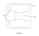
- FIG. 4illustrates an exemplary magnetic coupler
- FIG. 5( a )illustrates an element of an exemplary screen.
- FIG. 5( b )illustrates another element of an exemplary screen.
- the insertion of layers of elements illustrated in 5 ( a ) between the layers depicted in 5 ( b )may comprise an exemplary laminate structure for an exemplary screen.
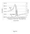
- FIG. 6( a )illustrates exemplary flux paths, including the reluctance paths and leakage inductances for an exemplary magnetic coupler with a screen.
- FIG. 6( b )illustrates an exemplary magnetic circuit for the magnetic coupler illustrated in FIG. 6( a ).
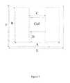
- FIG. 7illustrates an exemplary magnetic coupler with exemplary design parameters.
- FIG. 8is an illustrative graph of the coupling coefficient (y-axis) against a coil width to distance ratio (x-axis).
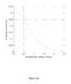
- FIG. 9is an illustrative graph of coupling coefficients for a circular pad and an exemplary new pad (y-axis) against horizontal misalignment of the transmitter and receiver (x-axis).
- FIG. 10is an illustrative graph of the coupling coefficient (y-axis) against the misalignment distance (x-axis).
- FIG. 11is an illustrative graph of the coupling coefficient (y-axis) against the length of a bottom screen (x-axis).
- FIG. 12is an illustrative graph of the coupling coefficient (y-axis) against the length of a top screen (x-axis).
- FIG. 13illustrates an exemplary designed metamaterial made on PCB.
- FIG. 14illustrates the relative permeability ( ⁇ ′ and ⁇ ′′) of an exemplary metamaterial.
- FIG. 15illustrates the total permeability and the loss tangent of an exemplary metamaterial
- a circular magnetic couplermay be used.
- Budhia et al.“Design and Optimisation of Circular Magnetic Structures for Lumped Inductive Power Transfer Systems” Energy Conversion Congress and Exposition, 2009. ECCE 2009 pp. 2081-2088 IEEE, 2009.
- FIG. 2illustrates an exploded view of such a coupler and its components. These include ferrites arranged in a fanning pattern 24 , a coil former 23 that lies on top of the ferrites 24 , a coil 22 that lies inside of the coil former 23 , and a plastic cover 21 to seal the unit together.
- a nulloccurs in the coupling and thus power profile at a horizontal offset in pads of around 30-50% of the pad diameter. This null requires extra margin in a design by precise operational alignment (often completely infeasible for applications), larger pad diameters, or overrated compensating electronic circuitry.
- FIG. 3( a )A system employing such transmitting pad is illustrated in FIG. 3( a ).
- FIG. 3( a )illustrates the ferrimagnetic material guiding the flux path.
- the flux path of this pickupcan be classified into different reluctance paths corresponding to their mutual and leakage inductances as R M , R L1 , and R L2 .
- An approximate magnetic circuit for this particular padis shown in 3 ( b ).
- the coupling coefficientmay be expressed as:
- NN 2 R M
- L L ⁇ ⁇ 1N 2 R L ⁇ ⁇ 3 ⁇ ⁇ R L ⁇ ⁇ 2 ( Formula ⁇ ⁇ 2 )
- Nis the number of turns
- R Mis the reluctance for the mutual inductance
- R L1 and R L2are the reluctance for the leakage inductance.
- the instant disclosureprovides both apparatuses and methods for improving the coupling coefficient by adopting the concept of guiding magnetic fields via soft ferrimagnetic materials like ferrite and also blocking unwanted leakage fields using materials that behave as diamagnetic materials.
- the magnetic couplerincludes a ferrimagnetic component, a coil, and a paramagnetic screen.
- An exemplary padis illustrated in FIG. 4 and described below.
- the ferrimagnetic component 43may include any material capable of guiding a magnetic field.
- Exemplary ferrimagnetic materialsinclude, for example, ferrites, soft ferrites, and soft ferrites containing iron, nickel, zinc, and/or manganese.
- Exemplary soft ferritesinclude, but are not limited to, manganese-zinc ferrite and nickel-zinc ferrite. Variations in the structure of the ferrimagnetic materials may also be employed, for example, fully sintered, substantially sintered, powder ferrite, and nanocrystalline grown structures may be used.
- the ferrimagnetic component 43may be configured so as to generate a horizontal field and may be configured into any suitable shape capable of generating such a field and/or appropriately guiding the magnetic field. In some embodiments, the ferrimagnetic component 43 is an H-shape.
- the coil 42may be constructed from any material that can carry alternating current, for example, litz wire.
- Any suitable litz wiremay be used with suitable amps rating depending on the desired output, for example, litz wire with an amp rating of from 1 amp or more, such as 1 amp to 100 amps, 3 amps to 20 amps, or 5 amps to 15 amps may be used.
- the coilis created by wrapping the wire around a portion or the entire ferrimagnetic component.
- litz wiremay be wrapped around a portion of a ferrite component, as is illustrated in FIG. 4 .
- the coil 42may be wrapped/positioned, or substantially positioned in center area of the H, as illustrated in FIG. 4 .
- a screen 41is included in the magnetic coupler to block and/or repel unwanted leakage fields.
- the screen 41may be composed of any material or combination of material capable of blocking the leakage fields.
- diamagnetic materialsmay be used as screens or as components of screens.
- Such materialsmay include specially structured conductive materials, designs based on superconductors (see, e.g., Magnus et al., “A D.C. magnetic metamaterial,” Nat Mater 7 (4), 295-297 (2008)), metamaterials, superconductive metamaterials, actively excited circuits, and partly diamagnetic materials such as bismuth, mercury, copper and carbon, or combinations thereof.
- Suitable metamaterialsmay include in their composition PCB coils, Litz wire, and low-loss PCB dielectrics as outlined in Example 2.
- FIG. 5Another exemplary screen material is illustrated in FIG. 5 .
- a structured array of electrical conductorssuch as copper, aluminum, carbon or others in a non-conducting or semiconducting medium is depicted. The length of an individual conductor and its diameter along with the spacing between conductors are selectable parameters.
- FIG. 5( b )highly conducting split-ring resonators arranged in a periodic lattice with axes aligned in the x1-direction, and one split-ring per unit cell are shown.
- the split ringsare also constructed of electrical conductors such as copper, aluminum, carbon or others and may be braided into Litz structure or the normal bundled wire.
- the split ringsmay contain an electrically non-conducting or semiconducting medium.
- the screen 41may be configured to cover all or substantially all of the ferrimagnetic component 43 and coil 42 . Such a covering may be selectively positioned on one or both of the top or bottom of the ferrimagnetic component 43 and coil 42 .
- a single screen 41may be positioned on a single side of the ferrimagnetic component 43 and coil 42 so that the leakage is blocked on a single side but the magnetic field is permitted to flow outward. This outward flow facilitates the flow between a pair of magnetic couplers, thus permitting for a more efficient wireless power transfer.
- the structureis a laminate composite made up of varying and/or alternating metamaterials referred to as ⁇ and ⁇ .
- Material ⁇could consist of a cubic lattice of well-separated cubes, where each cube has a microstructure of highly conducting rods aligned in the x1-direction.
- Material ⁇could have highly conducting split-ring resonators arranged in a periodic lattice with axes aligned in the x1-direction, and one split-ring per unit cell. The split rings behave like polarizable magnetic dipoles, and if one is just above resonance these can have negative permeability in the x1-direction.
- FIG. 6( a )illustrates an exemplary pad with a diamagnetic screen and the flux paths associated therewith, with the screen field leakage designated by the oval pointed to by the illustrated arrow.
- FIG. 6( b )illustrates a plot of leakage and mutual inductances.
- the leakage inductancehas been reduced by 39% for a flat pickup as shown in FIG. 6( b ), and hence a higher coupling coefficient can be obtained.
- a superconductor sheetthat is 5 mm thick was used to simulate the benefits of a diamagnetic screen. Note that in FIG.
- the “no scrn leakage” plotis between 20-25 mH
- the “scrn leakage” plotis between 10-15 mH
- the “scrn mutual” and “no scrn mutual” plotsare between 0-5 mH.
- a magnetic couplerwith the ability to mutually couple over great misalignments is preferred.
- the instant padnot only adopts the concept of guiding magnetic fields via soft ferrimagnetic materials like ferrite, but also blocks unwanted leakage fields using materials that behave as diamagnetic materials (e.g. low loss metal screens.) Because the losses in an IPT system are inversely proportional to the coupling coefficient squared, improving the coupling causes significant loss reduction in the system.
- C. M. Zierhofer and E. S. Hochmair“Geometric approach for coupling enhancement of magnetically coupled coils,” IEEE Transactions on Biomedical Engineering , vol. 43, no. d 7, pp. 708-714, 1996.
- the instant magnetic couplerreduces the variation in the coupling coefficient over wide misalignment conditions by researching magnetic field shaping. This is particularly important in WPT systems.
- the well-known WPT power equationis:
- the amount of reactive power stored in the systemis largely dependent on the real power (coupling dependent) and also Q 2 of the system. Since the reactive power is proportional to the square of the coupling coefficient, any change in coupling coefficient over wide misalignment will cause the system to store squared times more Volt-Amperes (VAs), which significantly reduces system efficiency. For example, for a circular pad operating with misalignments of 46% pad radius, the VAs have to be overrated by 300% (a 100% change in coupling). Compare this to the new pad operating with a misalignment of 100% pad radius, the VA only has to be overrated by 50% (a 24% change in coupling).
- the instant method and apparatusesdecrease the variation in coupling and keep the mutual inductance relatively constant over wide misalignments. Indeed, certain arrangements of materials, as illustrated in FIG. 5 and described above, that behave diamagnetically have far superior performance in holding coupling coefficient approximately constant over misalignment conditions compared to ferrimagnetic materials alone. At least one purpose of the screen is to reduce or block the excessive leakage flux that would form due to the ferrimagnetic materials alone.
- a system of multiple magnetic couplersmay be provided. Such a system may include two or more magnetic couplers.
- the pad designs described hereinmay be applied and used in the wireless power transfer systems and methods described in U.S. Provisional Patent Application No. 61/589,599, filed Jan. 23, 2012, the entirety of which is herein incorporated by reference.
- a vehicle or other electrical devicemay be equipped with at least one receiving magnetic coupler which receives a magnetic field from at least one transmitting magnetic coupler.
- Transmitting magnetic couplersmay include, for example, a single station, such as a charging station, or intermittently be positioned along a path of travel, such as a rail, road, transportation route.
- the distance over which the vehicle is to travelis directly tied to the number of transmitting magnetic couplers needed for the system. In some embodiments, millions of transmitting magnetic couplers would be necessary. In any case, the transmitting magnetic coupler is tied to a power source. The transmitting magnetic coupler emits a magnetic field which is picked up by a receiving magnetic coupler.
- An exemplary magnetic coupleris designed and compared with a circular pad, as described above.
- the parametersare illustrated and listed in FIG. 7 and the below table.
- the pickup lengthis twice the distance or air gap. It can be seen from FIG. 8 that the optimal coupling is achieved when the coil length is nearly two times the distance or the length of ferrite of the flat pickup. However, the optimal is about 80% of the pickup length rather than the full length.
- FIG. 10illustrates that the coupling coefficient changes slowly as the horizontal misalignment is increased.
- Betais defined as the normalized distance of the misalignment over the whole pad length.
- a top-side screenwas also added to the simulation and the results are shown in FIG. 12 .
- the bottom screenis set to 80% of the pickup length. It can be seen that the coupling continuously decreases as the dimensions of the top screen are increased.
- the mutual inductancecontinuously decreases because there is less area or path to allow the flux to link the two coils, hence the reluctance of the mutual flux link increases.
- the self-inductancecontinuously decreases as well as leakage flux is also reduced. However, the rate of decrease for the mutual increase is always greater than for leakage hence placing a top screen actually degrades the system performance.
- Metamaterialsmay be made with a resonant coil/ring structure on PCB's. At high frequencies, the ring's inductance may be made to resonate with its own parasitic capacitance which will be at the resonant frequency. At lower frequencies, this result may be more difficult to achieve; however, the metamaterials may be made by adding an external resonant capacitor with an inductive coil to form this resonant structure.
- FIG. 13illustrates an exemplary PCB milled metamaterial including a pcb 1301 , a conductive coil 1302 , and a capacitor 1303 connected to both ends of the coil by connectors 1304 .
- the coil inductanceis 13 uH
- capacitanceis 528 nF
- fs60 kHz.
- impedance and phase angle measurementswere made using a precision LCR meter (E4950).
- the primary excitation inductor coilwas turned into a pure resistor and a poor capacitor.
- R coil +jX coilZ cos( ⁇ )+ jZ sin( ⁇ ) (Formula 5)
- the difference between the reactance and relative permeabilitiesmay be calculated by:
- ⁇ ′L meta + L coil ( L meta + L coil ) @ 200 ⁇ ⁇ Hz ( Formula ⁇ ⁇ 7 )
Landscapes
- Engineering & Computer Science (AREA)
- Power Engineering (AREA)
- Coils Or Transformers For Communication (AREA)
Abstract
Description
Where k is the coupling coefficient, M is the mutual inductance and LL1is the primary leakage inductance. From conventional definition, the inductances of the transformer are given by:
where N is the number of turns, RMis the reluctance for the mutual inductance, and RL1and RL2are the reluctance for the leakage inductance. Substituting
where ω is the operating angular frequency, I1is primary track current, I2is the secondary inductor current, and Q2is the quality factor of the parallel resonant tank on the secondary. J. T. Boys, G. A. Covic and A. W. Green, “Stability and control of inductively coupled power transfer systems,”IEE Proceedings—Electric Power Applications, vol. 147, no. 1, pp. 37-43, 2000. This equation depicts the maximum real power that can be transferred in a WPT system without a power decoupling controller. The amount of reactive power stored in the system is largely dependent on the real power (coupling dependent) and also Q2of the system. Since the reactive power is proportional to the square of the coupling coefficient, any change in coupling coefficient over wide misalignment will cause the system to store squared times more Volt-Amperes (VAs), which significantly reduces system efficiency. For example, for a circular pad operating with misalignments of 46% pad radius, the VAs have to be overrated by 300% (a 100% change in coupling). Compare this to the new pad operating with a misalignment of 100% pad radius, the VA only has to be overrated by 50% (a 24% change in coupling).
| All dimensions in mm |
| A | 1000 pad length | |
| B | 800 pad width | |
| C | 600 coil length | |
| D | 150 gap width | |
| E | 2000 screen length | |
| F | 1800 screen width |
| Ferrite thickness: 20 |
| Coil Thickness: 20 |
| No. of Turns: 3 |
| I1 | 100 A at 100 kHz | |
As indicated in the table, the number of turns for the pad is 3. These turns are evenly distributed over the middle section of the H-shaped pad. However, the middle section is very long for 3 radial turn of wires; as such, a practical equivalent of such turns could employ multi-filiar winding where many turns would be connected in parallel to simulate the 1 complete turn. In this case, a hexa-filiar wound coil may be used with a total winding of 18 turns, but is electrically equivalent to 3.
Rcoil+jXcoil=Zcos(θ)+jZsin(θ) (Formula 5)
Claims (10)
Priority Applications (1)
| Application Number | Priority Date | Filing Date | Title |
|---|---|---|---|
| US13/648,201US9240270B2 (en) | 2011-10-07 | 2012-10-09 | Wireless power transfer magnetic couplers |
Applications Claiming Priority (2)
| Application Number | Priority Date | Filing Date | Title |
|---|---|---|---|
| US201161544957P | 2011-10-07 | 2011-10-07 | |
| US13/648,201US9240270B2 (en) | 2011-10-07 | 2012-10-09 | Wireless power transfer magnetic couplers |
Publications (2)
| Publication Number | Publication Date |
|---|---|
| US20130088090A1 US20130088090A1 (en) | 2013-04-11 |
| US9240270B2true US9240270B2 (en) | 2016-01-19 |
Family
ID=48041620
Family Applications (1)
| Application Number | Title | Priority Date | Filing Date |
|---|---|---|---|
| US13/648,201Expired - Fee RelatedUS9240270B2 (en) | 2011-10-07 | 2012-10-09 | Wireless power transfer magnetic couplers |
Country Status (1)
| Country | Link |
|---|---|
| US (1) | US9240270B2 (en) |
Cited By (6)
| Publication number | Priority date | Publication date | Assignee | Title |
|---|---|---|---|---|
| US20150255990A1 (en)* | 2012-11-15 | 2015-09-10 | The Chugoku Electric Power Co., Inc. | Non-contact power supply system and control method for non-contact power supply system |
| US9460846B2 (en) | 2014-06-20 | 2016-10-04 | Apple Inc. | Methods for forming shield materials onto inductive coils |
| US9852844B2 (en) | 2014-03-24 | 2017-12-26 | Apple Inc. | Magnetic shielding in inductive power transfer |
| US10327326B2 (en) | 2017-08-17 | 2019-06-18 | Apple Inc. | Electronic device with encapsulated circuit assembly having an integrated metal layer |
| US10699842B2 (en) | 2014-09-02 | 2020-06-30 | Apple Inc. | Magnetically doped adhesive for enhancing magnetic coupling |
| US11394241B2 (en)* | 2019-08-28 | 2022-07-19 | Delta Electronics (Thailand) Public Co., Ltd. | Resonating inductor for wireless power transfer |
Families Citing this family (204)
| Publication number | Priority date | Publication date | Assignee | Title |
|---|---|---|---|---|
| US9553485B2 (en)* | 2011-10-13 | 2017-01-24 | Integrated Device Technology, Inc. | Apparatus, system, and method for detecting a foreign object in an inductive wireless power transfer system based on input power |
| US9124125B2 (en) | 2013-05-10 | 2015-09-01 | Energous Corporation | Wireless power transmission with selective range |
| US10038337B1 (en) | 2013-09-16 | 2018-07-31 | Energous Corporation | Wireless power supply for rescue devices |
| US9900057B2 (en) | 2012-07-06 | 2018-02-20 | Energous Corporation | Systems and methods for assigning groups of antenas of a wireless power transmitter to different wireless power receivers, and determining effective phases to use for wirelessly transmitting power using the assigned groups of antennas |
| US9871398B1 (en) | 2013-07-01 | 2018-01-16 | Energous Corporation | Hybrid charging method for wireless power transmission based on pocket-forming |
| US10218227B2 (en) | 2014-05-07 | 2019-02-26 | Energous Corporation | Compact PIFA antenna |
| US10224982B1 (en) | 2013-07-11 | 2019-03-05 | Energous Corporation | Wireless power transmitters for transmitting wireless power and tracking whether wireless power receivers are within authorized locations |
| US9867062B1 (en) | 2014-07-21 | 2018-01-09 | Energous Corporation | System and methods for using a remote server to authorize a receiving device that has requested wireless power and to determine whether another receiving device should request wireless power in a wireless power transmission system |
| US10199835B2 (en) | 2015-12-29 | 2019-02-05 | Energous Corporation | Radar motion detection using stepped frequency in wireless power transmission system |
| US9893555B1 (en) | 2013-10-10 | 2018-02-13 | Energous Corporation | Wireless charging of tools using a toolbox transmitter |
| US9876648B2 (en) | 2014-08-21 | 2018-01-23 | Energous Corporation | System and method to control a wireless power transmission system by configuration of wireless power transmission control parameters |
| US9853692B1 (en) | 2014-05-23 | 2017-12-26 | Energous Corporation | Systems and methods for wireless power transmission |
| US10050462B1 (en) | 2013-08-06 | 2018-08-14 | Energous Corporation | Social power sharing for mobile devices based on pocket-forming |
| US10965164B2 (en) | 2012-07-06 | 2021-03-30 | Energous Corporation | Systems and methods of wirelessly delivering power to a receiver device |
| US9787103B1 (en) | 2013-08-06 | 2017-10-10 | Energous Corporation | Systems and methods for wirelessly delivering power to electronic devices that are unable to communicate with a transmitter |
| US10090886B1 (en) | 2014-07-14 | 2018-10-02 | Energous Corporation | System and method for enabling automatic charging schedules in a wireless power network to one or more devices |
| US11502551B2 (en) | 2012-07-06 | 2022-11-15 | Energous Corporation | Wirelessly charging multiple wireless-power receivers using different subsets of an antenna array to focus energy at different locations |
| US10193396B1 (en) | 2014-05-07 | 2019-01-29 | Energous Corporation | Cluster management of transmitters in a wireless power transmission system |
| US10211674B1 (en) | 2013-06-12 | 2019-02-19 | Energous Corporation | Wireless charging using selected reflectors |
| US9887584B1 (en) | 2014-08-21 | 2018-02-06 | Energous Corporation | Systems and methods for a configuration web service to provide configuration of a wireless power transmitter within a wireless power transmission system |
| US9793758B2 (en) | 2014-05-23 | 2017-10-17 | Energous Corporation | Enhanced transmitter using frequency control for wireless power transmission |
| US10063064B1 (en) | 2014-05-23 | 2018-08-28 | Energous Corporation | System and method for generating a power receiver identifier in a wireless power network |
| US10008889B2 (en) | 2014-08-21 | 2018-06-26 | Energous Corporation | Method for automatically testing the operational status of a wireless power receiver in a wireless power transmission system |
| US9882427B2 (en) | 2013-05-10 | 2018-01-30 | Energous Corporation | Wireless power delivery using a base station to control operations of a plurality of wireless power transmitters |
| US9954374B1 (en) | 2014-05-23 | 2018-04-24 | Energous Corporation | System and method for self-system analysis for detecting a fault in a wireless power transmission Network |
| US9838083B2 (en) | 2014-07-21 | 2017-12-05 | Energous Corporation | Systems and methods for communication with remote management systems |
| US10291055B1 (en) | 2014-12-29 | 2019-05-14 | Energous Corporation | Systems and methods for controlling far-field wireless power transmission based on battery power levels of a receiving device |
| US9893768B2 (en) | 2012-07-06 | 2018-02-13 | Energous Corporation | Methodology for multiple pocket-forming |
| US10256657B2 (en) | 2015-12-24 | 2019-04-09 | Energous Corporation | Antenna having coaxial structure for near field wireless power charging |
| US9843213B2 (en) | 2013-08-06 | 2017-12-12 | Energous Corporation | Social power sharing for mobile devices based on pocket-forming |
| US9859797B1 (en) | 2014-05-07 | 2018-01-02 | Energous Corporation | Synchronous rectifier design for wireless power receiver |
| US10063105B2 (en) | 2013-07-11 | 2018-08-28 | Energous Corporation | Proximity transmitters for wireless power charging systems |
| US10263432B1 (en) | 2013-06-25 | 2019-04-16 | Energous Corporation | Multi-mode transmitter with an antenna array for delivering wireless power and providing Wi-Fi access |
| US9991741B1 (en) | 2014-07-14 | 2018-06-05 | Energous Corporation | System for tracking and reporting status and usage information in a wireless power management system |
| US9143000B2 (en) | 2012-07-06 | 2015-09-22 | Energous Corporation | Portable wireless charging pad |
| US9973021B2 (en) | 2012-07-06 | 2018-05-15 | Energous Corporation | Receivers for wireless power transmission |
| US20140008993A1 (en) | 2012-07-06 | 2014-01-09 | DvineWave Inc. | Methodology for pocket-forming |
| US9876379B1 (en) | 2013-07-11 | 2018-01-23 | Energous Corporation | Wireless charging and powering of electronic devices in a vehicle |
| US9843201B1 (en) | 2012-07-06 | 2017-12-12 | Energous Corporation | Wireless power transmitter that selects antenna sets for transmitting wireless power to a receiver based on location of the receiver, and methods of use thereof |
| US9831718B2 (en) | 2013-07-25 | 2017-11-28 | Energous Corporation | TV with integrated wireless power transmitter |
| US10992187B2 (en) | 2012-07-06 | 2021-04-27 | Energous Corporation | System and methods of using electromagnetic waves to wirelessly deliver power to electronic devices |
| US10199849B1 (en) | 2014-08-21 | 2019-02-05 | Energous Corporation | Method for automatically testing the operational status of a wireless power receiver in a wireless power transmission system |
| US9824815B2 (en) | 2013-05-10 | 2017-11-21 | Energous Corporation | Wireless charging and powering of healthcare gadgets and sensors |
| US9912199B2 (en) | 2012-07-06 | 2018-03-06 | Energous Corporation | Receivers for wireless power transmission |
| US20150326070A1 (en) | 2014-05-07 | 2015-11-12 | Energous Corporation | Methods and Systems for Maximum Power Point Transfer in Receivers |
| US10312715B2 (en) | 2015-09-16 | 2019-06-04 | Energous Corporation | Systems and methods for wireless power charging |
| US9923386B1 (en) | 2012-07-06 | 2018-03-20 | Energous Corporation | Systems and methods for wireless power transmission by modifying a number of antenna elements used to transmit power waves to a receiver |
| US9847679B2 (en) | 2014-05-07 | 2017-12-19 | Energous Corporation | System and method for controlling communication between wireless power transmitter managers |
| US9899873B2 (en) | 2014-05-23 | 2018-02-20 | Energous Corporation | System and method for generating a power receiver identifier in a wireless power network |
| US9882430B1 (en) | 2014-05-07 | 2018-01-30 | Energous Corporation | Cluster management of transmitters in a wireless power transmission system |
| US10230266B1 (en) | 2014-02-06 | 2019-03-12 | Energous Corporation | Wireless power receivers that communicate status data indicating wireless power transmission effectiveness with a transmitter using a built-in communications component of a mobile device, and methods of use thereof |
| US10224758B2 (en) | 2013-05-10 | 2019-03-05 | Energous Corporation | Wireless powering of electronic devices with selective delivery range |
| US9438045B1 (en) | 2013-05-10 | 2016-09-06 | Energous Corporation | Methods and systems for maximum power point transfer in receivers |
| US10223717B1 (en) | 2014-05-23 | 2019-03-05 | Energous Corporation | Systems and methods for payment-based authorization of wireless power transmission service |
| US10128699B2 (en) | 2014-07-14 | 2018-11-13 | Energous Corporation | Systems and methods of providing wireless power using receiver device sensor inputs |
| US10211680B2 (en) | 2013-07-19 | 2019-02-19 | Energous Corporation | Method for 3 dimensional pocket-forming |
| US10141791B2 (en) | 2014-05-07 | 2018-11-27 | Energous Corporation | Systems and methods for controlling communications during wireless transmission of power using application programming interfaces |
| US9847677B1 (en) | 2013-10-10 | 2017-12-19 | Energous Corporation | Wireless charging and powering of healthcare gadgets and sensors |
| US9887739B2 (en) | 2012-07-06 | 2018-02-06 | Energous Corporation | Systems and methods for wireless power transmission by comparing voltage levels associated with power waves transmitted by antennas of a plurality of antennas of a transmitter to determine appropriate phase adjustments for the power waves |
| US10124754B1 (en) | 2013-07-19 | 2018-11-13 | Energous Corporation | Wireless charging and powering of electronic sensors in a vehicle |
| US9893554B2 (en) | 2014-07-14 | 2018-02-13 | Energous Corporation | System and method for providing health safety in a wireless power transmission system |
| US9948135B2 (en) | 2015-09-22 | 2018-04-17 | Energous Corporation | Systems and methods for identifying sensitive objects in a wireless charging transmission field |
| US10211682B2 (en) | 2014-05-07 | 2019-02-19 | Energous Corporation | Systems and methods for controlling operation of a transmitter of a wireless power network based on user instructions received from an authenticated computing device powered or charged by a receiver of the wireless power network |
| US9941707B1 (en) | 2013-07-19 | 2018-04-10 | Energous Corporation | Home base station for multiple room coverage with multiple transmitters |
| US9906065B2 (en) | 2012-07-06 | 2018-02-27 | Energous Corporation | Systems and methods of transmitting power transmission waves based on signals received at first and second subsets of a transmitter's antenna array |
| US10090699B1 (en) | 2013-11-01 | 2018-10-02 | Energous Corporation | Wireless powered house |
| US9939864B1 (en) | 2014-08-21 | 2018-04-10 | Energous Corporation | System and method to control a wireless power transmission system by configuration of wireless power transmission control parameters |
| US10186913B2 (en) | 2012-07-06 | 2019-01-22 | Energous Corporation | System and methods for pocket-forming based on constructive and destructive interferences to power one or more wireless power receivers using a wireless power transmitter including a plurality of antennas |
| US9252628B2 (en) | 2013-05-10 | 2016-02-02 | Energous Corporation | Laptop computer as a transmitter for wireless charging |
| US10270261B2 (en) | 2015-09-16 | 2019-04-23 | Energous Corporation | Systems and methods of object detection in wireless power charging systems |
| US10063106B2 (en) | 2014-05-23 | 2018-08-28 | Energous Corporation | System and method for a self-system analysis in a wireless power transmission network |
| US10206185B2 (en) | 2013-05-10 | 2019-02-12 | Energous Corporation | System and methods for wireless power transmission to an electronic device in accordance with user-defined restrictions |
| US9859756B2 (en) | 2012-07-06 | 2018-01-02 | Energous Corporation | Transmittersand methods for adjusting wireless power transmission based on information from receivers |
| US9368020B1 (en) | 2013-05-10 | 2016-06-14 | Energous Corporation | Off-premises alert system and method for wireless power receivers in a wireless power network |
| US10075008B1 (en) | 2014-07-14 | 2018-09-11 | Energous Corporation | Systems and methods for manually adjusting when receiving electronic devices are scheduled to receive wirelessly delivered power from a wireless power transmitter in a wireless power network |
| US10141768B2 (en) | 2013-06-03 | 2018-11-27 | Energous Corporation | Systems and methods for maximizing wireless power transfer efficiency by instructing a user to change a receiver device's position |
| US9966765B1 (en) | 2013-06-25 | 2018-05-08 | Energous Corporation | Multi-mode transmitter |
| US9853458B1 (en) | 2014-05-07 | 2017-12-26 | Energous Corporation | Systems and methods for device and power receiver pairing |
| US9876394B1 (en) | 2014-05-07 | 2018-01-23 | Energous Corporation | Boost-charger-boost system for enhanced power delivery |
| US10103582B2 (en) | 2012-07-06 | 2018-10-16 | Energous Corporation | Transmitters for wireless power transmission |
| US10243414B1 (en) | 2014-05-07 | 2019-03-26 | Energous Corporation | Wearable device with wireless power and payload receiver |
| US10291066B1 (en) | 2014-05-07 | 2019-05-14 | Energous Corporation | Power transmission control systems and methods |
| US10205239B1 (en) | 2014-05-07 | 2019-02-12 | Energous Corporation | Compact PIFA antenna |
| US9941747B2 (en) | 2014-07-14 | 2018-04-10 | Energous Corporation | System and method for manually selecting and deselecting devices to charge in a wireless power network |
| US9806564B2 (en) | 2014-05-07 | 2017-10-31 | Energous Corporation | Integrated rectifier and boost converter for wireless power transmission |
| US10148097B1 (en) | 2013-11-08 | 2018-12-04 | Energous Corporation | Systems and methods for using a predetermined number of communication channels of a wireless power transmitter to communicate with different wireless power receivers |
| US10128693B2 (en) | 2014-07-14 | 2018-11-13 | Energous Corporation | System and method for providing health safety in a wireless power transmission system |
| US9859757B1 (en) | 2013-07-25 | 2018-01-02 | Energous Corporation | Antenna tile arrangements in electronic device enclosures |
| US9899861B1 (en) | 2013-10-10 | 2018-02-20 | Energous Corporation | Wireless charging methods and systems for game controllers, based on pocket-forming |
| US9825674B1 (en) | 2014-05-23 | 2017-11-21 | Energous Corporation | Enhanced transmitter that selects configurations of antenna elements for performing wireless power transmission and receiving functions |
| US10992185B2 (en) | 2012-07-06 | 2021-04-27 | Energous Corporation | Systems and methods of using electromagnetic waves to wirelessly deliver power to game controllers |
| US9812890B1 (en) | 2013-07-11 | 2017-11-07 | Energous Corporation | Portable wireless charging pad |
| US12057715B2 (en) | 2012-07-06 | 2024-08-06 | Energous Corporation | Systems and methods of wirelessly delivering power to a wireless-power receiver device in response to a change of orientation of the wireless-power receiver device |
| US10381880B2 (en) | 2014-07-21 | 2019-08-13 | Energous Corporation | Integrated antenna structure arrays for wireless power transmission |
| US9891669B2 (en) | 2014-08-21 | 2018-02-13 | Energous Corporation | Systems and methods for a configuration web service to provide configuration of a wireless power transmitter within a wireless power transmission system |
| US10439448B2 (en) | 2014-08-21 | 2019-10-08 | Energous Corporation | Systems and methods for automatically testing the communication between wireless power transmitter and wireless power receiver |
| US9941754B2 (en) | 2012-07-06 | 2018-04-10 | Energous Corporation | Wireless power transmission with selective range |
| KR101601352B1 (en)* | 2012-09-26 | 2016-03-08 | 엘지이노텍 주식회사 | Apparatus for transmitting wireless power and method for controlling power thereof |
| US9537357B2 (en) | 2013-05-10 | 2017-01-03 | Energous Corporation | Wireless sound charging methods and systems for game controllers, based on pocket-forming |
| US9819230B2 (en) | 2014-05-07 | 2017-11-14 | Energous Corporation | Enhanced receiver for wireless power transmission |
| US9866279B2 (en) | 2013-05-10 | 2018-01-09 | Energous Corporation | Systems and methods for selecting which power transmitter should deliver wireless power to a receiving device in a wireless power delivery network |
| US9538382B2 (en) | 2013-05-10 | 2017-01-03 | Energous Corporation | System and method for smart registration of wireless power receivers in a wireless power network |
| US9419443B2 (en) | 2013-05-10 | 2016-08-16 | Energous Corporation | Transducer sound arrangement for pocket-forming |
| US10103552B1 (en) | 2013-06-03 | 2018-10-16 | Energous Corporation | Protocols for authenticated wireless power transmission |
| US10003211B1 (en) | 2013-06-17 | 2018-06-19 | Energous Corporation | Battery life of portable electronic devices |
| US10021523B2 (en) | 2013-07-11 | 2018-07-10 | Energous Corporation | Proximity transmitters for wireless power charging systems |
| US9979440B1 (en) | 2013-07-25 | 2018-05-22 | Energous Corporation | Antenna tile arrangements configured to operate as one functional unit |
| KR20150089345A (en)* | 2014-01-27 | 2015-08-05 | 조선대학교산학협력단 | Wireless charger for electric cars |
| US10075017B2 (en) | 2014-02-06 | 2018-09-11 | Energous Corporation | External or internal wireless power receiver with spaced-apart antenna elements for charging or powering mobile devices using wirelessly delivered power |
| US9935482B1 (en) | 2014-02-06 | 2018-04-03 | Energous Corporation | Wireless power transmitters that transmit at determined times based on power availability and consumption at a receiving mobile device |
| US9966784B2 (en) | 2014-06-03 | 2018-05-08 | Energous Corporation | Systems and methods for extending battery life of portable electronic devices charged by sound |
| US10158257B2 (en) | 2014-05-01 | 2018-12-18 | Energous Corporation | System and methods for using sound waves to wirelessly deliver power to electronic devices |
| US10153653B1 (en) | 2014-05-07 | 2018-12-11 | Energous Corporation | Systems and methods for using application programming interfaces to control communications between a transmitter and a receiver |
| US10170917B1 (en) | 2014-05-07 | 2019-01-01 | Energous Corporation | Systems and methods for managing and controlling a wireless power network by establishing time intervals during which receivers communicate with a transmitter |
| US9973008B1 (en) | 2014-05-07 | 2018-05-15 | Energous Corporation | Wireless power receiver with boost converters directly coupled to a storage element |
| US9800172B1 (en) | 2014-05-07 | 2017-10-24 | Energous Corporation | Integrated rectifier and boost converter for boosting voltage received from wireless power transmission waves |
| US10153645B1 (en) | 2014-05-07 | 2018-12-11 | Energous Corporation | Systems and methods for designating a master power transmitter in a cluster of wireless power transmitters |
| US9876536B1 (en) | 2014-05-23 | 2018-01-23 | Energous Corporation | Systems and methods for assigning groups of antennas to transmit wireless power to different wireless power receivers |
| US10068703B1 (en) | 2014-07-21 | 2018-09-04 | Energous Corporation | Integrated miniature PIFA with artificial magnetic conductor metamaterials |
| US10116143B1 (en) | 2014-07-21 | 2018-10-30 | Energous Corporation | Integrated antenna arrays for wireless power transmission |
| US9871301B2 (en) | 2014-07-21 | 2018-01-16 | Energous Corporation | Integrated miniature PIFA with artificial magnetic conductor metamaterials |
| WO2016024868A1 (en)* | 2014-08-11 | 2016-02-18 | Auckland Uniservices Limited | Resonant frequency compensation |
| US9917477B1 (en) | 2014-08-21 | 2018-03-13 | Energous Corporation | Systems and methods for automatically testing the communication between power transmitter and wireless receiver |
| US9965009B1 (en) | 2014-08-21 | 2018-05-08 | Energous Corporation | Systems and methods for assigning a power receiver to individual power transmitters based on location of the power receiver |
| US9923406B2 (en)* | 2015-09-04 | 2018-03-20 | Qualcomm Incorporated | System and method for reducing leakage flux in wireless charging systems |
| US9889754B2 (en) | 2014-09-09 | 2018-02-13 | Qualcomm Incorporated | System and method for reducing leakage flux in wireless electric vehicle charging systems |
| CN104409818A (en)* | 2014-12-01 | 2015-03-11 | 清华大学 | Ferrite-based metamaterial for adjustable band-stop filter and application of ferrite-based metamaterial |
| US10122415B2 (en) | 2014-12-27 | 2018-11-06 | Energous Corporation | Systems and methods for assigning a set of antennas of a wireless power transmitter to a wireless power receiver based on a location of the wireless power receiver |
| US9893535B2 (en) | 2015-02-13 | 2018-02-13 | Energous Corporation | Systems and methods for determining optimal charging positions to maximize efficiency of power received from wirelessly delivered sound wave energy |
| US10523033B2 (en) | 2015-09-15 | 2019-12-31 | Energous Corporation | Receiver devices configured to determine location within a transmission field |
| US9906275B2 (en) | 2015-09-15 | 2018-02-27 | Energous Corporation | Identifying receivers in a wireless charging transmission field |
| US12283828B2 (en) | 2015-09-15 | 2025-04-22 | Energous Corporation | Receiver devices configured to determine location within a transmission field |
| US10778041B2 (en) | 2015-09-16 | 2020-09-15 | Energous Corporation | Systems and methods for generating power waves in a wireless power transmission system |
| US11710321B2 (en) | 2015-09-16 | 2023-07-25 | Energous Corporation | Systems and methods of object detection in wireless power charging systems |
| US10008875B1 (en) | 2015-09-16 | 2018-06-26 | Energous Corporation | Wireless power transmitter configured to transmit power waves to a predicted location of a moving wireless power receiver |
| US10158259B1 (en) | 2015-09-16 | 2018-12-18 | Energous Corporation | Systems and methods for identifying receivers in a transmission field by transmitting exploratory power waves towards different segments of a transmission field |
| US9893538B1 (en) | 2015-09-16 | 2018-02-13 | Energous Corporation | Systems and methods of object detection in wireless power charging systems |
| US10186893B2 (en) | 2015-09-16 | 2019-01-22 | Energous Corporation | Systems and methods for real time or near real time wireless communications between a wireless power transmitter and a wireless power receiver |
| US10211685B2 (en) | 2015-09-16 | 2019-02-19 | Energous Corporation | Systems and methods for real or near real time wireless communications between a wireless power transmitter and a wireless power receiver |
| US9941752B2 (en) | 2015-09-16 | 2018-04-10 | Energous Corporation | Systems and methods of object detection in wireless power charging systems |
| US9871387B1 (en) | 2015-09-16 | 2018-01-16 | Energous Corporation | Systems and methods of object detection using one or more video cameras in wireless power charging systems |
| US10199850B2 (en) | 2015-09-16 | 2019-02-05 | Energous Corporation | Systems and methods for wirelessly transmitting power from a transmitter to a receiver by determining refined locations of the receiver in a segmented transmission field associated with the transmitter |
| US10135295B2 (en) | 2015-09-22 | 2018-11-20 | Energous Corporation | Systems and methods for nullifying energy levels for wireless power transmission waves |
| US10033222B1 (en) | 2015-09-22 | 2018-07-24 | Energous Corporation | Systems and methods for determining and generating a waveform for wireless power transmission waves |
| US10153660B1 (en) | 2015-09-22 | 2018-12-11 | Energous Corporation | Systems and methods for preconfiguring sensor data for wireless charging systems |
| US10050470B1 (en) | 2015-09-22 | 2018-08-14 | Energous Corporation | Wireless power transmission device having antennas oriented in three dimensions |
| US10135294B1 (en) | 2015-09-22 | 2018-11-20 | Energous Corporation | Systems and methods for preconfiguring transmission devices for power wave transmissions based on location data of one or more receivers |
| US10027168B2 (en) | 2015-09-22 | 2018-07-17 | Energous Corporation | Systems and methods for generating and transmitting wireless power transmission waves using antennas having a spacing that is selected by the transmitter |
| US10020678B1 (en) | 2015-09-22 | 2018-07-10 | Energous Corporation | Systems and methods for selecting antennas to generate and transmit power transmission waves |
| US10128686B1 (en) | 2015-09-22 | 2018-11-13 | Energous Corporation | Systems and methods for identifying receiver locations using sensor technologies |
| US10333332B1 (en) | 2015-10-13 | 2019-06-25 | Energous Corporation | Cross-polarized dipole antenna |
| US10734717B2 (en) | 2015-10-13 | 2020-08-04 | Energous Corporation | 3D ceramic mold antenna |
| US9853485B2 (en) | 2015-10-28 | 2017-12-26 | Energous Corporation | Antenna for wireless charging systems |
| US9899744B1 (en) | 2015-10-28 | 2018-02-20 | Energous Corporation | Antenna for wireless charging systems |
| US10135112B1 (en) | 2015-11-02 | 2018-11-20 | Energous Corporation | 3D antenna mount |
| US10027180B1 (en) | 2015-11-02 | 2018-07-17 | Energous Corporation | 3D triple linear antenna that acts as heat sink |
| US10063108B1 (en) | 2015-11-02 | 2018-08-28 | Energous Corporation | Stamped three-dimensional antenna |
| US10079515B2 (en) | 2016-12-12 | 2018-09-18 | Energous Corporation | Near-field RF charging pad with multi-band antenna element with adaptive loading to efficiently charge an electronic device at any position on the pad |
| US10256677B2 (en) | 2016-12-12 | 2019-04-09 | Energous Corporation | Near-field RF charging pad with adaptive loading to efficiently charge an electronic device at any position on the pad |
| US10038332B1 (en) | 2015-12-24 | 2018-07-31 | Energous Corporation | Systems and methods of wireless power charging through multiple receiving devices |
| US10320446B2 (en) | 2015-12-24 | 2019-06-11 | Energous Corporation | Miniaturized highly-efficient designs for near-field power transfer system |
| US10116162B2 (en) | 2015-12-24 | 2018-10-30 | Energous Corporation | Near field transmitters with harmonic filters for wireless power charging |
| US11863001B2 (en) | 2015-12-24 | 2024-01-02 | Energous Corporation | Near-field antenna for wireless power transmission with antenna elements that follow meandering patterns |
| US10027159B2 (en) | 2015-12-24 | 2018-07-17 | Energous Corporation | Antenna for transmitting wireless power signals |
| US10008886B2 (en) | 2015-12-29 | 2018-06-26 | Energous Corporation | Modular antennas with heat sinks in wireless power transmission systems |
| US10923954B2 (en) | 2016-11-03 | 2021-02-16 | Energous Corporation | Wireless power receiver with a synchronous rectifier |
| KR102185600B1 (en) | 2016-12-12 | 2020-12-03 | 에너저스 코포레이션 | A method of selectively activating antenna zones of a near field charging pad to maximize transmitted wireless power |
| US10680319B2 (en) | 2017-01-06 | 2020-06-09 | Energous Corporation | Devices and methods for reducing mutual coupling effects in wireless power transmission systems |
| US10389161B2 (en) | 2017-03-15 | 2019-08-20 | Energous Corporation | Surface mount dielectric antennas for wireless power transmitters |
| US10439442B2 (en) | 2017-01-24 | 2019-10-08 | Energous Corporation | Microstrip antennas for wireless power transmitters |
| US11011942B2 (en) | 2017-03-30 | 2021-05-18 | Energous Corporation | Flat antennas having two or more resonant frequencies for use in wireless power transmission systems |
| WO2018215085A1 (en) | 2017-05-02 | 2018-11-29 | Magment Ug (Haftungsbeschränkt) | Method for reducing stray fields in inductive energy transmission |
| US10511097B2 (en) | 2017-05-12 | 2019-12-17 | Energous Corporation | Near-field antennas for accumulating energy at a near-field distance with minimal far-field gain |
| US12074460B2 (en) | 2017-05-16 | 2024-08-27 | Wireless Electrical Grid Lan, Wigl Inc. | Rechargeable wireless power bank and method of using |
| US11462949B2 (en) | 2017-05-16 | 2022-10-04 | Wireless electrical Grid LAN, WiGL Inc | Wireless charging method and system |
| US12074452B2 (en) | 2017-05-16 | 2024-08-27 | Wireless Electrical Grid Lan, Wigl Inc. | Networked wireless charging system |
| US12159745B2 (en)* | 2017-05-30 | 2024-12-03 | InductEV, Inc. | Wireless power transfer thin profile coil assembly |
| US10848853B2 (en) | 2017-06-23 | 2020-11-24 | Energous Corporation | Systems, methods, and devices for utilizing a wire of a sound-producing device as an antenna for receipt of wirelessly delivered power |
| US10122219B1 (en) | 2017-10-10 | 2018-11-06 | Energous Corporation | Systems, methods, and devices for using a battery as a antenna for receiving wirelessly delivered power from radio frequency power waves |
| US11342798B2 (en) | 2017-10-30 | 2022-05-24 | Energous Corporation | Systems and methods for managing coexistence of wireless-power signals and data signals operating in a same frequency band |
| CN111742464A (en) | 2017-12-22 | 2020-10-02 | 无线先进车辆电气化有限公司 | Wireless Power Transfer Pad with Multiple Windings |
| US11462943B2 (en) | 2018-01-30 | 2022-10-04 | Wireless Advanced Vehicle Electrification, Llc | DC link charging of capacitor in a wireless power transfer pad |
| US10615647B2 (en) | 2018-02-02 | 2020-04-07 | Energous Corporation | Systems and methods for detecting wireless power receivers and other objects at a near-field charging pad |
| US11437854B2 (en) | 2018-02-12 | 2022-09-06 | Wireless Advanced Vehicle Electrification, Llc | Variable wireless power transfer system |
| US11159057B2 (en) | 2018-03-14 | 2021-10-26 | Energous Corporation | Loop antennas with selectively-activated feeds to control propagation patterns of wireless power signals |
| US11515732B2 (en) | 2018-06-25 | 2022-11-29 | Energous Corporation | Power wave transmission techniques to focus wirelessly delivered power at a receiving device |
| US11437735B2 (en) | 2018-11-14 | 2022-09-06 | Energous Corporation | Systems for receiving electromagnetic energy using antennas that are minimally affected by the presence of the human body |
| CN109704744B (en)* | 2019-01-23 | 2021-08-10 | 东莞顺络电子有限公司 | RX end ferrite material and magnetic sheet for wireless charging and manufacturing method thereof |
| US11539243B2 (en) | 2019-01-28 | 2022-12-27 | Energous Corporation | Systems and methods for miniaturized antenna for wireless power transmissions |
| EP3921945A1 (en) | 2019-02-06 | 2021-12-15 | Energous Corporation | Systems and methods of estimating optimal phases to use for individual antennas in an antenna array |
| US12155231B2 (en) | 2019-04-09 | 2024-11-26 | Energous Corporation | Asymmetric spiral antennas for wireless power transmission and reception |
| US11521792B2 (en)* | 2019-09-16 | 2022-12-06 | Utah State University | Wireless power transfer with active field cancellation using multiple magnetic flux sinks |
| WO2021055899A1 (en) | 2019-09-20 | 2021-03-25 | Energous Corporation | Systems and methods of protecting wireless power receivers using multiple rectifiers and establishing in-band communications using multiple rectifiers |
| CN114731061A (en) | 2019-09-20 | 2022-07-08 | 艾诺格思公司 | Classifying and detecting foreign objects using a power amplifier controller integrated circuit in a wireless power transmission system |
| US11381118B2 (en) | 2019-09-20 | 2022-07-05 | Energous Corporation | Systems and methods for machine learning based foreign object detection for wireless power transmission |
| WO2021055901A1 (en) | 2019-09-20 | 2021-03-25 | Energous Corporation | Asymmetric spiral antennas with parasitic elements for wireless power transmission |
| WO2021055898A1 (en) | 2019-09-20 | 2021-03-25 | Energous Corporation | Systems and methods for machine learning based foreign object detection for wireless power transmission |
| US11355966B2 (en) | 2019-12-13 | 2022-06-07 | Energous Corporation | Charging pad with guiding contours to align an electronic device on the charging pad and efficiently transfer near-field radio-frequency energy to the electronic device |
| US10985617B1 (en) | 2019-12-31 | 2021-04-20 | Energous Corporation | System for wirelessly transmitting energy at a near-field distance without using beam-forming control |
| US11799324B2 (en) | 2020-04-13 | 2023-10-24 | Energous Corporation | Wireless-power transmitting device for creating a uniform near-field charging area |
| US11469629B2 (en) | 2020-08-12 | 2022-10-11 | Energous Corporation | Systems and methods for secure wireless transmission of power using unidirectional communication signals from a wireless-power-receiving device |
| US12306285B2 (en) | 2020-12-01 | 2025-05-20 | Energous Corporation | Systems and methods for using one or more sensors to detect and classify objects in a keep-out zone of a wireless-power transmission field, and antennas with integrated sensor arrangements |
| US11916398B2 (en) | 2021-12-29 | 2024-02-27 | Energous Corporation | Small form-factor devices with integrated and modular harvesting receivers, and shelving-mounted wireless-power transmitters for use therewith |
| US12142939B2 (en) | 2022-05-13 | 2024-11-12 | Energous Corporation | Integrated wireless-power-transmission platform designed to operate in multiple bands, and multi-band antennas for use therewith |
Citations (26)
| Publication number | Priority date | Publication date | Assignee | Title |
|---|---|---|---|---|
| US4661897A (en) | 1985-01-23 | 1987-04-28 | Allied Corporation | Phase modulated, resonant power converting high frequency link inverter/converter |
| US4908347A (en)* | 1985-11-20 | 1990-03-13 | Allied-Signal Inc. | Dynamoelectric machine with diamagnetic flux shield |
| FR2738417A1 (en) | 1995-08-30 | 1997-03-07 | Gaia Converter | CONTINUOUSLY SWITCHED VOLTAGE CONVERTER |
| US6317338B1 (en) | 1997-05-06 | 2001-11-13 | Auckland Uniservices Limited | Power supply for an electroluminescent display |
| US6366051B1 (en) | 2000-05-08 | 2002-04-02 | Lear Corporation | System for automatically charging the battery of a remote transmitter for use in a vehicle security system |
| US6448745B1 (en) | 2002-01-08 | 2002-09-10 | Dialog Semiconductor Gmbh | Converter with inductor and digital controlled timing |
| US20060181906A1 (en) | 2005-02-14 | 2006-08-17 | Issa Batarseh | Alternated duty cycle control method for half-bridge DC-DC converter |
| EP1717940A2 (en) | 2005-04-04 | 2006-11-02 | THOMSON Licensing | DC voltage converter with soft switching |
| US7148669B2 (en) | 2004-02-02 | 2006-12-12 | The Regents Of The University Of Colorado, A Body Corporate | Predictive digital current controllers for switching power converters |
| TW200810315A (en) | 2006-08-14 | 2008-02-16 | Ching-Tsai Pan | Power circuit component parameters design method for compensating the loosely coupled inductive power transfer system |
| US20080203992A1 (en) | 2007-02-23 | 2008-08-28 | Jaber Abu Qahouq | Adaptive controller with mode tracking and parametric estimation for digital power converters |
| US20090174263A1 (en) | 2008-01-07 | 2009-07-09 | Access Business Group International Llc | Inductive power supply with duty cycle control |
| US20090267582A1 (en) | 2008-04-29 | 2009-10-29 | Exar Corporation | Self-tuning digital current estimator for low-power switching converters |
| US20100109604A1 (en) | 2007-05-10 | 2010-05-06 | John Talbot Boys | Multi power sourced electric vehicle |
| US20100134215A1 (en) | 2008-12-01 | 2010-06-03 | Toyota Motor Engineering & Manufacturing North America, Inc. | Thin film based split resonator tunable metamaterial |
| US20100231340A1 (en)* | 2008-09-27 | 2010-09-16 | Ron Fiorello | Wireless energy transfer resonator enclosures |
| RU2412514C2 (en) | 2006-09-29 | 2011-02-20 | Тойота Дзидося Кабусики Кайся | Power supply device and transport vehicle with power supply device |
| US20110049978A1 (en) | 2008-10-02 | 2011-03-03 | Toyota Jidosha Kabushiki Kaisha | Self-resonant coil, non-contact electric power transfer device and vehicle |
| US20110163542A1 (en) | 2006-10-25 | 2011-07-07 | Laszlo Farkas | High power wireless resonant energy transfer system |
| US20110181240A1 (en) | 2010-01-05 | 2011-07-28 | Access Business Group International Llc | Inductive charging system for electric vehicle |
| US20110304216A1 (en) | 2010-06-10 | 2011-12-15 | Access Business Group International Llc | Coil configurations for inductive power transer |
| WO2012001291A2 (en) | 2010-07-01 | 2012-01-05 | Renault S.A.S. | Contactless charging of a motor vehicle battery |
| WO2012007942A2 (en) | 2010-07-12 | 2012-01-19 | Powermat Ltd. | Power management system and method for an inductive power transfer system |
| US20120049620A1 (en) | 2009-05-11 | 2012-03-01 | Koninklijke Philips Electronics N.V. | Inductive power transfer for wireless sensor systems inside a tyre |
| US20120112552A1 (en)* | 2010-09-26 | 2012-05-10 | Access Business Group International Llc | Selectively controllable electromagnetic shielding |
| US20130049484A1 (en) | 2010-04-30 | 2013-02-28 | Powermat Technologies Ltd. | System and method for transferring power inductively over an extended region |
- 2012
- 2012-10-09USUS13/648,201patent/US9240270B2/ennot_activeExpired - Fee Related
Patent Citations (28)
| Publication number | Priority date | Publication date | Assignee | Title |
|---|---|---|---|---|
| US4661897A (en) | 1985-01-23 | 1987-04-28 | Allied Corporation | Phase modulated, resonant power converting high frequency link inverter/converter |
| US4908347A (en)* | 1985-11-20 | 1990-03-13 | Allied-Signal Inc. | Dynamoelectric machine with diamagnetic flux shield |
| FR2738417A1 (en) | 1995-08-30 | 1997-03-07 | Gaia Converter | CONTINUOUSLY SWITCHED VOLTAGE CONVERTER |
| US6317338B1 (en) | 1997-05-06 | 2001-11-13 | Auckland Uniservices Limited | Power supply for an electroluminescent display |
| US6366051B1 (en) | 2000-05-08 | 2002-04-02 | Lear Corporation | System for automatically charging the battery of a remote transmitter for use in a vehicle security system |
| US6448745B1 (en) | 2002-01-08 | 2002-09-10 | Dialog Semiconductor Gmbh | Converter with inductor and digital controlled timing |
| US7148669B2 (en) | 2004-02-02 | 2006-12-12 | The Regents Of The University Of Colorado, A Body Corporate | Predictive digital current controllers for switching power converters |
| US20060181906A1 (en) | 2005-02-14 | 2006-08-17 | Issa Batarseh | Alternated duty cycle control method for half-bridge DC-DC converter |
| EP1717940A2 (en) | 2005-04-04 | 2006-11-02 | THOMSON Licensing | DC voltage converter with soft switching |
| TW200810315A (en) | 2006-08-14 | 2008-02-16 | Ching-Tsai Pan | Power circuit component parameters design method for compensating the loosely coupled inductive power transfer system |
| RU2412514C2 (en) | 2006-09-29 | 2011-02-20 | Тойота Дзидося Кабусики Кайся | Power supply device and transport vehicle with power supply device |
| US20110163542A1 (en) | 2006-10-25 | 2011-07-07 | Laszlo Farkas | High power wireless resonant energy transfer system |
| US20080203992A1 (en) | 2007-02-23 | 2008-08-28 | Jaber Abu Qahouq | Adaptive controller with mode tracking and parametric estimation for digital power converters |
| US7652459B2 (en) | 2007-02-23 | 2010-01-26 | Intel Corporation | Adaptive controller with mode tracking and parametric estimation for digital power converters |
| US20100109604A1 (en) | 2007-05-10 | 2010-05-06 | John Talbot Boys | Multi power sourced electric vehicle |
| US20090174263A1 (en) | 2008-01-07 | 2009-07-09 | Access Business Group International Llc | Inductive power supply with duty cycle control |
| US20090267582A1 (en) | 2008-04-29 | 2009-10-29 | Exar Corporation | Self-tuning digital current estimator for low-power switching converters |
| US8085024B2 (en) | 2008-04-29 | 2011-12-27 | Exar Corporation | Self-tuning digital current estimator for low-power switching converters |
| US20100231340A1 (en)* | 2008-09-27 | 2010-09-16 | Ron Fiorello | Wireless energy transfer resonator enclosures |
| US20110049978A1 (en) | 2008-10-02 | 2011-03-03 | Toyota Jidosha Kabushiki Kaisha | Self-resonant coil, non-contact electric power transfer device and vehicle |
| US20100134215A1 (en) | 2008-12-01 | 2010-06-03 | Toyota Motor Engineering & Manufacturing North America, Inc. | Thin film based split resonator tunable metamaterial |
| US20120049620A1 (en) | 2009-05-11 | 2012-03-01 | Koninklijke Philips Electronics N.V. | Inductive power transfer for wireless sensor systems inside a tyre |
| US20110181240A1 (en) | 2010-01-05 | 2011-07-28 | Access Business Group International Llc | Inductive charging system for electric vehicle |
| US20130049484A1 (en) | 2010-04-30 | 2013-02-28 | Powermat Technologies Ltd. | System and method for transferring power inductively over an extended region |
| US20110304216A1 (en) | 2010-06-10 | 2011-12-15 | Access Business Group International Llc | Coil configurations for inductive power transer |
| WO2012001291A2 (en) | 2010-07-01 | 2012-01-05 | Renault S.A.S. | Contactless charging of a motor vehicle battery |
| WO2012007942A2 (en) | 2010-07-12 | 2012-01-19 | Powermat Ltd. | Power management system and method for an inductive power transfer system |
| US20120112552A1 (en)* | 2010-09-26 | 2012-05-10 | Access Business Group International Llc | Selectively controllable electromagnetic shielding |
Non-Patent Citations (36)
| Title |
|---|
| Borage et al., Analysis and design of an LCL-T resonant converter as a constant-current power supply, 52 IEEE Int'l Electric Machines & Drives Conf. 1547-1554 (2005). |
| Borage et al., Analysis and design of an LCL-T resonant converter as a constant-current power supply, 52 IEEE Transactions on Industrial Electronics 1547-1554 (2005). |
| Boys et al., Controlling inrush currents in inductively coupled power systems, 7 IEEE Int'l Power Engineering Conference 1046-1051 (2005). |
| Boys et al., Single-phase unity power-factor inductive power transfer system, 2008 IEEE Power Electronics Specialists Conf. 3701-3706. |
| Boys et al., Stability and control for inductively coupled power transfer systems, 147 IEE Proc.-Electric Power Applications 37-43 (2000). |
| Brooker et al., Technology improvement pathways to cost effective vehicle electrification, 2010 SAE2010 World Cong. 1-18 (Feb. 1, 2010). |
| Budhia et al., A new IPT magnetic coupler for electric vehicle charging systems 36 IEEE Industrial Electronics and Applications 2487-2492 (Nov. 7-10, 2010). |
| Budhia et al., A new IPT magnetic coupler for electric vehicle charging systems, 36 IEEE Industrial Electronics Conf. 2487-2492 (Nov. 10-17, 2010). |
| Budhia et al., Design and Optimisation of Circular Magnetic Structures for Lumped Inductive Power Transfer Systems, 2009 Energy Conversion Cong. and Expo 2081-2088 (Sep. 20-24, 2009). |
| Budhia et al., Development and evaluation of single sided flux couplers for contactless electric vehicle charging, 2011 IEEE Energy Conversion Cong. and Expo 613-621 (Sep. 17-22, 2011). |
| Chigira et al., Small-Size Light-Weight Transformer with New Core Structure for Contactless Electric Vehicle Power Transfer System, 2011 IEEE Energy Conversion Cong. and Expo 260-266 (Sep. 17-22, 2011). |
| Ciappa et al., Lifetime prediction of IGBT modules for traction applications, 38 IEEE Reliability Physics Symp. 210-216 (2000). |
| Covic et al., A Three-Phase Inductive Power Transfer System for Roadway-Powered Vehicles, 54:6 IEEE Transactions on Industrial Applications 3370-3378 (2007). |
| Covic et al., Self tuning pick-ups for inductive power transfer, 2008 IEEE Power Electronics Specialists Conf. 3489-3494. |
| Elliott et al., Multiphase Pickups for Large Lateral Tolerance Contactless Power-Transfer Systems, 57 IEEE Transactions on Industrial Electronics 1590-1598 (May 2010). |
| Huang et al., LCL pick-up circulating current controller for inductive power transfer systems, 2010 IEEE Energy Conversion Cong. and Exposition (ECCE) 640-646 (Sep. 12-16, 2010). |
| Jin et al., Characterization of novel Inductive Power Transfer Systems for On-Line Electric Vehicles, 26 IEEE Applied Power Electronics Conference and Expo 1975-1979 (Mar. 6-11, 2011). |
| Joung et al., An energy transmission system for an artificial heart using leakage inductance compensation of transcutaneous transformer, 13 IEEE Transactions on Power Electronics 1013-1022 (1998). |
| Keeling et al., A Unity-Power-Factor IPT Pickup for High-Power Applications, 57 IEEE Transactions on Industrial Electronics 744-751 (Feb. 2010). |
| Magnus et al., "A d.c. magnetic metamaterial", vol. 7, Nature Materials by Nature Publishing Group, pp. 295-297 (Apr. 2008).* |
| Magnus et al., A d.c. magnetic metamaterial, 7:4 Nat. Mater. 295-297 (2008). |
| Milton et al., Realizability of metamaterials with prescribed electric permittivity and magnetic permeability tensors, 12 New Journal of Physics (Mar. 2010). |
| Musavi et al., A High-Performance Single-Phase Bridgeless Interleaved PFC Converter for Plug-in Hybrid Electric Vehicle Battery Chargers, 47 IEEE Transactions on Industry Applications 1833-1843 (Jul.-Aug. 2011). |
| Nagatsuka et al., Compact contactless power transfer system for electric vehicles, 2010 Int'l Power Electronics Conf. 807-813 (Jun. 21-24, 2010). |
| Nakao et al., Ferrite core couplers for inductive chargers, 2 Power Conversion Conf. 850-854 (2002). |
| Sasaki et al., Thermal and Structural Simulation Techniques for Estimating Fatigue of an IGBT Module, 20 Power Semiconductor Devices and IC's 181-184 (2008). |
| Schurig, D. et al., "Electric-field-coupled resonators for negative permittivity metamaterials," Appl. Phys. Lett. 88, 041109(2006). |
| Si et al., A Frequency Control Method for Regulating Wireless Power to Implantable Devices, 2 IEEE Transactions on Biomedical Circuits and Systems 22-29 (2008). |
| Si et al., Analyses of DC Inductance Used in ICPT Power Pick-Ups for Maximum Power Transfer, 2005 IEEE Transmission and Distribution Conf. and Exhibition: Asia and Pacific 1-6 (2005). |
| Si et al., Wireless Power Supply for Implantable Biomedical Device Based on Primary Input Voltage Regulation, 2 IEEE Cof. on Industrial Electronics and Applications 235-239 (2007). |
| Wang et al., Design considerations for a contactless electric vehicle batter charger, 52 IEEE Transactions on Industrial Electronics 1308-1314 (2005). |
| Wu et al., A 1kW inductive charging system using AC processing pickups, 6 IEEE Industrial Electronics and Applications 1999-2004 (Jun. 21-23, 2011). |
| Wu et al., A review on inductive charging for electric vehicles, 2011 IEEE Int'l Macnines & Drives Conf. 143-147 (May 15-18, 2011). |
| Wu et al., Design of Symmetric Voltage Cancellation Control for LCL converters in Inductive Power Transfer Systems, 2011 IEEE International Electric Machines & Drives Conf. 866-871 (May 15-18, 2011). |
| Xu et al., Modeling and controller design of ICPT pickups, 3 Int'l Conf. on Power System Technology 1602-1606 (2002). |
| Zierhofer et al., Geometric approach for coupling enhancement of magnetically coupled coils, 43 IEEE Transactions on Biomedical Engineering 708-714 (1996). |
Cited By (8)
| Publication number | Priority date | Publication date | Assignee | Title |
|---|---|---|---|---|
| US20150255990A1 (en)* | 2012-11-15 | 2015-09-10 | The Chugoku Electric Power Co., Inc. | Non-contact power supply system and control method for non-contact power supply system |
| US9711970B2 (en)* | 2012-11-15 | 2017-07-18 | The Chugoku Electric Power Co., Inc. | Non-contact power supply system and control method for non-contact power supply system |
| US9852844B2 (en) | 2014-03-24 | 2017-12-26 | Apple Inc. | Magnetic shielding in inductive power transfer |
| US9460846B2 (en) | 2014-06-20 | 2016-10-04 | Apple Inc. | Methods for forming shield materials onto inductive coils |
| US10043612B2 (en) | 2014-06-20 | 2018-08-07 | Apple Inc. | Methods for forming shield materials onto inductive coils |
| US10699842B2 (en) | 2014-09-02 | 2020-06-30 | Apple Inc. | Magnetically doped adhesive for enhancing magnetic coupling |
| US10327326B2 (en) | 2017-08-17 | 2019-06-18 | Apple Inc. | Electronic device with encapsulated circuit assembly having an integrated metal layer |
| US11394241B2 (en)* | 2019-08-28 | 2022-07-19 | Delta Electronics (Thailand) Public Co., Ltd. | Resonating inductor for wireless power transfer |
Also Published As
| Publication number | Publication date |
|---|---|
| US20130088090A1 (en) | 2013-04-11 |
Similar Documents
| Publication | Publication Date | Title |
|---|---|---|
| US9240270B2 (en) | Wireless power transfer magnetic couplers | |
| Panchal et al. | Review of static and dynamic wireless electric vehicle charging system | |
| US8994221B2 (en) | Method and system for long range wireless power transfer | |
| Regensburger et al. | High-performance multi-MHz capacitive wireless power transfer system for EV charging utilizing interleaved-foil coupled inductors | |
| US10158256B2 (en) | Contactless connector system tolerant of position displacement between transmitter coil and receiver coil and having high transmission efficiency | |
| Wang et al. | Demagnetization weakening and magnetic field concentration with ferrite core characterization for efficient wireless power transfer | |
| JP6144195B2 (en) | Inductive power transfer system primary track topology | |
| US6686823B2 (en) | Inductive power transmission and distribution apparatus using a coaxial transformer | |
| Aditya et al. | Design considerations for loosely coupled inductive power transfer (IPT) system for electric vehicle battery charging-A comprehensive review | |
| Vilathgamuwa et al. | Wireless power transfer (WPT) for electric vehicles (EVS)—Present and future trends | |
| Park et al. | Innovative 5-m-off-distance inductive power transfer systems with optimally shaped dipole coils | |
| Villa et al. | High-misalignment tolerant compensation topology for ICPT systems | |
| KR101230211B1 (en) | Non-contact power feeding apparatus of magnetic resonance method | |
| Ahmad et al. | Efficiency enhancement of wireless charging for Electric vehicles through reduction of coil misalignment | |
| Aziz et al. | Review of inductively coupled power transfer for electric vehicle charging | |
| WO2020167245A1 (en) | Wireless power transfer based on magnetic induction | |
| Choi et al. | Generalized models on self-decoupled dual pick-up coils for large lateral tolerance | |
| CN113852206B (en) | A loosely coupled transformer device and circuit for wireless charging of electric vehicles | |
| US8178998B2 (en) | Magnetically integrated current reactor | |
| CN117936236A (en) | Appearance sense integrated magnetic coupling mechanism based on iron-based nanocrystalline magnetic core | |
| McLean et al. | Electric field breakdown in wireless power transfer systems due to ferrite dielectric polarizability | |
| Romba et al. | Three-phase magnetic field system for wireless energy transfer | |
| Wu et al. | Wireless power transfer magnetic couplers | |
| CN203278824U (en) | Power line communication filter device | |
| Jeebklum et al. | Effect of metamaterial application on coupling coefficient of wireless power transfer |
Legal Events
| Date | Code | Title | Description |
|---|---|---|---|
| AS | Assignment | Owner name:UTAH STATE UNIVERSITY RESEARCH FOUNDATION, UTAH Free format text:ASSIGNMENT OF ASSIGNORS INTEREST;ASSIGNORS:WU, HUNTER;GILCHRIST, AARON;SEALY, KYLEE;SIGNING DATES FROM 20111007 TO 20121007;REEL/FRAME:029212/0225 | |
| AS | Assignment | Owner name:UTAH STATE UNIVERSITY RESEARCH FOUNDATION, UTAH Free format text:CORRECTIVE ASSIGNMENT TO CORRECT THE DOCUMENT DATE ASSIGNOR SIGNED. IT WAS PUT IN INCORRECTLY (AS 10/07/2012 INSTEAD OF 10/07/2011) UNDER KYLEE SEALY. PREVIOUSLY RECORDED ON REEL 029212 FRAME 0225. ASSIGNOR(S) HEREBY CONFIRMS THE ASSIGNMENT OF ASSIGNORS INTEREST (SEE DOCUMENTS FOR DETAILS);ASSIGNORS:WU, HUNTER;GILCHRIST, AARON;SEALY, KYLEE;REEL/FRAME:029284/0566 Effective date:20111007 | |
| AS | Assignment | Owner name:UTAH STATE UNIVERSITY, UTAH Free format text:ASSIGNMENT OF ASSIGNORS INTEREST;ASSIGNOR:UTAH STATE UNIVERSITY RESEARCH FOUNDATION;REEL/FRAME:030136/0621 Effective date:20121119 | |
| ZAAA | Notice of allowance and fees due | Free format text:ORIGINAL CODE: NOA | |
| ZAAB | Notice of allowance mailed | Free format text:ORIGINAL CODE: MN/=. | |
| STCF | Information on status: patent grant | Free format text:PATENTED CASE | |
| MAFP | Maintenance fee payment | Free format text:PAYMENT OF MAINTENANCE FEE, 4TH YR, SMALL ENTITY (ORIGINAL EVENT CODE: M2551); ENTITY STATUS OF PATENT OWNER: SMALL ENTITY Year of fee payment:4 | |
| FEPP | Fee payment procedure | Free format text:MAINTENANCE FEE REMINDER MAILED (ORIGINAL EVENT CODE: REM.); ENTITY STATUS OF PATENT OWNER: SMALL ENTITY | |
| LAPS | Lapse for failure to pay maintenance fees | Free format text:PATENT EXPIRED FOR FAILURE TO PAY MAINTENANCE FEES (ORIGINAL EVENT CODE: EXP.); ENTITY STATUS OF PATENT OWNER: SMALL ENTITY | |
| STCH | Information on status: patent discontinuation | Free format text:PATENT EXPIRED DUE TO NONPAYMENT OF MAINTENANCE FEES UNDER 37 CFR 1.362 | |
| FP | Lapsed due to failure to pay maintenance fee | Effective date:20240119 |