US9238119B2 - Infusion flow system and fluid coupling - Google Patents
Infusion flow system and fluid couplingDownload PDFInfo
- Publication number
- US9238119B2 US9238119B2US13/814,804US201113814804AUS9238119B2US 9238119 B2US9238119 B2US 9238119B2US 201113814804 AUS201113814804 AUS 201113814804AUS 9238119 B2US9238119 B2US 9238119B2
- Authority
- US
- United States
- Prior art keywords
- collet
- sleeve
- seal
- proximal
- housing
- Prior art date
- Legal status (The legal status is an assumption and is not a legal conclusion. Google has not performed a legal analysis and makes no representation as to the accuracy of the status listed.)
- Active, expires
Links
Images


Classifications
- A—HUMAN NECESSITIES
- A61—MEDICAL OR VETERINARY SCIENCE; HYGIENE
- A61M—DEVICES FOR INTRODUCING MEDIA INTO, OR ONTO, THE BODY; DEVICES FOR TRANSDUCING BODY MEDIA OR FOR TAKING MEDIA FROM THE BODY; DEVICES FOR PRODUCING OR ENDING SLEEP OR STUPOR
- A61M25/00—Catheters; Hollow probes
- A61M25/0009—Making of catheters or other medical or surgical tubes
- A61M25/0014—Connecting a tube to a hub
- A—HUMAN NECESSITIES
- A61—MEDICAL OR VETERINARY SCIENCE; HYGIENE
- A61M—DEVICES FOR INTRODUCING MEDIA INTO, OR ONTO, THE BODY; DEVICES FOR TRANSDUCING BODY MEDIA OR FOR TAKING MEDIA FROM THE BODY; DEVICES FOR PRODUCING OR ENDING SLEEP OR STUPOR
- A61M39/00—Tubes, tube connectors, tube couplings, valves, access sites or the like, specially adapted for medical use
- A61M39/10—Tube connectors; Tube couplings
- A61M39/1011—Locking means for securing connection; Additional tamper safeties
- A—HUMAN NECESSITIES
- A61—MEDICAL OR VETERINARY SCIENCE; HYGIENE
- A61M—DEVICES FOR INTRODUCING MEDIA INTO, OR ONTO, THE BODY; DEVICES FOR TRANSDUCING BODY MEDIA OR FOR TAKING MEDIA FROM THE BODY; DEVICES FOR PRODUCING OR ENDING SLEEP OR STUPOR
- A61M39/00—Tubes, tube connectors, tube couplings, valves, access sites or the like, specially adapted for medical use
- A61M39/10—Tube connectors; Tube couplings
- A61M39/12—Tube connectors; Tube couplings for joining a flexible tube to a rigid attachment
- A—HUMAN NECESSITIES
- A61—MEDICAL OR VETERINARY SCIENCE; HYGIENE
- A61M—DEVICES FOR INTRODUCING MEDIA INTO, OR ONTO, THE BODY; DEVICES FOR TRANSDUCING BODY MEDIA OR FOR TAKING MEDIA FROM THE BODY; DEVICES FOR PRODUCING OR ENDING SLEEP OR STUPOR
- A61M25/00—Catheters; Hollow probes
- A61M2025/0098—Catheters; Hollow probes having a strain relief at the proximal end, e.g. sleeve
- A—HUMAN NECESSITIES
- A61—MEDICAL OR VETERINARY SCIENCE; HYGIENE
- A61M—DEVICES FOR INTRODUCING MEDIA INTO, OR ONTO, THE BODY; DEVICES FOR TRANSDUCING BODY MEDIA OR FOR TAKING MEDIA FROM THE BODY; DEVICES FOR PRODUCING OR ENDING SLEEP OR STUPOR
- A61M39/00—Tubes, tube connectors, tube couplings, valves, access sites or the like, specially adapted for medical use
- A61M39/10—Tube connectors; Tube couplings
- A61M2039/1038—Union screw connectors, e.g. hollow screw or sleeve having external threads
- A—HUMAN NECESSITIES
- A61—MEDICAL OR VETERINARY SCIENCE; HYGIENE
- A61M—DEVICES FOR INTRODUCING MEDIA INTO, OR ONTO, THE BODY; DEVICES FOR TRANSDUCING BODY MEDIA OR FOR TAKING MEDIA FROM THE BODY; DEVICES FOR PRODUCING OR ENDING SLEEP OR STUPOR
- A61M39/00—Tubes, tube connectors, tube couplings, valves, access sites or the like, specially adapted for medical use
- A61M39/10—Tube connectors; Tube couplings
- A61M2039/1066—Tube connectors; Tube couplings having protection means, e.g. sliding sleeve to protect connector itself, shrouds to protect a needle present in the connector, protective housing, isolating sheath
Definitions
- Cathetersmay use fluid pressure for a variety of different purposes.
- fluidmay be delivered under pressure through one or more lumens to supply fluid jets that use the delivered fluid for a variety of purposes.
- One class of catheters that use fluid jets to deliver fluid under pressureare commonly referred to as thrombectomy catheters.
- Such catheterscan be used to perform procedures in which thrombotic material is removed from a blood vessel (or other body lumen). The removed material may preferably be removed from the body through the thrombectomy catheter.
- infusion flow guidewiresthat infuse, for example, fibrinolytics.
- fibrinolyticsare often very small with extremely small lumens and thus the ability to grip such wires without crimping or kinking is greatly enhanced by the fluid couplings disclosed herein.
- the systemsmay include one or more fluid couplings used to make fluidic connection between a supply line and delivery tubing.
- the fluid couplings described hereinpreferably separate the functions of providing a seal around a delivery tube and retaining the delivery tube within the fluid coupling.
- the seal provided around the delivery tubepreferably prevents leakage around an exterior surface of a delivery tube such that fluid passing through the coupling must pass through the delivery tube rather than leak around the delivery tube.
- the structure used to retain the delivery tube in the fluid couplingpreferably prevents ejection of the delivery tube from the coupling due to the fluid pressures present in the coupling.
- the separate functionsare performed by different structures within the fluid couplings in contrast to many conventional collet-based fluid couplings in which the same structures are used for both sealing and tube retention.
- the structures used to perform the sealing and retentionmay also provide the other function, i.e., the seal structure may potentially assist at least partially with retention and, vice versa, the delivery tube retention structure may potentially at least partially seal around the exterior of the delivery tube.
- the sealing functioncould not effectively be performed by the retention structure, nor could the retention function be effectively performed by the sealing structure.
- the systems described hereinmay use thrombectomy catheters, the thrombectomy catheters are described only for illustrative purposes.
- the infusion systems and fluid couplings described hereinmay be used with any catheter in which a fluidic connection between two different tubes or other fluid delivery lines is required. These systems may also be used with infusion flow guidewires as well, the delivery tube of which may be referred to as a flow wire.
- the fluid couplingfurther includes a sleeve comprising a proximal end located in the primary bore, wherein the sleeve further comprises a seal end facing the proximal face of the primary bore, a collet bore comprising a collet compression surface at a proximal end and an opening at a distal end, and a sleeve passage extending from the proximal end of the sleeve into the collet bore.
- the fluid couplingalso includes a collet comprising a proximal end and distal end, wherein at least the proximal end of the collet is located in the collet bore of the sleeve, wherein the collet further comprises a plurality of collet fingers surrounding a collet passage, wherein each of the collet fingers comprises an inclined surface proximate the proximal end of the collet, wherein the inclined surfaces of the plurality of collet fingers are in contact with the collet compression surface of the sleeve such that movement of the collet in a proximal direction towards the proximal end of the housing forces the collet fingers towards a center of the collet passage.
- the fluid couplingalso includes a compliance member comprising a proximal end in contact with the distal end of the collet, and wherein the compliance member comprises a resiliently compressible elastomeric polymer; and a collet compression member engaged with the housing, wherein the collet compression member comprises an inner surface, an outer surface facing away from the inner surface, and a tubing passage formed through the collet compression member from the inner surface to the outer surface.
- Advancement of the collet compression member in the proximal direction towards the proximal end of the housingcauses the following: the inner surface of the collet compression member is forced against the distal end of the compliance member such that the proximal end of the compliance member is forced against the collet, the inclined surfaces of the plurality of collet fingers are forced against the collet compression surface of the sleeve, and the seal end of the sleeve is forced towards the proximal face of the primary bore.
- the material forming the seal end of the sleeveis softer than the material forming the proximal face of the primary bore.
- the seal end of the sleevemay be formed of polymeric material and the proximal face of the primary bore is formed of metallic material.
- a guide membermay be located in the collet passage, wherein the guide member comprises a guide bore extending from a guide surface at a distal end of the guide member towards a proximal end of the guide member.
- the primary bore, the supply line passage, the collet bore, the collet passage, and the tubing passageare aligned along the longitudinal axis.
- a supply tubeis fixedly attached within the supply bore of the housing, wherein the supply tube extends in the proximal direction away from the proximal end of the housing.
- the sleeveis constructed of a sleeve polymer, and wherein the resiliently compressible elastomeric polymer of the compliance member has a durometer that is less than a durometer of the sleeve polymer.
- a distance between the seal end of the sleeve and the proximal end of the colletis less than a length of the sleeve between the proximal end and the distal end of the sleeve, wherein the distance and the length are measured along the longitudinal axis.
- the proximal end of the colletis closer to the proximal end of the sleeve than to the distal end of the sleeve.
- the collet compression member and the housingare threadably engaged with each other such that rotation of one or both of the collet compression member and the housing moves the inner surface of the collet compression member towards the proximal end of the fluid coupling.
- the compliance membercomprises a proximal tube and a distal tube, wherein the proximal tube is located proximally from the distal tube.
- the distal tubeis constructed of a resiliently compressible elastomeric polymer.
- some embodiments of the fluid coupling apparatus described hereininclude a housing comprising a proximal end, a distal end, and a longitudinal axis extending between the proximal end and the distal end of the housing, wherein the housing further comprises: a primary bore comprising an opening facing the distal end of the housing and a proximal face located within the primary bore, the proximal face facing the distal end of the housing, and a supply line passage formed in the housing, the supply line passage extending from the proximal end of the housing to an opening in the proximal face of the primary bore.
- the fluid couplingfurther includes a sleeve comprising a proximal end located in the primary bore, wherein the sleeve further comprises: a seal cavity opening towards the proximal face of the primary bore, a collet bore comprising a collet compression surface at a distal end of the sleeve, wherein the collet bore opens towards the distal end of the sleeve, and a sleeve passage extending between the seal cavity and the collet bore.
- the fluid couplingfurther includes a retention mechanism retaining the sleeve in the primary bore and an amplifier piston located in the primary bore between the proximal face of the primary bore and the sleeve, wherein the amplifier piston comprises: a seal tip proximate a distal end of the amplifier piston, wherein the seal tip comprises a seal surface at the distal end of the amplifier piston, and wherein at least the seal surface of the seal tip is located in the seal cavity of the sleeve, a high pressure face at a proximal end of the amplifier piston, wherein the high pressure face faces the proximal surface of the primary bore, wherein the high pressure face comprises a larger surface area than the seal surface of the seal tip; a piston passage extending between the high pressure face and the seal surface of the amplifier piston.
- a piston sealis located between the proximal end and the distal end of the amplifier piston, wherein fluid from the opening in the proximal face of the primary bore is restricted from flowing between an exterior surface of the amplifier piston and an interior surface of the primary bore to the distal end of the amplifier piston.
- the fluid couplingfurther includes a seal element located in the seal cavity of the sleeve between the seal surface of the amplifier piston and a terminal surface of the seal cavity, wherein the seal element comprises a seal element passage extending through the seal element from a proximal end of the seal element to a distal end of the seal element, wherein the seal element comprises a resiliently compressible elastomeric polymer, and further wherein delivery of high pressure fluid through the fluid coupling apparatus forces the piston distally such that the seal element is compressed between the seal surface and the terminal surface of the seal cavity.
- a colletis also included in the fluid coupling, the collet comprising a proximal end located in the collet bore of the sleeve, wherein the collet further comprises: a plurality of collet fingers surrounding a collet passage, wherein each of the collet fingers comprises an inclined surface proximate the proximal end of the collet, wherein the inclined surfaces of the plurality of collet fingers are in contact with the collet compression surface of the sleeve such that movement of the collet in a proximal direction towards the proximal end of the housing forces the collet fingers towards a center of the collet passage.
- the fluid couplingfurther includes a collet compression member engaged with the sleeve, wherein the collet compression member comprises an inner surface, an outer surface facing away from the inner surface, and a tubing passage formed through the collet compression member from the inner surface to the outer surface, wherein advancement of the collet compression member in the proximal direction towards the proximal end of the housing forces the inclined surfaces of the plurality of collet fingers against the collet compression surface.
- a biasing elementis located in the primary bore, the biasing element forcing the piston proximally away from the sleeve.
- the retention mechanism retaining the sleeve in the primary bore of the housingcomprises a first snap-fit feature formed in an interior surface of the primary bore and a second snap fit feature formed in an outer surface of the sleeve, wherein the first snap fit feature and the second snap fit feature prevent removal of the sleeve from the primary bore in the absence of distortion of the sleeve and/or the housing.
- the piston sealcomprises an O-ring positioned around the exterior surface of the piston.
- the primary bore, the seal cavity, the collet bore, and the collet passageare aligned along the longitudinal axis.
- a supply tubeis fixedly attached within the supply bore of the housing, wherein the supply tube extends in the proximal direction away from the proximal end of the housing.
- the collet compression member and the housingare threadably engaged with each other such that rotation of one or both of the collet compression member and the housing moves the inner surface of the collet compression member towards the proximal end of the fluid coupling.
- the collet compression membercomprises an inner nut and an outer sleeve fitted over the inner nut, wherein the inner surface of the collet compression member is located on the inner nut.
- the inner nut and the outer sleevecomprise a plurality of ridges facing each other, wherein rotation of the outer sleeve about the longitudinal axis forces the ridges to interact to rotate the inner nut.
- the ridgescomprise a torque limiting structure such that the torque applied to the inner nut by the outer sleeve is limited when the ridges on the inner sleeve slip over the ridges on the inner nut when the outer sleeve is rotated in a first direction.
- rotation of the outer sleeve about the longitudinal axis in a second direction that is opposite from the first directionresults in absolute engagement between the ridges on the outer sleeve and the ridges on the inner nut.
- an infusion flow systemmay include fluid supply apparatus; supply tubing comprising a proximal end connected to the fluid supply apparatus, wherein the supply tubing terminates at a distal end; and delivery tubing comprising a proximal end in fluid communication with the distal end of the supply tubing through a fluid coupling attached to the distal end of the supply tubing and the proximal end of the delivery tubing.
- the fluid coupling used in the infusion flow systemsmay be any of the fluid couplings described herein.
- the fluid couplingis capable of delivering fluid from the supply tubing to the delivery tubing when the fluid supply apparatus delivers fluid into the supply tubing at pressures of 10,000 psi or higher.
- the delivery tubingcomprises an outer diameter of 1 millimeter or less. In some embodiments, the delivery tubing comprises an outer diameter of 0.5 millimeter or less.
- the fluid couplingis capable of delivering fluid from the supply tubing to the delivery tubing when the fluid supply apparatus delivers fluid into the supply tubing at pressures of 15,000 psi or higher.
- the delivery tubingcomprises an outer diameter of 1 millimeter or less. In some embodiments, the delivery tubing comprises an outer diameter of 0.5 millimeter or less.
- a fluid couplingmay refer to one fluid coupling or more than one fluid coupling unless explicitly limited to, e.g., “only one fluid coupling.”
- FIG. 1is an exploded diagram of one exemplary fluid coupling that can be used in fluid delivery catheters as described herein.
- FIG. 2is a cross-sectional view of the fluid coupling depicted in FIG. 1 (after assembly of the fluid coupling).
- FIG. 3is an exploded cross-sectional view of some of the components in the fluid coupling of FIGS. 1 and 2 .
- FIG. 3Ais an end view taken from the proximal end of the collet along line 3 A- 3 A in FIG. 3 .
- FIG. 3Bis an alternate view of FIG. 3A after compression of the collet fingers.
- FIG. 4is an exploded cross-sectional view of some of the components of the fluid coupling of FIGS. 1 and 2 .
- FIG. 5is a view, taken along line 5 - 5 in FIG. 4 , of the outer surface of the inner nut of the collet compression member.
- FIG. 6is a view, taken along line 6 - 6 in FIG. 4 , of the inner surface of the outer sleeve of the collet compression member.
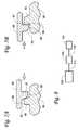
- FIG. 7Ais a schematic diagram depicting the relationship between the ridges when tightening the collet compression member on the housing, i.e., advancing the collet compression member in the proximal direction.
- FIG. 7Bis a schematic diagram depicting the relationship between the ridges when loosening the collet compression member on the housing, i.e., advancing the collet compression member in the distal direction.
- FIG. 8depicts one illustrative embodiment of a system including a fluid coupling as described herein.
- FIG. 9is an exploded diagram of one alternative fluid coupling that can be used in fluid delivery catheters as described herein.
- FIG. 10is a cross-sectional view of the fluid coupling depicted in FIG. 9 (after assembly of the fluid coupling).
- FIG. 11is an enlarged cross-section view of the retention mechanism provided between the housing 220 and the sleeve 240 as seen in FIG. 10 .
- FIG. 1is an exploded assembly diagram depicting the various component that may be provided in some embodiments of the fluid couplings as described herein, while FIG. 2 is an enlarged cross-sectional view of the fluid coupling 10 after the components have been assembled.
- FIG. 3is an exploded cross-sectional view of some of the components in the fluid coupling of FIGS. 1 and 2 proceeding from the proximal end towards the distal end, while FIG. 4 is an exploded cross-sectional view of some of the components of the fluid coupling of FIGS. 1 and 2 proceeding from the distal end towards the proximal end.
- the coupling 10is used to effect a fluid connection between a supply line 14 and a delivery tube 16 .
- the depicted embodiment of the fluid coupling 10includes a proximal end 11 and a distal end 12 , and the components of the fluid coupling 10 are assembled along a longitudinal axis 13 .
- the various components in the fluid couplings as described hereinmay be described as having a proximal end and/or a distal end.
- the proximal end of any such componentis the end of the component that is nearest the proximal end 11 of the fluid coupling 10 and the distal end of any such component is the end of the component that is nearest the distal end 12 of the fluid coupling 10 .
- the fluid coupling 10 depicted in FIGS. 1-4includes a housing 20 , a sleeve 40 that fits within the housing 20 , a collet 50 that fits within the sleeve 40 , and a compliance member 60 that fits at least partially within the sleeve 40 on the distal end of the sleeve 40 .
- the fluid coupling 10also includes a compression member 80 and distal cap member 90 that retain the various components within the housing 20 from the distal end.
- the fluid coupling 10 of FIGS. 1-4also includes an optional guide member 70 that fits within the sleeve 40 .
- the housing 20 of the fluid coupling 10includes a primary bore 22 having an opening 27 that faces the distal end 12 of the fluid coupling 10 .
- the primary bore 22includes a proximal face 23 at its proximal end (i.e., the end of the primary bore 22 closest to the proximal end 11 of the fluid coupling 10 ).
- the housing 20also includes a supply line passage 26 formed therein, the supply line passage 26 extending from the proximal end 21 of the housing 20 to an opening 25 in the proximal face 23 of the primary bore 22 such that fluid passing through the supply line passage 26 in a distal direction (i.e., towards the distal end 12 of the fluid coupling 10 ) is delivered towards the primary bore 22 through the opening 25 in the proximal face 23 .
- the supply line passage 26is preferably large enough such that a supply line 14 (as seen in FIG. 2 ) can be inserted into the supply line passage 26 to deliver fluid into the fluid coupling 10 from the proximal end 11 of the fluid coupling 10 .
- the housing 20is provided in two subcomponents in the form of a housing insert 28 and a proximal cap 30 .
- a supply line 14 inserted into the supply line passage 26(as depicted in FIG. 2 ) be fixedly attached to the housing insert 28 .
- the attachment between the supply line 14 and the supply line passage 26may be made by any suitable technique. If the supply line 14 and the housing insert 28 are constructed of metal (e.g., titanium, stainless steel, etc.), the supply line 14 may be attached to the housing insert 28 by a circumferential lap weld between the supply line 14 and the housing insert 28 (in zone 29 as depicted in FIG. 2 ).
- the housing insert 28is located within a cavity 32 in the proximal cap 30 .
- the housing insert 28may be fixedly attached to the proximal cap 30 such that rotation of the housing insert 28 within the cavity 32 is restricted, while in other embodiments, the housing insert 28 may be allowed to rotate about the longitudinal axis 13 within the cavity 32 .
- fluid coupling 10includes a strain relief collar 34 attached to the proximal end 21 of the housing 20 , such that a supply line 14 attached to the housing 20 extends through a lumen 35 in the strain relief collar 34 before entering the supply line passage 26 .
- the strain relief collar 34provides support to the supply line 14 to restrict bending of the supply line 14 at the point where the supply line 14 enters the proximal end 11 of the fluid coupling 10 .
- An additional strain reliefmay also be utilized on the distal end for similar purposes with the delivery tube.
- the strain relief collar 34can be manufactured of many different materials, although it may be preferred that the materials used for the strain relief be resiliently flexible.
- thermoplastic polyester elastomerse.g., HYTREL (available from DuPont)
- thermoplastic elastomerse.g., SANTOPRENE (available from Exxon Mobil Corporation)
- the proximal cap 30may preferably include external features such as, e.g., fins 36 or other structures that can assist in manual control over rotation of the housing 20 about the longitudinal axis 13 .
- the housing insert 28may preferably be constructed of metal (e.g., stainless steel, brass, etc.) while the proximal cap 30 may preferably be constructed of polymeric materials (e.g., polyester, polycarbonate, etc.).
- the strain relief collar 34may be fixedly attached to the proximal cap 30 by any suitable technique, e.g., adhesives, overmolding, welding (thermal, chemical, etc.), snap-fitting, friction fit, etc.
- the housing 20may also preferably include threads 24 that cooperate with threads 87 on the compression member 80 to compress the components located between and/or within the housing 20 and the compression member 80 as described herein.
- the threads 24may be provided on the proximal cap 30 (as depicted) and/or on the housing insert 28 .
- the fluid coupling 10also includes sleeve 40 and at least a proximal end of the sleeve 40 is located within the primary bore 22 of the housing 20 .
- the distal end 42 of the sleeve 40extends out of the primary bore 22 , but such an arrangement is not required (i.e., the distal end 42 of the sleeve 40 may be located within the primary bore 22 of the housing 20 in some embodiments).
- the sleeve 40further includes a seal end 43 facing the proximal face 23 of the primary bore 22 .
- a seal element 44may be provided and located between the proximal face 23 of the primary bore 22 and the seal end 43 of the sleeve 40 .
- advancement of the collet compression member 80 as described herein in the proximal direction towards the proximal end 11 of the fluid coupling 10compresses the seal element 44 between the seal end 43 of the sleeve 40 and the proximal face 23 of the primary bore 22 .
- the seal element 44is in the form of a compressible O-ring, although the seal element 44 may take a variety of other forms in other embodiments, e.g., a gasket, etc.
- the depicted O-ringhas a circular cross-sectional shape, O-rings/gaskets with other cross-sectional shapes could be used, e.g., square, trapezoidal, lobed (e.g., a four-lobed quad seal), etc.
- seal element 44 in the depicted embodimentis attached to the sleeve 40 (inset into the seal end 43 ), the seal element 44 could alternatively be attached to the proximal face 23 of the primary bore 22 in other embodiments and, in still other embodiments, the seal element 44 could be simply located between the proximal face 23 and the seal end 43 without being attached to either housing 20 or the sleeve 40 .
- a sealmay be formed between the proximal face 23 of the primary bore 22 and the seal end 43 of the sleeve 40 . That seal may be formed by, e.g., compression of the seal end 43 of the sleeve 40 against the proximal face 23 .
- the seal end 43may preferably be made of material that is softer than the material use for the proximal face 23 of the primary bore 22 . Softness may be measured using, e.g., the Shore A hardness scale or any other suitable equivalent.
- the softer material used for the seal end 43 of the sleeve 40may, in some embodiments, conform to the shape of the proximal face 23 of the primary bore 22 to form a seal outside of the seal element 44 such that the flow of fluid from a supply tube 14 between the exterior surface of the sleeve 40 and the primary bore 22 is prevented (or at least substantially restricted).
- the seal end 43may be made of a polymeric material while the proximal face 23 is made of a metal, while in other embodiments, the seal end 43 may be made of a metal that is softer than the metal used for the proximal face 23 of the primary bore 22 .
- the seal end 43 (and perhaps all of) the sleeve 40may be constructed of, e.g., a nylon or another polymer (e.g., acetal, polycarbonate, acrylic, rigid polyurethane, etc.) while the proximal face 23 of the primary bore 22 may be a metal, e.g., stainless steel, brass, etc.
- the sleeve 40also includes a collet bore 45 formed therein that includes a collet compression surface 46 at the proximal end of the collet bore 45 and an opening 47 sized to receive a collet 50 at the distal end of the collet bore 45 .
- the collet compression surface 46 located at the proximal end of the collet bore 45may preferably have a shape that cooperates with the collet 50 to force the collet fingers against a tube passing through the collet 50 as described herein.
- the collet compression surface 46has a conical shape, although other non-conical shapes with tapering surfaces may also be used for the collet compression surfaces described herein.
- the sleeve 40further includes, in the depicted embodiment, a sleeve passage 48 that extends from the proximal end 41 of the sleeve 40 into the collet bore 45 .
- Fluid from, e.g., a supply line located in the supply line passage 26can preferably pass into the collet bore 45 through the sleeve passage 48 (in the absence of any element blocking the fluid passage 48 ).
- the sleeve passage 48be sized to allow a delivery tube as described herein to be advanced through the sleeve passage 48 such that its proximal end is located proximal to the proximal end 41 of the sleeve 40 and the seal element 44 .
- the seal element 44can form a fluid seal around the exterior of the delivery tube to prevent (or at least substantially restrict) fluid leakage around the outside of the delivery tube.
- the delivery tube 16extend through seal element 44 such that the proximal end of delivery tube 16 is proximal to the seal element 44 .
- the embodiment of fluid coupling 10 as depicted in FIGS. 1-4also includes a collet 50 having at least its proximal end located in the collet bore 45 of the sleeve 40 .
- the collet 50preferably includes two or more collet fingers 52 that surround a collet passage 53 that extends from the proximal end of the collet 50 to the distal end of the collet 50 .
- the collet fingers 52 surrounding the collet passage 53preferably extend from a collet base 54 that may be located closer to the distal end of the collet 50 such that the collet fingers 52 are essentially cantilevered from the collet base 54 .
- Each of the collet fingers 52preferably includes an inclined surface 55 proximate the proximal end of the collet 50 .
- collet 50When the collet 50 is assembled in a fluid coupling 10 such that the inclined surfaces 55 of the collet fingers 52 are in contact with the collet compression surface 46 of the sleeve 40 , movement of the collet 50 in the proximal direction towards the proximal end 11 of the coupling 10 forces the collet fingers 52 towards a center of the collet passage 53 . If a delivery tube 16 is located within collet passage 53 , then the fingers 52 are forced against the delivery tube 16 as described herein.
- the forces applied by the collet fingers 52 on the delivery tuberetain the delivery tube in position in the fluid coupling 10 with the proximal end of the delivery tube being located proximal of the proximal end 41 of the sleeve 40 such that the seal element 44 can for a seal around the delivery tube.
- the collet passage 53 of the collet 50may optionally have a minimum collapsed cross-sectional area of at least about 0.05 square millimeter (mm 2 ) or more.
- the collets used in connection with the fluid couplings described hereinmay include collet fingers that do not collapse to close the collet passage 53 in the absence of an article (such as, e.g., a tube, etc.) located in the collet passage 53 .
- FIG. 3Ais an end view taken from the proximal end of the collet 50 (along line 3 A- 3 A in FIG. 3 ) depicting the collet passage 53 with the fingers 52 before compression.
- 3Bis the same view taken when the collet fingers 52 are compressed such that the fingers 52 are all in contact with each other.
- a collet 50may be manufactured by, e.g., boring out a conventional collet to provide the collet passage 53 .
- the collet passage 53may have a minimum collapsed diameter equal to or less than the outer diameter of the delivery tube passing through the collet 50 such that an adequate clamping force may be applied to the tube by the collet fingers 52 .
- the fluid coupling 10 of FIGS. 1-4also includes a compliance element 60 .
- the proximal end of the compliance element 60acts on the collet fingers 52 to force the collet 50 in the proximal direction.
- the compliance element 60 depicted in FIGS. 1-4is in the form of two components, a proximal sleeve 62 and the distal sleeve 64 .
- the proximal end of the proximal sleeve 62is in contact with and acts on the collet fingers 52
- the distal sleeve 64acts on the distal end of the proximal sleeve 62 .
- At least one of the proximal sleeve 62 and the distal sleeve 64include resiliently compressible elastomeric polymer that can be elastically deformed as the collet compression member 80 is advanced in the proximal direction to force the collet 50 into the collet bore 45 of the sleeve 40 as described herein.
- the proximal sleeve 62may be in the form of a tube constructed of a first polymer while the distal sleeve 64 is in the form of a tube constructed of a second polymer, where the second polymer is a resiliently compressible elastomeric polymer.
- the proximal sleeve 62may be constructed of, e.g., a nylon or another polymer (e.g., acetal, polycarbonate, acrylic, rigid polyurethane, etc.), although harder materials such as, e.g., metals, ceramics, etc. could be used).
- the distal sleeve 64is constructed of, e.g., urethane or another resiliently compressible elastomeric polymer (e.g., rubbers, thermoplastic polyurethanes (such as, e.g., PELLETHANE 2363 90A (available from Dow Chemical), etc.), fluoroelastomers (e.g., VITON (available from DuPont Performance Elastomers), etc.), copolymers of butadiene and acrylonitrile (e.g., Buna-N, etc.), etc.).
- urethane or another resiliently compressible elastomeric polymere.g., rubbers, thermoplastic polyurethanes (such as, e.g., PELLETHANE 2363 90A (available from Dow Chemical), etc.), fluoroelastomers (e.g., VITON (available from DuPont Performance Elastomers), etc.), copolymers of butadiene and acrylonitrile (e.g
- the compliance element 60is in the form of two sub-components in the depicted embodiment, in other embodiments the compliance element 60 may be provided as a single component. In such an embodiment, it may be preferred that some or all of the compliance element 60 be constructed of a resiliently compressible elastomeric polymer.
- the embodiment of the fluid coupling 10 depicted in FIGS. 1-4also includes an optional guide member 70 that is sized to fit within the collet 50 in the collet bore 45 of the sleeve 40 .
- the guide member 70includes a distal end 72 having a conical surface leading to a guide bore 74 that extends from the distal end 72 to the proximal end of the guide member 70 .
- the guide member 70may assist in aligning or guiding a delivery tube 16 inserted into the distal end 12 of the fluid coupling 10 with the collet passage 53 such that the delivery tube 16 can be advanced in the proximal direction through the collet passage 53 .
- the guide member 70is optional because, in some embodiments, the guide member 70 may not be required to guide the delivery tube 16 (where, e.g., the collet 50 itself includes guide structures, etc.). If provided, the guide member 70 may be constructed of any suitable material, e.g., polymer, ceramic, glass, metal, etc.
- One relationship that is depicted in the embodiment of the fluid coupling illustrated in FIGS. 1-4is the arrangement of the seal formed by the seal element 44 relative to the collet passage 53 as defined by the collet fingers 52 of the collet 50 .
- the seal formed by seal element 44is located proximally from the collet passage 53 located between collet fingers 52 .
- a delivery tube(see, e.g., delivery tube 16 in FIG. 1 ) is advanced proximally through the collet passage 53 formed by the collet fingers 52 and, further, through the sleeve passage 48 such that the proximal end of the delivery tube is located proximally of the seal element 44 (such that the seal element 44 can form a seal around the exterior surface of the delivery tube).
- the delivery tubeis further advanced proximally such that the proximal end of the delivery tube is located within the distal end of the supply line passage 26 .
- the opening 25 of the supply line passage 26may be slightly widened with respect to the remainder of the supply line passage 26 to facilitate entry of the proximal end of the delivery tube into the opening 25 of the supply line passage 26 .
- the fluid coupling 10 depicted in FIGS. 1-4also includes a collet compression member 80 located on the distal end 12 of the fluid coupling 10 .
- the collet compression member 80includes an inner surface 82 , an outer surface 84 and a tubing passage 83 formed through the collet compression member 80 , from the inner surface 82 to the outer surface 84 , such that a delivery tube 16 can pass through the collet compression member 80 into the fluid coupling 10 .
- the collet compression member 80is preferably engaged with the housing 20 such that the housing 20 and the collet compression member 80 can be advanced towards each other to provide the compressive force necessary to force the inner surface 82 of the collet compression member 80 against the distal end of the compliance member 60 (in the depicted embodiment, against the distal end of the distal sleeve 64 ).
- the compressive force provided by engagement of the collet compression member 80 with the housing 20also forces the proximal end of the compliance member 60 against the collet 50 (in the depicted embodiment, the proximal end of the proximal sleeve 62 is forced against the collet 50 ).
- the compressive force provided by engagement of the collet compression member 80 with the housing 20also forces the inclined surfaces of the collet fingers 52 against the collet compression surface 46 of the sleeve 40 .
- the resultis that the collet fingers 52 are forced inward towards the collet passage 53 such that the collet 50 clamps onto a tube (e.g., a delivery tube 16 ) located within the collet passage 53 .
- the compressive force provided by engagement of the collet compression member 80 with the housing 20also forces the seal end 43 of the sleeve 40 towards the proximal face 23 of the primary bore 22 in the housing 20 . That compressive force may assist in forming seals by compressing the seal element 44 and/or the seal end 43 of the sleeve against the proximal face 23 of the primary bore 22 .
- FIG. 4depicts the collet compression member 80 and the distal ends of the sleeve 40 and compliance member 60 (with the collet 50 and optional guide member 70 removed for clarity).
- the collet compression member 80in the depicted embodiment, includes an inner nut 86 and an outer sleeve 88 .
- the inner nut 86preferably includes threads 87 designed to engage threads 24 on the housing 20 to provide the compressive forces described herein as the collet compression member 80 is advanced in the proximal direction using the threads 87 and the threads 24 on the housing 20 .
- the outer sleeve 88is fitted over the inner nut 86 and may be retained thereon by a lip 89 that fits over the proximal edge 90 of the inner nut 86 .
- the outer sleeve 88may further include ribs 91 or other features on the outer surface to facilitate manual rotation of the outer sleeve 88 .
- the outer surface 92 of the inner nut 86preferably includes one or more ridges 93 that preferably extend outward from the center of the inner nut 86 (where the center is typically defined by the tubing passage 83 of the collet compression member 80 ).
- the depicted ridges 93are oriented radially from the center of the inner nut 86 , they may not necessarily be radially-oriented in all embodiments.
- the inner surface of the outer sleeve 88preferably includes one or more ridges 95 that are located on cantilevered springs 94 that preferably extend inwardly towards the center of the outer sleeve 88 (where the center is typically defined by the tubing passage 83 of the collet compression member 80 ).
- the springs 94are described as cantilevered because they are connected to the outer sleeve 88 at their outside ends, with their inside ends (in the center of the sleeve 88 ) being otherwise unconnected to the outer sleeve 88 .
- each spring 94includes one ridge 95 , although in other embodiments, one or more of the springs 94 may include two or more ridges 95 .
- the ridges 93 on the inner nut 86 and the ridges 95 on the outer sleeve 88preferably interact with each other in a manner that limits the torque that can be applied to the inner nut 86 using the outer sleeve 88 , yet allows for removal or loosening of the inner nut 86 in a manner similar to that found on a ratcheting fuel cap used in the automobile industry.
- the tightening processmay, in some embodiments, provide one or both of tactile and audible feedback for a user as the ridges 93 and 95 interact with each other during the tightening process.
- the interaction between the ridges 93 and 95 on the inner nut 86 and the outer sleeve 88are depicted in FIGS. 7A and 7B .
- the ridge 95may have an inclined surface 96 .
- the ridge 95 having the inclined surface 96rides up and over the ridge 93 on the inner nut 86 .
- FIG. 7Bthe interaction between the ridge 93 on the inner nut 86 and the ridge 95 on the outer sleeve 88 during loosening of the collet compression member 80 is depicted in more detail.
- the ridge 95includes surface 97 and the ridge 93 includes surface 98 that act against each other during movement in the direction of the arrow depicted in FIG. 7B . Because the surfaces 97 and 98 interfere with each other and neither one is inclined, rotation of the outer sleeve 88 about the longitudinal axis 13 in the direction of the arrow in FIG. 7B , causes the inner nut 86 to rotate as well, thereby reducing the compressive force between the collet compression member 80 and the housing 20 as described herein.
- control over the torque (and, thus, the compressive force) that can be applied using the inner nut 86 and the outer sleeve 88can be adjusted by changing the thickness, shape and other features of the springs 94 on which the ridges 95 are located because such changes can change the spring coefficient (and, thus, the force) applied by each spring 94 .
- torque limit controlcan also be affected by changing the inclination angles of the inclined surfaces of the ridges, the interference between the ridges, etc.
- the materials used to construct the ridges 93 and 95 , the springs 94 , the inner nut 86 , and the outer sleeve 88may be selected to provide a desired torque limit while also maintaining the ability to loosen the inner nut 86 when desired.
- the inner nut 86 and the outer sleeve 88may be constructed of, e.g., metals, polymers (e.g., polycarbonates, nylons, polyethylenes, acetals, etc.).
- the upper end of the torque limits provided by a collet compression member 80 as described hereinmay be on the order of, e.g., 1.4 Newton meters (about 12 in-lbs.) or less, in some embodiments 1.1 Newton meters (about 10 in-lbs.) or less. It may be preferred that the collet compression member 80 be capable of providing at least 0.7 Newton meters (about 6 in-lbs.) of torque.
- the collet compression member 80includes an inner nut 86 and an outer sleeve 88
- the collet compression member 80may be provided in the form of a one-piece cap with threads and inner surface that is designed to work with the remainder of the fluid coupling as described herein. Such embodiments will not, however, typically provide the torque-limiting function of the two-piece collet compression member 80 as described herein.
- the collet compression members used in the fluid couplings described hereinmay, in some embodiments, include features designed to retain the collet compression members on the fluid coupling even when the threads or other features used to provide the compressive force on the collet are not engaged. Examples of such features may include interfering shoulders on the inner surfaces of the inner nut 86 and the outer surface of the housing 20 that interfere with each other in a manner that restricts removal of the collet compression member from the fluid coupling when the collet compression member is not being used to compress the collet as described herein. In addition, restricting removal of the collet compression member from the fluid coupling even when they are not being used to compress the collet can be useful for retaining all of the components of the fluid coupling properly assembled.
- the fluid couplings described hereinmay be provided in infusion flow systems, more specifically, the fluid couplings may be used in systems that include thrombectomy catheters or infusion flow guidewires as described in, e.g., U.S. Pat. No. 6,805,684 (Bonnette et al.); U.S. Pat. No. 6,875,193 (Bonnette et al.); U.S. Pat. No. 6,755,803 (Le et al.); U.S. Patent Application Publication US 2006/0064123 A1 (Bonnette et al.); U.S. Patent Application Publication No.
- FIG. 8An illustrative embodiment of one system in which the fluid couplings described herein may be used is depicted schematically in FIG. 8 , where a system 100 includes fluid supply apparatus 102 that is connected to a catheter 104 through a fluid coupling 110 .
- the fluid supply apparatus 102may include, e.g., a reservoir for containing a fluid to be delivered and a fluid pump capable of moving fluid from the reservoir to the fluid coupling 110 through the supply tubing 114 (See for example the systems disclosed in U.S. Pat. No. 7,935,077 (Thor et al.) or U.S. Pat. No. 7,094,216 (Trombley et al.) both of which are incorporated herein by reference).
- supply tubing 114fluidly connects the fluid supply apparatus 102 to the fluid coupling 110 .
- delivery tubing 116carries fluid distally away from the fluid coupling 110 and the fluid supply apparatus 102 into and/or through the catheter 104 .
- the operating pressures of the fluid delivery systems in which the fluid couplings described herein may be usedmay, for example, range from 50 psi to 20,000 psi.
- the fluid delivery tubing 116may, in some embodiments, be circular tubes with an outside diameter of about 0.014 inch (0.35 mm) and in inside diameter of about 0.010 inch (0.25 mm), although other tube profiles and/or dimensions may be used.
- the infusion flow systems described hereinmay include a fluid coupling 110 that is capable of delivering fluid from the supply tubing 114 to the delivery tubing 116 when the fluid supply apparatus 102 delivers fluid into the supply tubing 114 at pressures of 10,000 psi or higher.
- the infusion flow systems described hereinmay include a fluid coupling 110 that is capable of delivering fluid from the supply tubing 114 to the delivery tubing 116 when the fluid supply apparatus 102 delivers fluid into the supply tubing 114 at pressures of 15,000 psi or higher.
- the delivery tubing 116may have an outer diameter of 1 millimeter or less, while in other embodiments, the delivery tubing 116 may have an outer diameter of 0.5 millimeter or less.
- FIG. 9is an exploded assembly diagram depicting the various component that may be provided in another illustrative embodiment of a fluid couplings as described herein (and which may be used in the system of FIG. 8 ), while FIG. 10 is an enlarged cross-sectional view of the fluid coupling 210 after the components have been assembled.
- the coupling 210is used to effect a fluid connection between a supply line 214 and a delivery tube 216 (see, e.g., FIG. 9 ).
- the alternative fluid coupling 210 depicted in FIGS. 9 and 10includes a proximal end 211 and a distal end 212 , and the components of the fluid coupling 210 are assembled along a longitudinal axis 213 .
- the various components in the fluid coupling 210 as described hereinmay be described as having a proximal end and/or a distal end.
- the proximal end of any such componentis the end of the component that is nearest the proximal end 211 of the fluid coupling 210 and the distal end of any such component is the end of the component that is nearest the distal end 212 of the fluid coupling 210 .
- the fluid coupling 210 depicted in FIGS. 9-10includes a housing 220 .
- a piston 270 , seal element 260 , and a sleeve 240are arranged within the housing 220 as depicted.
- a collet 250is fitted within the sleeve 240 and a collet compression member 280 retains the collet 250 within the sleeve 240 .
- the housing 220 of the fluid coupling 210includes a primary bore 222 having an opening 227 that faces the distal end 212 of the fluid coupling 210 .
- the primary bore 222includes a proximal face 223 at its proximal end (i.e., the end of the primary bore 222 closest to the proximal end 211 of the fluid coupling 210 ).
- the housing 220also includes a supply line passage 226 formed therein, the supply line passage 226 extending from the proximal end 221 of the housing 220 to an opening 225 in the proximal face 223 of the primary bore 222 such that fluid passing through the supply line passage 226 in a distal direction (i.e., towards the distal end 212 of the fluid coupling 210 ) is delivered into the primary bore 222 through the opening 225 in the proximal face 223 .
- the supply line passage 226is preferably large enough such that a supply line 214 can be inserted into the supply line passage 226 to deliver fluid into the fluid coupling 210 from the proximal end 211 of the fluid coupling 210 .
- the fluid coupling 210includes a strain relief collar 234 attached to the proximal end 221 of the housing 220 , such that a supply line attached to the housing 220 extends through a lumen 235 in the strain relief collar 234 before entering the supply line passage 226 .
- the strain relief collar 234preferably restricts kinking of the supply line 214 at the point where the supply line 214 enters the proximal end 211 of the fluid coupling 210 .
- the strain relief collar 234may be fixedly attached to the housing 220 by any suitable technique, e.g., adhesives, overmolding, welding (thermal, chemical, etc.). An additional strain relief, not shown, may also be utilized on the distal end for similar purposes with the delivery tube.
- the housing 220may, in some embodiments, include external features such as, e.g., fins or other structures that can assist in manual control over rotation of the housing 220 about the longitudinal axis 213 .
- the fluid coupling 220includes a piston 270 located within the primary bore 222 of the housing 220 .
- the piston 270includes a high pressure face 271 at its proximal end 271 , with the high pressure face 271 facing the proximal face 223 of the primary bore 222 .
- the piston 270also includes a seal tip 272 that includes a seal surface 273 at the distal end of the piston 270 .
- the seal surface 273faces the sleeve 240 and is located in a seal cavity 242 formed in the sleeve 240 . In the depicted embodiment, the seal surface 273 acts on the seal element 260 located in the seal cavity 242 of the sleeve 240 .
- the high pressure face 271 of the piston 270has a surface area facing the proximal direction that is greater than the surface area of the seal surface 273 that acts on the seal element 260 . That difference in the relative surface areas may be useful in amplifying or concentrating the compressive force delivered to the seal element 260 by the seal surface 273 of the piston 270 .
- the force delivered by the piston 270is a function of the surface area of the high pressure face 271 and the fluid pressure of any fluid delivered to the primary bore 222 by a supply line threaded into the proximal end 211 of the coupling 210 . That force is then largely transferred to the seal element 260 by the seal surface 273 of the piston 270 .
- the piston 270also includes a piston passage 276 that extends through the piston from the high pressure face 271 at its proximal end to the seal surface 273 of the seal tip 272 at the distal end of the piston.
- the piston passage 276provides a path through which fluid from the opening 225 in the proximal face 223 can flow through the piston 270 towards the distal end of the fluid coupling 210 .
- the fluid coupling 210also includes a piston seal 274 located between the proximal end and the distal end of the piston 270 .
- the piston seal 274preferably functions to prevent fluid delivered into the primary bore 222 (through opening 225 in the proximal face 223 ) from flowing between an exterior surface of the piston 270 and an interior surface of the primary bore 222 to the distal end of the piston 270 .
- the piston seal 274may take many different forms (e.g., gaskets, etc.).
- piston seal 274is in the form of an O-ring has a circular cross-sectional shape
- O-rings/gaskets with other cross-sectional shapescould be used, e.g., square, trapezoidal, lobed (e.g., a four-lobed quad seal), etc. Regardless of its form, it may be preferred that the seal 274 allows for translational movement of the piston 270 within the primary bore 222 while still performing its sealing functions.
- the fluid coupling 210also includes sleeve 240 and at least a proximal end of the sleeve 240 is located within the primary bore 222 of the housing 220 .
- the distal end of the sleeve 240is located outside of the primary bore 222 , but such an arrangement is not required (i.e., the distal end of the sleeve 240 may potentially be located within the primary bore 222 of the housing 220 in some embodiments).
- the sleeve 240further includes a seal cavity 242 facing the piston 270 and the proximal face 223 of the primary bore 222 , with the piston 270 located between the sleeve 240 and the proximal face 223 of the primary bore 222 .
- the seal cavity 242opens towards the piston 270 and the proximal face 223 of the primary bore 222 and receives (at least partially) the seal tip 272 such that the seal surface 273 is located within the seal cavity 242 .
- a seal element 260is located within the seal cavity 242 between the seal surface 273 of the piston 270 and a terminal surface 244 of the seal cavity 242 (where the terminal surface 244 of the seal cavity 242 is located at the distal end of the seal cavity 242 ).
- the seal element 260includes a seal element passage 262 extending through the seal element 260 from its proximal end to its distal end such that, for example, a delivery tube (seen in FIG. 9 , but not in FIG. 10 ) can extend through the seal element 260 from the distal end 213 of the fluid coupling 210 .
- the seal element 260preferably includes resiliently compressible elastomeric polymer in its construction such that when the piston 270 is forced in the distal direction (by, e.g., high pressure fluid located between the proximal face 223 of the primary bore 222 and the high pressure face 271 of the piston 270 ), the seal element 260 is compressed within the seal cavity 242 between the seal surface 273 and the terminal surface 244 of the seal cavity 242 . That compression preferably causes the seal element 260 to form a seal around an exterior surface of delivery tubing passing through the seal element passage 262 .
- An optional biasing element 266may be provided in the primary bore 222 of the housing 220 of the fluid coupling 210 .
- the biasing element 266is located in the primary bore 222 such that it forces the piston 270 proximally away from the sleeve 240 .
- the biasing element 266may not be needed if the seal element 260 is resilient enough to move the piston 270 in the proximal direction towards the proximal face 223 of the primary bore 222 in the absence of high pressure fluid acting on the high pressure face 271 of the piston 270 .
- the sleeve 240preferably resists movement in the distal direction, such that the sleeve 240 acts as a stop for the biasing element 266 .
- the sleeve 240can provide that stop function because the sleeve 240 is preferably retained within the primary bore 222 by a retention mechanism such that the sleeve 240 , once inserted into the primary bore 222 , cannot be removed without in some way releasing the retention mechanism.
- FIG. 11which is an enlarged cross-section view of the retention mechanism provided in the embodiment depicted in FIGS.
- the retention mechanismis provided in the form of a first snap-fit feature (e.g., lip 228 ) formed in the interior surface of the primary bore 222 and a second snap fit feature (e.g., lip 227 ) formed in the outer surface of the sleeve 240 .
- the first lip 228 in the primary bore 222 and the second lip 227 on the sleeve 240act against each other after insertion of the sleeve 240 into the primary bore 222 to prevent removal of the sleeve 240 from the primary bore 222 in the absence of distortion of the sleeve 240 and/or the housing 220 .
- retention mechanismscould be substituted for the depicted mechanism provided the retention mechanisms are capable of retaining the sleeve 240 in the primary bore 222 .
- retention mechanismsmay include, but are not limited to, a threaded or snap-fit collar positioned over the distal end of the housing 220 , etc.
- adhesives, weldingthermal, chemical, etc.
- the biasing element 266 as depicted in FIGS. 9-10is in the form of a coil spring, although where a biasing element is provided, many other basing elements could be used in place of or in addition to a coil spring, e.g., resilient elastomeric plugs, etc.
- the sleeve 240includes a collet bore 245 formed therein that includes a collet compression surface 246 at the proximal end of the collet bore 245 and an opening sized to receive a collet 250 at the distal end of the collet bore 245 .
- the sleeve 240further includes, in the depicted embodiment, a fluid passage 248 that extends from the seal cavity 242 into the collet bore 245 .
- Fluid from, e.g., a supply line located in the supply line passage 226can preferably pass into the collet bore 245 through the fluid passage 248 (in the absence of any element blocking the fluid passage 248 ).
- the fluid passage 248be sized to allow a delivery tube as described herein to be advanced through the fluid passage 248 such that its proximal end is located proximal to the seal element 260 . It is preferred at higher pressures that the proximal end of the delivery tube be advanced proximally through the fluid coupling 210 from the distal end 212 until the proximal end of the delivery tube is located within the supply line passage 226 of the housing 220 .
- the collet 250preferably includes at least its proximal end located in the collet bore 245 of the sleeve 240 .
- Collet 250 used in fluid coupling 210is preferably similar to collet 50 described herein in connection with fluid coupling 10 , i.e., collet 250 preferably includes two or more collet fingers 252 that surround a collet passage 253 that extends from the proximal end of the collet 250 to the distal end of the collet 250 . It is preferred that fluids can pass into the collet passage from the collet bore 245 of the sleeve 240 when the collet 250 is located in the collet bore 245 of the sleeve 240 .
- the collet compression surface 246 located at the proximal end of the collet bore 245may preferably have a shape cooperates with the collet 250 to force the collet fingers 252 against a delivery tube passing through the collet passage 253 as described herein.
- the collet compression surface 246has a conical shape, although other non-conical shapes with tapering surfaces may also be used for the collet compression surfaces described herein.
- the collet fingers 252 surrounding the collet passage 253preferably extend from a collet base 254 that may be located closer to the distal end of the collet 250 such that the collet fingers 252 are essentially cantilevered from the collet base 254 .
- Each of the collet fingers 52preferably includes an inclined surface proximate the proximal end of the collet 250 .
- the collet passage 253 of the collet 250may optionally have a minimum collapsed cross-sectional area of at least about 0.05 square millimeters (mm 2 ) or more.
- the collets used in connection with the fluid couplings described hereinmay include collet fingers that do not close the collet passage 253 when collapsed in the absence of an article (such as, e.g., a tube, etc.) located in the collet passage 253 (see, e.g. FIGS. 3 and 3A and the corresponding discussion in connection with collet 50 ).
- the collet passage 253may have a minimum collapsed diameter that is equal to or less than the outer diameter of the tube passing through the collet 250 such that an adequate clamping force may be applied to the tube by the collet fingers 252 .
- the fluid coupling 210 depicted in FIGS. 9-10also includes a collet compression member 280 located on the distal end 212 of the fluid coupling 210 .
- the collet compression member 280includes an inner surface 282 , an outer surface 284 and a tubing passage 283 formed through the collet compression member 280 , from the inner surface 282 to the outer surface 284 , such that a delivery tube can pass through the collet compression member 280 into the fluid coupling 210 .
- the collet compression member 280is preferably engaged with the sleeve 240 such that the sleeve 240 and the collet compression member 280 can be advanced towards each other to provide the compressive force need to force the inner surface 282 of the collet compression member 280 against the distal end of the collet 250 .
- the sleeve 240 and the collet compression member 280may include complementary threads 286 such that rotation of the collet compression member 280 about the axis 213 moves the collet compression member 280 in the proximal direction.
- the collet compression member 280could extend to the housing 220 and connect their (by, e.g., threads, etc.) rather than the sleeve 240 .
- threads 286are used in the depicted embodiment, any other suitable connection could be used in place of threads, e.g., a ratcheting connection, snap fitting, etc.
- the compressive force provided by engagement of the collet compression member 280 with the sleeve 240also forces the inclined surfaces of the collet fingers 252 against the collet compression surface 246 of the sleeve 240 .
- the resultis that the collet fingers 252 are forced inward towards the collet passage 253 such that the collet 250 clamps onto a tube located within the collet passage 253 .
- the collet compression member 280may include torque-limiting features such as those described in connection with the collet compression member 80 of fluid coupling 10 (e.g., an inner nut and an outer sleeve that cooperate to limit the torque that can be applied to the inner nut and, therefore, the force that can be applied to the collet).
- torque-limiting featuressuch as those described in connection with the collet compression member 80 of fluid coupling 10 (e.g., an inner nut and an outer sleeve that cooperate to limit the torque that can be applied to the inner nut and, therefore, the force that can be applied to the collet).
- the various components of the fluid coupling 210may be manufactured of any suitable material or combination of materials (e.g., polymers, metals, ceramics, composites, etc.), although, as discussed herein, it may be preferred that the materials used for the strain relief, seal element, etc. be resiliently flexible.
Landscapes
- Health & Medical Sciences (AREA)
- Heart & Thoracic Surgery (AREA)
- Life Sciences & Earth Sciences (AREA)
- Hematology (AREA)
- Anesthesiology (AREA)
- Biomedical Technology (AREA)
- Engineering & Computer Science (AREA)
- Pulmonology (AREA)
- Animal Behavior & Ethology (AREA)
- General Health & Medical Sciences (AREA)
- Public Health (AREA)
- Veterinary Medicine (AREA)
- Biophysics (AREA)
- Infusion, Injection, And Reservoir Apparatuses (AREA)
- Surgical Instruments (AREA)
Abstract
Description
Claims (20)
Priority Applications (1)
| Application Number | Priority Date | Filing Date | Title |
|---|---|---|---|
| US13/814,804US9238119B2 (en) | 2010-08-12 | 2011-08-11 | Infusion flow system and fluid coupling |
Applications Claiming Priority (3)
| Application Number | Priority Date | Filing Date | Title |
|---|---|---|---|
| US37308010P | 2010-08-12 | 2010-08-12 | |
| PCT/US2011/047409WO2012021697A1 (en) | 2010-08-12 | 2011-08-11 | Infusion flow system and fluid coupling |
| US13/814,804US9238119B2 (en) | 2010-08-12 | 2011-08-11 | Infusion flow system and fluid coupling |
Publications (2)
| Publication Number | Publication Date |
|---|---|
| US20130138086A1 US20130138086A1 (en) | 2013-05-30 |
| US9238119B2true US9238119B2 (en) | 2016-01-19 |
Family
ID=45567941
Family Applications (1)
| Application Number | Title | Priority Date | Filing Date |
|---|---|---|---|
| US13/814,804Active2033-01-17US9238119B2 (en) | 2010-08-12 | 2011-08-11 | Infusion flow system and fluid coupling |
Country Status (4)
| Country | Link |
|---|---|
| US (1) | US9238119B2 (en) |
| EP (1) | EP2603254A4 (en) |
| JP (1) | JP5877294B2 (en) |
| WO (1) | WO2012021697A1 (en) |
Cited By (2)
| Publication number | Priority date | Publication date | Assignee | Title |
|---|---|---|---|---|
| US10357601B1 (en) | 2016-09-06 | 2019-07-23 | Chrysalis Medical, Inc. | Method and apparatus for fibrin sheath disruption |
| US11602617B2 (en) | 2019-04-18 | 2023-03-14 | Michael Bonnette | Pumpless thrombectomy system |
Families Citing this family (4)
| Publication number | Priority date | Publication date | Assignee | Title |
|---|---|---|---|---|
| CN102525600B (en)* | 2010-12-14 | 2016-06-22 | 周星 | The all-purpose sealed device of lower resistance and perforator for perforator |
| WO2015171416A1 (en)* | 2014-05-07 | 2015-11-12 | St. Jude Medical, Cardiology Division, Inc. | Threaded, locking handle mechanism for attaching to shaft |
| JP6529770B2 (en)* | 2015-01-26 | 2019-06-12 | 株式会社カネカ | Electrode catheter, manufacturing method of electrode catheter |
| CN115426984B (en)* | 2020-04-17 | 2025-06-13 | 奥林巴斯株式会社 | Stent Delivery System |
Citations (196)
| Publication number | Priority date | Publication date | Assignee | Title |
|---|---|---|---|---|
| US1436707A (en) | 1921-08-10 | 1922-11-28 | American Platinum Works | Adjustable and safety regulating device for hypodermic needles |
| US2564804A (en) | 1947-03-24 | 1951-08-21 | Everett Samuel James | Needle mount for hypodermic syringes |
| US3773290A (en) | 1971-06-01 | 1973-11-20 | Sta Rite Industries | Clamping device for a flexible hose |
| US4039266A (en) | 1976-07-19 | 1977-08-02 | Connell John W O | Combination stop collar and cutting tool |
| US4122556A (en) | 1977-03-23 | 1978-10-31 | Stanley Poler | Intra-ocular lens |
| US4166807A (en) | 1976-12-08 | 1979-09-04 | Mitsubishi Gas Chemical Company, Inc. | Oxygen absorbent |
| US4198973A (en) | 1978-03-14 | 1980-04-22 | Johnson & Johnson | Intravenous catheter assembly with fluid flow restriction capability |
| US4294250A (en) | 1979-12-07 | 1981-10-13 | Baxter Travenol Laboratories, Inc. | Luer lock connection device |
| US4332254A (en) | 1980-11-17 | 1982-06-01 | Advanced Catheter Systems, Inc. | System for filling and inflating and deflating a vascular dilating cathether assembly |
| US4439188A (en) | 1980-09-15 | 1984-03-27 | Baxter Travenol Laboratories, Inc. | Tube connector |
| US4447077A (en) | 1981-07-13 | 1984-05-08 | Ramer Test Tools, Inc. | Fitting for smooth wall tubes |
| US4467003A (en) | 1978-12-18 | 1984-08-21 | Safta S.P.A. | Valves for sterilizable flat flexible containers and process for their manufacture |
| US4573966A (en) | 1981-11-24 | 1986-03-04 | Schneider Medintag Ag | Method and apparatus for removing and/or enlarging constricted areas in vessels conducting body fluids |
| US4573470A (en) | 1984-05-30 | 1986-03-04 | Advanced Cardiovascular Systems, Inc. | Low-profile steerable intraoperative balloon dilitation catheter |
| US4636195A (en) | 1982-04-02 | 1987-01-13 | Harvey Wolinsky | Method and apparatus for removing arterial constriction |
| US4646719A (en) | 1984-06-11 | 1987-03-03 | Aries Medical Incorporated | Intra-aortic balloon catheter having flexible torque transmitting tube |
| US4651738A (en) | 1985-08-02 | 1987-03-24 | Baylor College Of Medicine | Method and device for performing transluminal angioplasty |
| US4653539A (en) | 1984-06-12 | 1987-03-31 | Mallinckrodt, Inc. | Self-sealing check valve |
| US4710171A (en) | 1986-06-09 | 1987-12-01 | The Kendall Company | Needle depth setting sheath assembly and needle stop |
| US4710075A (en) | 1986-10-01 | 1987-12-01 | Boehringer Mannheim Corporation | Adjustable drill gauge |
| EP0254885A1 (en) | 1986-07-29 | 1988-02-03 | Sarcem Sa | Remote controlled catheter guide |
| US4733652A (en) | 1985-12-31 | 1988-03-29 | Aisin Seiki Kabushiki Kaisha | Intra-aortic balloon |
| US4758223A (en) | 1986-07-02 | 1988-07-19 | Schneider-Shiley (Usa) Inc. | Inflation device for angioplasty catheter |
| US4787794A (en) | 1983-09-01 | 1988-11-29 | 5W Enterprises, Inc. | Drill press with quick adjusting stop nut assembly |
| EP0313836A2 (en) | 1987-09-30 | 1989-05-03 | Advanced Cardiovascular Systems, Inc. | Pressure monitoring guidewire |
| US4832023A (en) | 1987-06-03 | 1989-05-23 | Mcm Laboratories, Inc. | Method and apparatus for reducing blockage in body channels |
| US4838268A (en) | 1988-03-07 | 1989-06-13 | Scimed Life Systems, Inc. | Non-over-the wire balloon catheter |
| US4865587A (en) | 1987-01-14 | 1989-09-12 | Walling Peter T | Syringe and catheter apparatus |
| US4976689A (en) | 1984-09-18 | 1990-12-11 | Medtronic Versaflex, Inc. | Outer exchange catheter system |
| US4992010A (en) | 1988-11-24 | 1991-02-12 | Fischerwerke Artur Fischer Gmbh & Co Kg | Device for forming an undercut in a drilled hole |
| US5014494A (en) | 1988-09-27 | 1991-05-14 | Sherwood Medical Company | Method of sterilizing medical articles |
| US5045061A (en) | 1990-02-02 | 1991-09-03 | C. R. Bard, Inc. | Balloon catheter and locking guidewire system |
| US5059176A (en) | 1989-12-21 | 1991-10-22 | Winters R Edward | Vascular system steerable guidewire with inflatable balloon |
| US5059178A (en) | 1988-08-03 | 1991-10-22 | Ya Wang D | Method of percutaneously removing a thrombus from a blood vessel by using catheters and system for removing a thrombus from a blood vessel by using catheters |
| US5066286A (en) | 1989-05-07 | 1991-11-19 | Ryan Medical, Inc. | Safety multiple sample luer adapter assembly |
| US5085635A (en) | 1990-05-18 | 1992-02-04 | Cragg Andrew H | Valved-tip angiographic catheter |
| US5106363A (en) | 1988-10-11 | 1992-04-21 | Terumo Kabushiki Kaisha | Blood perfusion system and tube used therein |
| US5135482A (en) | 1985-12-31 | 1992-08-04 | Arnold Neracher | Hydrodynamic device for the elimination of an organic deposit obstructing a vessel of a human body |
| US5147164A (en) | 1991-10-03 | 1992-09-15 | Fraver Paul C | Drill bit depth minder |
| US5167239A (en) | 1991-05-30 | 1992-12-01 | Endomedix Corporation | Anchorable guidewire |
| US5171221A (en) | 1991-02-05 | 1992-12-15 | Target Therapeutics | Single lumen low profile valved balloon catheter |
| US5176692A (en) | 1991-12-09 | 1993-01-05 | Wilk Peter J | Method and surgical instrument for repairing hernia |
| US5178158A (en) | 1990-10-29 | 1993-01-12 | Boston Scientific Corporation | Convertible guidewire-catheter with soft tip |
| US5184627A (en) | 1991-01-18 | 1993-02-09 | Boston Scientific Corporation | Infusion guidewire including proximal stiffening sheath |
| US5196245A (en) | 1991-04-01 | 1993-03-23 | General Electric Company | Irradiation resistant functionally encapped polycarbonate |
| US5195955A (en) | 1989-11-14 | 1993-03-23 | Don Michael T Anthony | Device for removal of embolic debris |
| US5207656A (en) | 1990-04-19 | 1993-05-04 | Cordis Corporation | Medical instrument valve having foam partition member |
| US5209740A (en) | 1991-11-22 | 1993-05-11 | Abbott Laboratories | Catheter adapter having retention notches |
| US5209727A (en) | 1992-01-29 | 1993-05-11 | Interventional Technologies, Inc. | Guide wire with integral angioplasty balloon |
| US5211636A (en) | 1990-10-31 | 1993-05-18 | Lake Region Manufacturing Co., Inc. | Steerable infusion guide wire |
| US5217438A (en) | 1992-07-20 | 1993-06-08 | Dlp, Inc. | Needle stop and safety sheath |
| US5250034A (en) | 1990-09-17 | 1993-10-05 | E-Z-Em, Inc. | Pressure responsive valve catheter |
| US5320604A (en) | 1991-04-24 | 1994-06-14 | Baxter International Inc. | Low-profile single-lumen dual-balloon catheter with integrated guide wire for embolectomy dilatation/occlusion and delivery of treatment fluid |
| US5322508A (en) | 1993-04-08 | 1994-06-21 | Cordis Corporation | Guidewire fluid delivery system and method of use |
| US5324260A (en) | 1992-04-27 | 1994-06-28 | Minnesota Mining And Manufacturing Company | Retrograde coronary sinus catheter |
| US5328472A (en) | 1992-07-27 | 1994-07-12 | Medtronic, Inc. | Catheter with flexible side port entry |
| US5330450A (en) | 1983-01-24 | 1994-07-19 | Icu Medical, Inc. | Medical connector |
| US5334153A (en) | 1992-10-07 | 1994-08-02 | C. R. Bard, Inc. | Catheter purge apparatus and method of use |
| US5368034A (en) | 1992-09-04 | 1994-11-29 | Boston Scientific Corporation | Method and apparatus for thrombolytic therapy |
| US5378236A (en) | 1992-05-15 | 1995-01-03 | C. R. Bard, Inc. | Balloon dilatation catheter with integral detachable guidewire |
| US5380284A (en) | 1993-08-13 | 1995-01-10 | Don Michael; T. Anthony | Obstruction dissolution catheter with variably expanding blocking balloons and method of use |
| US5399658A (en) | 1993-10-29 | 1995-03-21 | Miles Inc. | Gamma-radiation-resistant polycarbonate composition |
| US5413581A (en) | 1990-10-04 | 1995-05-09 | Schneider (Europe) A.G. | Method of using a balloon dilatation catheter and a guidewire |
| US5474194A (en) | 1990-07-09 | 1995-12-12 | Continental White Cap, Inc. | Closure with irreversible color change system |
| US5476450A (en) | 1993-11-04 | 1995-12-19 | Ruggio; Joseph M. | Apparatus and method for aspirating intravascular, pulmonary and cardiac obstructions |
| US5505699A (en) | 1994-03-24 | 1996-04-09 | Schneider (Usa) Inc. | Angioplasty device |
| US5514109A (en) | 1992-12-17 | 1996-05-07 | Thomas J. Fogarty | Adjustable valve having a radially compressible sealing body |
| US5520645A (en) | 1994-10-28 | 1996-05-28 | Intelliwire, Inc. | Low profile angioplasty catheter and/or guide wire and method |
| US5549556A (en) | 1992-11-19 | 1996-08-27 | Medtronic, Inc. | Rapid exchange catheter with external wire lumen |
| US5549557A (en) | 1994-08-05 | 1996-08-27 | Medtronic, Inc. | Catheter balloon proximal heat bond on extended shaft |
| US5554114A (en) | 1994-10-20 | 1996-09-10 | Micro Therapeutics, Inc. | Infusion device with preformed shape |
| US5583047A (en) | 1992-12-10 | 1996-12-10 | W. R. Grace & Co.-Conn. | Method of detecting the permeability of an object to oxygen |
| US5584843A (en) | 1994-12-20 | 1996-12-17 | Boston Scientific Corporation | Shaped wire multi-burr rotational ablation device |
| US5591143A (en) | 1993-04-02 | 1997-01-07 | Medrad Inc. | Luer connector with torque indicator |
| US5688234A (en) | 1996-01-26 | 1997-11-18 | Cardiometrics Inc. | Apparatus and method for the treatment of thrombotic occlusions in vessels |
| US5713917A (en) | 1995-10-30 | 1998-02-03 | Leonhardt; Howard J. | Apparatus and method for engrafting a blood vessel |
| US5775327A (en) | 1995-06-07 | 1998-07-07 | Cardima, Inc. | Guiding catheter for the coronary sinus |
| US5776100A (en) | 1995-09-27 | 1998-07-07 | Interventional Innovations Corporation | Nickel titanium guide wires for occlusion and drug delivery |
| US5779688A (en) | 1994-10-28 | 1998-07-14 | Intella Interventional Systems, Inc. | Low profile balloon-on-a-wire catheter with shapeable and/or deflectable tip and method |
| US5779721A (en) | 1996-07-26 | 1998-07-14 | Kensey Nash Corporation | System and method of use for revascularizing stenotic bypass grafts and other blood vessels |
| US5792179A (en) | 1996-07-16 | 1998-08-11 | Sideris; Eleftherios B. | Retrievable cardiac balloon placement |
| US5794325A (en) | 1996-06-07 | 1998-08-18 | Harris Corporation | Electrically operated, spring-biased cam-configured release mechanism for wire cutting and seating tool |
| US5795325A (en) | 1991-07-16 | 1998-08-18 | Heartport, Inc. | Methods and apparatus for anchoring an occluding member |
| US5807330A (en) | 1996-12-16 | 1998-09-15 | University Of Southern California | Angioplasty catheter |
| US5810871A (en) | 1997-04-29 | 1998-09-22 | Medtronic, Inc. | Stent delivery system |
| US5827324A (en) | 1997-03-06 | 1998-10-27 | Scimed Life Systems, Inc. | Distal protection device |
| US5833644A (en) | 1996-05-20 | 1998-11-10 | Percusurge, Inc. | Method for emboli containment |
| US5833650A (en) | 1995-06-05 | 1998-11-10 | Percusurge, Inc. | Catheter apparatus and method for treating occluded vessels |
| US5843022A (en) | 1995-10-25 | 1998-12-01 | Scimied Life Systems, Inc. | Intravascular device utilizing fluid to extract occlusive material |
| US5865721A (en) | 1993-12-20 | 1999-02-02 | C. R. Bard, Inc. | Intra-aortic balloon catheters |
| US5881534A (en) | 1994-06-08 | 1999-03-16 | Pharmacia & Upjohn Ab | Process for sterilization by radiation and by the use of an oxygen absorber, a container and a medical article sterilized by the process |
| US5925016A (en) | 1995-09-27 | 1999-07-20 | Xrt Corp. | Systems and methods for drug delivery including treating thrombosis by driving a drug or lytic agent through the thrombus by pressure |
| US5957901A (en) | 1997-10-14 | 1999-09-28 | Merit Medical Systems, Inc. | Catheter with improved spray pattern for pharmaco-mechanical thrombolysis therapy |
| US5961510A (en) | 1997-09-26 | 1999-10-05 | Medtronic, Inc. | Flexible catheter |
| US5968017A (en) | 1997-10-14 | 1999-10-19 | Merit Medical Systems, Inc. | Pulse fluid infusion systems |
| US6022336A (en) | 1996-05-20 | 2000-02-08 | Percusurge, Inc. | Catheter system for emboli containment |
| US6027461A (en) | 1995-10-11 | 2000-02-22 | Micro Therapeutics, Inc. | Infusion guidewire having fixed core wire and flexible radiopaque marker |
| US6036715A (en) | 1986-04-15 | 2000-03-14 | Yock; Paul G. | Angioplasty apparatus facilitating rapid exchanges |
| US6050972A (en) | 1996-05-20 | 2000-04-18 | Percusurge, Inc. | Guidewire inflation system |
| US6071285A (en) | 1996-03-25 | 2000-06-06 | Lashinski; Robert D. | Rapid exchange folded balloon catheter and stent delivery system |
| US6080170A (en) | 1996-07-26 | 2000-06-27 | Kensey Nash Corporation | System and method of use for revascularizing stenotic bypass grafts and other occluded blood vessels |
| US6123698A (en) | 1995-11-27 | 2000-09-26 | Therox, Inc. | Angioscopy apparatus and methods |
| US6135991A (en) | 1997-03-06 | 2000-10-24 | Percusurge, Inc. | Aspiration method |
| US6146372A (en) | 1998-12-24 | 2000-11-14 | Datascope Investment Corp | Apparatus and method for the percutaneous insertion of a pediatric intra-aortic balloon catheter |
| US6161695A (en) | 1998-08-21 | 2000-12-19 | Depuy Orthopaedics, Inc. | Protective packaging unit |
| US6166116A (en) | 1999-06-03 | 2000-12-26 | The Dow Chemical Company | Carbonate polymer compositions stabilized against discoloration and physical property deterioration during sterilization by ionizing radiation |
| US6171328B1 (en) | 1999-11-09 | 2001-01-09 | Embol-X, Inc. | Intravascular catheter filter with interlocking petal design and methods of use |
| US6174316B1 (en) | 1998-05-28 | 2001-01-16 | Medtronic, Inc. | Stent delivery system |
| US6176844B1 (en) | 1997-05-22 | 2001-01-23 | Peter Y. Lee | Catheter system for the isolation of a segment of blood vessel |
| US6183420B1 (en) | 1997-06-20 | 2001-02-06 | Medtronic Ave, Inc. | Variable stiffness angioplasty guide wire |
| US6190354B1 (en) | 1994-09-16 | 2001-02-20 | Scimed Life Systems, Inc. | Balloon catheter with improved pressure source |
| US6203561B1 (en) | 1999-07-30 | 2001-03-20 | Incept Llc | Integrated vascular device having thrombectomy element and vascular filter and methods of use |
| US6217567B1 (en) | 1997-03-06 | 2001-04-17 | Percusurge, Inc. | Hollow medical wires and methods of constructing same |
| US6224570B1 (en) | 1998-02-06 | 2001-05-01 | Possis Medical, Inc. | Rheolytic thrombectomy catheter and method of using same |
| US6231588B1 (en) | 1998-08-04 | 2001-05-15 | Percusurge, Inc. | Low profile catheter for angioplasty and occlusion |
| US6241744B1 (en) | 1998-08-14 | 2001-06-05 | Fox Hollow Technologies, Inc. | Apparatus for deploying a guidewire across a complex lesion |
| US6241706B1 (en) | 1999-07-16 | 2001-06-05 | Datascope Investment Corporation | Fast response intra-aortic balloon pump |
| US6245089B1 (en) | 1997-03-06 | 2001-06-12 | Scimed Life Systems, Inc. | Distal protection device and method |
| US6273880B1 (en) | 1998-01-21 | 2001-08-14 | St. Jude Medical Anastomotic Technology Group, Inc. | Catheters with integrated lumen and methods of their manufacture and use |
| US20010014821A1 (en) | 1998-11-16 | 2001-08-16 | Mohamad Ike Juman | Balloon catheter and stent delivery system having enhanced stent retention |
| US20010016704A1 (en) | 1998-02-19 | 2001-08-23 | Gholam Reza Zadno-Azizi | Low profile fluid delivery and sealing system for a catheter |
| US6355016B1 (en) | 1997-03-06 | 2002-03-12 | Medtronic Percusurge, Inc. | Catheter core wire |
| WO2002024271A2 (en) | 2000-09-22 | 2002-03-28 | Kensey Nash Corporation | Systems for delivering agents for revascularizing accluded blood vessels |
| US6387071B1 (en) | 1998-07-15 | 2002-05-14 | Corazon Technologies, Inc. | Methods and devices for reducing the mineral content of vascular calcified lesions |
| US20020096521A1 (en) | 2001-01-22 | 2002-07-25 | Venanzio Cardarelli | Tennis ball container safety shield |
| US20020133117A1 (en) | 1996-05-20 | 2002-09-19 | Gholam-Reza Zadno-Azizi | Low profile catheter valve and inflation adaptor |
| US6475185B1 (en) | 2000-02-24 | 2002-11-05 | Scimed Life Systems, Inc. | Occlusion device |
| US6485657B1 (en) | 1998-06-11 | 2002-11-26 | Teijin, Limited | Gamma-ray stabilizer and thermoplastic polymer compound including the said stabilizer |
| US6488671B1 (en) | 1999-10-22 | 2002-12-03 | Corazon Technologies, Inc. | Methods for enhancing fluid flow through an obstructed vascular site, and systems and kits for use in practicing the same |
| US6494314B1 (en) | 1997-04-10 | 2002-12-17 | Johns Hopkins University | Pre-filled package containing unit dose of medical gas and method of making same |
| US6517518B2 (en) | 2000-03-10 | 2003-02-11 | Kensey Nash Corporation | Tool for facilitating the connecting of a catheter or other tubular member onto a guide-wire without access to the ends of the guide-wire |
| US20030040705A1 (en) | 2001-08-22 | 2003-02-27 | Dorros Gerald Nmi | Apparatus and methods for treating stroke and controlling cerebral flow characteristics |
| US6533767B2 (en) | 2000-03-20 | 2003-03-18 | Corazon Technologies, Inc. | Methods for enhancing fluid flow through an obstructed vascular site, and systems and kits for use in practicing the same |
| US6533751B2 (en) | 2001-01-09 | 2003-03-18 | Andrew Cragg | Micro catheter and guidewire system having improved pushability and control |
| US6533763B1 (en) | 1999-12-06 | 2003-03-18 | James A. Schneiter | Harmonic flow catheter |
| US6544276B1 (en) | 1996-05-20 | 2003-04-08 | Medtronic Ave. Inc. | Exchange method for emboli containment |
| US6569151B1 (en) | 2000-03-10 | 2003-05-27 | Kensey Nash Corporation | Device for connecting a catheter or other tubular member onto a guide-wire without access to the ends of the guide-wire |
| US6612990B1 (en) | 1999-04-08 | 2003-09-02 | Rick L. Pruter | Method and apparatus for guiding needles |
| US20030208134A1 (en) | 2001-05-07 | 2003-11-06 | Secrest Dean J. | Barrett's esophagus cytology device |
| US20040031721A1 (en) | 2000-11-01 | 2004-02-19 | Mann David Marshall | Kit for obtaining an endoarterial biopsy sample |
| US6694832B1 (en) | 2003-02-27 | 2004-02-24 | General Electric Company | Kit and method for setting probe depth |
| US20040039304A1 (en) | 2002-08-23 | 2004-02-26 | Connors John J. | Wire guide |
| US20040039310A1 (en) | 1999-11-30 | 2004-02-26 | Burkett David H. | Wire joint and method |
| WO2004018032A1 (en) | 2002-08-26 | 2004-03-04 | Kensey Nash Corporation | Crimp and cut tool for sealing and unsealing guide wires and tubular instruments |
| US20040050740A1 (en) | 2001-01-25 | 2004-03-18 | Gareth Lewis | Tamper evident packaging |
| US20040059284A1 (en) | 2002-09-24 | 2004-03-25 | Nash John E. | Interventional procedure drive and control system |
| US20040097880A1 (en) | 2002-11-19 | 2004-05-20 | Angiodynamics, Inc. | Combination thrombolytic infusion catheter and dilator system |
| US20040097995A1 (en) | 1996-07-26 | 2004-05-20 | Nash John E. | System and method of use for agent delivery and revascularizing of grafts and vessels |
| US6755803B1 (en) | 1998-02-06 | 2004-06-29 | Possis Medical, Inc. | Single operator exchange fluid jet thrombectomy device |
| US20040133185A1 (en) | 2002-05-21 | 2004-07-08 | Nash John E. | Tool for facilitating the connecting of a catheter or other tubular member onto a guide-wire without access to the ends of the guide wire |
| US6789986B2 (en) | 2001-08-16 | 2004-09-14 | Paul J. Story, Jr. | Stop for a threaded rod |
| US6805684B2 (en) | 1990-08-06 | 2004-10-19 | Possis Medical, Inc. | Thrombectomy catheter and system |
| US20040210164A1 (en) | 2002-08-26 | 2004-10-21 | Mark Eberhart | Guidewire mounted balloon modulation device and methods of use |
| US6824550B1 (en) | 2000-04-06 | 2004-11-30 | Norbon Medical, Inc. | Guidewire for crossing occlusions or stenosis |
| US6830577B2 (en) | 1996-07-26 | 2004-12-14 | Kensey Nash Corporation | System and method of use for treating occluded vessels and diseased tissue |
| US6855136B2 (en) | 2002-04-03 | 2005-02-15 | Gore Enterprise Holdings, Inc. | Infusion catheter having an atraumatic tip |
| US6869417B1 (en) | 2000-03-10 | 2005-03-22 | Kensey Nash Corporation | Tool for facilitating the connecting of a catheter or other tubular member onto a guide-wire without access to the ends of the guide-wire |
| US6875193B1 (en) | 1998-02-06 | 2005-04-05 | Possis Medical, Inc. | Rapid exchange fluid jet thrombectomy device and method |
| US20050075647A1 (en) | 2000-03-10 | 2005-04-07 | Greg Walters | Tool for facilitating the connecting of a catheter or other tubular member onto a guide-wire without access to the ends of the guide-wire |
| US20050080357A1 (en) | 2002-08-26 | 2005-04-14 | Mark Eberhart | Guidewire mounted balloon modulation device and methods of use |
| US20050095891A1 (en)* | 2003-10-31 | 2005-05-05 | Greg Schorn | Connector assembly |
| US6902535B2 (en) | 2002-08-26 | 2005-06-07 | Kansey Nash Corporation | Guide-wire mounted balloon modulation device and methods of use |
| US6927063B2 (en) | 1999-04-22 | 2005-08-09 | Ineos Silicas Limited | Humidity indicators |
| US20050182437A1 (en) | 2001-11-06 | 2005-08-18 | Bonnette Michael J. | Guidewire assembly including a repeatably inflatable occlusive balloon on a guidewire ensheathed with a spiral coil |
| US6932828B2 (en) | 2001-11-06 | 2005-08-23 | Possis Medical, Inc. | Guidewire occlusion system utilizing repeatably inflatable gas-filled occlusive device |
| US6936056B2 (en) | 1996-07-26 | 2005-08-30 | Kensey Nash Corporation | Intravascular system for occluded blood vessels and guidewire for use therein |
| US6942678B2 (en) | 2001-11-06 | 2005-09-13 | Possis Medical, Inc. | Gas inflation/evacuation system and sealing system for guidewire assembly having occlusive device |
| US20050203425A1 (en) | 2004-03-10 | 2005-09-15 | Phil Langston | Coaxial dual lumen pigtail catheter |
| US6962707B2 (en) | 1997-12-02 | 2005-11-08 | Neuralab Limited | Prevention and treatment of amyloidogenic disease |
| US20050271465A1 (en) | 2002-11-25 | 2005-12-08 | Hans-Ulrich Lehmann | Device for making threaded connections, including Luer lock connections |
| US20060064123A1 (en) | 1998-02-06 | 2006-03-23 | Possis Medical, Inc. | Rapid exchange fluid jet thrombectomy device and method |
| US20060074318A1 (en) | 2004-09-27 | 2006-04-06 | Masood Ahmed | Combination sensor guidewire and methods of use |
| WO2006060688A2 (en) | 2004-12-03 | 2006-06-08 | Medrad, Inc. | Fluid delivery system including a fluid path set with sterile check valve connector |
| US20060129126A1 (en) | 2004-11-19 | 2006-06-15 | Kaplitt Michael G | Infusion device and method for infusing material into the brain of a patient |
| US7094216B2 (en) | 2000-10-18 | 2006-08-22 | Medrad, Inc. | Injection system having a pressure isolation mechanism and/or a handheld controller |
| US7141045B2 (en) | 2000-03-20 | 2006-11-28 | Corazon Technologies, Inc. | Methods for enhancing fluid flow through an obstructed vascular site, and systems and kits for use in practicing the same |
| US7169161B2 (en) | 2001-11-06 | 2007-01-30 | Possis Medical, Inc. | Guidewire having occlusive device and repeatably crimpable proximal end |
| US20070060881A1 (en) | 2005-09-01 | 2007-03-15 | Posis Medical, Inc. | Gas inflation/evacuation system incorporating a multiple element valved guidewire assembly having an occlusive device |
| US20070060878A1 (en) | 2005-09-01 | 2007-03-15 | Possis Medical, Inc. | Occlusive guidewire system having an ergonomic handheld control mechanism and torqueable kink-resistant guidewire |
| US20070073271A1 (en) | 2003-11-15 | 2007-03-29 | Brucker Gregory G | Catheter for diagnostic imaging and therapeutic procedures |
| US20070106245A1 (en) | 2005-11-08 | 2007-05-10 | Kerberos Proximal Solutions, Inc. | Infusion guidewire |
| WO2007053779A2 (en) | 2005-11-04 | 2007-05-10 | Medrad, Inc. | Delivery of agents to tissue |
| US7220243B2 (en) | 2001-11-06 | 2007-05-22 | Possis Medical, Inc. | Gas inflation/evacuation system and sealing system incorporating a compression sealing mechanism for guidewire assembly having occlusive device |
| US7219799B2 (en) | 2002-12-31 | 2007-05-22 | Possis Medical, Inc. | Packaging system with oxygen sensor |
| US20070129679A1 (en) | 2005-12-05 | 2007-06-07 | Possis Medical, Inc. | Pneumatic drive unit |
| US7316678B2 (en) | 2003-03-28 | 2008-01-08 | Kensey Nash Corporation | Catheter with associated extension lumen |
| US7334681B2 (en) | 2001-11-06 | 2008-02-26 | Possis Medical, Inc. | Packaging system with oxygen sensor for gas inflation/evacuation system and sealing system |
| US20080097294A1 (en) | 2006-02-21 | 2008-04-24 | Possis Medical, Inc. | Occlusive guidewire system having an ergonomic handheld control mechanism prepackaged in a pressurized gaseous environment and a compatible prepackaged torqueable kink-resistant guidewire with distal occlusive balloon |
| US20080103456A1 (en) | 2006-10-30 | 2008-05-01 | Johnson Benjamin A | Infusion catheter |
| US7374560B2 (en) | 2001-05-01 | 2008-05-20 | St. Jude Medical, Cardiology Division, Inc. | Emboli protection devices and related methods of use |
| US20080188831A1 (en) | 2007-02-06 | 2008-08-07 | Possis Medical, Inc. | Miniature flexible thrombectomy catheter |
| US20080188793A1 (en) | 2007-02-06 | 2008-08-07 | Possis Medical, Inc. | Miniature flexible thrombectomy catheter |
| US7422579B2 (en) | 2001-05-01 | 2008-09-09 | St. Jude Medical Cardiology Divison, Inc. | Emboli protection devices and related methods of use |
| US20080312671A1 (en) | 2007-06-12 | 2008-12-18 | Possis Medical, Inc. | Infusion flow guidewire system |
| US7935077B2 (en) | 2005-09-28 | 2011-05-03 | Medrad, Inc. | Thrombectomy catheter deployment system |
| US8162878B2 (en) | 2005-12-05 | 2012-04-24 | Medrad, Inc. | Exhaust-pressure-operated balloon catheter system |
Family Cites Families (8)
| Publication number | Priority date | Publication date | Assignee | Title |
|---|---|---|---|---|
| US4966585A (en)* | 1988-05-31 | 1990-10-30 | Gangemi Ronald J | Infusion apparatus |
| US5046486A (en)* | 1989-01-13 | 1991-09-10 | Stryker Corporation | Compact pulsing pump for irrigation handpiece |
| US5163903A (en)* | 1989-01-27 | 1992-11-17 | C. R. Bard, Inc. | Catheter exchange system with detachable luer fitting |
| US5102393A (en)* | 1989-07-17 | 1992-04-07 | Survival Technology, Inc. | Autoinjector converted from intramuscular to subcutaneous mode of injection |
| US5788673A (en)* | 1995-06-05 | 1998-08-04 | Atrion Medical Products, Inc. | Drug infusion system |
| GB2365344A (en)* | 2000-08-04 | 2002-02-20 | Alan David Mogg | Catheter adaptor |
| US7140592B2 (en)* | 2002-12-31 | 2006-11-28 | Cardinal Health 303, Inc. | Self-sealing male Luer connector with biased valve plug |
| FR2905273B1 (en)* | 2006-09-06 | 2009-04-03 | Becton Dickinson France Soc Pa | AUTOMATIC INJECTION DEVICE WITH TIMING MEANS. |
- 2011
- 2011-08-11WOPCT/US2011/047409patent/WO2012021697A1/enactiveApplication Filing
- 2011-08-11EPEP11817032.3Apatent/EP2603254A4/ennot_activeWithdrawn
- 2011-08-11JPJP2013524227Apatent/JP5877294B2/enactiveActive
- 2011-08-11USUS13/814,804patent/US9238119B2/enactiveActive
Patent Citations (220)
| Publication number | Priority date | Publication date | Assignee | Title |
|---|---|---|---|---|
| US1436707A (en) | 1921-08-10 | 1922-11-28 | American Platinum Works | Adjustable and safety regulating device for hypodermic needles |
| US2564804A (en) | 1947-03-24 | 1951-08-21 | Everett Samuel James | Needle mount for hypodermic syringes |
| US3773290A (en) | 1971-06-01 | 1973-11-20 | Sta Rite Industries | Clamping device for a flexible hose |
| US4039266A (en) | 1976-07-19 | 1977-08-02 | Connell John W O | Combination stop collar and cutting tool |
| US4166807A (en) | 1976-12-08 | 1979-09-04 | Mitsubishi Gas Chemical Company, Inc. | Oxygen absorbent |
| US4122556A (en) | 1977-03-23 | 1978-10-31 | Stanley Poler | Intra-ocular lens |
| US4198973A (en) | 1978-03-14 | 1980-04-22 | Johnson & Johnson | Intravenous catheter assembly with fluid flow restriction capability |
| US4467003A (en) | 1978-12-18 | 1984-08-21 | Safta S.P.A. | Valves for sterilizable flat flexible containers and process for their manufacture |
| US4294250A (en) | 1979-12-07 | 1981-10-13 | Baxter Travenol Laboratories, Inc. | Luer lock connection device |
| US4439188A (en) | 1980-09-15 | 1984-03-27 | Baxter Travenol Laboratories, Inc. | Tube connector |
| US4332254A (en) | 1980-11-17 | 1982-06-01 | Advanced Catheter Systems, Inc. | System for filling and inflating and deflating a vascular dilating cathether assembly |
| US4447077A (en) | 1981-07-13 | 1984-05-08 | Ramer Test Tools, Inc. | Fitting for smooth wall tubes |
| US4573966A (en) | 1981-11-24 | 1986-03-04 | Schneider Medintag Ag | Method and apparatus for removing and/or enlarging constricted areas in vessels conducting body fluids |
| US4636195A (en) | 1982-04-02 | 1987-01-13 | Harvey Wolinsky | Method and apparatus for removing arterial constriction |
| US5330450A (en) | 1983-01-24 | 1994-07-19 | Icu Medical, Inc. | Medical connector |
| US4787794A (en) | 1983-09-01 | 1988-11-29 | 5W Enterprises, Inc. | Drill press with quick adjusting stop nut assembly |
| US4573470A (en) | 1984-05-30 | 1986-03-04 | Advanced Cardiovascular Systems, Inc. | Low-profile steerable intraoperative balloon dilitation catheter |
| US4646719A (en) | 1984-06-11 | 1987-03-03 | Aries Medical Incorporated | Intra-aortic balloon catheter having flexible torque transmitting tube |
| US4653539A (en) | 1984-06-12 | 1987-03-31 | Mallinckrodt, Inc. | Self-sealing check valve |
| US4976689A (en) | 1984-09-18 | 1990-12-11 | Medtronic Versaflex, Inc. | Outer exchange catheter system |
| US4651738A (en) | 1985-08-02 | 1987-03-24 | Baylor College Of Medicine | Method and device for performing transluminal angioplasty |
| US5135482A (en) | 1985-12-31 | 1992-08-04 | Arnold Neracher | Hydrodynamic device for the elimination of an organic deposit obstructing a vessel of a human body |
| US4733652A (en) | 1985-12-31 | 1988-03-29 | Aisin Seiki Kabushiki Kaisha | Intra-aortic balloon |
| US6036715A (en) | 1986-04-15 | 2000-03-14 | Yock; Paul G. | Angioplasty apparatus facilitating rapid exchanges |
| US4710171A (en) | 1986-06-09 | 1987-12-01 | The Kendall Company | Needle depth setting sheath assembly and needle stop |
| US4758223A (en) | 1986-07-02 | 1988-07-19 | Schneider-Shiley (Usa) Inc. | Inflation device for angioplasty catheter |
| EP0254885A1 (en) | 1986-07-29 | 1988-02-03 | Sarcem Sa | Remote controlled catheter guide |
| US4710075A (en) | 1986-10-01 | 1987-12-01 | Boehringer Mannheim Corporation | Adjustable drill gauge |
| US4865587A (en) | 1987-01-14 | 1989-09-12 | Walling Peter T | Syringe and catheter apparatus |
| US4832023A (en) | 1987-06-03 | 1989-05-23 | Mcm Laboratories, Inc. | Method and apparatus for reducing blockage in body channels |
| EP0313836A2 (en) | 1987-09-30 | 1989-05-03 | Advanced Cardiovascular Systems, Inc. | Pressure monitoring guidewire |
| US4838268A (en) | 1988-03-07 | 1989-06-13 | Scimed Life Systems, Inc. | Non-over-the wire balloon catheter |
| US5059178A (en) | 1988-08-03 | 1991-10-22 | Ya Wang D | Method of percutaneously removing a thrombus from a blood vessel by using catheters and system for removing a thrombus from a blood vessel by using catheters |
| US5014494A (en) | 1988-09-27 | 1991-05-14 | Sherwood Medical Company | Method of sterilizing medical articles |
| US5106363A (en) | 1988-10-11 | 1992-04-21 | Terumo Kabushiki Kaisha | Blood perfusion system and tube used therein |
| US4992010A (en) | 1988-11-24 | 1991-02-12 | Fischerwerke Artur Fischer Gmbh & Co Kg | Device for forming an undercut in a drilled hole |
| US5066286A (en) | 1989-05-07 | 1991-11-19 | Ryan Medical, Inc. | Safety multiple sample luer adapter assembly |
| US5195955A (en) | 1989-11-14 | 1993-03-23 | Don Michael T Anthony | Device for removal of embolic debris |
| US5059176A (en) | 1989-12-21 | 1991-10-22 | Winters R Edward | Vascular system steerable guidewire with inflatable balloon |
| US5045061A (en) | 1990-02-02 | 1991-09-03 | C. R. Bard, Inc. | Balloon catheter and locking guidewire system |
| US5207656A (en) | 1990-04-19 | 1993-05-04 | Cordis Corporation | Medical instrument valve having foam partition member |
| US5085635A (en) | 1990-05-18 | 1992-02-04 | Cragg Andrew H | Valved-tip angiographic catheter |
| US5474194A (en) | 1990-07-09 | 1995-12-12 | Continental White Cap, Inc. | Closure with irreversible color change system |
| US6805684B2 (en) | 1990-08-06 | 2004-10-19 | Possis Medical, Inc. | Thrombectomy catheter and system |
| US5250034A (en) | 1990-09-17 | 1993-10-05 | E-Z-Em, Inc. | Pressure responsive valve catheter |
| US5413581A (en) | 1990-10-04 | 1995-05-09 | Schneider (Europe) A.G. | Method of using a balloon dilatation catheter and a guidewire |
| US5178158A (en) | 1990-10-29 | 1993-01-12 | Boston Scientific Corporation | Convertible guidewire-catheter with soft tip |
| US5211636A (en) | 1990-10-31 | 1993-05-18 | Lake Region Manufacturing Co., Inc. | Steerable infusion guide wire |
| US5184627A (en) | 1991-01-18 | 1993-02-09 | Boston Scientific Corporation | Infusion guidewire including proximal stiffening sheath |
| US5171221A (en) | 1991-02-05 | 1992-12-15 | Target Therapeutics | Single lumen low profile valved balloon catheter |
| US5196245A (en) | 1991-04-01 | 1993-03-23 | General Electric Company | Irradiation resistant functionally encapped polycarbonate |
| US5320604A (en) | 1991-04-24 | 1994-06-14 | Baxter International Inc. | Low-profile single-lumen dual-balloon catheter with integrated guide wire for embolectomy dilatation/occlusion and delivery of treatment fluid |
| US5167239A (en) | 1991-05-30 | 1992-12-01 | Endomedix Corporation | Anchorable guidewire |
| US5795325A (en) | 1991-07-16 | 1998-08-18 | Heartport, Inc. | Methods and apparatus for anchoring an occluding member |
| US6251093B1 (en) | 1991-07-16 | 2001-06-26 | Heartport, Inc. | Methods and apparatus for anchoring an occluding member |
| US5147164A (en) | 1991-10-03 | 1992-09-15 | Fraver Paul C | Drill bit depth minder |
| US5209740A (en) | 1991-11-22 | 1993-05-11 | Abbott Laboratories | Catheter adapter having retention notches |
| US5176692A (en) | 1991-12-09 | 1993-01-05 | Wilk Peter J | Method and surgical instrument for repairing hernia |
| US5209727A (en) | 1992-01-29 | 1993-05-11 | Interventional Technologies, Inc. | Guide wire with integral angioplasty balloon |
| US5324260A (en) | 1992-04-27 | 1994-06-28 | Minnesota Mining And Manufacturing Company | Retrograde coronary sinus catheter |
| US5378236A (en) | 1992-05-15 | 1995-01-03 | C. R. Bard, Inc. | Balloon dilatation catheter with integral detachable guidewire |
| US5217438A (en) | 1992-07-20 | 1993-06-08 | Dlp, Inc. | Needle stop and safety sheath |
| US5410797A (en) | 1992-07-27 | 1995-05-02 | Medtronic, Inc. | Method of making a catheter with flexible side port entry |
| US5328472A (en) | 1992-07-27 | 1994-07-12 | Medtronic, Inc. | Catheter with flexible side port entry |
| US5368034A (en) | 1992-09-04 | 1994-11-29 | Boston Scientific Corporation | Method and apparatus for thrombolytic therapy |
| US5334153A (en) | 1992-10-07 | 1994-08-02 | C. R. Bard, Inc. | Catheter purge apparatus and method of use |
| US5549556A (en) | 1992-11-19 | 1996-08-27 | Medtronic, Inc. | Rapid exchange catheter with external wire lumen |
| US5583047A (en) | 1992-12-10 | 1996-12-10 | W. R. Grace & Co.-Conn. | Method of detecting the permeability of an object to oxygen |
| US5514109A (en) | 1992-12-17 | 1996-05-07 | Thomas J. Fogarty | Adjustable valve having a radially compressible sealing body |
| US5591143A (en) | 1993-04-02 | 1997-01-07 | Medrad Inc. | Luer connector with torque indicator |
| US5322508A (en) | 1993-04-08 | 1994-06-21 | Cordis Corporation | Guidewire fluid delivery system and method of use |
| US5380284A (en) | 1993-08-13 | 1995-01-10 | Don Michael; T. Anthony | Obstruction dissolution catheter with variably expanding blocking balloons and method of use |
| US5399658A (en) | 1993-10-29 | 1995-03-21 | Miles Inc. | Gamma-radiation-resistant polycarbonate composition |
| US5476450A (en) | 1993-11-04 | 1995-12-19 | Ruggio; Joseph M. | Apparatus and method for aspirating intravascular, pulmonary and cardiac obstructions |
| US5865721A (en) | 1993-12-20 | 1999-02-02 | C. R. Bard, Inc. | Intra-aortic balloon catheters |
| US5505699A (en) | 1994-03-24 | 1996-04-09 | Schneider (Usa) Inc. | Angioplasty device |
| US5881534A (en) | 1994-06-08 | 1999-03-16 | Pharmacia & Upjohn Ab | Process for sterilization by radiation and by the use of an oxygen absorber, a container and a medical article sterilized by the process |
| US5549557A (en) | 1994-08-05 | 1996-08-27 | Medtronic, Inc. | Catheter balloon proximal heat bond on extended shaft |
| US6190354B1 (en) | 1994-09-16 | 2001-02-20 | Scimed Life Systems, Inc. | Balloon catheter with improved pressure source |
| US5554114A (en) | 1994-10-20 | 1996-09-10 | Micro Therapeutics, Inc. | Infusion device with preformed shape |
| US5520645A (en) | 1994-10-28 | 1996-05-28 | Intelliwire, Inc. | Low profile angioplasty catheter and/or guide wire and method |
| US5779688A (en) | 1994-10-28 | 1998-07-14 | Intella Interventional Systems, Inc. | Low profile balloon-on-a-wire catheter with shapeable and/or deflectable tip and method |
| US5908405A (en) | 1994-10-28 | 1999-06-01 | Intella Interventional Systems, Inc. | Low profile balloon-on-a-wire catheter with shapeable and/or deflectable tip and method |
| US5584843A (en) | 1994-12-20 | 1996-12-17 | Boston Scientific Corporation | Shaped wire multi-burr rotational ablation device |
| US5833650A (en) | 1995-06-05 | 1998-11-10 | Percusurge, Inc. | Catheter apparatus and method for treating occluded vessels |
| US6021340A (en) | 1995-06-07 | 2000-02-01 | Cardima, Inc. | Guiding catheter for the coronary sinus |
| US5775327A (en) | 1995-06-07 | 1998-07-07 | Cardima, Inc. | Guiding catheter for the coronary sinus |
| US5776100A (en) | 1995-09-27 | 1998-07-07 | Interventional Innovations Corporation | Nickel titanium guide wires for occlusion and drug delivery |
| US5925016A (en) | 1995-09-27 | 1999-07-20 | Xrt Corp. | Systems and methods for drug delivery including treating thrombosis by driving a drug or lytic agent through the thrombus by pressure |
| US6027461A (en) | 1995-10-11 | 2000-02-22 | Micro Therapeutics, Inc. | Infusion guidewire having fixed core wire and flexible radiopaque marker |
| US5843022A (en) | 1995-10-25 | 1998-12-01 | Scimied Life Systems, Inc. | Intravascular device utilizing fluid to extract occlusive material |
| US5713917A (en) | 1995-10-30 | 1998-02-03 | Leonhardt; Howard J. | Apparatus and method for engrafting a blood vessel |
| US6123698A (en) | 1995-11-27 | 2000-09-26 | Therox, Inc. | Angioscopy apparatus and methods |
| US5688234A (en) | 1996-01-26 | 1997-11-18 | Cardiometrics Inc. | Apparatus and method for the treatment of thrombotic occlusions in vessels |
| US6071285A (en) | 1996-03-25 | 2000-06-06 | Lashinski; Robert D. | Rapid exchange folded balloon catheter and stent delivery system |
| US6544276B1 (en) | 1996-05-20 | 2003-04-08 | Medtronic Ave. Inc. | Exchange method for emboli containment |
| US20020133117A1 (en) | 1996-05-20 | 2002-09-19 | Gholam-Reza Zadno-Azizi | Low profile catheter valve and inflation adaptor |
| US5833644A (en) | 1996-05-20 | 1998-11-10 | Percusurge, Inc. | Method for emboli containment |
| US6050972A (en) | 1996-05-20 | 2000-04-18 | Percusurge, Inc. | Guidewire inflation system |
| US6022336A (en) | 1996-05-20 | 2000-02-08 | Percusurge, Inc. | Catheter system for emboli containment |
| US5794325A (en) | 1996-06-07 | 1998-08-18 | Harris Corporation | Electrically operated, spring-biased cam-configured release mechanism for wire cutting and seating tool |
| US5792179A (en) | 1996-07-16 | 1998-08-11 | Sideris; Eleftherios B. | Retrievable cardiac balloon placement |
| US5997558A (en) | 1996-07-26 | 1999-12-07 | Kensey Nash Corporation | System and method or use for revascularizing stenotic bypass grafts and other blood vessels |
| US5938672A (en) | 1996-07-26 | 1999-08-17 | Kensey Nash Corporation | System and method of use for revascularizing stenotic bypass grafts and other blood vessels |
| US20040097995A1 (en) | 1996-07-26 | 2004-05-20 | Nash John E. | System and method of use for agent delivery and revascularizing of grafts and vessels |
| US5779721A (en) | 1996-07-26 | 1998-07-14 | Kensey Nash Corporation | System and method of use for revascularizing stenotic bypass grafts and other blood vessels |
| US6080170A (en) | 1996-07-26 | 2000-06-27 | Kensey Nash Corporation | System and method of use for revascularizing stenotic bypass grafts and other occluded blood vessels |
| US6569147B1 (en) | 1996-07-26 | 2003-05-27 | Kensey Nash Corporation | Systems and methods of use for delivering beneficial agents for revascularizing stenotic bypass grafts and other occluded blood vessels and for other purposes |
| US6843797B2 (en) | 1996-07-26 | 2005-01-18 | Kensey Nash Corporation | System and method of use for revascularizing stenotic bypass grafts and other occluded blood vessels |
| US6830577B2 (en) | 1996-07-26 | 2004-12-14 | Kensey Nash Corporation | System and method of use for treating occluded vessels and diseased tissue |
| US6524323B1 (en) | 1996-07-26 | 2003-02-25 | Kensey Nash Corporation | System and method of use for revascularizing stenotic bypass grafts and other occluded blood vessels |
| US7367982B2 (en) | 1996-07-26 | 2008-05-06 | Kensey Nash Corporation | Method for opening a lumen in an occluded blood vessel |
| US20070118072A1 (en) | 1996-07-26 | 2007-05-24 | Kensey Nash Corporation | System and Method of Use for Revascularizing Stenotic Bypass Grafts and Other Blood Vessels |
| US6936056B2 (en) | 1996-07-26 | 2005-08-30 | Kensey Nash Corporation | Intravascular system for occluded blood vessels and guidewire for use therein |
| US6905505B2 (en) | 1996-07-26 | 2005-06-14 | Kensey Nash Corporation | System and method of use for agent delivery and revascularizing of grafts and vessels |
| US5879361A (en) | 1996-07-26 | 1999-03-09 | Kensey Nash Corporation | System and method of use for revascularizing stenotic bypass grafts and other blood vessels |
| US5807330A (en) | 1996-12-16 | 1998-09-15 | University Of Southern California | Angioplasty catheter |
| US6135991A (en) | 1997-03-06 | 2000-10-24 | Percusurge, Inc. | Aspiration method |
| US5827324A (en) | 1997-03-06 | 1998-10-27 | Scimed Life Systems, Inc. | Distal protection device |
| US6217567B1 (en) | 1997-03-06 | 2001-04-17 | Percusurge, Inc. | Hollow medical wires and methods of constructing same |
| US6355016B1 (en) | 1997-03-06 | 2002-03-12 | Medtronic Percusurge, Inc. | Catheter core wire |
| US6245089B1 (en) | 1997-03-06 | 2001-06-12 | Scimed Life Systems, Inc. | Distal protection device and method |
| US6494314B1 (en) | 1997-04-10 | 2002-12-17 | Johns Hopkins University | Pre-filled package containing unit dose of medical gas and method of making same |
| US5810871A (en) | 1997-04-29 | 1998-09-22 | Medtronic, Inc. | Stent delivery system |
| US6176844B1 (en) | 1997-05-22 | 2001-01-23 | Peter Y. Lee | Catheter system for the isolation of a segment of blood vessel |
| US6183420B1 (en) | 1997-06-20 | 2001-02-06 | Medtronic Ave, Inc. | Variable stiffness angioplasty guide wire |
| US5961510A (en) | 1997-09-26 | 1999-10-05 | Medtronic, Inc. | Flexible catheter |
| US5957901A (en) | 1997-10-14 | 1999-09-28 | Merit Medical Systems, Inc. | Catheter with improved spray pattern for pharmaco-mechanical thrombolysis therapy |
| US5968017A (en) | 1997-10-14 | 1999-10-19 | Merit Medical Systems, Inc. | Pulse fluid infusion systems |
| US6179816B1 (en) | 1997-10-14 | 2001-01-30 | Merit Medical Systems, Inc. | Catheter with uniform spray pattern along infusion length |
| US6962707B2 (en) | 1997-12-02 | 2005-11-08 | Neuralab Limited | Prevention and treatment of amyloidogenic disease |
| US6273880B1 (en) | 1998-01-21 | 2001-08-14 | St. Jude Medical Anastomotic Technology Group, Inc. | Catheters with integrated lumen and methods of their manufacture and use |
| US20060064123A1 (en) | 1998-02-06 | 2006-03-23 | Possis Medical, Inc. | Rapid exchange fluid jet thrombectomy device and method |
| US6755803B1 (en) | 1998-02-06 | 2004-06-29 | Possis Medical, Inc. | Single operator exchange fluid jet thrombectomy device |
| US6875193B1 (en) | 1998-02-06 | 2005-04-05 | Possis Medical, Inc. | Rapid exchange fluid jet thrombectomy device and method |
| US6224570B1 (en) | 1998-02-06 | 2001-05-01 | Possis Medical, Inc. | Rheolytic thrombectomy catheter and method of using same |
| US20010016704A1 (en) | 1998-02-19 | 2001-08-23 | Gholam Reza Zadno-Azizi | Low profile fluid delivery and sealing system for a catheter |
| US6174316B1 (en) | 1998-05-28 | 2001-01-16 | Medtronic, Inc. | Stent delivery system |
| US6485657B1 (en) | 1998-06-11 | 2002-11-26 | Teijin, Limited | Gamma-ray stabilizer and thermoplastic polymer compound including the said stabilizer |
| US6387071B1 (en) | 1998-07-15 | 2002-05-14 | Corazon Technologies, Inc. | Methods and devices for reducing the mineral content of vascular calcified lesions |
| US6231588B1 (en) | 1998-08-04 | 2001-05-15 | Percusurge, Inc. | Low profile catheter for angioplasty and occlusion |
| US6241744B1 (en) | 1998-08-14 | 2001-06-05 | Fox Hollow Technologies, Inc. | Apparatus for deploying a guidewire across a complex lesion |
| US6161695A (en) | 1998-08-21 | 2000-12-19 | Depuy Orthopaedics, Inc. | Protective packaging unit |
| US20010014821A1 (en) | 1998-11-16 | 2001-08-16 | Mohamad Ike Juman | Balloon catheter and stent delivery system having enhanced stent retention |
| US6146372A (en) | 1998-12-24 | 2000-11-14 | Datascope Investment Corp | Apparatus and method for the percutaneous insertion of a pediatric intra-aortic balloon catheter |
| US6612990B1 (en) | 1999-04-08 | 2003-09-02 | Rick L. Pruter | Method and apparatus for guiding needles |
| US6927063B2 (en) | 1999-04-22 | 2005-08-09 | Ineos Silicas Limited | Humidity indicators |
| US6166116A (en) | 1999-06-03 | 2000-12-26 | The Dow Chemical Company | Carbonate polymer compositions stabilized against discoloration and physical property deterioration during sterilization by ionizing radiation |
| US6241706B1 (en) | 1999-07-16 | 2001-06-05 | Datascope Investment Corporation | Fast response intra-aortic balloon pump |
| US6245008B1 (en) | 1999-07-16 | 2001-06-12 | Datascope Investment Corporation | Fast response intra-aortic balloon pump |
| US6203561B1 (en) | 1999-07-30 | 2001-03-20 | Incept Llc | Integrated vascular device having thrombectomy element and vascular filter and methods of use |
| US6488671B1 (en) | 1999-10-22 | 2002-12-03 | Corazon Technologies, Inc. | Methods for enhancing fluid flow through an obstructed vascular site, and systems and kits for use in practicing the same |
| US6171328B1 (en) | 1999-11-09 | 2001-01-09 | Embol-X, Inc. | Intravascular catheter filter with interlocking petal design and methods of use |
| US20040039310A1 (en) | 1999-11-30 | 2004-02-26 | Burkett David H. | Wire joint and method |
| US6533763B1 (en) | 1999-12-06 | 2003-03-18 | James A. Schneiter | Harmonic flow catheter |
| US6475185B1 (en) | 2000-02-24 | 2002-11-05 | Scimed Life Systems, Inc. | Occlusion device |
| US6869417B1 (en) | 2000-03-10 | 2005-03-22 | Kensey Nash Corporation | Tool for facilitating the connecting of a catheter or other tubular member onto a guide-wire without access to the ends of the guide-wire |
| US6872192B2 (en) | 2000-03-10 | 2005-03-29 | Kensey Nash Corporation | Tool for facilitating the connecting of a catheter or other tubular member onto a guide-wire without access to the ends of the guide-wire |
| US20050075647A1 (en) | 2000-03-10 | 2005-04-07 | Greg Walters | Tool for facilitating the connecting of a catheter or other tubular member onto a guide-wire without access to the ends of the guide-wire |
| US6569151B1 (en) | 2000-03-10 | 2003-05-27 | Kensey Nash Corporation | Device for connecting a catheter or other tubular member onto a guide-wire without access to the ends of the guide-wire |
| US6517518B2 (en) | 2000-03-10 | 2003-02-11 | Kensey Nash Corporation | Tool for facilitating the connecting of a catheter or other tubular member onto a guide-wire without access to the ends of the guide-wire |
| US6533767B2 (en) | 2000-03-20 | 2003-03-18 | Corazon Technologies, Inc. | Methods for enhancing fluid flow through an obstructed vascular site, and systems and kits for use in practicing the same |
| US7141045B2 (en) | 2000-03-20 | 2006-11-28 | Corazon Technologies, Inc. | Methods for enhancing fluid flow through an obstructed vascular site, and systems and kits for use in practicing the same |
| US6824550B1 (en) | 2000-04-06 | 2004-11-30 | Norbon Medical, Inc. | Guidewire for crossing occlusions or stenosis |
| WO2002024271A2 (en) | 2000-09-22 | 2002-03-28 | Kensey Nash Corporation | Systems for delivering agents for revascularizing accluded blood vessels |
| US7094216B2 (en) | 2000-10-18 | 2006-08-22 | Medrad, Inc. | Injection system having a pressure isolation mechanism and/or a handheld controller |
| US20040031721A1 (en) | 2000-11-01 | 2004-02-19 | Mann David Marshall | Kit for obtaining an endoarterial biopsy sample |
| US6533751B2 (en) | 2001-01-09 | 2003-03-18 | Andrew Cragg | Micro catheter and guidewire system having improved pushability and control |
| US20020096521A1 (en) | 2001-01-22 | 2002-07-25 | Venanzio Cardarelli | Tennis ball container safety shield |
| US20040050740A1 (en) | 2001-01-25 | 2004-03-18 | Gareth Lewis | Tamper evident packaging |
| US7374560B2 (en) | 2001-05-01 | 2008-05-20 | St. Jude Medical, Cardiology Division, Inc. | Emboli protection devices and related methods of use |
| US7422579B2 (en) | 2001-05-01 | 2008-09-09 | St. Jude Medical Cardiology Divison, Inc. | Emboli protection devices and related methods of use |
| US20030208134A1 (en) | 2001-05-07 | 2003-11-06 | Secrest Dean J. | Barrett's esophagus cytology device |
| US6789986B2 (en) | 2001-08-16 | 2004-09-14 | Paul J. Story, Jr. | Stop for a threaded rod |
| US20030040705A1 (en) | 2001-08-22 | 2003-02-27 | Dorros Gerald Nmi | Apparatus and methods for treating stroke and controlling cerebral flow characteristics |
| US6942678B2 (en) | 2001-11-06 | 2005-09-13 | Possis Medical, Inc. | Gas inflation/evacuation system and sealing system for guidewire assembly having occlusive device |
| US20050182437A1 (en) | 2001-11-06 | 2005-08-18 | Bonnette Michael J. | Guidewire assembly including a repeatably inflatable occlusive balloon on a guidewire ensheathed with a spiral coil |
| US6932828B2 (en) | 2001-11-06 | 2005-08-23 | Possis Medical, Inc. | Guidewire occlusion system utilizing repeatably inflatable gas-filled occlusive device |
| US7169161B2 (en) | 2001-11-06 | 2007-01-30 | Possis Medical, Inc. | Guidewire having occlusive device and repeatably crimpable proximal end |
| US7334681B2 (en) | 2001-11-06 | 2008-02-26 | Possis Medical, Inc. | Packaging system with oxygen sensor for gas inflation/evacuation system and sealing system |
| US7220243B2 (en) | 2001-11-06 | 2007-05-22 | Possis Medical, Inc. | Gas inflation/evacuation system and sealing system incorporating a compression sealing mechanism for guidewire assembly having occlusive device |
| US6855136B2 (en) | 2002-04-03 | 2005-02-15 | Gore Enterprise Holdings, Inc. | Infusion catheter having an atraumatic tip |
| US20040133185A1 (en) | 2002-05-21 | 2004-07-08 | Nash John E. | Tool for facilitating the connecting of a catheter or other tubular member onto a guide-wire without access to the ends of the guide wire |
| US20040039304A1 (en) | 2002-08-23 | 2004-02-26 | Connors John J. | Wire guide |
| US7226425B2 (en) | 2002-08-26 | 2007-06-05 | Kensey Nash Corporation | Crimp and cut tool for sealing and unsealing guide wires and tubular instruments |
| US7004914B2 (en) | 2002-08-26 | 2006-02-28 | Kensey Nash Corporation | Crimp and cut tool for sealing and unsealing guide wires and tubular instruments |
| WO2004018032A1 (en) | 2002-08-26 | 2004-03-04 | Kensey Nash Corporation | Crimp and cut tool for sealing and unsealing guide wires and tubular instruments |
| US20040210164A1 (en) | 2002-08-26 | 2004-10-21 | Mark Eberhart | Guidewire mounted balloon modulation device and methods of use |
| US7048696B2 (en) | 2002-08-26 | 2006-05-23 | Kensey Nash Corporation | Guide-wire mounted balloon modulation device and methods of use |
| US6902535B2 (en) | 2002-08-26 | 2005-06-07 | Kansey Nash Corporation | Guide-wire mounted balloon modulation device and methods of use |
| US20050080357A1 (en) | 2002-08-26 | 2005-04-14 | Mark Eberhart | Guidewire mounted balloon modulation device and methods of use |
| US20060282015A1 (en) | 2002-08-26 | 2006-12-14 | Mark Eberhart | Guide-wire mounted balloon modulation device and methods of use |
| WO2004028592A1 (en) | 2002-09-24 | 2004-04-08 | Kensey Nash Corporation | Pump drive and control system for infusion to and aspiration from a surgical site |
| US20040059284A1 (en) | 2002-09-24 | 2004-03-25 | Nash John E. | Interventional procedure drive and control system |
| US20040097880A1 (en) | 2002-11-19 | 2004-05-20 | Angiodynamics, Inc. | Combination thrombolytic infusion catheter and dilator system |
| US20050271465A1 (en) | 2002-11-25 | 2005-12-08 | Hans-Ulrich Lehmann | Device for making threaded connections, including Luer lock connections |
| US7219799B2 (en) | 2002-12-31 | 2007-05-22 | Possis Medical, Inc. | Packaging system with oxygen sensor |
| US6694832B1 (en) | 2003-02-27 | 2004-02-24 | General Electric Company | Kit and method for setting probe depth |
| US7316678B2 (en) | 2003-03-28 | 2008-01-08 | Kensey Nash Corporation | Catheter with associated extension lumen |
| US20050095891A1 (en)* | 2003-10-31 | 2005-05-05 | Greg Schorn | Connector assembly |
| US20070073271A1 (en) | 2003-11-15 | 2007-03-29 | Brucker Gregory G | Catheter for diagnostic imaging and therapeutic procedures |
| US20080027334A1 (en) | 2004-03-10 | 2008-01-31 | Vascular Solutions, Inc. | Coaxial dual lumen pigtail catheter |
| US20050203425A1 (en) | 2004-03-10 | 2005-09-15 | Phil Langston | Coaxial dual lumen pigtail catheter |
| US20060074318A1 (en) | 2004-09-27 | 2006-04-06 | Masood Ahmed | Combination sensor guidewire and methods of use |
| US20060129126A1 (en) | 2004-11-19 | 2006-06-15 | Kaplitt Michael G | Infusion device and method for infusing material into the brain of a patient |
| WO2006060688A2 (en) | 2004-12-03 | 2006-06-08 | Medrad, Inc. | Fluid delivery system including a fluid path set with sterile check valve connector |
| US20070060878A1 (en) | 2005-09-01 | 2007-03-15 | Possis Medical, Inc. | Occlusive guidewire system having an ergonomic handheld control mechanism and torqueable kink-resistant guidewire |
| US20070060881A1 (en) | 2005-09-01 | 2007-03-15 | Posis Medical, Inc. | Gas inflation/evacuation system incorporating a multiple element valved guidewire assembly having an occlusive device |
| US7935077B2 (en) | 2005-09-28 | 2011-05-03 | Medrad, Inc. | Thrombectomy catheter deployment system |
| WO2007053779A2 (en) | 2005-11-04 | 2007-05-10 | Medrad, Inc. | Delivery of agents to tissue |
| US20070106245A1 (en) | 2005-11-08 | 2007-05-10 | Kerberos Proximal Solutions, Inc. | Infusion guidewire |
| US20070129679A1 (en) | 2005-12-05 | 2007-06-07 | Possis Medical, Inc. | Pneumatic drive unit |
| US8162878B2 (en) | 2005-12-05 | 2012-04-24 | Medrad, Inc. | Exhaust-pressure-operated balloon catheter system |
| US20080097294A1 (en) | 2006-02-21 | 2008-04-24 | Possis Medical, Inc. | Occlusive guidewire system having an ergonomic handheld control mechanism prepackaged in a pressurized gaseous environment and a compatible prepackaged torqueable kink-resistant guidewire with distal occlusive balloon |
| US20080100061A1 (en)* | 2006-10-30 | 2008-05-01 | Medtronic, Inc. | Breakaway connectors and systems |
| US20080103456A1 (en) | 2006-10-30 | 2008-05-01 | Johnson Benjamin A | Infusion catheter |
| US20080188831A1 (en) | 2007-02-06 | 2008-08-07 | Possis Medical, Inc. | Miniature flexible thrombectomy catheter |
| US20080188793A1 (en) | 2007-02-06 | 2008-08-07 | Possis Medical, Inc. | Miniature flexible thrombectomy catheter |
| US20080312671A1 (en) | 2007-06-12 | 2008-12-18 | Possis Medical, Inc. | Infusion flow guidewire system |
| WO2008157204A3 (en) | 2007-06-12 | 2009-02-26 | Possis Medical Inc | Infusion flow guidewire system |
Non-Patent Citations (10)
| Title |
|---|
| ANGIOJET Pump Set, Possis Medical, Inc. corporate website (www.possis.com). |
| CRW (Radionics) Disposable Depth Stops Product No. DS11, DS16, DS18, DS21, DS25 and DS30, CRW Catalog Product Sheet, 2006. |
| International Preliminary Report on Patentability of Related PCT Publication No. WO2008/157204 mailed on Dec. 9, 2008. |
| International Search Report and Written Opinion from corresponding PCT Application No. PCT/US11/47409 mailed on Dec. 11, 2011. |
| International Search Report for related International Application No. PCT/US2008/066646 mail on Dec. 9, 2008. |
| International Search Report of Related PCT Publication No. WO2008/157204, mailed on Dec. 17, 2009. |
| MicroMewi Multiple Side hole Infusion Catheter Data Sheet, Micro Therapeutics, Inc., Feb. 2005. |
| ProStream Infusion Wire Data Sheet, EV3, Sep. 2007. |
| Supplementary European Search Report from related European Patent Application, mailed on Sep. 26, 2011. |
| Supplementary European Search Report issued Dec. 4, 2009 in corresponding European Application No. EP 05772444.5. |
Cited By (2)
| Publication number | Priority date | Publication date | Assignee | Title |
|---|---|---|---|---|
| US10357601B1 (en) | 2016-09-06 | 2019-07-23 | Chrysalis Medical, Inc. | Method and apparatus for fibrin sheath disruption |
| US11602617B2 (en) | 2019-04-18 | 2023-03-14 | Michael Bonnette | Pumpless thrombectomy system |
Also Published As
| Publication number | Publication date |
|---|---|
| EP2603254A4 (en) | 2016-08-24 |
| WO2012021697A1 (en) | 2012-02-16 |
| EP2603254A1 (en) | 2013-06-19 |
| JP2013533095A (en) | 2013-08-22 |
| JP5877294B2 (en) | 2016-03-08 |
| US20130138086A1 (en) | 2013-05-30 |
Similar Documents
| Publication | Publication Date | Title |
|---|---|---|
| US9238119B2 (en) | Infusion flow system and fluid coupling | |
| US7811278B2 (en) | Fluid connector | |
| US7967797B2 (en) | Intravascular valve component with improved valve positioning | |
| US9447892B2 (en) | Pressure activated valve for high flow rate and pressure venous access applications | |
| US8104512B2 (en) | Spout tip retention method | |
| CA2131159A1 (en) | Medical valve | |
| US20150084335A1 (en) | Pipe Coupling System and Methods of Use Thereof | |
| US11123534B2 (en) | Needle-free connector | |
| JP2006102255A (en) | Infusion line connection structure and connector having the connection structure | |
| US5713878A (en) | Hand tightenable high pressure connector | |
| WO2007002027A2 (en) | Multi-diameter tube fitting | |
| US11559676B2 (en) | Medical device with hemostatic valve | |
| EP3194829B2 (en) | Tube connector | |
| AU2016323969A1 (en) | Safety IV catheter with molded-open blood control valve | |
| EP2450071B1 (en) | Infusion device | |
| US20080100062A1 (en) | Coupling Device | |
| US20120065625A1 (en) | Catheter/pump connector with guide surface and system/method for using same | |
| CN110582324B (en) | Hemostatic valve and methods of making and using hemostatic valve | |
| JP4802914B2 (en) | Medical pipe joint and line used for transporting infusion or blood using the same | |
| US20230405295A1 (en) | Cathlock System for Proximally Trimmable Catheter | |
| US12345362B2 (en) | Hose coupling and method for use in analysis systems | |
| EP3807566A1 (en) | Quick coupling joining kit for irrigation hoses | |
| CN212079791U (en) | Speed controller | |
| US10632290B2 (en) | Catheter assembly | |
| AU2023309887A1 (en) | Needle Hub and Injector Using the Same |
Legal Events
| Date | Code | Title | Description |
|---|---|---|---|
| AS | Assignment | Owner name:MEDRAD, INC., PENNSYLVANIA Free format text:ASSIGNMENT OF ASSIGNORS INTEREST;ASSIGNORS:THOR, ERIC J.;BALL, DOUGLAS J.;LEIRFALLOM, LEIF E.;AND OTHERS;REEL/FRAME:026960/0664 Effective date:20110831 | |
| AS | Assignment | Owner name:MEDRAD, INC., PENNSYLVANIA Free format text:ASSIGNMENT OF ASSIGNORS INTEREST;ASSIGNORS:THOR, ERIC J.;BALL, DOUGLAS J.;LEIRFALLOM, LEIF E.;AND OTHERS;REEL/FRAME:029773/0354 Effective date:20110831 | |
| AS | Assignment | Owner name:BAYER MEDICAL CARE INC., PENNSYLVANIA Free format text:CHANGE OF NAME;ASSIGNOR:MEDRAD, INC.;REEL/FRAME:032250/0165 Effective date:20131107 | |
| AS | Assignment | Owner name:BOSTON SCIENTIFIC LIMITED, BERMUDA Free format text:ASSIGNMENT OF ASSIGNORS INTEREST;ASSIGNOR:BAYER MEDICAL CARE INC.;REEL/FRAME:033729/0215 Effective date:20140827 | |
| FEPP | Fee payment procedure | Free format text:PAYOR NUMBER ASSIGNED (ORIGINAL EVENT CODE: ASPN); ENTITY STATUS OF PATENT OWNER: LARGE ENTITY | |
| STCF | Information on status: patent grant | Free format text:PATENTED CASE | |
| MAFP | Maintenance fee payment | Free format text:PAYMENT OF MAINTENANCE FEE, 4TH YEAR, LARGE ENTITY (ORIGINAL EVENT CODE: M1551); ENTITY STATUS OF PATENT OWNER: LARGE ENTITY Year of fee payment:4 | |
| MAFP | Maintenance fee payment | Free format text:PAYMENT OF MAINTENANCE FEE, 8TH YEAR, LARGE ENTITY (ORIGINAL EVENT CODE: M1552); ENTITY STATUS OF PATENT OWNER: LARGE ENTITY Year of fee payment:8 | |
| AS | Assignment | Owner name:BOSTON SCIENTIFIC MEDICAL DEVICE LIMITED, IRELAND Free format text:ASSIGNMENT OF ASSIGNORS INTEREST;ASSIGNOR:BOSTON SCIENTIFIC LIMITED;REEL/FRAME:065580/0083 Effective date:20191231 |