US9238113B2 - Nasal respiratory devices for positive end-expiratory pressure - Google Patents
Nasal respiratory devices for positive end-expiratory pressureDownload PDFInfo
- Publication number
- US9238113B2 US9238113B2US12/877,836US87783610AUS9238113B2US 9238113 B2US9238113 B2US 9238113B2US 87783610 AUS87783610 AUS 87783610AUS 9238113 B2US9238113 B2US 9238113B2
- Authority
- US
- United States
- Prior art keywords
- valve
- pressure
- airflow
- resistance
- expiration
- Prior art date
- Legal status (The legal status is an assumption and is not a legal conclusion. Google has not performed a legal analysis and makes no representation as to the accuracy of the status listed.)
- Expired - Fee Related, expires
Links
- 230000000241respiratory effectEffects0.000titleclaimsabstractdescription169
- 210000003928nasal cavityAnatomy0.000claimsdescription77
- 238000004891communicationMethods0.000claimsdescription42
- 238000000034methodMethods0.000claimsdescription32
- 210000001331noseAnatomy0.000claimsdescription31
- 208000037265diseases, disorders, signs and symptomsDiseases0.000claimsdescription27
- 239000000853adhesiveSubstances0.000claimsdescription9
- 230000001070adhesive effectEffects0.000claimsdescription9
- 230000001939inductive effectEffects0.000claimsdescription8
- 208000035475disorderDiseases0.000claimsdescription5
- 208000019116sleep diseaseDiseases0.000claimsdescription4
- 208000024172Cardiovascular diseaseDiseases0.000claimsdescription2
- 208000023504respiratory system diseaseDiseases0.000claimsdescription2
- 230000002401inhibitory effectEffects0.000claims1
- 239000000463materialSubstances0.000description52
- 230000029058respiratory gaseous exchangeEffects0.000description42
- 210000000214mouthAnatomy0.000description36
- 239000006260foamSubstances0.000description35
- 230000001965increasing effectEffects0.000description34
- 230000008901benefitEffects0.000description28
- 230000003434inspiratory effectEffects0.000description25
- 230000007958sleepEffects0.000description25
- 230000007423decreaseEffects0.000description21
- 210000004072lungAnatomy0.000description21
- 201000010099diseaseDiseases0.000description20
- 206010019280Heart failuresDiseases0.000description19
- 230000000694effectsEffects0.000description19
- 230000009467reductionEffects0.000description18
- 208000006545Chronic Obstructive Pulmonary DiseaseDiseases0.000description17
- 206010041235SnoringDiseases0.000description14
- 230000002829reductive effectEffects0.000description13
- 230000009286beneficial effectEffects0.000description12
- 230000003247decreasing effectEffects0.000description12
- 238000003780insertionMethods0.000description12
- 230000037431insertionEffects0.000description12
- 230000007935neutral effectEffects0.000description12
- QVGXLLKOCUKJST-UHFFFAOYSA-Natomic oxygenChemical compound[O]QVGXLLKOCUKJST-UHFFFAOYSA-N0.000description11
- 239000001301oxygenSubstances0.000description11
- 229910052760oxygenInorganic materials0.000description11
- 208000006673asthmaDiseases0.000description10
- 230000036387respiratory rateEffects0.000description10
- 206010020772HypertensionDiseases0.000description9
- 230000036772blood pressureEffects0.000description9
- -1but not limited toSubstances0.000description9
- 201000002859sleep apneaDiseases0.000description9
- 229920001577copolymerPolymers0.000description8
- 239000013536elastomeric materialSubstances0.000description8
- 239000007789gasSubstances0.000description8
- 230000008961swellingEffects0.000description8
- 238000002560therapeutic procedureMethods0.000description8
- 206010006451bronchitisDiseases0.000description7
- 230000000747cardiac effectEffects0.000description7
- 230000001976improved effectEffects0.000description7
- 238000004519manufacturing processMethods0.000description7
- 239000012528membraneSubstances0.000description7
- 230000001225therapeutic effectEffects0.000description7
- 208000000059DyspneaDiseases0.000description6
- 206010013975DyspnoeasDiseases0.000description6
- 206010021079HypopnoeaDiseases0.000description6
- 238000005452bendingMethods0.000description6
- 230000037361pathwayEffects0.000description6
- 230000036316preloadEffects0.000description6
- 210000002345respiratory systemAnatomy0.000description6
- 206010006458Bronchitis chronicDiseases0.000description5
- 208000003417Central Sleep ApneaDiseases0.000description5
- 206010011224CoughDiseases0.000description5
- 201000003883Cystic fibrosisDiseases0.000description5
- 102000004127CytokinesHuman genes0.000description5
- 108090000695CytokinesProteins0.000description5
- 206010014561EmphysemaDiseases0.000description5
- 208000019693Lung diseaseDiseases0.000description5
- 206010030113OedemaDiseases0.000description5
- 206010037423Pulmonary oedemaDiseases0.000description5
- 208000008784apneaDiseases0.000description5
- 206010003119arrhythmiaDiseases0.000description5
- 230000006793arrhythmiaEffects0.000description5
- 230000008859changeEffects0.000description5
- 208000007451chronic bronchitisDiseases0.000description5
- 230000006835compressionEffects0.000description5
- 238000007906compressionMethods0.000description5
- 210000001847jawAnatomy0.000description5
- 210000004373mandibleAnatomy0.000description5
- 230000007246mechanismEffects0.000description5
- 230000001404mediated effectEffects0.000description5
- 208000001797obstructive sleep apneaDiseases0.000description5
- 208000005333pulmonary edemaDiseases0.000description5
- 230000002685pulmonary effectEffects0.000description5
- 230000004044responseEffects0.000description5
- 239000012781shape memory materialSubstances0.000description5
- 238000009423ventilationMethods0.000description5
- 230000003519ventilatory effectEffects0.000description5
- 208000008589ObesityDiseases0.000description4
- 210000003484anatomyAnatomy0.000description4
- 238000005520cutting processMethods0.000description4
- 238000013461designMethods0.000description4
- 229920001971elastomerPolymers0.000description4
- 208000019622heart diseaseDiseases0.000description4
- 229920001519homopolymerPolymers0.000description4
- 230000006872improvementEffects0.000description4
- 230000002757inflammatory effectEffects0.000description4
- 235000020824obesityNutrition0.000description4
- 230000000414obstructive effectEffects0.000description4
- 229920003023plasticPolymers0.000description4
- 239000004033plasticSubstances0.000description4
- 230000001105regulatory effectEffects0.000description4
- 238000005096rolling processMethods0.000description4
- 229910001285shape-memory alloyInorganic materials0.000description4
- 210000001519tissueAnatomy0.000description4
- 230000007704transitionEffects0.000description4
- XLYOFNOQVPJJNP-UHFFFAOYSA-NwaterSubstancesOXLYOFNOQVPJJNP-UHFFFAOYSA-N0.000description4
- 208000020446Cardiac diseaseDiseases0.000description3
- 206010007559Cardiac failure congestiveDiseases0.000description3
- 208000015121Cardiac valve diseaseDiseases0.000description3
- JOYRKODLDBILNP-UHFFFAOYSA-NEthyl urethaneChemical compoundCCOC(N)=OJOYRKODLDBILNP-UHFFFAOYSA-N0.000description3
- 239000004743PolypropyleneSubstances0.000description3
- 206010036790Productive coughDiseases0.000description3
- 208000013738Sleep Initiation and Maintenance diseaseDiseases0.000description3
- 230000037007arousalEffects0.000description3
- 230000001746atrial effectEffects0.000description3
- 239000000560biocompatible materialSubstances0.000description3
- 230000003054hormonal effectEffects0.000description3
- 230000004054inflammatory processEffects0.000description3
- 206010022437insomniaDiseases0.000description3
- 230000033001locomotionEffects0.000description3
- 238000004806packaging method and processMethods0.000description3
- 230000001734parasympathetic effectEffects0.000description3
- 229920000642polymerPolymers0.000description3
- 229920001155polypropylenePolymers0.000description3
- 229920002635polyurethanePolymers0.000description3
- 239000004814polyurethaneSubstances0.000description3
- 229920000915polyvinyl chloridePolymers0.000description3
- 239000004800polyvinyl chlorideSubstances0.000description3
- 230000001737promoting effectEffects0.000description3
- 230000003860sleep qualityEffects0.000description3
- 239000007779soft materialSubstances0.000description3
- 208000024794sputumDiseases0.000description3
- 210000003802sputumAnatomy0.000description3
- 230000002889sympathetic effectEffects0.000description3
- 230000009885systemic effectEffects0.000description3
- 206010001052Acute respiratory distress syndromeDiseases0.000description2
- 208000019901Anxiety diseaseDiseases0.000description2
- 206010003598AtelectasisDiseases0.000description2
- KAKZBPTYRLMSJV-UHFFFAOYSA-NButadieneChemical compoundC=CC=CKAKZBPTYRLMSJV-UHFFFAOYSA-N0.000description2
- 208000031229CardiomyopathiesDiseases0.000description2
- NOQGZXFMHARMLW-UHFFFAOYSA-NDaminozideChemical compoundCN(C)NC(=O)CCC(O)=ONOQGZXFMHARMLW-UHFFFAOYSA-N0.000description2
- 208000034991Hiatal HerniaDiseases0.000description2
- 206010020028Hiatus herniaDiseases0.000description2
- 206010021143HypoxiaDiseases0.000description2
- 206010061218InflammationDiseases0.000description2
- 241001465754MetazoaSpecies0.000description2
- 206010028735Nasal congestionDiseases0.000description2
- 206010035664PneumoniaDiseases0.000description2
- 229920002614Polyether block amidePolymers0.000description2
- 239000004698PolyethyleneSubstances0.000description2
- 208000007123Pulmonary AtelectasisDiseases0.000description2
- 208000004756Respiratory InsufficiencyDiseases0.000description2
- 208000037656Respiratory SoundsDiseases0.000description2
- 206010040047SepsisDiseases0.000description2
- 206010040070Septic ShockDiseases0.000description2
- 208000024780UrticariaDiseases0.000description2
- 206010047924WheezingDiseases0.000description2
- 230000009798acute exacerbationEffects0.000description2
- 201000000028adult respiratory distress syndromeDiseases0.000description2
- 229910045601alloyInorganic materials0.000description2
- 239000000956alloySubstances0.000description2
- 229920000249biocompatible polymerPolymers0.000description2
- 239000008280bloodSubstances0.000description2
- 210000004369bloodAnatomy0.000description2
- 230000009084cardiovascular functionEffects0.000description2
- 230000001684chronic effectEffects0.000description2
- 230000003412degenerative effectEffects0.000description2
- 230000003205diastolic effectEffects0.000description2
- 238000006073displacement reactionMethods0.000description2
- 201000006549dyspepsiaDiseases0.000description2
- 239000000806elastomerSubstances0.000description2
- 230000002708enhancing effectEffects0.000description2
- 210000003238esophagusAnatomy0.000description2
- STVZJERGLQHEKB-UHFFFAOYSA-Nethylene glycol dimethacrylateSubstancesCC(=C)C(=O)OCCOC(=O)C(C)=CSTVZJERGLQHEKB-UHFFFAOYSA-N0.000description2
- 239000005038ethylene vinyl acetateSubstances0.000description2
- 239000012530fluidSubstances0.000description2
- 239000003205fragranceSubstances0.000description2
- 230000006870functionEffects0.000description2
- 208000021302gastroesophageal reflux diseaseDiseases0.000description2
- 208000024798heartburnDiseases0.000description2
- 238000010348incorporationMethods0.000description2
- 239000007788liquidSubstances0.000description2
- 238000005399mechanical ventilationMethods0.000description2
- 239000002184metalSubstances0.000description2
- 229910052751metalInorganic materials0.000description2
- 230000005012migrationEffects0.000description2
- 238000013508migrationMethods0.000description2
- 230000004048modificationEffects0.000description2
- 238000012986modificationMethods0.000description2
- 210000003097mucusAnatomy0.000description2
- 210000003205muscleAnatomy0.000description2
- 208000010125myocardial infarctionDiseases0.000description2
- 210000001989nasopharynxAnatomy0.000description2
- 210000000056organAnatomy0.000description2
- 238000006213oxygenation reactionMethods0.000description2
- 230000035699permeabilityEffects0.000description2
- 229920001084poly(chloroprene)Polymers0.000description2
- 229920001200poly(ethylene-vinyl acetate)Polymers0.000description2
- 229920000058polyacrylatePolymers0.000description2
- 229920002239polyacrylonitrilePolymers0.000description2
- 229920000573polyethylenePolymers0.000description2
- 208000002815pulmonary hypertensionDiseases0.000description2
- 230000036385rapid eye movement (rem) sleepEffects0.000description2
- 229920005989resinPolymers0.000description2
- 239000011347resinSubstances0.000description2
- 230000004202respiratory functionEffects0.000description2
- 206010039073rheumatoid arthritisDiseases0.000description2
- 239000005060rubberSubstances0.000description2
- 208000013220shortness of breathDiseases0.000description2
- 201000009890sinusitisDiseases0.000description2
- 230000037322slow-wave sleepEffects0.000description2
- 230000000638stimulationEffects0.000description2
- 238000003860storageMethods0.000description2
- 229920003048styrene butadiene rubberPolymers0.000description2
- 238000001356surgical procedureMethods0.000description2
- 208000024891symptomDiseases0.000description2
- 208000011580syndromic diseaseDiseases0.000description2
- 229920001187thermosetting polymerPolymers0.000description2
- 238000011282treatmentMethods0.000description2
- 210000001944turbinateAnatomy0.000description2
- 230000002861ventricularEffects0.000description2
- 229920002554vinyl polymerPolymers0.000description2
- NOOLISFMXDJSKH-UTLUCORTSA-N(+)-NeomentholChemical compoundCC(C)[C@@H]1CC[C@@H](C)C[C@@H]1ONOOLISFMXDJSKH-UTLUCORTSA-N0.000description1
- DBCAQXHNJOFNGC-UHFFFAOYSA-N4-bromo-1,1,1-trifluorobutaneChemical compoundFC(F)(F)CCCBrDBCAQXHNJOFNGC-UHFFFAOYSA-N0.000description1
- 206010000228Abortion infectedDiseases0.000description1
- 206010000364Accessory muscleDiseases0.000description1
- RZVAJINKPMORJF-UHFFFAOYSA-NAcetaminophenChemical compoundCC(=O)NC1=CC=C(O)C=C1RZVAJINKPMORJF-UHFFFAOYSA-N0.000description1
- 208000002874Acne VulgarisDiseases0.000description1
- 208000035285Allergic Seasonal RhinitisDiseases0.000description1
- 208000024827Alzheimer diseaseDiseases0.000description1
- 208000004881AmebiasisDiseases0.000description1
- 206010001980AmoebiasisDiseases0.000description1
- 206010002199Anaphylactic shockDiseases0.000description1
- 206010002383Angina PectorisDiseases0.000description1
- 206010002556Ankylosing SpondylitisDiseases0.000description1
- 206010002915Aortic valve incompetenceDiseases0.000description1
- 206010003011AppendicitisDiseases0.000description1
- 208000006820ArthralgiaDiseases0.000description1
- 208000034048Asymptomatic diseaseDiseases0.000description1
- 201000001320AtherosclerosisDiseases0.000description1
- 206010003671Atrioventricular BlockDiseases0.000description1
- 208000031729BacteremiaDiseases0.000description1
- 208000023514Barrett esophagusDiseases0.000description1
- 208000023665Barrett oesophagusDiseases0.000description1
- 208000027496Behcet diseaseDiseases0.000description1
- 208000009137Behcet syndromeDiseases0.000description1
- 241000283690Bos taurusSpecies0.000description1
- 206010006448BronchiolitisDiseases0.000description1
- 208000005655BronchomalaciaDiseases0.000description1
- 206010006895CachexiaDiseases0.000description1
- 241000222122Candida albicansSpecies0.000description1
- 206010007134Candida infectionsDiseases0.000description1
- 241000282465CanisSpecies0.000description1
- CURLTUGMZLYLDI-UHFFFAOYSA-NCarbon dioxideChemical compoundO=C=OCURLTUGMZLYLDI-UHFFFAOYSA-N0.000description1
- 206010008088Cerebral artery embolismDiseases0.000description1
- 206010008469Chest discomfortDiseases0.000description1
- 206010008501Cheyne-Stokes respirationDiseases0.000description1
- 239000004709Chlorinated polyethyleneSubstances0.000description1
- 208000015943Coeliac diseaseDiseases0.000description1
- 206010009895Colitis ischaemicDiseases0.000description1
- 208000035473Communicable diseaseDiseases0.000description1
- 201000006306Cor pulmonaleDiseases0.000description1
- 208000011231Crohn diseaseDiseases0.000description1
- NOOLISFMXDJSKH-UHFFFAOYSA-NDL-mentholNatural productsCC(C)C1CCC(C)CC1ONOOLISFMXDJSKH-UHFFFAOYSA-N0.000description1
- 208000001490DengueDiseases0.000description1
- 206010012310Dengue feverDiseases0.000description1
- 201000004624DermatitisDiseases0.000description1
- 206010012713Diaphragmatic herniaDiseases0.000description1
- 229920002943EPDM rubberPolymers0.000description1
- 208000009366EchinococcosisDiseases0.000description1
- 206010014824Endotoxic shockDiseases0.000description1
- 208000004232EnteritisDiseases0.000description1
- 241000283073Equus caballusSpecies0.000description1
- 208000000289Esophageal AchalasiaDiseases0.000description1
- 208000000461Esophageal NeoplasmsDiseases0.000description1
- 244000166124Eucalyptus globulusSpecies0.000description1
- 206010015946Eye irritationDiseases0.000description1
- 206010016228FasciitisDiseases0.000description1
- 241000282324FelisSpecies0.000description1
- 201000006353FilariasisDiseases0.000description1
- KRHYYFGTRYWZRS-UHFFFAOYSA-MFluoride anionChemical compound[F-]KRHYYFGTRYWZRS-UHFFFAOYSA-M0.000description1
- 208000007882GastritisDiseases0.000description1
- 208000024869Goodpasture syndromeDiseases0.000description1
- 201000005569GoutDiseases0.000description1
- 208000009329Graft vs Host DiseaseDiseases0.000description1
- 208000010271Heart BlockDiseases0.000description1
- 102000001554HemoglobinsHuman genes0.000description1
- 108010054147HemoglobinsProteins0.000description1
- 206010019909HerniaDiseases0.000description1
- 244000043261Hevea brasiliensisSpecies0.000description1
- 208000017604Hodgkin diseaseDiseases0.000description1
- 208000010747Hodgkins lymphomaDiseases0.000description1
- 206010020591HypercapniaDiseases0.000description1
- 206010020741HyperpyrexiaDiseases0.000description1
- 206010020751HypersensitivityDiseases0.000description1
- XQFRJNBWHJMXHO-RRKCRQDMSA-NIDURChemical compoundC1[C@H](O)[C@@H](CO)O[C@H]1N1C(=O)NC(=O)C(I)=C1XQFRJNBWHJMXHO-RRKCRQDMSA-N0.000description1
- 208000010159IgA glomerulonephritisDiseases0.000description1
- 206010021263IgA nephropathyDiseases0.000description1
- 208000024781Immune Complex diseaseDiseases0.000description1
- 208000000782Intrinsic Positive-Pressure RespirationDiseases0.000description1
- 206010069698Langerhans' cell histiocytosisDiseases0.000description1
- 229920000877Melamine resinPolymers0.000description1
- 201000009906MeningitisDiseases0.000description1
- 208000020128Mitral stenosisDiseases0.000description1
- 206010027727Mitral valve incompetenceDiseases0.000description1
- 239000004909MoisturizerSubstances0.000description1
- 208000009525MyocarditisDiseases0.000description1
- 206010028740Nasal drynessDiseases0.000description1
- 206010028741Nasal inflammationDiseases0.000description1
- 206010028851NecrosisDiseases0.000description1
- 206010029240NeuritisDiseases0.000description1
- 229920000459Nitrile rubberPolymers0.000description1
- 239000004677NylonSubstances0.000description1
- 206010030136Oesophageal achalasiaDiseases0.000description1
- 206010030155Oesophageal carcinomaDiseases0.000description1
- 208000010191Osteitis DeformansDiseases0.000description1
- 206010031252OsteomyelitisDiseases0.000description1
- 239000002033PVDF binderSubstances0.000description1
- 208000027868Paget diseaseDiseases0.000description1
- 208000002193PainDiseases0.000description1
- 206010033645PancreatitisDiseases0.000description1
- 206010033664Panic attackDiseases0.000description1
- 206010033799ParalysisDiseases0.000description1
- 208000031481Pathologic ConstrictionDiseases0.000description1
- 208000008469Peptic UlcerDiseases0.000description1
- 201000007100PharyngitisDiseases0.000description1
- ISWSIDIOOBJBQZ-UHFFFAOYSA-NPhenolChemical compoundOC1=CC=CC=C1ISWSIDIOOBJBQZ-UHFFFAOYSA-N0.000description1
- 206010035742PneumonitisDiseases0.000description1
- 229930182556PolyacetalNatural products0.000description1
- 239000004952PolyamideSubstances0.000description1
- 239000005062PolybutadieneSubstances0.000description1
- 208000008601PolycythemiaDiseases0.000description1
- 239000004642PolyimideSubstances0.000description1
- 229920002367PolyisobutenePolymers0.000description1
- 239000004734Polyphenylene sulfideSubstances0.000description1
- 239000004793PolystyreneSubstances0.000description1
- 229920005830Polyurethane FoamPolymers0.000description1
- 229920001328Polyvinylidene chloridePolymers0.000description1
- 241000288906PrimatesSpecies0.000description1
- 208000010378Pulmonary EmbolismDiseases0.000description1
- 208000004186Pulmonary Heart DiseaseDiseases0.000description1
- 206010037368Pulmonary congestionDiseases0.000description1
- 206010037660PyrexiaDiseases0.000description1
- 206010067171RegurgitationDiseases0.000description1
- 206010063837Reperfusion injuryDiseases0.000description1
- 208000013616Respiratory Distress SyndromeDiseases0.000description1
- 206010038687Respiratory distressDiseases0.000description1
- 241000725643Respiratory syncytial virusSpecies0.000description1
- 208000030934Restrictive pulmonary diseaseDiseases0.000description1
- 208000002359Septic AbortionDiseases0.000description1
- 208000010340Sleep DeprivationDiseases0.000description1
- 229910000639Spring steelInorganic materials0.000description1
- 208000007107Stomach UlcerDiseases0.000description1
- 208000006011StrokeDiseases0.000description1
- 206010049418Sudden Cardiac DeathDiseases0.000description1
- 206010042496SunburnDiseases0.000description1
- 208000003734Supraventricular TachycardiaDiseases0.000description1
- 239000004433Thermoplastic polyurethaneSubstances0.000description1
- 208000032109Transient ischaemic attackDiseases0.000description1
- 206010044642Tricuspid valve stenosisDiseases0.000description1
- 208000025865UlcerDiseases0.000description1
- 206010063968Upper airway resistance syndromeDiseases0.000description1
- 206010046851UveitisDiseases0.000description1
- 206010046914Vaginal infectionDiseases0.000description1
- 201000008100VaginitisDiseases0.000description1
- XTXRWKRVRITETP-UHFFFAOYSA-NVinyl acetateChemical compoundCC(=O)OC=CXTXRWKRVRITETP-UHFFFAOYSA-N0.000description1
- 208000000260WartsDiseases0.000description1
- 208000027207Whipple diseaseDiseases0.000description1
- HZEWFHLRYVTOIW-UHFFFAOYSA-N[Ti].[Ni]Chemical compound[Ti].[Ni]HZEWFHLRYVTOIW-UHFFFAOYSA-N0.000description1
- 210000001015abdomenAnatomy0.000description1
- 208000019790abdominal distentionDiseases0.000description1
- 201000000621achalasiaDiseases0.000description1
- 206010000496acneDiseases0.000description1
- 150000001252acrylic acid derivativesChemical class0.000description1
- 229920000800acrylic rubberPolymers0.000description1
- XECAHXYUAAWDEL-UHFFFAOYSA-Nacrylonitrile butadiene styreneChemical compoundC=CC=C.C=CC#N.C=CC1=CC=CC=C1XECAHXYUAAWDEL-UHFFFAOYSA-N0.000description1
- 239000004676acrylonitrile butadiene styreneSubstances0.000description1
- 229920000122acrylonitrile butadiene styrenePolymers0.000description1
- 239000004480active ingredientSubstances0.000description1
- 230000001154acute effectEffects0.000description1
- 206010069351acute lung injuryDiseases0.000description1
- 238000004026adhesive bondingMethods0.000description1
- 238000011360adjunctive therapyMethods0.000description1
- 208000011341adult acute respiratory distress syndromeDiseases0.000description1
- 208000026935allergic diseaseDiseases0.000description1
- 230000007815allergyEffects0.000description1
- 230000004075alterationEffects0.000description1
- 208000003455anaphylaxisDiseases0.000description1
- 230000036506anxietyEffects0.000description1
- 206010002906aortic stenosisDiseases0.000description1
- 201000002064aortic valve insufficiencyDiseases0.000description1
- 206010003230arteritisDiseases0.000description1
- 206010003246arthritisDiseases0.000description1
- 230000037147athletic performanceEffects0.000description1
- 230000003190augmentative effectEffects0.000description1
- 210000003403autonomic nervous systemAnatomy0.000description1
- 230000006399behaviorEffects0.000description1
- 230000004071biological effectEffects0.000description1
- 230000033228biological regulationEffects0.000description1
- 230000017531blood circulationEffects0.000description1
- 210000000621bronchiAnatomy0.000description1
- 239000006227byproductSubstances0.000description1
- 201000003984candidiasisDiseases0.000description1
- 238000002554cardiac rehabilitationMethods0.000description1
- 210000000845cartilageAnatomy0.000description1
- 210000004027cellAnatomy0.000description1
- 229920002301cellulose acetatePolymers0.000description1
- 230000002490cerebral effectEffects0.000description1
- 206010008118cerebral infarctionDiseases0.000description1
- 208000026106cerebrovascular diseaseDiseases0.000description1
- 238000006243chemical reactionMethods0.000description1
- 210000000038chestAnatomy0.000description1
- 208000003167cholangitisDiseases0.000description1
- 201000001352cholecystitisDiseases0.000description1
- 208000023819chronic asthmaDiseases0.000description1
- 208000013116chronic coughDiseases0.000description1
- 230000007012clinical effectEffects0.000description1
- 208000035850clinical syndromeDiseases0.000description1
- 239000003086colorantSubstances0.000description1
- 150000001875compoundsChemical class0.000description1
- 201000005890congenital diaphragmatic herniaDiseases0.000description1
- 230000006378damageEffects0.000description1
- 208000025729dengue diseaseDiseases0.000description1
- 201000001981dermatomyositisDiseases0.000description1
- 206010012601diabetes mellitusDiseases0.000description1
- 230000035487diastolic blood pressureEffects0.000description1
- 230000010339dilationEffects0.000description1
- 238000009826distributionMethods0.000description1
- 208000007784diverticulitisDiseases0.000description1
- 239000003814drugSubstances0.000description1
- 229940079593drugDrugs0.000description1
- 230000009977dual effectEffects0.000description1
- 208000000718duodenal ulcerDiseases0.000description1
- 230000002526effect on cardiovascular systemEffects0.000description1
- 206010014599encephalitisDiseases0.000description1
- 206010014665endocarditisDiseases0.000description1
- 208000003401eosinophilic granulomaDiseases0.000description1
- 201000010063epididymitisDiseases0.000description1
- 208000001606epiglottitisDiseases0.000description1
- 201000004101esophageal cancerDiseases0.000description1
- 230000005713exacerbationEffects0.000description1
- 231100000013eye irritationToxicity0.000description1
- 239000004744fabricSubstances0.000description1
- 210000000887faceAnatomy0.000description1
- 210000004905finger nailAnatomy0.000description1
- 206010016766flatulenceDiseases0.000description1
- 229920002313fluoropolymerPolymers0.000description1
- 239000004811fluoropolymerSubstances0.000description1
- 239000006261foam materialSubstances0.000description1
- 230000002496gastric effectEffects0.000description1
- 210000003736gastrointestinal contentAnatomy0.000description1
- 210000004907glandAnatomy0.000description1
- 239000003292glueSubstances0.000description1
- 208000024908graft versus host diseaseDiseases0.000description1
- 230000036541healthEffects0.000description1
- 210000002837heart atriumAnatomy0.000description1
- 230000004217heart functionEffects0.000description1
- 210000005003heart tissueAnatomy0.000description1
- GWUAFYNDGVNXRS-UHFFFAOYSA-Nhelium;molecular oxygenChemical compound[He].O=OGWUAFYNDGVNXRS-UHFFFAOYSA-N0.000description1
- 208000006454hepatitisDiseases0.000description1
- 231100000283hepatitisToxicity0.000description1
- 231100000508hormonal effectToxicity0.000description1
- UACSZOWTRIJIFU-UHFFFAOYSA-Nhydroxymethyl 2-methylprop-2-enoateChemical compoundCC(=C)C(=O)OCOUACSZOWTRIJIFU-UHFFFAOYSA-N0.000description1
- 208000024326hypersensitivity reaction type III diseaseDiseases0.000description1
- 208000000122hyperventilationDiseases0.000description1
- 230000000870hyperventilationEffects0.000description1
- 208000018875hypoxemiaDiseases0.000description1
- 230000001146hypoxic effectEffects0.000description1
- 239000005414inactive ingredientSubstances0.000description1
- 208000027866inflammatory diseaseDiseases0.000description1
- 206010022000influenzaDiseases0.000description1
- 239000004615ingredientSubstances0.000description1
- 238000002347injectionMethods0.000description1
- 239000007924injectionSubstances0.000description1
- 230000003993interactionEffects0.000description1
- 201000010849intracranial embolismDiseases0.000description1
- 230000001788irregularEffects0.000description1
- 208000028867ischemiaDiseases0.000description1
- 201000008222ischemic colitisDiseases0.000description1
- 238000002372labellingMethods0.000description1
- 210000000867larynxAnatomy0.000description1
- 239000004816latexSubstances0.000description1
- 229920000126latexPolymers0.000description1
- 230000000670limiting effectEffects0.000description1
- 238000012153long-term therapyMethods0.000description1
- 230000007774longtermEffects0.000description1
- 239000000314lubricantSubstances0.000description1
- 230000004199lung functionEffects0.000description1
- 230000003692lymphatic flowEffects0.000description1
- 238000003754machiningMethods0.000description1
- 210000002540macrophageAnatomy0.000description1
- 201000004792malariaDiseases0.000description1
- 208000027202mammary Paget diseaseDiseases0.000description1
- 229940041616mentholDrugs0.000description1
- 230000002503metabolic effectEffects0.000description1
- 230000003278mimic effectEffects0.000description1
- 208000006887mitral valve stenosisDiseases0.000description1
- 239000000203mixtureSubstances0.000description1
- 230000001333moisturizerEffects0.000description1
- 238000012544monitoring processMethods0.000description1
- 201000006417multiple sclerosisDiseases0.000description1
- 206010028417myasthenia gravisDiseases0.000description1
- 208000031225myocardial ischemiaDiseases0.000description1
- 210000004165myocardiumAnatomy0.000description1
- 210000002184nasal cartilageAnatomy0.000description1
- 210000000492nasalseptumAnatomy0.000description1
- 229920003052natural elastomerPolymers0.000description1
- 229920001194natural rubberPolymers0.000description1
- 230000017074necrotic cell deathEffects0.000description1
- 230000001537neural effectEffects0.000description1
- 208000004296neuralgiaDiseases0.000description1
- 230000000422nocturnal effectEffects0.000description1
- 229920001778nylonPolymers0.000description1
- 238000010397one-hybrid screeningMethods0.000description1
- 210000003300oropharynxAnatomy0.000description1
- 210000002741palatine tonsilAnatomy0.000description1
- 208000019906panic diseaseDiseases0.000description1
- 230000009958parasympathetic pathwayEffects0.000description1
- 230000036961partial effectEffects0.000description1
- 230000001175peptic effectEffects0.000description1
- 230000010412perfusionEffects0.000description1
- 208000008494pericarditisDiseases0.000description1
- 208000028169periodontal diseaseDiseases0.000description1
- 206010034674peritonitisDiseases0.000description1
- 230000000144pharmacologic effectEffects0.000description1
- 229920001568phenolic resinPolymers0.000description1
- 239000005011phenolic resinSubstances0.000description1
- 230000037081physical activityEffects0.000description1
- 230000008288physiological mechanismEffects0.000description1
- 208000008423pleurisyDiseases0.000description1
- 229920001483poly(ethyl methacrylate) polymerPolymers0.000description1
- 229920003229poly(methyl methacrylate)Polymers0.000description1
- 229920002492poly(sulfone)Polymers0.000description1
- 229920002647polyamidePolymers0.000description1
- 201000006292polyarteritis nodosaDiseases0.000description1
- 229920002857polybutadienePolymers0.000description1
- 229920000515polycarbonatePolymers0.000description1
- 239000004417polycarbonateSubstances0.000description1
- 229920001721polyimidePolymers0.000description1
- 229920000193polymethacrylatePolymers0.000description1
- 239000004926polymethyl methacrylateSubstances0.000description1
- 239000011116polymethylpenteneSubstances0.000description1
- 229920000306polymethylpentenePolymers0.000description1
- 229920006324polyoxymethylenePolymers0.000description1
- 229920000069polyphenylene sulfidePolymers0.000description1
- 229920001296polysiloxanePolymers0.000description1
- 229920002223polystyrenePolymers0.000description1
- 229920001343polytetrafluoroethylenePolymers0.000description1
- 239000004810polytetrafluoroethyleneSubstances0.000description1
- 239000011496polyurethane foamSubstances0.000description1
- 229920002689polyvinyl acetatePolymers0.000description1
- 239000011118polyvinyl acetateSubstances0.000description1
- 229920002620polyvinyl fluoridePolymers0.000description1
- 239000005033polyvinylidene chlorideSubstances0.000description1
- 229920002981polyvinylidene fluoridePolymers0.000description1
- 229920000036polyvinylpyrrolidonePolymers0.000description1
- 239000001267polyvinylpyrrolidoneSubstances0.000description1
- 235000013855polyvinylpyrrolidoneNutrition0.000description1
- 230000002980postoperative effectEffects0.000description1
- 230000008569processEffects0.000description1
- 239000000047productSubstances0.000description1
- 208000037821progressive diseaseDiseases0.000description1
- 230000000770proinflammatory effectEffects0.000description1
- SCUZVMOVTVSBLE-UHFFFAOYSA-Nprop-2-enenitrile;styreneChemical compoundC=CC#N.C=CC1=CC=CC=C1SCUZVMOVTVSBLE-UHFFFAOYSA-N0.000description1
- 201000007094prostatitisDiseases0.000description1
- 208000005069pulmonary fibrosisDiseases0.000description1
- 208000009138pulmonary valve stenosisDiseases0.000description1
- 208000030390pulmonic stenosisDiseases0.000description1
- HNJBEVLQSNELDL-UHFFFAOYSA-Npyrrolidin-2-oneChemical compoundO=C1CCCN1HNJBEVLQSNELDL-UHFFFAOYSA-N0.000description1
- 238000010992refluxMethods0.000description1
- 238000007634remodelingMethods0.000description1
- 201000003068rheumatic feverDiseases0.000description1
- 206010039083rhinitisDiseases0.000description1
- 239000000523sampleSubstances0.000description1
- 201000000306sarcoidosisDiseases0.000description1
- 238000007789sealingMethods0.000description1
- 230000035807sensationEffects0.000description1
- 230000036303septic shockEffects0.000description1
- 208000013223septicemiaDiseases0.000description1
- 238000007493shaping processMethods0.000description1
- 229920002379silicone rubberPolymers0.000description1
- 238000004088simulationMethods0.000description1
- 201000010153skin papillomaDiseases0.000description1
- 230000004617sleep durationEffects0.000description1
- 230000008667sleep stageEffects0.000description1
- 206010041232sneezingDiseases0.000description1
- 208000020431spinal cord injuryDiseases0.000description1
- 230000036262stenosisEffects0.000description1
- 208000037804stenosisDiseases0.000description1
- 229920000638styrene acrylonitrilePolymers0.000description1
- 239000000126substanceSubstances0.000description1
- 239000000758substrateSubstances0.000description1
- 230000008700sympathetic activationEffects0.000description1
- 230000009960sympathetic pathwayEffects0.000description1
- 201000004595synovitisDiseases0.000description1
- 229920003051synthetic elastomerPolymers0.000description1
- 239000005061synthetic rubberSubstances0.000description1
- 208000037905systemic hypertensionDiseases0.000description1
- 201000000596systemic lupus erythematosusDiseases0.000description1
- 230000035488systolic blood pressureEffects0.000description1
- 238000012360testing methodMethods0.000description1
- 229920006259thermoplastic polyimidePolymers0.000description1
- 229920002803thermoplastic polyurethanePolymers0.000description1
- 229920005992thermoplastic resinPolymers0.000description1
- 201000005060thrombophlebitisDiseases0.000description1
- 230000036962time dependentEffects0.000description1
- 210000003437tracheaAnatomy0.000description1
- 238000002627tracheal intubationMethods0.000description1
- 238000012549trainingMethods0.000description1
- 238000012546transferMethods0.000description1
- 201000010875transient cerebral ischemiaDiseases0.000description1
- 230000001960triggered effectEffects0.000description1
- 201000008827tuberculosisDiseases0.000description1
- 208000025883type III hypersensitivity diseaseDiseases0.000description1
- 208000000143urethritisDiseases0.000description1
- 210000001186vagus nerveAnatomy0.000description1
- 208000003663ventricular fibrillationDiseases0.000description1
- 206010047302ventricular tachycardiaDiseases0.000description1
- 210000003135vibrissaeAnatomy0.000description1
- 230000000007visual effectEffects0.000description1
- 210000001260vocal cordAnatomy0.000description1
- 208000016261weight lossDiseases0.000description1
- 239000013585weight reducing agentSubstances0.000description1
- 238000003466weldingMethods0.000description1
Images


Classifications
- A—HUMAN NECESSITIES
- A61—MEDICAL OR VETERINARY SCIENCE; HYGIENE
- A61M—DEVICES FOR INTRODUCING MEDIA INTO, OR ONTO, THE BODY; DEVICES FOR TRANSDUCING BODY MEDIA OR FOR TAKING MEDIA FROM THE BODY; DEVICES FOR PRODUCING OR ENDING SLEEP OR STUPOR
- A61M15/00—Inhalators
- A61M15/08—Inhaling devices inserted into the nose
- A—HUMAN NECESSITIES
- A61—MEDICAL OR VETERINARY SCIENCE; HYGIENE
- A61M—DEVICES FOR INTRODUCING MEDIA INTO, OR ONTO, THE BODY; DEVICES FOR TRANSDUCING BODY MEDIA OR FOR TAKING MEDIA FROM THE BODY; DEVICES FOR PRODUCING OR ENDING SLEEP OR STUPOR
- A61M15/00—Inhalators
- A61M15/0001—Details of inhalators; Constructional features thereof
- A61M15/002—Details of inhalators; Constructional features thereof with air flow regulating means
- A—HUMAN NECESSITIES
- A61—MEDICAL OR VETERINARY SCIENCE; HYGIENE
- A61M—DEVICES FOR INTRODUCING MEDIA INTO, OR ONTO, THE BODY; DEVICES FOR TRANSDUCING BODY MEDIA OR FOR TAKING MEDIA FROM THE BODY; DEVICES FOR PRODUCING OR ENDING SLEEP OR STUPOR
- A61M15/00—Inhalators
- A61M15/08—Inhaling devices inserted into the nose
- A61M15/085—Fixing means therefor
- A—HUMAN NECESSITIES
- A61—MEDICAL OR VETERINARY SCIENCE; HYGIENE
- A61M—DEVICES FOR INTRODUCING MEDIA INTO, OR ONTO, THE BODY; DEVICES FOR TRANSDUCING BODY MEDIA OR FOR TAKING MEDIA FROM THE BODY; DEVICES FOR PRODUCING OR ENDING SLEEP OR STUPOR
- A61M16/00—Devices for influencing the respiratory system of patients by gas treatment, e.g. ventilators; Tracheal tubes
- A61M16/0003—Accessories therefor, e.g. sensors, vibrators, negative pressure
- A61M2016/0027—Accessories therefor, e.g. sensors, vibrators, negative pressure pressure meter
- A—HUMAN NECESSITIES
- A61—MEDICAL OR VETERINARY SCIENCE; HYGIENE
- A61M—DEVICES FOR INTRODUCING MEDIA INTO, OR ONTO, THE BODY; DEVICES FOR TRANSDUCING BODY MEDIA OR FOR TAKING MEDIA FROM THE BODY; DEVICES FOR PRODUCING OR ENDING SLEEP OR STUPOR
- A61M16/00—Devices for influencing the respiratory system of patients by gas treatment, e.g. ventilators; Tracheal tubes
- A61M16/0003—Accessories therefor, e.g. sensors, vibrators, negative pressure
- A61M2016/003—Accessories therefor, e.g. sensors, vibrators, negative pressure with a flowmeter
- A—HUMAN NECESSITIES
- A61—MEDICAL OR VETERINARY SCIENCE; HYGIENE
- A61M—DEVICES FOR INTRODUCING MEDIA INTO, OR ONTO, THE BODY; DEVICES FOR TRANSDUCING BODY MEDIA OR FOR TAKING MEDIA FROM THE BODY; DEVICES FOR PRODUCING OR ENDING SLEEP OR STUPOR
- A61M2210/00—Anatomical parts of the body
- A61M2210/06—Head
- A61M2210/0618—Nose
Definitions
- Positive end-expiratory pressurerefers to pressure in the airway at the end of expiration that exceeds atmospheric pressure. Positive end-expiratory pressure has been used clinically mainly as a way to recruit or stabilize lung units and improve oxygenation in patients with hypoxemic respiratory failure.
- PEEPhas been achieved using devices that apply continuous positive airway pressure (referred to as ventilators or CPAP devices), wherein both the inspiratory and expiratory portions of the circuit are pressurized above atmospheric pressure.
- CPAP devicesincluding modified devices such as “C-FLEX” devices manufactured by Respironics
- C-FLEXmodified devices
- Numerous disease statesmay benefit from the modification of patient respiration to induce PEEP, including heart failure, sleep apnea and other sleep disorders, hypertension, snoring, chronic obstructive pulmonary disease (COPD), bronchitis, asthma, and many others.
- PEEPchronic obstructive pulmonary disease
- Heart failureor congestive heart failure (CHF) is a common clinical syndrome that represents the end-stage of a number of pulmonary and cardiac disease states.
- Heart failureis a degenerative condition that occurs when the heart muscle weakens and the ventricle no longer contracts normally. The heart can then no longer adequately pump blood to the body including the lungs. This may lead to exercise intolerance, or may cause fluid retention with subsequent shortness of breath or swelling of the feet. Over four million people are diagnosed with heart failure in the United States alone. Morbidity and mortality in patients with heart failure is high.
- Sleep apneais defined as the temporary absence or cessation of breathing during sleep. Airflow must be absent for some period of time longer than the usual inter-breath interval, typically defined as ten seconds for adults and eight seconds (or more than two times the normal respiratory cycle time) for infants.
- sleep apneaThere are different varieties of sleep apnea, including central, obstructive, complex, and mixed. In central sleep apnea, the patient makes no effort to breathe. In obstructive apnea, ventilatory effort is present, but no airflow results, because of upper airway closure.
- hypopneais a temporary decrease in inspiratory airflow relative to the previous several inspirations.
- sleep apnea and/or sleep disordered breathingmay refer to hypopnea.
- Hypertensionrefers to elevated blood pressure, and is a very common disease. Hypertension is characterized by elevated systolic and/or diastolic blood pressures. Despite the prevalence of hypertension and its associated complications, control of the disease is far from adequate. Only a third of people with hypertension control their blood pressure adequately. This failure reflects the inherent problem of maintaining long-term therapy for a usually asymptomatic condition, particularly when the therapy may interfere with the patient's quality of life, and when the immediate benefits of the therapy are not obvious to the patient.
- COPDchronic obstructive pulmonary disease
- emphysemachronic bronchitis
- emphysemaairflow obstruction limits the patient's airflow during exhalation.
- COPDis a progressive disease characterized by a worsening baseline respiratory status over a period of many years with sporadic exacerbations often requiring hospitalization.
- Early symptomsinclude increased sputum production and sporadic acute exacerbations characterized by increased cough, purulent sputum, wheezing, dyspnea, and fever. As the disease progresses, the acute exacerbations become more frequent. Late in the course of the disease, the patient may develop hypercapnia, hypoxemia, erythrocytosis, cor pulmonale with right-sided heart failure, and edema.
- Chronic bronchitisis characterized by a chronic cough with sputum production leading to obstructed expiration.
- Pathologicallythere may be mucosal and submucosal edema and inflammation and an increase in the number and size of mucus glands.
- Emphysemais characterized by destruction of the lung parenchyma leading to loss of elastic recoil, reduced tethering of airways, and obstruction to expiration.
- the distal airspacesare enlarged.
- Asthmais another chronic lung condition, characterized by difficulty in breathing. People with asthma have extra-sensitive or hyper-responsive airways. The airways react by obstructing or narrowing when they become inflamed or irritated. This makes it difficult for the air to move in and out of the airways, leading to respiratory distress. This narrowing or obstruction can lead to coughing, wheezing, shortness of breath, and/or chest tightness. In some cases, asthma may be life threatening.
- Pulmonary rehabilitationis frequently used to treat patients suffering from a variety of medical ailments such as those mentioned.
- COPD patientsare taught new breathing techniques that reduce hyperinflation of the lungs and relieve expiratory airflow obstruction.
- One of the goals of this trainingis to reduce the level of dyspnea.
- these new breathing techniquesinclude diaphragmatic and pursed-lip breathing. Pursed-lip breathing involves inhaling slowly through the nose and exhaling through pursed-lips (as if one were whistling), taking two or three times as long to exhale as to inhale.
- Most COPD patientsinstinctively learn how to perform pursed-lip breathing in order to relieve their dyspnea.
- patients with asthma and other respiratory ailments, and even normal people during exercisehave been shown to use pursed-lip breathing, especially during times of exertion.
- proximal obstructione.g., pursing the lips
- splintsopen the distal airways that have lost their tethering in certain disease states.
- airways that would normally collapse during respirationremain open when the patient breathes through pursed-lips.
- respiratory ratecan be reduced and, in some cases, made more regular.
- the medical literaturehas confirmed the utility of pursed-lip breathing in COPD patients. Specifically, it has been found that pursed-lip breathing by COPD patients results in a reduction in respiratory rate, an increase in tidal volumes, and an improvement of oxygen saturation. All of these effects contribute to a reduction in patient dyspnea.
- pursed-lip breathingrequires conscious effort. Thus, the patient cannot breathe through pursed-lips while sleeping. As a result, the patient can still become hypoxic at night and may develop pulmonary hypertension and other sequelae as a result. Furthermore, the patient has to constantly regulate his own breathing. This interferes with his performing of other activities because the patient must pay attention to maintaining pursed-lip breathing.
- Non-invasive positive pressure ventilationis another method of treating diseases that benefit from regulation of the patient's respiration.
- NPPVrefers to ventilation delivered by a nasal mask, nasal prongs/pillows or face mask. NPPV eliminates the need for intubation or tracheostomy.
- Outpatient methods of delivering NPPVinclude bilevel positive airway pressure (BIPAP or bilevel) ventilator devices, or continuous positive airway pressure (CPAP) devices.
- BIPAP or bilevelbilevel positive airway pressure
- CPAPcontinuous positive airway pressure
- NPPVcan deliver a set pressure during each respiratory cycle, with the possibility of additional inspiratory pressure support in the case of bi-level devices.
- NPPVhas been shown to be very efficacious in such diseases as sleep apnea, heart failure, and COPD, and has become increasingly used in recent years. Many patients use CPAP or BIPAP at night while they are sleeping.
- Described hereinare nasal respiratory devices and methods for treating a variety of medical diseases through the use of such devices.
- nasal respiratory devicesfor inducing positive end-expiratory pressure adapted to be secured (e.g., removably secured) in communication with a nasal cavity.
- These devicesmay include a passageway, and an airflow resistor in communication with the passageway, wherein the airflow resistor is configured to have a non-zero threshold pressure for opening during expiration so that the airflow resistor is closed during expiration when the pressure across the airflow resistor is below the threshold pressure for opening, but the airflow resistor opens during expiration when the airflow resistor exceeds the threshold pressure for opening during expiration.
- These devicesmay also include a holdfast configured to secure the airflow resistor in communication with the nasal cavity without covering the subject's mouth.
- the threshold pressure for opening(which may also be referred to as the threshold for opening) of the airflow resistor may be less than about 20 cm H 2 O, less than about 15 cm H 2 O, less than about 10 cm H 2 O, less than about 8 cm H 2 O, more than about 4 cm H 2 O, or between a range of pressures.
- the threshold pressure for openingmay be between about 0.5 cm H 2 O and about 20 cm H 2 O, or between about 0.5 cm H 2 O and about 15 cm H 2 O, or between about 4 cm H 2 O and about 20 cm H 2 O.
- the threshold for openingis typically much less than the pressure resulting from coughing, sneezing, or the like.
- the airflow resistormay further comprise a non-zero threshold pressure for closing during expiration, such that the airflow resistor closes during expiration when the pressure across the airflow resistor falls below the threshold pressure for closing.
- a threshold pressure for closing during expirationmay be used.
- the threshold pressure for closing during expirationmay be greater than about 1 cm H 2 O, greater than about 2 cm H 2 O, greater than about 3 cm H 2 O, greater than about 4 cm H 2 O, greater than about 10 cm H 2 O, etc.
- the threshold pressure for closing during expirationis between a range of values, such as between about 0.5 cm H 2 O and about 20 cm H 2 O, between about 0.5 cm H 2 O and about 15 cm H 2 O, between about 0.5 cm H 2 O and about 10 cm H 2 O, between about 0.5 cm H 2 O and about 5 cm H 2 O.
- the threshold pressure for closing during expirationmay be approximately the same as the threshold pressure for opening during expiration, or it may be different.
- the airflow resistor of the devicehas a threshold pressure for opening that is less than the threshold pressure for closing.
- the deviceopens when the pressure exceeds the threshold for opening (e.g., at 4 cm H 2 O), and then closes at a predetermined time after opening after which the pressure must reach a second threshold for opening (e.g., at 10 cm H 2 O). This may allow a user to breathe out easily at first (possibly improving tolerance for the device) and then have a larger PEEP pressure at the end of expiration.
- nasal respiratory devicesfor inducing positive end-expiratory pressure adapted to be secured in communication with a nasal cavity including a passageway and an airflow resistor in communication with the passageway, wherein the airflow resistor comprises a biased valve having a non-zero threshold pressure for opening during expiration, so that the airflow resistor is closed during expiration when the pressure across the valve is below the threshold pressure for opening, but the valve opens during expiration when the pressure across the valve exceeds the threshold pressure for opening during expiration.
- These devicesmay also include a holdfast configured to secure the airflow resistor only in communication with a nasal cavity, or with both nasal cavities (e.g., but not the mouth).
- the airflow resistor of this deviceincludes a second valve.
- Any appropriate valvesmay be used as part of the airflow resistor. These devices are described in greater detail below, but include biased valves configured as a nested valve, bistable valves, and the like.
- nasal respiratory devicesfor inducing positive end-expiratory pressure adapted to be secured in communication with a nasal cavity that include a passageway and an airflow resistor in communication with the passageway, where the airflow resistor has a first valve configured to open during inspiration and close during expiration and a second valve configured to open during exhalation and close during inspiration, and the second valve is configured so that it does not open until the pressure across the second valve exceeds a non-zero threshold pressure for opening.
- These devicesmay also include a holdfast configured to secure the airflow resistor in communication with the nasal cavity.
- the second valveis nested with the first valve.
- the first valve or the second valve (or both)may be a may be a flap valve.
- the second valvemay be a biased valve (including but not limited to a biased flap valve).
- the second valvemay be a bistable valve.
- nasal respiratory devicesfor inducing positive end-expiratory pressure adapted to be secured in communication with a nasal cavity.
- These devicesmay include a first passageway and a second passageway, and an airflow resistor comprising a first valve in communication with the first passageway and a second valve in communication with the second passageway, wherein the first valve is configured to open during inspiration and close during expiration and the second valve is configured to close during inspiration and open during expiration when the pressure across the second valve exceeds a non-zero threshold pressure for opening.
- These devicesmay also include a holdfast configured to secure the first and second passageways in communication with the nasal cavity.
- the first valve or the second valve (or both)may be a may be a flap valve.
- the second valvemay be a biased valve (including but not limited to a biased flap valve).
- the second valvemay be a bistable valve.
- the disorder treatedmay be selected from the group consisting of: respiratory disorders, sleep disorders, gastroenterologic disorders, and cardiovascular disorders.
- the nasal respiratory devicemay be secured at least partially within the subject's nasal cavity (e.g., by a compressible holdfast). In some variations, a nasal respiratory device may be secured at least partially over the subject's nasal cavity (e.g., by an adhesive holdfast).
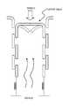
- FIG. 1shows a representative resistive profile through a hollow tubular body.
- FIG. 2shows a representative resistive profile through a hollow tubular body having a fixed resistor.
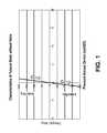
- FIG. 3shows a representative resistive profile for a simple differential resistor device.
- FIG. 4shows representative resistive profiles for differential resistors with a threshold for opening.
- FIG. 5shows another representative resistive profile for a differential resistor with a threshold for opening.
- FIG. 6shows a representative resistive profile for a differential resistor with a threshold for opening and a threshold for closing.
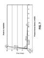
- FIG. 7shows another example of a representative resistive profile for a differential resistor with a threshold for opening and a threshold for closing.
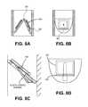
- FIGS. 8A and 8Bshow side views through a portion of one variation of a respiratory device having nested flap valves.
- FIG. 8Cshows a cross-section view through the valve show in FIG. 8A .
- FIG. 8Dshows a detailed view of the flap valve shown in FIGS. 8A-8C .
- FIGS. 9A to 9Cillustrate the operation of a door-within-a-door valve as described herein.
- FIGS. 10A to 10Cschematically illustrate different bias placement in a flap valve for use with the PEEP configured devices described herein.
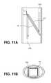
- FIG. 11Ashows a cross-sectional view of a door-within-a-door valve.
- FIG. 11Bshows a top view of the valve of FIG. 11A .
- FIGS. 12A-12Cshow top, side cross-section and bottom views of a valve having a living hinge as described herein.
- FIGS. 12D-12Fshow top, side cross-section and bottom views of another airflow resistor having a living hinge, similar to the valve shown in FIGS. 12A-12C .
- FIGS. 13A and 13Bshow perspective and cross-sectional views of a region of a respiratory device having two passageways.
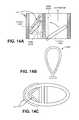
- FIG. 14Ashows a cross-sectional view of a region of a respiratory device having two passageways, as described.
- FIG. 14Bshows an elastomeric component of the respiratory device shown in FIG. 14A .
- FIG. 14Cshows a top view of the respiratory device shown in FIG. 14A
- FIGS. 15A to 15Cshow different variations of an anchored bias that may be used with an expiratory flap valve as shown in FIGS. 14A-14C .
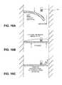
- FIGS. 16A to 16Cillustrate the operation of one variation of a device configured for PEEP.
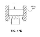
- FIGS. 17A to 17Dillustrate the operation of a respiratory device configured for PEEP.
- FIG. 17Eshows a profile of the device illustrated in FIG. 17A-17D within a nasal cavity.
- FIGS. 18A to 18Cillustrate the operation of nested flap valve.
- FIGS. 19A and 19Billustrate different variations of a flap valve having additional cutout valves.
- FIGS. 20A and 20Billustrate the operation of a rigid plate valve.
- FIG. 20Cshows a flap valve compatible for use with a plate valve.
- FIG. 20Dshows a hybrid rigid plate and flap valve configured for use with a PEEP device, as described herein.
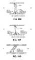
- FIGS. 20E to 20Gillustrate different variations of a hybrid rigid and flap valve similar to the valve shown in FIG. 20D .
- FIG. 21Ashows a flap valve configured to have a pressure profile as shown in FIG. 3 .
- FIG. 21Bshows another flap valve configured to have a pressure profile as shown in FIG. 3 .
- FIG. 22shows another variation of a PEEP device having a resistance profile similar to that in FIG. 5 .
- FIG. 23A and 23Billustrate a portion of a valve having a path accommodating surface that helps to regulate the resistance profile of the valve similar to that in FIG. 5 .
- FIG. 24illustrates another variation of a valve that may be included as part of a two or more passageway PEEP device.
- FIG. 24Billustrates another variation of the valve shown in FIGS. 24A and 24B .
- FIG. 25shows a respiratory device combining airflow through both nostrils, as described herein.
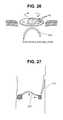
- FIG. 26shows another variation of an airflow resistor for use with any of the devices described herein.
- FIG. 27shows another variation of an airflow resistor for use with any of the devices described herein.
- FIG. 28shows a variation of an airflow resistor having an expandable wall for use with any of the devices described herein.
- FIG. 29shows a variation of an airflow resistor having a rolling hinge for use with any of the devices described herein.
- FIG. 30shows a variation of an airflow resistor having an inflatable flap for use with any of the devices described herein.
- FIG. 31shows another variation of an airflow resistor for use with any of the devices described herein.
- FIG. 32shows a variation of an airflow resistor having ball valve and a slider, for use with any of the devices described herein.
- FIGS. 33A to 33Dillustrate the operation of a bistable valve.
- FIG. 34illustrates one method of making a bistable valve, as described herein.
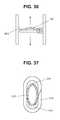
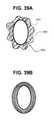
- FIG. 35shows a variation of a valve for use with any of the devices described herein.
- FIG. 36shows another variation of an airflow resistor for use with any of the devices described herein.
- FIG. 37shows a cross-section through the holdfast of a device as described herein.
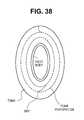
- FIG. 38shows one variation of an adjustable holdfast, as described herein.
- FIGS. 39A and 39Bshow cross-sections through a holdfast of a device configured for use within a subject's nose.
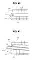
- FIG. 40shows one variation of an oral device including mandible displacement, as described herein.
- FIG. 41shows another example of an oral device as described herein.
- Described hereare respiratory devices, kits, and methods for their use in improving respiratory and cardiovascular function.
- respiratory devices for creating positive end expiratory pressure during respiration (PEEP) effect in a subject wearing the deviceare described. These respiratory devices are referred to as respiratory devices or simply as “devices.”
- the devices and methods described hereinmay be useful to treat a variety of medical disease states, and may also be useful for non-therapeutic purposes.
- the devices and methods described hereinare not limited to the particular embodiments described. Variations of the particular embodiments described may be made and still fall within the scope of the appended claims. It is also to be understood that the examples and particular embodiments described are not intended to be limiting.
- the devices for achieving PEEP described hereintypically include: one or more passageways through which air may pass to enter or exit a respiratory orifice; a holdfast for securing the device to, at least partially over, and/or at least partially within a subject's respiratory orifice; and an airflow resistor, or airflow resistors, for regulating the passage of air through the passageway(s) to achieve PEEP.
- these devicestypically do not require the application of an external pressure (e.g., from a continuous pressure source such as a pump), but operate only upon pressure generated by the subject wearing the device.
- these devices and methods for using themmay be easy to use, and may be removable and insertable by user without special tools.
- the devicesare typically reliable, and may be small and inexpensive to manufacture.
- a device configured as a PEEP deviceoffers only minimal resistance to inhalation, but has a very high resistance during low pressure exhalation up to a threshold pressure, and a lower resistance to exhalation above that threshold pressure.
- the devices for achieving PEEP described hereinmay have a characteristic resistance profile.
- the resistance profile of a devicerefers to the relationship between pressure across the device, and flow of air through the device.
- the resistance profile of a deviceis influenced by the shape and size of the passage(s) through the device, but it may be primarily influenced by the operation of the airflow resistor (or airflow resistors).
- an airflow resistormay include one or more valve or valves.
- an airflow resistormay be referred to as a valve for simplicity.
- the airflow resistorsmay include additional components in addition to the valve, and may also include multiple valves as part of a single airflow resistor.
- an airflow resistormay be referred to as a valve.
- a nasal respiratory device including an airflow resistorhas a resistance profile to expiration and inspiration.
- FIG. 1shows a typical resistance profile for a tubular body (e.g., a passageway) without a valve present.
- the x-axis of a resistance profileshows the pressure across the device (in cm of H 2 O). Pressure may also be represented as the pressure difference between the subject's respiratory system (e.g., oral cavity, nasal cavity, upper respiratory tract, etc.) and the external atmosphere (atmosphere).
- the y-axisshows the flow through the device (ml/sec).
- the devices described by these resistance profilesare assumed to be oriented so that inspiration results in negative flow (e.g., from the proximal to the distal end of the device) and expiration results in flow in the positive direction (e.g., from the distal to the proximal end of the device).
- inspirationor inhalation
- expirationor exhalation
- the orientation of the devicemay be switched so that the relative inspiratory and expiratory resistances may be reversed.
- the resistance of the deviceis a function of flow/pressure, as indicated by FIGS. 1-7 .
- this resistanceis often referred to as the resistance of the valve.
- the pressureis expressed as pressure in cm of H 2 O (or “cm H 2 O”).
- a positive pressureoccurs when the pressure on the side of the device fluidly connected with the inside of a subject's respiratory tract (e.g., within the nasal or oral cavity) is greater than the atmospheric pressure.
- a negative pressureoccurs when the subject's respiratory tract pressure (e.g., intranasal or intraoral pressure) is below atmospheric pressure.
- the resistance profilesillustrate pressure-flow characteristics showing linear behaviors (e.g., constant slopes).
- the resistance through the passageway of the deviceis constant, shown as a straight line passing through the origin.
- the pressure-flow profile for a tubular member without a valve (or other airflow resistor)has a steep slope across both inhalation and exhalation. The slope would be infinite (e.g., vertical) showing zero resistance to flow, but because there is a finite passage size for air passage, there will always be some discernable resistance.
- FIG. 2shows the effect of a simple airflow resistor within the passageway.
- a fixed resistorsuch a hole that limits the size of the passageway changes the resistance, which is reflected by a decrease in the slope from the unblocked condition shown in FIG. 1 .
- the slopehas decreased (reflecting an increase in resistance) over both inhalation and exhalation, since airflow is equally impeded in either direction.
- the resistanceis constant over the range of pressures shown for inhalation and exhalation.
- increasing or decreasing pressure across the deviceshown by the open arrows
- FIG. 3shows a resistance profile for a device having a simple “differential resistance” airflow resistor.
- a differential resistance devicehas a different resistance to airflow through the device at different parts of the respiratory cycle.
- a simple differential resistance deviceis a particular type of differential resistive device. In general, a simple differential resistive device has a substantially constant, low resistance to airflow during inhalation, and a substantially constant but higher resistance to airflow during expiration.
- FIG. 3shows a resistance profile for one example of a simple differential resistance device.
- This devicehas a low (but constant) resistance for inhalation, as shown by the steep linear slope during negative pressures, and a higher (but constant) resistance during exhalation, as shown by the flatter linear slope during positive pressures. Respiration through this device switches from inhalation to exhalation at the zero pressure point.
- Simple differential resistance valvesare described in detail in U.S. patent application Ser. No. 11/298,640, filed Dec. 8, 2005, herein incorporated by reference in its entirety.
- Exemplary respiratory devicesinclude simple flap valves (having one or more flaps); hingeless valves; stopper-type valves; membrane-type valves; ball valves; balloon-type valves; duck-bill valves, umbrella valves, and the like, in which the valve is open during inhalation, but closed (or at least partially closed) during exhalation, and may include one or more leak passageways through which air may pass.
- differential resistance devicesmay have different resistance profiles.
- a respiratory devicemay have different resistances at different pressures during expiration.
- FIG. 4shows a device having a resistance profile in which there is a threshold pressure for opening during expiration.
- the inhalational pressure(negative pressures) can be assumed to be a constant low pressure, as shown in FIG. 5 .
- the resistance of the device at low expiratory pressures across the devicee.g., between 0 cm of H 2 O and 10 cm of H 2 O
- the resistancedecreases to a constant level.
- Three different casesshown by the three different lines, A, B and C
- the threshold pressure for openingis 10 cm of H 2 O.
- a predetermined pressure threshold for openingfor opening the device
- the devicee.g., a valve within the device
- the deviceopens, allowing air to flow through it.
- this threshold valuee.g., you can have many different pressure-flow relationships above this threshold value, as seen by lines A, B and C.
- line Arepresents a lower resistance device
- line Brepresents a moderate resistance device
- line Crepresents a higher resistance device. In any of these devices, it does not matter whether the pressure is increasing or decreasing, as the flow will match the pressure differential for any pressure across the device.
- FIG. 5shows another example of a differential resistance device having a threshold for opening during expiration.
- a device having the resistance profile shown in FIG. 5may be ideal for PEEP.
- the deviceDuring inhalation (at negative pressure across the device), the device has a very low resistance (e.g., the airflow resistor may be substantially open during inhalation).
- the airflow resistorDuring exhalation at low pressures (e.g., between zero and the threshold for opening of 10 cm of H 2 O ) there is no flow. For example, the airflow resistor is closed. Above the threshold for opening, the resistance again drops, because air may flow through the airflow resistor.
- Differential resistance devices having resistance profiles such as those shown in FIG. 5may be useful as PEEP devices because they may help maintain positive end expiratory pressure within the subject's respiratory tract. For example, near the end of the expiratory portion of a respiratory cycle the pressure by which air is expelled may decrease as expiration ends. Thus, a subject expiring through a differential resistance device having a threshold for opening such as the one shown in FIG. 5 may be prevented from completely expelling air during expiration, resulting in a positive end expiratory pressure.
- a respiration device configured as a PEEP devicehas a threshold for opening of less than about 15 cm H 2 O, less than about 12 cm H 2 O, less than about 10 cm H 2 O, less than about 8 cm H 2 O, less than about 4 cm H 2 O, etc.
- the threshold for openingmay be between about 1 cm H 2 O and about 15 cm H 2 O, or between about 1 cm H 2 O and about 10 cm H 2 O.
- Exemplary devices having resistance profiles similar to those shown in FIG. 5are described more fully below, in the section titled “Exemplary Devices.”
- these devicesmay include an airflow resistor that is configured to be open during inhalation, and is closed at low pressure during exhalation, but at some threshold for opening, the airflow resistor opens to allow flow.
- the airflow resistormay be biased in the direction of expiratory flow so that the pressure across the airflow resistor must exceed some threshold amount before it opens.
- the airflow resistoris a bistable valve, which changes from a first stable configuration (e.g., closed during low-pressure expiration) to a second stable configuration (e.g., open during high-pressure expiration) when the pressure across the device reaches the threshold pressure.
- the transition from open during high-pressure operation to closed during low-pressure operationdoes not occur at the same threshold pressure.
- These devicesmay have a resistance profile similar to that shown in FIG. 6 .
- FIG. 6shows a differential resistance device with a threshold for opening and a threshold release during expiration. This means that during expiration, at low pressure the device is closed, but when the pressure across the device reaches a first threshold (the threshold for opening) the valve in the device opens to allow airflow. However, this open valve does not close until the pressure across the device reaches a second threshold (a threshold pressure for closing).
- a first thresholdthe threshold for opening
- a second thresholda threshold pressure for closing
- the expiratory portion of the resistance profileis shown in FIG. 6 .
- the deviceAt low expiratory pressures across the device (e.g., between zero and the threshold for opening shown here as 10 cm of H 2 O ) the device is effectively closed, preventing any airflow across the device (e.g., having an infinite resistance).
- the airflow resistorWhen the airflow resistor is closed, but the pressure across the device exceeds the threshold for opening, the airflow resistor will open, allowing airflow with a low resistance.
- the airflow resistordoes not re-close (e.g., reset) when the pressure across the device falls below the threshold for opening. Instead, the pressure must fall below a threshold for closing during expiration. In FIG. 6 , this threshold for closing is approximately 4 cm of H 2 O.
- the threshold for closingis the pressure at which the device is ‘reset’ back into the closed during expiration mode from the open during expiration mode. Once the device has closed, and flow has substantially stopped, the device will remain closed during expiration until the threshold for opening (e.g., 10 cm of H 2 O ) is again exceeded.
- the threshold for openinge.g. 10 cm of H 2 O
- the resistance profile shown in FIG. 5may be thought of as a special case of the situation described above for FIG. 6 , in which the threshold pressure to return the airflow resistor closed during expiration is the same as the threshold pressure required to open the airflow resistor during expiration.
- resistance profiles similar to the one shown in FIG. 6may be demonstrated by devices having bistable valves which change from a first stable configuration (e.g., closed during low-pressure expiration) to a second stable configuration (e.g., open during high-pressure expiration) when the pressure across the device reaches the threshold pressure.
- a first stable configuratione.g., closed during low-pressure expiration
- a second stable configuratione.g., open during high-pressure expiration
- FIG. 7shows another variation of a differential resistance device with a threshold for opening and a threshold for release during expiration.
- the threshold for releasee.g., closing the airflow resistor
- the devicedoesn't “reset” closed during expiration until after the inspiration occurs.
- Devices having resistance profiles similar to those shown in FIG. 6may also be useful as PEEP devices.
- devices in which the threshold pressure to return the airflow resistor to a closed state during expiration is greater than some minimum levele.g., greater than 1 cm H 2 O, greater than 2 cm H 2 O, greater than 3 cm H 2 O, greater than 4 cm H 2 O, greater than 5 cm H 2 O, etc.
- some minimum levele.g., greater than 1 cm H 2 O, greater than 2 cm H 2 O, greater than 3 cm H 2 O, greater than 4 cm H 2 O, greater than 5 cm H 2 O, etc.
- the threshold pressure for closingmay be any appropriate pressure values, particularly pressures in the range of: between about 0.5 cm H 2 O and about 15 cm H 2 O, between about 1 cm H 2 O and about 10 cm H 2 O, etc.
- the resistance profiles described aboveare idealized profiles.
- the pressure-flow characteristicsmay be non-linear, and may be curved or have other non-straight lines.
- the profiles shown hereillustrate general characteristics of resistance profiles.
- FIGS. 5 to 7show resistance profiles having flat regions (of infinite or very high resistance) when a valve is ‘closed’ during expiration, the valve may include one or more leak pathways through which air may pass.
- devices corresponding to the resistance profiles shown in the figurese.g., FIGS. 5 and 6
- the profiles described aboveare time-independent, and thus do not accurately reflect the time dependence of any of the devices described herein.
- the time response of the respiratory devicemay also affect the operation of the device. For example, it may be desirable to delay the response of the change in resistance based on the time point of the respiratory cycle. For example, it may be beneficial for a PEEP device to delay closing the valve after switching from inhalation to exhalation, even though the respiratory pressure is relatively low across the valve.
- the respiratory devices described hereinalter airflow into and out of the lungs through a respiratory cavity such as the mouth and/or the nostrils of the nose in order to achieve positive end-expiratory pressure (PEEP).
- These respiratory devicestypically include one or more passages, a holdfast for securing the device in communication with a subject's respiratory cavity, and an airflow resistor (e.g., valve) capable of obstructing airflow with high resistance during low-pressure expiration, and opening to allow substantial airflow during high-pressure expiration.
- the respiratory devicesmay include an airflow resistor having a threshold pressure during expiration for opening the airflow resistor to allow airflow when the threshold pressure is exceeded.
- the airflow resistoralso has a threshold for closing during expiration, below which the airflow resistor inhibits expiratory airflow until the threshold pressure for opening is again exceeded. Specific examples of devices having appropriate airflow resistors are described below.
- any of the devices described hereinmay be specifically adapted for nasal use.
- these devicesmay be considered nasal respiratory devices.
- the devicesmay include a holdfast for securing the passageway(s) in communication with the nasal cavity to regulate airflow through the nasal cavity.
- the holdfastmay secure the device at least partially over and/or at least partially across the nose (particularly in contact with the area around the nasal opening).
- the holdfastsecures the device at least partly within the nasal cavity.
- Nasal devices described hereinmay be configured so that they do not cover the subject's mouth, and therefore the subject may be free to breathe through the oral cavity without additional resistance.
- the respiratory devices described hereingenerally comprise an airflow passageway and an airflow resistor.
- the airflow passageway(or “passageway”) generally defines a channel allowing the passage of air.
- the passagewaymay be of any suitable size or shape; however it is configured so that when the respiratory device is worn by a patient, the passageway comprises an opening leading toward the patient's lungs in fluid connection with an opening that leads away from the patient's lungs.
- the terms “patient” and “subject”are used to describe any user of the respiratory device, including users who are not using the respiratory device for therapeutic purposes.
- the airflow passagewaymay be any suitable length.
- the passagewaymay be as short as the airflow resistor will allow (e.g., extending only far enough to communicate with the airflow resistor).
- the airflow passagewaymay be longer than the space required to support the airflow resistor.
- the airflow passagewaymay be approximately as long as the length of an average nare. In some versions, the passageway extends the length of an average nasal chamber.
- the neutral cross-sectional area of the passagewaymay be of any appropriate size.
- Neutral cross-sectional areamay refer to the cross-sectional area of the passageway when the device allows air to flow through the passageway without additional resistance (e.g., from the airflow resistor).
- the size (e.g., diameter) or shape of the passagewaymay depend upon configuration of the respiratory device.
- respiratory devices configured to be inserted within the nasal cavitye.g., a nasal chamber
- Respiratory devices configured to be secured over an oral cavity or a nasal cavitymay have passageways of larger diameters.
- the cross-sectional area of a passagewaymay vary along the length of the device.
- the airflow passagewaymay comprise a dedicated structure defining the inner wall of the airflow passageway, or it may be a structural component of the device.
- the passagewaymay comprise a passage wall defined by a rim.
- a rimmay be a tube (or tunnel) of material of any appropriate thickness.
- the rimmay also be a frame, rather than a complete tube.
- the rimmay comprise a sufficiently rigid material so that it can support the passageway, and prevent the passageway from collapsing during use and during respiration.
- at least a portion of the rimis made of a compressible material that may be compressed to facilitate insertion and removal, while maintaining the ability to support the passageway and prevent complete collapse of the passageway during respiration.
- the rimmay also be somewhat compressible during respiratory flow.
- the airflow passageway(including a rim portion) may also serve as an attachment site for other components such as airflow resistors, filters, anchors, etc.
- the rimmay be any suitable shape or size.
- the rimmay comprise a ring shape or an oval shape.
- the rimmay define the inner diameter of the passageway.
- the rimcomprises a material having strength sufficient to prevent the collapse of a respiratory device that has been inserted into a nasal cavity.
- the rimmay comprise a metal, a polymer (particularly stiff polymers), etc.
- the rimmay comprise softer or “weaker” materials which are formed or arranged so that the final shape of the rim has sufficient strength to prevent the collapse of the respiratory device during use.
- a respiratory devicemay include a rim that is a tube or tubular body having a distal end and a proximal end, through which the airflow passageway extends.
- the distal end of the respiratory deviceis inserted first into the subject's nose, so that the device is worn so that during inhalation air flows from the proximal to the distal end of the passageway, and during expiration air flows from the distal to proximal end of the passageway.
- the proximal end of the tubular bodyhas different properties from the distal end. For example, the thickness of the tubular body from distal end to proximal end may vary.
- the respiratory devicehas a tubular body in which the distal end is more compliant than the proximal end.
- the distal endmay be more readily compressed for insertion into the nasal cavity, while the proximal end is somewhat more rigid, allowing for easier removal/insertion of the device.
- a more compliant distal endmay also help the device better fit a subject wearing the device, and may enhance comfort.
- the distal region of the devicemay conform to fit the nasal cavity.
- the distal endis more compliant than the proximal end because different regions of the tubular body are made from different materials or have different structures.
- a distal portion of the tubular bodymay have a wall thickness that is less than the wall thickness of the more proximal portion of the tubular body.
- the rime.g., tubular body
- the wall thicknessmay be uniform for a given distal-to-proximal position (e.g., along the length of a respiratory device's tubular body).
- the wall thickness of the tubular body (rim)may be zero in some regions, meaning that the tubular body includes holes or windows, or comprises a frame.
- Regions of different wall thicknessmay result in different regions of the airflow passageway having different diameters or cross-sectional shapes.
- the respiratory devicehas a tubular body having a proximal wall thickness that is greater than the distal wall thickness
- the region where the thicker proximal wall thickness meets the thinner distal wall thicknessmay form a step or ledge along the wall of the passageway.
- the outer diameter (OD) of the tubular bodyis uniform while the inner diameter (ID) has at least two different measures.
- this ledge or step within the passagewaymay form a valve seal surface by providing a surface on which a valve (e.g., a flap valve) may abut or lie against when in the closed position.
- a valvee.g., a flap valve
- the tubular bodymay have any appropriate cross-sectional area.
- a rim configured as a tubular bodymay have an elliptical cross-section through its length that is shaped similarly to that of most patients' nares. This shape may help maximize the cross-sectional size of the passage while maintaining comfort.
- the passagewaymay also comprise other cross-sectional shapes, such as circular, polygonal, teardrop, or other asymmetric shapes.
- the respiratory devicedoes not include a separate rim forming the passageway.
- the airflow passageway of the respiratory devicemay be a passageway through a holdfast.
- the devices described hereinmay include more than one passageway.
- many of the illustrations of devices provided hereinare for nasal devices (e.g., devices for use in a nasal cavity), it is to be understood that these devices may be adapted for use with any respiratory orifice (e.g., mouth, nose, etc.).
- Airflow resistors for use with the PEEP devices described hereinare typically positioned in communication with an airflow passageway, so that at least some (if not all) of the air flowing through the passageway passes the airflow resistor.
- an airflow resistormodulates, alters, varies, or keeps constant the amount of resistance, the degree of airflow, or the pressure differential across the device or through a passageway in the device.
- a typical PEEP airflow resistorhas very little resistance to inhalation, has a high resistance to expiratory airflow at low expiratory pressures, and has a threshold pressure for opening, above which the airflow resistor has a relatively low resistance to expiration.
- the airflow resistore.g., a valve
- the airflow resistorhas a threshold pressure for closing during exhalation, so that if the pressure across the valve during expiration falls below the threshold for closing, the airflow resistor will close, resulting in a high resistance to flow.
- the flap regionmay include a stiff or flexible material, or some combination thereof.
- the flap valveincludes a stiff region of the valve, which may help give the flap support.
- the flapcomprises a polymeric material, as described below.
- the flap valvemay be biased (e.g., in an open or a closed position) or it may be unbiased.
- a bias elementsuch as a spring may be used, or the flap may be made of a material that has elastomeric properties that bias the valve in a particular position.
- a biased valveis a valve that tends to remain in a particular position (e.g., flat, bent, open, closed, etc.) when at rest, and changes position (e.g., from closed to open) after an appropriate force is applied to the device to overcome the bias.
- the biasmay be provided by a biasing element (e.g., spring, tether, weight, or the like), or a material property of the valve (e.g., the stiffness).
- the airflow resistormay also be used with additional components.
- respiratory devicesmay include an airflow resistor seal surface (valve seal surface), an airflow resistor support (valve support), and/or an airflow resistor aligner (valve aligner). Examples of these features are provided in more detail in U.S. Patent Application titled “NASAL RESPIRATORY DEVICE,” filed May 22, 2007 by inventors Rajiv Doshi, Bryan Loomas, and Ryan Kendall Pierce, the entirety of which is herein incorporated by reference in its entirety.
- the airflow resistor or valvemay be any appropriate shape, particularly shapes in which the passageway may be blocked or at least partly occluded.
- the respiratory devicemay also include one or more leak paths.
- a leak pathallows air to flow through or past the respiratory device even when the airflow resistor is closed.
- a leak pathmay be included as part of any portion of the device, including the holdfast, the rim (e.g., the tubular body), or the airflow resistor.
- the sizes, locations and distributions of the leak path(s)may be chosen to permit a desired amount of airflow through the device at a known pressure and/or flow rate.
- the leak pathmay be incorporated as part of an airflow resistor.
- the leak pathmay be one or more holes or channels through the valve, even when the valve is closed. In some variations, the leak path is not included as part of the valve.
- the PEEP respiratory devicemay further comprise a holdfast for releasably securing the device in communication with a nasal cavity.
- the holdfastmay facilitate the positioning and securing of the device in a desired location, such as over or within (e.g., substantially within) a nasal orifice.
- the holdfastmay allow the device to be anchored, positioned, and/or stabilized in any location that is subject to respiratory airflow such as a nasal cavity.
- Nasal cavitiesmay include the following anatomical structures, or conduits defined by the following anatomical structures: the nostrils, nares or nasal chambers, limen, vestibule, greater alar cartilage, alar fibrofatty tissue, lateral nasal cartilage, agger nasi, floor of the nasal cavity, turbinates, sinuses (frontal, ethmoid, sphenoid, and maxillary), and nasal septum.
- the term “nasal cavity”may refer to any sub-region of the Nasal Fossa (e.g., a single nostril, nare, or nasal chamber).
- the holdfastmay also secure a seal between the respiratory device and the respiratory airway, so that at least some of the air exchanged between the outside of the patient and the respiratory airway must pass through the respiratory device.
- the holdfastseals the device in communication with a respiratory cavity completely, so that all air must be exchanged through the device.
- the holdfast sealis incomplete, so that only some of the air exchanged between the patient and the external environment passes through the device.
- airmay be air from the environment external to the patient, or it may be any respiratory gas (e.g., pure or mixed oxygen, CO 2 , heliox, or other gas mixtures provided to the user).
- the holdfastmay comprise an anchor or anchor region.
- the deviceis to be placed by the patient or the healthcare provider in or around the nasal cavity.
- Holdfasts appropriate for nasal cavitiesmay secure the device in position within a nasal cavity (e.g., through one or both nostrils) or against surrounding structures.
- the holdfastmay comprise a shape, surface or material that secures the device in communication with a nasal cavity.
- the holdfastmay comprise a cylindrical shape that allows the device to fit securely or snugly within a nostril.
- the outer surface of the devicemay comprise a holdfast including an adhesive material.
- the holdfastmay also partially or completely seal the device in communication with the nasal cavity.
- the holdfastmay comprise insertive and/or non-insertive mechanisms.
- the holdfastcomprises a mechanical connection between the device and the user, such as clips, straps, and the like.
- the holdfastmay be formed from a soft or compliant material that provides a seal, and may enhance patient comfort. Furthermore, compliant materials may reduce the likelihood that the device cuts off blood flow to the part of the respiratory cavity and surrounding regions to which the device is anchored.
- This compliant materialmay be one of a variety of materials including, but not limited to, plastic, polymers, cloth, foamed, spongy, viscoelastic, and/or shape memory materials. Shape materials include any that have a preferred conformation, and after being deformed or otherwise deflected or altered in shape, have tendency to return to a preferred conformation.
- Soft shape memory materialsmay include, but are not limited to, urethane, polyurethane, sponge, and others (including “foamed” versions of these materials).
- the holdfastmay not be soft or compliant and may instead be a rigid structure that interfaces directly with the respiratory orifice.
- the devicemay fit completely within a nostril (or both nostrils), or may project out of the nostril, depending on the particular embodiment.
- the devicemay be placed high enough within the nasal cavity so that it cannot be seen within the nostril.
- the devicemay be located completely outside of the nose, for example, in some versions the holdfast has a shape that conforms to the outside surface of the nose.
- the holdfastmay comprise one or more straps, bands, or the like to ensure an adequate fit and/or seal maintaining the device in communication with the nasal cavity.
- the holdfastmay comprise one or more projections that are inserted within the nostrils.
- a devicemay be placed at least partly in both nostrils, and may comprise a bifurcated passageway or two passageways that the holdfast places in communication with the nasal cavity through each nostril.
- the inspiratory and/or expiratory airflow to and from the lungsmay be regulated through each nostril separately or together.
- separate devicesmay be placed at least partly in each nostril, and may be connected to each other and/or to the patient using a clip, tether, strap, band, chain, string, or the like.
- connection meansmay connect one rim from one device to a rim from a second device or a holdfast from one device to a holdfast from a second device, or some combination thereof. Any portion of one device may be connected by said connection means to any portion of the second device.
- the connection meansmay comprise a shape memory material. Such a system would facilitate subsequent removal of the device and make migration of the devices deeper into the nasal cavity less likely.
- an adhesive regionmay be present to help attach the device to the inside or outside of the nose (including the nostrils), to the oral cavity, to the neck, or to the face. The use of an adhesive or any other means may prevent the inadvertent or otherwise undesired removal of the subject devices during sleep.
- the holdfast portion of a respiratory devicemay also be shaped to fit within the subject's anatomy to secure the device in place and/or to prevent leakage of airflow around the device.
- the holdfastmay be shaped to fit within the widening of the nasal cavity immediately inside the nares (opening of the nostril).
- the holdfastmay conform to the walls of a portion of the nasal cavity both to hold the device within the nose, and also to prevent substantial leak of air around the device when worn in the nose.
- Materials such as foamse.g., foamed polyurethane
- foamed polyurethanemay be particularly useful for this purpose, since these materials may be readily compressed for insertion and rapidly expand within the nasal cavity to secure the device in place.
- a holdfastmay be attached to a respiratory device.
- a holdfastmay be attached to a rim.
- the holdfastis connected to the outer surface of the tubular body.
- a holdfastmay be glued, taped, stitched, welded, or otherwise connected to the rim of a respiration device.
- the holdfastcircumferentially surrounds at least a portion of a rim.
- the distal end of the tubular body (e.g., rim) of the deviceis ensheathed by a holdfast of foamed material.
- the holdfast thicknessis substantially uniform along most or all of the periphery of the device.
- the holdfast thicknessmay be either symmetrically or asymmetrically distributed.
- the height and length of the foam forming a holdfastmay also be uniform or non-uniform, symmetrically or asymmetrically distributed.
- a holdfastmay be thicker in some regions than in other regions.
- the cross-sectional profile of the holdfaste.g., the profile though the long axis of a respiratory device including a holdfast
- the holdfast in communication with the tubular bodyis thicker near the long axis of the elliptical profile of the tubular body than at the short axis of the tubular body.
- the thickness of the holdfast around the profile of the tubular body cross-sectionis related to the diameter of the passageway through the device.
- the thickness of the holdfast at any point outside of the passagewaymay be between about 0.2 times and about 2 times the distance from the center of the passageway to the outer edge of the tubular body around the radius of the passageway.
- the holdfastmay be between about 0.8 mm and about 8 mm thick at the long axis of the elliptical cross-section of the tubular body, and between about 0.4 mm and about 4 mm thick at the short axis of the elliptical cross-section of the tubular body.
- the devicemay be removably secured by a holdfast, meaning that the device may be inserted into the subject's nasal cavity for some amount of time, and then removed.
- a removable holdfastexerts sufficient pressure on the nostril walls (e.g., within the nasal cavity) to hold the device in position without harming the subject, or producing too much discomfort.
- the devicemay be used continuously for an appropriate time period (e.g., overnight, such as 6-8 hours).
- the holdfastdoes not generally need to be secured more permanently.
- the holdfast material properties and shapetypically lend themselves to easy, fast, and pain-free insertion and removal.
- the holdfastmay be a compressible/expandable foam material.
- the shape and size of the holdfastmay also be chosen to appropriately secure the device within a subject's nasal cavity comfortably.
- the foammay have compression properties that allow it to be readily compressed (for insertion into the nasal cavity), but expand to fit the cavity quickly once inserted.
- the holdfastmay also have a thickness and width sufficient to fit snugly but comfortably within the subject's (including an ‘average’ subject or range of different subject sizes) nasal cavity.
- the foam thicknessis not uniform.
- the ends of the holdfast regioncomprise a foam that is thicker than in the middle, which may allow the device to fit noses which are longer and narrower.
- Respiratory devicesmay be made from any appropriate material or materials.
- the devicesinclude a shape memory element or elements, as part of the holdfast, in the airflow resistor, or in giving form to the passageway.
- Any convenient shape memory materialthat provides for flexibility and resumption of configuration following removal of applied force may be employed in these embodiments.
- shape memory alloysmay be used.
- a variety of shape memory alloysare known, including those described in U.S. Pat. Nos. 5,876,434; 5,797,920; 5,782,896; 5,763,979; 5,562,641; 5,459,544; 5,415,660; 5,092,781; 4,984,581; the disclosures of which are herein incorporated by reference in their entirety.
- the shape memory alloy that is employedshould generally be a biocompatible alloy.
- Biocompatible alloysmay include nickel-titanium (NiTi) shape memory alloys sold under the NitinolTM name by Memry Corporation (Brookfield, Conn.).
- NiTinickel-titanium
- spring steel and shape memory polymeric or plastic materialssuch as polypropylene, polyethylene, etc.
- Rubber and polymeric materialsmay also be used, particularly for the holdfast, rim, or airflow resistor.
- Injection moldable materialssuch as polyether block amide (e.g., PEBAX®), and the like may be used.
- Materials which may be usedinclude: latex, polyethylene, polypropylene, polystyrene, polyvinyl chloride, polyvinylidene chloride, polyvinyl acetate, polyacrylate, styrene-butadiene copolymer, chlorinated polyethylene, polyvinylidene fluoride, ethylene-vinyl acetate copolymer, ethylene-vinyl acetate-vinyl chloride-acrylate copolymer, ethylene-vinyl acetate-acrylate copolymer, ethylene-vinyl acetate-vinyl chloride copolymer, nylon, acrylonitrile-butadiene copolymer, polyacrylonitrile, polyvinyl chloride, polychloropren
- Biocompatible materialsmay be used, particularly for those portions of the device (e.g., the holdfast) which may contact a user.
- the biocompatible materialsmay also include a biocompatible polymer and/or elastomer.
- Suitable biocompatible polymersmay include materials such as: a homopolymer and copolymers of vinyl acetate (such as ethylene vinyl acetate copolymer and polyvinylchloride copolymers), a homopolymer and copolymers of acrylates (such as polypropylene, polymethylmethacrylate, polyethylmethacrylate, polymethacrylate, ethylene glycol dimethacrylate, ethylene dimethacrylate and hydroxymethyl methacrylate, and the like), polyvinylpyrrolidone, 2-pyrrolidone, polyacrylonitrile butadiene, polyamides, fluoropolymers (such as polytetrafluoroethylene and polyvinyl fluoride), a homopoly
- PEEP devicescontain valve mechanisms that may be used to achieve PEEP, and therefore may be referred to as PEEP devices or PEEP valves. Many of these examples describe only airflow resistors or the valve components of an airflow resistor, however it should be understood that these airflow resistors or valves may be used as part of a respiratory device. It should also be understood that a single device may include more than one of these valves.
- valves described hereinmay be used as part of a PEEP device having a resistance profile similar to that of FIG. 5 (exemplifying a differential resistance devices with a threshold for opening during expiration), and FIG. 6 (exemplifying a differential resistance devices with a threshold for closing during expiration).
- differential resistance devices having a threshold for opening during expirationcomprise one or more valves that open (or open more fully) to reduce the resistance through the valve only after the pressure across the valve exceeds the threshold for opening.
- the threshold for openingis determined by a bias which must be overcome before the valve (or valves) can be opened.
- a biasmay be preloaded, so that the valve cannot be opened until the preloaded force is overcome.
- the threshold pressure for opening a valvemay be the preloaded force.
- nested flap valveshaving nested flaps, where the flaps open in opposite directions, as shown schematically in FIG. 18A-18C .
- nested flap valvesmay be used for PEEP devices when one of the flaps is biased so that it opens only after the pressure across the valve exceeds a threshold for opening.
- a nested flap valvemay be configured so that the resistance profile resembles the profile seen in FIG. 5 , for example.
- the generic nested flap valve shown in FIG. 18Ahas two flaps, a first flap and a second flap, that are each hinged.
- the first flapis opened during inhalation, so that air may flow from the top of the valve to the bottom of the valve. Relating this to the resistance curve shown in FIG. 5 , during inhalation (negative pressure), the first flap of the valve is easily opened, and has a very low resistance.
- FIG. 18Bshows the valve flap during exhalation. The positive pressure moves the first flap to close off the passageway (the passageway is not shown). At positive pressures (exhalation) below the threshold for opening the second flap, the first flap closes the passageway but the pressure across the valve is not sufficient to open the second valve.
- the second flapis biased so that it only opens when the pressure exceeds the threshold pressure for opening.
- Any appropriate biasmay be used.
- a biasapplies force to oppose the opening of the flap.
- the second flapmay be biased by a structural bias (e.g., a spring), an elastomeric material (or region of the valve), or a combination of these.
- the second flapmay be biased because of the material property of the hinge region or the flap itself.
- the flaps of a nested flap valvemay be oriented in any appropriate orientation.
- the flap valveis oriented so that both flaps are hinged in parallel.
- the hinges of the nested flapsmay be perpendicular, or parallel, or any appropriate angle.
- a living hingemay be used with any of the appropriate valves described herein, including flap valves.
- either the first or second flapmay be formed (e.g., cut, molded, etc.) from the same material.
- the valvemay include a living hinge and a region that deflects under pressure, allowing airflow.
- the size and shape of the opening formed by the deflectable material(as well as the shape and size of the living hinge) may determine the resistance to airflow through the valve.
- FIG. 19Aillustrates an examples of living hinges for a valve similar to the nested valve in FIGS. 18A-18C .
- FIG. 19Ashows four nested flaps 1901 cut into the body of the first flap 1903 .
- the flapalso includes holes 1907 (e.g., post holes) for mounting to one or more valve aligners.
- the nested flapsare shown as semi-circular cutout regions of the flap having a living hinge between the ends of the cutout region. These hinged flaps may allow airflow, and will open when pressure is applied. The amount of pressure required to open these flaps may be effected (or controlled) by the length of the hinge, the size (e.g., area) of the cutout region, the thickness and/or stiffness of the material, the effective moment arm (e.g., the distance from the flap hinge to the effective position of rotational force from the pressure), etc.
- the living hinge region(the region that is not cut out) may also be shaped by partially shaping or cutting the material forming the hinge region. For example, the hinge region may be undercut or thinned to make opening easier.
- FIG. 8Ashows another example of a device having nested flap valves.
- a first (“inspiratory”) pair of flap valves(hinged 801 together in the center of the passageway) open easily during inspiration, when pressure is greater from proximal region of the device, shown here towards the top of the device.
- a second (“expiratory”) pair of flap valves 803is located on each of the inspiratory flap, and hinged 805 to open during expiration, when pressure is greater from distal region of the device, shown here towards the bottom.
- the flap door of the second pair of flap valvesis biased using an elastic spring member, as shown in FIG. 8C in a cross-section though one of the pairs of nested valves.
- FIG. 8Dshows a side view of the surface of the inspiratory valve, showing the embedded expiratory valve thereon.
- the valve shown in FIG. 8A to 8Doperates as shown in FIG. 9A to 9C .
- the valveor pairs of valves
- the inspiratory flap valve(s)opens to allow airflow through the passageway relatively unobstructed.
- the valves in FIGS. 8 and 9are relatively stiff flap valves, so that the valves do not collapse during normal operation.
- the inspiratory flap valvecloses, and the force applied by the subject during expiration acts across the expiratory valve, which is biased by the elastic spring member (or any appropriate bias). If the pressure across the valve is greater then the force applied by the elastic spring member, then the expiratory valve opens, as shown in FIG. 9C .
- the force applied by the spring member in FIGS. 8A to 9Ccorresponds to the threshold pressure for opening.
- the threshold pressure for openingcan be adjusted or predetermined based on the bias element characteristics, including the attachment of the bias element (here, the spring member) to the valve.
- FIGS. 10A to 10Cillustrates the effect of bias position on the threshold pressure for opening.
- the valvestays closed until a predetermined pressure is reached across the valve (a threshold pressure for opening), and then the valve opens, allowing maximum outflow until the pressure decrease below the threshold.
- This variationcomprises a single flap valve that is in communication with the walls of the passageway, and is hinged or otherwise flexibly (movably) connected at one end.
- This valvemay be incorporated into a device such as the device shown in FIGS. 8A to 9D .
- FIG. 10Athe valve is shown in cross section as a stiff valve 1001 , connected to a bias 1003 (e.g., a spring, elastomeric material, etc.).
- a bias 1003e.g., a spring, elastomeric material, etc.
- the biasing force applied by the spring as the valve is openedis likely to decrease slightly as the valve leaf (flap) is deflected open by pressure across the valve.
- the placement of the biasmay affect the amount of force required to open the valve completely or partially.
- FIGS. 10B and 10Cshow arrangements of the bias element 1003 which may result in an almost constant force, adding little additional resistance to completely open the valve once initial pressure is exceeded.
- the placement of a biasing elementmay be chosen so that the threshold pressure required to fully open the valve remains constant, or increases as resistance through the device decreases (as the valve opens).
- FIGS. 11A and BAnother variation of a nested flap valve is shown in FIGS. 11A and B.
- the valveincludes an inspiratory door 1103 (flap) portion that opens during inspiration, and an expiratory door 1101 portion built into the inspiratory door, that may open during expiration.
- Both the inspiratory door and the expiratory doorare stiff members, and both are rectangular when viewed perpendicular to their faces, as shown in the top view of FIG. 11B .
- the passagewaymay be adapted to have a rectangular cross-section so that the valve can seat within the passageway and obstruct airflow through the passageway unless the doors are open.
- the dashed lines indicated by 1105show the open position of the valve during inspiration.
- both the upper and lower flap valvesopen and move together.
- only the nested expiratory dooropens when the expiratory pressure across the door is greater than the threshold for opening, as indicated by the dashed lines 1107 .
- FIG. 12shows another variation of the door-within-a-door type (e.g., nested) valve described in FIG. 11 .
- This variationmay be fabricated from an elastomeric material.
- the doors of the valveare hinged using a living hinge as described, where the hinge regions are cut into the hinge shape to allow flexion.
- FIG. 12Ashows a top view of the airflow resistor including this valve through the passageway.
- FIG. 12Bshows a cross-section through the side of the airflow resistor, and
- FIG. 12Cshows a bottom view from within the airflow resistor.
- An alternative top viewis shown in FIG. 12D , in which a sealing face or ledge 1201 is included for the door to seal or rest against.
- FIG. 12Eshows a cross-sectional view of the airflow resistor shown in FIG. 12D
- FIG. 12Fshows a bottom view of the same airflow resistor.
- FIGS. 20A to 20Dshow an example of a valve appropriate for an airflow resistor of a PEEP device in which a flap valve is combined with a rigid valve.
- a rigid valve 2001is biased against a valve seal region 2003 .
- the bias 2005is preloaded in compression so that it tends to hold the rigid valve against the valve seal.
- the preloaded compressive forceestablishes the threshold pressure for opening.
- FIG. 20Cshows a dual flap valve having two flaps covering two openings (holes). This flap valve is combined with the rigid and biased valve shown in FIGS. 20A and 20C to form a valve that may be configured to create PEEP, as shown in FIG. 20D .
- FIGS. 20E-20Gshow different variations of airflow resistors comprising valves that may be used as part of a PEEP device, similar to the biased flap valve shown in FIG. 20D .
- the rigid region of the valveis not biased at its center, but is instead biased so that it opens like a door (on one side).
- the rigid region of the valvealso includes two biases, a bias for compression as well as tension.
- the combination of different biasesmay be used to more accurately control the resistance profile of the valve, and in particular, may be used to set the threshold for opening during expiration (e.g., flow ‘out’ of the device, as indicated by the ‘in’ and ‘out’ directions).
- the flap valveis also shown as a side-hinged valve.
- a flap valverotates around a fixed point when force is applied at some distance from that point, causing deflection of the flap relative to the point and/or mechanical deformation of the flap.
- the moment armmay be increased (as shown in FIG. 20B ) by increasing the movable area of the flap.
- the length of the moment armmay also be increased by increasing the distance between the hinge and the opening through which the force is applied. This may be achieved, for example, by building the flap valve so that it sits at an angle with respect to the passageway.
- the PEEP devicemay comprise more than one passageway, in which each passageway includes a valve.
- one passagewayis used for inspiration, and one is used for expiration.
- FIG. 13Ashows a perspective view of a PEEP device having two passageways.
- a cross-sectional viewis shown in FIG. 13B .
- the inspiratory side of the deviceincludes a flap valve that readily opens during inspiration, but remains closed during expiration.
- the cross-sectional area of either passagewaymay be equal, or one of them may be bigger than the other (e.g., the expiratory passageway may be smaller than the inspiratory passageway).
- the expiratory sideincludes a biased valve (similar to the valves described above), which is set to open when the pressure across the device exceeds the threshold for opening.
- the bias 1301 shown in FIG. 13Bis schematically indicated.
- One embodiment of this biasincludes an elastomeric band (e.g., spring), as shown in FIGS. 14A-14D .
- the PEEP deviceincludes two chambers, as shown in the cross section shown in FIG. 14A .
- the elastomeric element 1401(shown in FIG. 14B ) is wrapped around the outside of the passageway after passing thorough holes on either side of the passageway to connect to the flap and bias it within the expiratory passageway. This is shown in FIG. 14C , in a top view of the closed expiratory valve.
- the elastomeric elementis attached by passing through a hole in the flap, where it anchors on the opposite side of the flap.
- FIGS. 15A , 15 B and 15 Cshow alternative ways to anchor the bias (e.g., a spring or elastomeric element) to the expiratory flap valve shown in FIG. 14A-14C .
- a springis anchored (e.g., via a hook) thorough a hole fabricated on the flap.
- the biasis a wire that passes through the flap and anchors beneath it.
- the biasconnects to a loop of wire that is pushed through a hole in the door (flap).
- FIGS. 24A and BAnther variation of a valve that may be included as part of a two or more passageway PEEP device is shown in FIGS. 24A and B.
- an elastomeric membrane 2401is positioned over only one end of a passageway 2409 , and other passageways may be substantially blocked off by an occlusive wall 2411 (for convenience, not shown in the additional FIGS. 24B to 24D ).
- the membrane 2401is positioned so that a threshold pressure (P T ) is required to displace the membrane from over an opening 2403 . Airflow is therefore blocked until the elastomeric membrane is deflected, as shown in FIG. 24B .
- P Tthreshold pressure
- FIGS. 24C and 24Dillustrate another variation of the valve shown in FIGS. 24A and 24B .
- FIG. 21Ashows one example of a valve that is not typically configured for PEEP, but that may be used in combination with a bias or with another valve to achieve PEEP.
- FIG. 21Ashows a flap valve that is hinged on one side, and is constrained from opening during expiration (e.g., into the page), by a crossbar. During inspiration, the valve bends (out of the page), permitting airflow. In some variations, the flap valve bends everywhere along the length of the valve (e.g., 0 ⁇ x ⁇ w). In other variations, bending during inspiration is focused on the area near the hinge (e.g., x approximately equal to w), and the flap may be reinforced elsewhere, or may comprise a more rigid material or greater thickness.
- the valvemay be relatively easily opened during inhalation because of the relatively large surface area of the flap, and the large moment arm.
- the valveis constrained for easily opening by the crossbar, however, since there is no “preload” (e.g., bias) on the distal region of the flap, it will simply open a little with a little pressure, and more with greater pressure, resulting in a pressure profile similar to the profile shown in FIG. 3 .
- the flapis stiff
- the crossbaris an elastomeric material. Thus, the crossbar yields during exhalation to open the valve.
- FIG. 21Billustrates another variation of a valve which may be used as part of a PEEP configured device.
- Two or more flapse.g., such as the flap shown above in FIG. 21A
- two flapsare hinged, and each valve is constrained from opening during exhalation by a crossbar, similar to FIG. 2A .
- the flapsare arranged in an overlapping saloon-door configuration, so that there is an overlapping region between the crossbars.
- the flapsmay open easily during inspiration, as described above for the variation shown in FIG. 21A .
- each flapfurthest from the hinge region
- the flapsmay be continuously flexible (so that they can bend everywhere along their length) or relatively stiff.
- a PEEP resistance profilemay result, since the two doors need to move a certain distance (providing a preload) before air can get by them.
- FIG. 22shows another variation of an airflow resistor including a valve that is configured to operate as part of a PEEP device having a resistance profile similar to that in FIG. 5 .
- the valveincludes a door 5 that is hinged 6 so that during inhalation, the door opens without much resistance (inhalation is airflow towards the distal direction, e.g., P 2 >P 1 ).
- stopper 1prevents the door 5 from rotating open beyond the set position. Further rotation of the door 5 in the direction of the exhalation (e.g., the proximal direction), requires bending around a hinge region 2 that is part of the door.
- This second hinge region 2may resist bending because of material stiffness of the door, and/or contact between the door and the surface of the passageway region opposite of the door 4 .
- the surface of the passageway opposite the door 4 in the proximal direction of the passageway(e.g., in the proximal direction) may be configured to prevent opening of the valve during exhalation as the door bends in the distal direction.
- the surface of the passage 4is curved to prevent airflow during exhalation until the pressure across the valve (the pressure differential P 1 ⁇ P 2 ) is large enough to push the end of the door 5 past the curvature of the wall 7 at the end of the curved surface 4 .
- the pressure differential P 1 ⁇ P 2the pressure differential
- the dooris augmented with a support 3 that stiffens it so that the door does not readily bend in this region.
- the support 3may therefore help localize bending to the hinge regions, which may help prevent flow thorough the device until the door has passed the end of the shaped region of the passageway 4 .
- the threshold for opening during expiration for this devicemay therefore be controlled by the flexibility of the second hinge region 2 , the surface area of the door 5 , and the geometry of the shaped region of the passageway 4 .
- the shaped regionis a path-accommodating surface that may interact with the flap or door of the valve.
- the valveis biased in the exhalation direction (P 1 >P 2 ) by the stiffness of the second hinge region 2 , which must bend a preset amount (along the curved passageway 4 ) before the valve can open.
- the device shown in FIG. 22is also adjustable.
- the threshold for opening during exhalationis adjustable.
- the stopper 1maybe adjusted by moving it further into or out of the passageway.
- the stopperis threaded so that it may be screwed further into or out of the passageway.
- Adjusting the length of the stopper within the passagewaymay affect the ability of the door 5 to deflect during exhalation.
- adjusting the length of the stoppermay reduce or increase the curvature of that the door bends with, which may increase or decrease interference around the shaped region of the passageway 4 .
- the stopper lengthmay also determine how much of the second hinge region 2 is available to bend.
- FIG. 23Aillustrates the general use of a path accommodating surface to regulate the resistance profile of a valve.
- a cross-section though a flap and path accommodating surfaceshows that the flap in four positions.
- the flapblocks off both inhalation (by convention, in the downward or distal direction of the figure as drawn), and exhalation (by convention, upward or proximal in the figure as drawn).
- inhalationthe valve readily moves out of the way, forming a space between the wall of the passage in the distal direction, and the valve through which air may flow, as shown in position D.
- the walls of the pathwayconform to the movement path of the valve in the proximal direction.
- a valve having an accommodating path surfacemay have resistance profile similar to that shown in FIG. 5 .
- An accommodating path surfacemay also be adjusted by adjusting the distance between the path (e.g., wall) surface and the flap, as well as the extent to which the wall is an accommodating path surface.
- FIG. 23Bshows a variation in which the accommodating path wall surface has been split around the neutral position, as shown.
- FIGS. 17A-17Dshow another variation of a PEEP device.
- This PEEP deviceincludes an airflow resistor that comprises a platform that moves based on expiratory pressure against a bias.
- the bottom of the platformcomprises a flap valve that is open during inspiration, but closed during exhalation.
- FIG. 17Ashow the valve during inhalation, in which the flap valve 1701 (e.g., a silicone flap valve) is open as air is drawn up the valve. In the neutral position, or during very low pressure exhalation, the flap valve 1701 is closed, and the platform is biased (e.g., by the spring or elastomeric material) so that expiratory flow does not pass (e.g., from the top of the figure down).
- the flap valve 1701e.g., a silicone flap valve
- FIG. 17Eshows a side view of what this device might look from while in a subject's nostril.
- any of the respiratory devices described hereinmay be dual-nostril devices that cover both nasal cavities, or they may be configured for use in a single nostril. If they are configured for use in a single nostril, each device may include one or more valves to control airflow, as described above. In many variations, it may be beneficial to configure the respiratory device so that both nostrils are combined into a common lumen through which respiratory airflow is regulated. There is a limited cross-sectional area within each nostril with which to provide low resistance during inhalation and higher resistance during exhalation using the valves and vents as described herein.
- the effective cross-sectional areamay be increased by extending the device to the region just outside of the nostril and/or combining the nostril passageway into one effective passageway. This passageway could span the area between the nares of each nostril, above the subject's lip.
- FIG. 25a respiratory device combining airflow through both nostrils is illustrated in FIG. 25 .
- This deviceis configured for PEEP, and includes a hybrid flap valve 2501 and a biased rigid disc 2503 .
- the deviceis shown inserted into both nasal passageways.
- the flaps 2501 of the flap valvemove from a neutral position (B) to a flap open position (C) allowing air to flow from the outside environment into the nasal cavity with very low resistance.
- the rigid valve 2503(to which the flap valve is shown attached) is biased against a valve seal (or seat) by a biasing element 2505 .
- the biasing elementmay be a spring such as a compression or leaf spring made of metal or plastic.
- the deviceis sealed.
- the disclifts, e.g., moving from the neutral position (B) to an open position (A), allowing airflow through the device.
- the airflow into and out of the valveis centrally located, only one valve (e.g., one hybrid valve) is required, instead of one per nostril.
- FIGS. 29 to 32show additional examples of valves that may be incorporated into a PEEP configured device, because they can have resistance profiles similar to the resistance profile in FIG. 5 , which has a low resistance to airflow during inspiration and a threshold for opening during expiration.
- FIG. 29shows a valve having a rolling web or hinge.
- the valveis shown in the neutral position.
- inhalationindicated by the upward arrow
- the pressure across the valveopens the flaps forming the rolling hinge 2901 allowing airflow with relatively low resistance.
- the flapsare closed, and the rolling hinge and flaps are propelled down (shown by arrow labeled “Ex”) until the flaps contact the brace or braces 2905 .
- the flapsbend to allow airflow across the valve.
- the brace 2905 shownis not needed.
- the device shown in FIG. 30includes an inflatable flap 3001 that is inflated during exhalation.
- the flapis substantially un-inflated, and loose, and therefore readily moves to allow airflow.
- pressure from the distal end of the devicemoves down the passageway, and also down the inflation passageway shown on the left side of the passageway.
- Low pressure exhalationmay be sufficient to inflate the bladder-like flap (which may comprise a thin elastomeric material, for example), causing it to extend across the passageway, preventing airflow.
- the flapis extended at higher pressure exhalation as well, at a threshold for opening, the pressure across the valve will cause the inflated flap to bend, allowing airflow with lower resistance.
- the inflatable flapalso includes a bias assisting it to inflate across the passageway.
- FIG. 31shows a valve device similar to the device shown in FIG. 17 .
- the valveincludes a combination flap valve (which opens during inhalation to permit airflow, but is closed during exhalation), and a sliding member attached to a bias.
- the sliding memberincludes holes along the sides.
- the biasprevents the sliding member from sliding within the passageway.
- Higher pressure exhalatione.g., pressure exceeding the threshold for opening
- moves the sliding member upas shown in the figure, allowing the holes in the sliding member to overlap with holes through the passage. Air may therefore flow through these holes to exit the device.
- FIG. 32Another variation of a sliding device is shown in FIG. 32 .
- the PEEP device shown in FIG. 32includes an airflow resistor that combines a ball valve with a biased slider.
- the ball valve 3201is displaced out of the way, permitting air to flow with low resistance through the passageway.
- the ball 3201blocks the opening in the passageway and the slider element is prevented from moving forward by a biasing element (shown as a spring in cross-section), so that there is little substantial airflow.
- a biasing elementshown as a spring in cross-section
- the slidermoves against the bias towards the post 3203 in the central region of the passageway.
- the ball 3201is eventually pushed out of the way by the post 3203 as the slider is pushed further forward, opening the passageway so that airflow may pass around the ball during high pressure exhalation.
- airflow resistorsincluding valves and devices that may be configured for use as a PEEP device having a resistance profile similar to the profile shown in FIG. 5
- additional devices and variations of these devicesmay also be used.
- device having both a threshold for opening during exhalation, as well as a threshold for closing during exhalationmay also be used.
- These devicesmay have a resistance profile similar to that shown in FIG. 6 .
- Devices having both a threshold for opening during exhalation and a threshold for closing during exhalationmay also be used as part of a PEEP device.
- these devicesmay include bistable valves.
- Bistable valvesare valves that have more than one (e.g., two) ‘stable’ or neutral positions. Force or pressure may convert these devices between neutral positions.
- a valvemay be configured with a bistable element so that the first stable portion regulates airflow during inhalation, and the bistable element in the second position regulates airflow during expiration.
- FIG. 33A-33DAn example of this general concept is shown in FIG. 33A-33D .
- FIG. 33Aa valve comprising a bistable flap is shown in the neutral position (e.g., between inspiration and expiration).
- the flapis shown as a curved surface.
- the curvemay be further bent with very low resistance, so that airflow may occur during inhalation with very low resistance, as shown in FIG. 33B .
- FIG. 33Cthe flap remains in the curved position similar or identical to the position shown in FIG. 33A .
- the bistable flapopens, converting to a new stable position, as shown in FIG. 33D , opening to allow airflow therethrough.
- the flapdoes not automatically return to the initial stable configuration (e.g., the neutral position shown in FIG. 33A or 33 C). If the pressure across the valve falls below the threshold for opening. Instead, the flap may remain in the second stable position (e.g., open) until the pressure falls below a second threshold (e.g., the threshold for closing the valve during exhalation). As describe above, this relationship is described by a pressure profile similar to the on shown in FIG., 6 .
- Typical bistable elementsinclude relatively stiff or pre-biased materials and shapes.
- a pre-curved stiff metallic or polymeric materialmay be suitable as a bistable flap.
- FIG. 34shows one example of a how a bistable flap may be easily produced.
- a cylindrical materialis cut to form a flap for use as part of a bistable valve 3401 .
- Any appropriate materialmay be used to form these flaps, particularly material having some inherent or structural stiffness.
- a PEEP devicemay achieve a resistance profile similar to that shown in FIG. 6 , when the valve includes a bistable flap.
- FIGS. 16A-Cshow one variation of such a device having a resistive profile similar to that shown in FIG. 6 .
- the valvecomprises a bistable flap that is free to open during inhalation (shown here in FIG. 16A as a downward bending). At rest the flap is flat.
- the flapmay have a curvature (somewhat like a fingernail) when it is forced against the crossbeam 1601 (also called a cross strut), as shown in FIG. 16B .
- the crossbeam 1601also called a cross strut
- the flap valveis prevented from opening by both the crossbeam 1601 and because the flap has a predetermined stiffness.
- This stiffnessmay arise because of a combination of the material stiffness for the material from which the flap is formed (e.g., a stiff elastomeric material), as well as the shape into which the material is formed (such as a curved structure). Bistable shapes are described in greater detail below.
- FIGS. 16A-16Cit is difficult to bend the region of the flap distal from the hinge region and the crossbeam. In order to open, the valve must bend over the beam as shown in FIG. 16C (shown as upward bending).
- FIG. 26illustrates a valve that includes a flap 2603 that opens during inhalation allowing air to pass through holes on the plate 2601 , and rotating the plate (configured as a disk) to move it down into a seal or seat.
- the flapsseal against the disk, and the pressure of the exhalation drives the disk 2601 to rotate in the opposite direction it rotated during inhalation. Rotation is driven by the high-resistance airflow passing along the edge of the disk or through channels on the disk. As the disk rotates it moves up (during exhalation, or down during inhalation). Once the disk reaches a predetermined height, the resistance to airflow during exhalation decreases, since air is allowed to pass around the sides of the disk more easily. Inhalation resets the disk by rotating it back down.
- FIG. 27show a valve with a threshold for opening and a threshold for closing, and a profile similar to the resistance profile shown in FIG. 6 .
- the valveis a flap 2703 that moves easily during inhalation to allow airflow at low resistance.
- the flapmay be hinged at one end.
- the flapis flexible (and may therefore bend over its entire length), while in other variations the flap is relatively stiff and bends most easily at the hinge region.
- the edge region of the flapis constrained from opening (e.g., in the upward direction in FIG. 27 ) by the rim or edge 2701 (e.g., shown as a projection 2701 in FIG. 27 ) along one side. When the pressure across the flap is strong enough to move the flap past this edge 2701 (the threshold for opening), the flap bends upwards, allowing flow across the valve.
- FIG. 27As the pressure across the valve during expiration falls, the edge of the flap contacts the rim 2701 , again cutting off flow through the valve (at the threshold for closing). The valve is fully reset by inhalation, which may drive the valve flap behind the edge 2701 once again.
- FIG. 36Another variation of the valve shown in FIG. 27 is shown in FIG. 36 .
- a flap valve 2803is anchored to one side of the passageway.
- the flapis relatively rigid (or stiff) across the length of the flap.
- the valveallows the passage of airflow with low-resistance during inhalation, because the flap moves upward, permitting air to pass.
- the flaprest or is seated on a lip or rim on the opposite side of the passageway from where the flap is hinged.
- the portion of the passageway wall 2801 attached to this lipcomprises a flexible or expandable material (e.g., an elastomeric material) and is configured to be unconstrained (e.g., not covered by a holdfast) so that the outside of the elastomeric region of the passageway 2801 is exposed to atmospheric pressure.
- a flexible or expandable materiale.g., an elastomeric material
- unconstrainede.g., not covered by a holdfast
- this biasis included (not shown), it would set the threshold for closing, as shown in FIG. 6 . Otherwise, the valve would not be reset until inhalation drove the flap back past the lip or rim 2801 . In this case, the resistance profile may resemble that of FIG. 7 .
- FIG. 35shows another example of a valve having a threshold for opening and a threshold for closing during exhalation.
- the valvecomprises a flap 3505 and a plate 3507 .
- the flap valveopens with low resistance during inhalation so that air may flow through holes on the plate 3507 and thus through the device.
- the flapcloses, preventing substantial airflow through the holes. Instead, pressure across the valve pushes the rigid plate 3507 upwards.
- FIG. 20A-20DA similar design was seen for the valve in FIG. 20A-20D , however the rigid plate in that valve was biased to prevent movement at low pressure during exhalation.
- FIG. 20A-20Dthe rigid plate in that valve was biased to prevent movement at low pressure during exhalation.
- the rigid plateincludes an adhesive or magnetic force that must be overcome before the plate can be moved upwards, allow airflow though the device.
- FIG. 35shows a magnetic or otherwise adhesive region 3503 between the rigid plate 3507 and the lip or seal region of the device on which the rigid plate 3507 rests.
- the adhesione.g., magnetic adhesion
- This devicemay have a resistance profile similar to the profile shown in FIG. 7 , for example.
- the devices described hereinmay also be configured to have a time-dependent response. For example, it may be desirable to delay the response of the change in resistance based on the time point of the respiratory cycle.
- a PEEP devicemay delay closing the valve after switching from inhalation to exhalation, even though the respiratory pressure is relatively low across the valve. Delaying switching to high resistance may allow the user to accommodate to the device more easily, enhancing comfort, and possibly aiding with compliance.
- the devices described hereinare configured so that airflow through the device is not substantially inhibited until some set time (e.g., less than 0.1 sec, less than 0.2 sec, less than 0.3 sec., less than 0.5 sec., less than 1 sec., etc.) or some percentage through a portion of the respiratory cycle.
- the devicemay not provide a high resistance to low-pressure exhalation until approximately one-third or halfway through the expiration cycle (or 5% through the expiration cycle, 10% through the expiration cycle, 15% through the expiration cycle, 30% through the expiration cycle, 40% through the expiration cycle, 50% through the expiration cycle, 60% through the expiration cycle, 70% through the expiration cycle).
- the expiration cyclemay be determined individually for a particular user, or an average (e.g., population) expiration cycle may be determined.
- a respiratory device having a time-delay for the onset of resistance to low-expiratory pressuremay include electronic (e.g., timing) components, including counters, clocks, sensors and the like.
- a respiratory deviceincludes a non-electronic timer, such as a mechanical delay which is initiated upon a change in the direction of airflow from inspiration to expiration.
- a mechanical delaymay comprise a dashpot or damper which prevents one or more of the valves within the device from closing after inhalation.
- the dampermay include a pre-set delay before closing completely.
- openingis substantially undampened.
- the airflow resistormay be oriented in any direction.
- a respiratory devicemay be used in one nostril in an opposite orientation to a respiratory device in the other nostril, which may alternate through which nostril resistive inspiration or expiration occurs.
- the respiratory deviceis shaped so that the direction of the airflow resistor is immediately evident.
- the respiratory devicemay be of a different shape or size on one end, or may include a visual indication.
- the respiratory devicemay be shaped so that it fits securely into a respiratory orifice only in one orientation (e.g., so that the airflow resistor inhibits the expiration more than it inhibits inhalation).
- a flange or other mechanical stopmay be used to insure proper orientation, while simultaneously preventing migration of the device further into the respiratory orifice.
- the PEEP-configured deviceprovides some level of resistance to expiration, particularly at low pressure. It may be preferable to have little if any effect on resistance to inspiration, though in some cases, some degree of inspiratory restriction may be beneficial. In some versions of the device, both inspiration and expiration may be inhibited by the airflow resistor.
- the devicemay also be adapted for comfort. Any device placed either in or around the oral cavity or in or around the nose should not be painful, and if possible not very noticeable by the patient.
- the holdfastmay be shaped to conform to the attachment site in or around the respiratory orifice.
- the holdfastcomprises a flexible or shapeable material (e.g., a foam or other soft shape-memory material).
- the entire respiratory devicecomprises a soft material.
- the deviceWhen using devices that feature a foam on the portion of the device that fits within or otherwise communicates with the inside of a nostril, the device may be inserted by the patient or healthcare provider foam end first. It may be helpful to insert a corner of the device into the nostril and then rotate the device into place. The device may then be gently pulled outward (without removing the device from the nostril) so that it rests in the correct position and provides a seal between the periphery of the device and the nasal cavity or nostril.
- the usermay be instructed to breathe through his/her/its mouth or nose, whichever is more comfortable. If the device is going to be worn by a subject during sleep, the user may be instructed to breathe primarily or relatively primarily through his mouth while he is still awake. This may make the sensation of expiratory resistance and pressure easier to tolerate. It is expected that when the patient goes to sleep, he will revert primarily or at least partly to nose breathing, thus promoting the beneficial effects of the device.
- the subject devicesmay also be used with any commercially available device that promotes closure of the mouth during sleep, including but not limited to straps, mouthguards, tape and the like.
- a nasal cannula or other means of monitoring nasal airflowmay be attached, fixed, or non-fixably positioned within or near the device to allow various diagnostic parameters to be measured.
- the nasal cannula or other diagnostic devicemay be held in place with tape (on the face for example, near the chin or cheek). By attaching the diagnostic device to the device, it is less likely that inadvertent or undesired motion will shift or displace the device while sleeping or otherwise during use.
- the subject devicemay be extended or otherwise altered or changed to allow the placement of the nasal cannula.
- an intranasal pressure probe or sensormay be placed beyond the device (deeper within the nasal cavity or nostril) to provide a pressure reading for the airways, nose, and other respiratory pathways.
- the devicemay be adapted so that it is more or less visible to others.
- the devicemay be configured to be placed high enough within the nostrils to make it difficult for others to see.
- the devicemay be of any color and/or pattern that help to camouflage it.
- itmay be useful to include colors and patterns that stand out, including ones that are fluorescent or otherwise offer increased visibility during the night or other setting where ambient light is reduced.
- the respiratory devicemay be “one size fits all”, so that it may be used with any patient (or any patient of approximately the same size), despite differences in shapes and sizes of their nose/nostrils, oral cavity, teeth and other relevant anatomic features.
- the devicesmay conform to a range of sizes, for example “small,” “medium,” and “large” (or any other appropriate range, such as, e.g., a numerical range).
- the devicesmay involve a custom fit of the device or devices to the patient.
- Custom fittingmay improve patient comfort and potentially improve performance by improving the seal between the device and the patient's oral cavity, mouth, nasal cavity and nostrils, for example.
- custom fittingmay involve the placement of a device in warm or cold liquid or air with subsequent placement in the patient's nose or mouth. This process is meant to “prime” the materials in the device (e.g., particularly the materials of the holdfast), so that when the holdfast is secured to the patient, the device permanently assumes a shape or configuration corresponding to a portion of the patients anatomy.
- the devicemay be over the counter (OTC) and in other cases, it may require a prescription.
- OTCover the counter
- Some possible indications for the devicewill include but not be limited to sleep apnea, snoring and upper airway resistance syndrome.
- the devicemay be used to improve athletic performance, heart or lung function, or improve oxygenation.
- the deviceswill be reusable.
- the deviceswill be disposable after one or more uses.
- the devicesmay be modular; for example, at least one component or subassembly of the device may be reusable and at least one component or subassembly may be disposable.
- an airflow resistormay fit within a larger structure (such as the passageway) so that some airflow through or around the airflow resistor is always allowed.
- a larger structuresuch as the passageway
- the airflow resistorcomprises a “hole” or opening.
- the devicemay include one or more holes or air leak paths even in the closed position, so that some air may pass through the device even if the holdfast forms a relatively tight seal with the nasal cavity.
- the airflow resistormay include one or more holes providing an air leak path.
- the size of the holesmay be configured to allow a predetermined rate of airflow through the holes when a certain pressure is applied (e.g., by the user's breathing).
- holesmay be small (e.g., having diameters of 0.030 inches ⁇ 0.010 inches). In some variations, multiple holes are used.
- the devices described hereinmay create a PEEP effect by differentially changing the resistance to airflow in one direction based on the pressure applied against the device, as described above. For example, in some designs, expiratory airflow is subjected to resistance by the airflow resistor (or valve) until a certain threshold pressure differential or level of airflow is achieved; below that threshold, a more complete closure of the airflow resistor occurs (potentially completely occluding airflow through the device).
- the desired levels of PEEPare on the order of about 0.1 to about 30 cm H 2 O and more preferably about 1 to about 15 cm H 2 O pressure.
- the differential resistancemay also be triggered at very high pressures across the valve.
- the airflow resistore.g., valve
- the airflow resistormay open to decrease the resistance due to the airflow resistor, as when a patient coughs, sneezes, or blows his or her nose.
- the devicemay offer a variable resistance that is lower during the start of expiration (to promote comfort and tolerance) and that continues to increase (in a stepwise or more gradual fashion) for the remainder of expiration.
- PEEPwill be maintained at the end of expiration.
- expiratory airflow and/or expiratory airway pressuresfall below a threshold (one that is too low to keep an airflow resistor mechanism open), expiration airflow will be stopped, leading to PEEP.
- a thresholdone that is too low to keep an airflow resistor mechanism open
- the devicemay feature a fixed orifice during expiration (e.g., a fixed leak path).
- a fixed leak pathe.g., a fixed leak path
- the size of the hole(s) within the airflow resistorremains substantially or significantly equal for all, most or substantially most of the expiratory cycle.
- Such a devicemay allow the “average” and peak pressures in the airway to be different during supine positioning, lateral (left or right) positioning and prone position during sleep.
- Preferred peak airway pressures during exhalation, regardless of positioningmay be between 0.1 to 70 cm H 2 O, more preferably between 0.5 and 25 cm H 2 O and most preferably between 1 and 20 cm H 2 O pressure during sleep.
- Supine pressuresmay on average be greater than pressures while in lateral and prone positions during sleep.
- the optimal level of expiratory resistance or PEEP provided by the devicemay vary from patient to patient. In some versions, adequate expiratory resistance or PEEP is created to offer the desired benefits, but not providing too much expiratory resistance or PEEP so that the patient preferentially begins breathing (e.g., inspiring and/or expiring) through the mouth.
- the usermay test the device or devices while being monitored by a healthcare provider, a camera, a polysomnograph, or any other device that will help to assess the optimal level of resistance or therapy provided by the subject devices.
- the devices described hereinmay be adjustable.
- the threshold pressure for opening the valve during exhalationmay be adjustable, for example by the subject or a healthcare provider.
- the threshold pressure for closing the valvemay also be adjustable, for example by the subject or a healthcare provider.
- I:E ratioinspiratory time:expiratory time ratio
- the use of an airflow resistormay also alter the inspiratory time:expiratory time ratio (I:E ratio), which is defined as the ratio of inspiratory time to expiratory time.
- I:E ratiowill be between about 3:1 and about 1:10 and more preferably about 1:1 to about 1:4 depending on the needs of the individual patient. In some versions, the desired ratio is approximately about 1:2.
- the devicecomprises an insertion, adjustment, or removal mechanism.
- this mechanisminvolves any appropriate rigid or non-rigid positioner that facilitates removal or positioning of the device.
- Non-rigid positionersinclude but are not limited to cables, chains, wires, strings, chains, sutures, or the like.
- Rigid positionersinclude knobs, handles, projections, tabs, or the like. A user may grasp or otherwise manipulate the positioner to facilitate insertion, re-adjustment, or removal of the device.
- various applicators or other insertion devicesmay be used. For example, a tubular applicator holding a respiratory device adapted for insertion into a nasal cavity may be advanced into the nasal respiratory orifice (e.g., nostril) to insert the respiratory device.
- the devicemay be oversized, or larger than the cavity it is inserted into, for example to prop open the nasal valve. Oversizing the device may reduce resistance in one or more direction of airflow.
- the passageway through the deviceis oversized.
- an outer portion of the device that contacts the respiratory orificeis oversized.
- the respiratory devicemay exert pressure against the nasal cavity of a user. In patients with obstructive sleep apnea or snoring, for example, increasing the size of a respiratory device configured to be inserted into one or more nostrils may prevent the more distal tissues of the airway, tongue, and nasopharynx from being sucked in or closed during inspiration.
- airflow through an oversized passagewaymay assume a less turbulent flow profile, resulting in a decreased propensity for noise production in the case of snoring, for example.
- the respiratory device passagewaymay be shaped so as to decrease turbulence of airflow.
- the shape and activity of the airflow resistormay be chosen to minimize turbulence and, therefore, sound or vibration.
- the usermay be asked to clean his or her nose, trim or clip his or her nose hairs, and remove all or substantially all nasal mucus or boogers.
- the deviceespecially if it is at least partly composed of foam or other deformable material, may be squeezed to reduce its size prior to insertion into the nasal cavity or nostril.
- the deformable materialmay expand or swell over time, providing a comfortable fit and/or seal.
- water or water vapormay facilitate or expedite said swelling or increase in size.
- water or other liquidsmay fill in holes within open cell foam, therefore improving seal.
- an active or inactive ingredientmay be added into (or onto the surface of) at least one component of the device.
- an odorantsuch as menthol, phenol, eucalyptus, or other fragrance may be used.
- a lubricant or moisturizeron the surface of the holdfast, for example) or the like may find use to improve patient comfort, seal, etc. Any commonly or uncommonly used substance or ingredient that is used in over-the-counter and/or prescription healthcare products may find use.
- the respiratory devicesmay be manufactured and assembled using any appropriate method.
- Representative manufacturing methods that may be employedinclude machining, extruding, stamping, and the like.
- Assembling methodsmay include press-fitting, gluing, welding, heat-forming, and the like.
- a holdfastmay be attached to the outer portion of the tubular body, particularly the distal region of the tubular body.
- the holdfastis polyurethane foam.
- the foammay be pre-molded into the appropriate shape, or it may be cut (e.g., die cut, water jet cut, laser cut, etc.) into a ring or other appropriate shape and attached to the tubular body.
- the foammay be attached via an adhesive (e.g., tape, glue, etc.).
- the foamis cut from a strip of foam that is attached around the tubular body.
- the foammay be any appropriate size so that the device is secured within a subject's nasal cavity. In some variations, the foam is between about 1 ⁇ 4 and 1 ⁇ 8 of an inch thick.
- the thickness of the foam holdfastmay vary around the diameter of the device.
- the foam holdfastmay be thicker at the ends of an elliptical cross-section so that it conforms better to the shape of a subject's nasal cavity, particularly in the region immediately within the subject's nose, past the nares.
- FIG. 37shows one variation of a foam holdfast attached to the outer surface of distal region of the tubular body 3705 .
- the holdfast in FIG. 37includes two regions that are applied with adhesive.
- the first region 3701includes the two narrower ends (e.g., shown as the upper and lower ends) of the tubular body cross-section.
- tapered stripse.g., cut to be approximately 0.22 inches wide, by approximately 0.6 inches long
- a third stripapproximately 0.22 inches long
- the outer strip 3705is then trimmed to create a relatively smooth outer surface. This configuration augments the ends of the valve body, which may provide a better nostril fit and seal.
- the outer diameter of the tubular bodymay also be adjusted (e.g., to make the two end foam pieces 3701 , 3701 ′ unnecessary, for example).
- any appropriate foammay be used.
- Microbaisan 100 foam produced by Lendell Manufacturingis a medical-grade, biocompatible sponge foam that may be used. This foam has a relatively low air permeability.
- the holdfastmay be adjustable by a practitioner or the user, so that it more comfortably and/or securely fit a particular user.
- the holdfastmay consist of selectively removable layers of foam that may be removed (e.g., onion-skin like) until a comfortable size is achieved.
- the layersmay be coded (e.g., color coded, numbered, etc.) to indicate each “level” of holdfast.
- FIG. 38illustrates one variation of an adjustable holdfast, as described herein.
- foamsurrounds the outer surface of the tubular body.
- the foamis divided up into layers, as shown by the dotted lines. Layers may be formed either by applying the foam in layers, or by cutting a relatively thick layer of foam into different layers 3801 (e.g., perforating the foam by laser, etc.).
- the shape of the holdfastcan be changed by removing one, a portion of one, or multiple layers of foam from the device.
- the outermost layer of foammay be removed by peeling the layer off in a clockwise direction
- the second layermay be removed by peeling the layer off in a counterclockwise direction. Changing the direction of removing each layer may prevent unintentionally removing too much of the holdfast.
- the holdfastmay also be configured to expand to fit within the subject's nasal cavity.
- Nasal tissuesmay swell during sleep or when a subject is lying prone. This swelling may allow the user to insert a respiratory device that is relatively loose fitting before lying down, permitting easier breathing. Thus, before a subject falls asleep the more loosely fitting device can help the user breath more easily, and any nasal swelling that occurs would gradually help the subject sleep better.
- FIGS. 39A and 39Billustrate a device configured to take advantage of this swelling.
- the holdfast 3903surrounds the outer surface of the passageway-forming body 3901 , and consists of a soft, biocompatible material that has a scalloped shaped profile.
- the holdfaste.g., a compliant foam holdfast
- the foammay be configured to expand within the nasal cavity.
- the foammay be configured to swell because of the increased moisture (e.g., in exhaled air), thereby enhancing fit or the seal within the nasal cavity.
- the holdfastis configured to expand in the presence of the subject's body heat. Thus, heat transfer from the subject to the device causes the holdfast to swell and thus better fit the nostril.
- devicesmay also be configured for oral use (e.g., within the oral cavity).
- an oral device for inducing positive end-expiratory pressuremay be secured in communication with a oral cavity (e.g.
- the subject's mouthmay include a passageway, an airflow resistor in communication with the passageway, wherein the airflow resistor is configured to have a non-zero threshold pressure for opening during expiration so that the airflow resistor is closed during expiration when the pressure across the airflow resistor is below the threshold pressure for opening, but the airflow resistor opens during expiration when the pressure across the airflow resistor exceeds the threshold pressure for opening during expiration; and a holdfast configured to secure the airflow resistor in communication with the oral cavity but not the subject's nose in some cases.
- the holdfastis configured as a mouthpiece that fits at least partially within the subject's mouth.
- An oral respiratory devicemay extend the jaw (e.g., mandible) and/or the tongue to further facilitate respiration. These oral respiratory devices may also include one or more valves to help regulate respiration. In general, these devices may fit within or partially within the subject's oral cavity and displace or extend the subject's mandible and/or tongue, as well as provide a pathway for airflow that may be regulated by one or more valves or airflow resistors. Any portion of the device may also extend out from the subject's oral cavity.
- FIG. 40shows one variation of an oral device that may allow the benefits of expiratory resistance (with or without PEEP) in addition to the benefit of advancing the mandible (which increases the size of the upper airway).
- Upper jaw anchor 4100 and lower jaw anchor 4101serve to secure the device to the upper jaw 4102 and lower jaw 4103 respectively in such a manner that the lower jaw 4103 (mandible) is pushed forward while slightly opening the jaw.
- the deviceoffers an opening in or around the space between the jaws through which air may flow, and a resistor 4110 may be placed in this location. At least some of the subject's airflow must pass through the resistor in one or more directions. Any resistor, including those described herein, may be used, including resistors that offer preferential expiratory resistance, with or without PEEP.
- FIG. 41shows another variation of an oral device that may provide expiratory resistance (with or without PEEP) and may advance the tongue to an anterior position (which increases the size of the upper airway) through the use of suction.
- upper jaw anchor 4200 and lower jaw anchor 4201serve to secure the device to the upper jaw 4230 and lower jaw 4240 respectively, and suction cavity 4210 is positioned between jaw anchors 4200 and 4201 to receive and retain the tongue 4212 during use.
- the tonguemay be pulled (via the suction) toward the anterior direction (e.g., out of the mouth).
- the devicemay have an airflow opening at any location between jaw anchors 4200 and 4201 , where resistor 4220 may be positioned.
- any appropriate resistormay be used, including those described above (e.g., resistors that offer preferential expiratory resistance, with or without PEEP).
- the devicemay be made of any appropriate materials, particularly those suitable for oral use, including hard or soft materials.
- the devices in FIG. 40may be coupled with some lower jaw advancement as described in FIG. 41 .
- a second devicemay be used in conjunction with an oral device to plug the nose so that airflow is restricted to the mouth.
- the oral devicemay include a nostril-occluding region integral to the oral device. Restricting airflow to the subject's mouth may enhance the effects of any of the various oral resistance devices (with or without PEEP) described herein.
- the respiratory devices and methods described hereinmay be used for a variety of therapeutic and non-therapeutic purposes, particularly uses in which PEEP would be helpful. A description of some of these uses is given below.
- the respiratory devices and methods described hereinmay be used in other ways as well, and these examples are not to be considered exhaustive.
- the respiratory devices described hereinmay improve the respiratory and cardiovascular function of a person in need thereof (e.g., a patient).
- these respiratory devicesmay be used therapeutically, for example, to cure, treat or ameliorate the symptoms of a variety of medical disease states.
- the respiratory devicesmay be useful in generally improving the health and well being of any person.
- Disease stateswhich may be treated by the devices and methods described herein include but are not limited to: heart failure (right-sided and/or left-sided), COPD, pulmonary edema, sleep apnea (obstructive and/or central), sleep-disordered breathing, Cheyne-Stokes respiration, insomnia, snoring and other sleep disorders, asthma, bronchomalacia, acute lung injury, ARDS, cystic fibrosis, hypoxemic respiratory failure, gastroesophageal reflux disease, hiatal hernia, heartburn, hypertension, myocardial infarction, arrhythmia, cardiomyopathy, cardiac valve disease (either stenosis or regurgitation of the mitral, aortic, tricuspid, or pulmonic valves), stroke, transient ischemic attack, increased cerebral pressure, a variety of inflammatory diseases, and degenerative neurologic conditions.
- the devicesmay be beneficial for patients being weaned off mechanical ventilation, as well as post-operative
- the increased pressure within the airwaysmay reduce the amount and frequency of pulmonary edema, a common consequence of heart failure.
- Afterload and preload on the heartmay also be affected; for example, afterload and preload may be decreased in patients with heart failure.
- Filling pressuresmay be increased or, more likely, decreased. Decreasing filling pressure may potentially benefit patients with failing hearts.
- Gas exchangemay improve in many cases, leading to increases in pO 2 and decreases in pCO 2 .
- the level of pCO 2may actually increase or become more stable and less likely to fluctuate. This increase in the stability of pCO 2 levels may lead to profound benefits in patients with central sleep apnea and in patients with Cheyne-Stokes breathing, for example. Oxygen saturation levels may improve.
- Oxygen desaturations which may result from apneas or hypopneasmay no longer drop as far. For example there may be fewer oxygen desaturations to the 80-89% range. Fewer oxygen desaturations may drop below 90%. Duration of desturations may also be reduced. The use of the device to reduce oxygen desaturations (perhaps leading to performance enhancement) while awake or asleep may represent a viable market opportunity for the device.
- the use of a expiratory resistorwill interfere with loop gain, and will thus promote more stable breathing.
- the devicewill reduce the amplitude, duration, and frequency of snoring.
- Any location within the body that is exposed to respiratory airflowmay benefit from the increased airway pressure and increased duration of expiratory airflow.
- respiratory airflowincluding but not limited to the upper airway, trachea, bronchi, nasopharynx, oropharynx, nasal cavity, oral cavity, vocal cords, larynx, tonsils and related structures, back of the tongue, sinuses, and turbinates
- these structuresmay be less prone to create noise on inspiration or expiration, thereby reducing the quantity and/or quality of snoring.
- the reduction of edema in the airwaysmay make it less likely that these structures will collapse and may reduce the volume and frequency of snoring, apnea, or hypopnea.
- reduction in swelling and edema and improved lymphatic flow due to these positive pressuresmay reduce nasal congestion, inflammation, and sinusitis for example.
- the respiratory devicemay also increase lung compliance.
- lung compliancemay increase partly if fluid which might otherwise be in the lung and alveoli is driven away by the increased airway pressure. This increased lung compliance may make it easier to breathe and may require less effort and force on the part of the patient to displace the diaphragm a certain distance to achieve a certain tidal volume.
- increased lung compliancemay decrease the pressure differential between the alveoli and mouth. As this pressure differential decreases, it becomes less likely that an inhalation attempt will induce a collapse of the upper airway.
- an increase in lung compliancemay herald a reduction in the frequency or severity of obstructive sleep apnea or hypopnea episodes.
- snoring frequency and severity (volume)may be reduced for similar reasons.
- the respiratory devicemay also improve ejection fraction. This effect may be mediated via increases in intra-thoracic pressure and alterations in transmural pressures and the beneficial effects on preload and afterload on the failing heart. In addition to left-sided benefits to the heart, there may also be benefits afforded to the right side of the heart. Improving ejection fraction with the respiratory devices described herein may result in positive short- and long-term changes to the energetics and biologic properties of the heart tissue. Some of these positive changes may mimic the positive remodeling changes seen in hearts treated with various complicated cardiac support devices such as those developed by Acorn Cardiovascular (St. Paul, Minn.) and Paracor Medical (Sunnyvale, Calif.).
- expiratory resistorsuse the patient's own intra-thoracic pressure to “support” the patient's heart.
- the support potentially provided by the respiratory devices described hereinis not limited to just the ventricle, it may support the atria, which can also be severely affected by heart failure and other cardiac or pulmonary diseases.
- cardiac sympathetic activationmay be reduced, and cardiac output may be increased or decreased depending on the nature of the resistance provided.
- expiratory resistance and increased intra-thoracic pressuresmay lead to improvements in gastroesophageal reflux disease (i.e., heartburn), gastritis, Barrett's esophagus, esophageal cancer, hiatal hernia, and other causes of diaphragmatic hernia.
- gastroesophageal reflux diseasei.e., heartburn
- gastritisBarrett's esophagus
- esophageal cancerhiatal hernia
- other causes of diaphragmatic herniamay be mediated by the compression of the esophagus located within the thorax due to the increased intra-thoracic pressures.
- food and other stomach contentsmay no longer be able to reflux superiorly into the esophagus, which is otherwise common when patients are lying down.
- hernias(primarily hiatal) may be reduced and pushed back into the abdomen by the increased intra-thoracic pressure.
- the use of these respiratory devicesmay
- Cardiac valve diseaseincluding but not limited to mitral, tricuspid, pulmonic and aortic regurgitation, and mitral, tricuspid, pulmonic and aortic stenosis may also benefit from the respiratory devices described herein.
- the respiratory devicemay effect mitral regurgitation and may help prevent further annular dilatation (a byproduct of heart failure and generalized heart dilation).
- the ratio of inspiratory time to expiratory timemay be decreased with the device.
- Tidal volumesmay increase as well.
- the increased resistancemay facilitate improved expiratory function. This may also allow the patient to benefit from larger tidal volumes and increased minute ventilation.
- respiratory ratemay be increased and in other cases, minute ventilation may be decreased.
- the amount of PEEPmay overcome some, or all, of the intrinsic PEEP that is common in patients with COPD.
- gas exchangerefers to the removal of CO 2 from the body and addition of O 2 into the blood stream from inspired air.
- pO 2may increase and pCO 2 may decrease, particularly in patients with COPD, but more generally in all patients treated with the device.
- oxygen saturationmay increase, reflecting an increase of oxygen binding to hemoglobin.
- respiratory devicemay include a reduction in diaphragm fatigue and improved efficiency of the accessory muscles of inspiration. This may make breathing significantly easier in patients with pulmonary disease, and more specifically COPD and cystic fibrosis.
- the respiratory devices described hereinmay decrease respiratory rate. It has been shown that slowed breathing techniques can lead to a reduction in blood pressure.
- the devicemay reduce blood pressure in a patient, including patients with hypertension (systemic and pulmonary).
- the reduction in blood pressuremay be systolic and/or diastolic.
- Reductions in blood pressuremay be on the order of 1-70 mm Hg systolic or diastolic. This may bring the patient to normal ( ⁇ 140/80 mm Hg) or near normal ( ⁇ 160/100 mm Hg) levels.
- the devicecould be used as an adjunctive therapy to drugs or as a stand-alone therapy in some patients.
- a respiratory device as described hereinmay be used for short periods (minutes, hours, or longer) over a span of days to weeks to months to offer longer term benefits for weeks or months after the cessation of therapy. Treatments may last 15 seconds to 24 hours and may be repeated over a regular or irregular interval, for example, on the order of hours to days.
- the devicesmay be worn at night or day, while awake or during sleep, to slow respiratory rate. A reduction in blood pressure and/or heart rate may be seen while the device is in place, or after the device has been removed. This may be due to hormonal influences whose effects last longer than the period in which the device is in place. More specifically, the device may work though either a sympathetic or parasympathetic pathway.
- Expiratory resistancemay also prolong expiratory time, which may reduce the respiratory rate.
- the devices described hereinmay be used to reduce respiratory rate. This may have benefits in treating insomnia, since it may promote a sense of relaxation in the user, through increased parasympathetic stimulation, decreased sympathetic simulation, and/other hormonal and non-hormonal effects. This may also promote a sense of well being or relaxation that may allow the user to fall asleep easier and quicker and improve sleep quality and quantity.
- the respiratory devices described hereinrepresent a novel non-pharmacologic method of treating insomnia and promoting relaxation. The device may be used throughout the day and/or night to promote said relaxation and well being.
- the respiratory devices described hereinmay also be used to treat or ameliorate disorders characterized by ineffective, non-productive, or otherwise disturbed inspiration (including but not limited to obstructive sleep apnea or restrictive pulmonary disease).
- a patientmay be more likely to have slightly elevated lung volumes after exhalation. Put another way, more air than normal may be present in the lungs after exhalation when using some versions of the device. Fewer alveoli may be collapsed; thus inhalation may be easier because it will require less effort to re-open the alveoli during the subsequent breath.
- pulmonary congestion and pulmonary edemamay also be reduced, so compliance may be improved. As a result, it may require less effort for patients to inhale.
- Infectious diseasesmay also benefit from the respiratory devices described herein. These diseases include but are not limited to pneumonia (community and hospital acquired), tuberculosis, bronchitis, HIV, and SARS.
- the respiratory devicesmay also be useful in pulmonary or cardiac rehabilitation.
- the devicemay find use in patients with chronic pulmonary disease including but not limited to chronic bronchitis, emphysema, asthma, pulmonary fibrosis, cystic fibrosis, and pulmonary hypertension.
- the devicesmay benefit patients with cardiac disease, including but not limited to: angina, myocardial infarction, right or left sided heart failure, cardiomyopathy, hypertension, valve disease, pulmonary embolus, and arrhythmia.
- Obesitycan contribute to exercise intolerance partly because it increases the metabolic requirement during activity and alters ventilatory mechanics by reducing functional residual capacity (FRC) and promoting atelectasis. Obesity may also reduce cardiac reserve, since a higher than normal cardiac output response is required during physical activity. This in turn may cause systemic hypertension, which increases left ventricular afterload.
- FRCfunctional residual capacity
- the devicethrough its potential reduction in atelectasis and beneficial effects on FRC, cardiac output, and blood pressure may be useful in patients with obesity.
- expiratory positive airway pressuremay increase neural drive to the muscles that serve to maintain upper airway patency.
- FRC increasesmay improve length-tension relationships of the inspiratory muscles, allowing inspiratory pressures to decrease. This reduction of inspiratory pressure would thus make it less likely for the upper airway to obstruct, presumably due to a reduction in the transmural pressure gradient.
- positive end expiratory pressuremay improve ventilation-perfusion relationships which may improve oxygen saturation.
- the upper airwaypartially or completely occludes during the expiratory phase of the breaths preceding an occlusive apnea. It is this narrowing of the upper airway at end-expiration that sets the stage for total occlusion during the next inspiration as subatmospheric pressures are generated within the airway. Expiratory positive airway pressure may therefore prevent airway narrowing during expiration, thus reducing the propensity toward total occlusion during inspiration.
- the phenomena of lung hysteresismay also provide therapeutic benefit.
- the subject devicesare also expected to improve sleep quality, duration and architecture. For example, there may be increased REM, slow wave, deep and/or stage 3 and 4 sleep and reduced light and/or stage 1 and 2 sleep. Sleep fragmentation may be improved with reduced transitions between sleep stages. There may be fewer arousals and/or awakenings. Subjects may experience REM or slow wave sleep rebound when the device is used. Subjects may have reduced central sleep apnea including central sleep apneas associated with sleep onset. Furthermore, subjects may experience more restful sleep and may awake more refreshed.
- the respiratory devicesmay also be used by athletes, for example, during both aerobic and non-aerobic activities, partially because of the potentially beneficial direct effects on the heart and on gas exchange.
- the respiratory devicemay be oversized, to increase the amount of inspiratory airflow, potentially increasing the amount of oxygen transmitted to the lungs for gas exchange.
- the respiratory devices described hereinmay also be used for therapeutic and non-therapeutic effects on sleep. Sleep quality may be improved, with more slow-wave sleep, fewer arousals, and improved REM sleep. The user may have more productive sleep and may be less tired during the day. Furthermore, the beneficial effects of the device may extend beyond the period of use, and into the daytime as well, even when the device's use is limited to the night (e.g., when the user is sleeping). In some cases, sympathetic discharge may be reduced and/or parasympathetic discharge may be increased. Thus, the device may have positive benefits on the autonomic nervous system. This may offer beneficial systemic effects as well as local effects, some of which have already been described.
- the respiratory devices described hereinmay also be used in other locations besides the nasal and oral cavities. Indeed, any location in the body that serves as an entry or exit location for respiratory airflow or serves as a conducting airway or conduit for airflow may benefit from the use of the devices described herein.
- a devicemay be used within, on the external surface of, or near a stoma site (e.g., for use in a patient after a tracheostromy).
- devicesmay be adapted for use in ventilatory circuits within ventililators and other positive pressure breathing means (invasive and non-invasive) and in portable breathing devices such as Ambu-bags and the like.
- Inflammation(which is present in a variety of disease states) may also be reduced using the respiratory device, possibly via the aforementioned parasympathetic or sympathetic mediated effects and/or effects of the vagus nerve and its stimulation.
- the treatment of any condition mediated by an inflammatory cytokine cascadeis within the scope of the devices and methods described herein.
- the respiratory deviceis used to treat a condition where the inflammatory cytokine cascade is affected through release of pro-inflammatory cytokines from a macrophage.
- the conditionmay be one where the inflammatory cytokine cascade causes a systemic reaction, such as with septic shock.
- the conditionmay be mediated by a localized inflammatory cytokine cascade, as in rheumatoid arthritis.
- conditionswhich may be usefully treated using the respiratory devices described herein include, but are not limited to: appendicitis, peptic, gastric or duodenal ulcers, peritonitis, pancreatitis, ulcerative, pseudomembranous, acute or ischemic colitis, diverticulitis, epiglottitis, achalasia, cholangitis, cholecystitis, hepatitis, Crohn's disease, enteritis, Whipple's disease, asthma, allergy, anaphylactic shock, immune complex disease, organ ischemia, reperfusion injury, organ necrosis, hay fever, sepsis, septicemia, endotoxic shock, cachexia, hyperpyrexia, eosinophilic granuloma, granulomatosis, sarcoidosis, septic abortion, epididymit
- the respiratory devices and methods of using themmay be used by or applied to a variety of different types of animals.
- Representative animals with which the methods and devices find useinclude, but are not limited to: canines; felines; equines; bovines; ovines; etc. and primates, particularly humans.
- the respiratory devices described hereinmay also be packaged for use.
- the respiratory devicesmay be packaged individually or as a set (e.g., in sets of pairs, particularly in variations in which an individual device is used with each nostril).
- the packagingmay be sterile, sterilizable, or clean.
- kitsmay include a respiratory device and instructions for how to use the device.
- the instructionsare generally recorded on a suitable recording medium.
- the instructionsmay be printed on a substrate, such as paper or plastic, etc.
- the instructionsmay be present in the kits as a package insert, in the labeling of the container of the kit or components thereof (i.e., associated with the packaging or sub-packaging) etc.
- the instructionsare present as an electronic storage data file present on a suitable computer readable storage medium, e.g., CD-ROM, diskette, etc.
- the instructionsmay take any form, including complete instructions on how to use the device, or references, directing a user to using additional sources for instructions (e.g., a website address with which instructions posted on the world wide web).
- the devicemay be used in a clinical study, wherein said clinical study involves comparing sleep data from a patient with the device in place to sleep data from the same patient without the device in place. Any duration of the sleep study shall suffice, from minutes to hours.
- the devicemay be used in patients who have already undergone ENT surgery to help their sleep apnea and/or snoring. This combination of surgery and use of the device may thus reduce AHI, snoring and other relevant parameters. Similarly, the use of weight reduction or sleep position therapy may find use in conjunction this device.
- a respiratory device adapted for use in the nasal cavitymay be placed into one or both of a subject's nostrils by medical personnel or by the subject himself.
- the respiratory devicemay be secured in place in the subject's nostrils by the interaction between the nostril cavity and the holdfast of the device.
- the devicemay be worn during the night or day, while the patient is awake or sleeping. In some cases, the device may be worn around the clock. For example, the device may be worn at night to prevent snoring.
Landscapes
- Health & Medical Sciences (AREA)
- Engineering & Computer Science (AREA)
- Life Sciences & Earth Sciences (AREA)
- Animal Behavior & Ethology (AREA)
- Anesthesiology (AREA)
- Biomedical Technology (AREA)
- Heart & Thoracic Surgery (AREA)
- Hematology (AREA)
- Bioinformatics & Cheminformatics (AREA)
- Pulmonology (AREA)
- General Health & Medical Sciences (AREA)
- Public Health (AREA)
- Veterinary Medicine (AREA)
- Otolaryngology (AREA)
- Measurement Of The Respiration, Hearing Ability, Form, And Blood Characteristics Of Living Organisms (AREA)
- Orthopedics, Nursing, And Contraception (AREA)
- Medicinal Preparation (AREA)
Abstract
Description
Claims (14)
Priority Applications (5)
| Application Number | Priority Date | Filing Date | Title |
|---|---|---|---|
| US12/877,836US9238113B2 (en) | 2004-12-08 | 2010-09-08 | Nasal respiratory devices for positive end-expiratory pressure |
| US14/071,582US10610228B2 (en) | 2004-12-08 | 2013-11-04 | Passive nasal peep devices |
| US14/997,870US9833354B2 (en) | 2004-12-08 | 2016-01-18 | Nasal respiratory devices |
| US15/830,591US20180085246A1 (en) | 2004-12-08 | 2017-12-04 | Nasal respiratory devices |
| US16/814,974US20200205837A1 (en) | 2004-12-08 | 2020-03-10 | Passive nasal peep devices |
Applications Claiming Priority (5)
| Application Number | Priority Date | Filing Date | Title |
|---|---|---|---|
| US63471504P | 2004-12-08 | 2004-12-08 | |
| US11/298,640US7735492B2 (en) | 2004-12-08 | 2005-12-08 | Nasal respiratory devices |
| US81181406P | 2006-06-07 | 2006-06-07 | |
| US11/811,401US7806120B2 (en) | 2004-12-08 | 2007-06-07 | Nasal respiratory devices for positive end-expiratory pressure |
| US12/877,836US9238113B2 (en) | 2004-12-08 | 2010-09-08 | Nasal respiratory devices for positive end-expiratory pressure |
Related Parent Applications (1)
| Application Number | Title | Priority Date | Filing Date |
|---|---|---|---|
| US11/811,401ContinuationUS7806120B2 (en) | 2004-12-08 | 2007-06-07 | Nasal respiratory devices for positive end-expiratory pressure |
Related Child Applications (2)
| Application Number | Title | Priority Date | Filing Date |
|---|---|---|---|
| US14/071,582Continuation-In-PartUS10610228B2 (en) | 2004-12-08 | 2013-11-04 | Passive nasal peep devices |
| US14/997,870Continuation-In-PartUS9833354B2 (en) | 2004-12-08 | 2016-01-18 | Nasal respiratory devices |
Publications (2)
| Publication Number | Publication Date |
|---|---|
| US20100326447A1 US20100326447A1 (en) | 2010-12-30 |
| US9238113B2true US9238113B2 (en) | 2016-01-19 |
Family
ID=38832439
Family Applications (2)
| Application Number | Title | Priority Date | Filing Date |
|---|---|---|---|
| US11/811,401Expired - Fee RelatedUS7806120B2 (en) | 2004-12-08 | 2007-06-07 | Nasal respiratory devices for positive end-expiratory pressure |
| US12/877,836Expired - Fee RelatedUS9238113B2 (en) | 2004-12-08 | 2010-09-08 | Nasal respiratory devices for positive end-expiratory pressure |
Family Applications Before (1)
| Application Number | Title | Priority Date | Filing Date |
|---|---|---|---|
| US11/811,401Expired - Fee RelatedUS7806120B2 (en) | 2004-12-08 | 2007-06-07 | Nasal respiratory devices for positive end-expiratory pressure |
Country Status (4)
| Country | Link |
|---|---|
| US (2) | US7806120B2 (en) |
| CN (1) | CN101489630B (en) |
| TW (1) | TWI474847B (en) |
| WO (1) | WO2007146189A2 (en) |
Cited By (6)
| Publication number | Priority date | Publication date | Assignee | Title |
|---|---|---|---|---|
| US9833354B2 (en) | 2004-12-08 | 2017-12-05 | Theravent, Inc. | Nasal respiratory devices |
| USD874064S1 (en) | 2018-05-18 | 2020-01-28 | Trudell Medical International | Mask |
| USD893806S1 (en) | 2018-11-09 | 2020-08-18 | Trudell Medical Internationl | Mask and shroud |
| USD903097S1 (en) | 2018-05-18 | 2020-11-24 | Trudell Medical International | Mask |
| US11439869B2 (en) | 2017-05-19 | 2022-09-13 | Trudell Medical International | Positive expiratory pressure device |
| US11844605B2 (en) | 2016-11-10 | 2023-12-19 | The Research Foundation For Suny | System, method and biomarkers for airway obstruction |
Families Citing this family (118)
| Publication number | Priority date | Publication date | Assignee | Title |
|---|---|---|---|---|
| US6679264B1 (en)* | 2000-03-04 | 2004-01-20 | Emphasys Medical, Inc. | Methods and devices for use in performing pulmonary procedures |
| US6722360B2 (en) | 2000-06-16 | 2004-04-20 | Rajiv Doshi | Methods and devices for improving breathing in patients with pulmonary disease |
| WO2013109871A1 (en)* | 2012-01-20 | 2013-07-25 | Ventus Medical, Inc. | Nasal devices with variable leak paths, nasal devices with aligners, and nasal devices with flap valve protectors |
| US10610228B2 (en)* | 2004-12-08 | 2020-04-07 | Theravent, Inc. | Passive nasal peep devices |
| US8061357B2 (en) | 2004-12-08 | 2011-11-22 | Ventus Medical, Inc. | Adhesive nasal respiratory devices |
| EP1824544B1 (en) | 2004-12-08 | 2013-06-05 | Ventus Medical, Inc. | Respiratory devices and methods of use |
| US7644714B2 (en) | 2005-05-27 | 2010-01-12 | Apnex Medical, Inc. | Devices and methods for treating sleep disorders |
| US8342179B2 (en)* | 2005-11-09 | 2013-01-01 | Respan Products, Inc. | Disposable mask assembly with exhaust filter and valve disc and method of assembling same |
| CA2653139C (en)* | 2006-05-23 | 2016-01-05 | Ventus Medical, Inc. | Nasal respiratory devices |
| GB0610171D0 (en) | 2006-05-23 | 2006-06-28 | Robitaille Jean Pierre | Valved nasal canula |
| EP2032213A4 (en) | 2006-06-07 | 2014-02-19 | Theravent Inc | DEVICES FOR THE NOSE |
| CN101489630B (en)* | 2006-06-07 | 2013-10-23 | 温吐斯医学公司 | Layered nasal devices |
| US8613283B2 (en) | 2006-06-19 | 2013-12-24 | Insono Therapeutics, Inc. | Mandibular advancement appliance |
| US20110180076A1 (en)* | 2006-06-19 | 2011-07-28 | Kasey K. LI | Wearable tissue retention device |
| US8347890B2 (en)* | 2006-06-19 | 2013-01-08 | Insono Therapeutics, Inc. | Automated tissue retention system |
| US8857439B2 (en)* | 2006-06-19 | 2014-10-14 | Insono Therapeutics, Inc. | Variable automated tissue retention system |
| US9205262B2 (en) | 2011-05-12 | 2015-12-08 | Cyberonics, Inc. | Devices and methods for sleep apnea treatment |
| CA2666529A1 (en) | 2006-10-13 | 2008-04-24 | Apnex Medical, Inc. | Obstructive sleep apnea treatment devices, systems and methods |
| US8855771B2 (en) | 2011-01-28 | 2014-10-07 | Cyberonics, Inc. | Screening devices and methods for obstructive sleep apnea therapy |
| US9913982B2 (en) | 2011-01-28 | 2018-03-13 | Cyberonics, Inc. | Obstructive sleep apnea treatment devices, systems and methods |
| US9744354B2 (en) | 2008-12-31 | 2017-08-29 | Cyberonics, Inc. | Obstructive sleep apnea treatment devices, systems and methods |
| US9186511B2 (en) | 2006-10-13 | 2015-11-17 | Cyberonics, Inc. | Obstructive sleep apnea treatment devices, systems and methods |
| WO2008061252A2 (en) | 2006-11-16 | 2008-05-22 | Ventus Medical, Inc. | Nasal devices applicators |
| US20080247214A1 (en)* | 2007-04-03 | 2008-10-09 | Klaus Ufert | Integrated memory |
| US8757157B2 (en)* | 2007-08-02 | 2014-06-24 | Resmed Limited | Mask for delivery of respiratory therapy to a patient |
| US7841347B2 (en)* | 2007-09-10 | 2010-11-30 | Medigus Ltd. | Method of performing surgical procedures on patients suffering from hiatal hernia |
| US8020700B2 (en) | 2007-12-05 | 2011-09-20 | Ventus Medical, Inc. | Packaging and dispensing nasal devices |
| WO2009099995A1 (en)* | 2008-02-01 | 2009-08-13 | Ventus Medical, Inc. | Cpap interface and backup devices |
| US8678008B2 (en) | 2008-07-30 | 2014-03-25 | Ethicon, Inc | Methods and devices for forming an auxiliary airway for treating obstructive sleep apnea |
| US8556797B2 (en) | 2008-07-31 | 2013-10-15 | Ethicon, Inc. | Magnetic implants for treating obstructive sleep apnea and methods therefor |
| US8413661B2 (en) | 2008-08-14 | 2013-04-09 | Ethicon, Inc. | Methods and devices for treatment of obstructive sleep apnea |
| US8302602B2 (en) | 2008-09-30 | 2012-11-06 | Nellcor Puritan Bennett Llc | Breathing assistance system with multiple pressure sensors |
| US8561616B2 (en) | 2008-10-24 | 2013-10-22 | Ethicon, Inc. | Methods and devices for the indirect displacement of the hyoid bone for treating obstructive sleep apnea |
| US8561617B2 (en)* | 2008-10-30 | 2013-10-22 | Ethicon, Inc. | Implant systems and methods for treating obstructive sleep apnea |
| US8800567B2 (en)* | 2008-12-01 | 2014-08-12 | Ethicon, Inc. | Implant systems and methods for treating obstructive sleep apnea |
| US8783258B2 (en) | 2008-12-01 | 2014-07-22 | Ethicon, Inc. | Implant systems and methods for treating obstructive sleep apnea |
| US20110232636A1 (en)* | 2008-12-18 | 2011-09-29 | Koninklijke Philips Electronics, N.V. | Valved holding chamber and mask therefor |
| WO2010076704A1 (en)* | 2008-12-30 | 2010-07-08 | Koninklijke Philips Electronics N.V. | System and respiration appliance for supporting the airway of a subject |
| JP5723785B2 (en) | 2008-12-30 | 2015-05-27 | コーニンクレッカ フィリップス エヌ ヴェ | System, method and respiratory device for supporting a subject's airway |
| BRPI0918320A2 (en) | 2008-12-30 | 2020-08-04 | Koninklijke Philips Electronics N.V. | system configured to support a patient's airway as the patient breathes |
| EP2384214B1 (en) | 2008-12-30 | 2014-07-16 | Koninklijke Philips N.V. | System and respiration appliance for supporting the airway of a subject |
| US8371308B2 (en) | 2009-02-17 | 2013-02-12 | Ethicon, Inc. | Magnetic implants and methods for treating an oropharyngeal condition |
| US8307831B2 (en) | 2009-03-16 | 2012-11-13 | Ethicon, Inc. | Implant systems and methods for treating obstructive sleep apnea |
| US8607797B2 (en)* | 2009-03-20 | 2013-12-17 | Kasey K. LI | Airflow restriction system |
| US20100241159A1 (en)* | 2009-03-20 | 2010-09-23 | Li Kasey K | Airflow restriction system |
| US8646453B2 (en)* | 2009-03-20 | 2014-02-11 | Kasey Kai-Chi Li | Extendable airflow restriction system |
| RU2546924C2 (en)* | 2009-07-09 | 2015-04-10 | Конинклейке Филипс Электроникс Н.В. | System and method for measuring individual's respiratory cycle |
| US9326886B2 (en) | 2009-10-29 | 2016-05-03 | Ethicon, Inc. | Fluid filled implants for treating obstructive sleep apnea |
| US9877862B2 (en) | 2009-10-29 | 2018-01-30 | Ethicon, Inc. | Tongue suspension system with hyoid-extender for treating obstructive sleep apnea |
| US9974683B2 (en) | 2009-10-30 | 2018-05-22 | Ethicon, Inc. | Flexible implants having internal volume shifting capabilities for treating obstructive sleep apnea |
| US8632488B2 (en) | 2009-12-15 | 2014-01-21 | Ethicon, Inc. | Fluid filled implants for treating medical conditions |
| US9194728B2 (en)* | 2010-04-02 | 2015-11-24 | Pius Ileogben | Methods and apparatuses for adjusting the opening of a hood of an air flow measuring device |
| CA2797852A1 (en)* | 2010-04-30 | 2011-11-03 | Vito Forte | Endotracheal cuff pressure regulation circuit and method |
| SE534896C2 (en)* | 2010-05-17 | 2012-02-07 | Mindray Medical Sweden Ab | Flow restrictors and method of reducing a flow resistance |
| US8875711B2 (en) | 2010-05-27 | 2014-11-04 | Theravent, Inc. | Layered nasal respiratory devices |
| US9084859B2 (en) | 2011-03-14 | 2015-07-21 | Sleepnea Llc | Energy-harvesting respiratory method and device |
| EP2691058B1 (en)* | 2011-03-29 | 2016-03-02 | ResMed R&D Germany GmbH | Cushion for patient interface |
| US8844533B2 (en) | 2011-06-22 | 2014-09-30 | Breathe Technologies, Inc. | Ventilation mask with integrated piloted exhalation valve |
| US9038634B2 (en) | 2011-06-22 | 2015-05-26 | Breathe Technologies, Inc. | Ventilation mask with integrated piloted exhalation valve |
| US9616194B2 (en) | 2011-06-22 | 2017-04-11 | Breathe Technologies, Inc. | Ventilation mask with integrated piloted exhalation valve and method of ventilating a patient using the same |
| CN103974735A (en) | 2011-09-13 | 2014-08-06 | 雷斯梅德有限公司 | Vent arrangement for respiratory mask |
| US8905033B2 (en) | 2011-09-28 | 2014-12-09 | Ethicon, Inc. | Modular tissue securement systems |
| US9730830B2 (en) | 2011-09-29 | 2017-08-15 | Trudell Medical International | Nasal insert and cannula and methods for the use thereof |
| US9161855B2 (en) | 2011-10-24 | 2015-10-20 | Ethicon, Inc. | Tissue supporting device and method |
| US9987447B2 (en) | 2011-11-03 | 2018-06-05 | Trudell Medical International | Breathing apparatus and method for the use thereof |
| EP2800598B1 (en) | 2011-11-03 | 2020-01-01 | Trudell Medical International | Breathing apparatus |
| US8973582B2 (en) | 2011-11-30 | 2015-03-10 | Ethicon, Inc. | Tongue suspension device and method |
| US9364624B2 (en) | 2011-12-07 | 2016-06-14 | Covidien Lp | Methods and systems for adaptive base flow |
| US10470760B2 (en) | 2011-12-08 | 2019-11-12 | Ethicon, Inc. | Modified tissue securement fibers |
| US9498589B2 (en) | 2011-12-31 | 2016-11-22 | Covidien Lp | Methods and systems for adaptive base flow and leak compensation |
| US9022031B2 (en) | 2012-01-31 | 2015-05-05 | Covidien Lp | Using estimated carinal pressure for feedback control of carinal pressure during ventilation |
| EP3539605B1 (en)* | 2012-03-05 | 2021-09-15 | Keepmed Ltd | System to facilitate breathing of a subject |
| US8844526B2 (en) | 2012-03-30 | 2014-09-30 | Covidien Lp | Methods and systems for triggering with unknown base flow |
| WO2013155349A1 (en) | 2012-04-13 | 2013-10-17 | Fresca Medical Inc. | Sleep apnea device |
| US9173766B2 (en) | 2012-06-01 | 2015-11-03 | Ethicon, Inc. | Systems and methods to treat upper pharyngeal airway of obstructive sleep apnea patients |
| US10076619B2 (en) | 2012-09-11 | 2018-09-18 | Resmed Limited | Vent arrangement for respiratory mask |
| US9517315B2 (en)* | 2012-11-30 | 2016-12-13 | Trudell Medical International | Oscillating positive expiratory pressure device |
| US9795756B2 (en) | 2012-12-04 | 2017-10-24 | Mallinckrodt Hospital Products IP Limited | Cannula for minimizing dilution of dosing during nitric oxide delivery |
| SMT201700286T1 (en) | 2012-12-04 | 2017-07-18 | Ino Therapeutics Llc | Cannula for minimizing dilution of dosing during nitric oxide delivery |
| US9492629B2 (en) | 2013-02-14 | 2016-11-15 | Covidien Lp | Methods and systems for ventilation with unknown exhalation flow and exhalation pressure |
| ITRM20130132A1 (en)* | 2013-03-06 | 2014-09-07 | Hsd Holding Smart Device S R L | INHALER ELEMENT OF MEDICAMENTOUS SUBSTANCES. |
| USD749205S1 (en) | 2013-03-08 | 2016-02-09 | Fresca Medical, Inc. | Sleep apnea device |
| US9981096B2 (en) | 2013-03-13 | 2018-05-29 | Covidien Lp | Methods and systems for triggering with unknown inspiratory flow |
| US10328222B2 (en) | 2013-03-14 | 2019-06-25 | ResMed Pty Ltd | Vent device for use with a respiratory device |
| NZ728203A (en) | 2013-03-14 | 2018-07-27 | Resmed Ltd | Vent arrangement for a respiratory device |
| US10272224B2 (en)* | 2013-07-12 | 2019-04-30 | Trudell Medical International | Huff cough simulation device |
| USD742502S1 (en) | 2013-07-18 | 2015-11-03 | Fresca Medical, Inc. | Sleep apnea device |
| USD742501S1 (en) | 2013-07-18 | 2015-11-03 | Fresca Medical, Inc. | Sleep apnea device |
| USD743021S1 (en) | 2013-07-18 | 2015-11-10 | Fresca Medical, Inc. | Sleep apnea device |
| JP2016527047A (en)* | 2013-08-12 | 2016-09-08 | コーニンクレッカ フィリップス エヌ ヴェKoninklijke Philips N.V. | Fluid coupling member including valve member |
| USD745139S1 (en) | 2013-08-16 | 2015-12-08 | Fresca Medical, Inc. | Sleep apnea device |
| USD741474S1 (en) | 2013-08-22 | 2015-10-20 | Fresca Medical, Inc. | Sleep apnea device accessory |
| CN103520815B (en)* | 2013-10-08 | 2015-10-07 | 魏永祥 | Positive end expiratory pressure nasal devices |
| CN105611961B (en)* | 2013-10-09 | 2018-01-16 | 阿托斯医疗公司 | Respirator |
| JP2015073830A (en)* | 2013-10-11 | 2015-04-20 | 株式会社メトラン | Opening/closing implement and respiration auxiliary device |
| EP3104768B1 (en) | 2014-02-11 | 2023-07-26 | Cyberonics, Inc. | Systems for detecting and treating obstructive sleep apnea |
| USD759230S1 (en) | 2014-05-30 | 2016-06-14 | Fresca Medical, Inc. | Airflow generator for a sleep apnea system |
| US10086161B1 (en)* | 2014-09-05 | 2018-10-02 | Briggs Medical, Llc | Respiratory apparatus and method for treating sleep apnea |
| US10646679B2 (en)* | 2014-09-05 | 2020-05-12 | Bryggs Medical Llc | Respiratory apparatus and method for treating sleep apnea |
| US9925346B2 (en) | 2015-01-20 | 2018-03-27 | Covidien Lp | Systems and methods for ventilation with unknown exhalation flow |
| CA3012040C (en)* | 2015-01-24 | 2023-09-26 | Innovosciences, Llc | Respiratory system simulator |
| RU2626768C2 (en)* | 2015-09-08 | 2017-08-01 | Андрей Владиславович Акатов | Method for bronchial asthma treatment |
| US10525227B1 (en) | 2015-09-10 | 2020-01-07 | Stock IP Holdings LLC | Nasal EPAP dilator |
| CN105597214B (en)* | 2016-03-03 | 2023-07-21 | 中国人民解放军白求恩医务士官学校 | Oxygen mask |
| US10758333B2 (en) | 2016-10-05 | 2020-09-01 | Pulmonx Corporation | High resistance implanted bronchial isolation devices and methods |
| US11529224B2 (en) | 2016-10-05 | 2022-12-20 | Pulmonx Corporation | High resistance implanted bronchial isolation devices and methods |
| DK3384880T3 (en) | 2017-04-05 | 2021-03-22 | Rhinoloop Sa | BOOK VALVE |
| US11600365B2 (en) | 2017-12-12 | 2023-03-07 | Vyaire Medical, Inc. | Nasal and oral respiration sensor |
| US11779724B2 (en) | 2019-06-11 | 2023-10-10 | Sunmed Group Holdings, Llc | Respiration sensor attachment device |
| DE102019005532A1 (en)* | 2019-08-07 | 2021-02-11 | Drägerwerk AG & Co. KGaA | Arrangement and method with a non-return valve for collecting suctioned secretion |
| CN110339535A (en)* | 2019-08-14 | 2019-10-18 | 刘全英 | A kind of respiration training for capableing of adjusting strength |
| US12036366B2 (en) | 2020-05-15 | 2024-07-16 | Duke University | Device and method for treating hypoxia |
| US12102763B2 (en)* | 2020-05-29 | 2024-10-01 | Koninklijke Philips N.V. | Oxygen PEP cannula |
| WO2021244891A1 (en) | 2020-06-04 | 2021-12-09 | Koninklijke Philips N.V. | Tuneable expiratory positive airway pressure (tepap) apparatus and method |
| US20230263988A1 (en)* | 2020-07-01 | 2023-08-24 | Kaohsiung Medical University | Positive-Pressure Respirator |
| CN112089995B (en)* | 2020-09-21 | 2021-10-08 | 淮北市菲美得环保科技有限公司 | Haze (PM2.5) prevention mask |
| CN216294938U (en)* | 2021-07-29 | 2022-04-15 | 方卓元 | Automatic pressure boost respirator |
| TWI844076B (en)* | 2022-01-06 | 2024-06-01 | 萊鎂醫療器材股份有限公司 | Nasal dilator with epap valve inserts and an assembly thereof as well as its application |
Citations (293)
| Publication number | Priority date | Publication date | Assignee | Title |
|---|---|---|---|---|
| US69396A (en) | 1867-10-01 | Robert brayton and samuel curtis | ||
| US628111A (en) | 1899-03-11 | 1899-07-04 | Samuel M Mchatton | Nose-screen. |
| US669098A (en) | 1900-05-26 | 1901-03-05 | Timothy Taylor Overshiner | Inhaler. |
| US675275A (en) | 1900-05-25 | 1901-05-28 | Josephus H Gunning | Nasal device. |
| US718785A (en) | 1902-09-16 | 1903-01-20 | James Welch Mcnary | Respirator. |
| US746869A (en) | 1903-08-05 | 1903-12-15 | Stillman Augustus Moulton | Device for preventing snoring. |
| US774446A (en) | 1904-05-19 | 1904-11-08 | Stillman Augustus Moulton | Device for preventing snoring. |
| US810617A (en) | 1905-01-03 | 1906-01-23 | Thomas Carence | Nasal shield. |
| US1062135A (en) | 1911-06-08 | 1913-05-20 | Hans Wottle | Apparatus for manufacturing rims for wooden belt-pulleys. |
| US1226233A (en) | 1915-06-19 | 1917-05-15 | Splitdorf Electrical Co | Ignition-dynamo. |
| US1819884A (en) | 1930-04-14 | 1931-08-18 | Fores Fernando | Nostril insert |
| US2198959A (en) | 1939-06-07 | 1940-04-30 | Hubert E Clarke | Nasal filter |
| US2237954A (en) | 1939-06-30 | 1941-04-08 | William R Wilson | Nasal filter and inhaler |
| US2264153A (en) | 1940-02-19 | 1941-11-25 | Madeleine Pope | Nasal appliance |
| US2274886A (en) | 1940-08-10 | 1942-03-03 | Harold D Carroll | Nasal respirator |
| US2282681A (en) | 1939-08-14 | 1942-05-12 | Cha Gobe Company | Nasal filter |
| US2335936A (en) | 1940-09-30 | 1943-12-07 | Joseph T Hanlon | Nasal dilating device |
| US2433565A (en) | 1946-06-21 | 1947-12-30 | Korman Alexander | Nose filter |
| US2448724A (en) | 1946-04-02 | 1948-09-07 | Clarence L Mcgovney | Nasal filter |
| US2593315A (en) | 1946-10-31 | 1952-04-15 | Dole Valve Co | Flow control device |
| US2672138A (en) | 1950-09-05 | 1954-03-16 | Carlock Marion Pomeroy | Device to promote nasal breathing and prevent snoring |
| US2751906A (en) | 1953-10-26 | 1956-06-26 | Mary E Irvine | Nose filters |
| US2777442A (en) | 1955-04-11 | 1957-01-15 | Zelano Joseph | Nasal filter |
| US3145711A (en) | 1961-12-08 | 1964-08-25 | Beber Arthur | Disposable nasal filter |
| US3315701A (en) | 1962-08-13 | 1967-04-25 | Fmc Corp | Flow timing device |
| US3370305A (en) | 1965-05-28 | 1968-02-27 | Goott Bernard | Heart valve with magnetic hinge means |
| US3451392A (en) | 1966-02-24 | 1969-06-24 | Irving L Cook | Nose filter |
| US3463149A (en) | 1968-07-05 | 1969-08-26 | Theodor Albu | Nose air filter |
| US3513839A (en) | 1968-01-02 | 1970-05-26 | Matthew Vacante | Valved nose filter |
| US3556122A (en) | 1964-06-15 | 1971-01-19 | Laerdal A S | Valve for artificial respiration apparatus |
| US3616802A (en) | 1969-08-20 | 1971-11-02 | Frank A Marinaccio | Filtering device |
| US3657855A (en) | 1969-08-25 | 1972-04-25 | Union Camp Corp | Process and apparatus for forming display packages |
| US3695265A (en) | 1970-10-26 | 1972-10-03 | Elmer Lawrence Brevik | Face mask |
| US3710799A (en) | 1969-06-30 | 1973-01-16 | C Caballero | Nose dilator |
| US3722509A (en) | 1971-01-05 | 1973-03-27 | J Nebel | Nasal filters |
| US3747597A (en) | 1971-11-03 | 1973-07-24 | V Olivera | Nasal filter |
| US3802426A (en) | 1972-09-08 | 1974-04-09 | M Sakamoto | Nasal filter |
| US3884223A (en) | 1974-06-26 | 1975-05-20 | Lawrence Peska Ass Inc | Nasal filter |
| US3902621A (en) | 1974-08-05 | 1975-09-02 | Walter E Hidding | Tamperproof closure with grippable handle |
| US4004584A (en) | 1975-07-28 | 1977-01-25 | Alleraid Company, Inc. | Facially-worn breathing filter |
| US4030491A (en) | 1975-10-31 | 1977-06-21 | Alvin Mattila | Nasal filter |
| US4040428A (en) | 1976-08-30 | 1977-08-09 | The Aro Corporation | Control valves for tracheotomy patient or laryngeal prosthesis |
| JPS52123786A (en) | 1976-04-07 | 1977-10-18 | Mitsubishi Plastics Ind Ltd | Method of packaging skin |
| US4054134A (en) | 1975-09-15 | 1977-10-18 | Kritzer Richard W | Respirators |
| US4094316A (en) | 1976-08-26 | 1978-06-13 | Eric Nathanson | Adhesive bandage with reusable applique |
| US4143872A (en) | 1977-04-07 | 1979-03-13 | Hudson Oxygen Therapy Sales Company | Lung volume exerciser |
| US4212296A (en) | 1978-04-20 | 1980-07-15 | The Kendall Company | Bandage with protective member |
| JPS55122742U (en) | 1979-02-24 | 1980-09-01 | ||
| US4220150A (en) | 1978-09-13 | 1980-09-02 | King John R | Nasal dust filter |
| US4221217A (en) | 1978-05-01 | 1980-09-09 | Amezcua Saul O | Nasal device |
| US4240420A (en) | 1979-04-16 | 1980-12-23 | Florence Riaboy | Nose and mouth filter combination |
| US4267831A (en) | 1979-09-24 | 1981-05-19 | Aguilar Rogelio M | Nasal air filter and medicament dispenser device |
| US4325366A (en) | 1980-07-07 | 1982-04-20 | Tabor Carl J | Valve and method for use with a tracheotomy tube |
| US4327719A (en) | 1980-12-15 | 1982-05-04 | Childers Irene J | Nose filter |
| USRE31040E (en) | 1975-04-24 | 1982-09-28 | St. Jude Medical, Inc. | Heart valve prosthesis |
| US4354489A (en) | 1979-04-16 | 1982-10-19 | Florence Riaboy | Individual nose and mouth filters |
| GB2096574A (en) | 1981-04-10 | 1982-10-20 | Fraser Chemicals Nottingham Lt | Package assemblies |
| JPS58136345A (en) | 1982-02-05 | 1983-08-13 | 与那原 好宏 | Breathing sound arrestor |
| US4403616A (en) | 1981-06-09 | 1983-09-13 | K-Med, Inc. | Expiratory breathing exercise device |
| US4456016A (en) | 1982-07-01 | 1984-06-26 | Trutek Research, Inc. | Inhalation valve |
| US4487207A (en) | 1981-10-15 | 1984-12-11 | Edward Fitz | Lung exercising device and method |
| US4533137A (en) | 1982-01-19 | 1985-08-06 | Healthscan Inc. | Pulmonary training method |
| US4582058A (en) | 1984-11-26 | 1986-04-15 | Bivona, Inc. | Tracheostoma valves |
| US4584997A (en) | 1984-02-27 | 1986-04-29 | Delong Harold D | Volumetric flow gauge |
| US4601465A (en) | 1984-03-22 | 1986-07-22 | Roy Jean Yves | Device for stimulating the human respiratory system |
| US4640277A (en) | 1984-05-17 | 1987-02-03 | Texas College Of Osteopathic Medicine | Self-contained breathing apparatus |
| US4651873A (en) | 1985-11-04 | 1987-03-24 | Stolcenberg Dennis A | Can caddy device, and methods of constructing and utilizing same |
| US4702374A (en) | 1986-04-21 | 1987-10-27 | Robert Kelner | Package assembly with testing feature for illuminated product |
| US4718554A (en) | 1986-10-21 | 1988-01-12 | Pakula And Company | Method of carding pierced earrings and assembly thereby formed |
| US4739987A (en) | 1985-10-28 | 1988-04-26 | Nicholson Marguerite K | Respiratory exerciser |
| US4759356A (en) | 1985-03-08 | 1988-07-26 | David Muir | Tracheostomy device and related methods |
| JPS63189257U (en) | 1987-05-29 | 1988-12-05 | ||
| US4822354A (en) | 1986-09-02 | 1989-04-18 | Elosegui Ignacio M | Mechanical valvular prothesis for use in cardiac surgery |
| US4854574A (en) | 1988-03-15 | 1989-08-08 | 501 Healthscan, Inc. | Inspirator muscle trainer |
| US4860766A (en)* | 1983-11-18 | 1989-08-29 | Respitrace Corp. | Noninvasive method for measuring and monitoring intrapleural pressure in newborns |
| US4862903A (en) | 1987-10-09 | 1989-09-05 | U.S. Divers Company, Inc. | Breathing mouthpiece for contacting upper palate and lower jaw of user's mouth |
| US4908028A (en) | 1987-03-20 | 1990-03-13 | Jean Colon | Valve incorporating at least one rocking flap with respect to elastic pivots |
| US4913138A (en) | 1987-11-07 | 1990-04-03 | Haruo Yoshida | Adhesive bandage for personal use |
| US4919138A (en) | 1987-11-13 | 1990-04-24 | Nordenstrooem Bjoern | Method and apparatus for supplying electric energy to biological tissue for simulating the physiological healing process |
| SU1586709A1 (en) | 1988-07-05 | 1990-08-23 | Киевский Политехнический Институт Им.50-Летия Великой Октябрьской Социалистической Революции | Apparatus for normalizing the functions of breathing system |
| WO1990012614A1 (en) | 1989-04-25 | 1990-11-01 | Lincoln Robert A | Nose-worn air filter |
| US4973047A (en) | 1988-12-09 | 1990-11-27 | Erik Norell | Therapeutic device for lung exercise |
| US4979505A (en) | 1989-06-06 | 1990-12-25 | Cox Everard F | Tracheal tube |
| US4984581A (en) | 1988-10-12 | 1991-01-15 | Flexmedics Corporation | Flexible guide having two-way shape memory alloy |
| US4984302A (en) | 1987-03-20 | 1991-01-15 | Robert A Lincoln | Nose-worn air filter |
| US5016425A (en) | 1988-07-13 | 1991-05-21 | Weick Heinz Hermann | Dispenser for the vaporization of active substances to be inhaled |
| EP0434258A2 (en) | 1989-12-21 | 1991-06-26 | Smiths Industries Public Limited Company | Adhesive dressing assemblies and methods of dressing |
| US5033312A (en) | 1989-11-06 | 1991-07-23 | Bicore Monitoring Systems | Gas flow meter housing |
| US5038621A (en) | 1989-11-06 | 1991-08-13 | Bicore Monitoring Systems | Variable area obstruction gas flow meter |
| US5052400A (en)* | 1986-02-20 | 1991-10-01 | Dietz Henry G | Method and apparatus for using an inhalation sensor for monitoring and for inhalation therapy |
| US5059208A (en) | 1991-02-04 | 1991-10-22 | Helix Medical, Inc. | Adjustable tracheostoma valve |
| US5074293A (en) | 1988-11-30 | 1991-12-24 | Sherwood Medical Company | Wound dressing having peeling-force varying release liners |
| US5078739A (en) | 1990-07-20 | 1992-01-07 | Janus Biomedical, Inc. | Bileaflet heart valve with external leaflets |
| US5092781A (en) | 1990-11-08 | 1992-03-03 | Amp Incorporated | Electrical connector using shape memory alloy coil springs |
| US5117820A (en) | 1989-11-16 | 1992-06-02 | Robitaille Jean Pierre | Intra-nasal filter |
| JPH0540589A (en) | 1991-08-02 | 1993-02-19 | Canon Inc | Multi-window display method and device |
| US5197980A (en) | 1990-08-14 | 1993-03-30 | Gorshkov Jury V | Cardiac valve prosthesis |
| WO1993008777A1 (en) | 1991-11-06 | 1993-05-13 | Bioderm, Inc. | Occlusive wound dressing and applicator |
| US5255687A (en) | 1992-01-21 | 1993-10-26 | Mckenna Charles L | Zero dead space respiratory exercise valve |
| US5383470A (en) | 1993-09-20 | 1995-01-24 | Steve Novak | Portable spirometer |
| US5385542A (en) | 1991-02-12 | 1995-01-31 | Smith & Nephew Plc | Tampon applicators |
| US5391205A (en) | 1991-12-17 | 1995-02-21 | Knight; Roy F. | Tracheoesophageal voice prosthesis |
| US5392773A (en) | 1994-04-13 | 1995-02-28 | Bertrand; Archie A. | Respiratory particulate filter |
| US5394867A (en) | 1991-06-05 | 1995-03-07 | Brookdale International Systems Inc. | Personal disposable emergency breathing system with dual air supply |
| US5414627A (en) | 1992-08-17 | 1995-05-09 | Mitsubishi Denki Kabushiki Kaisha | Electric power steering control device for automotive vehicle |
| US5415660A (en) | 1994-01-07 | 1995-05-16 | Regents Of The University Of Minnesota | Implantable limb lengthening nail driven by a shape memory alloy |
| JPH0747126B2 (en) | 1987-04-22 | 1995-05-24 | 三菱重工業株式会社 | Exhaust gas treatment catalyst |
| US5425359A (en) | 1994-08-29 | 1995-06-20 | Liou; Nan-Tien | Nose plug structure with filter |
| WO1995017220A1 (en) | 1993-12-21 | 1995-06-29 | Maersk Medical A/S | A device for the supply of oxygen and/or other gases to a patient |
| US5459544A (en) | 1993-02-01 | 1995-10-17 | Konica Corporation | Camera with a shape memory alloy member |
| RU2048820C1 (en) | 1991-03-12 | 1995-11-27 | Владимир Андреевич Старцев | Device for saturating air with medicinal substances |
| WO1995033520A1 (en) | 1994-06-02 | 1995-12-14 | Noreen Hurlin | Filtration device |
| US5522382A (en) | 1987-06-26 | 1996-06-04 | Rescare Limited | Device and method for treating obstructed breathing having a delay/ramp feature |
| US5535739A (en) | 1992-05-07 | 1996-07-16 | New York University | Method and apparatus for optimizing the continuous positive airway pressure for treating obstructive sleep apnea |
| US5562641A (en) | 1993-05-28 | 1996-10-08 | A Bromberg & Co. Ltd. | Two way shape memory alloy medical stent |
| US5568808A (en) | 1995-08-08 | 1996-10-29 | Amtec Products, Incorporated | Nose filters |
| US5572994A (en) | 1995-06-07 | 1996-11-12 | Smith; Steven W. | Occlusion resistant oxygen supply conduit for a nasal cannula |
| US5607469A (en) | 1993-10-28 | 1997-03-04 | Inocor Gmbh | Bi-leaflet prosthetic heart valve |
| US5649533A (en) | 1993-06-07 | 1997-07-22 | Oren; Nathan | Therapeutic respiration device |
| US5665104A (en) | 1996-08-20 | 1997-09-09 | Lee; Chi Hao Edwin | Breathing enhancer |
| US5727546A (en) | 1993-08-18 | 1998-03-17 | Fisons Plc | Powder inhaler with breath flow regulation valve |
| US5730122A (en)* | 1996-11-12 | 1998-03-24 | Cprx, Inc. | Heart failure mask and methods for increasing negative intrathoracic pressures |
| US5740798A (en) | 1994-04-22 | 1998-04-21 | Mckinney; Stella H. | Disposable nasal band filter |
| US5743256A (en) | 1996-03-07 | 1998-04-28 | Jalowayski; Alfredo A. | Nostril closure means |
| US5763979A (en) | 1996-02-29 | 1998-06-09 | The United States Of America As Represented By The Secretary Of The Navy | Actuation system for the control of multiple shape memory alloy elements |
| US5775335A (en) | 1997-05-29 | 1998-07-07 | Seal; Daniel J. | Apparatus to diminish or eliminate snoring |
| US5782896A (en) | 1997-01-29 | 1998-07-21 | Light Sciences Limited Partnership | Use of a shape memory alloy to modify the disposition of a device within an implantable medical probe |
| US5797920A (en) | 1996-06-14 | 1998-08-25 | Beth Israel Deaconess Medical Center | Catheter apparatus and method using a shape-memory alloy cuff for creating a bypass graft in-vivo |
| US5803121A (en) | 1997-04-17 | 1998-09-08 | Chrysler Corporation | Air bag venting system |
| US5823187A (en) | 1991-11-01 | 1998-10-20 | Estes; Mark C. | Sleep apnea treatment apparatus with a therapy delay circuit arrangement |
| WO1998046310A2 (en) | 1997-04-15 | 1998-10-22 | Jury Vasilievich Khalezov | Method and device for the protection of the human respiratory or gans |
| GB2324729A (en) | 1997-04-30 | 1998-11-04 | Bradford Hospitals Nhs Trust | Lung treatment device |
| US5848590A (en)* | 1995-07-25 | 1998-12-15 | Kapitex Healthcare Limited | Tracheostoma filter with HME properties |
| WO1999003395A1 (en) | 1997-07-18 | 1999-01-28 | Optovent Aktiebolag (Publ) | Method and device to sense breathing |
| US5865170A (en) | 1997-07-23 | 1999-02-02 | Moles; Randall C. | Customizable mouthpiece for scuba-divers |
| US5876434A (en) | 1997-07-13 | 1999-03-02 | Litana Ltd. | Implantable medical devices of shape memory alloy |
| US5890998A (en) | 1995-02-10 | 1999-04-06 | Hougen; Everett Douglas | Portable personal breathing apparatus |
| US5899832A (en) | 1996-06-14 | 1999-05-04 | Hougen; Everett D. | Compact lung exercising device |
| US5910071A (en) | 1995-02-10 | 1999-06-08 | Hougen; Everett D. | Portable, personal breathing apparatus |
| US5911756A (en) | 1996-06-26 | 1999-06-15 | Novatech | Intralaryngeal prosthesis |
| JP3059270U (en) | 1998-08-14 | 1999-07-09 | 淳 後藤 | Snoring nose plug with ventilation valve |
| US5947119A (en) | 1997-10-31 | 1999-09-07 | Reznick; Jerald M. | Therapeutic process and apparatus for nasal passages |
| US5954766A (en) | 1997-09-16 | 1999-09-21 | Zadno-Azizi; Gholam-Reza | Body fluid flow control device |
| US5957978A (en) | 1997-12-22 | 1999-09-28 | Hansa Medical Products, Inc. | Valved fenestrated tracheotomy tube |
| US5992006A (en) | 1998-12-23 | 1999-11-30 | Fonar Corporation | Method for passive control of magnet hemogeneity |
| US6004342A (en) | 1998-03-26 | 1999-12-21 | Filis; Elias A. | Nasal insert device for improving breathing |
| US6058932A (en) | 1997-04-21 | 2000-05-09 | Hughes; Arthur R. | Acoustic transceiver respiratory therapy apparatus |
| WO2000029066A1 (en) | 1998-11-17 | 2000-05-25 | Martin Johan Brinckman | Disposable nose filter |
| US6083141A (en) | 1995-02-10 | 2000-07-04 | Hougen; Everett D. | Portable respiratory exercise apparatus and method for using the same |
| WO2000050121A1 (en) | 1999-02-25 | 2000-08-31 | Respironics, Inc. | Adhesive nasal mask assembly, system and method of using same |
| USD430667S (en) | 1998-10-15 | 2000-09-05 | Harold Rome | Tapered ring nasal passage dilation device |
| US6119690A (en) | 1998-12-04 | 2000-09-19 | Pantaleo; Joseph M. | Nostril filter system |
| WO2000067848A1 (en) | 1999-05-07 | 2000-11-16 | Monique Desbois | Device for positioning a protective and/or filtering element |
| US6165133A (en) | 1995-11-17 | 2000-12-26 | New York University | Apparatus and method for monitoring breathing patterns |
| WO2001002042A1 (en) | 1999-07-02 | 2001-01-11 | Pulmonx | Methods, systems, and kits for lung volume reduction |
| US6177482B1 (en) | 1996-12-23 | 2001-01-23 | The Proctor & Gamble Company | Adhesive for secure topical attachment to the skin and comfortable removal |
| US6189532B1 (en) | 1996-12-16 | 2001-02-20 | Resmed Limited | Valve for use in a gas delivery system |
| WO2001013839A1 (en) | 1999-08-24 | 2001-03-01 | Spiration, Inc. | Lung reduction device, system, and method |
| WO2001013908A2 (en) | 1999-08-23 | 2001-03-01 | Ingenito Edward P | Tissue volume reduction |
| US6213955B1 (en) | 1998-10-08 | 2001-04-10 | Sleep Solutions, Inc. | Apparatus and method for breath monitoring |
| US6219997B1 (en) | 1996-07-01 | 2001-04-24 | Astrazeneca Ab | Blister pack |
| WO2001049371A2 (en) | 2000-01-05 | 2001-07-12 | Bruno Bracco | Nose filter |
| WO2001062342A1 (en) | 2000-02-24 | 2001-08-30 | Irm Technologies Pty Ltd | Nasal filter and sampler |
| JP2001299916A (en) | 2000-04-18 | 2001-10-30 | Kao Corp | Mask type inhaler |
| US6311839B1 (en) | 2000-02-02 | 2001-11-06 | Excel Scientech Co., Ltd. | Interactive blister package |
| WO2001087170A1 (en) | 2000-05-18 | 2001-11-22 | Emphasys Medical, Inc. | Bronchiopulmonary occlusion devices and lung volume reduction methods |
| WO2001089381A1 (en) | 2000-05-23 | 2001-11-29 | Optovent Ab | Apparatus and method |
| US6328038B1 (en) | 1998-07-14 | 2001-12-11 | Fred Bruce Kessler | Nasal cannula retainer |
| US6369126B1 (en) | 1997-12-22 | 2002-04-09 | The Procter & Gamble Co. | Adhesive for secure topical attachment to the skin and comfortable removal |
| EP1205203A2 (en) | 1994-10-14 | 2002-05-15 | Bird Products Corporation | Exhalation flow transducer |
| WO2002038038A2 (en) | 2000-10-27 | 2002-05-16 | Pulmonx | Methods and devices for obstructing and aspirating lung tissue segments |
| JP2002153489A (en) | 2000-09-06 | 2002-05-28 | Dia Syst Kk | Container for medical aid, supply system for medical aid and method of using medical aid |
| US6398775B1 (en) | 1999-10-21 | 2002-06-04 | Pulmonx | Apparatus and method for isolated lung access |
| JP2002219174A (en) | 2001-01-24 | 2002-08-06 | Akio Shirasaki | Device for simple abdominal respiration |
| US20020112729A1 (en) | 2001-02-21 | 2002-08-22 | Spiration, Inc. | Intra-bronchial obstructing device that controls biological interaction with the patient |
| US6439233B1 (en) | 1999-02-01 | 2002-08-27 | ADEVA Medical Gesellschaft für Entwicklung und Vertrieb von Medizinischen Implantat-Artikeln mbH | Tracheal stoma valve |
| US20020157673A1 (en) | 1998-07-14 | 2002-10-31 | Kessler Fred B. | Nasal cannula retainer |
| US6484725B1 (en) | 2001-06-25 | 2002-11-26 | Min Hung Chi | Nose plug device having air breathing structure |
| JP2002345966A (en) | 2001-05-24 | 2002-12-03 | Shuichi Aramaki | Device for preventing backflow of exhalation to inhaler |
| JP2002345963A (en) | 2001-05-28 | 2002-12-03 | Ikuo Honma | Device and method for enhancing remained air quantity by respiratory muscle activity |
| US6510846B1 (en) | 1999-12-23 | 2003-01-28 | O'rourke Sam | Sealed back pressure breathing device |
| US20030024527A1 (en) | 2001-08-03 | 2003-02-06 | Integrated Vascular Systems, Inc. | Lung assist apparatus and methods for use |
| US20030050648A1 (en) | 2001-09-11 | 2003-03-13 | Spiration, Inc. | Removable lung reduction devices, systems, and methods |
| US20030070682A1 (en) | 2001-10-11 | 2003-04-17 | Wilson Peter M. | Bronchial flow control devices and methods of use |
| WO2003034927A1 (en) | 2001-10-25 | 2003-05-01 | Spiration, Inc. | Bronchial obstruction device deployment system and method |
| US6562057B2 (en) | 2001-05-22 | 2003-05-13 | Ernest Santin | Nasal breathing assist devices |
| US6561188B1 (en) | 2000-08-21 | 2003-05-13 | Ellis Alan D | Nasal breathing apparatus and methods |
| US6568387B2 (en) | 2000-07-19 | 2003-05-27 | University Of Florida | Method for treating chronic obstructive pulmonary disorder |
| US6573421B1 (en) | 1999-06-16 | 2003-06-03 | Internova International Innovation Company B.V. | Adhesive bandage |
| US20030106556A1 (en) | 1999-12-10 | 2003-06-12 | Vladimir Alperovich | Respiratory nasal filter |
| US6581598B1 (en) | 1999-11-24 | 2003-06-24 | Dhd Healthcare Corporation | Positive expiratory pressure device |
| US6585639B1 (en) | 2000-10-27 | 2003-07-01 | Pulmonx | Sheath and method for reconfiguring lung viewing scope |
| US6592995B2 (en) | 2001-07-24 | 2003-07-15 | Kimberly-Clark Worldwide, Inc. | Humidity activated materials having shape-memory |
| US6595215B2 (en) | 2000-03-13 | 2003-07-22 | Innomed Technologies, Inc. | Ventilation interface for sleep apnea therapy |
| US20030140925A1 (en) | 2000-07-19 | 2003-07-31 | Sapienza Christine A. | System for conditioning expiratory muscles for an improved respiratory system |
| US20030149387A1 (en) | 2000-08-09 | 2003-08-07 | The Procter & Gamble Company | Anti-snoring device comprising a skin compatible adhesive |
| US20030154988A1 (en) | 2002-02-21 | 2003-08-21 | Spiration, Inc. | Intra-bronchial device that provides a medicant intra-bronchially to the patient |
| US20030158515A1 (en) | 2002-02-21 | 2003-08-21 | Spiration, Inc. | Device and method for intra-bronchial provision of a therapeutic agent |
| US6609516B2 (en) | 1998-06-17 | 2003-08-26 | Fire Drill, Llc | Smoke escape mask |
| US6626179B1 (en)* | 2000-09-29 | 2003-09-30 | Philip Pedley | Breathing valve for improving oxygen absorption |
| US6626172B1 (en) | 1998-04-30 | 2003-09-30 | Eva-Maria Karow | Device for insertion into the human nose |
| US6631721B1 (en) | 1998-11-06 | 2003-10-14 | Salter Labs | Nebulizer mouthpiece and accessories |
| US20030195552A1 (en) | 2001-05-22 | 2003-10-16 | Ernest Santin | Nasal breathing assist devices |
| US20030209247A1 (en) | 1999-12-23 | 2003-11-13 | O'rourke Sam | Sealed back pressure breathing device |
| US6679264B1 (en) | 2000-03-04 | 2004-01-20 | Emphasys Medical, Inc. | Methods and devices for use in performing pulmonary procedures |
| US20040016432A1 (en) | 2001-02-06 | 2004-01-29 | Harald Genger | Anti-snoring device, method for reducing snoring, and a nasal air cannula |
| US20040020492A1 (en) | 2002-05-02 | 2004-02-05 | Dubrul William R. | Upper airway device and method |
| US20040020489A1 (en) | 2002-07-25 | 2004-02-05 | Gail Alston | Nasal mask with replaceable filter |
| US20040055606A1 (en) | 2001-03-02 | 2004-03-25 | Emphasys Medical, Inc. | Bronchial flow control devices with membrane seal |
| US6722360B2 (en) | 2000-06-16 | 2004-04-20 | Rajiv Doshi | Methods and devices for improving breathing in patients with pulmonary disease |
| US6726598B1 (en) | 1999-06-18 | 2004-04-27 | Powerlung, Inc. | Pulmonary exercise device |
| US6737160B1 (en) | 1999-12-20 | 2004-05-18 | The Regents Of The University Of California | Adhesive microstructure and method of forming same |
| US20040112379A1 (en) | 2001-02-26 | 2004-06-17 | Djupesland Per Gisle | Nasal devices |
| US20040123868A1 (en) | 2002-12-16 | 2004-07-01 | Rutter Michael John | Tracheotomy valve unit |
| US6769432B1 (en) | 2002-04-10 | 2004-08-03 | Hamilton Medical, Inc. | Method and apparatus for non-abrasive cushioning seal of assisted breathing devices |
| US20040149615A1 (en) | 2003-01-30 | 2004-08-05 | Eisenbraun Kenneth D. | Interactive merchandising packaging |
| US6776162B2 (en) | 2000-03-13 | 2004-08-17 | Innomed Technologies, Inc. | Ventilation interface for sleep apnea therapy |
| US6776163B2 (en) | 2002-03-06 | 2004-08-17 | The Boc Group, Plc | Nasal cannulae |
| WO2004084998A1 (en) | 2003-03-24 | 2004-10-07 | Brendon Hoarau | Filtering device |
| US6811538B2 (en) | 2000-12-29 | 2004-11-02 | Ares Medical, Inc. | Sleep apnea risk evaluation |
| EP1481702A2 (en) | 2003-05-30 | 2004-12-01 | Fisher & Paykel Healthcare Limited | Breathing assistance apparatus |
| US20040254491A1 (en) | 2003-06-13 | 2004-12-16 | Cardiopulmonary Technologies, Inc. | Gas flow diverter for respiratory monitoring device |
| US20040261798A1 (en) | 2003-06-24 | 2004-12-30 | Ron Rimkus | Nose filter |
| US20040261791A1 (en) | 2003-06-24 | 2004-12-30 | Horian Richard C. | Nasal dilator and method of nasal dilation |
| WO2005000805A2 (en) | 2003-06-18 | 2005-01-06 | New York University | System and method for improved treatment of sleeping disorders using therapeutic positive airway pressure |
| US6841716B1 (en) | 1999-05-13 | 2005-01-11 | Hisamitsu Pharmaceutical Co., Inc. | Patch |
| US20050010125A1 (en) | 2002-11-26 | 2005-01-13 | Joy James A. | Systems and methods for respiration measurement |
| US20050011524A1 (en) | 2003-07-17 | 2005-01-20 | Marguerite Thomlinson | Nasal interface apparatus |
| US6848446B2 (en)* | 1998-10-30 | 2005-02-01 | Linda Noble | Nasal gas delivery system and method for use thereof |
| US20050033344A1 (en) | 2002-05-17 | 2005-02-10 | Dillard David H. | One-way valve devices for anchored implantation in a lung |
| US6863066B2 (en) | 2002-01-28 | 2005-03-08 | Ronald Jack Ogle | Adjustable nasal dilator filter |
| US20050051170A1 (en) | 2003-09-09 | 2005-03-10 | Koo Myung Hoe | Wearable inhalation filter |
| US6866652B2 (en) | 2000-06-08 | 2005-03-15 | Venetec International, Inc. | Medical line securement device for use with neonates |
| US6872439B2 (en) | 2002-05-13 | 2005-03-29 | The Regents Of The University Of California | Adhesive microstructure and method of forming same |
| US20050066965A1 (en) | 1997-01-29 | 2005-03-31 | Cronk Peter J. | Adhesively applied external nasal strips and dilators containing medications and fragrances |
| FR2862614A1 (en) | 2003-11-24 | 2005-05-27 | Biopack | Perfume pattern cards grouping device, has cards linearly embedded and spine disposed between flaps, where cards are packed in heat-welded sachet and abutted against tube by fixation |
| US20050133039A1 (en) | 2003-08-05 | 2005-06-23 | Wood Thomas J. | Nasal ventilation interface and system |
| US6913017B2 (en) | 2002-01-04 | 2005-07-05 | Bevely Roberts | Apparatus for delivering inhalant and monitoring exhaled fluid, method of making same, and method of delivering inhalant and monitoring exhaled fluid |
| US6921574B2 (en) | 2002-03-29 | 2005-07-26 | The Procter & Gamble Company | Hydrogel adhesives for use on hair or fiber-populated surfaces |
| US20050211250A1 (en) | 2004-03-19 | 2005-09-29 | David M. Dolezal | Breathing air filtration system |
| US20050279351A1 (en) | 2004-06-18 | 2005-12-22 | Charles Lewis | Medicine delivery interface system |
| US20050284479A1 (en) | 2004-06-23 | 2005-12-29 | Dragerwerk Aktiengesellschaft | Breathing mask with an adhesive seal |
| US20060000472A1 (en) | 2001-12-31 | 2006-01-05 | Fenton Gustav R | Nasal devices including dilation and user communication and methods of using same |
| US20060016450A1 (en) | 2004-06-29 | 2006-01-26 | Pearson Alfred E | Air filter device for the nose |
| US7013896B2 (en) | 2001-05-08 | 2006-03-21 | Trudell Medical International | Mask with inhalation valve |
| US20060085027A1 (en) | 2001-05-22 | 2006-04-20 | Sanostec Corp. | Nasal congestion, obstruction relief, and drug delivery |
| WO2006040585A1 (en) | 2004-10-15 | 2006-04-20 | Cipla Limited | An improved spacer |
| US7047969B2 (en) | 1998-10-30 | 2006-05-23 | Linda Noble | Nasal gas delivery system and method for use thereof |
| US20060169285A1 (en) | 2005-01-20 | 2006-08-03 | Bovo Peter J | Free breathing apparatus |
| US20060180149A1 (en) | 2003-07-22 | 2006-08-17 | Hasdi Matarasso | A respiratory aid system and method |
| US20060266361A1 (en) | 2005-05-31 | 2006-11-30 | Shara Hernandez | Ventilation interface |
| US20060283461A1 (en) | 2004-12-24 | 2006-12-21 | Resmed Limited | Mask system |
| US20070016123A1 (en) | 2005-07-18 | 2007-01-18 | Jentec, Inc. | Wound dressing having a folded release sheet |
| US7175723B2 (en) | 2003-10-03 | 2007-02-13 | The Regents Of The University Of California | Structure having nano-fibers on annular curved surface, method of making same and method of using same to adhere to a surface |
| US7178524B2 (en) | 1998-10-30 | 2007-02-20 | Linda Noble | Nasal gas delivery system and method for use thereof |
| WO2007023607A1 (en) | 2005-08-26 | 2007-03-01 | National University Corporation Okayama University | Nostril plug for improving articulatoty disorder |
| US20070051364A1 (en) | 2003-03-06 | 2007-03-08 | Jacobson Abby N | Method For Treating Nasal Irritation |
| US7201169B2 (en) | 2000-06-19 | 2007-04-10 | Australian Centre For Advanced Medical Technology Ltd. | Mask |
| US20070095349A1 (en) | 2003-11-28 | 2007-05-03 | Dragerwerk Ag | Respiratory mask |
| USD542407S1 (en) | 2006-01-12 | 2007-05-08 | Resmed Limited | Vent for respiratory mask |
| US20070175478A1 (en) | 2006-02-01 | 2007-08-02 | Brunst Robert F | Nasal air purifier |
| US7263996B2 (en) | 2003-07-02 | 2007-09-04 | Kim Yung Ho | Anion emission and anti-dust nose mask |
| US20070227542A1 (en) | 2005-05-17 | 2007-10-04 | Boris Kashmakov | Nose Filter |
| WO2007129814A1 (en) | 2006-05-10 | 2007-11-15 | Jin Gu Joung | Dustproof mask for nose |
| WO2007134458A1 (en) | 2006-05-23 | 2007-11-29 | Jean-Pierre Robitaille | Valved nasal cannula |
| US20070277832A1 (en) | 2006-05-23 | 2007-12-06 | Ventus Medical, Inc. | Nasal respiratory devices |
| US20070283962A1 (en) | 2006-06-07 | 2007-12-13 | Ventus Medical, Inc. | Layered nasal devices |
| US20070287976A1 (en) | 2006-06-13 | 2007-12-13 | Sherrill Ronald N | Adult incontinence management system |
| US20080023007A1 (en) | 2004-03-19 | 2008-01-31 | Dolezal David M | Breathing air filtration devices |
| US20080032119A1 (en) | 2004-09-03 | 2008-02-07 | Karl-Andreas Feldhahn | Plastics For Medical Technical Devices |
| US20080041397A1 (en) | 2006-08-17 | 2008-02-21 | Gene Hirs | Article & method for inducing proper breathing during sleep cycles to reactivate bodily functions |
| US20080053460A1 (en) | 2006-08-30 | 2008-03-06 | Wilson John K | Snoring treatment and associated apparatus, system and method |
| USD566834S1 (en) | 2006-06-15 | 2008-04-15 | Barton Thomas M | Nose-worn air filter |
| US20080087286A1 (en) | 2006-10-11 | 2008-04-17 | James Jones | Disposable nasal filter |
| US20080099021A1 (en) | 2006-10-31 | 2008-05-01 | Moore Joseph K | Respiratory nasal filter |
| US20080135044A1 (en) | 2003-06-18 | 2008-06-12 | Breathe Technologies | Methods and devices for minimally invasive respiratory support |
| US20080142014A1 (en) | 2006-12-18 | 2008-06-19 | Yandong Jiang | Method and device for improving efficiency of breathing |
| US20080142018A1 (en) | 2006-11-16 | 2008-06-19 | Ventus Medical, Inc. | Nasal device applicators |
| JP2008522763A (en) | 2004-12-08 | 2008-07-03 | ヴェンタス・メディカル・インコーポレーテッド | Respiratory device and method of use |
| US7422014B1 (en)* | 2005-11-04 | 2008-09-09 | Smith Karen K | Airflow monitor and breathing device and method |
| US20080221470A1 (en) | 2007-03-07 | 2008-09-11 | Elliot Sather | Respiratory sensor adapters for nasal devices |
| US20090050144A1 (en) | 2004-12-08 | 2009-02-26 | Ryan Kendall Pierce | Adhesive nasal respiratory devices |
| US20090145441A1 (en) | 2007-12-06 | 2009-06-11 | Rajiv Doshi | Delayed resistance nasal devices and methods of use |
| US20090145788A1 (en) | 2007-12-05 | 2009-06-11 | Rajiv Doshi | Packaging and dispensing nasal devices |
| US7559326B2 (en)* | 2003-06-18 | 2009-07-14 | Resmed Limited | Vent and/or diverter assembly for use in breathing apparatus |
| US20090194109A1 (en) | 2008-02-01 | 2009-08-06 | Rajiv Doshi | Cpap interface and backup devices |
| US7578294B2 (en) | 2005-12-02 | 2009-08-25 | Allegiance Corporation | Nasal continuous positive airway pressure device and system |
| US20090308398A1 (en) | 2008-06-16 | 2009-12-17 | Arthur Ferdinand | Adjustable resistance nasal devices |
| US7640934B2 (en) | 2005-12-02 | 2010-01-05 | Carefusion 2200, Inc. | Infant nasal interface prong device |
| US7806120B2 (en)* | 2004-12-08 | 2010-10-05 | Ventus Medical, Inc. | Nasal respiratory devices for positive end-expiratory pressure |
| US7880051B2 (en) | 2003-11-28 | 2011-02-01 | Coloplast A/S | Dressing product |
| US7992566B2 (en) | 2002-12-30 | 2011-08-09 | Quiescence Medical, Inc. | Apparatus and methods for treating sleep apnea |
| US20140345623A1 (en) | 2012-01-20 | 2014-11-27 | Ventus Medical, Inc. | Nasal devices with variable leak paths, nasal devices with aligners, and nasal devices with flap valve protectors |
Family Cites Families (4)
| Publication number | Priority date | Publication date | Assignee | Title |
|---|---|---|---|---|
| US3462149A (en)* | 1967-01-09 | 1969-08-19 | Gerald Grusin | Divided transparent enclosure with playing disc |
| US4062358A (en) | 1976-04-21 | 1977-12-13 | Kritzer Richard W | Respirators |
| US4226233A (en) | 1978-10-10 | 1980-10-07 | Longevity Products, Inc. | Respirators |
| CN2157798Y (en)* | 1993-04-22 | 1994-03-02 | 蔡永源 | nostril filter |
- 2007
- 2007-06-07CNCN2007800271853Apatent/CN101489630B/ennot_activeExpired - Fee Related
- 2007-06-07WOPCT/US2007/013625patent/WO2007146189A2/enactiveApplication Filing
- 2007-06-07USUS11/811,401patent/US7806120B2/ennot_activeExpired - Fee Related
- 2007-12-07TWTW096146792Apatent/TWI474847B/ennot_activeIP Right Cessation
- 2010
- 2010-09-08USUS12/877,836patent/US9238113B2/ennot_activeExpired - Fee Related
Patent Citations (329)
| Publication number | Priority date | Publication date | Assignee | Title |
|---|---|---|---|---|
| US69396A (en) | 1867-10-01 | Robert brayton and samuel curtis | ||
| US628111A (en) | 1899-03-11 | 1899-07-04 | Samuel M Mchatton | Nose-screen. |
| US675275A (en) | 1900-05-25 | 1901-05-28 | Josephus H Gunning | Nasal device. |
| US669098A (en) | 1900-05-26 | 1901-03-05 | Timothy Taylor Overshiner | Inhaler. |
| US718785A (en) | 1902-09-16 | 1903-01-20 | James Welch Mcnary | Respirator. |
| US746869A (en) | 1903-08-05 | 1903-12-15 | Stillman Augustus Moulton | Device for preventing snoring. |
| US774446A (en) | 1904-05-19 | 1904-11-08 | Stillman Augustus Moulton | Device for preventing snoring. |
| US810617A (en) | 1905-01-03 | 1906-01-23 | Thomas Carence | Nasal shield. |
| US1062135A (en) | 1911-06-08 | 1913-05-20 | Hans Wottle | Apparatus for manufacturing rims for wooden belt-pulleys. |
| US1226233A (en) | 1915-06-19 | 1917-05-15 | Splitdorf Electrical Co | Ignition-dynamo. |
| US1819884A (en) | 1930-04-14 | 1931-08-18 | Fores Fernando | Nostril insert |
| US2198959A (en) | 1939-06-07 | 1940-04-30 | Hubert E Clarke | Nasal filter |
| US2237954A (en) | 1939-06-30 | 1941-04-08 | William R Wilson | Nasal filter and inhaler |
| US2282681A (en) | 1939-08-14 | 1942-05-12 | Cha Gobe Company | Nasal filter |
| US2264153A (en) | 1940-02-19 | 1941-11-25 | Madeleine Pope | Nasal appliance |
| US2274886A (en) | 1940-08-10 | 1942-03-03 | Harold D Carroll | Nasal respirator |
| US2335936A (en) | 1940-09-30 | 1943-12-07 | Joseph T Hanlon | Nasal dilating device |
| US2448724A (en) | 1946-04-02 | 1948-09-07 | Clarence L Mcgovney | Nasal filter |
| US2433565A (en) | 1946-06-21 | 1947-12-30 | Korman Alexander | Nose filter |
| US2593315A (en) | 1946-10-31 | 1952-04-15 | Dole Valve Co | Flow control device |
| US2672138A (en) | 1950-09-05 | 1954-03-16 | Carlock Marion Pomeroy | Device to promote nasal breathing and prevent snoring |
| US2751906A (en) | 1953-10-26 | 1956-06-26 | Mary E Irvine | Nose filters |
| US2777442A (en) | 1955-04-11 | 1957-01-15 | Zelano Joseph | Nasal filter |
| US3145711A (en) | 1961-12-08 | 1964-08-25 | Beber Arthur | Disposable nasal filter |
| US3315701A (en) | 1962-08-13 | 1967-04-25 | Fmc Corp | Flow timing device |
| US3556122A (en) | 1964-06-15 | 1971-01-19 | Laerdal A S | Valve for artificial respiration apparatus |
| US3370305A (en) | 1965-05-28 | 1968-02-27 | Goott Bernard | Heart valve with magnetic hinge means |
| US3451392A (en) | 1966-02-24 | 1969-06-24 | Irving L Cook | Nose filter |
| US3513839A (en) | 1968-01-02 | 1970-05-26 | Matthew Vacante | Valved nose filter |
| US3463149A (en) | 1968-07-05 | 1969-08-26 | Theodor Albu | Nose air filter |
| US3710799A (en) | 1969-06-30 | 1973-01-16 | C Caballero | Nose dilator |
| US3616802A (en) | 1969-08-20 | 1971-11-02 | Frank A Marinaccio | Filtering device |
| US3657855A (en) | 1969-08-25 | 1972-04-25 | Union Camp Corp | Process and apparatus for forming display packages |
| US3695265A (en) | 1970-10-26 | 1972-10-03 | Elmer Lawrence Brevik | Face mask |
| US3722509A (en) | 1971-01-05 | 1973-03-27 | J Nebel | Nasal filters |
| US3747597A (en) | 1971-11-03 | 1973-07-24 | V Olivera | Nasal filter |
| US3802426A (en) | 1972-09-08 | 1974-04-09 | M Sakamoto | Nasal filter |
| US3884223A (en) | 1974-06-26 | 1975-05-20 | Lawrence Peska Ass Inc | Nasal filter |
| US3902621A (en) | 1974-08-05 | 1975-09-02 | Walter E Hidding | Tamperproof closure with grippable handle |
| USRE31040E (en) | 1975-04-24 | 1982-09-28 | St. Jude Medical, Inc. | Heart valve prosthesis |
| US4004584A (en) | 1975-07-28 | 1977-01-25 | Alleraid Company, Inc. | Facially-worn breathing filter |
| US4054134A (en) | 1975-09-15 | 1977-10-18 | Kritzer Richard W | Respirators |
| US4030491A (en) | 1975-10-31 | 1977-06-21 | Alvin Mattila | Nasal filter |
| JPS52123786A (en) | 1976-04-07 | 1977-10-18 | Mitsubishi Plastics Ind Ltd | Method of packaging skin |
| US4094316A (en) | 1976-08-26 | 1978-06-13 | Eric Nathanson | Adhesive bandage with reusable applique |
| US4040428A (en) | 1976-08-30 | 1977-08-09 | The Aro Corporation | Control valves for tracheotomy patient or laryngeal prosthesis |
| US4143872A (en) | 1977-04-07 | 1979-03-13 | Hudson Oxygen Therapy Sales Company | Lung volume exerciser |
| US4212296A (en) | 1978-04-20 | 1980-07-15 | The Kendall Company | Bandage with protective member |
| US4221217A (en) | 1978-05-01 | 1980-09-09 | Amezcua Saul O | Nasal device |
| US4220150A (en) | 1978-09-13 | 1980-09-02 | King John R | Nasal dust filter |
| JPS55122742U (en) | 1979-02-24 | 1980-09-01 | ||
| US4240420A (en) | 1979-04-16 | 1980-12-23 | Florence Riaboy | Nose and mouth filter combination |
| US4354489A (en) | 1979-04-16 | 1982-10-19 | Florence Riaboy | Individual nose and mouth filters |
| US4267831A (en) | 1979-09-24 | 1981-05-19 | Aguilar Rogelio M | Nasal air filter and medicament dispenser device |
| US4325366A (en) | 1980-07-07 | 1982-04-20 | Tabor Carl J | Valve and method for use with a tracheotomy tube |
| US4327719A (en) | 1980-12-15 | 1982-05-04 | Childers Irene J | Nose filter |
| GB2096574A (en) | 1981-04-10 | 1982-10-20 | Fraser Chemicals Nottingham Lt | Package assemblies |
| US4403616A (en) | 1981-06-09 | 1983-09-13 | K-Med, Inc. | Expiratory breathing exercise device |
| US4487207A (en) | 1981-10-15 | 1984-12-11 | Edward Fitz | Lung exercising device and method |
| US4533137A (en) | 1982-01-19 | 1985-08-06 | Healthscan Inc. | Pulmonary training method |
| JPS58136345A (en) | 1982-02-05 | 1983-08-13 | 与那原 好宏 | Breathing sound arrestor |
| US4456016A (en) | 1982-07-01 | 1984-06-26 | Trutek Research, Inc. | Inhalation valve |
| US4860766A (en)* | 1983-11-18 | 1989-08-29 | Respitrace Corp. | Noninvasive method for measuring and monitoring intrapleural pressure in newborns |
| US4584997A (en) | 1984-02-27 | 1986-04-29 | Delong Harold D | Volumetric flow gauge |
| US4601465A (en) | 1984-03-22 | 1986-07-22 | Roy Jean Yves | Device for stimulating the human respiratory system |
| US4640277A (en) | 1984-05-17 | 1987-02-03 | Texas College Of Osteopathic Medicine | Self-contained breathing apparatus |
| US4582058A (en) | 1984-11-26 | 1986-04-15 | Bivona, Inc. | Tracheostoma valves |
| US4759356A (en) | 1985-03-08 | 1988-07-26 | David Muir | Tracheostomy device and related methods |
| US4739987A (en) | 1985-10-28 | 1988-04-26 | Nicholson Marguerite K | Respiratory exerciser |
| US4651873A (en) | 1985-11-04 | 1987-03-24 | Stolcenberg Dennis A | Can caddy device, and methods of constructing and utilizing same |
| US5052400A (en)* | 1986-02-20 | 1991-10-01 | Dietz Henry G | Method and apparatus for using an inhalation sensor for monitoring and for inhalation therapy |
| US4702374A (en) | 1986-04-21 | 1987-10-27 | Robert Kelner | Package assembly with testing feature for illuminated product |
| US4822354A (en) | 1986-09-02 | 1989-04-18 | Elosegui Ignacio M | Mechanical valvular prothesis for use in cardiac surgery |
| US4718554A (en) | 1986-10-21 | 1988-01-12 | Pakula And Company | Method of carding pierced earrings and assembly thereby formed |
| US4908028A (en) | 1987-03-20 | 1990-03-13 | Jean Colon | Valve incorporating at least one rocking flap with respect to elastic pivots |
| US4984302A (en) | 1987-03-20 | 1991-01-15 | Robert A Lincoln | Nose-worn air filter |
| JPH0747126B2 (en) | 1987-04-22 | 1995-05-24 | 三菱重工業株式会社 | Exhaust gas treatment catalyst |
| JPS63189257U (en) | 1987-05-29 | 1988-12-05 | ||
| US5522382A (en) | 1987-06-26 | 1996-06-04 | Rescare Limited | Device and method for treating obstructed breathing having a delay/ramp feature |
| US4862903A (en) | 1987-10-09 | 1989-09-05 | U.S. Divers Company, Inc. | Breathing mouthpiece for contacting upper palate and lower jaw of user's mouth |
| US4913138A (en) | 1987-11-07 | 1990-04-03 | Haruo Yoshida | Adhesive bandage for personal use |
| US4919138A (en) | 1987-11-13 | 1990-04-24 | Nordenstrooem Bjoern | Method and apparatus for supplying electric energy to biological tissue for simulating the physiological healing process |
| US4854574A (en) | 1988-03-15 | 1989-08-08 | 501 Healthscan, Inc. | Inspirator muscle trainer |
| SU1586709A1 (en) | 1988-07-05 | 1990-08-23 | Киевский Политехнический Институт Им.50-Летия Великой Октябрьской Социалистической Революции | Apparatus for normalizing the functions of breathing system |
| US5016425A (en) | 1988-07-13 | 1991-05-21 | Weick Heinz Hermann | Dispenser for the vaporization of active substances to be inhaled |
| US4984581A (en) | 1988-10-12 | 1991-01-15 | Flexmedics Corporation | Flexible guide having two-way shape memory alloy |
| US5074293A (en) | 1988-11-30 | 1991-12-24 | Sherwood Medical Company | Wound dressing having peeling-force varying release liners |
| US4973047A (en) | 1988-12-09 | 1990-11-27 | Erik Norell | Therapeutic device for lung exercise |
| WO1990012614A1 (en) | 1989-04-25 | 1990-11-01 | Lincoln Robert A | Nose-worn air filter |
| US4979505A (en) | 1989-06-06 | 1990-12-25 | Cox Everard F | Tracheal tube |
| US5033312A (en) | 1989-11-06 | 1991-07-23 | Bicore Monitoring Systems | Gas flow meter housing |
| US5038621A (en) | 1989-11-06 | 1991-08-13 | Bicore Monitoring Systems | Variable area obstruction gas flow meter |
| US5117820A (en) | 1989-11-16 | 1992-06-02 | Robitaille Jean Pierre | Intra-nasal filter |
| EP0434258A2 (en) | 1989-12-21 | 1991-06-26 | Smiths Industries Public Limited Company | Adhesive dressing assemblies and methods of dressing |
| US5078739A (en) | 1990-07-20 | 1992-01-07 | Janus Biomedical, Inc. | Bileaflet heart valve with external leaflets |
| US5197980A (en) | 1990-08-14 | 1993-03-30 | Gorshkov Jury V | Cardiac valve prosthesis |
| US5092781A (en) | 1990-11-08 | 1992-03-03 | Amp Incorporated | Electrical connector using shape memory alloy coil springs |
| US5059208A (en) | 1991-02-04 | 1991-10-22 | Helix Medical, Inc. | Adjustable tracheostoma valve |
| US5385542A (en) | 1991-02-12 | 1995-01-31 | Smith & Nephew Plc | Tampon applicators |
| RU2048820C1 (en) | 1991-03-12 | 1995-11-27 | Владимир Андреевич Старцев | Device for saturating air with medicinal substances |
| US5394867A (en) | 1991-06-05 | 1995-03-07 | Brookdale International Systems Inc. | Personal disposable emergency breathing system with dual air supply |
| JPH0540589A (en) | 1991-08-02 | 1993-02-19 | Canon Inc | Multi-window display method and device |
| US5823187A (en) | 1991-11-01 | 1998-10-20 | Estes; Mark C. | Sleep apnea treatment apparatus with a therapy delay circuit arrangement |
| WO1993008777A1 (en) | 1991-11-06 | 1993-05-13 | Bioderm, Inc. | Occlusive wound dressing and applicator |
| US5391205A (en) | 1991-12-17 | 1995-02-21 | Knight; Roy F. | Tracheoesophageal voice prosthesis |
| US5255687A (en) | 1992-01-21 | 1993-10-26 | Mckenna Charles L | Zero dead space respiratory exercise valve |
| US5535739A (en) | 1992-05-07 | 1996-07-16 | New York University | Method and apparatus for optimizing the continuous positive airway pressure for treating obstructive sleep apnea |
| US5414627A (en) | 1992-08-17 | 1995-05-09 | Mitsubishi Denki Kabushiki Kaisha | Electric power steering control device for automotive vehicle |
| US5459544A (en) | 1993-02-01 | 1995-10-17 | Konica Corporation | Camera with a shape memory alloy member |
| US5562641A (en) | 1993-05-28 | 1996-10-08 | A Bromberg & Co. Ltd. | Two way shape memory alloy medical stent |
| US5649533A (en) | 1993-06-07 | 1997-07-22 | Oren; Nathan | Therapeutic respiration device |
| US5727546A (en) | 1993-08-18 | 1998-03-17 | Fisons Plc | Powder inhaler with breath flow regulation valve |
| US5383470A (en) | 1993-09-20 | 1995-01-24 | Steve Novak | Portable spirometer |
| US5607469A (en) | 1993-10-28 | 1997-03-04 | Inocor Gmbh | Bi-leaflet prosthetic heart valve |
| WO1995017220A1 (en) | 1993-12-21 | 1995-06-29 | Maersk Medical A/S | A device for the supply of oxygen and/or other gases to a patient |
| US5415660A (en) | 1994-01-07 | 1995-05-16 | Regents Of The University Of Minnesota | Implantable limb lengthening nail driven by a shape memory alloy |
| US5392773A (en) | 1994-04-13 | 1995-02-28 | Bertrand; Archie A. | Respiratory particulate filter |
| US5740798A (en) | 1994-04-22 | 1998-04-21 | Mckinney; Stella H. | Disposable nasal band filter |
| WO1995033520A1 (en) | 1994-06-02 | 1995-12-14 | Noreen Hurlin | Filtration device |
| US5425359A (en) | 1994-08-29 | 1995-06-20 | Liou; Nan-Tien | Nose plug structure with filter |
| EP1205203A2 (en) | 1994-10-14 | 2002-05-15 | Bird Products Corporation | Exhalation flow transducer |
| US6500095B1 (en) | 1995-02-10 | 2002-12-31 | Everett D. Hougen | Portable personal breathing apparatus and method for exercising the lungs |
| US5890998A (en) | 1995-02-10 | 1999-04-06 | Hougen; Everett Douglas | Portable personal breathing apparatus |
| US6083141A (en) | 1995-02-10 | 2000-07-04 | Hougen; Everett D. | Portable respiratory exercise apparatus and method for using the same |
| US5910071A (en) | 1995-02-10 | 1999-06-08 | Hougen; Everett D. | Portable, personal breathing apparatus |
| US5572994A (en) | 1995-06-07 | 1996-11-12 | Smith; Steven W. | Occlusion resistant oxygen supply conduit for a nasal cannula |
| US5848590A (en)* | 1995-07-25 | 1998-12-15 | Kapitex Healthcare Limited | Tracheostoma filter with HME properties |
| US5568808A (en) | 1995-08-08 | 1996-10-29 | Amtec Products, Incorporated | Nose filters |
| US6165133A (en) | 1995-11-17 | 2000-12-26 | New York University | Apparatus and method for monitoring breathing patterns |
| US5763979A (en) | 1996-02-29 | 1998-06-09 | The United States Of America As Represented By The Secretary Of The Navy | Actuation system for the control of multiple shape memory alloy elements |
| US5743256A (en) | 1996-03-07 | 1998-04-28 | Jalowayski; Alfredo A. | Nostril closure means |
| US5797920A (en) | 1996-06-14 | 1998-08-25 | Beth Israel Deaconess Medical Center | Catheter apparatus and method using a shape-memory alloy cuff for creating a bypass graft in-vivo |
| US5899832A (en) | 1996-06-14 | 1999-05-04 | Hougen; Everett D. | Compact lung exercising device |
| US5911756A (en) | 1996-06-26 | 1999-06-15 | Novatech | Intralaryngeal prosthesis |
| US6219997B1 (en) | 1996-07-01 | 2001-04-24 | Astrazeneca Ab | Blister pack |
| US5665104A (en) | 1996-08-20 | 1997-09-09 | Lee; Chi Hao Edwin | Breathing enhancer |
| US5730122A (en)* | 1996-11-12 | 1998-03-24 | Cprx, Inc. | Heart failure mask and methods for increasing negative intrathoracic pressures |
| US6189532B1 (en) | 1996-12-16 | 2001-02-20 | Resmed Limited | Valve for use in a gas delivery system |
| US6177482B1 (en) | 1996-12-23 | 2001-01-23 | The Proctor & Gamble Company | Adhesive for secure topical attachment to the skin and comfortable removal |
| US20050066965A1 (en) | 1997-01-29 | 2005-03-31 | Cronk Peter J. | Adhesively applied external nasal strips and dilators containing medications and fragrances |
| US5782896A (en) | 1997-01-29 | 1998-07-21 | Light Sciences Limited Partnership | Use of a shape memory alloy to modify the disposition of a device within an implantable medical probe |
| WO1998046310A2 (en) | 1997-04-15 | 1998-10-22 | Jury Vasilievich Khalezov | Method and device for the protection of the human respiratory or gans |
| US5803121A (en) | 1997-04-17 | 1998-09-08 | Chrysler Corporation | Air bag venting system |
| US6058932A (en) | 1997-04-21 | 2000-05-09 | Hughes; Arthur R. | Acoustic transceiver respiratory therapy apparatus |
| GB2324729A (en) | 1997-04-30 | 1998-11-04 | Bradford Hospitals Nhs Trust | Lung treatment device |
| EP1157663A1 (en) | 1997-04-30 | 2001-11-28 | Sabanathan, Thirumani | Occlusion device |
| US5775335A (en) | 1997-05-29 | 1998-07-07 | Seal; Daniel J. | Apparatus to diminish or eliminate snoring |
| US5876434A (en) | 1997-07-13 | 1999-03-02 | Litana Ltd. | Implantable medical devices of shape memory alloy |
| WO1999003395A1 (en) | 1997-07-18 | 1999-01-28 | Optovent Aktiebolag (Publ) | Method and device to sense breathing |
| US5865170A (en) | 1997-07-23 | 1999-02-02 | Moles; Randall C. | Customizable mouthpiece for scuba-divers |
| US5954766A (en) | 1997-09-16 | 1999-09-21 | Zadno-Azizi; Gholam-Reza | Body fluid flow control device |
| US5947119A (en) | 1997-10-31 | 1999-09-07 | Reznick; Jerald M. | Therapeutic process and apparatus for nasal passages |
| US5957978A (en) | 1997-12-22 | 1999-09-28 | Hansa Medical Products, Inc. | Valved fenestrated tracheotomy tube |
| US6369126B1 (en) | 1997-12-22 | 2002-04-09 | The Procter & Gamble Co. | Adhesive for secure topical attachment to the skin and comfortable removal |
| US6004342A (en) | 1998-03-26 | 1999-12-21 | Filis; Elias A. | Nasal insert device for improving breathing |
| US6626172B1 (en) | 1998-04-30 | 2003-09-30 | Eva-Maria Karow | Device for insertion into the human nose |
| US6609516B2 (en) | 1998-06-17 | 2003-08-26 | Fire Drill, Llc | Smoke escape mask |
| US6328038B1 (en) | 1998-07-14 | 2001-12-11 | Fred Bruce Kessler | Nasal cannula retainer |
| US20020157673A1 (en) | 1998-07-14 | 2002-10-31 | Kessler Fred B. | Nasal cannula retainer |
| JP3059270U (en) | 1998-08-14 | 1999-07-09 | 淳 後藤 | Snoring nose plug with ventilation valve |
| US6213955B1 (en) | 1998-10-08 | 2001-04-10 | Sleep Solutions, Inc. | Apparatus and method for breath monitoring |
| USD430667S (en) | 1998-10-15 | 2000-09-05 | Harold Rome | Tapered ring nasal passage dilation device |
| US7178524B2 (en) | 1998-10-30 | 2007-02-20 | Linda Noble | Nasal gas delivery system and method for use thereof |
| US6848446B2 (en)* | 1998-10-30 | 2005-02-01 | Linda Noble | Nasal gas delivery system and method for use thereof |
| US7047969B2 (en) | 1998-10-30 | 2006-05-23 | Linda Noble | Nasal gas delivery system and method for use thereof |
| US6631721B1 (en) | 1998-11-06 | 2003-10-14 | Salter Labs | Nebulizer mouthpiece and accessories |
| WO2000029066A1 (en) | 1998-11-17 | 2000-05-25 | Martin Johan Brinckman | Disposable nose filter |
| US6119690A (en) | 1998-12-04 | 2000-09-19 | Pantaleo; Joseph M. | Nostril filter system |
| US5992006A (en) | 1998-12-23 | 1999-11-30 | Fonar Corporation | Method for passive control of magnet hemogeneity |
| US6439233B1 (en) | 1999-02-01 | 2002-08-27 | ADEVA Medical Gesellschaft für Entwicklung und Vertrieb von Medizinischen Implantat-Artikeln mbH | Tracheal stoma valve |
| WO2000050121A1 (en) | 1999-02-25 | 2000-08-31 | Respironics, Inc. | Adhesive nasal mask assembly, system and method of using same |
| US6997177B2 (en) | 1999-03-13 | 2006-02-14 | Inno Med Technologies, Inc. | Ventilation interface for sleep apnea therapy |
| WO2000067848A1 (en) | 1999-05-07 | 2000-11-16 | Monique Desbois | Device for positioning a protective and/or filtering element |
| US6841716B1 (en) | 1999-05-13 | 2005-01-11 | Hisamitsu Pharmaceutical Co., Inc. | Patch |
| US6573421B1 (en) | 1999-06-16 | 2003-06-03 | Internova International Innovation Company B.V. | Adhesive bandage |
| US6726598B1 (en) | 1999-06-18 | 2004-04-27 | Powerlung, Inc. | Pulmonary exercise device |
| US20010056274A1 (en) | 1999-07-02 | 2001-12-27 | Perkins Rodney A. | Methods, systems, and kits for lung volume reduction |
| WO2001002042A1 (en) | 1999-07-02 | 2001-01-11 | Pulmonx | Methods, systems, and kits for lung volume reduction |
| US20020062120A1 (en) | 1999-07-02 | 2002-05-23 | Pulmonx | Methods, systems, and kits for lung volume reduction |
| US6287290B1 (en) | 1999-07-02 | 2001-09-11 | Pulmonx | Methods, systems, and kits for lung volume reduction |
| US20010051799A1 (en) | 1999-08-23 | 2001-12-13 | Ingenito Edward P. | Tissue volume reduction |
| WO2001013908A2 (en) | 1999-08-23 | 2001-03-01 | Ingenito Edward P | Tissue volume reduction |
| US6293951B1 (en) | 1999-08-24 | 2001-09-25 | Spiration, Inc. | Lung reduction device, system, and method |
| US6258100B1 (en) | 1999-08-24 | 2001-07-10 | Spiration, Inc. | Method of reducing lung size |
| WO2001013839A1 (en) | 1999-08-24 | 2001-03-01 | Spiration, Inc. | Lung reduction device, system, and method |
| US20020077593A1 (en) | 1999-10-21 | 2002-06-20 | Pulmonx | Apparatus and method for isolated lung access |
| US6398775B1 (en) | 1999-10-21 | 2002-06-04 | Pulmonx | Apparatus and method for isolated lung access |
| US6581598B1 (en) | 1999-11-24 | 2003-06-24 | Dhd Healthcare Corporation | Positive expiratory pressure device |
| US20030106556A1 (en) | 1999-12-10 | 2003-06-12 | Vladimir Alperovich | Respiratory nasal filter |
| US7011723B2 (en) | 1999-12-20 | 2006-03-14 | The Regents Of The University Of California | Adhesive microstructure and method of forming same |
| US6737160B1 (en) | 1999-12-20 | 2004-05-18 | The Regents Of The University Of California | Adhesive microstructure and method of forming same |
| US6510846B1 (en) | 1999-12-23 | 2003-01-28 | O'rourke Sam | Sealed back pressure breathing device |
| US20030209247A1 (en) | 1999-12-23 | 2003-11-13 | O'rourke Sam | Sealed back pressure breathing device |
| WO2001049371A2 (en) | 2000-01-05 | 2001-07-12 | Bruno Bracco | Nose filter |
| US6311839B1 (en) | 2000-02-02 | 2001-11-06 | Excel Scientech Co., Ltd. | Interactive blister package |
| US20030106555A1 (en) | 2000-02-24 | 2003-06-12 | Euan Tovey | Nasal filter and sampler |
| WO2001062342A1 (en) | 2000-02-24 | 2001-08-30 | Irm Technologies Pty Ltd | Nasal filter and sampler |
| US6694979B2 (en) | 2000-03-04 | 2004-02-24 | Emphasys Medical, Inc. | Methods and devices for use in performing pulmonary procedures |
| US6679264B1 (en) | 2000-03-04 | 2004-01-20 | Emphasys Medical, Inc. | Methods and devices for use in performing pulmonary procedures |
| US6595215B2 (en) | 2000-03-13 | 2003-07-22 | Innomed Technologies, Inc. | Ventilation interface for sleep apnea therapy |
| US6776162B2 (en) | 2000-03-13 | 2004-08-17 | Innomed Technologies, Inc. | Ventilation interface for sleep apnea therapy |
| US20040020493A1 (en) | 2000-03-13 | 2004-02-05 | Wood Thomas J. | Ventilation interface for sleep apnea therapy |
| JP2001299916A (en) | 2000-04-18 | 2001-10-30 | Kao Corp | Mask type inhaler |
| WO2001087170A1 (en) | 2000-05-18 | 2001-11-22 | Emphasys Medical, Inc. | Bronchiopulmonary occlusion devices and lung volume reduction methods |
| WO2001089381A1 (en) | 2000-05-23 | 2001-11-29 | Optovent Ab | Apparatus and method |
| US6866652B2 (en) | 2000-06-08 | 2005-03-15 | Venetec International, Inc. | Medical line securement device for use with neonates |
| US20080173309A1 (en) | 2000-06-16 | 2008-07-24 | Rajiv Doshi | Methods and devices for improving breathing in patients with pulmonary disease |
| US20110240032A1 (en) | 2000-06-16 | 2011-10-06 | Rajiv Doshi | Methods and devices for improving breathing in patients with pulmonary disease |
| US6722360B2 (en) | 2000-06-16 | 2004-04-20 | Rajiv Doshi | Methods and devices for improving breathing in patients with pulmonary disease |
| US7334581B2 (en) | 2000-06-16 | 2008-02-26 | Ventus Medical, Inc. | Methods and devices for improving breathing in patients with pulmonary disease |
| US7201169B2 (en) | 2000-06-19 | 2007-04-10 | Australian Centre For Advanced Medical Technology Ltd. | Mask |
| US6568387B2 (en) | 2000-07-19 | 2003-05-27 | University Of Florida | Method for treating chronic obstructive pulmonary disorder |
| US20030140925A1 (en) | 2000-07-19 | 2003-07-31 | Sapienza Christine A. | System for conditioning expiratory muscles for an improved respiratory system |
| US20030149387A1 (en) | 2000-08-09 | 2003-08-07 | The Procter & Gamble Company | Anti-snoring device comprising a skin compatible adhesive |
| US6561188B1 (en) | 2000-08-21 | 2003-05-13 | Ellis Alan D | Nasal breathing apparatus and methods |
| JP2002153489A (en) | 2000-09-06 | 2002-05-28 | Dia Syst Kk | Container for medical aid, supply system for medical aid and method of using medical aid |
| US6626179B1 (en)* | 2000-09-29 | 2003-09-30 | Philip Pedley | Breathing valve for improving oxygen absorption |
| US6527761B1 (en) | 2000-10-27 | 2003-03-04 | Pulmonx, Inc. | Methods and devices for obstructing and aspirating lung tissue segments |
| US6585639B1 (en) | 2000-10-27 | 2003-07-01 | Pulmonx | Sheath and method for reconfiguring lung viewing scope |
| WO2002038038A2 (en) | 2000-10-27 | 2002-05-16 | Pulmonx | Methods and devices for obstructing and aspirating lung tissue segments |
| US6811538B2 (en) | 2000-12-29 | 2004-11-02 | Ares Medical, Inc. | Sleep apnea risk evaluation |
| JP2002219174A (en) | 2001-01-24 | 2002-08-06 | Akio Shirasaki | Device for simple abdominal respiration |
| US20040016432A1 (en) | 2001-02-06 | 2004-01-29 | Harald Genger | Anti-snoring device, method for reducing snoring, and a nasal air cannula |
| US20020112729A1 (en) | 2001-02-21 | 2002-08-22 | Spiration, Inc. | Intra-bronchial obstructing device that controls biological interaction with the patient |
| US20040112379A1 (en) | 2001-02-26 | 2004-06-17 | Djupesland Per Gisle | Nasal devices |
| US20040055606A1 (en) | 2001-03-02 | 2004-03-25 | Emphasys Medical, Inc. | Bronchial flow control devices with membrane seal |
| US7013896B2 (en) | 2001-05-08 | 2006-03-21 | Trudell Medical International | Mask with inhalation valve |
| US20030195552A1 (en) | 2001-05-22 | 2003-10-16 | Ernest Santin | Nasal breathing assist devices |
| US6562057B2 (en) | 2001-05-22 | 2003-05-13 | Ernest Santin | Nasal breathing assist devices |
| US20060085027A1 (en) | 2001-05-22 | 2006-04-20 | Sanostec Corp. | Nasal congestion, obstruction relief, and drug delivery |
| JP2002345966A (en) | 2001-05-24 | 2002-12-03 | Shuichi Aramaki | Device for preventing backflow of exhalation to inhaler |
| JP2002345963A (en) | 2001-05-28 | 2002-12-03 | Ikuo Honma | Device and method for enhancing remained air quantity by respiratory muscle activity |
| US6484725B1 (en) | 2001-06-25 | 2002-11-26 | Min Hung Chi | Nose plug device having air breathing structure |
| US6592995B2 (en) | 2001-07-24 | 2003-07-15 | Kimberly-Clark Worldwide, Inc. | Humidity activated materials having shape-memory |
| US20030024527A1 (en) | 2001-08-03 | 2003-02-06 | Integrated Vascular Systems, Inc. | Lung assist apparatus and methods for use |
| US20030050648A1 (en) | 2001-09-11 | 2003-03-13 | Spiration, Inc. | Removable lung reduction devices, systems, and methods |
| WO2003022124A2 (en) | 2001-09-11 | 2003-03-20 | Spiration, Inc. | Removable lung reduction devices, systems, and methods |
| US20030070682A1 (en) | 2001-10-11 | 2003-04-17 | Wilson Peter M. | Bronchial flow control devices and methods of use |
| US6592594B2 (en) | 2001-10-25 | 2003-07-15 | Spiration, Inc. | Bronchial obstruction device deployment system and method |
| WO2003034927A1 (en) | 2001-10-25 | 2003-05-01 | Spiration, Inc. | Bronchial obstruction device deployment system and method |
| US20060000472A1 (en) | 2001-12-31 | 2006-01-05 | Fenton Gustav R | Nasal devices including dilation and user communication and methods of using same |
| US6913017B2 (en) | 2002-01-04 | 2005-07-05 | Bevely Roberts | Apparatus for delivering inhalant and monitoring exhaled fluid, method of making same, and method of delivering inhalant and monitoring exhaled fluid |
| US6863066B2 (en) | 2002-01-28 | 2005-03-08 | Ronald Jack Ogle | Adjustable nasal dilator filter |
| US20030158515A1 (en) | 2002-02-21 | 2003-08-21 | Spiration, Inc. | Device and method for intra-bronchial provision of a therapeutic agent |
| US20030154988A1 (en) | 2002-02-21 | 2003-08-21 | Spiration, Inc. | Intra-bronchial device that provides a medicant intra-bronchially to the patient |
| US6776163B2 (en) | 2002-03-06 | 2004-08-17 | The Boc Group, Plc | Nasal cannulae |
| US6921574B2 (en) | 2002-03-29 | 2005-07-26 | The Procter & Gamble Company | Hydrogel adhesives for use on hair or fiber-populated surfaces |
| US6769432B1 (en) | 2002-04-10 | 2004-08-03 | Hamilton Medical, Inc. | Method and apparatus for non-abrasive cushioning seal of assisted breathing devices |
| US20040020492A1 (en) | 2002-05-02 | 2004-02-05 | Dubrul William R. | Upper airway device and method |
| US6872439B2 (en) | 2002-05-13 | 2005-03-29 | The Regents Of The University Of California | Adhesive microstructure and method of forming same |
| US20050033344A1 (en) | 2002-05-17 | 2005-02-10 | Dillard David H. | One-way valve devices for anchored implantation in a lung |
| US20040020489A1 (en) | 2002-07-25 | 2004-02-05 | Gail Alston | Nasal mask with replaceable filter |
| US20050010125A1 (en) | 2002-11-26 | 2005-01-13 | Joy James A. | Systems and methods for respiration measurement |
| US20040123868A1 (en) | 2002-12-16 | 2004-07-01 | Rutter Michael John | Tracheotomy valve unit |
| US7992566B2 (en) | 2002-12-30 | 2011-08-09 | Quiescence Medical, Inc. | Apparatus and methods for treating sleep apnea |
| US20040149615A1 (en) | 2003-01-30 | 2004-08-05 | Eisenbraun Kenneth D. | Interactive merchandising packaging |
| US20070051364A1 (en) | 2003-03-06 | 2007-03-08 | Jacobson Abby N | Method For Treating Nasal Irritation |
| WO2004084998A1 (en) | 2003-03-24 | 2004-10-07 | Brendon Hoarau | Filtering device |
| EP1481702A2 (en) | 2003-05-30 | 2004-12-01 | Fisher & Paykel Healthcare Limited | Breathing assistance apparatus |
| US20040254491A1 (en) | 2003-06-13 | 2004-12-16 | Cardiopulmonary Technologies, Inc. | Gas flow diverter for respiratory monitoring device |
| US20080135044A1 (en) | 2003-06-18 | 2008-06-12 | Breathe Technologies | Methods and devices for minimally invasive respiratory support |
| US7559326B2 (en)* | 2003-06-18 | 2009-07-14 | Resmed Limited | Vent and/or diverter assembly for use in breathing apparatus |
| WO2005000805A2 (en) | 2003-06-18 | 2005-01-06 | New York University | System and method for improved treatment of sleeping disorders using therapeutic positive airway pressure |
| US20040261791A1 (en) | 2003-06-24 | 2004-12-30 | Horian Richard C. | Nasal dilator and method of nasal dilation |
| US20040261798A1 (en) | 2003-06-24 | 2004-12-30 | Ron Rimkus | Nose filter |
| US7263996B2 (en) | 2003-07-02 | 2007-09-04 | Kim Yung Ho | Anion emission and anti-dust nose mask |
| US20050011524A1 (en) | 2003-07-17 | 2005-01-20 | Marguerite Thomlinson | Nasal interface apparatus |
| US20060180149A1 (en) | 2003-07-22 | 2006-08-17 | Hasdi Matarasso | A respiratory aid system and method |
| US20050133039A1 (en) | 2003-08-05 | 2005-06-23 | Wood Thomas J. | Nasal ventilation interface and system |
| US20050051170A1 (en) | 2003-09-09 | 2005-03-10 | Koo Myung Hoe | Wearable inhalation filter |
| US7175723B2 (en) | 2003-10-03 | 2007-02-13 | The Regents Of The University Of California | Structure having nano-fibers on annular curved surface, method of making same and method of using same to adhere to a surface |
| FR2862614A1 (en) | 2003-11-24 | 2005-05-27 | Biopack | Perfume pattern cards grouping device, has cards linearly embedded and spine disposed between flaps, where cards are packed in heat-welded sachet and abutted against tube by fixation |
| US20070095349A1 (en) | 2003-11-28 | 2007-05-03 | Dragerwerk Ag | Respiratory mask |
| US7880051B2 (en) | 2003-11-28 | 2011-02-01 | Coloplast A/S | Dressing product |
| US7156098B2 (en)* | 2004-03-19 | 2007-01-02 | Dolezal Creative Innovations, Llc | Breathing air filtration system |
| US20080023007A1 (en) | 2004-03-19 | 2008-01-31 | Dolezal David M | Breathing air filtration devices |
| US20050211250A1 (en) | 2004-03-19 | 2005-09-29 | David M. Dolezal | Breathing air filtration system |
| US20050279351A1 (en) | 2004-06-18 | 2005-12-22 | Charles Lewis | Medicine delivery interface system |
| US20050284479A1 (en) | 2004-06-23 | 2005-12-29 | Dragerwerk Aktiengesellschaft | Breathing mask with an adhesive seal |
| US20060016450A1 (en) | 2004-06-29 | 2006-01-26 | Pearson Alfred E | Air filter device for the nose |
| US20080032119A1 (en) | 2004-09-03 | 2008-02-07 | Karl-Andreas Feldhahn | Plastics For Medical Technical Devices |
| WO2006040585A1 (en) | 2004-10-15 | 2006-04-20 | Cipla Limited | An improved spacer |
| US7735491B2 (en) | 2004-12-08 | 2010-06-15 | Ventus Medical, Inc. | Methods of treating respiratory disorders |
| US20100147308A1 (en) | 2004-12-08 | 2010-06-17 | Rajiv Doshi | Respiratory devices |
| US7798148B2 (en) | 2004-12-08 | 2010-09-21 | Ventus Medical, Inc. | Respiratory devices |
| US20090050144A1 (en) | 2004-12-08 | 2009-02-26 | Ryan Kendall Pierce | Adhesive nasal respiratory devices |
| US7806120B2 (en)* | 2004-12-08 | 2010-10-05 | Ventus Medical, Inc. | Nasal respiratory devices for positive end-expiratory pressure |
| US20120055488A1 (en) | 2004-12-08 | 2012-03-08 | Ryan Kendall Pierce | Adhesive nasal respiratory devices |
| US7735492B2 (en) | 2004-12-08 | 2010-06-15 | Ventus Medical, Inc. | Nasal respiratory devices |
| JP2008522763A (en) | 2004-12-08 | 2008-07-03 | ヴェンタス・メディカル・インコーポレーテッド | Respiratory device and method of use |
| US20060283461A1 (en) | 2004-12-24 | 2006-12-21 | Resmed Limited | Mask system |
| US20060169285A1 (en) | 2005-01-20 | 2006-08-03 | Bovo Peter J | Free breathing apparatus |
| US20070227542A1 (en) | 2005-05-17 | 2007-10-04 | Boris Kashmakov | Nose Filter |
| US20060266361A1 (en) | 2005-05-31 | 2006-11-30 | Shara Hernandez | Ventilation interface |
| US20070016123A1 (en) | 2005-07-18 | 2007-01-18 | Jentec, Inc. | Wound dressing having a folded release sheet |
| WO2007023607A1 (en) | 2005-08-26 | 2007-03-01 | National University Corporation Okayama University | Nostril plug for improving articulatoty disorder |
| JP2008136496A (en) | 2005-08-26 | 2008-06-19 | Okayama Univ | Nostril plug for improving articulation disorder |
| US20090194100A1 (en) | 2005-08-26 | 2009-08-06 | National University Corporation Okayama University | Nostril plug for improving articulatory disorder |
| US7422014B1 (en)* | 2005-11-04 | 2008-09-09 | Smith Karen K | Airflow monitor and breathing device and method |
| US7640934B2 (en) | 2005-12-02 | 2010-01-05 | Carefusion 2200, Inc. | Infant nasal interface prong device |
| US7578294B2 (en) | 2005-12-02 | 2009-08-25 | Allegiance Corporation | Nasal continuous positive airway pressure device and system |
| US20090241965A1 (en) | 2005-12-08 | 2009-10-01 | Elliot Sather | Nasal devices with noise-reduction and methods of use |
| USD542407S1 (en) | 2006-01-12 | 2007-05-08 | Resmed Limited | Vent for respiratory mask |
| US20070175478A1 (en) | 2006-02-01 | 2007-08-02 | Brunst Robert F | Nasal air purifier |
| WO2007129814A1 (en) | 2006-05-10 | 2007-11-15 | Jin Gu Joung | Dustproof mask for nose |
| WO2007134458A1 (en) | 2006-05-23 | 2007-11-29 | Jean-Pierre Robitaille | Valved nasal cannula |
| US20070277832A1 (en) | 2006-05-23 | 2007-12-06 | Ventus Medical, Inc. | Nasal respiratory devices |
| US20110067709A1 (en) | 2006-05-23 | 2011-03-24 | Rajiv Doshi | Nasal respiratory devices |
| US20090308402A1 (en)* | 2006-05-23 | 2009-12-17 | Vakved Nasak Cannula | Valved nasal cannula |
| US20070283962A1 (en) | 2006-06-07 | 2007-12-13 | Ventus Medical, Inc. | Layered nasal devices |
| US7506649B2 (en) | 2006-06-07 | 2009-03-24 | Ventus Medical, Inc. | Nasal devices |
| US20090188493A1 (en) | 2006-06-07 | 2009-07-30 | Rajiv Doshi | Nasal devices |
| WO2007146133A2 (en) | 2006-06-07 | 2007-12-21 | Ventus Medical, Inc. | Layered nasal devices |
| US20110240038A1 (en) | 2006-06-07 | 2011-10-06 | Rajiv Doshi | Nasal devices |
| US20070287976A1 (en) | 2006-06-13 | 2007-12-13 | Sherrill Ronald N | Adult incontinence management system |
| USD566834S1 (en) | 2006-06-15 | 2008-04-15 | Barton Thomas M | Nose-worn air filter |
| US20080041397A1 (en) | 2006-08-17 | 2008-02-21 | Gene Hirs | Article & method for inducing proper breathing during sleep cycles to reactivate bodily functions |
| US20080053460A1 (en) | 2006-08-30 | 2008-03-06 | Wilson John K | Snoring treatment and associated apparatus, system and method |
| US20080087286A1 (en) | 2006-10-11 | 2008-04-17 | James Jones | Disposable nasal filter |
| US20080099021A1 (en) | 2006-10-31 | 2008-05-01 | Moore Joseph K | Respiratory nasal filter |
| US20080178874A1 (en) | 2006-11-16 | 2008-07-31 | Ventus Medical, Inc. | Adjustable nasal devices |
| US20080142018A1 (en) | 2006-11-16 | 2008-06-19 | Ventus Medical, Inc. | Nasal device applicators |
| US20080142014A1 (en) | 2006-12-18 | 2008-06-19 | Yandong Jiang | Method and device for improving efficiency of breathing |
| US20080221470A1 (en) | 2007-03-07 | 2008-09-11 | Elliot Sather | Respiratory sensor adapters for nasal devices |
| US20090145788A1 (en) | 2007-12-05 | 2009-06-11 | Rajiv Doshi | Packaging and dispensing nasal devices |
| US20090145441A1 (en) | 2007-12-06 | 2009-06-11 | Rajiv Doshi | Delayed resistance nasal devices and methods of use |
| US20090194109A1 (en) | 2008-02-01 | 2009-08-06 | Rajiv Doshi | Cpap interface and backup devices |
| US20090308398A1 (en) | 2008-06-16 | 2009-12-17 | Arthur Ferdinand | Adjustable resistance nasal devices |
| US20140345623A1 (en) | 2012-01-20 | 2014-11-27 | Ventus Medical, Inc. | Nasal devices with variable leak paths, nasal devices with aligners, and nasal devices with flap valve protectors |
Non-Patent Citations (18)
| Title |
|---|
| Cline et al. U.S. Appl. No. 14/071,582 entitled "Passive Nasal Peep Devices," filed Nov. 4, 2013. |
| Dillard, D. et al., Evaluation of a novel intra-bronchial valve to produce lung volume reduction, World Congress of Bronchology, Jun. 2002 (figs. 1-4 available upon request). |
| Doshi et al., U.S. Appl. No. 13/545,865 entitled "Nasal Devices," filed Jul. 10, 2012. |
| Doshi et al.; U.S. Appl. No. 12/884,140 entitled "Sealing nasal devices for use while sleeping," filed Sep. 16, 2010. |
| Doshi et al.; U.S. Appl. No. 12/884,146 entitled "Nasal devices for use while sleeping," filed Sep. 16, 2010. |
| Doshi et al.; U.S. Appl. No. 12/884,151 entitled "Nasal devices with respiratory gas source," filed Sep. 16, 2010. |
| Doshi et al.; U.S. Appl. No. 12/885,359 entitled "Methods of treating a sleeping subject," filed Sep. 17, 2010. |
| Doshi et al.; U.S. Appl. No. 12/885,366 entitled "Methods of treating a disorder by inhibiting expiration," filed Sep. 17, 2010. |
| Doshi et al.; U.S. Appl. No. 12/885,370 entitled "Quiet nasal respiratory devices," filed Sep. 17, 2010. |
| Doshi et al.; U.S. Appl. No. 13/212,948 entitled "Packaging and dispensing nasal devices," filed Aug. 18, 2011. |
| Favet et al.; U.S. Appl. No. 13/035,524 entitled "Nasal devices including layered nasal devices and delayed resistance adapters for use with nasal devices," filed Feb. 25, 2011. |
| Hakel et al.; Nasal obturator for velopharyngeal dysfunction in dysarthria: technical report on a one-way valve; Journal of Medical Speech-Language Pathology; vol. 12; No. 4; pp. 155-159; 2004. |
| http://chinookmed.com/index.cfm/fa/product.display&Product-ID=275; accessed Nov. 28, 2007. |
| Lai et al.; U.S. Appl. No. 13/062,888 entitled "Nasal devices, systems and methods," filed Mar. 8, 2011. |
| Mahadevia, A. K. et al., Effects of expiratory positive airway pressure on sleep-induced respiratory abnormalities in patients with hypersomnia-sleep apnea syndrome, Am Rev Respir Dis 1983, vol. 128, pp. 708-711, Oct. 1983. |
| Sather et al.; U.S. Appl. No. 12/941,734 entitled "Nasal devices having a safe failure mode and remotely activatable," filed Nov. 8, 2010. |
| Sather et al.; U.S. Appl. No. 13/117,933 entitled "Layered nasal respiratory devices," filed May 27, 2011. |
| Witt et al.; U.S. Appl. No. 61/141,251 entitled "System, Method, and Respiration Appliance for Supporting the Airway of a Subject," filed Dec. 30, 2008. |
Cited By (7)
| Publication number | Priority date | Publication date | Assignee | Title |
|---|---|---|---|---|
| US9833354B2 (en) | 2004-12-08 | 2017-12-05 | Theravent, Inc. | Nasal respiratory devices |
| US11844605B2 (en) | 2016-11-10 | 2023-12-19 | The Research Foundation For Suny | System, method and biomarkers for airway obstruction |
| US11439869B2 (en) | 2017-05-19 | 2022-09-13 | Trudell Medical International | Positive expiratory pressure device |
| USD874064S1 (en) | 2018-05-18 | 2020-01-28 | Trudell Medical International | Mask |
| USD890437S1 (en) | 2018-05-18 | 2020-07-14 | Trudell Medical International | Mask |
| USD903097S1 (en) | 2018-05-18 | 2020-11-24 | Trudell Medical International | Mask |
| USD893806S1 (en) | 2018-11-09 | 2020-08-18 | Trudell Medical Internationl | Mask and shroud |
Also Published As
| Publication number | Publication date |
|---|---|
| US20070295338A1 (en) | 2007-12-27 |
| TWI474847B (en) | 2015-03-01 |
| CN101489630A (en) | 2009-07-22 |
| TW200848108A (en) | 2008-12-16 |
| US20100326447A1 (en) | 2010-12-30 |
| CN101489630B (en) | 2013-10-23 |
| WO2007146189A2 (en) | 2007-12-21 |
| WO2007146189A3 (en) | 2008-10-30 |
| US7806120B2 (en) | 2010-10-05 |
Similar Documents
| Publication | Publication Date | Title |
|---|---|---|
| US9238113B2 (en) | Nasal respiratory devices for positive end-expiratory pressure | |
| US9833354B2 (en) | Nasal respiratory devices | |
| US8215308B2 (en) | Sealing nasal devices for use while sleeping | |
| EP2026723B1 (en) | Nasal respiratory devices | |
| AU2011253532B2 (en) | Methods of treating respiratory disorders | |
| HK1103370B (en) | Respiratory devices and methods of use | |
| AU2011213817A1 (en) | Nasal respiratory devices |
Legal Events
| Date | Code | Title | Description |
|---|---|---|---|
| AS | Assignment | Owner name:VENTUS MEDICAL, INC., CALIFORNIA Free format text:ASSIGNMENT OF ASSIGNORS INTEREST;ASSIGNORS:LOOMAS, BRYAN;DOSHI, RAJIV;PIERCE, RYAN KENDALL;AND OTHERS;SIGNING DATES FROM 20070823 TO 20070906;REEL/FRAME:025602/0614 | |
| AS | Assignment | Owner name:THERAVENT, INC., CALIFORNIA Free format text:ASSIGNMENT OF ASSIGNORS INTEREST;ASSIGNOR:VENTUS (ASSIGNMENT FOR THE BENEFIT OF CREDITORS), LLC;REEL/FRAME:030865/0949 Effective date:20130409 Owner name:VENTUS (ASSIGNMENT FOR THE BENEFIT OF CREDITORS) L Free format text:ASSIGNMENT OF ASSIGNORS INTEREST;ASSIGNOR:VENTUS MEDICAL, INC.;REEL/FRAME:030865/0187 Effective date:20130131 | |
| ZAAA | Notice of allowance and fees due | Free format text:ORIGINAL CODE: NOA | |
| ZAAB | Notice of allowance mailed | Free format text:ORIGINAL CODE: MN/=. | |
| STCF | Information on status: patent grant | Free format text:PATENTED CASE | |
| AS | Assignment | Owner name:NXT CAPITAL, LLC, AS AGENT, ILLINOIS Free format text:SECURITY INTEREST;ASSIGNOR:THERAVENT, INC.;REEL/FRAME:041794/0398 Effective date:20170330 | |
| AS | Assignment | Owner name:THERAVENT, INC., PENNSYLVANIA Free format text:RELEASE BY SECURED PARTY;ASSIGNOR:NXT CAPITAL, LLC, AS AGENT;REEL/FRAME:044022/0361 Effective date:20171102 | |
| AS | Assignment | Owner name:CERBERUS BUSINESS FINANCE, LLC, AS COLLATERAL AGENT, NEW YORK Free format text:PATENT SECURITY AGREEMENT;ASSIGNOR:THERAVENT, INC.;REEL/FRAME:044035/0575 Effective date:20171102 Owner name:CERBERUS BUSINESS FINANCE, LLC, AS COLLATERAL AGEN Free format text:PATENT SECURITY AGREEMENT;ASSIGNOR:THERAVENT, INC.;REEL/FRAME:044035/0575 Effective date:20171102 | |
| MAFP | Maintenance fee payment | Free format text:PAYMENT OF MAINTENANCE FEE, 4TH YR, SMALL ENTITY (ORIGINAL EVENT CODE: M2551); ENTITY STATUS OF PATENT OWNER: SMALL ENTITY Year of fee payment:4 | |
| AS | Assignment | Owner name:CERBERUS BUSINESS FINANCE AGENCY, LLC, AS COLLATERAL AGENT, NEW YORK Free format text:PATENT SECURITY AGREEMENT;ASSIGNOR:FOUNDATION CONSUMER HEALTHCARE, LLC;REEL/FRAME:055297/0052 Effective date:20210212 | |
| AS | Assignment | Owner name:FOUNDATION CONSUMER HEALTHCARE, LLC (AS SUCCESSOR BY MERGER TO THERAVENT, INC.), DELAWARE Free format text:RELEASE OF SECURITY INTEREST IN PATENTS;ASSIGNOR:CERBERUS BUSINESS FINANCE, LLC;REEL/FRAME:055301/0186 Effective date:20210212 | |
| FEPP | Fee payment procedure | Free format text:MAINTENANCE FEE REMINDER MAILED (ORIGINAL EVENT CODE: REM.); ENTITY STATUS OF PATENT OWNER: SMALL ENTITY | |
| LAPS | Lapse for failure to pay maintenance fees | Free format text:PATENT EXPIRED FOR FAILURE TO PAY MAINTENANCE FEES (ORIGINAL EVENT CODE: EXP.); ENTITY STATUS OF PATENT OWNER: SMALL ENTITY | |
| STCH | Information on status: patent discontinuation | Free format text:PATENT EXPIRED DUE TO NONPAYMENT OF MAINTENANCE FEES UNDER 37 CFR 1.362 | |
| FP | Lapsed due to failure to pay maintenance fee | Effective date:20240119 |