US9237395B2 - Modular audio systems and related assemblies and methods - Google Patents
Modular audio systems and related assemblies and methodsDownload PDFInfo
- Publication number
- US9237395B2 US9237395B2US13/451,299US201213451299AUS9237395B2US 9237395 B2US9237395 B2US 9237395B2US 201213451299 AUS201213451299 AUS 201213451299AUS 9237395 B2US9237395 B2US 9237395B2
- Authority
- US
- United States
- Prior art keywords
- speaker
- assembly
- attachment
- audio
- assemblies
- Prior art date
- Legal status (The legal status is an assumption and is not a legal conclusion. Google has not performed a legal analysis and makes no representation as to the accuracy of the status listed.)
- Active, expires
Links
Images


Classifications
- H—ELECTRICITY
- H04—ELECTRIC COMMUNICATION TECHNIQUE
- H04R—LOUDSPEAKERS, MICROPHONES, GRAMOPHONE PICK-UPS OR LIKE ACOUSTIC ELECTROMECHANICAL TRANSDUCERS; DEAF-AID SETS; PUBLIC ADDRESS SYSTEMS
- H04R1/00—Details of transducers, loudspeakers or microphones
- H04R1/10—Earpieces; Attachments therefor ; Earphones; Monophonic headphones
- H04R1/1033—Cables or cables storage, e.g. cable reels
- H—ELECTRICITY
- H04—ELECTRIC COMMUNICATION TECHNIQUE
- H04R—LOUDSPEAKERS, MICROPHONES, GRAMOPHONE PICK-UPS OR LIKE ACOUSTIC ELECTROMECHANICAL TRANSDUCERS; DEAF-AID SETS; PUBLIC ADDRESS SYSTEMS
- H04R1/00—Details of transducers, loudspeakers or microphones
- H04R1/10—Earpieces; Attachments therefor ; Earphones; Monophonic headphones
- H04R1/1008—Earpieces of the supra-aural or circum-aural type
- H—ELECTRICITY
- H04—ELECTRIC COMMUNICATION TECHNIQUE
- H04R—LOUDSPEAKERS, MICROPHONES, GRAMOPHONE PICK-UPS OR LIKE ACOUSTIC ELECTROMECHANICAL TRANSDUCERS; DEAF-AID SETS; PUBLIC ADDRESS SYSTEMS
- H04R1/00—Details of transducers, loudspeakers or microphones
- H04R1/10—Earpieces; Attachments therefor ; Earphones; Monophonic headphones
- H04R1/1041—Mechanical or electronic switches, or control elements
- H—ELECTRICITY
- H04—ELECTRIC COMMUNICATION TECHNIQUE
- H04S—STEREOPHONIC SYSTEMS
- H04S7/00—Indicating arrangements; Control arrangements, e.g. balance control
- H—ELECTRICITY
- H04—ELECTRIC COMMUNICATION TECHNIQUE
- H04R—LOUDSPEAKERS, MICROPHONES, GRAMOPHONE PICK-UPS OR LIKE ACOUSTIC ELECTROMECHANICAL TRANSDUCERS; DEAF-AID SETS; PUBLIC ADDRESS SYSTEMS
- H04R1/00—Details of transducers, loudspeakers or microphones
- H04R1/02—Casings; Cabinets ; Supports therefor; Mountings therein
- H04R1/021—Casings; Cabinets ; Supports therefor; Mountings therein incorporating only one transducer
- H—ELECTRICITY
- H04—ELECTRIC COMMUNICATION TECHNIQUE
- H04R—LOUDSPEAKERS, MICROPHONES, GRAMOPHONE PICK-UPS OR LIKE ACOUSTIC ELECTROMECHANICAL TRANSDUCERS; DEAF-AID SETS; PUBLIC ADDRESS SYSTEMS
- H04R1/00—Details of transducers, loudspeakers or microphones
- H04R1/02—Casings; Cabinets ; Supports therefor; Mountings therein
- H04R1/026—Supports for loudspeaker casings
- H—ELECTRICITY
- H04—ELECTRIC COMMUNICATION TECHNIQUE
- H04R—LOUDSPEAKERS, MICROPHONES, GRAMOPHONE PICK-UPS OR LIKE ACOUSTIC ELECTROMECHANICAL TRANSDUCERS; DEAF-AID SETS; PUBLIC ADDRESS SYSTEMS
- H04R1/00—Details of transducers, loudspeakers or microphones
- H04R1/02—Casings; Cabinets ; Supports therefor; Mountings therein
- H04R1/028—Casings; Cabinets ; Supports therefor; Mountings therein associated with devices performing functions other than acoustics, e.g. electric candles
- H—ELECTRICITY
- H04—ELECTRIC COMMUNICATION TECHNIQUE
- H04R—LOUDSPEAKERS, MICROPHONES, GRAMOPHONE PICK-UPS OR LIKE ACOUSTIC ELECTROMECHANICAL TRANSDUCERS; DEAF-AID SETS; PUBLIC ADDRESS SYSTEMS
- H04R1/00—Details of transducers, loudspeakers or microphones
- H04R1/10—Earpieces; Attachments therefor ; Earphones; Monophonic headphones
- H04R1/105—Earpiece supports, e.g. ear hooks
- H—ELECTRICITY
- H04—ELECTRIC COMMUNICATION TECHNIQUE
- H04R—LOUDSPEAKERS, MICROPHONES, GRAMOPHONE PICK-UPS OR LIKE ACOUSTIC ELECTROMECHANICAL TRANSDUCERS; DEAF-AID SETS; PUBLIC ADDRESS SYSTEMS
- H04R1/00—Details of transducers, loudspeakers or microphones
- H04R1/10—Earpieces; Attachments therefor ; Earphones; Monophonic headphones
- H04R1/1058—Manufacture or assembly
- H04R1/1075—Mountings of transducers in earphones or headphones
- H—ELECTRICITY
- H04—ELECTRIC COMMUNICATION TECHNIQUE
- H04R—LOUDSPEAKERS, MICROPHONES, GRAMOPHONE PICK-UPS OR LIKE ACOUSTIC ELECTROMECHANICAL TRANSDUCERS; DEAF-AID SETS; PUBLIC ADDRESS SYSTEMS
- H04R2201/00—Details of transducers, loudspeakers or microphones covered by H04R1/00 but not provided for in any of its subgroups
- H04R2201/02—Details casings, cabinets or mounting therein for transducers covered by H04R1/02 but not provided for in any of its subgroups
- H04R2201/023—Transducers incorporated in garment, rucksacks or the like
- H—ELECTRICITY
- H04—ELECTRIC COMMUNICATION TECHNIQUE
- H04R—LOUDSPEAKERS, MICROPHONES, GRAMOPHONE PICK-UPS OR LIKE ACOUSTIC ELECTROMECHANICAL TRANSDUCERS; DEAF-AID SETS; PUBLIC ADDRESS SYSTEMS
- H04R2201/00—Details of transducers, loudspeakers or microphones covered by H04R1/00 but not provided for in any of its subgroups
- H04R2201/10—Details of earpieces, attachments therefor, earphones or monophonic headphones covered by H04R1/10 but not provided for in any of its subgroups
- H04R2201/107—Monophonic and stereophonic headphones with microphone for two-way hands free communication
- H—ELECTRICITY
- H04—ELECTRIC COMMUNICATION TECHNIQUE
- H04R—LOUDSPEAKERS, MICROPHONES, GRAMOPHONE PICK-UPS OR LIKE ACOUSTIC ELECTROMECHANICAL TRANSDUCERS; DEAF-AID SETS; PUBLIC ADDRESS SYSTEMS
- H04R2499/00—Aspects covered by H04R or H04S not otherwise provided for in their subgroups
- H04R2499/10—General applications
- H04R2499/11—Transducers incorporated or for use in hand-held devices, e.g. mobile phones, PDA's, camera's
- H—ELECTRICITY
- H04—ELECTRIC COMMUNICATION TECHNIQUE
- H04R—LOUDSPEAKERS, MICROPHONES, GRAMOPHONE PICK-UPS OR LIKE ACOUSTIC ELECTROMECHANICAL TRANSDUCERS; DEAF-AID SETS; PUBLIC ADDRESS SYSTEMS
- H04R5/00—Stereophonic arrangements
- H04R5/033—Headphones for stereophonic communication
- H04R5/0335—Earpiece support, e.g. headbands or neckrests
- H—ELECTRICITY
- H04—ELECTRIC COMMUNICATION TECHNIQUE
- H04S—STEREOPHONIC SYSTEMS
- H04S2400/00—Details of stereophonic systems covered by H04S but not provided for in its groups
- H04S2400/15—Aspects of sound capture and related signal processing for recording or reproduction
- H—ELECTRICITY
- H04—ELECTRIC COMMUNICATION TECHNIQUE
- H04S—STEREOPHONIC SYSTEMS
- H04S2420/00—Techniques used stereophonic systems covered by H04S but not provided for in its groups
- H04S2420/01—Enhancing the perception of the sound image or of the spatial distribution using head related transfer functions [HRTF's] or equivalents thereof, e.g. interaural time difference [ITD] or interaural level difference [ILD]
- H—ELECTRICITY
- H04—ELECTRIC COMMUNICATION TECHNIQUE
- H04S—STEREOPHONIC SYSTEMS
- H04S7/00—Indicating arrangements; Control arrangements, e.g. balance control
- H04S7/30—Control circuits for electronic adaptation of the sound field
Definitions
- the disclosurerelates generally to modular audio systems. More specifically, disclosed embodiments relate to speaker assemblies that are attachable to headbands to form headphones, disposable in user-wearable clothing and other accessories, and connectable to docks.
- Conventional portable audio systemsoften include a pair of headphones that are connected to a media player (e.g., by one or more wires or by wireless technology). It is increasingly common for users to use portable audio systems when engaging in outdoor activities. While the media player in any given portable audio system can be used in a variety of settings, it is often the case that the headphones employed are not as versatile. For example, in-ear headphones may provide for portability, but such headphones may provide poor audio quality, be uncomfortable, or both. Where multiple wires are used to connect the headphone speakers to the media player, each additional connection (e.g., each connection between male and female audio jacks) may further degrade audio quality. While larger, over-the-ear headphones may be more comfortable, they may be awkward to wear with outdoor gear, such as goggles.
- skiers and snowboardersit is increasingly common for outdoor enthusiasts, such as skiers and snowboarders, to use portable audio systems when engaging in outdoor activities, such as skiing and snowboarding.
- skiers and snowboardersfavor smaller, in-ear style headphones because helmets, ski goggles, ear protectors, hoods, and headbands can more easily be worn over such headphones.
- FIG. 1is a front view of a modular audio system
- FIG. 2is a perspective view of a speaker assembly of the modular audio system of FIG. 1 ;
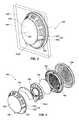
- FIG. 3is an exploded perspective view of the speaker assembly of FIG. 2 ;
- FIG. 4is a side view of the speaker assembly of FIG. 2 ;
- FIG. 5is a rear view of the speaker assembly of FIG. 2 ;
- FIG. 6is a perspective view of a headband of the modular audio system of FIG. 1 ;
- FIG. 7is a front of a wiring assembly of the modular audio system of FIG. 1 ;
- FIG. 8is a front view of another wiring assembly for use with the modular audio system of FIG. 1 ;
- FIGS. 9 through 13are views of modular audio systems including user-wearable accessories comprising mesh liners for receiving speaker assemblies;
- FIGS. 14 through 17are views of modular audio systems including docks for receiving speaker assemblies.
- Disclosed embodimentsrelate generally to speaker assemblies that are attachable to headbands to form headphones, disposable in user-wearable accessories, and connectable to docks. More specifically, disclosed are speaker assemblies and modular audio systems that enable users to use a single set of speaker assemblies with a variety of accessories in a variety of different ways and environments.
- media playermeans and includes any device or system capable of producing an audio signal and connectable to a speaker to convert the audio signal to audible sound.
- media playersinclude portable digital music players, portable CD players, portable cassette players, mobile phones, smartphones, personal digital assistants (PDAs), ebook readers, portable gaming systems, portable DVD players, laptop computers, tablet computers, desktop computers, stereo systems, etc.
- audio jackmeans and includes any connector through which an audio signal (e.g., an analog audio signal) is transmittable and which is used to structurally and electrically connect components of an audio system to one another.
- audio jacksmay be male or female (e.g., plugs or sockets) and may include tip, ring, sleeve (TRS) connectors; tip, sleeve (TS) connectors; tip, ring, ring, sleeve (TRRS) connectors; stereo plugs; mini-jacks; mini-stereo connectors; headphone jacks; and Bantam plugs.
- the modular audio system 100includes a headphone assembly 102 , a wiring system 104 , and a media player 106 .
- the headphone assembly 102is connected to the wiring system 104 such that audio signals carried by the wiring system 104 are transmitted to the headphone assembly 102 .
- the wiring system 104is connected to the media player 106 such that audio signals produced by the media player 106 are transmitted through the wiring system 104 .
- an audio signal from the media player 106may be transmitted through the wiring system 104 to the headphone assembly 102 where it is converted to audible sound.
- the headphone assembly 102may comprise two speaker assemblies 108 and a headband 110 .
- the headband 110may be configured to rest on a user's head and to support the two speaker assemblies 108 when in use.
- the headband 110may also be configured to position the two speaker assemblies 108 attached to the headband 110 proximate (e.g., over) a user's ears such that sound from the speaker assemblies 108 may be more easily heard by the user. Additional detail regarding the headband 110 is provided in connection with FIG. 6 .
- each speaker assembly 108may comprise an audio jack 112 A that may be detachably connected to an audio jack 112 B of the wiring system.
- the audio jack 112 A of each speaker assembly 108may comprise a female tip, ring, sleeve (TRS) connector (e.g., a jack socket) connected to audio jacks 112 B of the wiring system 104 comprising male TRS connectors (e.g., jack plugs).
- TRSsleeve
- the audio jack 112 A of each speaker assembly 108may be integral to the speaker assembly 108 . In other words, there may not be any external wires permanently connected to the speaker assembly 108 connecting the audio jack 112 A to the speaker assembly 108 .
- the speaker assemblies 108may be permanently connected to the wiring system 104 .
- the speaker assemblies 108may be removably attached to the headband 110 .
- the speaker assemblies 108may be detachable from both the wiring system 104 and the headband 110 and connectable to another device or system for use with that other device or system.
- the speaker assemblies 108may be attached to the headband 110 such that manual rotation of the speaker assemblies 108 with respect to the headband 110 detaches the speaker assemblies 108 from the headband 110 .
- the speaker assemblies 108may be quickly and easily removed from such a modular audio system 100 and employed with another modular device or system such that a single set of speaker assemblies 108 are usable with a variety of accessories in a variety of different ways and environments. Additional detail regarding the speaker assemblies 108 is discussed with reference to FIGS. 2 through 5 .
- the wiring system 104may comprise a first wiring assembly 114 and a second wiring assembly 116 .
- the first wiring assembly 114may be detachably connected to the headphone assembly 102
- the second wiring assembly 116may be detachably connected to the media player 106
- the first and second wiring assemblies 114 and 116may be detachably connected to one another to form the wiring system 104 and to connect the headphone assembly 102 to the media player 106
- the wiring system 104may comprise a single, unitary wiring assembly extending from the headphone assembly 102 to the media player 106 or may comprise more than two wiring assemblies interconnected to one another to connect the headphone assembly 102 to the media player 106 . Additional detail regarding the first and second wiring assemblies 114 and 116 is discussed with reference to FIGS. 7 and 8 , respectively.
- the speaker assembly 108comprises an attachment structure 118 configured for attachment to another device or structure (e.g., to a headband 110 (see FIG. 1 )).
- the attachment structure 118may comprise, for example, a frustoconical surface 120 of a housing structure 122 and two or more first attachment features 124 on the frustoconical surface 120 .
- the first attachment features 124may be elongated. For example, the first attachment features 124 may extend across the entire frustoconical surface 120 .
- the first attachment features 124may extend, for example, from a rear plane 126 intersecting the frustoconical surface 120 to a front plane 128 intersecting the frustoconical surface 120 to define the frustoconical shape of the frustoconical surface 120 .
- the first attachment features 124may comprise, for example, slots extending into the frustoconical surface 120 for receiving at least portions of protrusions on another device or structure, as shown in FIG. 2 .
- the first attachment features 124may comprise, for example, protrusions extending from the frustoconical surface 120 for at least partial insertion into slots in another device or structure.
- the first attachment features 124may be generally rectangular in cross-sectional shape, with opposing sidewalls 130 defining the first attachment features 124 being parallel or substantially parallel to one another.
- the opposing sidewalls 130 defining the first attachment features 124may extend in a direction oblique to a central axis 132 of the speaker assembly 108 .
- the first attachment features 124may slant upwardly (when the speaker assembly 108 is oriented with the audio jack 112 A facing downwardly) such that the opposing sidewalls 130 defining the first attachment features 124 may extend in a direction oblique to the central axis 132 of the speaker assembly 108 .
- the speaker assembly 108may comprise a housing structure 122 .
- the housing structure 122may comprise a rear housing portion configured to receive a speaker 134 at least partially within the housing structure 122 .
- An access port 136may enable an audio jack 112 (e.g., an audio jack 112 B of the first wiring assembly 114 (see FIG. 1 )) to detachably connect to an audio jack 112 A connected to the speaker 134 .
- a layer of acoustic felt 138may be interposed between the housing structure 122 and the speaker 134 .
- the speaker 134may be connected to an audio jack 112 A (e.g., a female TRS connector), which may be accessible through the access port 136 .
- Another layer of acoustic felt 138may be interposed between the speaker 134 and a front housing 140 configured for attachment to the housing structure 122 .
- the front housing 140may include a plurality of openings 142 , which may enable sound from the speaker 134 to more easily exit the speaker assembly 108 and be heard by a user.
- the housing structure 122 and the front housing 140When the housing structure 122 and the front housing 140 are attached to one another, they may cooperatively form a housing in which the speaker 134 and the layers of acoustic felt 138 are enclosed.
- the housing structure 122 and the front housing 140may be attached to one another by, for example, screws, bolts, rivets, an adhesive, a snap fit, an interference fit, or other attachments known in the art.
- the audio jack 112 A and the speaker 134 of the speaker assembly 108may be located within the housing (i.e., within the housing structure 122 and the front housing 140 ) and be accessed through the housing.
- the speaker assembly 108may include an optional earpad 144 , which may provide a cushion to increase comfort of a user when the speaker assembly 108 contacts or is pressed against an ear of a user.
- the optional earpad 144may be removably attached to the front housing 140 , for example, by slipping the earpad 144 over and around the front housing 140 .
- the optional earpad 144may also extend around at least a portion of the housing structure 122 in some embodiments.
- the housing structure 122 and the front housing 140may be formed from materials known in the art for use in headphone assemblies 102 (see FIG. 1 ).
- the housing structure 122 and the front housing 140may comprise thermoplastics.
- the speaker 134may be any speaker known in the art for use in headphone assemblies 102 (see FIG. 1 ).
- the first attachment feature 124may slant upwardly (when the speaker assembly 108 is oriented with the audio jack 112 A facing downwardly). More specifically, the first attachment feature 124 may extend at a first angle of inclination 0 1 defined by an included angle between the central axis 132 of the speaker assembly 108 and a central axis 133 of the first attachment feature 124 .
- the central axis 133 of the first attachment feature 124may be located between the sidewalls 130 (e.g., equidistant from each sidewall 130 ) and extend in a direction parallel to the sidewalls 130 .
- the first angle of inclination ⁇ 1 of the first attachment feature 124may be between about 15° and about 75°. More specifically, the first angle of inclination ⁇ 1 of the first attachment feature 124 may be between about 20° and about 60°.
- the first attachment feature 124may extend at a second angle of inclination 0 2 defined by an included angle between a rear axis 135 of the attachment structure 118 and a central axis 133 of the first attachment feature 124 .
- the rear axis 135 of the attachment structure 118may be defined by a line perpendicularly intersecting the central axis 132 (see FIG. 4 ) of the speaker assembly 108 and extending in a vertical direction when the speaker assembly 108 is oriented with the audio jack 112 A facing downwardly.
- the second angle of inclination ⁇ 2 of the first attachment feature 124may be between about 15° and about 75°. More specifically, the second angle of inclination ⁇ 2 of the first attachment feature 124 may be between about 35° and about 55°.
- the headband 110comprises a band 146 configured for placement over a head of a user.
- the band 146may support the speaker assemblies 108 (see FIG. 1 ) by resting on the head of the user.
- the band 146may be collapsible for storage or ease in transport.
- the band 146may include at least one hinge 148 .
- the band 146may include a hinge 148 at an apex of the band 146 , a hinge 148 in a right arm 150 of the band 146 , and a hinge in a left arm 152 of the band 146 .
- the right and left arms 150 and 152 of the band 146may swivel upwardly and the apex of the band 146 may be folded in half to place the headband 110 (and the headphone assembly 102 (see FIG. 1 )) in a compact state for storage or transport.
- the headband 110includes two attachment portions 154 at opposing ends of the band 146 configured for attachment to the attachment structures 118 of speaker assemblies 108 (see FIG. 2 ).
- the attachment portions 154may extend from the respective ends of the right and left arms 150 and 152 of the band 146 .
- the attachment portions 154may be located to position speaker assemblies 108 (see FIG. 1 ) attached to the attachment portions 154 over the ears of a user.
- the right and left arms 150 and 152may be extensible, enabling a user to adjust the positioning of the attachment portions 154 , and the speaker assemblies 108 (see FIG. 1 ) removably attached to the attachment portions 154 , to accommodate different head sizes and ear positions.
- the attachment portions 154may include access indentations 164 configured to accommodate the access ports 136 of the speaker assemblies 108 (see FIG. 3 ).
- Each attachment portion 154may comprise, for example, a mating frustoconical surface 156 configured to abut against and conform to the frustoconical surface 120 of the attachment structure 118 of a speaker assembly 108 ( FIG. 2 ) and two or more second attachment features 158 configured to engage with the first attachment features 124 on the frustoconical surface 120 of the attachment structure 118 of the speaker assembly 108 ( FIG. 2 ).
- the second attachment features 158may be elongated.
- the second attachment features 158may extend across the entire mating frustoconical surface 156 .
- the second attachment features 158may comprise, for example, protrusions extending from the mating frustoconical surface 156 for at least partial insertion into slots of the first attachment features 124 , (see FIG. 2 ), as shown in FIG. 6 .
- the second attachment features 158may comprise, for example, slots extending into the mating frustoconical surface 156 for receiving at least portions of protrusions of the first attachment features 124 .
- the second attachment features 158may be generally rectangular in cross-sectional shape, with opposing sidewalls 160 of the second attachment features 158 being parallel or substantially parallel to one another.
- the opposing sidewalls 160 of the second attachment features 158may extend in a direction oblique to a central axis 162 of the attachment portion 154 .
- the second attachment features 158may slant upwardly (when the access indentations 164 are positioned at a bottom of the headband 110 ) such that the opposing sidewalls 160 of the second attachment features 158 may extend in a direction oblique to a central axis 162 of the attachment portion 154 .
- the headband 110may be formed from materials known in the art for use in headphone assemblies 102 (see FIG. 1 ).
- the headband 110may comprise a thermoplastic.
- the attachment portions 154 of the headband 110 , the attachment structures 118 of the speaker assemblies 108 , or bothmay elastically deform and snap back into shape when the attachment structures 118 of the speaker assemblies 108 are removably attached to the attachment portions 154 .
- the second attachment features 158may snap into the first attachment features 124 and mechanical interference between the second attachment features 158 and the surfaces defining the first attachment features 124 may retain the speaker assemblies 108 attached to the headband 110 .
- the speaker assemblies 108may be removably attached to the headband 110 using a snap fit.
- the speaker assemblies 108may be rotated relative to the headband 110 , which may cause the attachment portions 154 of the headband 110 , the attachment structures 118 of the speaker assemblies 108 , or both to elastically deform and release the speaker assemblies 108 from the headband 110 . More specifically, the speaker assemblies 108 may be rotated about axes transverse to the central axes 132 and 162 of the speaker assemblies 108 and the attachment portion 154 , respectively. Still more specifically, the speaker assemblies 108 may be rotated about axes transverse to the central axes 132 and 162 of the speaker assemblies 108 and the attachment portion 154 , respectively, and passing through the access indentations 164 . Thus, the second attachment features 158 may be extracted from the first attachment features 124 , and the speaker assemblies 108 may be detached from the headband 110 .
- the first wiring assembly 114may comprise two audio jacks 112 B configured to connect to the audio jacks 112 A of the two speaker assemblies 108 and located at the first ends 166 A of two wires 168 A.
- the two audio jacks 112 Bmay comprise male TRS connectors.
- the first wiring assembly 114may further comprise another audio jack 112 C connected to the two wires 168 A at second, opposing ends 170 A of the wires 168 A.
- the other audio jack 112 Cmay comprise a female TRS or tip, ring, ring, sleeve (TRRS) connector.
- TRRSTRS
- the other audio jack 112 Cmay, therefore, be a “Y” juncture connecting the two wires 168 A and splitting an audio signal, for example, into right and left ear portions (e.g., for stereo sound).
- a microphone assembly 172may be connected to one or both of the wires 168 A of the first wiring assembly 114 between the two audio jacks 112 B and the other audio jack 112 B. In other embodiments, such a microphone assembly 172 may not be connected to the wires 168 A of the first wiring assembly 114 , but may be connected to a wire 168 B (see FIG. 8 ) of the second wiring assembly 116 .
- the second wiring assembly 116may comprise a first audio jack 112 D configured to connect to the other audio jack 112 C of the first wiring assembly 114 located at a first end 166 B of a wire 168 B.
- the first audio jack 112 Dmay comprise a male TRS or TRRS connector.
- the first and second wiring assemblies 114 and 116may be permanently connected to one another.
- the first audio jack 112 D of the second wiring assembly 116 and the other audio jack 112 C of the first wiring assembly 114may be omitted, and a permanent “Y” juncture connecting the two wires 168 A of the first wiring assembly 114 and transitioning into the second wiring assembly 116 may be provided.
- the second wiring assembly 116may further comprise a second audio jack 112 D configured to connect to a media player 106 (see FIG. 1 ) and located at a second, opposing end 170 B of the wire 168 B.
- the second audio jack 112 Dmay comprise a male TRRS connector.
- the second wiring assembly 116may further comprise a microphone assembly 172 in some embodiments.
- the microphone assembly 172may include a microphone configured to produce audio signals in response to sounds and to transmit those audio signals to the second audio jack 112 D at the second, opposing end 170 B of the wire 168 B.
- the microphone assembly 172may be connected to the wire 168 B in between the first and second audio jacks 112 D at the first and second, opposing ends 166 B and 170 B of the wire 168 B, respectively.
- the microphone assembly 172may further include additional controls, for example, to increase and decrease volume, start and stop media play, activate voice control. Examples of methods and apparatuses for such a microphone assembly 172 are disclosed at least in U.S. Pat. No. 7,869,608, issued Jan.
- the microphone assembly 172may be located along the length of the wire 168 B at a position proximate to a user's mouth or vocal chords when the modular audio system 100 (see FIG. 1 ) is in use. In some embodiments, a modular audio system 100 (see FIG.
- second wiring assemblies 116may include multiple second wiring assemblies 116 with the microphone assembly 172 located at different positions along the length of the wire 168 B and optionally including different lengths of wire 168 B such that a particular second wiring assembly 116 may be selected to place the microphone assembly 172 proximate the mouth or vocal chords of a user for a chosen activity or configuration of the modular audio system 100 .
- second wiring assemblies 116may not include such microphone assemblies 172 (see FIG. 1 ), and such microphone assemblies 172 may be included in first wiring assemblies 114 (see FIGS. 1 and 7 ).
- the second wiring assembly 116may include an amplifier 173 configured to increase the power of an audio signal transmitted through the second wiring assembly 116 .
- the amplifier 173may comprise a powered, in-line amplifier 173 and may be selectively activated and deactivated by a user to increase or not increase the power of an audio signal transmitted through the second wiring assembly 116 .
- an amplifier 173may be separately included and attachable to one or both of the first and second wiring assemblies 114 and 116 , may be included in-line in the first wiring assembly 114 , or may be disposed in one or both of the speaker assemblies 108 .
- FIGS. 9 through 13are views of modular audio systems 100 (see FIG. 1 ) including user-wearable accessories 174 configured for receiving speaker assemblies 108 .
- a front view of another embodiment of a modular audio system 200is shown.
- Such a modular audio system 200may include a user-wearable accessory 174 A, at least one speaker assembly 108 (e.g., a pair of speaker assemblies 108 ), a wiring system 104 , and a media player 106 .
- the user-wearable accessory 174 Amay comprise, for example, a hood 178 , which may be a portion of a jacket, a coat, a sweater, or a sweatshirt (sometimes referred to in the art as a “hoodie”).
- the speaker assemblies 108may be configured for placement in the hood 178 .
- a mesh liner 176 Aconfigured to receive speaker assemblies 108 may be attached to an inner portion of the hood 178 . Sound from the speaker assemblies 108 may pass through such a mesh liner 176 A in an unmuffled or substantially unmuffled state as compared to sounds passing through other materials that may be used to form liners in hoods 178 .
- the mesh liner 176 Amay be sewn, adhered, attached with hook and loop fasteners (e.g., VELCRO®), or attached with a zipper or zippers to the inner portion of the hood 178 .
- the mesh liner 176 Amay extend from a first side of the hood 178 , around a back of the hood 178 , to a second, opposing side of the hood 178 in some embodiments. In other embodiments, the mesh liner 176 A may only be disposed on the first and second, opposing sides of the hood 178 . The first and second, opposing sides of the hood 178 lined by the mesh liner 176 A may be located proximate a user's ears when the user is wearing the user-wearable accessory 174 A, and particularly when the user dons the hood 178 . In alternative embodiments, the speaker assemblies 108 may be placed in an inner portion of a collar, as disclosed in U.S. Pat. No.
- a mesh liner 176 Amay be attached to the inner portion of such a collar and configured to receive the speaker assemblies 108 .
- the speaker assemblies 108may be placed in the hood 178 on the first and second, opposing sides of the hood 178 .
- openings 180may be formed in the mesh liner 176 A and the speaker assemblies 108 may be slipped through the openings 180 into the mesh liner 176 A.
- the speaker assemblies 108may optionally be secured within the mesh liner 176 A by closing the openings 180 , for example, using zippers, buttons, snaps, or hook and loop fasteners.
- the mesh liner 176 Amay include discrete compartments 182 for containing the speaker assemblies 108 .
- the speaker assemblies 108may be movable within the discrete compartments 182 , and specific motions may enable a user to control the media player 106 , as disclosed in U.S. Provisional Patent Application No. 61/502,240, filed Jun. 28, 2011, to Kelly et al., the disclosure of which is incorporated herein in its entirety by this reference.
- the mesh liner 176 Amay include at least one aperture through which the wiring system 104 , or at least portions thereof, may pass.
- the first wiring assembly 114may extend from the speaker assemblies 108 within the mesh liner 176 A to a rear of the hood 178 and pass through an aperture in the mesh liner 176 A at the rear of the hood 178 .
- the wiring system 104may extend from the speaker assemblies 108 , through the openings 180 through which the speaker assemblies 108 were inserted, and out of the hood 178 .
- the second wiring assembly 116may connect to the first wiring assembly 114 and extend out of the hood 178 to a media player 106 (e.g., in a pocket of the user-wearable accessory 174 A).
- the microphone assembly 172may be located outside the hood 178 because the microphone assembly 172 is connected to the wire 168 B of the second wiring assembly 116 , and not to the wires 168 A of the first wiring assembly 114 .
- the microphone assembly 172may be distanced from the speaker assemblies 108 to position the microphone assembly 172 near the mouth or vocal cords of a user.
- a length L of the wiring system 104including audio jacks 112 (e.g., audio jacks 112 B, 112 C, and 112 D) and wire 168 A and 168 B, between the audio jack 112 A of the speaker assembly 108 and the microphone assembly 172 may be between about 35 cm and about 65 cm. More specifically, the length L of the wiring system 104 between the audio jack 112 A of the speaker assembly 108 and the microphone assembly 172 may be between about 45 cm and about 55 cm.
- the speaker assemblies 108may be secured within the mesh liner 176 A in some embodiments.
- the openings 180 of the discrete compartments 182 formed in the mesh liner 176 Amay be secured shut by buttoning, snapping, zipping, or securing using hook and loop fasteners the mesh liner 176 A to itself or to the hood 178 to close the openings 180 .
- the openings 180may remain open, and gravity and friction may keep the speaker assemblies 108 in the mesh liner 176 A.
- a cross-sectional view of another embodiment of a modular audio system 300may include a user-wearable accessory 174 B, at least one speaker assembly 108 (e.g., a pair of speaker assemblies 108 ), a wiring system 104 , and a media player 106 .
- the user-wearable accessory 174 Bmay comprise, for example, a skull cap (sometimes referred to in the art as a tuque or a “beanie”), which may comprise a knit or a woven fabric.
- a skull capsometimes referred to in the art as a tuque or a “beanie”
- the speaker assemblies 108may be configured for placement in the skull cap.
- a mesh liner 176 Bconfigured to receive speaker assemblies 108 may be attached to an inner portion of the skull cap.
- the mesh liner 176 Bmay be sewn, adhered, attached with hook and loop fasteners (e.g., VELCRO®), or attached with a zipper or zippers to the inner portion of the skull cap.
- the mesh liner 176 Bmay extend entirely around the skull cap in some embodiments. In other embodiments, the mesh liner 176 B may extend from a first side of the skull cap, around a back of the skull cap, to a second, opposing side of the skull cap, or may only be disposed on the first and second, opposing sides of the skull cap.
- the first and second, opposing sides of the skull cap lined by the mesh liner 176 Bmay be located proximate a user's ears when the user is wearing the skull cap.
- the speaker assemblies 108may be disposed in the mesh liner 176 B on the first and second, opposing sides of the skull cap.
- openings 180may be formed in the mesh liner 176 B and the speaker assemblies 108 may be slipped through the openings 180 into the mesh liner 176 B.
- the speaker assemblies 108may optionally be secured within the mesh liner 176 B by closing the openings 180 .
- the mesh liner 176 Bmay include discrete compartments 182 for containing the speaker assemblies 108 .
- the speaker assemblies 108may be movable within the discrete compartments 182 , and specific motions may enable a user to control the media player 106 , as discussed previously with reference to FIG. 9 .
- the speaker assemblies 108may be secured within the mesh liner 176 B in some embodiments. In alternative embodiments, the openings 180 may remain open, and gravity and friction may keep the speaker assemblies 108 in the mesh liner 176 B.
- the mesh liner 176 Bmay include at least one aperture through which the wiring system 104 , or at least portions thereof, may pass.
- the first wiring assembly 114may extend from the speaker assemblies 108 within the mesh liner 176 B to a rear of the skull cap and connect to the second wiring assembly 116 within the mesh liner 176 B at the rear of the skull cap.
- the second wiring assembly 116may extend through an aperture at the rear of the skull cap out of the mesh liner 176 B and the skull cap to a media player 106 .
- the microphone assembly 172FIG.
- the wiring system 104may extend from the speaker assemblies 108 , through the openings 180 through which the speaker assemblies 108 were inserted, and out of the skull cap.
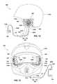
- a side cross-sectional view of another embodiment of a modular audio system 400is shown.
- a modular audio system 400may include a user-wearable accessory 174 C, at least one speaker assembly 108 (e.g., a pair of speaker assemblies 108 ), a wiring system 104 , and a media player 106 .
- the user-wearable accessory 174 Cmay comprise, for example, a helmet. In this view, an interior side of the helmet is shown.
- the speaker assemblies 108may be configured for placement in the helmet.
- a mesh liner 176 Cconfigured to receive speaker assemblies 108 may be attached to an inner portion of the helmet.
- the mesh liner 176 Cmay be sewn, adhered, attached with hook and loop fasteners (e.g., VELCRO®), or attached with a zipper or zippers to the inner portion of the helmet.
- the mesh liner 176 Cmay only be disposed on a first side and a second, opposing side of the helmet in some embodiments. In other embodiments, the mesh liner 176 C may extend from a first side of the helmet, around a back of the helmet, to a second, opposing side of the helmet, or may extend entirely around the helmet.
- the first and second, opposing sides of the helmet lined by the mesh liner 176 Cmay be located proximate a user's ears when the user is wearing the helmet.
- the speaker assemblies 108may be disposed in the mesh liner 176 C on the first and second, opposing sides of the helmet (only one speaker assembly 108 on one side is shown in FIG. 12 ).
- openings 180may be formed in the mesh liner 176 C and the speaker assemblies 108 may be slipped through the openings 180 into the mesh liner 176 C.
- the speaker assemblies 108may optionally be secured within the mesh liner 176 C by closing the openings 180 .
- the mesh liner 176 Cmay form discrete compartments 182 for containing the speaker assemblies 108 .
- the speaker assemblies 108may be movable within the discrete compartments 182 , and specific motions may enable a user to control the media player 106 , as discussed previously with reference to FIG. 9 .
- the speaker assemblies 108may be secured within the mesh liner 176 C in some embodiments. In alternative embodiments, the openings 180 may remain open, and gravity and friction may keep the speaker assemblies 108 in the mesh liner 176 C.
- the mesh liner 176 Cmay include at least one aperture through which the wiring system 104 , or at least portions thereof, may pass.
- the first wiring assembly 114may extend from the speaker assemblies 108 , through the openings 180 through which the speaker assemblies 108 were inserted, and out of the helmet at the first and second, opposing sides of the helmet.
- the wiring system 104may extend from the speaker assemblies 108 , through apertures in the mesh liner 176 C, to a rear of the helmet where the wiring system 104 may exit the helmet.
- the first wiring assembly 114may connect to the second wiring assembly 116 outside of the mesh liner 176 C and outside of the helmet, and the second wiring assembly 116 may extend to a media player 106 .
- the microphone assembly 172may be located outside the mesh liner 176 C and outside the user-wearable accessory 174 C (i.e., outside the helmet).
- a front view of another embodiment of a modular audio system 500may include a user-wearable accessory 174 D, at least one speaker assembly 108 (e.g., a pair of speaker assemblies 108 ), a wiring system 104 , and a media player 106 .
- the user-wearable accessory 174 Dmay comprise, for example, a full-face helmet.
- the speaker assemblies 108may be configured for placement in the full-face helmet.
- a mesh liner 176 Dconfigured to receive speaker assemblies 108 may be attached to an inner portion of the full-face helmet.
- the mesh liner 176 Dmay be sewn, adhered, attached with hook and loop fasteners (e.g., VELCRO®), or attached with a zipper or zippers to the inner portion of the full-face helmet.
- the mesh liner 176 Dmay extend from a first side of the full-face helmet, around a back of the full-face helmet, to a second, opposing side of the full-face helmet in some embodiments. In other embodiments, the mesh liner 176 D may extend entirely around the interior of the full-face helmet, or may only be disposed on the first and second, opposing sides of the full-face helmet.
- the first and second, opposing sides of the full-face helmet lined by the mesh liner 176 Dmay be located proximate a user's ears when the user is wearing the full-face helmet.
- the speaker assemblies 108may be disposed in the mesh liner 176 D on the first and second, opposing sides of the full-face helmet.
- openings 180may be formed in the mesh liner 176 D and the speaker assemblies 108 may be slipped through the openings 180 into the mesh liner 176 D.
- the speaker assemblies 108may optionally be secured within the mesh liner 176 D by closing the openings 180 .
- the mesh liner 176 Dmay form discrete compartments 182 for containing the speaker assemblies 108 .
- the discrete compartments 182may have a greater depth D 1 than a depth D 2 of a remainder of the mesh liner 176 D extending around the rear of the full-face helmet in which at least a portion of the first wiring assembly 114 may extend in some embodiments.
- the mesh liner 176 Dmay have a uniform depth.
- the speaker assemblies 108may be movable within the discrete compartments 182 , and specific motions may enable a user to control the media player 106 , as discussed previously with reference to FIG. 9 .
- the speaker assemblies 108may be secured within the mesh liner 176 D in some embodiments.
- the openings 180may remain open, and gravity and friction may keep the speaker assemblies 108 in the mesh liner 176 D.
- the mesh liner 176 Dmay include at least one aperture through which the wiring system 104 , or at least portions thereof, may pass.
- the first wiring assembly 114may extend from the speaker assemblies 108 within the mesh liner 176 D to the rear of the full-face helmet, through an aperture in the mesh liner 176 D, and out of the full-face helmet at the rear of the helmet.
- the wiring system 104may extend from the speaker assemblies 108 , through the openings 180 through which the speaker assemblies 108 were inserted, and out of the full-face helmet.
- the first wiring assembly 114may connect to the second wiring assembly 116 outside of the mesh liner 176 D and outside of the full-face helmet, and the second wiring assembly 116 may extend to a media player 106 .
- the microphone assembly 172may be located outside the mesh liner 176 D and outside the user-wearable accessory 174 D (i.e., outside the full-face helmet) because the microphone assembly 172 is connected to the wire 168 B of the second wiring assembly 116 , and not to the wires 168 A of the first wiring assembly 114 .
- FIGS. 14 through 17are views of modular audio systems 100 including docks 184 for receiving speaker assemblies 108 .
- a perspective view of a modular audio system 600is shown.
- Such a modular audio system 600includes a dock 184 A and at least one speaker assembly 108 (e.g., a pair of speaker assemblies 108 ) connected to and supported by the dock 184 A.
- the dock 184 Amay comprise, for example, a goggle case for holding ski, snowboard, motorcycle, or other types of outdoor goggles.
- the goggle casemay include a first compartment 186 in which goggles may be disposed, and a second compartment 188 in which the speaker assemblies 108 may be disposed.
- Audio jacks 112 Bmay be exposed within the second compartment 188 , and the audio jacks 112 B may be connected to the audio jacks 112 A of the speaker assemblies 108 .
- the audio jacks 112 Bmay be structurally attached to the goggle case.
- the audio jacks 112 A of the speaker assemblies 108may be connected to the audio jacks 112 B of the dock 184 A simply by lowering the speaker assemblies 108 into place in the second compartment 188 .
- the speaker assemblies 108may be at least partially structurally supported by the audio jacks 112 B.
- Wires 168 A or other electrical connectionsmay electrically connect the audio jacks 112 B to a media player 106 (see FIG.
- the speaker assemblies 108may optionally be at least partially supported by a portion of the goggle case defining the second compartment 188 .
- the goggle casemay include attachment portions 154 similar to those described previously in connection with FIG. 6 to which the speaker assemblies 108 may be removably attached.
- the dock 184 Amay optionally include an electrical power source and an amplifier (not shown) to increase volume output of the speaker assemblies 108 .
- FIG. 15a perspective view of another embodiment of a modular audio system 700 is shown.
- a modular audio system 700includes a dock 184 B and at least one speaker assembly 108 (e.g., a pair of speaker assemblies 108 ) connected to and supported by the dock 184 B.
- the dock 184 Bmay comprise, for example, a pair of sandals.
- the sandalsmay each include recesses 190 in which the speaker assemblies 108 may be disposed.
- the sandalsmay include removable inserts 192 in the shape of speaker assemblies 108 to occupy the recesses 190 when a user wears the sandals.
- the recesses 190may be configured in a manner similar to the attachment portions 154 described previously in connection with FIG.
- the speaker assemblies 108may be removably attached to the sandals within the recesses 190 .
- the speaker assemblies 108may be connected to audio jacks and wiring (not shown) embedded within the sandals.
- a wire 168 B having audio jacks 112 D on the ends of the wire 168 Bmay connect the sandals to one another.
- a second wiring assembly 116may connect one of the sandals to a media player 106 .
- the dock 184 Bmay optionally include an electrical power source and an amplifier (not shown), such as, for example, embedded within the sandals, to increase volume output of the speaker assemblies 108 .
- FIG. 16a perspective view of another embodiment of a modular audio system 800 is shown.
- a modular audio system 800includes a dock 184 C and at least one speaker assembly 108 (e.g., a single speaker assembly 108 ) connected to and supported by the dock 184 C.
- the dock 184 Cmay comprise, for example, a media player case (e.g., a phone case).
- the media player casemay include a recess 190 in which the speaker assembly 108 may be disposed.
- the media player casemay include a removable insert 192 (see FIG. 15 ) in the shape of a speaker assembly 108 to occupy the recess 190 when the speaker assembly 108 is not connected to the dock 184 C.
- the recesses 190may be configured in a manner similar to the attachment portions 154 described previously in connection with FIG. 6 , and thus the speaker assemblies 108 may be removably attached to the media player case within the recess 190 .
- the recesses 190may be configured such that the speaker assembly 108 may simply be lowered into the recesses 190 to both structurally and electrically connect the speaker assembly 108 to the dock 184 C.
- the speaker assembly 108may be structurally and electrically connected to an audio jack (not shown) secured to the media player case, which may connect the speaker assembly 108 to the media player 106 contained within the media player case.
- the dock 184 Cmay optionally include an electrical power source and an amplifier (not shown), such as, for example, embedded within the media player case, to increase volume output of the speaker assembly 108 .
- FIG. 17a perspective view of another embodiment of a modular audio system 900 is shown.
- a modular audio system 900includes a dock 184 D and at least one speaker assembly 108 (e.g., a pair of speaker assemblies 108 ) connected to and supported by the dock 184 D.
- the dock 184 Dmay comprise, for example, a distinct stand.
- the distinct standmay include a recess 190 ′ in which the speaker assemblies 108 may be disposed.
- the recess 190 ′may be configured such that the speaker assemblies 108 may simply be lowered into the recess 190 ′ to both structurally and electrically connect the speaker assemblies 108 to the dock 184 D.
- the speaker assemblies 108may be quickly and easily swapped between accessories, such as, for example, docks 184 , user-wearable accessories 174 , and headbands 110 to adapt the speaker assemblies 108 for use in a variety of different environments.
- Each speaker assembly 108may be electrically and structurally connected to an audio jack (not shown) secured to the dock 184 D and exposed within the recess 190 ′, which may connect each speaker assembly 108 to a media player 106 (see FIG. 1 ) attached to the distinct stand (e.g., using a wired connection) or wirelessly connected to the distinct stand.
- the audio jacksmay be physically integral to the dock 184 D and may structurally support the speaker assemblies 108 in addition to providing direct electrical connection between the dock 184 D and the speaker assemblies 108 .
- a connection between the speaker assemblies 108 and the dock 184 Dmay not be a wired connection, but a direct structural and electrical connection between the speaker assemblies 108 and the dock 184 D.
- the dock 184 Dmay optionally include an electrical power source and an amplifier (not shown), such as, for example, located within the distinct stand, to increase volume output of the speaker assembly 108 .
Landscapes
- Physics & Mathematics (AREA)
- Engineering & Computer Science (AREA)
- Acoustics & Sound (AREA)
- Signal Processing (AREA)
- Helmets And Other Head Coverings (AREA)
- Health & Medical Sciences (AREA)
- Otolaryngology (AREA)
Abstract
Description
Claims (10)
Priority Applications (3)
| Application Number | Priority Date | Filing Date | Title |
|---|---|---|---|
| US13/451,299US9237395B2 (en) | 2009-11-25 | 2012-04-19 | Modular audio systems and related assemblies and methods |
| US13/732,193US9100745B2 (en) | 2012-01-09 | 2012-12-31 | Modular audio devices configured to emit differing sound profiles and related methods |
| US14/741,043US9319770B2 (en) | 2012-01-09 | 2015-06-16 | Audio devices configured to emit differing sound profiles and related methods |
Applications Claiming Priority (3)
| Application Number | Priority Date | Filing Date | Title |
|---|---|---|---|
| US12/664,189US8542859B2 (en) | 2008-11-25 | 2009-11-25 | Interchangeable headphone audio system |
| US201261584660P | 2012-01-09 | 2012-01-09 | |
| US13/451,299US9237395B2 (en) | 2009-11-25 | 2012-04-19 | Modular audio systems and related assemblies and methods |
Publications (2)
| Publication Number | Publication Date |
|---|---|
| US20130177195A1 US20130177195A1 (en) | 2013-07-11 |
| US9237395B2true US9237395B2 (en) | 2016-01-12 |
Family
ID=55068703
Family Applications (1)
| Application Number | Title | Priority Date | Filing Date |
|---|---|---|---|
| US13/451,299Active2033-09-18US9237395B2 (en) | 2009-11-25 | 2012-04-19 | Modular audio systems and related assemblies and methods |
Country Status (1)
| Country | Link |
|---|---|
| US (1) | US9237395B2 (en) |
Cited By (2)
| Publication number | Priority date | Publication date | Assignee | Title |
|---|---|---|---|---|
| US20150139464A1 (en)* | 2013-04-01 | 2015-05-21 | Puma SE | Speaker system |
| US20170042270A1 (en)* | 2015-08-14 | 2017-02-16 | Sound Team Enterprise Co., Ltd. | Combination knitted hat and earphone assembly |
Families Citing this family (49)
| Publication number | Priority date | Publication date | Assignee | Title |
|---|---|---|---|---|
| US9237395B2 (en) | 2009-11-25 | 2016-01-12 | Skullcandy, Inc. | Modular audio systems and related assemblies and methods |
| US9467780B2 (en) | 2010-01-06 | 2016-10-11 | Skullcandy, Inc. | DJ mixing headphones |
| US9532126B1 (en) | 2010-01-06 | 2016-12-27 | Skullcandy, Inc. | Audio earbud headphone for improved in-ear retention |
| US8515115B2 (en) | 2010-01-06 | 2013-08-20 | Skullcandy, Inc. | Audio earbud headphone with extended curvature |
| US9422094B2 (en) | 2011-11-15 | 2016-08-23 | Skullcandy, Inc. | Packaging for headphones, packaged headphones, and related methods |
| US8942403B2 (en) | 2011-11-18 | 2015-01-27 | Skullcandy, Inc. | Wiring harness for clothing, electronic devices including such a wiring harness, and garments incorporating such a wiring harness and electronic device |
| US9100745B2 (en) | 2012-01-09 | 2015-08-04 | Skullcandy, Inc. | Modular audio devices configured to emit differing sound profiles and related methods |
| US9439467B2 (en) | 2012-01-24 | 2016-09-13 | Skullcandy, Inc. | Accessory structures for connection between straps and related methods |
| US8965028B2 (en) | 2012-08-23 | 2015-02-24 | Skullcandy, Inc. | Speakers, headphones, and kits related to vibrations in an audio system, and methods for forming same |
| US9414145B2 (en) | 2013-03-15 | 2016-08-09 | Skullcandy, Inc. | Customizable headphone audio driver assembly, headphone including such an audio driver assembly, and related methods |
| US20150220164A1 (en)* | 2013-06-27 | 2015-08-06 | Intel Corporation | Techniques for using a cable as an input device |
| USD733682S1 (en) | 2013-09-25 | 2015-07-07 | Skullcandy, Inc. | Portable speaker |
| TWM489441U (en)* | 2014-01-29 | 2014-11-01 | jun-xuan Lin | Earphone with adjustable line length |
| USD728533S1 (en) | 2014-03-31 | 2015-05-05 | Skullcandy, Inc. | Headphone |
| USD731457S1 (en) | 2014-04-25 | 2015-06-09 | Apple Inc. | Audio listening system |
| USD750042S1 (en) | 2014-07-14 | 2016-02-23 | Skullcandy, Inc. | Headphone microphone |
| USD758336S1 (en) | 2014-07-25 | 2016-06-07 | Skullcandy, Inc. | Portable speaker |
| USD758989S1 (en) | 2014-07-25 | 2016-06-14 | Skullcandy, Inc. | Portable speaker |
| USD757678S1 (en) | 2014-07-25 | 2016-05-31 | Skullcandy, Inc. | Portable speaker |
| CN105578330A (en)* | 2014-10-15 | 2016-05-11 | 深圳富泰宏精密工业有限公司 | Earphone clamping device and earphone assembly using the same |
| EP3041261B1 (en) | 2014-12-31 | 2020-05-06 | Skullcandy, Inc. | Speaker assemblies for passive generation of vibrations and related headphone devices and methods |
| EP3041258B1 (en) | 2014-12-31 | 2018-02-28 | Skullcandy, Inc. | Methods of generating tactile user feedback utilizing headphone devices and related systems |
| USD757680S1 (en) | 2015-01-05 | 2016-05-31 | Skullcandy, Inc. | Headphone |
| US20160206032A1 (en)* | 2015-01-19 | 2016-07-21 | Anthony Stewart | Clothing Article With Integrated Electronics Holder |
| US9648412B2 (en) | 2015-02-06 | 2017-05-09 | Skullcandy, Inc. | Speakers and headphones related to vibrations in an audio system, and methods for operating same |
| US20160374421A1 (en)* | 2015-02-18 | 2016-12-29 | James Washington | Hooded Sweatshirt with Integral Speakers |
| CN106210946A (en)* | 2015-05-05 | 2016-12-07 | 酷码科技股份有限公司 | Customized earphone structure and detachable sound playing module thereof |
| USD782995S1 (en)* | 2015-06-25 | 2017-04-04 | Focal Jmlab | Headphone |
| USD783572S1 (en)* | 2015-06-25 | 2017-04-11 | Focal Jmlab | Headphone |
| US9918154B2 (en) | 2015-07-30 | 2018-03-13 | Skullcandy, Inc. | Tactile vibration drivers for use in audio systems, and methods for operating same |
| US9584901B1 (en) | 2015-09-07 | 2017-02-28 | Bose Corporation | Convertible headphone system |
| USD824365S1 (en) | 2015-11-18 | 2018-07-31 | Skullcandy, Inc. | Portable speaker |
| USD824879S1 (en) | 2015-11-18 | 2018-08-07 | Skullcandy, Inc. | Portable speaker |
| WO2017120380A1 (en)* | 2016-01-06 | 2017-07-13 | New Era Cap Co., Inc. | Knit hat having integrated sweatband |
| RU2713042C1 (en)* | 2016-06-29 | 2020-02-03 | 3М Инновейтив Пропертиз Компани | Method of modification of device for protection of hearing organs and device for protection of hearing organs |
| US10154335B1 (en)* | 2016-09-06 | 2018-12-11 | Minh Dung Hoang | Interchangeable speaker assembly and method of use |
| US10448520B2 (en) | 2016-10-03 | 2019-10-15 | Google Llc | Voice-activated electronic device assembly with separable base |
| US10535966B2 (en) | 2016-10-03 | 2020-01-14 | Google Llc | Planar electrical connector for an electronic device |
| GB2554815B (en) | 2016-10-03 | 2021-03-31 | Google Llc | Voice-activated electronic device assembly with separable base |
| USD847778S1 (en)* | 2017-03-17 | 2019-05-07 | Muzik Inc. | Video/audio enabled removable insert for a headphone |
| US20190343686A1 (en)* | 2017-10-18 | 2019-11-14 | Restorear, LLC | Devices for Application of Localized Hypothermic Therapy to the Human Ear |
| JP1617794S (en)* | 2018-01-22 | 2018-11-12 | ||
| USD891396S1 (en)* | 2018-06-28 | 2020-07-28 | Focal Jmlab | Stellia audio headset |
| JP1675804S (en)* | 2020-07-17 | 2021-01-04 | ||
| JP7643040B2 (en)* | 2020-12-28 | 2025-03-11 | カシオ計算機株式会社 | Speaker device and hood-type speaker device |
| USD975052S1 (en)* | 2021-04-01 | 2023-01-10 | Yueping Zeng | Headset |
| USD981363S1 (en)* | 2021-04-13 | 2023-03-21 | Microsoft Corporation | Headset |
| USD991907S1 (en)* | 2022-05-18 | 2023-07-11 | Focal Jmlab | Headset |
| USD1071894S1 (en)* | 2023-08-28 | 2025-04-22 | Dell Products L.P. | Headset |
Citations (61)
| Publication number | Priority date | Publication date | Assignee | Title |
|---|---|---|---|---|
| US1329029A (en) | 1918-04-13 | 1920-01-27 | John S Timmons | Telephone apparatus |
| US1418388A (en) | 1918-05-08 | 1922-06-06 | Benjamin F Miessner | Speaking-tube apparatus for aircraft |
| FR2249510A1 (en) | 1973-10-24 | 1975-05-23 | Palmaer Tore | Combined earphone and microphone support - is pivotally connected to strap around the head or spectacles |
| US3938614A (en) | 1972-06-20 | 1976-02-17 | Aktiebolaget Lennartsfors Mekaniska Verkstad | Cushion member for sound-proof sealing |
| US5551089A (en) | 1995-01-10 | 1996-09-03 | Whidden; Jenna | Designer earmuff having interchangeable ear muff pieces |
| US5625171A (en) | 1995-05-09 | 1997-04-29 | Marshall; Christina M. | Interchangeable earpiece for stereo listening |
| US5625903A (en) | 1996-02-26 | 1997-05-06 | Schultz; Michael A. | Headband with adjustable speaker supporting means |
| KR200220309Y1 (en) | 2000-11-27 | 2001-04-16 | 김용국 | head set |
| KR20020052658A (en) | 2000-12-26 | 2002-07-04 | 윤종용 | Head Mounted Display |
| US20020094094A1 (en) | 2001-01-17 | 2002-07-18 | Seo Won K-Tec., Inc. | Headset device |
| US20030007660A1 (en) | 2000-01-07 | 2003-01-09 | Naotaka Tsunoda | Headphone device |
| WO2003053096A1 (en) | 2001-12-18 | 2003-06-26 | Sony Corporation | Headset |
| US20040005071A1 (en) | 2002-07-02 | 2004-01-08 | Siskin David R. | Ear warming article including electronic device and easily interchangeable advertising areas |
| US20040157649A1 (en) | 2002-07-26 | 2004-08-12 | James Jannard | Wireless interactive headset |
| US20060013410A1 (en)* | 2004-04-20 | 2006-01-19 | Wurtz Michael J | Mobile-telephone adapters for automatic-noise-reduction headphones |
| KR100631863B1 (en) | 1998-08-13 | 2006-10-04 | 소니 가부시끼 가이샤 | Sound system and headphones |
| US7120268B2 (en)* | 2001-10-31 | 2006-10-10 | Sony Corporation | Headphone |
| CA2515558A1 (en) | 2005-08-10 | 2007-02-10 | Skullcandy, Inc. | Personal portable integrator for music player and mobile phone |
| US7187948B2 (en) | 2002-04-09 | 2007-03-06 | Skullcandy, Inc. | Personal portable integrator for music player and mobile phone |
| EP1760896A1 (en) | 2005-08-29 | 2007-03-07 | Scullcandy Inc. | Product for carrying audio and telephonic communication devices |
| USD549883S1 (en) | 2006-02-16 | 2007-08-28 | Dion Stephane | Motocross helmet |
| CN200980154Y (en) | 2006-07-21 | 2007-11-21 | 林炳宏 | Headphone structure of the eye mask |
| CN101095370A (en) | 2005-01-04 | 2007-12-26 | 摩托罗拉公司 | Audio headphones having wireless transceiver and analog audio input |
| US7388960B2 (en) | 2005-01-19 | 2008-06-17 | Ching-Chang Kuo | Multimedia speaker headphone |
| US20080144872A1 (en)* | 2006-03-09 | 2008-06-19 | Phillips Aaron M | Headgear and integrated music player |
| US7519192B1 (en) | 2005-09-13 | 2009-04-14 | Logan Laycock | Wired clothing and earphones |
| US20090235426A1 (en) | 2008-03-19 | 2009-09-24 | Sean Curtis Johnston | Hooded garment with an integrated tubular collar having a zipper |
| US20100111349A1 (en)* | 2008-10-31 | 2010-05-06 | Ume Voice, Inc. | Modular Input/Output Headset And Method Of Use |
| WO2010068495A2 (en) | 2008-11-25 | 2010-06-17 | Skullcandy, Inc. | Interchangeable headphone audio system |
| USD623627S1 (en) | 2010-01-06 | 2010-09-14 | Skullcandy, Inc. | Optic-shaped headphones |
| USD624057S1 (en) | 2010-01-06 | 2010-09-21 | Skullcandy, Inc. | Audio ear bud headphone with extended curvature |
| WO2010124190A2 (en) | 2009-04-24 | 2010-10-28 | Skullcandy, Inc. | Wireless synchronization mechanism |
| US20100284525A1 (en) | 2009-05-08 | 2010-11-11 | Apple Inc. | Transfer of multiple microphone signals to an audio host device |
| US7869608B2 (en) | 2008-01-14 | 2011-01-11 | Apple Inc. | Electronic device accessory |
| USD641003S1 (en) | 2010-07-22 | 2011-07-05 | Skullcandy, Inc. | Headphone band with angled shape |
| WO2011085096A2 (en) | 2010-01-06 | 2011-07-14 | Skullcandy, Inc. | Dj mixing headphones |
| USD650356S1 (en) | 2010-01-06 | 2011-12-13 | Skullcandy, Inc. | Eyeglass shaped headphones |
| WO2012024656A2 (en) | 2010-08-20 | 2012-02-23 | Skullcandy, Inc. | Audio ear bud headphone with extended curvature |
| US20120148052A1 (en)* | 2010-12-10 | 2012-06-14 | David Adam | System, Method, and Apparatus for Conveying a Signal to One or More Devices |
| US20120275615A1 (en) | 2010-01-06 | 2012-11-01 | Skullcandy, Inc. | Dj mixing headphones |
| USD673140S1 (en) | 2011-12-19 | 2012-12-25 | Skullcandy, Inc. | Headphone |
| USD673136S1 (en) | 2011-11-18 | 2012-12-25 | Skullcandy, Inc. | Headphone |
| USD674376S1 (en) | 2011-10-10 | 2013-01-15 | Skull Candy, Inc. | Headphone |
| USD674372S1 (en) | 2011-10-10 | 2013-01-15 | Skullcandy, Inc. | Headphone |
| USD676023S1 (en) | 2012-01-24 | 2013-02-12 | Skullcandy, Inc. | Wireless communication device |
| USD676024S1 (en) | 2012-01-24 | 2013-02-12 | Skullcandy, Inc. | Wireless communication device |
| USD677241S1 (en) | 2011-12-19 | 2013-03-05 | Skullcandy, Inc. | Headphone |
| US20130118944A1 (en) | 2011-11-15 | 2013-05-16 | Mark T. Niiro | Packaging for headphones, packaged headphones, and related methods |
| US20130130540A1 (en) | 2011-11-18 | 2013-05-23 | Skullcandy, Inc. | Wiring harness for clothing, electronic devices including such a wiring harness, and garments incorporating such a wiring harness and electronic device |
| USD685767S1 (en) | 2011-12-19 | 2013-07-09 | Skullcandy, Inc. | Headphone |
| USD685759S1 (en) | 2011-12-19 | 2013-07-09 | Skullcandy, Inc. | Headphone |
| US20130177195A1 (en) | 2009-11-25 | 2013-07-11 | Skullcandy, Inc. | Modular audio systems and related assemblies and methods |
| US20130177165A1 (en) | 2012-01-09 | 2013-07-11 | Skullcandy, Inc. | Modular audio devices configured to emit differing sound profiles and related methods |
| US20130185905A1 (en) | 2012-01-24 | 2013-07-25 | Skullcandy, Inc. | Accessory structures for connection between straps and related methods |
| US20130208909A1 (en) | 2010-09-14 | 2013-08-15 | Phonak Ag | Dynamic hearing protection method and device |
| US8515115B2 (en) | 2010-01-06 | 2013-08-20 | Skullcandy, Inc. | Audio earbud headphone with extended curvature |
| USD689464S1 (en) | 2012-08-22 | 2013-09-10 | Skullcandy, Inc. | Headset |
| USD691582S1 (en) | 2012-08-22 | 2013-10-15 | Skullcandy, Inc. | Headset |
| US20140056459A1 (en) | 2012-08-23 | 2014-02-27 | Skullcandy, Inc. | Speakers, headphones, and kits related to vibrations in an audio system, and methods for forming same |
| USD701196S1 (en) | 2012-12-26 | 2014-03-18 | Skullcandy, Inc. | Headphone |
| USD701197S1 (en) | 2012-12-26 | 2014-03-18 | Skullcandy, Inc. | Headphone |
- 2012
- 2012-04-19USUS13/451,299patent/US9237395B2/enactiveActive
Patent Citations (82)
| Publication number | Priority date | Publication date | Assignee | Title |
|---|---|---|---|---|
| US1329029A (en) | 1918-04-13 | 1920-01-27 | John S Timmons | Telephone apparatus |
| US1418388A (en) | 1918-05-08 | 1922-06-06 | Benjamin F Miessner | Speaking-tube apparatus for aircraft |
| US3938614A (en) | 1972-06-20 | 1976-02-17 | Aktiebolaget Lennartsfors Mekaniska Verkstad | Cushion member for sound-proof sealing |
| FR2249510A1 (en) | 1973-10-24 | 1975-05-23 | Palmaer Tore | Combined earphone and microphone support - is pivotally connected to strap around the head or spectacles |
| US5551089A (en) | 1995-01-10 | 1996-09-03 | Whidden; Jenna | Designer earmuff having interchangeable ear muff pieces |
| US5625171A (en) | 1995-05-09 | 1997-04-29 | Marshall; Christina M. | Interchangeable earpiece for stereo listening |
| US5625903A (en) | 1996-02-26 | 1997-05-06 | Schultz; Michael A. | Headband with adjustable speaker supporting means |
| KR100631863B1 (en) | 1998-08-13 | 2006-10-04 | 소니 가부시끼 가이샤 | Sound system and headphones |
| US20030007660A1 (en) | 2000-01-07 | 2003-01-09 | Naotaka Tsunoda | Headphone device |
| US7245736B2 (en) | 2000-01-07 | 2007-07-17 | Sony Corporation | Headphone device |
| KR200220309Y1 (en) | 2000-11-27 | 2001-04-16 | 김용국 | head set |
| KR20020052658A (en) | 2000-12-26 | 2002-07-04 | 윤종용 | Head Mounted Display |
| KR100399768B1 (en) | 2000-12-26 | 2003-09-26 | 삼성전자주식회사 | Head Mounted Display |
| US20020094094A1 (en) | 2001-01-17 | 2002-07-18 | Seo Won K-Tec., Inc. | Headset device |
| US7120268B2 (en)* | 2001-10-31 | 2006-10-10 | Sony Corporation | Headphone |
| WO2003053096A1 (en) | 2001-12-18 | 2003-06-26 | Sony Corporation | Headset |
| KR20040065582A (en) | 2001-12-18 | 2004-07-22 | 소니 가부시끼 가이샤 | Headset |
| US20050008184A1 (en) | 2001-12-18 | 2005-01-13 | Tomohiro Ito | Headset |
| US7187948B2 (en) | 2002-04-09 | 2007-03-06 | Skullcandy, Inc. | Personal portable integrator for music player and mobile phone |
| US7395090B2 (en) | 2002-04-09 | 2008-07-01 | Skullcandy, Inc. | Personal portable integrator for music player and mobile phone |
| US8014824B2 (en) | 2002-04-09 | 2011-09-06 | Skullcandy, Inc. | Article of manufacture integrated with music and telephonic communication devices |
| US20040005071A1 (en) | 2002-07-02 | 2004-01-08 | Siskin David R. | Ear warming article including electronic device and easily interchangeable advertising areas |
| US6888950B2 (en) | 2002-07-02 | 2005-05-03 | Jovid Designs, Llc | Ear warming article including electronic device and easily interchangeable advertising areas |
| US20040157649A1 (en) | 2002-07-26 | 2004-08-12 | James Jannard | Wireless interactive headset |
| US7512414B2 (en) | 2002-07-26 | 2009-03-31 | Oakley, Inc. | Wireless interactive headset |
| US20060013410A1 (en)* | 2004-04-20 | 2006-01-19 | Wurtz Michael J | Mobile-telephone adapters for automatic-noise-reduction headphones |
| CN101095370A (en) | 2005-01-04 | 2007-12-26 | 摩托罗拉公司 | Audio headphones having wireless transceiver and analog audio input |
| US7388960B2 (en) | 2005-01-19 | 2008-06-17 | Ching-Chang Kuo | Multimedia speaker headphone |
| CA2515558A1 (en) | 2005-08-10 | 2007-02-10 | Skullcandy, Inc. | Personal portable integrator for music player and mobile phone |
| CA2697029A1 (en) | 2005-08-10 | 2007-02-10 | Skullcandy, Inc. | Personal portable integrator for music player and mobile phone |
| EP2262117A1 (en) | 2005-08-29 | 2010-12-15 | Skullcandy, Inc. | Product for carrying audio and telephonic communication devices |
| EP1760896A1 (en) | 2005-08-29 | 2007-03-07 | Scullcandy Inc. | Product for carrying audio and telephonic communication devices |
| US7519192B1 (en) | 2005-09-13 | 2009-04-14 | Logan Laycock | Wired clothing and earphones |
| USD549883S1 (en) | 2006-02-16 | 2007-08-28 | Dion Stephane | Motocross helmet |
| US20080144872A1 (en)* | 2006-03-09 | 2008-06-19 | Phillips Aaron M | Headgear and integrated music player |
| US8111859B2 (en) | 2006-03-09 | 2012-02-07 | Phillips Aaron M | Headgear and integrated music player |
| CN200980154Y (en) | 2006-07-21 | 2007-11-21 | 林炳宏 | Headphone structure of the eye mask |
| US7869608B2 (en) | 2008-01-14 | 2011-01-11 | Apple Inc. | Electronic device accessory |
| US20090235426A1 (en) | 2008-03-19 | 2009-09-24 | Sean Curtis Johnston | Hooded garment with an integrated tubular collar having a zipper |
| US20100111349A1 (en)* | 2008-10-31 | 2010-05-06 | Ume Voice, Inc. | Modular Input/Output Headset And Method Of Use |
| WO2010068495A2 (en) | 2008-11-25 | 2010-06-17 | Skullcandy, Inc. | Interchangeable headphone audio system |
| US20110235819A1 (en)* | 2008-11-25 | 2011-09-29 | Skullcandy, Inc. | Interchangeable Headphone Audio System |
| WO2010124190A2 (en) | 2009-04-24 | 2010-10-28 | Skullcandy, Inc. | Wireless synchronization mechanism |
| US8457557B2 (en) | 2009-04-24 | 2013-06-04 | Skullcandy, Inc. | Wireless synchronization mechanism |
| US20100284525A1 (en) | 2009-05-08 | 2010-11-11 | Apple Inc. | Transfer of multiple microphone signals to an audio host device |
| US20130177195A1 (en) | 2009-11-25 | 2013-07-11 | Skullcandy, Inc. | Modular audio systems and related assemblies and methods |
| USD665777S1 (en) | 2010-01-06 | 2012-08-21 | Skullcandy, Inc. | Headband for eyeglass shaped headphones |
| US8515115B2 (en) | 2010-01-06 | 2013-08-20 | Skullcandy, Inc. | Audio earbud headphone with extended curvature |
| USD623627S1 (en) | 2010-01-06 | 2010-09-14 | Skullcandy, Inc. | Optic-shaped headphones |
| WO2011085096A2 (en) | 2010-01-06 | 2011-07-14 | Skullcandy, Inc. | Dj mixing headphones |
| USD656129S1 (en) | 2010-01-06 | 2012-03-20 | Skullcandy, Inc. | Pair of audio ear bud headphones with extended curvature and angled insert |
| USD650356S1 (en) | 2010-01-06 | 2011-12-13 | Skullcandy, Inc. | Eyeglass shaped headphones |
| USD665776S1 (en) | 2010-01-06 | 2012-08-21 | Skullcandy, Inc. | Ear cup for eyeglass shaped headphones |
| USD624057S1 (en) | 2010-01-06 | 2010-09-21 | Skullcandy, Inc. | Audio ear bud headphone with extended curvature |
| US20120275615A1 (en) | 2010-01-06 | 2012-11-01 | Skullcandy, Inc. | Dj mixing headphones |
| US20130336514A1 (en) | 2010-01-06 | 2013-12-19 | Skullcandy, Inc. | Earbuds securable to users' outer ears and related headphone systems and methods |
| USD641003S1 (en) | 2010-07-22 | 2011-07-05 | Skullcandy, Inc. | Headphone band with angled shape |
| WO2012024656A2 (en) | 2010-08-20 | 2012-02-23 | Skullcandy, Inc. | Audio ear bud headphone with extended curvature |
| US20130208909A1 (en) | 2010-09-14 | 2013-08-15 | Phonak Ag | Dynamic hearing protection method and device |
| US20120148052A1 (en)* | 2010-12-10 | 2012-06-14 | David Adam | System, Method, and Apparatus for Conveying a Signal to One or More Devices |
| USD674376S1 (en) | 2011-10-10 | 2013-01-15 | Skull Candy, Inc. | Headphone |
| USD674372S1 (en) | 2011-10-10 | 2013-01-15 | Skullcandy, Inc. | Headphone |
| USD683717S1 (en) | 2011-10-10 | 2013-06-04 | Skullcandy, Inc. | Headphone |
| US20130118944A1 (en) | 2011-11-15 | 2013-05-16 | Mark T. Niiro | Packaging for headphones, packaged headphones, and related methods |
| USD673136S1 (en) | 2011-11-18 | 2012-12-25 | Skullcandy, Inc. | Headphone |
| US20130130540A1 (en) | 2011-11-18 | 2013-05-23 | Skullcandy, Inc. | Wiring harness for clothing, electronic devices including such a wiring harness, and garments incorporating such a wiring harness and electronic device |
| USD677241S1 (en) | 2011-12-19 | 2013-03-05 | Skullcandy, Inc. | Headphone |
| USD693793S1 (en) | 2011-12-19 | 2013-11-19 | Skullcandy, Inc. | Headphone |
| USD685767S1 (en) | 2011-12-19 | 2013-07-09 | Skullcandy, Inc. | Headphone |
| USD685759S1 (en) | 2011-12-19 | 2013-07-09 | Skullcandy, Inc. | Headphone |
| USD701193S1 (en) | 2011-12-19 | 2014-03-18 | Skullcandy, Inc. | Headphone |
| USD673140S1 (en) | 2011-12-19 | 2012-12-25 | Skullcandy, Inc. | Headphone |
| US20130177165A1 (en) | 2012-01-09 | 2013-07-11 | Skullcandy, Inc. | Modular audio devices configured to emit differing sound profiles and related methods |
| US20130185905A1 (en) | 2012-01-24 | 2013-07-25 | Skullcandy, Inc. | Accessory structures for connection between straps and related methods |
| USD676023S1 (en) | 2012-01-24 | 2013-02-12 | Skullcandy, Inc. | Wireless communication device |
| USD676024S1 (en) | 2012-01-24 | 2013-02-12 | Skullcandy, Inc. | Wireless communication device |
| USD691582S1 (en) | 2012-08-22 | 2013-10-15 | Skullcandy, Inc. | Headset |
| USD689464S1 (en) | 2012-08-22 | 2013-09-10 | Skullcandy, Inc. | Headset |
| USD699216S1 (en) | 2012-08-22 | 2014-02-11 | Skullcandy, Inc. | Headset |
| US20140056459A1 (en) | 2012-08-23 | 2014-02-27 | Skullcandy, Inc. | Speakers, headphones, and kits related to vibrations in an audio system, and methods for forming same |
| USD701196S1 (en) | 2012-12-26 | 2014-03-18 | Skullcandy, Inc. | Headphone |
| USD701197S1 (en) | 2012-12-26 | 2014-03-18 | Skullcandy, Inc. | Headphone |
Non-Patent Citations (2)
| Title |
|---|
| Amazon.com: SF Cable, 3.5mm Female to 2 3.5mm Male Stereo Splitter Cable (6 inches): Electronics. "http://web.archive.org/web/20110716034847/http://www.amazon.com/SF-Cable-Female-Stereo-Splitter/dp/B0016LDZ36?," Jul. 16, 2011.* |
| Kelly et al., U.S. Appl. No. 61/502,240, filed Jun. 28, 2011. |
Cited By (4)
| Publication number | Priority date | Publication date | Assignee | Title |
|---|---|---|---|---|
| US20150139464A1 (en)* | 2013-04-01 | 2015-05-21 | Puma SE | Speaker system |
| US9609406B2 (en)* | 2013-04-01 | 2017-03-28 | Puma SE | Speaker system |
| US20170042270A1 (en)* | 2015-08-14 | 2017-02-16 | Sound Team Enterprise Co., Ltd. | Combination knitted hat and earphone assembly |
| US9968152B2 (en)* | 2015-08-14 | 2018-05-15 | Sound Team Enterprise Co., Ltd. | Combination knitted hat and earphone assembly |
Also Published As
| Publication number | Publication date |
|---|---|
| US20130177195A1 (en) | 2013-07-11 |
Similar Documents
| Publication | Publication Date | Title |
|---|---|---|
| US9237395B2 (en) | Modular audio systems and related assemblies and methods | |
| US8542859B2 (en) | Interchangeable headphone audio system | |
| US8654987B2 (en) | Audio player headset earhook apparatus and system thereof | |
| US9319770B2 (en) | Audio devices configured to emit differing sound profiles and related methods | |
| US8094858B2 (en) | Eyewear retention device | |
| EP2145503B1 (en) | Headset with exchangeable speaker | |
| EP2635049B1 (en) | Ear warmer with a speaker system | |
| US20130238829A1 (en) | Audio docking devices and systems | |
| US9609417B2 (en) | Headphone assembly | |
| US10244299B2 (en) | Methods and apparatus for wearable personal sound speaker systems | |
| CN110049392B (en) | Audio and video enclosure and system including same | |
| JP2008536443A (en) | Multi-mode audio playback device | |
| JP2011521560A (en) | Earpiece and earphone headset | |
| US20100008514A1 (en) | Apparatus and system for an audio belt buckle | |
| US12053419B2 (en) | Eye mask with movable speakers | |
| EP1849034A2 (en) | Eyeglasses with detachable adjustable electronics module | |
| CN101156104A (en) | Eyeglasses with detachable adjustable electronic module | |
| US20090241236A1 (en) | Hooded clothing | |
| JP2022516407A (en) | Glasses with audio playback function | |
| WO2013028127A1 (en) | Headphone assembly | |
| KR200438262Y1 (en) | MP3 device | |
| US20120033366A1 (en) | Hands-Free Carrier For Portable Electronic Media Devices | |
| CN115314793A (en) | Earphone with multiple wearing modes | |
| WO2015089765A1 (en) | Portable miniature speaker | |
| HK1164456A (en) | Eyeglasses with detachable adjustable electronics module |
Legal Events
| Date | Code | Title | Description |
|---|---|---|---|
| AS | Assignment | Owner name:SKULLCANDY, INC., UTAH Free format text:ASSIGNMENT OF ASSIGNORS INTEREST;ASSIGNORS:SZE, KEVIN;LEADER, ZACK;ANDERSON, JON LEE;AND OTHERS;SIGNING DATES FROM 20120314 TO 20120417;REEL/FRAME:028077/0572 | |
| AS | Assignment | Owner name:SKULLCANDY, INC., UTAH Free format text:CORRECTIVE ASSIGNMENT TO CORRECT THE THE STATE OF INCORPORATION OF ASSIGNEE PREVIOUSLY RECORDED ON REEL 028077 FRAME 0572. ASSIGNOR(S) HEREBY CONFIRMS THE THE CORRECT STATE OF INCORPORATION OF ASSIGNEE IS DELAWARE;ASSIGNORS:SZE, KEVIN;LEADER, ZACK;ANDERSON, JON LEE;AND OTHERS;SIGNING DATES FROM 20121030 TO 20121106;REEL/FRAME:029260/0052 | |
| AS | Assignment | Owner name:WELLS FARGO BANK, NATIONAL ASSOCIATION, UTAH Free format text:SECURITY AGREEMENT;ASSIGNOR:SKULLCANDY, INC.;REEL/FRAME:031394/0534 Effective date:20130819 | |
| STCF | Information on status: patent grant | Free format text:PATENTED CASE | |
| AS | Assignment | Owner name:SKULLCANDY, INC., UTAH Free format text:RELEASE BY SECURED PARTY;ASSIGNOR:WELLS FARGO BANK, NATIONAL ASSOCIATION;REEL/FRAME:039934/0967 Effective date:20161003 | |
| AS | Assignment | Owner name:CERBERUS BUSINESS FINANCE, LLC, AS COLLATERAL AGEN Free format text:ASSIGNMENT OF SECURITY INTEREST -- PATENTS;ASSIGNORS:SKULLCANDY, INC.;AG ACQUISITION CORPORATION;REEL/FRAME:040285/0027 Effective date:20161003 | |
| MAFP | Maintenance fee payment | Free format text:PAYMENT OF MAINTENANCE FEE, 4TH YEAR, LARGE ENTITY (ORIGINAL EVENT CODE: M1551); ENTITY STATUS OF PATENT OWNER: LARGE ENTITY Year of fee payment:4 | |
| AS | Assignment | Owner name:SKULLCANDY, INC., UTAH Free format text:RELEASE OF SECURITY INTEREST IN PATENTS;ASSIGNOR:CERBERUS BUSINESS FINANCE, LLC;REEL/FRAME:057210/0748 Effective date:20210414 Owner name:AG ACQUISITION CORPORATION, UTAH Free format text:RELEASE OF SECURITY INTEREST IN PATENTS;ASSIGNOR:CERBERUS BUSINESS FINANCE, LLC;REEL/FRAME:057210/0748 Effective date:20210414 | |
| AS | Assignment | Owner name:PNC BANK, NATIONAL ASSOCIATION, PENNSYLVANIA Free format text:ASSIGNMENT OF SECURITY INTEREST;ASSIGNOR:SKULLCANDY, INC.;REEL/FRAME:055997/0703 Effective date:20210414 | |
| AS | Assignment | Owner name:PNC BANK, NATIONAL ASSOCIATION, PENNSYLVANIA Free format text:CORRECTIVE ASSIGNMENT TO CORRECT THE THE PATENT INFORMATION PREVIOUSLY RECORDED AT REEL: 055997 FRAME: 0710. ASSIGNOR(S) HEREBY CONFIRMS THE ASSIGNMENT;ASSIGNOR:SKULLCANDY, INC.;REEL/FRAME:059451/0760 Effective date:20210414 | |
| AS | Assignment | Owner name:WELLS FARGO BANK, NATIONAL ASSOCIATION, MASSACHUSETTS Free format text:SECURITY INTEREST;ASSIGNOR:SKULLCANDY, INC.;REEL/FRAME:063489/0869 Effective date:20230428 | |
| AS | Assignment | Owner name:CRYSTAL FINANCIAL LLC (D/B/A SLR CREDIT SOLUTIONS), MASSACHUSETTS Free format text:SECURITY INTEREST;ASSIGNOR:SKULLCANDY, INC.;REEL/FRAME:063501/0918 Effective date:20230428 Owner name:SKULLCANDY, INC., UTAH Free format text:TERMINATION OF ASSIGNMENT;ASSIGNOR:PNC BANK, NATIONAL ASSOCIATION;REEL/FRAME:063502/0910 Effective date:20230428 | |
| MAFP | Maintenance fee payment | Free format text:PAYMENT OF MAINTENANCE FEE, 8TH YEAR, LARGE ENTITY (ORIGINAL EVENT CODE: M1552); ENTITY STATUS OF PATENT OWNER: LARGE ENTITY Year of fee payment:8 | |
| AS | Assignment | Owner name:SKULLCANDY, INC., UTAH Free format text:RELEASE BY SECURED PARTY;ASSIGNOR:CRYSTAL FINANCIAL LLC (D/B/A SLR CREDIT SOLUTIONS;REEL/FRAME:067867/0318 Effective date:20240614 |