US9234916B2 - Status monitoring cables for generators - Google Patents
Status monitoring cables for generatorsDownload PDFInfo
- Publication number
- US9234916B2 US9234916B2US13/831,037US201313831037AUS9234916B2US 9234916 B2US9234916 B2US 9234916B2US 201313831037 AUS201313831037 AUS 201313831037AUS 9234916 B2US9234916 B2US 9234916B2
- Authority
- US
- United States
- Prior art keywords
- connector
- generator
- cable
- modem
- contact
- Prior art date
- Legal status (The legal status is an assumption and is not a legal conclusion. Google has not performed a legal analysis and makes no representation as to the accuracy of the status listed.)
- Active, expires
Links
- 238000012544monitoring processMethods0.000titleclaimsabstractdescription17
- 239000004020conductorSubstances0.000claimsabstractdescription67
- 238000000034methodMethods0.000claimsdescription11
- 230000008878couplingEffects0.000claims1
- 238000010168coupling processMethods0.000claims1
- 238000005859coupling reactionMethods0.000claims1
- 238000004891communicationMethods0.000description16
- 239000003990capacitorSubstances0.000description7
- 238000010586diagramMethods0.000description6
- 238000002955isolationMethods0.000description4
- 238000012546transferMethods0.000description4
- 230000001052transient effectEffects0.000description3
- 230000001413cellular effectEffects0.000description2
- 230000007704transitionEffects0.000description2
- 230000005355Hall effectEffects0.000description1
- 230000033228biological regulationEffects0.000description1
- 238000010276constructionMethods0.000description1
- 238000013461designMethods0.000description1
- 230000007774longtermEffects0.000description1
- 239000002184metalSubstances0.000description1
- 239000003973paintSubstances0.000description1
- 238000010248power generationMethods0.000description1
- 238000012545processingMethods0.000description1
- 230000001629suppressionEffects0.000description1
- 238000004804windingMethods0.000description1
Images


Classifications
- H—ELECTRICITY
- H02—GENERATION; CONVERSION OR DISTRIBUTION OF ELECTRIC POWER
- H02J—CIRCUIT ARRANGEMENTS OR SYSTEMS FOR SUPPLYING OR DISTRIBUTING ELECTRIC POWER; SYSTEMS FOR STORING ELECTRIC ENERGY
- H02J13/00—Circuit arrangements for providing remote indication of network conditions, e.g. an instantaneous record of the open or closed condition of each circuitbreaker in the network; Circuit arrangements for providing remote control of switching means in a power distribution network, e.g. switching in and out of current consumers by using a pulse code signal carried by the network
- H02J13/00006—Circuit arrangements for providing remote indication of network conditions, e.g. an instantaneous record of the open or closed condition of each circuitbreaker in the network; Circuit arrangements for providing remote control of switching means in a power distribution network, e.g. switching in and out of current consumers by using a pulse code signal carried by the network characterised by information or instructions transport means between the monitoring, controlling or managing units and monitored, controlled or operated power network element or electrical equipment
- H02J13/00016—Circuit arrangements for providing remote indication of network conditions, e.g. an instantaneous record of the open or closed condition of each circuitbreaker in the network; Circuit arrangements for providing remote control of switching means in a power distribution network, e.g. switching in and out of current consumers by using a pulse code signal carried by the network characterised by information or instructions transport means between the monitoring, controlling or managing units and monitored, controlled or operated power network element or electrical equipment using a wired telecommunication network or a data transmission bus
- G—PHYSICS
- G01—MEASURING; TESTING
- G01R—MEASURING ELECTRIC VARIABLES; MEASURING MAGNETIC VARIABLES
- G01R1/00—Details of instruments or arrangements of the types included in groups G01R5/00 - G01R13/00 and G01R31/00
- G01R1/20—Modifications of basic electric elements for use in electric measuring instruments; Structural combinations of such elements with such instruments
- G—PHYSICS
- G01—MEASURING; TESTING
- G01R—MEASURING ELECTRIC VARIABLES; MEASURING MAGNETIC VARIABLES
- G01R1/00—Details of instruments or arrangements of the types included in groups G01R5/00 - G01R13/00 and G01R31/00
- G01R1/02—General constructional details
- G01R1/04—Housings; Supporting members; Arrangements of terminals
- G01R1/0408—Test fixtures or contact fields; Connectors or connecting adaptors; Test clips; Test sockets
- G01R1/0416—Connectors, terminals
- G—PHYSICS
- G01—MEASURING; TESTING
- G01R—MEASURING ELECTRIC VARIABLES; MEASURING MAGNETIC VARIABLES
- G01R19/00—Arrangements for measuring currents or voltages or for indicating presence or sign thereof
- G01R19/145—Indicating the presence of current or voltage
- H—ELECTRICITY
- H02—GENERATION; CONVERSION OR DISTRIBUTION OF ELECTRIC POWER
- H02J—CIRCUIT ARRANGEMENTS OR SYSTEMS FOR SUPPLYING OR DISTRIBUTING ELECTRIC POWER; SYSTEMS FOR STORING ELECTRIC ENERGY
- H02J13/00—Circuit arrangements for providing remote indication of network conditions, e.g. an instantaneous record of the open or closed condition of each circuitbreaker in the network; Circuit arrangements for providing remote control of switching means in a power distribution network, e.g. switching in and out of current consumers by using a pulse code signal carried by the network
- H02J13/00032—Systems characterised by the controlled or operated power network elements or equipment, the power network elements or equipment not otherwise provided for
- H02J13/0005—Systems characterised by the controlled or operated power network elements or equipment, the power network elements or equipment not otherwise provided for the elements or equipment being or involving power plugs or sockets
- H02J13/0062—
- H—ELECTRICITY
- H02—GENERATION; CONVERSION OR DISTRIBUTION OF ELECTRIC POWER
- H02J—CIRCUIT ARRANGEMENTS OR SYSTEMS FOR SUPPLYING OR DISTRIBUTING ELECTRIC POWER; SYSTEMS FOR STORING ELECTRIC ENERGY
- H02J9/00—Circuit arrangements for emergency or stand-by power supply, e.g. for emergency lighting
- H02J9/04—Circuit arrangements for emergency or stand-by power supply, e.g. for emergency lighting in which the distribution system is disconnected from the normal source and connected to a standby source
- H02J9/06—Circuit arrangements for emergency or stand-by power supply, e.g. for emergency lighting in which the distribution system is disconnected from the normal source and connected to a standby source with automatic change-over, e.g. UPS systems
- H02J9/061—Circuit arrangements for emergency or stand-by power supply, e.g. for emergency lighting in which the distribution system is disconnected from the normal source and connected to a standby source with automatic change-over, e.g. UPS systems for DC powered loads
- H—ELECTRICITY
- H01—ELECTRIC ELEMENTS
- H01R—ELECTRICALLY-CONDUCTIVE CONNECTIONS; STRUCTURAL ASSOCIATIONS OF A PLURALITY OF MUTUALLY-INSULATED ELECTRICAL CONNECTING ELEMENTS; COUPLING DEVICES; CURRENT COLLECTORS
- H01R13/00—Details of coupling devices of the kinds covered by groups H01R12/70 or H01R24/00 - H01R33/00
- H01R13/66—Structural association with built-in electrical component
- H01R13/70—Structural association with built-in electrical component with built-in switch
- H01R13/703—Structural association with built-in electrical component with built-in switch operated by engagement or disengagement of coupling parts, e.g. dual-continuity coupling part
- H01R13/7031—Shorting, shunting or bussing of different terminals interrupted or effected on engagement of coupling part, e.g. for ESD protection, line continuity
- Y—GENERAL TAGGING OF NEW TECHNOLOGICAL DEVELOPMENTS; GENERAL TAGGING OF CROSS-SECTIONAL TECHNOLOGIES SPANNING OVER SEVERAL SECTIONS OF THE IPC; TECHNICAL SUBJECTS COVERED BY FORMER USPC CROSS-REFERENCE ART COLLECTIONS [XRACs] AND DIGESTS
- Y02—TECHNOLOGIES OR APPLICATIONS FOR MITIGATION OR ADAPTATION AGAINST CLIMATE CHANGE
- Y02B—CLIMATE CHANGE MITIGATION TECHNOLOGIES RELATED TO BUILDINGS, e.g. HOUSING, HOUSE APPLIANCES OR RELATED END-USER APPLICATIONS
- Y02B70/00—Technologies for an efficient end-user side electric power management and consumption
- Y02B70/30—Systems integrating technologies related to power network operation and communication or information technologies for improving the carbon footprint of the management of residential or tertiary loads, i.e. smart grids as climate change mitigation technology in the buildings sector, including also the last stages of power distribution and the control, monitoring or operating management systems at local level
- Y02B70/3291—
- Y—GENERAL TAGGING OF NEW TECHNOLOGICAL DEVELOPMENTS; GENERAL TAGGING OF CROSS-SECTIONAL TECHNOLOGIES SPANNING OVER SEVERAL SECTIONS OF THE IPC; TECHNICAL SUBJECTS COVERED BY FORMER USPC CROSS-REFERENCE ART COLLECTIONS [XRACs] AND DIGESTS
- Y02—TECHNOLOGIES OR APPLICATIONS FOR MITIGATION OR ADAPTATION AGAINST CLIMATE CHANGE
- Y02B—CLIMATE CHANGE MITIGATION TECHNOLOGIES RELATED TO BUILDINGS, e.g. HOUSING, HOUSE APPLIANCES OR RELATED END-USER APPLICATIONS
- Y02B90/00—Enabling technologies or technologies with a potential or indirect contribution to GHG emissions mitigation
- Y02B90/20—Smart grids as enabling technology in buildings sector
- Y02B90/222—
- Y02B90/226—
- Y—GENERAL TAGGING OF NEW TECHNOLOGICAL DEVELOPMENTS; GENERAL TAGGING OF CROSS-SECTIONAL TECHNOLOGIES SPANNING OVER SEVERAL SECTIONS OF THE IPC; TECHNICAL SUBJECTS COVERED BY FORMER USPC CROSS-REFERENCE ART COLLECTIONS [XRACs] AND DIGESTS
- Y04—INFORMATION OR COMMUNICATION TECHNOLOGIES HAVING AN IMPACT ON OTHER TECHNOLOGY AREAS
- Y04S—SYSTEMS INTEGRATING TECHNOLOGIES RELATED TO POWER NETWORK OPERATION, COMMUNICATION OR INFORMATION TECHNOLOGIES FOR IMPROVING THE ELECTRICAL POWER GENERATION, TRANSMISSION, DISTRIBUTION, MANAGEMENT OR USAGE, i.e. SMART GRIDS
- Y04S20/00—Management or operation of end-user stationary applications or the last stages of power distribution; Controlling, monitoring or operating thereof
- Y04S20/12—Energy storage units, uninterruptible power supply [UPS] systems or standby or emergency generators, e.g. in the last power distribution stages
- Y04S20/16—
- Y—GENERAL TAGGING OF NEW TECHNOLOGICAL DEVELOPMENTS; GENERAL TAGGING OF CROSS-SECTIONAL TECHNOLOGIES SPANNING OVER SEVERAL SECTIONS OF THE IPC; TECHNICAL SUBJECTS COVERED BY FORMER USPC CROSS-REFERENCE ART COLLECTIONS [XRACs] AND DIGESTS
- Y04—INFORMATION OR COMMUNICATION TECHNOLOGIES HAVING AN IMPACT ON OTHER TECHNOLOGY AREAS
- Y04S—SYSTEMS INTEGRATING TECHNOLOGIES RELATED TO POWER NETWORK OPERATION, COMMUNICATION OR INFORMATION TECHNOLOGIES FOR IMPROVING THE ELECTRICAL POWER GENERATION, TRANSMISSION, DISTRIBUTION, MANAGEMENT OR USAGE, i.e. SMART GRIDS
- Y04S20/00—Management or operation of end-user stationary applications or the last stages of power distribution; Controlling, monitoring or operating thereof
- Y04S20/20—End-user application control systems
- Y04S20/248—UPS systems or standby or emergency generators
Definitions
- the present inventionrelates to the systems and methods for providing power to telecommunication loads and, more particularly, for cable systems and methods that allow the status of a generator to be monitored remotely.
- the present inventionis of particular significance in the context of generators used to supply power to electrical components located at remote locations, and that application of the present invention will be discussed in detail below.
- the principles of the present inventionmay be applied to other types of power supplies used in a communications system and to generators used to provide power to electrical components of systems other than communications systems.
- Distributed communications systemstypically comprise electrical components distributed at remote locations in a wide geographical area. Electrical power to electrical components located at such remote locations may be obtained from any one or more of a number of sources depending upon what is available at a particular remote location. In many remote locations, utility power is available for use as at least a primary source of electrical power. In other remote locations, primary power may be provided by wind power systems, solar power systems, and/or generators. Even when not used to supply primary power, generators are often used to provide at least standby power to components located at remote locations, typically as part of an uninterruptible power supply (UPS) also including a battery power system.
- UPSuninterruptible power supply
- generatorsWhen generators are used to provide primary or standby power to communications systems components located at remote locations, it is desirable for the communications system to determine the operational status of such generators.
- generatorsare typically sourced from a variety of different manufacturers, and it may not be practical for the communications system to interface directly with the generator control system for each brand of generator on the market.
- the present inventionmay be embodied as a connector system adapted to be connected to a generator, a UPS system, and a modem.
- the connector systemcomprises a generator connector operatively connected to the generator, a UPS connector operatively connected to the UPS system, a modem connector operatively connected to the modem; a status monitoring cable system comprising a first cable connector adapted to be connected to the generator connector, a second cable connector adapted to be connected to the UPS connector, a third cable connector adapted to be connected to the modem connector, a jumper, first and second power conductors connected between the first cable connector and the second cable connector, and a sensor module.
- the sensor modulecomprises a current detect module and a connector detect module.
- the current detect moduleis coupled to at least one of the first and second power conductors and operatively connected to the third cable connector.
- the connector detect moduleis operatively connected to the first cable connector and the third cable connector.
- the jumperis supported relative to the generator connector.
- the current detect moduletransmits a GEN_ON signal to the modem when a current is present in at least one of the first and second power conductors.
- the connector detect moduletransmits a GEN_PRESENT signal to the modem when a current flows through the first cable connector, the generator connector, the jumper, the generator connector, and the first cable connector.
- the present inventionmay also be embodied as a method of connecting a generator, a UPS system, and a modem comprising the following steps.
- a generator connectoris operatively connected to the generator.
- a UPS connectoris operatively connected to the UPS system.
- a modem connectoris operatively connected to the modem.
- a first cable connector adapted to be connected to the generator connectoris provided.
- a second cable connectoradapted to be connected to the UPS connector is provided.
- a third cable connector adapted to be connected to the modem connectoris provided.
- First and second power conductorsare connected between the first cable connector and the second cable connector.
- a current detect moduleis coupled to at least one of the first and second power conductors. The current detect module is operatively connected to the third cable connector.
- a connector detect moduleis operatively connected to the first cable connector and the third cable connector.
- the jumperis supported relative to the generator connector.
- the current detect moduleis caused to transmit a GEN_ON signal to the modem when a current is present in at least one of the first and second power conductors.
- the connector detect moduleis caused to transmit a GEN_PRESENT signal to the modem when a current flows through the first cable connector, the generator connector, the jumper, the generator connector, and the first cable connector.
- the present inventionmay also be embodied as a cable assembly adapted to be connected to a generator, a UPS system, and a modem.
- the connector systemcomprises a generator connector, a UPS connector, a modem connector, and a status monitoring cable system.
- the generator connectorcomprises a first generator contact, a second generator contact, a third generator contact, and a fourth generator contact.
- the first and second generator contactsare operatively connected to the generator.
- the UPS connectorcomprises a first UPS contact and a second UPS contact.
- the first and second UPS contactsare operatively connected to the UPS system.
- the modem connectorcomprises a first modem contact and a second modem contact.
- the first and second modem contactsare operatively connected to the modem.
- the status monitoring cable systemcomprises first, second, and third cable connectors, a jumper, first and second power conductors, and a sensor module.
- the first cable connectorcomprises a first cable connector first contact, a first cable connector second contact, a first cable connector third contact, and a first cable connector fourth contact.
- the second cable connectorcomprises a second cable connector first contact and a second cable connector second contact.
- the third cable connectorcomprises a modem connector first contact and a modem connector second contact.
- the first power conductoris connected between the first cable connector first contact and the second cable connector first contact.
- the second power conductoris connected between the first cable connector second contact and the second cable connector second contact.
- the sensor modulecomprises a current detect module and a connector detect module.
- the current detect moduleis coupled to at least one of the first and second power conductors and operatively connected to the modem connector first contact.
- the connector detect moduleis operatively connected to the first cable connector third contact, the first cable connector fourth contact, and the modem connector second contact.
- the jumperis connected between the third and fourth generator contacts.
- the current detect moduletransmits a GEN_ON signal to the modem when a current is present in at least one of the first and second power conductors.
- the connector detect moduletransmits a GEN_PRESENT signal to the modem when a current flows through the first cable connector third contact, the third generator contact, the jumper, the fourth generator contact, and the first cable connector fourth contact.
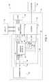
- FIG. 1is a block diagram of a communications system including a status monitoring cable of the present invention
- FIG. 2is a block diagram illustrating the example status monitoring cable of FIG. 1 in more detail
- FIG. 3is a schematic diagram of an example current detect module of the example status monitoring cable
- FIG. 4is a schematic diagram of an example connector detect module of the example status monitoring cable
- FIG. 5is a schematic diagram of an example power circuit of the example status monitoring cable
- FIG. 6is a perspective view of a first example generator and an example first cable connector of an example status monitoring system of the present invention
- FIG. 7Ais a perspective view of the first example first cable connector used with the first example generator
- FIG. 7Bis a perspective view of an example signal module that may be used by the example connectors of the first example generator;
- FIG. 8Ais a front elevation view of the first example first cable connector used with the first example generator
- FIG. 8Bis a front elevation view of an example generator connector of the first example generator
- FIG. 9is a section view of the first example first cable connector and the example generator connector of the first example generator.
- FIG. 10is a section view of the first example first cable connector engaging the example generator connector of the first example generator
- FIG. 11is a somewhat schematic view depicting the engagement of a sensor housing with a second power cable of the example status monitoring cable system
- FIG. 12is a front elevation view of a second example first cable connector that may be used with a second example generator
- FIG. 13is a side elevation view of the second example first cable connector and an example generator connector of the second example generator.
- FIG. 14is a side elevation view of the second example first cable connector engaging the example generator connector of the second example generator.
- an example communications system 20comprising a first example connector system 22 constructed in accordance with, and embodying, the principles of the present invention. At least a portion of the communications system 20 is located at a local facility 24 as will be discussed in further detail below.
- the example communications system 20comprises a power supply unit 30 configured to transfer power from a utility power source 32 to a load 34 .
- the example communications system 20further comprises a generator 36 , and the example power supply unit 30 is also configured to transfer power from the generator 36 to the load 34 .
- the power supply unit 30is also operatively connected to a head end 38 to allow data communication between the power supply unit 30 and the head end 38 .
- the example power supply unit 30comprises an uninterruptible power supply (UPS) system 40 and modem 42 .
- the example UPS system 40comprises internal batteries (not shown) that provide standby power to the load 34 when utility power from the utility 32 is unavailable or not within acceptable parameters defined by the load 34 .
- the load 34 , generator 36 , head end 38 , UPS system 40 , and modem 42all are or may be conventional components of a communications system such as conventional telephony (landline) networks, cellular telephone networks, and/or cable networks and will not be described herein beyond what is necessary for a complete understanding of the principles of the present invention.
- a communications systemsuch as conventional telephony (landline) networks, cellular telephone networks, and/or cable networks
- the first example connector system 22 , the example power supply unit 30 , the load 34 , and the generator 36are all typically arranged in relatively close proximity at the local facility 24 .
- the example utility power source 32is connected to the power supply unit 30 but typically comprises power generation, regulation, and distribution components remotely located from the local facility 24 .
- the head end 38is also typically, but not necessarily, located at a location remote from the local facility 24 .
- datais transmitted between the power supply unit 30 and the head end 38 using any available communications system such as conventional telephony (land line) systems, cellular telecommunications systems, and/or cable communications systems.
- the modem 42is provided and configured as necessary to collect, store, and format data collected at the power supply unit 30 and transmit this data to the head end 38 using one or more of the available communications systems.
- the first example connector system 22comprises a status monitoring cable system 50 , a generator connector 52 , a UPS connector 54 , and a modem connector 56 .
- the example status monitoring cable system 50comprises a sensor module 60 , a first cable connector 62 , a second cable connector 64 , a third cable connector 66 , and a jumper 68 ( FIG. 2 ).
- FIG. 2illustrates that the sensor module 60 comprises a current detect module 70 , a connector detect module 72 , and a power circuit 74 .
- the first example connector system 22further comprises a first power conductor 80 and a second power conductor 82 that extends between the first cable connector 62 and the second cable connector 64 .
- a first sensor conductor 84 and a second sensor conductor 86extend between the sensor module 60 and the first cable connector 62 .
- a generator status conductor 90 , a generator present conductor 92 , a supply conductor 94 , a common conductor 96 , and a chassis ground conductor 98extend between the sensor module 60 and the third cable connector 66 .
- the example sensor module 60monitors two characteristics or parameters associated with the example generator 36 .
- the example sensor module 60monitors both of these characteristics or parameters even if the generator 36 is not running, and the example sensor module 60 is not configured for any particular generator design and can in fact monitor these characteristics or parameters for generators of unknown make and manufacturer.
- the example current detect module 70generates a GEN_ON signal indicative of whether the generator 36 is operating by comparing signal representative of a current through the second power conductor 82 with a reference value.
- the example current detect module 70generates a signal representative of the current through the second power conductor 82 non-invasively and without making a direct electrical connection with either the first or the second power conductor 82 .
- the connector detect module 70generates a GEN_PRESENT signal indicative of whether the first cable connector 62 is connected to the generator connector 52 .
- the first cable connector 62is configured simply to detect the presence of a short circuit at the generator 36 and, if that short circuit is missing, determines that the first cable connector 62 is not connected to the generator connector 52 .
- the short circuitcan be established by modifying the generator connector 52 such that the first and second sensor conductors 84 and 86 are effectively connected together when the first cable connector 62 is connected to the generator connector 52 .
- the short circuitmay be established by bringing the first and second sensor conductors 84 and 86 into contact with a conductive portion of a given generator or a conductive member attached to that generator.
- FIG. 2shows that each of the example connectors 52 , 54 , 56 , 62 , 64 , and 66 defines a plurality of contacts.
- Table Adefines the contacts defined by the connectors 52 , 54 , 56 , 62 , 64 , and 66 forming a part of the first example cable system 22 :
- the first cable connector 62is engages the generator connector 52 such that the generator connector contacts 52 a , 52 b , 52 c , and 52 d engage or contact the first cable connector contacts 62 a , 62 b , 62 c , and 62 d , respectively, to form a low resistance electrical connection at each contact point.
- the second cable connector 64engages the UPS connector 54 such that the generator connector contacts 54 a and 54 b engage or contact the second connector contacts 64 a and 64 b , respectively, to form a low resistance electrical connection at each contact point.
- the third cable connector 66engages the modem connector 56 such that the modem connector contacts 56 a , 56 b , 56 c , 56 d , and 56 e engage or contact the third connector contacts 66 a , 66 b , 66 c , 66 d , and 66 e , respectively, to form a low resistance electrical connection at each contact point.
- the jumper 68engages the third and fourth generator contacts 52 c and 52 d to form a short circuit between these contacts 52 c and 52 d.
- FIG. 3depicts an example of a circuit that may be used to form the current detect module 70
- FIG. 4depicts an example of a circuit that may be used to form the connector detect module 72
- FIG. 5depicts an example of a circuit that may be used to form the power circuit 74 .
- a small profile integrated circuit referred to as D 1provides clamp diode connection from three channels to the +supply and circuit common, along with a high current, low clamping voltage transient voltage suppression (TVS) diode D 1 A connected across the +supply and circuit common.
- Resistors R 7 , R 8 , R 9 , R 16 , R 17 , and R 18provide current limiting for the TVS diode D 1 A in the event of transient voltage events on those lines.
- Resistors R 8 and R 9are surge rated resistors.
- Resistor R 9provides high resistance isolation to circuit common from the sense cable for the status monitor and modem circuitry.
- Circuit common of the status monitor circuitryis connected to chassis to provide a low impedance return for line currents, voltage transient currents (i.e., lightning), and radio frequency currents.
- Resistor R 17provides ground return isolation to the modem, and, with the chassis connection described above, forms a divider to provide a high attenuation path back to the modem along the circuit common.
- Resistor R 17is surge rated.
- Capacitor C 3along with resistors R 8 and R 9 , form a low pass filter at radio frequencies, forcing energy in the sense cable to be common ode with respect to the status monitor circuitry and modem circuitry.
- Component U 1is an open loop Hall effect bi-directional current sensor comprising a core large enough to accommodate the second power conductor 82 , internal core offset and circuit nulling and signal processing circuitry, and a current sense, voltage out transfer function.
- Resistor R 1 and capacitor C 1form a low pass filter to provide high attenuation to line frequency components not filtered by the Hall sensor.
- Resistor R 4provides current limiting into the operational amplifier A input from capacitor C 1 during power supply transitions.
- Resistors R 2 and R 3set the center of the operating range for the Hall sensor and track a factor of the transfer function of the Hall sensor closely for a low range of measured currents (0 to 3 A).
- Resistors R 5 and R 6 and capacitor C 2provide dynamic hysteresis.
- Resistor R 7provides isolation between the cable to the modem and the operational amplifier A.
- the output of the current detect module 70is LO if the sensed current is greater than 3 A, HI if the sensed current is less than 0.5 A, and undefined between 0.5 and 3 A.
- Resistors R 8 , R 9 , and R 10set the sense current to approximate 2 mA. Capacitor C 4 and resistors R 8 and R 9 form a low pass filter for RF, and resistor R 11 and capacitor C 5 perform the same function at line frequencies. Resistor R 12 provides current limiting from capacitor C 4 into the input of operational amplifier B during power transitions. Resistors R 13 and R 14 set the switching threshold, and resistors R 11 , R 12 , and R 15 provide short and long term hysteresis. Resistor R 16 provides isolation between the cable to the modem and the operations amplifier A. The output of the connector detect module 72 is LO if current flows through the first and second sensor conductors 84 and 86 (the jumper 68 is present) and HI if no current flows through the first and second sensor conductors 84 and 86 .
- the generator 36comprises a generator enclosure 120 ( FIG. 6 ).
- the power supply unit 30defines a power supply enclosure 122
- the sensor module 60defines a sensor housing 124 ( FIG. 11 ).
- the generator connector 52comprises a generator connector housing 126 , and the first cable connector 62 defines a first cable connector housing 128 (FIGS. 6 and 7 - 10 ).
- the generator connector housing 126is supported by the generator enclosure 120
- the first cable connector housing 128is supported by ends of the first and second power conductors 80 and 82 and the first and second sensor conductors 84 and 86 .
- the example generator connector 52 and the example first cable connector 62are identical and further constructed such that they can be detachably attached from each other in a reversed configuration. Other connector styles may be used in place of the example connectors 52 and 62 .
- the generator connector 52further comprises first and second generator signal modules 130 and 132 .
- the generator connector housing 126defines first and second generator signal sockets 134 and 136 that are adapted to detachably attach the first and second generator signal modules 130 and 132 to the connector housing 126 .
- the first cable connector 62further comprises first and second cable signal modules 140 and 142 .
- the first cable connector housing 128defines first and second generator signal sockets 144 and 146 that are adapted to detachably attach the first and second generator signal modules 130 and 132 to the connector housing 126 .
- the first and second generator contacts 52 a and 52 bare supported by the generator connector 52 and electrically connected to the generator 36 such that the output of the generator 36 is present across these contacts 52 a and 52 b .
- the third and fourth generator contacts 52 c and 52 dare supported by the first and second generator signal modules 130 and 132 .
- the jumper 68is supported by the first and second generator signal modules 130 and 132 to form a conductive path between the third and fourth generator contacts 52 c and 52 d.
- the first cable connector first and second contacts 62 a and 62 bare supported by the first cable connector 62 and electrically connected to the first and second power conductors 80 and 82 .
- the first cable connector first and second contacts 62 a and 62 bcome into contact with the first and second generator contacts 52 a and 52 b such that the output of the generator 36 is present across the second cable connector first and second contacts 64 a and 64 b .
- the first cable connector third and fourth contacts 62 c and 62 dare supported by the first and second cable signal modules 140 and 142 .
- the first cable connector third and fourth contacts 62 c and 62 dcome into contact with the third and fourth generator contacts 52 c and 52 d such current can flow between the first and second sensor conductors 84 and 86 through the jumper 68 .
- FIG. 11 of the drawingshows the physical location of the sensor module 60 .
- the sensor housing 124defines an opening 150 and is located within the power supply enclosure 122 .
- the Hall sensoris arranged such that the winding thereof is coiled around the opening 150 .
- the second power conductor 82is extended through opening 150 such that the Hall sensor generates an output signal when current flows through the second power conductor 82 .
- FIG. 11further shows a cable bundle 152 comprising the generator status conductor 90 , generator present conductor 92 , supply conductor 94 , common conductor 96 , and chassis ground conductor 98 ( FIG. 2 ).
- the cable bundle 152electrically connects the sensor module 60 to the modem 42 through the third cable connector 66 and modem connector 56 as shown in FIG. 11 .
- the generator 36comprises a generator enclosure 220 ( FIGS. 13 and 14 ).
- a generator connector 222is supported by the generator enclosure 220 .
- a first cable connector 224is supported by the ends of the first and second power conductors 80 and 82 .
- the example generator connector 222 and example first cable connector 224are conventional grounded three-prong sockets (generator connector 222 ) and plugs (first cable connector 224 ).
- first, second, and third contacts 222 a , 222 b , and 222 c of the generator connector 222are sized and dimensioned to receive first, second, and third prongs 224 a , 224 b , and 224 c , respectively, of the first cable connector 224 .
- the cable signal module 226is mounted on the first cable connector 224 that is operatively connected to the first and second sensor conductors 84 and 86 .
- the cable signal module 226comprises first and second contacts or terminals 226 a and 226 b that are connected to the first and second sensor conductors 84 and 86 .
- the cable signal module 226may be positioned such that the contacts or terminals 226 a and 226 b engage this conductive surface when the generator connector 222 is properly engaged with the first cable connector 224 to allow current to flow from the generator to the second cable connector (not shown in FIGS. 12-14 ).
- the connector detect module 72will thus determine that the connectors 222 and 224 are properly connected as generally described above. If the generator enclosure 220 is made of painted metal, a small portion of the paint can be removed to create a conductive surface.
- a jumper plate 230 made of conductive materialmay be applied to the generator enclosure.
- the cable signal module 226is positioned such that the contacts or terminals 226 a and 226 b engage this jumper plate 230 when the generator connector 222 is properly engaged with the first cable connector 224 .
- the connector detect module 72will thus determine that the connectors 222 and 224 are properly connected as generally described above.
- the contact or terminals 226 a and 226 bcan be arranged within the cable signal module 226 , and a conductive member within the cable signal module 226 may be displaced using magnetic force to complete the circuit between the terminals 226 a and 226 b .
- a strong magnetmay be located on or within the generator enclosure 220 adjacent to the generator connector 222 to cause the conductive member within the cable signal module 226 to engage the two terminals 226 a and 226 b when the generator connector 222 properly receives the first cable connector 224 .
- a magnetic sensormay be formed between the two terminals 226 a and 226 b and a magnet secured relative to the generator enclosure 220 in place of the jumper plate.
Landscapes
- Engineering & Computer Science (AREA)
- Physics & Mathematics (AREA)
- General Physics & Mathematics (AREA)
- Power Engineering (AREA)
- Business, Economics & Management (AREA)
- Emergency Management (AREA)
- Computer Networks & Wireless Communication (AREA)
- Testing Of Short-Circuits, Discontinuities, Leakage, Or Incorrect Line Connections (AREA)
Abstract
Description
| TABLE A | ||||
| Element | Reference | Diagram | ||
| Name | Character | |||
| GENERATOR CONNECTOR | ||||
| 52 | GC | |||
| 52a | G1 | |||
| 52b | G2 | |||
| 52c | G3 | |||
| 52d | ||||
| UPS CONNECTOR | ||||
| 54 | UC | |||
| 54a | U1 | |||
| 54b | ||||
| MODEM CONNECTOR | ||||
| 56 | MC | |||
| 56a | M1 | |||
| 56b | M2 | |||
| 56c | M3 | |||
| 56d | M4 | |||
| 56e | M5 | |||
| 62 | C1 | |||
| first cable connector | 62a | C1-1 | ||
| first cable connector | 62b | C1-2 | ||
| first cable connector | 62c | C1-3 | ||
| first cable connector | 62d | C1-4 | ||
| 64 | C2 | |||
| second cable connector | 64a | C2-1 | ||
| second cable connector | 64b | C2-2 | ||
| 66 | C3 | |||
| third cable connector | 66a | C3-1 | ||
| third cable connector | 66b | C3-2 | ||
| third cable connector | 66c | C3-3 | ||
| third cable connector | 66d | C3-4 | ||
| third cable connector | 66e | C3-5 | ||
Claims (21)
Priority Applications (2)
| Application Number | Priority Date | Filing Date | Title |
|---|---|---|---|
| US13/831,037US9234916B2 (en) | 2012-05-11 | 2013-03-14 | Status monitoring cables for generators |
| CA2815488ACA2815488C (en) | 2012-05-11 | 2013-05-09 | Status monitoring cables for generators |
Applications Claiming Priority (2)
| Application Number | Priority Date | Filing Date | Title |
|---|---|---|---|
| US201261646140P | 2012-05-11 | 2012-05-11 | |
| US13/831,037US9234916B2 (en) | 2012-05-11 | 2013-03-14 | Status monitoring cables for generators |
Publications (2)
| Publication Number | Publication Date |
|---|---|
| US20140028288A1 US20140028288A1 (en) | 2014-01-30 |
| US9234916B2true US9234916B2 (en) | 2016-01-12 |
Family
ID=49994251
Family Applications (1)
| Application Number | Title | Priority Date | Filing Date |
|---|---|---|---|
| US13/831,037Active2034-05-22US9234916B2 (en) | 2012-05-11 | 2013-03-14 | Status monitoring cables for generators |
Country Status (1)
| Country | Link |
|---|---|
| US (1) | US9234916B2 (en) |
Cited By (8)
| Publication number | Priority date | Publication date | Assignee | Title |
|---|---|---|---|---|
| US20150022183A1 (en)* | 2010-10-28 | 2015-01-22 | Infineon Technologies Austria Ag | Accessory Presence Detection |
| US20150280473A1 (en)* | 2014-03-26 | 2015-10-01 | Intersil Americas LLC | Battery charge system with transition control that protects adapter components when transitioning from battery mode to adapter mode |
| US9853497B2 (en) | 2011-01-22 | 2017-12-26 | Alpha Technologies Inc. | Charge equalization systems and methods for battery systems and uninterruptible power supplies |
| US10074981B2 (en) | 2015-09-13 | 2018-09-11 | Alpha Technologies Inc. | Power control systems and methods |
| US10355521B2 (en) | 2011-01-23 | 2019-07-16 | Alpha Technologies Services, Inc. | Switching systems and methods for use in uninterruptible power supplies |
| US10381867B1 (en) | 2015-10-16 | 2019-08-13 | Alpha Technologeis Services, Inc. | Ferroresonant transformer systems and methods with selectable input and output voltages for use in uninterruptible power supplies |
| US10635122B2 (en) | 2017-07-14 | 2020-04-28 | Alpha Technologies Services, Inc. | Voltage regulated AC power supply systems and methods |
| US10819144B2 (en) | 2010-02-18 | 2020-10-27 | Alpha Technologies Services, Inc. | Ferroresonant transformer for use in uninterruptible power supplies |
Families Citing this family (2)
| Publication number | Priority date | Publication date | Assignee | Title |
|---|---|---|---|---|
| US9507005B2 (en)* | 2014-03-05 | 2016-11-29 | Infineon Technologies Ag | Device and current sensor for providing information indicating a safe operation of the device of the current sensor |
| EP3678579A4 (en)* | 2017-09-08 | 2021-06-16 | Covidien LP | Energy disconnect for robotic surgical assemblies |
Citations (252)
| Publication number | Priority date | Publication date | Assignee | Title |
|---|---|---|---|---|
| US352105A (en) | 1886-11-02 | op buda-pesth | ||
| US375614A (en) | 1887-12-27 | Sparker-coil for gas-lighting | ||
| US414266A (en) | 1889-11-05 | Iron-cased induction-coil for alternating-current transfer | ||
| GB260731A (en) | 1925-09-24 | 1926-11-11 | Igranic Electric Co Ltd | Improvements in or relating to electrical transformers |
| US1718238A (en) | 1917-02-03 | 1929-06-25 | Delco Light Co | System of gas control |
| US1950396A (en) | 1932-12-12 | 1934-03-13 | Charles P Boucher | Electric luminescent tube system and apparatus |
| FR762789A (en) | 1932-10-19 | 1934-04-18 | Siemens Ag | Magnetic body, especially for high frequency applications |
| US2007415A (en) | 1927-10-25 | 1935-07-09 | Mary C Dunn | Emergency lighting and power unit |
| US2014101A (en) | 1930-10-22 | 1935-09-10 | Joseph P Bryan | Emergency generating set |
| US2037183A (en) | 1935-01-30 | 1936-04-14 | Bell Telephone Labor Inc | Carrier line power supply |
| US2036994A (en) | 1932-08-22 | 1936-04-14 | Detracolor Ltd | Photographic film and method of treating same |
| US2085072A (en) | 1934-06-14 | 1937-06-29 | Westinghouse Electric & Mfg Co | Small electric power plant |
| US2165969A (en) | 1938-06-17 | 1939-07-11 | Reuben L Humbert | Prime mover dynamo plant |
| FR861215A (en) | 1939-01-24 | 1941-02-04 | Special self-regulating electric transformer, for the simultaneous supply of several light emitters | |
| US2240123A (en) | 1933-09-16 | 1941-04-29 | Rca Corp | Power supply system |
| US2302192A (en) | 1940-03-29 | 1942-11-17 | Es B Es Co Ltd | Emergency power system |
| US2352073A (en) | 1941-07-14 | 1944-06-20 | Boucher Inv S Ltd | Luminescent tube system and apparatus |
| US2427678A (en) | 1945-08-25 | 1947-09-23 | Werner E F Laging | Auxiliary electrical generating and control system |
| US2444794A (en) | 1945-02-13 | 1948-07-06 | Gen Electric | Voltage stabilizing system |
| US2512976A (en) | 1948-01-14 | 1950-06-27 | Modern Controls Inc | Means for producing constant current from constant potential |
| US2688704A (en) | 1953-05-13 | 1954-09-07 | Us Motors Corp | Motor and engine driven electric generating assemblage |
| US2856543A (en) | 1956-12-19 | 1958-10-14 | Porter Co H K | Means for maintaining standby power source in immediate readiness |
| US2860748A (en) | 1955-09-26 | 1958-11-18 | Singer Mfg Co | Electrically controlled power transmitters |
| US2920211A (en) | 1955-03-30 | 1960-01-05 | Kokusai Electric Co Ltd | System for generating electric power without interruption |
| US2996656A (en) | 1959-02-02 | 1961-08-15 | Basic Products Corp | Voltage regulating apparatus |
| US3022458A (en) | 1959-05-29 | 1962-02-20 | Joseph G Sola | Voltage regulating apparatus |
| US3064195A (en) | 1960-05-05 | 1962-11-13 | Benco Television Associates Lt | Signal distribution system |
| US3221172A (en) | 1962-08-29 | 1965-11-30 | John G Stevens | No-break power supply |
| US3283165A (en) | 1963-08-22 | 1966-11-01 | Dynamics Corp America | No break power system |
| US3293445A (en) | 1962-10-01 | 1966-12-20 | Rca Corp | Power supply circuit |
| US3305762A (en) | 1962-10-17 | 1967-02-21 | Ideal Electric And Mfg Company | Method of control of electric power |
| US3304599A (en) | 1965-03-30 | 1967-02-21 | Teletype Corp | Method of manufacturing an electromagnet having a u-shaped core |
| US3339080A (en) | 1964-06-24 | 1967-08-29 | Lorain Prod Corp | Dc-ac or ac-dc converter |
| US3345517A (en) | 1964-02-14 | 1967-10-03 | Dynamics Corp America | Uninterrupted power supply |
| US3348060A (en) | 1964-01-14 | 1967-10-17 | Lorain Prod Corp | Continuously-operatingstandby powersupply and battery-charging apparatus and method |
| US3389329A (en) | 1965-06-22 | 1968-06-18 | Transformer Engineers Inc | Constant output voltage transformer |
| US3435358A (en) | 1966-06-08 | 1969-03-25 | Anaconda Electronics Co | Cable television amplifier powering |
| US3458710A (en) | 1966-04-06 | 1969-07-29 | Automatic Power Inc | Emergency power system |
| US3521152A (en) | 1967-08-28 | 1970-07-21 | Acme Electric Corp | Constant voltage transformer with core gap at primary end |
| US3525035A (en) | 1968-09-30 | 1970-08-18 | Bell Telephone Labor Inc | Closed loop ferroresonant voltage regulator which simulates core saturation |
| US3525078A (en) | 1965-12-30 | 1970-08-18 | Londex Ltd | Apparatus for transmitting data over electric power supply network |
| US3546571A (en) | 1968-06-21 | 1970-12-08 | Varo | Constant voltage ferroresonant transformer utilizing unequal area core structure |
| US3590362A (en) | 1969-09-24 | 1971-06-29 | Bell Telephone Labor Inc | Dc to dc converter circuit with load voltage regulation utilizing a controlled simulated saturating core |
| US3636368A (en) | 1970-06-29 | 1972-01-18 | Onan Eastern Corp | Transfer switch and generator control means and new and improved method of operation thereof |
| US3678284A (en) | 1968-08-27 | 1972-07-18 | Charles Michael Dansey Peters | Energy supply apparatus and method for a building |
| US3678377A (en) | 1969-12-11 | 1972-07-18 | Compteurs Comp D | Apparatus for detecting saturation periods of a transformer |
| US3686561A (en) | 1971-04-23 | 1972-08-22 | Westinghouse Electric Corp | Regulating and filtering transformer having a magnetic core constructed to facilitate adjustment of non-magnetic gaps therein |
| US3691393A (en) | 1970-04-01 | 1972-09-12 | Christos Papachristou | Automatic starter for internal combustion machines |
| US3737858A (en) | 1971-07-13 | 1973-06-05 | Advanced Research Corp | Versatile telemetering system |
| US3742251A (en) | 1969-02-13 | 1973-06-26 | Westinghouse Electric Corp | Power regulation system |
| US3823358A (en) | 1973-06-18 | 1974-07-09 | United Aircraft Corp | Battery peaking unit for fuel cell power plants |
| US3859589A (en) | 1973-06-05 | 1975-01-07 | Charles G Rush | Electric generation apparatus |
| US3873846A (en) | 1972-09-07 | 1975-03-25 | Sony Corp | Power supply system |
| US3909560A (en) | 1973-03-05 | 1975-09-30 | Kabel Metallwerke Ghh | Method and system for providing power to booster amplifiers in h.f. cable network |
| US3916295A (en) | 1974-07-15 | 1975-10-28 | North Electric Co | Ferroresonant voltage regulator stabilized for light load conditions |
| US3938033A (en) | 1974-05-22 | 1976-02-10 | Sola Basic Industries, Inc. | Ferroresonant transformer regulator |
| US3943447A (en) | 1973-10-10 | 1976-03-09 | Comsonics, Inc. | Method and apparatus for bi-directional communication via existing CATV system |
| US4004110A (en) | 1975-10-07 | 1977-01-18 | Westinghouse Electric Corporation | Power supply for power line carrier communication systems |
| US4010381A (en) | 1975-04-24 | 1977-03-01 | Bell Telephone Laboratories, Incorporated | No-break ac power supply |
| DE2602789A1 (en) | 1976-01-26 | 1977-07-28 | Elektr Strassenverkehr Ges | Battery charger for electric cars - has bridge circuit with non-controlled rectifiers connected to AC voltage source |
| US4060844A (en) | 1976-02-17 | 1977-11-29 | I-T-E Imperial Corporation | Solid state tripping circuit |
| DE2809514A1 (en) | 1977-03-08 | 1978-09-14 | S E I Electronics | ACCUMULATOR CHARGER |
| US4122382A (en) | 1977-04-20 | 1978-10-24 | Combustion Engineering, Inc. | Load-responsive treater controller |
| US4130790A (en) | 1977-04-25 | 1978-12-19 | Hobart Brothers Company | Ferroresonant transformer power supply |
| US4170761A (en) | 1977-03-28 | 1979-10-09 | Siemens Aktiengesellschaft | Remotely powered intermediate amplifier for communications transmission |
| US4198624A (en) | 1977-05-02 | 1980-04-15 | Hochiki Corporation | Alarm system |
| JPS5532133Y2 (en) | 1975-02-12 | 1980-07-31 | ||
| US4251736A (en) | 1979-07-23 | 1981-02-17 | United Technologies Corporation | Method for controlling power flow between an electrochemical cell and a power grid |
| US4262245A (en) | 1979-01-30 | 1981-04-14 | Rca Corp. | High frequency ferroresonant transformer |
| US4270080A (en) | 1978-12-14 | 1981-05-26 | Sun Electric Corporation | Automatic battery charge apparatus and method |
| US4277692A (en) | 1979-06-04 | 1981-07-07 | Tab Products Company | Continuous power source with bi-directional converter |
| US4295053A (en) | 1979-10-23 | 1981-10-13 | Westinghouse Electric Corp. | Electric control system with mechanical interlock |
| US4295054A (en) | 1979-10-23 | 1981-10-13 | Westinghouse Electric Corp. | Electric control system with rotary mechanical interlock and timing mechanism |
| JPS56155420U (en) | 1980-04-20 | 1981-11-20 | ||
| GB2005118B (en) | 1977-07-07 | 1982-01-06 | Electricity Council | Generating signal currents in ac power lines |
| US4313060A (en) | 1980-02-15 | 1982-01-26 | Bell Telephone Laboratories, Incorporated | Uninterruptible power supply with load regulation of standby voltage source |
| US4353014A (en) | 1981-04-20 | 1982-10-05 | Rca Corporation | Television receiver ferroresonant load power supply with reduced saturable reactor circulating current |
| US4366389A (en) | 1981-07-13 | 1982-12-28 | Reliance Electric Company | Continuously operating standby A-C power system |
| US4366390A (en) | 1980-07-16 | 1982-12-28 | Rathmann Soren H | Emergency power unit |
| US4385263A (en) | 1980-08-04 | 1983-05-24 | Rca Corporation | Television receiver, push-pull inverter, ferroresonant transformer power supply synchronized with horizontal deflection |
| US4400625A (en) | 1981-11-30 | 1983-08-23 | Reliance Electric Company | Standby A-C power system with transfer compensation circuitry |
| US4400624A (en) | 1982-04-29 | 1983-08-23 | Bell Telephone Laboratories, Incorporated | Uninterruptible power supplies |
| DE3321649A1 (en) | 1982-06-19 | 1983-12-22 | Mitsubishi Denki K.K., Tokyo | Diagnostic device for vehicle batteries |
| US4423379A (en) | 1981-03-31 | 1983-12-27 | Sun Electric Corporation | Battery testing techniques |
| US4446458A (en) | 1981-09-14 | 1984-05-01 | Donald Cook | Monitoring and control system |
| US4460834A (en) | 1983-08-29 | 1984-07-17 | Power Group International Corp. | Uninterruptible power system |
| US4466041A (en) | 1983-02-01 | 1984-08-14 | Storage Technology Corporation | Fault protection system for power supplies that use ferro-resonant transformers |
| US4472641A (en) | 1983-01-28 | 1984-09-18 | Westinghouse Electric Corp. | Power supply apparatus |
| US4475047A (en) | 1982-04-29 | 1984-10-02 | At&T Bell Laboratories | Uninterruptible power supplies |
| US4477799A (en) | 1981-12-07 | 1984-10-16 | General Instrument Corporation | Security apparatus with alarm search and verification capability |
| US4510401A (en) | 1981-09-17 | 1985-04-09 | Etablissements-Pierre Fontaine | Processes and devices for providing a load with an electric AC supply without discontinuity of the AC signal |
| WO1985001842A1 (en) | 1983-10-11 | 1985-04-25 | Exide Electronics International Corp. | Uninterruptible power supply and line conditioner |
| GB2120474B (en) | 1982-05-11 | 1985-10-23 | Harmer & Simmons Ltd | Standby power supply system |
| GB2137033B (en) | 1983-03-24 | 1986-05-08 | Nishimu Denshi Kogyo Kk | Uninterruptible ac power supply |
| US4604530A (en) | 1983-08-16 | 1986-08-05 | Kabushiki Kaisha Meidensha | Power supply equipment backup system for interruption of service |
| US4616305A (en) | 1985-02-11 | 1986-10-07 | Eaton Corporation | AC/DC power MOSFET reversing H-drive system |
| US4628426A (en) | 1985-10-31 | 1986-12-09 | General Electric Company | Dual output DC-DC converter with independently controllable output voltages |
| US4631471A (en) | 1985-03-25 | 1986-12-23 | At&T Bell Laboratories | Inductor apparatus for application of ferroresonant regulators |
| US4656412A (en) | 1985-07-08 | 1987-04-07 | California Institute Of Technology | Ferroresonant flux coupled battery charger |
| US4670702A (en) | 1985-07-16 | 1987-06-02 | Sanyo Electric Co., Ltd. | Controller for fuel cell power system |
| US4673825A (en) | 1985-02-15 | 1987-06-16 | Exide Electronics Corporation | Uninterruptible power supply with isolated bypass winding |
| US4686375A (en) | 1986-03-05 | 1987-08-11 | Power Group International Corp. | Uninterruptible power supply cogeneration system |
| US4697134A (en) | 1986-07-31 | 1987-09-29 | Commonwealth Edison Company | Apparatus and method for measuring battery condition |
| US4700122A (en) | 1985-10-28 | 1987-10-13 | The United States Of America As Represented By The Secretary Of The Air Force | Power supply filtering with rechargeable battery element |
| US4709318A (en) | 1986-10-22 | 1987-11-24 | Liebert Corporation | UPS apparatus with control protocols |
| US4719550A (en) | 1986-09-11 | 1988-01-12 | Liebert Corporation | Uninterruptible power supply with energy conversion and enhancement |
| US4719427A (en) | 1983-06-20 | 1988-01-12 | Mitsubishi Denki Kabushiki Kaisha | Vehicle battery diagnostic device |
| US4724478A (en) | 1984-05-30 | 1988-02-02 | Kabushiki Kaisha Toshiba | Cable television communication system with passive sensor signal path and a subscriber power supply source |
| US4724290A (en) | 1984-04-25 | 1988-02-09 | Campbell Mason M | Microwave popcorn popper |
| US4730242A (en) | 1986-09-25 | 1988-03-08 | Wisconsin Alumni Research Foundation | Static power conversion and apparatus having essentially zero switching losses |
| US4733223A (en) | 1987-03-26 | 1988-03-22 | Gilbert William C | Apparatus for monitoring a communications system |
| US4740739A (en) | 1987-02-10 | 1988-04-26 | Premier Engineered Products Corporation | Battery charging apparatus and method |
| US4745299A (en) | 1986-04-17 | 1988-05-17 | American Telephone And Telegraph Company, At&T Bell Laboratories | Off-line switcher with battery reserve |
| US4748342A (en) | 1985-12-18 | 1988-05-31 | U.S. Philips Corporation | Power supply circuit |
| US4748341A (en) | 1987-03-24 | 1988-05-31 | Rte Deltec Corporation | Uninterruptible power supply |
| US4763014A (en) | 1987-09-21 | 1988-08-09 | American Telephone And Telegraph Company, At&T Bell Laboratories | Backup protection switch to prevent reverse power flow in a UPS |
| US4775800A (en) | 1983-12-30 | 1988-10-04 | Westinghouse Elctric Corp. | Power-supply apparatus |
| US4791542A (en) | 1987-08-03 | 1988-12-13 | Rfl Industries, Inc. | Ferroresonant power supply and method |
| US4829225A (en) | 1985-10-23 | 1989-05-09 | Electronic Power Devices, Corp. | Rapid battery charger, discharger and conditioner |
| US4860185A (en) | 1987-08-21 | 1989-08-22 | Electronic Research Group, Inc. | Integrated uninterruptible power supply for personal computers |
| US4864483A (en) | 1986-09-25 | 1989-09-05 | Wisconsin Alumni Research Foundation | Static power conversion method and apparatus having essentially zero switching losses and clamped voltage levels |
| US4882717A (en) | 1987-09-21 | 1989-11-21 | Seiko Epson Corporation | Charging circuit for an analog electronic timepiece |
| US4885474A (en)* | 1989-03-15 | 1989-12-05 | Dual Lite, Inc. | Connector assembly for plug-in energization and battery activation of an associated electrical apparatus |
| US4890213A (en) | 1987-05-28 | 1989-12-26 | Kabushiki Kaisha Toshiba | Power converter device having starting circuits and a method for starting the power converter device |
| GB2185326B (en) | 1986-01-14 | 1990-03-14 | Eikoh Giken Co Ltd | A circuit arrangement for judging the lifetime of a battery in a no-break power supply system |
| US4916329A (en) | 1987-10-05 | 1990-04-10 | Square D Company | Uninterruptible power supply |
| US4920475A (en) | 1988-03-07 | 1990-04-24 | California Institute Of Technology | Integrated traction inverter and battery charger apparatus |
| US4922125A (en)* | 1988-03-17 | 1990-05-01 | International Business Machines Corporation | System cable assembly and component packaging |
| US4926084A (en) | 1988-05-06 | 1990-05-15 | Canon Kabushiki Kaisha | Driving apparatus for a vibration wave motor |
| US4943763A (en) | 1988-09-08 | 1990-07-24 | Albar, Inc. | Ferroresonant transformer with dual outputs |
| US4952834A (en) | 1988-03-14 | 1990-08-28 | Olympus Optical Co., Ltd. | Circuitry for driving ultrasonic motor |
| US4954741A (en) | 1987-01-19 | 1990-09-04 | Canon Kabushiki Kaisha | Control circuit for a vibration wave motor |
| US4975649A (en) | 1989-12-18 | 1990-12-04 | Albar, Inc. | Method and apparatus for sensing loss of regulation in a ferroresonant transformer |
| US4988283A (en) | 1988-01-14 | 1991-01-29 | Fuji Electric Co., Ltd. | Fuel cell power generating apparatus and method for controlling the apparatus |
| US5010469A (en) | 1990-05-09 | 1991-04-23 | Albar | Uninterruptible power supply with dual level voltage input |
| US5017800A (en) | 1989-09-29 | 1991-05-21 | Wisconsin Alumni Research Foundation | AC to DC to AC power conversion apparatus with few active switches and input and output control |
| US5027264A (en) | 1989-09-29 | 1991-06-25 | Wisconsin Alumni Research Foundation | Power conversion apparatus for DC/DC conversion using dual active bridges |
| US5029285A (en) | 1990-04-20 | 1991-07-02 | Albar, Inc. | Power back feed protection device |
| US5057698A (en) | 1989-11-13 | 1991-10-15 | Exide Electronics | Shunt circuit for reducing audible noise at low loading conditions of a power supply employing a high frequency resonant converter |
| US5099410A (en) | 1990-11-13 | 1992-03-24 | Wisconsin Alumni Research Foundation | Single phase ac power conversion apparatus |
| US5137020A (en) | 1990-11-29 | 1992-08-11 | Medtronic, Inc. | Battery impedance measurement apparatus |
| US5148043A (en) | 1989-07-25 | 1992-09-15 | Kabushiki Kaisha Toshiba | Uninterruptible power supply diagnosing remaining battery capacity during normal external power source operation |
| US5154986A (en) | 1991-03-22 | 1992-10-13 | Yamaha Hatsudoki Kabushiki Kaisha | Shut-off device for fuel cell system |
| US5168205A (en) | 1990-04-04 | 1992-12-01 | Hein-Werner Corporation | Method and apparatus for charging a battery in high amp and automatic charging modes |
| US5172009A (en) | 1991-02-25 | 1992-12-15 | Regents Of The University Of Minnesota | Standby power supply with load-current harmonics neutralizer |
| US5185536A (en) | 1991-09-27 | 1993-02-09 | Exide Electronics | Uninterruptible power supply having improved battery charger |
| US5193067A (en) | 1988-12-05 | 1993-03-09 | Nippondenso Co., Ltd. | Battery condition detecton apparatus |
| US5198970A (en) | 1988-04-27 | 1993-03-30 | Mitsubishi Denki Kabushiki Kaisha | A.C. power supply apparatus |
| US5198698A (en) | 1991-02-11 | 1993-03-30 | Best Power Technology, Inc. | Auxiliary power supply system for providing dc power on demand |
| US5200586A (en) | 1991-07-31 | 1993-04-06 | Westinghouse Electric Corp. | Five gear isolating mechanism for bypass isolation switches |
| US5200643A (en) | 1989-02-21 | 1993-04-06 | Westinghouse Electric Corp. | Parallel electric power supplies with current sharing and redundancy |
| US5220597A (en) | 1990-04-11 | 1993-06-15 | Kabushiki Kaisha Toshiba | Dialing apparatus for power failure extension telephone set of key telephone system |
| US5224025A (en) | 1992-04-21 | 1993-06-29 | Wisconsin Alumni Research Foundation | Forward converter with two active switches and unity power factor capability |
| CA2086897A1 (en) | 1992-01-13 | 1993-07-14 | Howard H. Bobry | Toroidal transformer and method for making |
| US5229650A (en) | 1990-11-07 | 1993-07-20 | Yuasa Battery Company Limited | Uniterruptible power system |
| US5237208A (en) | 1988-10-25 | 1993-08-17 | Nishimu Electronics Industries Co., Ltd. | Apparatus for parallel operation of triport uninterruptable power source devices |
| US5241591A (en) | 1990-06-01 | 1993-08-31 | Rohm Co., Ltd. | Telephone system having a dial data changeover switch |
| US5281919A (en) | 1988-10-14 | 1994-01-25 | Alliedsignal Inc. | Automotive battery status monitor |
| US5302858A (en) | 1991-12-11 | 1994-04-12 | Best Power Technology, Incorporated | Method and apparatus for providing battery charging in a backup power system |
| US5402053A (en) | 1993-08-26 | 1995-03-28 | Wisconsin Alumni Research Foundation | Single phase to three phase converter capable of variable speed motor operation |
| US5410720A (en) | 1992-10-28 | 1995-04-25 | Alpha Technologies | Apparatus and methods for generating an AC power signal for cable TV distribution systems |
| US5440179A (en) | 1993-04-26 | 1995-08-08 | Severinsky; Alex J. | UPS with bi-directional power flow |
| US5457377A (en) | 1992-10-01 | 1995-10-10 | Fps Power Systems Oy Ab | Method of monitoring the internal impedance of an accumulator battery in an uninterruptible power supply, and an uninterruptible power supply |
| US5467384A (en) | 1993-05-28 | 1995-11-14 | U S West Advanced Technologies, Inc. | Method and apparatus for providing power to a coaxial cable network |
| AU2029495A (en) | 1994-06-02 | 1995-12-14 | Alpha Technologies, Inc. | Cogeneration power system |
| US5483463A (en) | 1993-07-30 | 1996-01-09 | Controlled Power Company | Uninterruptible power supply (UPS) and method |
| US5579197A (en) | 1995-01-24 | 1996-11-26 | Best Power Technology, Incorporated | Backup power system and method |
| US5581246A (en) | 1990-02-01 | 1996-12-03 | Gulton Industries, Inc. | Multiple device control system |
| US5602462A (en) | 1995-02-21 | 1997-02-11 | Best Power Technology, Incorporated | Uninterruptible power system |
| US5610451A (en) | 1995-11-30 | 1997-03-11 | Magnum Power Plc | Uninterruptible power supply with power factor correction |
| US5635773A (en) | 1995-08-23 | 1997-06-03 | Litton Systems, Inc. | High efficiency, no dropout uninterruptable power supply |
| US5638244A (en) | 1993-10-29 | 1997-06-10 | Alpha Technologies, Inc. | Apparatus and methods for generating uninterruptible AC power signals |
| US5734831A (en) | 1996-04-26 | 1998-03-31 | Sun Microsystems, Inc. | System for configuring and remotely administering a unix computer over a network |
| US5739595A (en) | 1992-10-28 | 1998-04-14 | Alpha Technologies, Inc. | Apparatus and methods for generating an AC power signal for cable tv distribution systems |
| US5745356A (en) | 1996-06-25 | 1998-04-28 | Exide Electronics Corporation | Independent load sharing of AC power systems connected in parallel |
| US5747887A (en) | 1991-04-25 | 1998-05-05 | Kundenko Co., Ltd. | Multi-function electric power conversion system |
| US5747888A (en) | 1995-10-17 | 1998-05-05 | Zilberberg; David | Back up system for the supply of voltage in television cable systems |
| US5760495A (en) | 1995-02-22 | 1998-06-02 | Alpha Technologies, Inc. | Inverter/charger circuit for uninterruptible power supplies |
| US5768117A (en) | 1993-12-27 | 1998-06-16 | Hitachi, Ltd. | Power supply system for supplying electric power to a load through plural converters |
| US5783932A (en) | 1995-03-23 | 1998-07-21 | Hitachi, Ltd. | Power generation plant and control apparatus therefor |
| US5790391A (en) | 1996-11-29 | 1998-08-04 | General Signal Corporation | Standby power system |
| US5844327A (en) | 1996-08-21 | 1998-12-01 | Antec Corporation | Apparatus and method for optimizing power distributed in a broadband signal system |
| US5880536A (en) | 1997-05-14 | 1999-03-09 | Io Limited Partnership, Llp | Customer side power management system including auxiliary fuel cell for reducing potential peak load upon utilities and providing electric power for auxiliary equipment |
| US5892431A (en) | 1997-05-20 | 1999-04-06 | Alpha Technologies, Inc. | Power multiplexer for broadband communications systems |
| US5897766A (en) | 1994-11-02 | 1999-04-27 | Toyota Jidosa Kabushiki Kaisha | Apparatus for detecting carbon monoxide, organic compound, and lower alcohol |
| US5901057A (en) | 1992-06-10 | 1999-05-04 | Digital Equipment Corporation | Uninterruptible power supply with fault tolerance in a high voltage environment |
| US5925476A (en) | 1996-09-06 | 1999-07-20 | Toyota Jidosha Kabushiki Kaisha | Fuel-cells generator system and method of generating electricity from fuel cells |
| US5961604A (en) | 1997-06-03 | 1999-10-05 | Alpha Technologies, Inc. | Status monitoring systems for cable television signal distribution networks |
| US5982652A (en) | 1998-07-14 | 1999-11-09 | American Power Conversion | Method and apparatus for providing uninterruptible power using a power controller and a redundant power controller |
| US5982645A (en) | 1992-08-25 | 1999-11-09 | Square D Company | Power conversion and distribution system |
| US5994793A (en) | 1998-05-11 | 1999-11-30 | Multipower, Inc. | Uninterruptible power supply with plurality of inverters |
| US5994794A (en) | 1997-05-09 | 1999-11-30 | Active Power, Inc. | Methods and apparatus for providing protection to batteries in an uninterruptible power supply |
| US6011324A (en) | 1995-10-14 | 2000-01-04 | Aeg Energietechnik Gmbh | Arrangement for ensuring uninterrupted current supply to an electrical consumer |
| US6014015A (en) | 1997-08-08 | 2000-01-11 | Alpha Technologies, Inc. | Electrical generator employing rotary engine |
| US6028414A (en) | 1997-01-29 | 2000-02-22 | H Power Enterprises Of Canada Inc. | Fuel cell stand-by energy supply system |
| US6069412A (en) | 1993-03-29 | 2000-05-30 | Powerware Corporation | Power factor corrected UPS with improved connection of battery to neutral |
| US6100665A (en) | 1999-05-25 | 2000-08-08 | Alderman; Robert J. | Electrical power system with relatively-low voltage input and method |
| JP2000350381A (en) | 1999-05-31 | 2000-12-15 | Itochu Cable System Kk | Power source wave-form shaping device |
| US6198178B1 (en) | 1999-12-21 | 2001-03-06 | International Power Systems, Inc. | Step wave power converter |
| US6212081B1 (en) | 1999-05-14 | 2001-04-03 | Nihon Protector Co., Ltd. | Uninterruptible duplexed power supply system |
| US6218744B1 (en) | 1999-03-22 | 2001-04-17 | Powerware Corporation | Uninterruptible power supply and ferroresonant transformer for use therewith |
| JP2001190035A (en) | 1999-10-15 | 2001-07-10 | Alpha Technologies Inc | Multiple output uniterrupted power supply for communications system |
| US6288456B1 (en) | 1998-05-19 | 2001-09-11 | Sure Power Corporation | Power system |
| US6295215B1 (en) | 2000-04-06 | 2001-09-25 | Powerware Corporation | AC power supply apparatus with economy mode and methods of operation thereof |
| US6348782B1 (en) | 1998-10-02 | 2002-02-19 | Powerware Corporation | Uninterruptible power supply systems, voltage regulators and operating methods employing controlled ferroresonant transformer circuits |
| US6456036B1 (en) | 2000-09-29 | 2002-09-24 | Motorola Inc. | Battery having a network communication interface |
| US6465910B2 (en) | 2001-02-13 | 2002-10-15 | Utc Fuel Cells, Llc | System for providing assured power to a critical load |
| RU2191459C1 (en) | 2001-09-20 | 2002-10-20 | Джинчарадзе Автандил Вахтангович | Multimode power source |
| US6486399B1 (en) | 2001-05-08 | 2002-11-26 | Powerware Corporation | Pole mount cabinet and method for assembling the same |
| US6602627B2 (en) | 2000-03-20 | 2003-08-05 | Alpha Technologies, Inc. | Uninterruptible power supplies using fuel cells |
| RU2221320C2 (en) | 2001-12-18 | 2004-01-10 | Никитин Игорь Евгеньевич | Multichannel no-break regulated power supply |
| US6768722B1 (en) | 2000-06-23 | 2004-07-27 | At&T Corp. | Systems and methods for managing multiple communications |
| US6841971B1 (en) | 2002-05-29 | 2005-01-11 | Alpha Technologies, Inc. | Charge balancing systems and methods |
| US20050096772A1 (en) | 2003-10-31 | 2005-05-05 | Cox David N. | Transformer performance prediction |
| US6906933B2 (en) | 2002-11-01 | 2005-06-14 | Powerware Corporation | Power supply apparatus and methods with power-factor correcting bypass mode |
| US6933626B2 (en) | 2001-04-24 | 2005-08-23 | Alphatec Ltd. | Ferroelectric transformer-free uninterruptible power supply (UPS) systems and methods for communications signal distribution systems |
| JP2005295776A (en) | 2004-04-06 | 2005-10-20 | Fuji Electric Fa Components & Systems Co Ltd | PWM inverter control method |
| US20050258927A1 (en) | 2002-07-17 | 2005-11-24 | Weimin Lu | Simplified harmonic-free constant-voltage transformer |
| US7040920B2 (en) | 2003-06-06 | 2006-05-09 | Alpha Technologies, Inc. | Connection systems and methods for utility meters |
| KR20070108759A (en) | 2006-05-08 | 2007-11-13 | 삼성에스디아이 주식회사 | Logistics management system for battery production using wireless communication recognition chip and secondary battery with wireless communication recognition chip |
| US20070262650A1 (en) | 2006-05-09 | 2007-11-15 | Delta Electronics, Inc. | Uninterruptible power supply with low power loss |
| US20080024268A1 (en) | 2006-07-14 | 2008-01-31 | Wong Hong W | Component authentication for computer systems |
| US7449798B2 (en) | 2002-08-01 | 2008-11-11 | I-Hits Laboratory | Co-generated power supply system |
| US20080278006A1 (en) | 1994-03-03 | 2008-11-13 | American Power Conversion Corporation | Battery communication system |
| US20090076661A1 (en)* | 2007-07-25 | 2009-03-19 | Ken Pearson | Apparatus, system, and method to manage the generation and use of hybrid electric power |
| US7543328B2 (en) | 2001-05-08 | 2009-06-02 | At&T Corp. | Method and system for providing an efficient use of broadband network resources |
| CA2713017A1 (en) | 2008-01-23 | 2009-07-30 | Alpha Technologies, Inc. | Simplified maximum power point control utilizing the pv array voltage at the maximum power point |
| US20090196082A1 (en) | 2007-12-12 | 2009-08-06 | Mazumder Sudip K | Multiphase Converter Apparatus and Method |
| US20090240377A1 (en)* | 2007-09-19 | 2009-09-24 | Briggs And Stratton Corporation | Power monitoring system |
| TW200941897A (en) | 2008-02-07 | 2009-10-01 | American Power Conv Corp | Systems and methods for uninterruptible power supply control |
| JP2010136547A (en) | 2008-12-05 | 2010-06-17 | Daihen Corp | Inverter control circuit, and system-linked inverter system having the inverter control circuit |
| US20100161259A1 (en) | 2007-08-29 | 2010-06-24 | Powertron Engineering Co., Ltd. | Aging status diagnostic apparatus for power conversion system, and method their of |
| US20100250192A1 (en) | 2009-03-27 | 2010-09-30 | American Power Conversion Corporation | System and method for estimating an efficiency of a power device |
| CA2760581A1 (en) | 2009-05-01 | 2010-11-04 | Alpha Technologies, Inc. | Solar power systems optimized for use in cold weather conditions |
| JP2010252573A (en) | 2009-04-17 | 2010-11-04 | Toshiba Corp | Inverter temperature detection method and control method, and variable magnetic flux motor control device |
| US7835379B2 (en) | 2000-09-22 | 2010-11-16 | Ciena Corporation | Network architecture for intelligent network elements |
| US20100324548A1 (en)* | 2007-02-25 | 2010-12-23 | Baylis Medical Company Inc. | Methods for control of energy delivery to multiple energy delivery devices |
| US20100328851A1 (en) | 2007-12-28 | 2010-12-30 | Tomasz Jurek | Switchboard with ups and horizontal busbars |
| GB2475612A (en) | 2009-11-23 | 2011-05-25 | Chih-Ang Yao | Anti-fake battery pack with cells having inner and outer identifiers |
| US20110238345A1 (en)* | 2008-02-20 | 2011-09-29 | Verigy (Singapore) Pte. Ltd | System, method and computer program for detecting an electrostatic discharge event |
| US8074888B2 (en) | 2008-03-07 | 2011-12-13 | Compagnie Industrielle et Financiere D'Ingenierie “Ingenico” | Terminal, method of checking conformity of at least one removable battery of an electronic payment terminal, and the corresponding removable battery and computer program product |
| WO2011103131A3 (en) | 2010-02-18 | 2011-12-29 | Alpha Technologies Inc. | Ferroresonant transformer for use in uninterruptible power supplies |
| CN101330686B (en) | 2008-06-27 | 2012-03-14 | 潘良春 | Method and system for synthesis false-proof of mobile phone battery |
| US20120091811A1 (en) | 2010-10-18 | 2012-04-19 | Alpha Technologies, Inc. | Uninterruptible Power Supply Systems and Methods for Communications Systems |
| WO2012099911A1 (en) | 2011-01-23 | 2012-07-26 | Alpha Technologies Inc. | Uninterruptible power supplies for use in a distributed network |
| WO2012112252A2 (en) | 2011-01-22 | 2012-08-23 | Alpha Technologies Inc. | Charge equalization systems and methods |
| US20120217808A1 (en) | 2011-01-23 | 2012-08-30 | Alpha Technologies Inc. | Switching systems and methods for use in uninterruptible power supplies |
| US20120217800A1 (en) | 2011-02-11 | 2012-08-30 | Alpha Technologies Inc. | Solar power systems optimized for use in communications networks |
| US8344685B2 (en) | 2004-08-20 | 2013-01-01 | Midtronics, Inc. | System for automatically gathering battery information |
| US8616457B2 (en) | 2010-11-22 | 2013-12-31 | Mark Stanley Krawczewicz | RFID display label for battery packs |
| JP5482053B2 (en) | 2009-09-25 | 2014-04-23 | 大陽日酸株式会社 | Forming method of film |
| JP5650417B2 (en) | 2010-03-11 | 2015-01-07 | 株式会社東洋工芸 | Chair |
- 2013
- 2013-03-14USUS13/831,037patent/US9234916B2/enactiveActive
Patent Citations (277)
| Publication number | Priority date | Publication date | Assignee | Title |
|---|---|---|---|---|
| US375614A (en) | 1887-12-27 | Sparker-coil for gas-lighting | ||
| US414266A (en) | 1889-11-05 | Iron-cased induction-coil for alternating-current transfer | ||
| US352105A (en) | 1886-11-02 | op buda-pesth | ||
| US1718238A (en) | 1917-02-03 | 1929-06-25 | Delco Light Co | System of gas control |
| GB260731A (en) | 1925-09-24 | 1926-11-11 | Igranic Electric Co Ltd | Improvements in or relating to electrical transformers |
| US2007415A (en) | 1927-10-25 | 1935-07-09 | Mary C Dunn | Emergency lighting and power unit |
| US2014101A (en) | 1930-10-22 | 1935-09-10 | Joseph P Bryan | Emergency generating set |
| US2036994A (en) | 1932-08-22 | 1936-04-14 | Detracolor Ltd | Photographic film and method of treating same |
| FR762789A (en) | 1932-10-19 | 1934-04-18 | Siemens Ag | Magnetic body, especially for high frequency applications |
| US1950396A (en) | 1932-12-12 | 1934-03-13 | Charles P Boucher | Electric luminescent tube system and apparatus |
| US2240123A (en) | 1933-09-16 | 1941-04-29 | Rca Corp | Power supply system |
| US2085072A (en) | 1934-06-14 | 1937-06-29 | Westinghouse Electric & Mfg Co | Small electric power plant |
| US2037183A (en) | 1935-01-30 | 1936-04-14 | Bell Telephone Labor Inc | Carrier line power supply |
| US2165969A (en) | 1938-06-17 | 1939-07-11 | Reuben L Humbert | Prime mover dynamo plant |
| FR861215A (en) | 1939-01-24 | 1941-02-04 | Special self-regulating electric transformer, for the simultaneous supply of several light emitters | |
| US2302192A (en) | 1940-03-29 | 1942-11-17 | Es B Es Co Ltd | Emergency power system |
| US2352073A (en) | 1941-07-14 | 1944-06-20 | Boucher Inv S Ltd | Luminescent tube system and apparatus |
| US2444794A (en) | 1945-02-13 | 1948-07-06 | Gen Electric | Voltage stabilizing system |
| US2427678A (en) | 1945-08-25 | 1947-09-23 | Werner E F Laging | Auxiliary electrical generating and control system |
| US2512976A (en) | 1948-01-14 | 1950-06-27 | Modern Controls Inc | Means for producing constant current from constant potential |
| US2688704A (en) | 1953-05-13 | 1954-09-07 | Us Motors Corp | Motor and engine driven electric generating assemblage |
| US2920211A (en) | 1955-03-30 | 1960-01-05 | Kokusai Electric Co Ltd | System for generating electric power without interruption |
| US2860748A (en) | 1955-09-26 | 1958-11-18 | Singer Mfg Co | Electrically controlled power transmitters |
| US2856543A (en) | 1956-12-19 | 1958-10-14 | Porter Co H K | Means for maintaining standby power source in immediate readiness |
| US2996656A (en) | 1959-02-02 | 1961-08-15 | Basic Products Corp | Voltage regulating apparatus |
| US3022458A (en) | 1959-05-29 | 1962-02-20 | Joseph G Sola | Voltage regulating apparatus |
| US3064195A (en) | 1960-05-05 | 1962-11-13 | Benco Television Associates Lt | Signal distribution system |
| US3221172A (en) | 1962-08-29 | 1965-11-30 | John G Stevens | No-break power supply |
| US3293445A (en) | 1962-10-01 | 1966-12-20 | Rca Corp | Power supply circuit |
| US3305762A (en) | 1962-10-17 | 1967-02-21 | Ideal Electric And Mfg Company | Method of control of electric power |
| US3283165A (en) | 1963-08-22 | 1966-11-01 | Dynamics Corp America | No break power system |
| US3348060A (en) | 1964-01-14 | 1967-10-17 | Lorain Prod Corp | Continuously-operatingstandby powersupply and battery-charging apparatus and method |
| US3345517A (en) | 1964-02-14 | 1967-10-03 | Dynamics Corp America | Uninterrupted power supply |
| US3339080A (en) | 1964-06-24 | 1967-08-29 | Lorain Prod Corp | Dc-ac or ac-dc converter |
| US3304599A (en) | 1965-03-30 | 1967-02-21 | Teletype Corp | Method of manufacturing an electromagnet having a u-shaped core |
| US3389329A (en) | 1965-06-22 | 1968-06-18 | Transformer Engineers Inc | Constant output voltage transformer |
| US3525078A (en) | 1965-12-30 | 1970-08-18 | Londex Ltd | Apparatus for transmitting data over electric power supply network |
| US3458710A (en) | 1966-04-06 | 1969-07-29 | Automatic Power Inc | Emergency power system |
| US3435358A (en) | 1966-06-08 | 1969-03-25 | Anaconda Electronics Co | Cable television amplifier powering |
| US3521152A (en) | 1967-08-28 | 1970-07-21 | Acme Electric Corp | Constant voltage transformer with core gap at primary end |
| US3546571A (en) | 1968-06-21 | 1970-12-08 | Varo | Constant voltage ferroresonant transformer utilizing unequal area core structure |
| US3678284A (en) | 1968-08-27 | 1972-07-18 | Charles Michael Dansey Peters | Energy supply apparatus and method for a building |
| US3525035A (en) | 1968-09-30 | 1970-08-18 | Bell Telephone Labor Inc | Closed loop ferroresonant voltage regulator which simulates core saturation |
| US3742251A (en) | 1969-02-13 | 1973-06-26 | Westinghouse Electric Corp | Power regulation system |
| US3590362A (en) | 1969-09-24 | 1971-06-29 | Bell Telephone Labor Inc | Dc to dc converter circuit with load voltage regulation utilizing a controlled simulated saturating core |
| US3678377A (en) | 1969-12-11 | 1972-07-18 | Compteurs Comp D | Apparatus for detecting saturation periods of a transformer |
| US3691393A (en) | 1970-04-01 | 1972-09-12 | Christos Papachristou | Automatic starter for internal combustion machines |
| US3636368A (en) | 1970-06-29 | 1972-01-18 | Onan Eastern Corp | Transfer switch and generator control means and new and improved method of operation thereof |
| US3686561A (en) | 1971-04-23 | 1972-08-22 | Westinghouse Electric Corp | Regulating and filtering transformer having a magnetic core constructed to facilitate adjustment of non-magnetic gaps therein |
| US3737858A (en) | 1971-07-13 | 1973-06-05 | Advanced Research Corp | Versatile telemetering system |
| US3873846A (en) | 1972-09-07 | 1975-03-25 | Sony Corp | Power supply system |
| US3909560A (en) | 1973-03-05 | 1975-09-30 | Kabel Metallwerke Ghh | Method and system for providing power to booster amplifiers in h.f. cable network |
| US3859589A (en) | 1973-06-05 | 1975-01-07 | Charles G Rush | Electric generation apparatus |
| US3823358A (en) | 1973-06-18 | 1974-07-09 | United Aircraft Corp | Battery peaking unit for fuel cell power plants |
| US3943447A (en) | 1973-10-10 | 1976-03-09 | Comsonics, Inc. | Method and apparatus for bi-directional communication via existing CATV system |
| US3938033A (en) | 1974-05-22 | 1976-02-10 | Sola Basic Industries, Inc. | Ferroresonant transformer regulator |
| US3916295A (en) | 1974-07-15 | 1975-10-28 | North Electric Co | Ferroresonant voltage regulator stabilized for light load conditions |
| JPS5532133Y2 (en) | 1975-02-12 | 1980-07-31 | ||
| US4010381A (en) | 1975-04-24 | 1977-03-01 | Bell Telephone Laboratories, Incorporated | No-break ac power supply |
| US4004110A (en) | 1975-10-07 | 1977-01-18 | Westinghouse Electric Corporation | Power supply for power line carrier communication systems |
| DE2602789A1 (en) | 1976-01-26 | 1977-07-28 | Elektr Strassenverkehr Ges | Battery charger for electric cars - has bridge circuit with non-controlled rectifiers connected to AC voltage source |
| US4060844A (en) | 1976-02-17 | 1977-11-29 | I-T-E Imperial Corporation | Solid state tripping circuit |
| US4217533A (en) | 1977-03-08 | 1980-08-12 | Beek Dirk A Van | Device for charging accumulators |
| DE2809514A1 (en) | 1977-03-08 | 1978-09-14 | S E I Electronics | ACCUMULATOR CHARGER |
| US4170761A (en) | 1977-03-28 | 1979-10-09 | Siemens Aktiengesellschaft | Remotely powered intermediate amplifier for communications transmission |
| US4122382A (en) | 1977-04-20 | 1978-10-24 | Combustion Engineering, Inc. | Load-responsive treater controller |
| US4130790A (en) | 1977-04-25 | 1978-12-19 | Hobart Brothers Company | Ferroresonant transformer power supply |
| US4198624A (en) | 1977-05-02 | 1980-04-15 | Hochiki Corporation | Alarm system |
| GB2005118B (en) | 1977-07-07 | 1982-01-06 | Electricity Council | Generating signal currents in ac power lines |
| US4270080A (en) | 1978-12-14 | 1981-05-26 | Sun Electric Corporation | Automatic battery charge apparatus and method |
| US4262245A (en) | 1979-01-30 | 1981-04-14 | Rca Corp. | High frequency ferroresonant transformer |
| US4277692A (en) | 1979-06-04 | 1981-07-07 | Tab Products Company | Continuous power source with bi-directional converter |
| US4251736A (en) | 1979-07-23 | 1981-02-17 | United Technologies Corporation | Method for controlling power flow between an electrochemical cell and a power grid |
| US4295053A (en) | 1979-10-23 | 1981-10-13 | Westinghouse Electric Corp. | Electric control system with mechanical interlock |
| US4295054A (en) | 1979-10-23 | 1981-10-13 | Westinghouse Electric Corp. | Electric control system with rotary mechanical interlock and timing mechanism |
| US4313060A (en) | 1980-02-15 | 1982-01-26 | Bell Telephone Laboratories, Incorporated | Uninterruptible power supply with load regulation of standby voltage source |
| JPS56155420U (en) | 1980-04-20 | 1981-11-20 | ||
| US4366390A (en) | 1980-07-16 | 1982-12-28 | Rathmann Soren H | Emergency power unit |
| US4385263A (en) | 1980-08-04 | 1983-05-24 | Rca Corporation | Television receiver, push-pull inverter, ferroresonant transformer power supply synchronized with horizontal deflection |
| US4423379A (en) | 1981-03-31 | 1983-12-27 | Sun Electric Corporation | Battery testing techniques |
| US4353014A (en) | 1981-04-20 | 1982-10-05 | Rca Corporation | Television receiver ferroresonant load power supply with reduced saturable reactor circulating current |
| US4366389A (en) | 1981-07-13 | 1982-12-28 | Reliance Electric Company | Continuously operating standby A-C power system |
| US4446458A (en) | 1981-09-14 | 1984-05-01 | Donald Cook | Monitoring and control system |
| US4510401A (en) | 1981-09-17 | 1985-04-09 | Etablissements-Pierre Fontaine | Processes and devices for providing a load with an electric AC supply without discontinuity of the AC signal |
| US4400625A (en) | 1981-11-30 | 1983-08-23 | Reliance Electric Company | Standby A-C power system with transfer compensation circuitry |
| US4477799A (en) | 1981-12-07 | 1984-10-16 | General Instrument Corporation | Security apparatus with alarm search and verification capability |
| US4475047A (en) | 1982-04-29 | 1984-10-02 | At&T Bell Laboratories | Uninterruptible power supplies |
| US4400624A (en) | 1982-04-29 | 1983-08-23 | Bell Telephone Laboratories, Incorporated | Uninterruptible power supplies |
| GB2120474B (en) | 1982-05-11 | 1985-10-23 | Harmer & Simmons Ltd | Standby power supply system |
| DE3321649A1 (en) | 1982-06-19 | 1983-12-22 | Mitsubishi Denki K.K., Tokyo | Diagnostic device for vehicle batteries |
| US4472641A (en) | 1983-01-28 | 1984-09-18 | Westinghouse Electric Corp. | Power supply apparatus |
| US4466041A (en) | 1983-02-01 | 1984-08-14 | Storage Technology Corporation | Fault protection system for power supplies that use ferro-resonant transformers |
| GB2137033B (en) | 1983-03-24 | 1986-05-08 | Nishimu Denshi Kogyo Kk | Uninterruptible ac power supply |
| US4719427A (en) | 1983-06-20 | 1988-01-12 | Mitsubishi Denki Kabushiki Kaisha | Vehicle battery diagnostic device |
| US4604530A (en) | 1983-08-16 | 1986-08-05 | Kabushiki Kaisha Meidensha | Power supply equipment backup system for interruption of service |
| US4460834A (en) | 1983-08-29 | 1984-07-17 | Power Group International Corp. | Uninterruptible power system |
| WO1985001842A1 (en) | 1983-10-11 | 1985-04-25 | Exide Electronics International Corp. | Uninterruptible power supply and line conditioner |
| US4775800A (en) | 1983-12-30 | 1988-10-04 | Westinghouse Elctric Corp. | Power-supply apparatus |
| US4724290A (en) | 1984-04-25 | 1988-02-09 | Campbell Mason M | Microwave popcorn popper |
| US4724478A (en) | 1984-05-30 | 1988-02-02 | Kabushiki Kaisha Toshiba | Cable television communication system with passive sensor signal path and a subscriber power supply source |
| US4616305A (en) | 1985-02-11 | 1986-10-07 | Eaton Corporation | AC/DC power MOSFET reversing H-drive system |
| US4673825A (en) | 1985-02-15 | 1987-06-16 | Exide Electronics Corporation | Uninterruptible power supply with isolated bypass winding |
| GB2171861B (en) | 1985-02-15 | 1989-04-19 | Exide Elect Int | Stabilised power supply for supplying alternating current power to a critical load |
| US4631471A (en) | 1985-03-25 | 1986-12-23 | At&T Bell Laboratories | Inductor apparatus for application of ferroresonant regulators |
| US4656412A (en) | 1985-07-08 | 1987-04-07 | California Institute Of Technology | Ferroresonant flux coupled battery charger |
| US4670702A (en) | 1985-07-16 | 1987-06-02 | Sanyo Electric Co., Ltd. | Controller for fuel cell power system |
| US4829225A (en) | 1985-10-23 | 1989-05-09 | Electronic Power Devices, Corp. | Rapid battery charger, discharger and conditioner |
| US4700122A (en) | 1985-10-28 | 1987-10-13 | The United States Of America As Represented By The Secretary Of The Air Force | Power supply filtering with rechargeable battery element |
| US4628426A (en) | 1985-10-31 | 1986-12-09 | General Electric Company | Dual output DC-DC converter with independently controllable output voltages |
| US4748342A (en) | 1985-12-18 | 1988-05-31 | U.S. Philips Corporation | Power supply circuit |
| GB2185326B (en) | 1986-01-14 | 1990-03-14 | Eikoh Giken Co Ltd | A circuit arrangement for judging the lifetime of a battery in a no-break power supply system |
| US4686375A (en) | 1986-03-05 | 1987-08-11 | Power Group International Corp. | Uninterruptible power supply cogeneration system |
| US4745299A (en) | 1986-04-17 | 1988-05-17 | American Telephone And Telegraph Company, At&T Bell Laboratories | Off-line switcher with battery reserve |
| US4697134A (en) | 1986-07-31 | 1987-09-29 | Commonwealth Edison Company | Apparatus and method for measuring battery condition |
| US4719550A (en) | 1986-09-11 | 1988-01-12 | Liebert Corporation | Uninterruptible power supply with energy conversion and enhancement |
| US4864483A (en) | 1986-09-25 | 1989-09-05 | Wisconsin Alumni Research Foundation | Static power conversion method and apparatus having essentially zero switching losses and clamped voltage levels |
| US4730242A (en) | 1986-09-25 | 1988-03-08 | Wisconsin Alumni Research Foundation | Static power conversion and apparatus having essentially zero switching losses |
| US4709318A (en) | 1986-10-22 | 1987-11-24 | Liebert Corporation | UPS apparatus with control protocols |
| US4954741A (en) | 1987-01-19 | 1990-09-04 | Canon Kabushiki Kaisha | Control circuit for a vibration wave motor |
| US4740739A (en) | 1987-02-10 | 1988-04-26 | Premier Engineered Products Corporation | Battery charging apparatus and method |
| US4748341A (en) | 1987-03-24 | 1988-05-31 | Rte Deltec Corporation | Uninterruptible power supply |
| EP0284541A3 (en) | 1987-03-24 | 1990-02-28 | Rte Deltec Corporation | Uninterruptible power supply |
| US4733223A (en) | 1987-03-26 | 1988-03-22 | Gilbert William C | Apparatus for monitoring a communications system |
| CA1265231A (en) | 1987-03-26 | 1990-01-30 | William C. Gilbert | Apparatus for monitoring a communications system |
| US4890213A (en) | 1987-05-28 | 1989-12-26 | Kabushiki Kaisha Toshiba | Power converter device having starting circuits and a method for starting the power converter device |
| US4791542A (en) | 1987-08-03 | 1988-12-13 | Rfl Industries, Inc. | Ferroresonant power supply and method |
| US4860185A (en) | 1987-08-21 | 1989-08-22 | Electronic Research Group, Inc. | Integrated uninterruptible power supply for personal computers |
| US4882717A (en) | 1987-09-21 | 1989-11-21 | Seiko Epson Corporation | Charging circuit for an analog electronic timepiece |
| US4763014A (en) | 1987-09-21 | 1988-08-09 | American Telephone And Telegraph Company, At&T Bell Laboratories | Backup protection switch to prevent reverse power flow in a UPS |
| US4916329A (en) | 1987-10-05 | 1990-04-10 | Square D Company | Uninterruptible power supply |
| US4988283A (en) | 1988-01-14 | 1991-01-29 | Fuji Electric Co., Ltd. | Fuel cell power generating apparatus and method for controlling the apparatus |
| US4920475A (en) | 1988-03-07 | 1990-04-24 | California Institute Of Technology | Integrated traction inverter and battery charger apparatus |
| US4952834A (en) | 1988-03-14 | 1990-08-28 | Olympus Optical Co., Ltd. | Circuitry for driving ultrasonic motor |
| US4922125A (en)* | 1988-03-17 | 1990-05-01 | International Business Machines Corporation | System cable assembly and component packaging |
| US5198970A (en) | 1988-04-27 | 1993-03-30 | Mitsubishi Denki Kabushiki Kaisha | A.C. power supply apparatus |
| US4926084A (en) | 1988-05-06 | 1990-05-15 | Canon Kabushiki Kaisha | Driving apparatus for a vibration wave motor |
| US4943763A (en) | 1988-09-08 | 1990-07-24 | Albar, Inc. | Ferroresonant transformer with dual outputs |
| CA1297546C (en) | 1988-09-08 | 1992-03-17 | Howard H. Bobry | Ferroresonant transformer with dual outputs |
| US5281919A (en) | 1988-10-14 | 1994-01-25 | Alliedsignal Inc. | Automotive battery status monitor |
| US5237208A (en) | 1988-10-25 | 1993-08-17 | Nishimu Electronics Industries Co., Ltd. | Apparatus for parallel operation of triport uninterruptable power source devices |
| US5193067A (en) | 1988-12-05 | 1993-03-09 | Nippondenso Co., Ltd. | Battery condition detecton apparatus |
| US5200643A (en) | 1989-02-21 | 1993-04-06 | Westinghouse Electric Corp. | Parallel electric power supplies with current sharing and redundancy |
| US4885474A (en)* | 1989-03-15 | 1989-12-05 | Dual Lite, Inc. | Connector assembly for plug-in energization and battery activation of an associated electrical apparatus |
| US5148043A (en) | 1989-07-25 | 1992-09-15 | Kabushiki Kaisha Toshiba | Uninterruptible power supply diagnosing remaining battery capacity during normal external power source operation |
| US5017800A (en) | 1989-09-29 | 1991-05-21 | Wisconsin Alumni Research Foundation | AC to DC to AC power conversion apparatus with few active switches and input and output control |
| US5027264A (en) | 1989-09-29 | 1991-06-25 | Wisconsin Alumni Research Foundation | Power conversion apparatus for DC/DC conversion using dual active bridges |
| US5057698A (en) | 1989-11-13 | 1991-10-15 | Exide Electronics | Shunt circuit for reducing audible noise at low loading conditions of a power supply employing a high frequency resonant converter |
| US4975649A (en) | 1989-12-18 | 1990-12-04 | Albar, Inc. | Method and apparatus for sensing loss of regulation in a ferroresonant transformer |
| CA2028269C (en) | 1989-12-18 | 2000-01-04 | Howard H. Bobry | Method and apparatus for sensing loss of regulation in a ferroresonant transformer |
| US5581246A (en) | 1990-02-01 | 1996-12-03 | Gulton Industries, Inc. | Multiple device control system |
| US5168205A (en) | 1990-04-04 | 1992-12-01 | Hein-Werner Corporation | Method and apparatus for charging a battery in high amp and automatic charging modes |
| US5220597A (en) | 1990-04-11 | 1993-06-15 | Kabushiki Kaisha Toshiba | Dialing apparatus for power failure extension telephone set of key telephone system |
| CA2033685A1 (en) | 1990-04-20 | 1991-10-21 | Howard H. Bobry | Power back feed protection device |
| US5029285A (en) | 1990-04-20 | 1991-07-02 | Albar, Inc. | Power back feed protection device |
| CA2036296A1 (en) | 1990-05-09 | 1991-11-10 | Howard H. Bobry | Uninterruptible power supply with dual level voltage input |
| US5010469A (en) | 1990-05-09 | 1991-04-23 | Albar | Uninterruptible power supply with dual level voltage input |
| US5241591A (en) | 1990-06-01 | 1993-08-31 | Rohm Co., Ltd. | Telephone system having a dial data changeover switch |
| US5229650A (en) | 1990-11-07 | 1993-07-20 | Yuasa Battery Company Limited | Uniterruptible power system |
| US5099410A (en) | 1990-11-13 | 1992-03-24 | Wisconsin Alumni Research Foundation | Single phase ac power conversion apparatus |
| US5137020A (en) | 1990-11-29 | 1992-08-11 | Medtronic, Inc. | Battery impedance measurement apparatus |
| US5198698A (en) | 1991-02-11 | 1993-03-30 | Best Power Technology, Inc. | Auxiliary power supply system for providing dc power on demand |
| US5172009A (en) | 1991-02-25 | 1992-12-15 | Regents Of The University Of Minnesota | Standby power supply with load-current harmonics neutralizer |
| US5154986A (en) | 1991-03-22 | 1992-10-13 | Yamaha Hatsudoki Kabushiki Kaisha | Shut-off device for fuel cell system |
| US5747887A (en) | 1991-04-25 | 1998-05-05 | Kundenko Co., Ltd. | Multi-function electric power conversion system |
| US5200586A (en) | 1991-07-31 | 1993-04-06 | Westinghouse Electric Corp. | Five gear isolating mechanism for bypass isolation switches |
| US5185536A (en) | 1991-09-27 | 1993-02-09 | Exide Electronics | Uninterruptible power supply having improved battery charger |
| US5302858A (en) | 1991-12-11 | 1994-04-12 | Best Power Technology, Incorporated | Method and apparatus for providing battery charging in a backup power system |
| CA2086897A1 (en) | 1992-01-13 | 1993-07-14 | Howard H. Bobry | Toroidal transformer and method for making |
| US5400005A (en) | 1992-01-13 | 1995-03-21 | Albar, Incorporated | Toroidal transformer with magnetic shunt |
| US5224025A (en) | 1992-04-21 | 1993-06-29 | Wisconsin Alumni Research Foundation | Forward converter with two active switches and unity power factor capability |
| US5901057A (en) | 1992-06-10 | 1999-05-04 | Digital Equipment Corporation | Uninterruptible power supply with fault tolerance in a high voltage environment |
| US5982645A (en) | 1992-08-25 | 1999-11-09 | Square D Company | Power conversion and distribution system |
| US5457377A (en) | 1992-10-01 | 1995-10-10 | Fps Power Systems Oy Ab | Method of monitoring the internal impedance of an accumulator battery in an uninterruptible power supply, and an uninterruptible power supply |
| US5739595A (en) | 1992-10-28 | 1998-04-14 | Alpha Technologies, Inc. | Apparatus and methods for generating an AC power signal for cable tv distribution systems |
| US5410720A (en) | 1992-10-28 | 1995-04-25 | Alpha Technologies | Apparatus and methods for generating an AC power signal for cable TV distribution systems |
| US6069412A (en) | 1993-03-29 | 2000-05-30 | Powerware Corporation | Power factor corrected UPS with improved connection of battery to neutral |
| US5440179A (en) | 1993-04-26 | 1995-08-08 | Severinsky; Alex J. | UPS with bi-directional power flow |
| US5467384A (en) | 1993-05-28 | 1995-11-14 | U S West Advanced Technologies, Inc. | Method and apparatus for providing power to a coaxial cable network |
| US5664002A (en) | 1993-05-28 | 1997-09-02 | U S West, Inc. | Method and apparatus for providing power to a coaxial cable network |
| US5483463A (en) | 1993-07-30 | 1996-01-09 | Controlled Power Company | Uninterruptible power supply (UPS) and method |
| US5402053A (en) | 1993-08-26 | 1995-03-28 | Wisconsin Alumni Research Foundation | Single phase to three phase converter capable of variable speed motor operation |
| US5638244A (en) | 1993-10-29 | 1997-06-10 | Alpha Technologies, Inc. | Apparatus and methods for generating uninterruptible AC power signals |
| US5642002A (en) | 1993-10-29 | 1997-06-24 | Alpha Technologies | Apparatus and methods for generating uninterruptible AC power signals |
| US5768117A (en) | 1993-12-27 | 1998-06-16 | Hitachi, Ltd. | Power supply system for supplying electric power to a load through plural converters |
| US20080278006A1 (en) | 1994-03-03 | 2008-11-13 | American Power Conversion Corporation | Battery communication system |
| CA2149845C (en) | 1994-06-02 | 2000-02-01 | Fredrick Kaiser | Cogeneration power system |
| US5532525A (en) | 1994-06-02 | 1996-07-02 | Albar, Inc. | Congeneration power system |
| AU2029495A (en) | 1994-06-02 | 1995-12-14 | Alpha Technologies, Inc. | Cogeneration power system |
| US5897766A (en) | 1994-11-02 | 1999-04-27 | Toyota Jidosa Kabushiki Kaisha | Apparatus for detecting carbon monoxide, organic compound, and lower alcohol |
| US5579197A (en) | 1995-01-24 | 1996-11-26 | Best Power Technology, Incorporated | Backup power system and method |
| US5602462A (en) | 1995-02-21 | 1997-02-11 | Best Power Technology, Incorporated | Uninterruptible power system |
| CA2168520C (en) | 1995-02-22 | 2003-04-08 | Fereydoun Mekanik | Inverter/charger circuit for uninterruptible power supplies |
| US5760495A (en) | 1995-02-22 | 1998-06-02 | Alpha Technologies, Inc. | Inverter/charger circuit for uninterruptible power supplies |
| US5783932A (en) | 1995-03-23 | 1998-07-21 | Hitachi, Ltd. | Power generation plant and control apparatus therefor |
| US5635773A (en) | 1995-08-23 | 1997-06-03 | Litton Systems, Inc. | High efficiency, no dropout uninterruptable power supply |
| US6011324A (en) | 1995-10-14 | 2000-01-04 | Aeg Energietechnik Gmbh | Arrangement for ensuring uninterrupted current supply to an electrical consumer |
| US5747888A (en) | 1995-10-17 | 1998-05-05 | Zilberberg; David | Back up system for the supply of voltage in television cable systems |
| US5610451A (en) | 1995-11-30 | 1997-03-11 | Magnum Power Plc | Uninterruptible power supply with power factor correction |
| US5734831A (en) | 1996-04-26 | 1998-03-31 | Sun Microsystems, Inc. | System for configuring and remotely administering a unix computer over a network |
| US5745356A (en) | 1996-06-25 | 1998-04-28 | Exide Electronics Corporation | Independent load sharing of AC power systems connected in parallel |
| US5844327A (en) | 1996-08-21 | 1998-12-01 | Antec Corporation | Apparatus and method for optimizing power distributed in a broadband signal system |
| US5925476A (en) | 1996-09-06 | 1999-07-20 | Toyota Jidosha Kabushiki Kaisha | Fuel-cells generator system and method of generating electricity from fuel cells |
| US5790391A (en) | 1996-11-29 | 1998-08-04 | General Signal Corporation | Standby power system |
| US6028414A (en) | 1997-01-29 | 2000-02-22 | H Power Enterprises Of Canada Inc. | Fuel cell stand-by energy supply system |
| US5994794A (en) | 1997-05-09 | 1999-11-30 | Active Power, Inc. | Methods and apparatus for providing protection to batteries in an uninterruptible power supply |
| US5880536A (en) | 1997-05-14 | 1999-03-09 | Io Limited Partnership, Llp | Customer side power management system including auxiliary fuel cell for reducing potential peak load upon utilities and providing electric power for auxiliary equipment |
| US5892431A (en) | 1997-05-20 | 1999-04-06 | Alpha Technologies, Inc. | Power multiplexer for broadband communications systems |
| US5961604A (en) | 1997-06-03 | 1999-10-05 | Alpha Technologies, Inc. | Status monitoring systems for cable television signal distribution networks |
| US6014015A (en) | 1997-08-08 | 2000-01-11 | Alpha Technologies, Inc. | Electrical generator employing rotary engine |
| US5994793A (en) | 1998-05-11 | 1999-11-30 | Multipower, Inc. | Uninterruptible power supply with plurality of inverters |
| US6288456B1 (en) | 1998-05-19 | 2001-09-11 | Sure Power Corporation | Power system |
| US5982652A (en) | 1998-07-14 | 1999-11-09 | American Power Conversion | Method and apparatus for providing uninterruptible power using a power controller and a redundant power controller |
| US6348782B1 (en) | 1998-10-02 | 2002-02-19 | Powerware Corporation | Uninterruptible power supply systems, voltage regulators and operating methods employing controlled ferroresonant transformer circuits |
| US6218744B1 (en) | 1999-03-22 | 2001-04-17 | Powerware Corporation | Uninterruptible power supply and ferroresonant transformer for use therewith |
| US6212081B1 (en) | 1999-05-14 | 2001-04-03 | Nihon Protector Co., Ltd. | Uninterruptible duplexed power supply system |
| US6100665A (en) | 1999-05-25 | 2000-08-08 | Alderman; Robert J. | Electrical power system with relatively-low voltage input and method |
| JP2000350381A (en) | 1999-05-31 | 2000-12-15 | Itochu Cable System Kk | Power source wave-form shaping device |
| GB2355350B (en) | 1999-10-15 | 2004-04-14 | Alpha Tech Inc | Multiple output uninterruptible power supplies for communications systems |
| JP2001190035A (en) | 1999-10-15 | 2001-07-10 | Alpha Technologies Inc | Multiple output uniterrupted power supply for communications system |
| US6288916B1 (en) | 1999-10-15 | 2001-09-11 | Alpha Technologies, Inc. | Multiple output uninterruptible alternating current power supplies for communications system |
| US6198178B1 (en) | 1999-12-21 | 2001-03-06 | International Power Systems, Inc. | Step wave power converter |
| US6602627B2 (en) | 2000-03-20 | 2003-08-05 | Alpha Technologies, Inc. | Uninterruptible power supplies using fuel cells |
| CA2403888C (en) | 2000-03-20 | 2007-05-29 | Alpha Technologies Inc. | Uninterruptible power supplies using fuel cells |
| US6295215B1 (en) | 2000-04-06 | 2001-09-25 | Powerware Corporation | AC power supply apparatus with economy mode and methods of operation thereof |
| US6768722B1 (en) | 2000-06-23 | 2004-07-27 | At&T Corp. | Systems and methods for managing multiple communications |
| US7835379B2 (en) | 2000-09-22 | 2010-11-16 | Ciena Corporation | Network architecture for intelligent network elements |
| US6456036B1 (en) | 2000-09-29 | 2002-09-24 | Motorola Inc. | Battery having a network communication interface |
| US6465910B2 (en) | 2001-02-13 | 2002-10-15 | Utc Fuel Cells, Llc | System for providing assured power to a critical load |
| US6933626B2 (en) | 2001-04-24 | 2005-08-23 | Alphatec Ltd. | Ferroelectric transformer-free uninterruptible power supply (UPS) systems and methods for communications signal distribution systems |
| US6486399B1 (en) | 2001-05-08 | 2002-11-26 | Powerware Corporation | Pole mount cabinet and method for assembling the same |
| US7543328B2 (en) | 2001-05-08 | 2009-06-02 | At&T Corp. | Method and system for providing an efficient use of broadband network resources |
| RU2191459C1 (en) | 2001-09-20 | 2002-10-20 | Джинчарадзе Автандил Вахтангович | Multimode power source |
| RU2221320C2 (en) | 2001-12-18 | 2004-01-10 | Никитин Игорь Евгеньевич | Multichannel no-break regulated power supply |
| US6841971B1 (en) | 2002-05-29 | 2005-01-11 | Alpha Technologies, Inc. | Charge balancing systems and methods |
| US20050258927A1 (en) | 2002-07-17 | 2005-11-24 | Weimin Lu | Simplified harmonic-free constant-voltage transformer |
| US7449798B2 (en) | 2002-08-01 | 2008-11-11 | I-Hits Laboratory | Co-generated power supply system |
| US6906933B2 (en) | 2002-11-01 | 2005-06-14 | Powerware Corporation | Power supply apparatus and methods with power-factor correcting bypass mode |
| US7040920B2 (en) | 2003-06-06 | 2006-05-09 | Alpha Technologies, Inc. | Connection systems and methods for utility meters |
| US7182632B1 (en) | 2003-06-06 | 2007-02-27 | Alpha Technologies, Inc. | Connection systems and methods for utility meters |
| CA2504101C (en) | 2003-06-06 | 2010-05-11 | Alpha Technologies Inc. | Connection systems and methods for utility meters |
| US20050096772A1 (en) | 2003-10-31 | 2005-05-05 | Cox David N. | Transformer performance prediction |
| JP2005295776A (en) | 2004-04-06 | 2005-10-20 | Fuji Electric Fa Components & Systems Co Ltd | PWM inverter control method |
| US8344685B2 (en) | 2004-08-20 | 2013-01-01 | Midtronics, Inc. | System for automatically gathering battery information |
| KR20070108759A (en) | 2006-05-08 | 2007-11-13 | 삼성에스디아이 주식회사 | Logistics management system for battery production using wireless communication recognition chip and secondary battery with wireless communication recognition chip |
| US20070262650A1 (en) | 2006-05-09 | 2007-11-15 | Delta Electronics, Inc. | Uninterruptible power supply with low power loss |
| US20080024268A1 (en) | 2006-07-14 | 2008-01-31 | Wong Hong W | Component authentication for computer systems |
| US20100324548A1 (en)* | 2007-02-25 | 2010-12-23 | Baylis Medical Company Inc. | Methods for control of energy delivery to multiple energy delivery devices |
| US20090076661A1 (en)* | 2007-07-25 | 2009-03-19 | Ken Pearson | Apparatus, system, and method to manage the generation and use of hybrid electric power |
| US20100161259A1 (en) | 2007-08-29 | 2010-06-24 | Powertron Engineering Co., Ltd. | Aging status diagnostic apparatus for power conversion system, and method their of |
| US20090240377A1 (en)* | 2007-09-19 | 2009-09-24 | Briggs And Stratton Corporation | Power monitoring system |
| US20090196082A1 (en) | 2007-12-12 | 2009-08-06 | Mazumder Sudip K | Multiphase Converter Apparatus and Method |
| US20100328851A1 (en) | 2007-12-28 | 2010-12-30 | Tomasz Jurek | Switchboard with ups and horizontal busbars |
| CA2713017A1 (en) | 2008-01-23 | 2009-07-30 | Alpha Technologies, Inc. | Simplified maximum power point control utilizing the pv array voltage at the maximum power point |
| WO2009094540A2 (en) | 2008-01-23 | 2009-07-30 | Alpha Technologies, Inc. | Simplified maximum power point control utilizing the pv array voltage at the maximum power point |
| TW200941897A (en) | 2008-02-07 | 2009-10-01 | American Power Conv Corp | Systems and methods for uninterruptible power supply control |
| US20110238345A1 (en)* | 2008-02-20 | 2011-09-29 | Verigy (Singapore) Pte. Ltd | System, method and computer program for detecting an electrostatic discharge event |
| US8074888B2 (en) | 2008-03-07 | 2011-12-13 | Compagnie Industrielle et Financiere D'Ingenierie “Ingenico” | Terminal, method of checking conformity of at least one removable battery of an electronic payment terminal, and the corresponding removable battery and computer program product |
| CN101330686B (en) | 2008-06-27 | 2012-03-14 | 潘良春 | Method and system for synthesis false-proof of mobile phone battery |
| JP2010136547A (en) | 2008-12-05 | 2010-06-17 | Daihen Corp | Inverter control circuit, and system-linked inverter system having the inverter control circuit |
| US20100250192A1 (en) | 2009-03-27 | 2010-09-30 | American Power Conversion Corporation | System and method for estimating an efficiency of a power device |
| JP2010252573A (en) | 2009-04-17 | 2010-11-04 | Toshiba Corp | Inverter temperature detection method and control method, and variable magnetic flux motor control device |
| CA2760581A1 (en) | 2009-05-01 | 2010-11-04 | Alpha Technologies, Inc. | Solar power systems optimized for use in cold weather conditions |
| EP2425515A2 (en) | 2009-05-01 | 2012-03-07 | Alpha Technologies Inc. | Solar power systems optimized for use in cold weather conditions |
| JP5482053B2 (en) | 2009-09-25 | 2014-04-23 | 大陽日酸株式会社 | Forming method of film |
| GB2475612A (en) | 2009-11-23 | 2011-05-25 | Chih-Ang Yao | Anti-fake battery pack with cells having inner and outer identifiers |
| WO2011103131A3 (en) | 2010-02-18 | 2011-12-29 | Alpha Technologies Inc. | Ferroresonant transformer for use in uninterruptible power supplies |
| US8575779B2 (en) | 2010-02-18 | 2013-11-05 | Alpha Technologies Inc. | Ferroresonant transformer for use in uninterruptible power supplies |
| JP5650417B2 (en) | 2010-03-11 | 2015-01-07 | 株式会社東洋工芸 | Chair |
| US20120091811A1 (en) | 2010-10-18 | 2012-04-19 | Alpha Technologies, Inc. | Uninterruptible Power Supply Systems and Methods for Communications Systems |
| US8616457B2 (en) | 2010-11-22 | 2013-12-31 | Mark Stanley Krawczewicz | RFID display label for battery packs |
| US20120217806A1 (en) | 2011-01-22 | 2012-08-30 | Alpha Technologies Inc. | Charge equalization systems and methods |
| WO2012112252A2 (en) | 2011-01-22 | 2012-08-23 | Alpha Technologies Inc. | Charge equalization systems and methods |
| US20120212051A1 (en) | 2011-01-23 | 2012-08-23 | Alpha Technologies Inc. | Uninterruptible power supplies for use in a distributed network |
| WO2012148512A1 (en) | 2011-01-23 | 2012-11-01 | Alpha Technologies Inc. | Switching systems and methods for use in uninterruptible power supplies |
| US20120217808A1 (en) | 2011-01-23 | 2012-08-30 | Alpha Technologies Inc. | Switching systems and methods for use in uninterruptible power supplies |
| WO2012099911A1 (en) | 2011-01-23 | 2012-07-26 | Alpha Technologies Inc. | Uninterruptible power supplies for use in a distributed network |
| US20120217800A1 (en) | 2011-02-11 | 2012-08-30 | Alpha Technologies Inc. | Solar power systems optimized for use in communications networks |
Non-Patent Citations (31)
| Title |
|---|
| Batson et al., Solving the Powering Requirements of Broadband Dial Tone Service, 1994, 3 pages. |
| Bridge et al., "Preventing outages without batteries", CED, Jun. 1999, 7 pages. |
| Broadband Business and News Perspective, "Cable operators feeling power surge", Reprinted from CED, Apr. 2000, 4 pages. |
| Contino et al., Water-Cooling Applications for Telecommunications and Computer Energy Systems, Telecommunications Energy Conference, IEEE, 1988, pp. 441-447. |
| Eto et al., Research, Development, and Demonstration Needs for Large-Scale, Reliability-Enhancing, Integration of Distributed Energy Resources, IEEE Proceedings of the 33rd Hawaii International Conference on System Sciences, 2000, 7 pages. |
| H.C. Gerdes et al., A Practical Approach to Understanding Ferroresonance, EEE-Circuit Design Engineering, pp. 87-89, Apr. 1966. |
| Hart et al., The Derivation and Application of Design Equations for Ferroresonant Voltage Regulators and Regulated Rectifiers, IEEE Transactions on Magnetics, vol. MAG-7, No. 1, Mar. 1971, pp. 205-211. |
| IEEE Standard for Ferroresonant Voltage Regulators, Electronics Transformer Technical Committee of the IEEE Power Electronics Society, IEEE Std. 449-1990, May 16, 1990, 29 pages. |
| International Search Report, PCT/US99/19677, Feb. 8, 2000, 5 pages. |
| International Searching Authority, "PCT/US2011/025000", International Search Report, Oct. 26, 2011, 9 pages. |
| International Searching Authority, "PCT/US2012/021619", International Search Report, May 17, 2012, 7 pages. |
| Ivensys, "Power When You Really Need It!", Publication No. CSG29FXA, Feb. 2000, 2 pages. |
| Ivensys, "Sometimes Less Is More!", Publication No. CSG28FXA, Feb. 2000, 2 pages. |
| Jain et al., High Frequency Triport UPS Topologies for Emerging Fiber Networks, Telecommunications Energy Conference, IEEE, 1998, pp. 505-512. |
| Jefferson T. Mitchell et al., Rectifiers and Energy Conservation, Telecommunications, Mar. 1979, 3 pages. |
| Kakalec et al., New Technology for Battery-Charging Rectifiers, Bell Laboratories Record, May 1979, pp. 131-134. |
| Kakalec, "A Feedback-Controlled Ferroresonant Voltage Regulator," IEEE Transactions of Magnetics, Mar. 1970, 5 pages, vol. Mag-6, No. 1. |
| Lectro Products Incorporated, "Lectro Ferro Family", Publication No. CSG16FXA, Nov. 1998, 4 pages. |
| Lectro Products Incorporated, "Solving CATV Power Solutions", Publication No. CSG24FYA, Jun. 1999, 12 pages. |
| Marcotte et al., "Powering Cable TV Systems", Reprinted from Broadband Systems & Design, Jun. 1996, 4 pages. |
| Marcotte, "Power migration strategies for future-proofing", Reprinted from CED Magazine, Jun. 1997, 4 pages. |
| McGraw-Hill, Dictionary of Scientific and Technical Terms Fifth Edition, p. 745 and pp. 1696-1697, 1994. |
| Multipower, Inc., "Confluence Newsletters, vols. I and II", "MP 900", "MP1350", web site http://www.multipowerups.com/index.htm, Aug. 2000, 16 pages. |
| Nowak, Power Problems: Selecting a UPS, Electronics Test, Jul. 13, 1990, 4 pages, No. 7, San Francisco, CA, US. |
| Rando, AC Tripod-A New Uninterruptible AC Power Supply, Telephone Energy Conference, IEEE, 1978, pp. 50-58. |
| Rex Teets, Application and Design of Ferroresonant Transformers, No Date, pp. 28-34. |
| Smart Powershop/Smart Energy Systems International AG, "Off-Grid SMA Power Set XS," Sep. 29, 2010, 5 pages. |
| Spears, "Disturbances Can Toast Your System", Reprint from Communications Technology, Apr. 2000, 4 pages. |
| Wallace et al., Wireless Load Sharing of Single Phase Telecom Inverters, Telecommunication Energy Conference, 1999, 13 pages. |
| Xia, Ordinary Meter Measures Battery Resistance, EDN-Design Ideas, Jun. 24, 1993, 2 pages. |
| Yamada, Research and Development of Telecommunications Energy Systems in NTT, NTT Integrated Infromation and Energy Systems Laboratories, Mar. 9, 2011, 8 pages. |
Cited By (12)
| Publication number | Priority date | Publication date | Assignee | Title |
|---|---|---|---|---|
| US10819144B2 (en) | 2010-02-18 | 2020-10-27 | Alpha Technologies Services, Inc. | Ferroresonant transformer for use in uninterruptible power supplies |
| US20150022183A1 (en)* | 2010-10-28 | 2015-01-22 | Infineon Technologies Austria Ag | Accessory Presence Detection |
| US9835657B2 (en)* | 2010-10-28 | 2017-12-05 | Infineon Technologies Austria Ag | Accessory presence detection |
| US9853497B2 (en) | 2011-01-22 | 2017-12-26 | Alpha Technologies Inc. | Charge equalization systems and methods for battery systems and uninterruptible power supplies |
| US10312728B2 (en) | 2011-01-22 | 2019-06-04 | Alpha Technologies Services, Inc. | Charge equalization systems and methods for battery systems and uninterruptible power supplies |
| US10355521B2 (en) | 2011-01-23 | 2019-07-16 | Alpha Technologies Services, Inc. | Switching systems and methods for use in uninterruptible power supplies |
| US20150280473A1 (en)* | 2014-03-26 | 2015-10-01 | Intersil Americas LLC | Battery charge system with transition control that protects adapter components when transitioning from battery mode to adapter mode |
| US10797490B2 (en)* | 2014-03-26 | 2020-10-06 | Intersil Americas LLC | Battery charge system with transition control that protects adapter components when transitioning from battery mode to adapter mode |
| US10074981B2 (en) | 2015-09-13 | 2018-09-11 | Alpha Technologies Inc. | Power control systems and methods |
| US10790665B2 (en) | 2015-09-13 | 2020-09-29 | Alpha Technologies Services, Inc. | Power control systems and methods |
| US10381867B1 (en) | 2015-10-16 | 2019-08-13 | Alpha Technologeis Services, Inc. | Ferroresonant transformer systems and methods with selectable input and output voltages for use in uninterruptible power supplies |
| US10635122B2 (en) | 2017-07-14 | 2020-04-28 | Alpha Technologies Services, Inc. | Voltage regulated AC power supply systems and methods |
Also Published As
| Publication number | Publication date |
|---|---|
| US20140028288A1 (en) | 2014-01-30 |
Similar Documents
| Publication | Publication Date | Title |
|---|---|---|
| US9234916B2 (en) | Status monitoring cables for generators | |
| US8594956B2 (en) | Power line energy harvesting power supply | |
| US9318861B2 (en) | Meter collar for plug-in connection of distributed power generation | |
| US9383394B2 (en) | Overhead communicating device | |
| EP3100061B1 (en) | Neutral fault voltage detection device | |
| US9092208B2 (en) | Device and method for powering Ethernet midspan device and endspan device | |
| GB2341776A (en) | Mains signalling transient suppression | |
| US6433672B1 (en) | Combined power and communication delivery system and kit for installation at or beyond the demarcation point | |
| US20010038635A1 (en) | Local area network (LAN) packet switch remote power system | |
| CN104160282A (en) | Power Meter | |
| CN201629463U (en) | RJ45 connector and Ethernet power supply system | |
| US12436588B2 (en) | Power conversion retrofit system for wireless communication systems | |
| US9588138B2 (en) | Electric base, electric gateway, and electric gateway body | |
| CA2815488C (en) | Status monitoring cables for generators | |
| US11609590B2 (en) | Power supply for electric utility underground equipment | |
| US9570904B2 (en) | Transmission bandwidth extender/category 6 surge protector | |
| CN214380931U (en) | Isolated POE | |
| CN207571272U (en) | A kind of relay protection outlet detecting system that circuit is provided based on direct current | |
| CN217718060U (en) | Connector line checking tool and power distribution system | |
| CN222070734U (en) | Lightning protection monitoring equipment | |
| Silva et al. | PHYSICAL AND ELECTRICAL INTEROPERABILITY FOR SAS IEDS–A PRACTICAL IMPLEMENTATION | |
| CN204741174U (en) | A DC distribution box with undervoltage protection | |
| CN209402530U (en) | Power supply circuit and ethernet connector | |
| CN217214860U (en) | Multi-channel signal conversion device for battery management system | |
| CN213341640U (en) | Gigabit POE lightning protection circuit |
Legal Events
| Date | Code | Title | Description |
|---|---|---|---|
| AS | Assignment | Owner name:ALPHA TECHNOLOGIES INC., WASHINGTON Free format text:ASSIGNMENT OF ASSIGNORS INTEREST;ASSIGNORS:PECK, TOBIAS M;CARPENTER, JONATHAN D;THOMPSON, DONALD L;AND OTHERS;REEL/FRAME:030718/0720 Effective date:20130628 | |
| STCF | Information on status: patent grant | Free format text:PATENTED CASE | |
| AS | Assignment | Owner name:OPTIMUS ACQUISITION LLC, PENNSYLVANIA Free format text:ASSIGNMENT OF ASSIGNORS INTEREST;ASSIGNOR:ALPHA TECHNOLOGIES INC.;REEL/FRAME:048598/0180 Effective date:20181207 | |
| AS | Assignment | Owner name:ALPHA TECHNOLOGIES SERVICES, INC., WASHINGTON Free format text:MERGER;ASSIGNOR:OPTIMUS ACQUISITION LLC;REEL/FRAME:048616/0510 Effective date:20181207 | |
| MAFP | Maintenance fee payment | Free format text:PAYMENT OF MAINTENANCE FEE, 4TH YR, SMALL ENTITY (ORIGINAL EVENT CODE: M2551); ENTITY STATUS OF PATENT OWNER: SMALL ENTITY Year of fee payment:4 | |
| FEPP | Fee payment procedure | Free format text:ENTITY STATUS SET TO UNDISCOUNTED (ORIGINAL EVENT CODE: BIG.); ENTITY STATUS OF PATENT OWNER: LARGE ENTITY | |
| MAFP | Maintenance fee payment | Free format text:PAYMENT OF MAINTENANCE FEE, 8TH YEAR, LARGE ENTITY (ORIGINAL EVENT CODE: M1552); ENTITY STATUS OF PATENT OWNER: LARGE ENTITY Year of fee payment:8 |