US9234717B2 - Quick detach barrel mounting system - Google Patents
Quick detach barrel mounting systemDownload PDFInfo
- Publication number
- US9234717B2 US9234717B2US14/330,443US201414330443AUS9234717B2US 9234717 B2US9234717 B2US 9234717B2US 201414330443 AUS201414330443 AUS 201414330443AUS 9234717 B2US9234717 B2US 9234717B2
- Authority
- US
- United States
- Prior art keywords
- barrel
- receiver
- nut
- barrel nut
- hand guard
- Prior art date
- Legal status (The legal status is an assumption and is not a legal conclusion. Google has not performed a legal analysis and makes no representation as to the accuracy of the status listed.)
- Active
Links
- 230000013011matingEffects0.000claimsdescription15
- 238000000034methodMethods0.000claimsdescription8
- 230000002093peripheral effectEffects0.000claims3
- 230000008878couplingEffects0.000claims2
- 238000010168coupling processMethods0.000claims2
- 238000005859coupling reactionMethods0.000claims2
- 238000010304firingMethods0.000description18
- 230000014759maintenance of locationEffects0.000description17
- 230000008901benefitEffects0.000description5
- 239000007789gasSubstances0.000description4
- 239000003380propellantSubstances0.000description4
- 239000000853adhesiveSubstances0.000description3
- 230000001070adhesive effectEffects0.000description3
- 238000007667floatingMethods0.000description3
- 230000000712assemblyEffects0.000description2
- 238000000429assemblyMethods0.000description2
- 230000008859changeEffects0.000description2
- 238000010276constructionMethods0.000description2
- 230000003467diminishing effectEffects0.000description2
- 239000000463materialSubstances0.000description2
- 230000007246mechanismEffects0.000description2
- 230000004048modificationEffects0.000description2
- 238000012986modificationMethods0.000description2
- 230000004044responseEffects0.000description2
- 230000009471actionEffects0.000description1
- 230000006978adaptationEffects0.000description1
- 238000009434installationMethods0.000description1
- 230000003993interactionEffects0.000description1
- 230000002452interceptive effectEffects0.000description1
- 238000000465mouldingMethods0.000description1
- 230000008569processEffects0.000description1
Images


Classifications
- F—MECHANICAL ENGINEERING; LIGHTING; HEATING; WEAPONS; BLASTING
- F41—WEAPONS
- F41A—FUNCTIONAL FEATURES OR DETAILS COMMON TO BOTH SMALLARMS AND ORDNANCE, e.g. CANNONS; MOUNTINGS FOR SMALLARMS OR ORDNANCE
- F41A21/00—Barrels; Gun tubes; Muzzle attachments; Barrel mounting means
- F41A21/48—Barrel mounting means, e.g. releasable mountings for replaceable barrels
- F41A21/482—Barrel mounting means, e.g. releasable mountings for replaceable barrels using continuous threads on the barrel
- F—MECHANICAL ENGINEERING; LIGHTING; HEATING; WEAPONS; BLASTING
- F41—WEAPONS
- F41A—FUNCTIONAL FEATURES OR DETAILS COMMON TO BOTH SMALLARMS AND ORDNANCE, e.g. CANNONS; MOUNTINGS FOR SMALLARMS OR ORDNANCE
- F41A21/00—Barrels; Gun tubes; Muzzle attachments; Barrel mounting means
- F41A21/48—Barrel mounting means, e.g. releasable mountings for replaceable barrels
- F41A21/485—Barrel mounting means, e.g. releasable mountings for replaceable barrels using screws or bolts
- F—MECHANICAL ENGINEERING; LIGHTING; HEATING; WEAPONS; BLASTING
- F41—WEAPONS
- F41C—SMALLARMS, e.g. PISTOLS, RIFLES; ACCESSORIES THEREFOR
- F41C23/00—Butts; Butt plates; Stocks
- F41C23/16—Forestocks; Handgrips; Hand guards
- F—MECHANICAL ENGINEERING; LIGHTING; HEATING; WEAPONS; BLASTING
- F41—WEAPONS
- F41G—WEAPON SIGHTS; AIMING
- F41G11/00—Details of sighting or aiming apparatus; Accessories
- F41G11/001—Means for mounting tubular or beam shaped sighting or aiming devices on firearms
- F41G11/003—Mountings with a dove tail element, e.g. "Picatinny rail systems"
- Y—GENERAL TAGGING OF NEW TECHNOLOGICAL DEVELOPMENTS; GENERAL TAGGING OF CROSS-SECTIONAL TECHNOLOGIES SPANNING OVER SEVERAL SECTIONS OF THE IPC; TECHNICAL SUBJECTS COVERED BY FORMER USPC CROSS-REFERENCE ART COLLECTIONS [XRACs] AND DIGESTS
- Y10—TECHNICAL SUBJECTS COVERED BY FORMER USPC
- Y10T—TECHNICAL SUBJECTS COVERED BY FORMER US CLASSIFICATION
- Y10T29/00—Metal working
- Y10T29/49—Method of mechanical manufacture
- Y10T29/49815—Disassembling
Definitions
- Embodiments of the disclosureare directed generally to firearms and, more particularly, to an apparatus for facilitating mounting and removal of a barrel from the receiver of a firearm.
- Manual firearmssuch as rifles and shotguns, are designed to fire a round of ammunition, such as a cartridge or shot shell, in response to each squeeze of the trigger of the firearm, and thereafter a bolt assembly in the receiver of the firearm will be manually operated to eject the empty shell or cartridge casing and load the next shell or cartridge from the firearm magazine into the chamber of the firearm.
- Semi-automatic firearmsare designed to fire a round of ammunition, such as a cartridge or shot shell, in response to each squeeze of the trigger of the firearm, and thereafter automatically eject the spent shell or cartridge and load the next shell or cartridge from the firearm magazine into the chamber of the firearm.
- the primer of the round of ammunitionignites the propellant inside the round, producing an expanding column of high pressure gases within the chamber and barrel of the firearm. The force of this expanding gas propels the bullet/shot of the cartridge or shell down the barrel.
- a quick-detach barrel mounting systemfor enabling faster and/or more efficient change-out or replacement of the barrel of a firearm.
- the barrel mounting and retention devicegenerally comprises a barrel extension defining a first axial bore and being disposed at a proximal end of the barrel adjacent a chamber portion of the barrel.
- An annular collarcan be formed about a forward or first portion of the barrel extension and will comprise a first clamp face.
- a barrel nutengages the annular collar for securing the barrel and generally includes a second axial bore with an annular shoulder formed adjacent the second axial bore.
- the barrel nutfurther can include at least one radial bore or other mating geometry for receiving a tool to help disengage the barrel nut from the firearm receiver.
- the annular shoulder of the barrel nutcan engage the first clamp face of the annular collar to clamp the collar between the annular shoulder and a portion of the receiver and secure the barrel to the receiver.
- the at least one radial bore in the barrel nutgenerally will be accessible for engagement of the barrel nut by a tool via a cutout formed in the hand guard at a location aligned with the barrel nut when the barrel nut is engaged with a portion of the receiver.
- a toolcan be inserted through the cutout in the hand guard for access and engaging the at least one radial bore of the barrel nut. Thereafter, the tool can be used to loosen or tighten the barrel nut on the forward end of the receiver as needed, after which the user can easily manipulate the barrel nut via the cutout to either remove the barrel from or secure the barrel in engagement with the receiver with the barrel mounting and retention device.
- the cutout of the hand guard and the construction of the handguardis configured to provide a secure, stable mounting of the hand guard out of contact with the barrel, while enabling sufficient and easy access to the barrel nut for manipulation thereof by hand to facilitate the assembly and disassembly of the barrel and the barrel mounting and retention device with the receiver without disassembly and removal of the hand guard from the firearm.
- FIG. 1Ais an isometric view of a firearm with a quick-detach barrel mounting system according to a first exemplary embodiment of the disclosure.
- FIG. 1Bis an isometric view of the hand guard and quick-detach barrel mounting system of FIG. 1A viewed from below the hand guard.
- FIG. 1Cis a top view of a portion of the firearm of FIGS. 1A-1B .
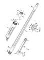
- FIG. 2is an exploded isometric view of the barrel, a barrel extension, a barrel nut, a bolt assembly, and receiver of the firearm of FIG. 1A .
- FIG. 3is isometric view of the barrel extension and a bolt head of the bolt assembly of FIG. 2 .
- FIG. 4is a cross-sectional view of the barrel mounting and retention device of FIGS. 1A-1B .
- FIGS. 5A-5Bare isometric views of the firearm of FIG. 1A illustrating the detachment and barrel removal according to the principles of the present invention.
- FIG. 6is an isometric view of the firearm of FIG. 1A with the barrel removed and a tool according to the principles of the present invention.
- FIG. 7is an isometric view of a firearm with a quick-detach barrel mounting system according to a second exemplary embodiment of the disclosure.
- FIG. 8is an exploded isometric view of features of the firearm of FIG. 7 .
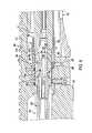
- FIG. 9is a cross-sectional view of the quick-detach barrel mounting system of FIG. 7 .
- FIG. 10is an isometric view of the quick-detach barrel mounting system of FIG. 7 with a tool according to the principles of the present invention.
- the figuresillustrate example embodiments of the quick-detach barrel mounting and retention apparatus or system according to the principles of the present disclosure for use in a firearm such as a precision sniper rifle (PSR), modular sniper rifle (MSR), and/or similar types of firearms.
- a firearmsuch as a precision sniper rifle (PSR), modular sniper rifle (MSR), and/or similar types of firearms.
- PSRprecision sniper rifle
- MSRmodular sniper rifle
- the principles of the barrel mounting and retention device of the present inventioncan be used in various types of firearms including shotguns, rifles, and other long guns.
- the illustrated embodimentincluded by way of example, shows a bolt action firearm.
- the present disclosureshould not be limited to the illustrated example.
- FIG. 1Aillustrates a firearm 10 showing a quick-detach barrel mounting system 11 in one exemplary embodiment.
- the firearm 10generally is shown as a rifle and includes a barrel 12 extending along a longitudinal axis L and having a forward or muzzle end 12 a and a proximal or rear end 12 b , with the a quick-detach barrel mounting system 11 connecting the barrel to an receiver 14 .
- the firearmfurther generally includes a chassis 15 , and a stock 18 .
- a hand guard 20also can be affixed to at least the receiver 14 , extending along the barrel with the barrel “floating” therein.
- the firearmcan include a hand guard that is affixed to the receiver 14 and/or the chassis 15 by fasteners, for example, or an AR-style two-piece receiver and hand guard.
- the hand guard 20 or any other type of hand guardcan be integral with and/or otherwise utilized with the firearm 10 , or a hand guard can be omitted from the firearm.
- the firearmadditionally can incorporate a monolithic, integral upper-style receiver and hand guard, wherein the hand guard is integrally formed with the receiver.
- the hand guard 20generally will include a cutout 21 to provide access to a barrel mounting and retention device 40 , the cutout 21 and the barrel mounting and retention device 40 forming the quick-detach barrel mounting system 11 .
- the stock 18also known as the buttstock or shoulder stock, may be formed in any conventional manner to include cushioning, special curvatures, grips, hinges, adjustment features, etc.
- the receiver 14houses and includes the firing mechanism or fire control 16 of the firearm, including a trigger 17 for actuating the firearm ( FIG. 1A ).
- a breech bolt or bolt assembly 22 and a firing pin 24also generally will be included in the receiver 14 ( FIGS. 2 and 4 ).
- the bolt assembly 22is translatable axially in both forward and rearward directions along the receiver during the ejection and loading cycle and generally is located behind and communicates with a barrel extension 26 and a chamber portion 19 ( FIG. 4 ) at the rear end 12 b of the barrel 12 .
- the chamberreceives a round of ammunition R ( FIG. 1A ), such as a shell or cartridge for firing, typically from a magazine M ( FIG. 1A ) received within the chassis 15 .
- the receiver 14 and the chassis 15can be secured together (e.g., with fasteners).
- the receiver 14includes a front end 73 that defines an axial bore 72 .
- the axial bore 72can receive a portion of the barrel extension 26 , which is part of the barrel mounting and retention device 40 ( FIG. 4 ).
- the front end 73includes an externally-threaded portion 73 a that interfaces with a barrel nut 42 of the barrel mounting and retention device 40 ( FIG. 4 ).
- the front end 73can include a notch or recess 77 in the forward facing surface 75 of the receiver 14 that can receive an alignment feature in the barrel extension 26 ( FIG. 4 ).
- the hand guard 20generally will enclose at least a portion of the barrel 12 with the barrel affixed to the receiver 14 by the barrel mounting and retention device 40 and generally floating or otherwise remaining free from connection to the hand guard 20 .
- the hand guard 20can include one or more Picatinny rails 23 and/or other accessory features, and one or more accessories (e.g., a scope, a flashlight, etc.) can be affixed to one or more of the Picatinny rails 23 .
- a proximal end 25 of the hand guard 20further can be in abutting contact with or otherwise engage a forward face of the chassis 15 ( FIG.
- the hand guard 20also can include an upper extension 29 that extends over and is secured to the receiver 14 ( FIG. 1C ), such as by fasteners 31 (e.g., cap screws, rivets, pins, etc.), shown in one embodiment as comprising four screws that pass through holes in the upper extension 29 and engage respective threaded bores in the top of the receiver 14 ( FIG. 1C ).
- fasteners 27e.g., cap screws, rivets, pins, etc.
- the upper extension 29can include a portion of a monolithic rail that is integrally formed with or can be affixed to the receiver and a guard portion of the hand guard 20 .
- the hand guard 20can be otherwise secured to or integral with the receiver 14 and/or the chassis 15 .
- the cutout 21 of the hand guard 20is formed between a rearward face of the hand guard 20 and the receiver 14 above the proximal end 25 of the hand guard ( FIGS. 1B and 1C ).
- the upper extension 29 of the hand guard 20can extend over the cutout 21 , with the cutout including/defining a series of spaced access openings or areas about the circumference of the hand guard.
- the cutout 21can be formed with the hand guard 20 (e.g., the cutout 21 can be formed by a feature of a mold when molding the hand guard).
- the cutout 21can be cut, carved, shaved, and/or otherwise formed in the pre-formed hand guard 20 .
- the cutout 21can include a first longitudinal edge 33 on a first side 114 of the firearm 10 , a second longitudinal edge 35 on the opposing second side 116 of the firearm, and a rearward-facing edge 36 extending between the first longitudinal edge 33 and the second longitudinal edge 35 . Accordingly, the cutout 21 generally will be configured to provide easy access to the barrel nut 42 on either side of the firearm 10 to enable engagement and manipulation of the barrel nut by hand, from either side of the firearm, while the hand guard 20 remains attached to the receiver 14 and the chassis 15 . In one embodiment, the cutout 21 is sized so that a tool (e.g., the tool 100 shown in FIG. 5A ) and/or a user's fingers can access and manipulate the barrel nut 42 through the cutout 21 without removing the hand guard 20 , and without diminishing the stability of the mounting of the barrel or the hand guard to the receiver.
- a toole.g., the tool 100 shown in FIG. 5A
- the longitudinal edges 33 , 35 of the cutoutare generally parallel to and disposed below the longitudinal axis L of the barrel 12 so that the top half and at least a portion of the lower half of the barrel nut 12 are accessible through the cutout, above the longitudinal edges 33 , 35 . Accordingly, a user can grasp the barrel nut through the cutout 21 below a ridge 110 on one side of the firearm and above a generally opposing ridge 110 on the other side of the firearm with respective fingers of one or both hands to rotate the barrel nut on the front end 73 of the receiver 14 .
- the rearward-facing edge 36 of the cutoutis spaced apart from the front end 73 of the receiver 14 ( FIG.
- the cutout 21 and the hand guard 20also can be otherwise configured without departing from the scope of the disclosure.
- the cutoutcould be formed on a single side of the firearm, or could additionally provide access to the barrel nut 42 from the top and/or the bottom of the firearm.
- the cutoutgenerally will be located along the hand guard and will be configured and sized to accommodate easy and consistent access to the barrel nut by different users with various hand sizes, including when users wear gloves, without interfering with or otherwise diminishing the strength of the connection between the receiver and the hand guard, including integrally formed receivers and hand guards.
- the cutout 21can provide a total access opening size of approximately 1-4 square inches, although greater or lesser total opening sizes also can be used, on one or both sides of the firearm 10 to provide clearance for various hand sizes, with a range of finger sizes from small fingers to large, gloved fingers to reach through the cutout and engage the ridges 110 of the barrel nut and to move up and/or down in the cutout to turn the barrel nut.
- the bolt assembly 22is shown in one embodiment as including a bolt body 28 , a bolt head 30 , and a bolt plug 32 ( FIGS. 2 and 4 ) for operation of the firearm for ejecting a spent shell or casing and reloading the chamber after firing by way of translating the bolt assembly 22 of the firearm 10 rearwardly and forwardly in relation to the receiver 14 .
- the bolt assemblyis rotated and pulled rearwardly away from the chamber portion 19 of the barrel 12 .
- This rearward translation of the boltcauses a spent cartridge/shell casing to be automatically cleared or ejected from the chamber 19 (e.g., by an extractor and ejector mechanism in the bolt head 30 ).
- a new round Rthen can be advanced and positioned adjacent the bolt head 30 by the magazine M, and the bolt assembly 22 can be pushed forward and locked into engagement with the barrel extension 26 so that the round R is loaded into the chamber.
- the boltcan be recocked and readied for firing.
- the barrel mounting and retention device 40includes a barrel nut 42 and the barrel extension 26 , which cooperate to secure and retain the barrel 12 in abutting engagement with the receiver 14 .
- the barrel extension 26generally includes a cylinder section 46 and an annular boss or collar 48 .
- the cylinder section 46can include an axial bore 50 extending from a bolt-receiving end 52 of the barrel extension 26 to a barrel-receiving end 54 adjacent the collar 48 .
- the axial bore 50can include a bolt-interlocking section 56 adjacent the bolt-receiving end 52 and a threaded section 58 extending from the bolt interlocking section 56 to the barrel-receiving end 54 for engaging external threads 59 formed about the rear end 12 b or the chamber portion 19 of the barrel 12 ( FIGS. 2 and 4 ).
- the cylinder section 46can slide axially into the axial bore 72 of the receiver 14 ( FIGS. 2 and 4 ) to interface with the bolt assembly 22 of the firearm 10 .
- the bolt-receiving end 52further includes a plurality of locking lugs 60 extending radially into the axial bore 50 with recesses 62 formed between the locking lugs 60 .
- the bolt head 30 of the bolt assembly 22can include a plurality of corresponding lugs 61 and recesses 63 at its forward end.
- the lugs 61 of the bolt head 30can engage the recesses 62 of the barrel extension 26 and the locking lugs 60 of the barrel extension 26 can engage the recesses 63 of the bolt head 30 when the forward end of the bolt head 30 is passed through the bolt-receiving end 52 and into the interlocking section 56 of the barrel extension 26 , such as when chambering a round R into the chamber 19 . Thereafter, with the lugs 61 of the bolt head 30 received within the interlocking section 56 ( FIG. 4 ), the bolt assembly 22 can be rotated to at least partially align the lugs 61 of the bolt head 30 with the locking lugs 60 to lock the bolt assembly 22 to the barrel extension 26 ( FIG. 4 ) for firing the firearm 10 .
- the bolt assembly 22can be rotated in an opposite direction so that the lugs 61 of the bolt head 30 are generally aligned with the recesses 62 of the barrel extension 26 and the bolt head 30 then can be pulled rearwardly to withdraw from the barrel extension 26 ( FIG. 3 ) to extract a spent shell or cartridge casing from the chamber prior to chambering another round.
- the bolt assembly 22can include a bolt handle 34 extending from the bolt body 28 .
- the bolt handle 34can be grasped for rotating and translating the bolt assembly 22 within the receiver 14 .
- the bolt assembly 22 and the ejection and loading cyclecan be controlled by a gas operating system in an automatic or semi-automatic firearm.
- the threaded section 58 of the axial bore 50can receive the rear end 12 b of the barrel 12 , which includes at least a portion of the chamber 19 .
- the threaded section 58can be threaded for interfacing with the external threads 59 formed about the rear end 12 b of the barrel 12 for attaching the barrel to the barrel extension.
- the collar 48can engage and abut against a shoulder 66 proximate the external threads 59 of the barrel 12 when the barrel extension 26 is in engagement with the rear end 12 b of the barrel.
- an annular barrel stop shouldercan be formed within the axial bore at the barrel-receiving end 54 , and the barrel stop shoulder can engage the rearward face of the shoulder 66 .
- the collar 48 of the barrel extension 26generally includes a rearward face 68 and a forward face 70 .
- the rearward face 68extends outwardly from the cylinder section 46 in a generally radial direction to provide a generally flat rearward facing surface for engaging the forward facing surface 75 of the receiver 14 ( FIGS. 2 and 4 ). Accordingly, a clamp force applied along the longitudinal axis L of the barrel 12 tends to urge the rearward face 68 against the forward surface 75 of the receiver.
- the generally flat nature of the rearward face 68allows proper seating of the collar 48 against the receiver 14 for secure retention of the barrel extension 26 , and thus the barrel 12 , to the receiver 14 , as well as proper alignment of the longitudinal axis L of the barrel 12 with a longitudinal axis of the receiver, with minimal effort by a user. No tools are required for alignment of the barrel and the receiver.
- the barrel extension 26can be inserted into the axial bore 72 of the front end 73 of the receiver 14 until a rearward face 74 of the bolt-receiving end 52 of the barrel extension 26 engages a stop shoulder 76 of the axial bore 72 of the receiver.
- the axial bore 72 and the cylinder section 46can be configured so that both of the rearward faces 68 , 74 of the barrel extension 26 engage the respective forward surface 75 and stop shoulder 76 of the receiver 14 , or only one of the rearward faces 68 , 74 engages the respective forward surface 75 or stop shoulder 76 .
- rearward faces 68 , 74 , the forward surface 75 , and the stop shoulder 76are generally perpendicular to the longitudinal axis L of the firearm as shown in the figures, one or more of these features can be oblique and/or curved to encourage alignment and/or proper seating of the respective features.
- the barrel extension 26can include an alignment pin 78 extending radially from the cylinder section 46 that engages the recess 77 in the forward surface 75 of the receiver 14 ( FIGS. 2 and 4 ).
- the alignment pin 78is seated in a bore in the cylinder section 46 of the barrel extension 26 and is secured by adhesive or an interference fit with the bore, for example.
- the alignment pin 78can be integral with the cylinder section 46 and/or the collar 48 .
- the alignment pin 78 and the recess 77can be configured so that when the alignment pin 78 engages the recess 77 ( FIG.
- the bolt interlocking section 56 of the barrel extension 26is properly aligned within the receiver to receive the forward portion of the bolt head 30 and to interlock with the bolt head 30 .
- the barrel extension 26could be otherwise configured or omitted without departing from the disclosure.
- the collar 48 , the locking lugs 60 and recesses 62 , and/or the alignment pin 78could be formed with (e.g., integral with) and/or directly attached to the rear end 12 b of the barrel 12 .
- the barrel nut 42can include a body 80 defining an axial bore 82 and a plurality of radial bores 84 .
- the axial bore 82can provide clearance for the rear end 12 b and the shoulder 66 of the barrel 12 to pass through and engage the barrel extension 26 . Accordingly, the barrel nut 42 can slide over and along the barrel 12 to engage the collar 48 of the barrel extension 26 and the front end 73 of the receiver 14 , as shown in FIGS. 1A and 4 .
- the barrel nut 42includes a forward end 86 , a rearward end 88 , an intermediate annular shoulder 90 , and a threaded portion 92 extending from the rearward end 88 to proximate the intermediate annular shoulder 90 .
- the radial bores 84are disposed between the forward end 86 and the intermediate annular shoulder 90 and generally are spaced substantially equally around a circumference of the body 80 of the barrel nut 42 .
- the number of radial bores 84can be varied with there being a sufficient number and spacing between the bores to enable engagement thereof from either side and from various angles as needed for disengagement of the barrel nut.
- the radial borecan be any suitable mating geometry (e.g., various bore shapes, slits, cutouts, protuberances, detents, grooves, etc.) without departing from the disclosure.
- the threaded portion 92is configured to provide clearance for the collar 48 and is internally threaded to engage the externally-threaded portion 73 a of the front end 73 of the receiver 14 ( FIGS. 2 and 4 ). Accordingly, the barrel nut 42 can be tightened onto the front end 73 over the barrel 12 and the barrel extension 26 until the intermediate annular shoulder 90 engages the forward face 70 of the collar 48 , thereby securing the barrel 12 and the barrel extension 26 in the front end 73 of the receiver 14 . In one embodiment, the barrel nut 42 and the front end 73 can apply a clamp force to the collar 48 between the forward facing surface 75 of the receiver 14 and the intermediate annular shoulder 90 of the barrel nut 42 .
- the radial bores 84 of the barrel nut 42can be configured to receive an end of a tool 100 , which can include a variety of wrenches, pry-bars, or other similar tools, including knives and other common tools used by soldiers and hunters in the field that can be used to engage at least one radial bore 84 for tightening and at least initially loosening the barrel nut 42 from its engagement with the front end 73 of the receiver 14 .
- the tool 100can include an elongate handle 102 , one or more tool projections 104 , and a tool guard 106 .
- the tool projection 104can be received in any of the radial bores 84 of the barrel nut 42 that is accessible through the cutout 21 in the hand guard 20 ( FIGS. 1A-1C ).
- the tool guard 106can have a curved surface for engaging the curved outer surface of the barrel nut 42 .
- the tool 100is shown by way of example only.
- any suitable toolcan be used to interface with the radial bores 84 (or other mating geometries) of the barrel nut 42 to provide a mechanical advantage for tightening and loosening the barrel nut 42 of the front end 73 of the receiver 14 .
- the toolcan be a torque wrench, and/or it can include multiple prongs, projections, recesses, etc.
- the toolalso can be compact for easier carrying and storing, for example, including a shortened or a telescoping and/or folding handle/tool body for compact storage and providing more mechanical advantage in use.
- the barrel nut 42further can include ridges 110 to provide a gripping surface that can be used for tightening and loosening the barrel nut 42 on the front end 73 of the receiver 14 . Accordingly, the barrel nut 42 can be initially tightened onto the front end 73 by a user's fingers, which can grip the ridges 110 and rotate the barrel nut 42 in the clockwise direction. The barrel nut 42 can be securely tightened onto the front end 73 by inserting the tool projection 104 into an radial bore 84 at the cutout 21 and pushing or pulling the handle 102 of the tool 100 to rotate the barrel nut 42 in the clockwise direction.
- the barrel nut 42can be initially loosened by inserting the tool projection 104 into an radial bore 84 at the cutout 21 and pushing or pulling the handle 102 to rotate the barrel nut 42 in the counterclockwise direction. A user then can loosen the barrel nut 42 further by gripping the barrel nut 42 at the ridges 110 and rotating the barrel nut 42 in the counterclockwise direction.
- the tool 100can access the barrel nut 42 through the cutout 21 on the first side 114 of the firearm 10 so that pushing up on the tool 100 rotates the barrel nut 42 in a clockwise motion to tighten the barrel nut 42 onto the front end 73 of the receiver 14 .
- Pulling down on the tool 100 on the first side 114 of the firearm 10rotates the barrel nut 42 in a counterclockwise motion to loosen the barrel nut 42 .
- the tool 100can access the barrel nut 42 through the cutout 21 on the opposing second side 116 of the firearm 10 so that pulling down on the tool 100 rotates the barrel nut 42 in a clockwise motion to tighten the barrel nut 42 onto the front end 73 and pushing up on the tool 100 rotates the barrel nut 42 in a counterclockwise motion to loosen the barrel nut 42 .
- the threaded portion 92 of the barrel nut 42 and the externally-threaded portion 73 a of the front end 73could be threaded so that turning the barrel nut 42 in a counterclockwise motion tightens the barrel nut 42 onto the front end 73 and rotating the barrel nut 42 in a clockwise motion loosens the barrel nut 42 .
- the barrel 12 of the firearm 10can be exchanged with an another barrel 12 without disassembling the hand guard assembly 20 and/or other features of the firearm.
- the barrelmay be replaced by a barrel with a different length and/or that is configured for use with a different caliber of ammunition.
- the original barrel extension 26 and barrel nut 42can be used with the alternate barrel, or one or both of the barrel extension 26 and barrel nut 42 can be replaced with the barrel.
- the barrel change-out operationcan be initiated by disengaging the bolt assembly 22 from the barrel extension 26 and retracted within the receiver 14 .
- the bolt handle 34can be manipulated to rotated the bolt assembly 22 and align the lugs 61 of the bolt head 30 with the recesses 62 of the barrel extension 26 .
- the bolt assembly 22can then be at least partially retracted in the receiver 14 so that the lugs 61 pass through the recesses 62 and the bolt head 30 is removed from the bolt-receiving end 52 of the barrel extension 26 .
- the bolt assembly 22can be fully removed from the receiver 14 so that the firing pin 24 , the bolt head 30 , and/or other features of the bolt assembly 22 can be replaced.
- the tool projection 104 of the tool 100can be inserted into one of the radial bores 84 that is accessible through the cutout 21 of the hand guard assembly 21 .
- the tool 100is inserted through the cutout 21 from the first side 114 of the firearm 10 ; however, the tool 100 could be inserted through the cutout 21 from the second side 116 of the firearm.
- the tool guard 106 of the tool 100can contact the outer surface of the barrel nut 42 adjacent the radial bore 84 . Pulling downwardly on the handle 102 of the tool 100 can help loosen the barrel nut 42 on the front end 73 of the receiver 14 .
- Friction due to contact between the intermediate annular shoulder 90 of the axial bore 82 of the barrel nut 42 and the forward face 70 of the collar 48 of the barrel extension 26can resist rotation of the barrel nut 24 relative to the barrel extension 26 and the front end 73 . Additionally, residue can build up between the annular should 90 of the barrel nut 42 and the collar 48 of the barrel extension 26 and/or between the threaded portions 73 a , 92 from the primer and the propellant of the rounds R after several firing operations to form an adhesive bond between the barrel nut 42 and the front end 73 . Also, stress from firing operations can further tighten the barrel nut 42 on the front end 73 , which can make it more difficult to initiate turning of the barrel nut 42 .
- the tool 100can form a lever to provide a mechanical advantage to overcome the friction and any adhesion between the annular shoulder 90 and the collar 48 and/or the threaded portions 73 a , 92 and to rotate the barrel nut 42 in a counterclockwise motion.
- the interfacing of the threaded portion 92 of the barrel nut 42 and the externally-threaded portion 73 a of the front end 73moves the barrel nut 42 away from the receiver 14 and the barrel extension 26 along the longitudinal axis L as the barrel nut 42 rotates in the counterclockwise direction. Accordingly, the intermediate annular shoulder 90 of the barrel nut 42 is moved away from the forward face 70 of the collar 48 so that the barrel nut 42 can be more easily rotated in the counterclockwise direction.
- the tool 100can be withdrawn from the firearm 10 , and the barrel nut 42 can be further rotated in the counterclockwise direction with a user's fingers until the threaded portion 92 of the barrel nut 42 is disengaged from the externally-threaded portion 73 a of the front end 73 ( FIG. 5B ).
- the barrel 12can be pulled away from the receiver 14 , withdrawing the cylinder section 46 from the axial bore 72 of the receiver 14 .
- the barrel 12 , the barrel extension 26 , and the barrel nut 42can be pulled through a forward end 112 of the hand guard 20 to be fully removed from the firearm 10 while the hand guard 20 remains mounted on the receiver 14 and/or the chassis 15 .
- the barrel 12 , the barrel extension 26 , and the barrel nut 42can be removed from the firearm 10 by other steps and/or features without departing from the disclosure.
- the barrel 12 , the barrel extension 26 , and the barrel nut 42can be reassembled to the receiver 14 by generally reversing the removal steps.
- the rear end 12 b of the barrel 12can be engaged with the axial bore 50 of the barrel extension 26 by screwing the threaded portion 59 of the rear end 12 b into the threaded section 58 of the axial bore 50 until the forward face 70 of the barrel extension 26 engages the shoulder 66 of the barrel 12 .
- the rear end 12 bcan be further secured to the barrel extension 42 with adhesives, set screws, other fasteners, or combinations thereof, although such additional attachment devices are not required with the present disclosure.
- the barrel nut 42can slide over the barrel 12 from the muzzle end until the axial bore 82 of the barrel nut 42 is proximate the rear end 12 b of the barrel ( FIG. 6 ).
- the barrel extension 26 , the barrel 12 , and the barrel nut 42can be inserted through the forward end 112 of the hand guard 20 and the cylinder section 46 of the barrel extension 26 can be inserted into the axial bore 72 of the receiver 14 .
- the barrel 12 and the barrel extension 26can be rotated to align the alignment pin 78 of the barrel extension 26 with the recess 77 of the front end 73 of the receiver 14 , and the barrel extension 26 can be further inserted into the axial bore 72 until the alignment pin 78 is received in the recess 77 ( FIG.
- the barrel nut 42can be secured onto the front end 73 of the receiver 14 by engaging the threaded portion 90 of the barrel nut 42 with the externally-threaded portion 73 a of the front end 73 and rotating the barrel nut 42 in the clockwise direction.
- a usercan initially tighten the barrel nut 42 on the front end 73 with fingers by gripping the ridges 110 through the cutout 21 of the hand guard assembly 20 on one or both sides 114 , 116 of the firearm 10 and rotating the barrel nut 42 at least until the radial bores 84 are disposed within the cutout 21 .
- the tool projection 104 of the tool 100can be inserted into one of the radial bores 84 (e.g., from the first side 114 of the firearm 10 as shown in FIG. 5A ).
- the handle 102 of the tool 100can be pushed upwardly in order to tighten barrel nut 42 onto front end 73 until the intermediate annular shoulder 90 of the barrel nut 42 engages forward face 70 of the collar 48 of the barrel extension 26 ( FIG. 4 ).
- the barrel nut 42can clamp the collar 48 between the forward facing surface 75 of the receiver 14 and the intermediate annular shoulder 90 of the barrel nut 42 to help secure the barrel 12 and the barrel extension 26 to the receiver 14 .
- the bolt assembly 22can be pushed forward within the receiver 14 so that the bolt head 30 engages the bolt-interlocking section 56 of the barrel extension 26 . Accordingly, the lugs 61 of the bolt head 30 can be aligned with the recesses 62 between the locking lugs 60 of the barrel extension 26 , bolt assembly 22 can be pushed forward so that the lugs 61 are generally clear of the locking lugs 60 within the axial bore 50 of the barrel extension 26 .
- the bolt assembly 22can be rotated by the bolt handle 34 so the lugs 61 are aligned with the locking lugs 60 and the bolt head 30 is locked with the barrel extension 26 ( FIG. 4 ).
- the barrel 12 , the barrel extension 26 , and the barrel nut 42can be secured to the firearm 10 by other steps and/or features without departing from the disclosure.
- the firearm 10can be prepared for firing by engaging the magazine M with rounds R with the chassis 15 , rotating the bolt assembly 22 by the bolt handle 34 to align the lugs 61 with the recesses 62 , and pulling the bolt assembly 22 rearwardly in the receiver 14 by the handle 34 so that a round R can enter the receiver 14 ahead of the forward-facing end of the bolt head 30 .
- the bolt assembly 22can be pushed forwardly in the receiver 14 by the handle 34 to push the round R forwardly toward the chamber 19 .
- the bolt assembly 22can be locked with the barrel extension 26 as described above, while the bolt head 30 pushes the round R into the chamber 19 .
- the firing operationcan be actuated by operating the fire control 16 (e.g., pulling the trigger 17 ). After the firing operation, the bolt assembly 22 can be withdrawn in the receiver 14 to eject the spent cartridge or shell casing of the round R and to receive a new round R for chambering and preparing for firing.
- the firearm 10( FIG. 1 ) is prepared for firing when the bolt assembly 22 loads a round of ammunition R in to the chamber portion 19 of the firearm.
- the bolt head 30carries the round R into the axial bore 50 at the bolt-receiving end 52 of the barrel extension 26 and the lugs 61 of the bolt head 30 pass through the recesses 62 between the locking lugs 60 at the bolt-receiving end 52 .
- the round Ris fully inserted into the chamber portion 19 of the barrel 12 , and the bolt assembly 22 is rotated to align the lugs 61 with the locking lugs 60 at the bolt-receiving end 52 and lock bolt assembly 22 to the barrel extension 42 with the round R in the chamber portion 19 .
- the firing pin 24strikes the primer of the round, igniting the propellant. Expanding gases from the ignited propellant build up pressure in the barrel 12 , driving the bullet portion of the round through the down bore section 12 a of the barrel.
- the bolt assembly 22then can be rotated to unlock the lugs 61 from the barrel extension 42 and to extract the spent casing of the round R from the chamber 19 .
- the spent casingcan be ejected from the firearm 10 and a new round can be loaded into the chamber.
- FIG. 7is a perspective view of a quick-detach barrel mounting system 211 for a firearm according to a second embodiment of the disclosure.
- the second embodimentgenerally is similar to the first embodiment, except for various additional noted features and variations that will be apparent to one of ordinary skill in the art. Accordingly, similar or identical features of the embodiments have been given like or similar reference numbers.
- the quick-detach barrel mounting system 211is associated with a firearm 210 , which can be similar to the firearm 10 of the first embodiment shown in FIG. 1 .
- the firearm 210can include a barrel 212 mounted to a receiver 214 , which is mounted to a chassis 215 .
- the hand guard assembly 220can be similar or identical to the hand guard assembly 20 of the first embodiment and can include the cutout 21 .
- the hand guard assembly 220can be mounted to the chassis 215 and the receiver 214 with the barrel 212 extending (e.g., “floating”) therein in a similar or identical manner that the hand guard assembly 20 is mounted to the chassis 15 and the receiver 14 .
- the barrel 212includes a forward or muzzle end 212 a and a proximal or rear end 212 b .
- the proximal end 212 bcan include external threads 259 for threadably engaging internal threads 273 a of an axial bore 272 in the receiver 214 .
- turning the barrel 212 in a clockwise directioncan move the barrel rearwardly into the axial bore 272 of the receiver, and turning the barrel in a counterclockwise direction can move the barrel forwardly, out of the receiver 214 .
- a bolt assembly 222can be at least partially disposed in the receiver 214 and can translate axially along the receiver during the ejection and loading cycle of the firearm.
- the bolt assembly 222is located behind and communicates with a chamber portion 219 at the proximal end 212 b of the barrel 212 in the axial bore 272 of the receiver 214 ( FIG. 9 ).
- the chamber 219receives a round of ammunition ( FIG. 7 ), such as a shell or cartridge for firing.
- a recoil lug or barrel bracket 294( FIGS. 8 and 9 ) can be disposed on the proximal end 212 b of the barrel 212 adjacent the forward facing surface 275 of the receiver 214 .
- the barrel bracket 294can include a barrel-receiving bore 295 and a flange 296 .
- the proximal end 212 b of the barrelcan extend through the barrel-receiving bore 295 , and the flange 296 can be received in a slot 297 in the chassis 215 ( FIGS. 8 and 9 ).
- An alignment pin 298can be received in a corresponding alignment bore 299 in the barrel bracket 294 and the forward facing surface 275 of the receiver in order to help align the barrel bracket 294 with the receiver 214 .
- the alignment pin 298can be secured (e.g., press fit, glued, etc.) within the bore in the barrel bracket 294 or the forward facing surface 275 of the receiver.
- the barrel bracket 294can be otherwise configured or omitted without departing from the scope of the disclosure.
- the quick-detach barrel mounting system 211includes a cutout 21 along the hand guard 220 and an barrel nut 242 that can be configured as a jam nut.
- the barrel nut 242can include a body 280 defining an axial bore 282 .
- the barrel nut 242includes a forward end 286 , a rearward end 288 , a forward facing, intermediate annular shoulder 290 , and a threaded portion 292 extending from the rearward end 288 to proximate the forward facing shoulder 290 .
- the axial bore 282can receive the rear end 212 b of the barrel, and the forward facing shoulder 290 can be configured to engage a shoulder 266 at the forward end of the proximal end 212 b of the barrel 212 to help prevent the barrel nut 242 from sliding forwardly along the barrel.
- the threaded portion 292can engage external threads 259 of the proximal end 212 b so that, for example, turning the barrel nut 242 in the clockwise direction (as viewed from the muzzle end 212 a ) can move the barrel nut rearwardly along the proximal portion 212 b , and turning the barrel nut in the counterclockwise direction will move the barrel nut forwardly until the forward facing shoulder 290 engages the shoulder 266 of the barrel 212 .
- the barrel nut 242can be otherwise configured or omitted without departing from the scope of the disclosure.
- the barrel nut 242further can include ridges 310 to provide a gripping surface that can be used for turning the barrel nut 242 on the proximal end 212 b of the barrel 212 .
- the ridges 310can define recesses or grooves 284 between adjacent ridges, and the grooves 284 can be configured for mating with a spanner wrench 300 ( FIG. 10 ).
- the grooves 284can be any suitable mating geometry (e.g., various bore shapes, slits, cutouts, protuberances, detents, etc.) without departing from the disclosure.
- the barrel nut 242can include radial bores 84 , cuts or recesses for mating with the tool 100 of the first embodiment.
- the spanner wrench 300can include a body 301 with a bracket portion 302 and a semicircular or arc-shaped engaging portion 303 .
- the bracket portion 302can include an opening 305 , which can be configured to receive a torque wrench (not shown) or other tool (e.g., a lever).
- the bracket portion 302can be formed as an elongate handle.
- arc-shaped portion 303includes spaced apart projections 304 that generally can be spaced so as to align with the grooves 284 of the barrel nut 242 .
- the indented portions between the projections 304also can provide clearance for the ridges 310 .
- the spanner wrench 300can be otherwise configured or omitted without departing from the scope of the disclosure.
- the spanner wrench 300could be replaced by any suitable tool for engaging one or more grooves 284 and/or ridges 310 .
- the arc-shaped engaging portion 303 of the spanner wrenchcan be formed as a closed circle, and can include an elongate, longitudinal rod (not shown). Such a closed circular engaging portion of the spanner wrench can be placed over the muzzle end 212 a of the barrel 212 , and the rod can be used to push the alternative spanner wrench rearwardly along the barrel, and along the interior of the hand guard 220 , until the bracket portion 302 is accessible via the cutout 21 of the hand guard.
- the barrel nut 242can be initially tightened against the barrel bracket 294 by a user's fingers, which can grip the ridges 310 and rotate the barrel nut 242 in the clockwise direction.
- the barrel nut 242further can be securely tightened against the barrel bracket 294 by sliding the spanner wrench 300 over the barrel nut 242 with the projections 304 sliding along the grooves 284 and then pushing or pulling the spanner wrench 300 to further rotate the barrel nut 242 in the clockwise direction.
- the barrel nut 242When the barrel nut 242 is sufficiently tightened on the proximal end 212 b of the barrel 212 , the barrel nut clamps the barrel bracket 294 against the forward facing surface 275 of the receiver 214 , and the threaded portion 292 of the barrel nut pulls the external threads 259 , and thus the proximal portion 212 b , forwardly.
- the pulling of the proximal portion 212 bis resisted by the interaction of the internal threads 273 a of the axial bore 272 of the receiver and the external threads 259 of the proximal end.
- the barrel nut 242increases the friction between the external threads 259 of the barrel and the internal threads 273 a of the receiver, which frictional engagement can help resist turning forces, recoil forces, vibrations, and other forces that can lead to loosening of the proximal end 212 b in the axial bore 272 of the receiver.
- the barrel nut 242thereafter can be initially loosened by sliding the spanner wrench 300 over the barrel nut to engage the projections 304 with the grooves 284 and then pushing or pulling the spanner wrench to rotate the barrel nut 242 in the counterclockwise direction. A user then can loosen the barrel nut 242 further by removing the spanner wrench 300 , gripping the barrel nut 242 at the ridges 310 , and rotating the barrel nut 242 in the counterclockwise direction.
- the barrel 212 of the firearm 210can be exchanged (e.g., for a barrel configured for a different caliber of ammunition, for a barrel with a different length, and/or to replace a worn-out barrel) with the quick-detach barrel mounting system 211 .
- the spanner wrench 300can be inserted into the cutout 21 of the hand guard 220 on either side of the firearm 210 so that the arc-shaped portion 303 is disposed over the rearward end 288 of the barrel nut 242 , to the rear of the ridges 310 .
- the arc-shaped engaging portion 303could be positioned over the barrel 212 adjacent the forward end 286 of the barrel nut 242 .
- the projections 304 of the spanner wrench 300are generally aligned with respective grooves 284 of the barrel nut 242 , and the spanner wrench is moved along the barrel nut 242 so that the projections 304 slide within the grooves 284 .
- a toolsuch as a torque wrench (e.g., the tool 100 of the first embodiment), a lever, etc., also can be engaged with the opening 305 of the spanner wrench 300 , and the tool can be used to push or pull the spanner wrench in the counterclockwise direction (as viewed from the muzzle end 212 a of the barrel 212 ).
- a torque wrenche.g., the tool 100 of the first embodiment
- a leveretc.
- the projections 304 of the spanner wrenchwill push against the sides of the respective grooves 284 of the barrel nut to urge the barrel nut 242 in the counterclockwise direction to help overcome the forces helping to retain the barrel nut 242 in position (e.g., the friction between the rearward end 288 of the barrel nut and the barrel bracket 294 , stresses causing friction between the threaded portion 292 of the barrel nut and the external threads 259 of the proximal end 212 b of the barrel, residue build-up between the barrel nut and the proximal end of the barrel, etc.).
- the barrel nut 242rotates in the counterclockwise direction, the barrel nut will be moved forward along the proximal end 212 b of the barrel 212 and away from the receiver 214 and the barrel bracket 294 .
- the spanner wrench 300can be removed by sliding the spanner wrench forwardly or rearwardly along the barrel nut until the projections 304 are disengaged from the grooves 284 .
- the spanner wrenchthen can be removed through the cutout 21 , and a user can reach through the cutout 21 and grasp the barrel nut 242 at the ridges 310 to continue turning the barrel nut in the counterclockwise direction so that the barrel nut moves forwardly on the proximal end 212 b .
- the barrel nut 242can be rotated until the forward facing shoulder 290 of the barrel nut engages the shoulder 266 of the barrel.
- the barrel nut 242With the barrel nut 242 moved away from the receiver 214 , the tension between the external threads 259 of the proximal end 212 b of the barrel 212 and the internal threads 273 a of the axial bore 272 of the receiver 214 will be reduced, and the barrel 212 can be rotated in the counterclockwise direction to unscrew the proximal end 212 b from the axial bore 272 . Accordingly, the barrel 212 can be withdrawn from the rest of the firearm 210 through the barrel-receiving bore 295 of the barrel bracket 294 and the interior of the hand guard 220 . The barrel nut 242 further can be rotated in the clockwise direction to unscrew the barrel nut from the proximal end 212 b of the barrel. The barrel 212 can be removed by other steps and/or features without departing from the present disclosure.
- the barrel nut 242can be engaged with the proximal end 212 b of the new/different barrel 212 by inserting the proximal end into the forward end 286 of the barrel nut and engaging the threaded portion 292 with the external threads 259 of the proximal end of the barrel. The barrel nut 242 then can be screwed onto the proximal end of the barrel until the forward facing shoulder 290 engages the shoulder 266 of the barrel 212 .
- a gauge 318can be inserted into the chamber 219 of the barrel for helping to position the proximal end 212 b in the axial bore 272 of the receiver 214 with the proper spacing from the bolt assembly 222 in the locked, ready to fire position for ensuring proper safe case support and rifle function.
- the gauge 318can be otherwise configured or omitted without departing from the description.
- the proximal end 212 b of the barrel and the barrel nut 242can be inserted through the forward end of the hand guard 220 , and the proximal end can be inserted through the barrel-receiving bore 295 of the barrel bracket 294 to engage the axial bore 272 of the receiver.
- the external threads 259 of the proximal endcan be engaged with the internal threads 273 a of the axial bore 272 , and the proximal end 212 b can be screwed into the axial bore 272 by rotating the barrel 212 in the clockwise direction. As shown in FIG.
- the gauge 318will engage the bolt head and prevent further movement of the proximal end 212 b into the axial bore 272 . Accordingly, the installation of a gauge 318 can help to position the barrel in the receiver.
- a usercan reach into the cutout 21 of the hand guard 220 , grasp the barrel nut 242 at the ridges 310 , and rotate the barrel nut 242 in the clockwise direction to move the barrel nut rearwardly along the external threads 259 of the proximal portion 212 b .
- the usercan initially tighten the barrel nut 242 against the barrel bracket 294 with fingers, for example.
- the spanner wrench 300can be inserted into the cutout 21 so that the arc-shaped portion is forward or rearward of the ridges 310 .
- the projections 304can be aligned with the grooves 284 and the spanner wrench 300 can slide over the barrel nut 242 with the projections 304 engaged with the grooves 284 .
- a toole.g., torque wrench
- a toolthen can be engaged with the opening 305 of the spanner wrench 300 to tighten the barrel nut 242 on the proximal end 212 b of the barrel against the receiver 214 , clamping the barrel bracket 294 between the rearward end 288 of the barrel nut and the forward facing surface 275 of the receiver and tensioning the external threads 259 of the proximal end 212 b against the internal threads 273 a of the axial bore 272 .
- the construction of the firearm with a barrel mounting and retention deviceprovides a firearm with an apparatus for affixing and retaining the barrel in a locked engagement with the receiver while further providing for substantially quick and easy attachment and removal of the barrel with the receiver without requiring extensive disassembly of the firearm.
- the barrel mounting and retention devicefacilitates a user's easy-attachment and removal/replacement of the barrel to the receiver of a firearm, including firearms with integral or monolithic receivers having hand guards integrally attached or formed therewith.
- the present barrel mounting and retention systemfurther enables replacement of the barrel without having to remove and/or replace the hand guard or other portions of the firearm.
- opticse.g., a day or night scope
- a Picatinny rail systemwould not need to be disassembled when changing the barrel, and may only require adjustment to a predetermined calibration (e.g., the user can have a known calibration for the optics for the particular sighting characteristics of each of the user's different barrels). Accordingly, a user can avoid extensive calibration of optics and/or other accessories requiring additional expertise and time when changing the barrel of a firearm.
Landscapes
- Engineering & Computer Science (AREA)
- General Engineering & Computer Science (AREA)
- Toys (AREA)
- Mutual Connection Of Rods And Tubes (AREA)
- Surgical Instruments (AREA)
Abstract
Description
Claims (17)
Priority Applications (1)
| Application Number | Priority Date | Filing Date | Title |
|---|---|---|---|
| US14/330,443US9234717B2 (en) | 2012-10-26 | 2014-07-14 | Quick detach barrel mounting system |
Applications Claiming Priority (2)
| Application Number | Priority Date | Filing Date | Title |
|---|---|---|---|
| US13/662,236US8782943B2 (en) | 2012-10-26 | 2012-10-26 | Quick detach barrel mounting system |
| US14/330,443US9234717B2 (en) | 2012-10-26 | 2014-07-14 | Quick detach barrel mounting system |
Related Parent Applications (1)
| Application Number | Title | Priority Date | Filing Date |
|---|---|---|---|
| US13/662,236ContinuationUS8782943B2 (en) | 2012-10-26 | 2012-10-26 | Quick detach barrel mounting system |
Publications (2)
| Publication Number | Publication Date |
|---|---|
| US20150247695A1 US20150247695A1 (en) | 2015-09-03 |
| US9234717B2true US9234717B2 (en) | 2016-01-12 |
Family
ID=49553862
Family Applications (2)
| Application Number | Title | Priority Date | Filing Date |
|---|---|---|---|
| US13/662,236ActiveUS8782943B2 (en) | 2012-10-26 | 2012-10-26 | Quick detach barrel mounting system |
| US14/330,443ActiveUS9234717B2 (en) | 2012-10-26 | 2014-07-14 | Quick detach barrel mounting system |
Family Applications Before (1)
| Application Number | Title | Priority Date | Filing Date |
|---|---|---|---|
| US13/662,236ActiveUS8782943B2 (en) | 2012-10-26 | 2012-10-26 | Quick detach barrel mounting system |
Country Status (4)
| Country | Link |
|---|---|
| US (2) | US8782943B2 (en) |
| EP (1) | EP2912400A1 (en) |
| CA (1) | CA2889273A1 (en) |
| WO (1) | WO2014066759A1 (en) |
Cited By (17)
| Publication number | Priority date | Publication date | Assignee | Title |
|---|---|---|---|---|
| US20150266168A1 (en)* | 2014-01-10 | 2015-09-24 | WHG Properties, LLC | Barrel installation tool |
| US9429387B1 (en) | 2015-03-20 | 2016-08-30 | Magpul Industries Corp. | Modular stock for a firearm |
| US9702652B1 (en) | 2016-03-16 | 2017-07-11 | Artisan Defense LLC | Rifle barrel nut and methods for coupling firearm components |
| US9851167B2 (en) | 2016-03-15 | 2017-12-26 | Clayton Dean Smith | Switch barrel recoil lug |
| US9851175B2 (en)* | 2015-04-27 | 2017-12-26 | Hunting Tactical, LLC | Fully adjustable gunstock with integrated tool holder |
| US9879935B2 (en) | 2016-03-29 | 2018-01-30 | Leo Takedown, Llc | Quick take-down firearm |
| US10101102B2 (en) | 2015-07-31 | 2018-10-16 | Magpul Industries Corp. | Magazine well for a firearm |
| USD844735S1 (en) | 2017-03-07 | 2019-04-02 | Magpul Industries Corp. | Firearm stock |
| US10345076B2 (en) | 2017-03-07 | 2019-07-09 | Magpul Industries Corp. | Firearm barrel tray, stock, and related methods |
| US10352643B2 (en) | 2016-09-21 | 2019-07-16 | Vincent P. Battaglia | Quad lock multicaliber rifle receiver with locking barrel |
| US10401122B2 (en) | 2017-06-08 | 2019-09-03 | Springfield, Inc. | Free floating handguard anchoring system |
| RU2714059C1 (en)* | 2019-06-28 | 2020-02-11 | Александр Леонидович Малиновский | Small arms |
| US10830551B2 (en) | 2016-03-29 | 2020-11-10 | Leo Takedown, Llc | Quick take-down firearm |
| USD923129S1 (en) | 2017-06-08 | 2021-06-22 | Springfield, Inc. | Free floating handguard anchoring system |
| US11187485B2 (en) | 2019-01-08 | 2021-11-30 | Cyrus Albright | Modular firearm muzzle attachment system |
| US11644279B2 (en) | 2019-12-04 | 2023-05-09 | Epic Mfg Llc | Systems and methods for simulated rifle rounds |
| US12018907B1 (en)* | 2019-06-26 | 2024-06-25 | Firearm Consulting Group, LLC | Barrel nut |
Families Citing this family (61)
| Publication number | Priority date | Publication date | Assignee | Title |
|---|---|---|---|---|
| US10184752B2 (en)* | 2015-07-30 | 2019-01-22 | G. David Tubb | Firearm accessory mounting interface, mirage shield and ergonomic method for configuring rifle components and accessories |
| US9719746B1 (en)* | 2012-09-11 | 2017-08-01 | General Dynamics—OTS, Inc. | Machine gun assembly and interlock element for use with a machine gun assembly |
| US8782943B2 (en)* | 2012-10-26 | 2014-07-22 | Ra Brands, L.L.C. | Quick detach barrel mounting system |
| US9423194B2 (en)* | 2013-05-31 | 2016-08-23 | Craig A. Fritz | Redesigned AR-15 upper receiver |
| US9003684B2 (en)* | 2013-08-27 | 2015-04-14 | Tim Shawn Bero | Compact survival firearm |
| US9429375B2 (en) | 2013-10-29 | 2016-08-30 | Patriot Ordnance Factory, Inc. | Systems and methods for improved firearm function |
| US9383154B2 (en) | 2013-12-12 | 2016-07-05 | Ra Brands, L.L.C. | Gas vent for firearm |
| US9562730B2 (en) | 2014-01-13 | 2017-02-07 | Ra Brands, L.L.C. | Replaceable feed ramp |
| US9429379B2 (en)* | 2014-02-10 | 2016-08-30 | California Business Environments, Inc. | Rimfire rifle |
| US9303949B1 (en)* | 2014-05-09 | 2016-04-05 | Paul Oglesby | Handguard attachment system having registration/retention tab |
| US9528793B1 (en)* | 2014-05-09 | 2016-12-27 | Paul Oglesby | Anti-rotation handguard system |
| US9658020B2 (en) | 2014-06-24 | 2017-05-23 | Daniel Defense, Inc. | Systems and methods for mounting barrels to firearms |
| EP3183530B1 (en)* | 2014-08-19 | 2019-10-02 | Beretta USA Corp. | Adjustable free-float forend/handguard mounting assembly |
| US9506712B2 (en)* | 2014-10-28 | 2016-11-29 | Sturm, Ruger & Company, Inc. | Firearm with tubular handguard mounting system |
| US10012462B2 (en) | 2015-01-20 | 2018-07-03 | Patriot Ordnance Factory, Inc. | Bolt carrier support system |
| US9322611B1 (en) | 2015-03-20 | 2016-04-26 | Magpul Industries Corp. | Modular stock for a firearm |
| US9513074B1 (en)* | 2015-06-01 | 2016-12-06 | Everett McDowell Steil | Firearm with interchangeable parts |
| US9464866B1 (en)* | 2015-10-16 | 2016-10-11 | Vega Force International Corp. | Toy gun assembly structure |
| US10578379B2 (en) | 2015-11-04 | 2020-03-03 | Patriot Ordinance Factory, Inc. | Firearm bolt carrier assembly kit |
| US10107582B2 (en) | 2015-12-04 | 2018-10-23 | Scott Gray | Quick connect rifle receiver adapter system |
| TWM522335U (en)* | 2015-12-29 | 2016-05-21 | Kriss Ind Asia Ltd | Firearm structure with exchangeable barrels of different specifications |
| USD804602S1 (en)* | 2016-01-12 | 2017-12-05 | Magpul Industries Corp. | Firearm stock |
| US10066897B2 (en)* | 2016-01-13 | 2018-09-04 | Fortis Manufacturing, Inc. | Expansion barrel nut systems and methods for attaching a handguard to an upper receiver of a firearm |
| US10132587B2 (en)* | 2016-01-19 | 2018-11-20 | Patriot Ordnance Factory, Inc. | Reduced weight firearm |
| US11846479B2 (en) | 2016-02-18 | 2023-12-19 | Ronald Andrew Foster | Firearms and components thereof featuring enhanced bolt lug shapes |
| US10466005B2 (en)* | 2016-02-18 | 2019-11-05 | Ronald Andrew Foster | Firearms and components thereof, for enhanced axial alignment of barrel with action |
| US10132579B2 (en) | 2016-02-18 | 2018-11-20 | Ronald Andrew Foster | Firearm with locking lug bolt, and components thereof, for accurate field shooting |
| EP3436764B1 (en)* | 2016-03-30 | 2019-10-09 | Turlakov, Maxim | Firearm with removable barrel |
| US9791239B1 (en)* | 2016-05-12 | 2017-10-17 | Bravo Company Mfg. Inc. | Firearm handguard assembly |
| US10295304B1 (en)* | 2016-05-12 | 2019-05-21 | Bravo Company Mfg, Inc. | Firearm handguard assembly |
| US10900743B2 (en) | 2016-05-12 | 2021-01-26 | Bravo Company Mfg, Inc. | Firearm handguard assembly |
| USD844091S1 (en) | 2016-10-20 | 2019-03-26 | Bravo Company Mfg, Inc. | Firearm handguard |
| US10260841B2 (en) | 2016-10-20 | 2019-04-16 | Bravo Company Mfg, Inc. | Firearm accessory mounting system |
| US10260838B1 (en) | 2016-10-20 | 2019-04-16 | Bravo Company Mfg, Inc. | Firearm handguard |
| WO2018087598A1 (en)* | 2016-11-14 | 2018-05-17 | Cadequip, Inc. | Interchangeable barrel assembly for a firearm and method of changing the barrel |
| USD827753S1 (en)* | 2016-12-20 | 2018-09-04 | Q, Llc | Firearm |
| US11131518B2 (en)* | 2017-01-13 | 2021-09-28 | Wilcox Industries Corp. | Modular barrel system and method for its manufacture |
| USD827760S1 (en) | 2017-06-16 | 2018-09-04 | Spec Arms LLC | Firearm upper |
| USD820937S1 (en) | 2017-06-16 | 2018-06-19 | Spec Arms LLC | Firearm lower |
| USD828480S1 (en)* | 2017-06-16 | 2018-09-11 | Spec Arms LLC | Firearm handguard |
| US10619971B2 (en)* | 2017-09-22 | 2020-04-14 | Sig Sauer, Inc. | Handguard attachment system for a firearm |
| US10551145B2 (en) | 2017-10-18 | 2020-02-04 | Bravo Company Mfg, Inc. | Modular key-slot accessory mounting system for a firearm |
| USD851201S1 (en) | 2017-12-01 | 2019-06-11 | Spec Arms LLC | Firearm handguard |
| US10591247B2 (en) | 2018-01-20 | 2020-03-17 | Sig Sauer, Inc. | Handguard attachment assembly for a firarm |
| USD903806S1 (en) | 2018-01-23 | 2020-12-01 | Midwest Industries, Inc. | Firearm hand guard with quick connect socket |
| USD865111S1 (en) | 2018-01-23 | 2019-10-29 | Midwest Industries, Inc. | Firearm hand guard |
| USD893660S1 (en) | 2018-01-23 | 2020-08-18 | Midwest Industries, Inc. | Firearm hand guard |
| USD880638S1 (en) | 2018-02-28 | 2020-04-07 | Midwest Industries, Inc. | Firearm hand guard mount clip |
| USD865902S1 (en) | 2018-07-17 | 2019-11-05 | Midwest Industries, Inc. | Firearm accessory mount rail |
| USD884820S1 (en)* | 2018-11-13 | 2020-05-19 | David Chin | Picatinny rail combined with M-lok rail |
| USD891563S1 (en)* | 2018-11-20 | 2020-07-28 | Shih-Che Hu | Forestock |
| US11306990B2 (en)* | 2019-03-05 | 2022-04-19 | Shilen Rifles, Inc. | Systems and methods for coupling a barrel and handguard to a firearm |
| US11143478B2 (en)* | 2019-04-05 | 2021-10-12 | Sturm, Ruger & Company, Inc | Free-floating barrel mounting system for firearm |
| USD912189S1 (en) | 2019-04-29 | 2021-03-02 | Bravo Company Mfg, Inc. | Firearm handguard |
| TWD201634S (en)* | 2019-05-27 | 2019-12-21 | 奕凱企業股份有限公司 | Gun Guard |
| RU2725102C1 (en)* | 2019-12-06 | 2020-06-29 | Максим Сергеевич Турлаков | Assembly for fixation of barrel (rivet) |
| CN111043908A (en)* | 2020-01-09 | 2020-04-21 | 朱明� | Sniping grenade launcher anti-recoil sighting telescope fixer |
| US12235075B1 (en) | 2020-09-02 | 2025-02-25 | Laser Aiming Systems Corporation | Firearm accessory device |
| USD1035813S1 (en) | 2020-09-02 | 2024-07-16 | Laser Aiming Systems Corporation | Laser finger stop |
| US11598600B2 (en)* | 2021-01-28 | 2023-03-07 | Robert W. Landies, III | Quick-change barrel for a firearm |
| US20240328739A1 (en)* | 2023-03-30 | 2024-10-03 | WHG Properties, LLC | Tapered barrel interface |
Citations (37)
| Publication number | Priority date | Publication date | Assignee | Title |
|---|---|---|---|---|
| US2736119A (en) | 1956-02-28 | Firearm having chamber member | ||
| US3611611A (en) | 1969-12-15 | 1971-10-12 | Idaho Bank Of Commerce | Barrel to receiver connection for firearms having interchangeable barrels |
| US3842527A (en) | 1973-12-03 | 1974-10-22 | G Low | Firearm with exchangeable barrels |
| US3877167A (en) | 1971-11-19 | 1975-04-15 | Walther Carl Sportwaffen | Device for mounting a gun barrel on a firearm |
| US4920679A (en) | 1988-09-21 | 1990-05-01 | Sarles J Stephen | Firearm with detachable barrel |
| US5020260A (en) | 1989-12-29 | 1991-06-04 | H-S Precision, Inc. | Take-down rifle |
| US5410834A (en) | 1993-08-05 | 1995-05-02 | Michael Edward Benton | Rifle with interchangeable barrel |
| US5412895A (en) | 1993-03-09 | 1995-05-09 | Krieger; John M. | Floating gun barrel mount |
| US5706599A (en) | 1995-05-18 | 1998-01-13 | Modern Muzzleloading, Inc. | Rifle with interchangeable barrel |
| US5900577A (en) | 1997-01-29 | 1999-05-04 | Zdf Import Export Inc | Modular, multi-caliber weapon system |
| US5987797A (en) | 1998-09-04 | 1999-11-23 | Dustin; John | Firearm with interchangeable barrels |
| US6205696B1 (en) | 1996-07-16 | 2001-03-27 | Steyr-Daimler-Puch Aktiengesellschaft | Gun with detachable barrel mounting |
| US6606812B1 (en) | 2002-06-13 | 2003-08-19 | Mack W. Gwinn, Jr. | Firearm barrel change apparatus |
| US6655372B1 (en) | 2002-04-17 | 2003-12-02 | Damion J. Field | Quick detachable gun barrel assembly |
| US20040049964A1 (en) | 2002-08-26 | 2004-03-18 | George Vais | Quick change infinitely adjustable barrel nut assembly |
| US6848351B1 (en) | 2002-05-07 | 2005-02-01 | Robert B. Davies | Rifle |
| US20050115398A1 (en) | 2003-10-27 | 2005-06-02 | Olson Douglas D. | Gas-operated guns with demountable and interchangeable barrel sections and improved actuation cylinder construction |
| US20050188591A1 (en) | 2004-01-30 | 2005-09-01 | Stone Jeffrey W. | Barrel assembly and attachment system |
| US20060010748A1 (en) | 2004-06-25 | 2006-01-19 | Abrams Airborne Manufacturing Inc. ( Arizona Corporation | Firearm rail system |
| US20070017139A1 (en) | 2004-07-29 | 2007-01-25 | Larue Mark C | Hand-guard / barrel nut clamp assembly for tactical firearm |
| US20070199435A1 (en) | 2006-02-09 | 2007-08-30 | Paul Hochstrate | Law enforcement carbine with one piece receiver |
| US20080276797A1 (en) | 2006-07-24 | 2008-11-13 | Paul Leitner-Wise | Self-cleaning gas operating system for a firearm |
| US7451564B2 (en) | 2006-02-16 | 2008-11-18 | Full Nelson, Llc | Interchangeable barrel system for rifles |
| US7523580B1 (en) | 2005-11-07 | 2009-04-28 | Jerome Benedict Tankersley | Handguard system integrated to a firearm |
| US7574823B2 (en) | 2007-01-11 | 2009-08-18 | Magpul Industries Corp. | Quick change barrel system for a firearm |
| US7793452B1 (en) | 2008-01-22 | 2010-09-14 | Samson Manufacturing Corporation | Modular fore-end rail assembly with locking mechanism |
| US20100319231A1 (en) | 2009-06-22 | 2010-12-23 | Stone Jeffrey W | Hand guard attachment system for firearms |
| US20110016762A1 (en) | 2006-02-23 | 2011-01-27 | Robert Bruce Davies | Rifle handguard system with integrated barrel nut |
| US7905041B1 (en) | 2006-09-29 | 2011-03-15 | Davies Robert B | Stabilized rifle barrel and rifle |
| US20110061281A1 (en) | 2009-04-30 | 2011-03-17 | Smith & Wesson Corp. | Firearm hand guard rail system |
| US8087194B1 (en) | 2009-03-24 | 2012-01-03 | Sturm, Ruger & Company, Inc. | Firearm barrel retaining system |
| US20120073177A1 (en) | 2010-09-28 | 2012-03-29 | Thompson/Center Arms Company, Inc. | Multi-caliber bolt-action rifle and components |
| US20120124880A1 (en) | 2010-11-18 | 2012-05-24 | Leclair Lamonte L | Firearm Hand Guard |
| US20120180354A1 (en) | 2011-01-14 | 2012-07-19 | ArmWest, LLC | Quick Barrel Change Firearm |
| US8234808B2 (en) | 2002-05-10 | 2012-08-07 | Karl R. Lewis | Monolithic rail platform and bolt assemblies for a firearm |
| US8479429B2 (en)* | 2009-03-24 | 2013-07-09 | Sturm, Ruger & Company, Inc. | Firearm with quick coupling barrel system |
| WO2014066759A1 (en) | 2012-10-26 | 2014-05-01 | Ra Brands, L.L.C. | Quick detach barrel mounting system |
- 2012
- 2012-10-26USUS13/662,236patent/US8782943B2/enactiveActive
- 2013
- 2013-10-25CACA2889273Apatent/CA2889273A1/ennot_activeAbandoned
- 2013-10-25WOPCT/US2013/066809patent/WO2014066759A1/enactiveApplication Filing
- 2013-10-25EPEP13789120.6Apatent/EP2912400A1/ennot_activeWithdrawn
- 2014
- 2014-07-14USUS14/330,443patent/US9234717B2/enactiveActive
Patent Citations (39)
| Publication number | Priority date | Publication date | Assignee | Title |
|---|---|---|---|---|
| US2736119A (en) | 1956-02-28 | Firearm having chamber member | ||
| US3611611A (en) | 1969-12-15 | 1971-10-12 | Idaho Bank Of Commerce | Barrel to receiver connection for firearms having interchangeable barrels |
| US3877167A (en) | 1971-11-19 | 1975-04-15 | Walther Carl Sportwaffen | Device for mounting a gun barrel on a firearm |
| US3842527A (en) | 1973-12-03 | 1974-10-22 | G Low | Firearm with exchangeable barrels |
| US4920679A (en) | 1988-09-21 | 1990-05-01 | Sarles J Stephen | Firearm with detachable barrel |
| US5020260A (en) | 1989-12-29 | 1991-06-04 | H-S Precision, Inc. | Take-down rifle |
| US5412895A (en) | 1993-03-09 | 1995-05-09 | Krieger; John M. | Floating gun barrel mount |
| US5410834A (en) | 1993-08-05 | 1995-05-02 | Michael Edward Benton | Rifle with interchangeable barrel |
| US5706599A (en) | 1995-05-18 | 1998-01-13 | Modern Muzzleloading, Inc. | Rifle with interchangeable barrel |
| US6205696B1 (en) | 1996-07-16 | 2001-03-27 | Steyr-Daimler-Puch Aktiengesellschaft | Gun with detachable barrel mounting |
| US5900577A (en) | 1997-01-29 | 1999-05-04 | Zdf Import Export Inc | Modular, multi-caliber weapon system |
| US5987797A (en) | 1998-09-04 | 1999-11-23 | Dustin; John | Firearm with interchangeable barrels |
| US6655372B1 (en) | 2002-04-17 | 2003-12-02 | Damion J. Field | Quick detachable gun barrel assembly |
| US6848351B1 (en) | 2002-05-07 | 2005-02-01 | Robert B. Davies | Rifle |
| US8234808B2 (en) | 2002-05-10 | 2012-08-07 | Karl R. Lewis | Monolithic rail platform and bolt assemblies for a firearm |
| US6606812B1 (en) | 2002-06-13 | 2003-08-19 | Mack W. Gwinn, Jr. | Firearm barrel change apparatus |
| US20040049964A1 (en) | 2002-08-26 | 2004-03-18 | George Vais | Quick change infinitely adjustable barrel nut assembly |
| US20050115398A1 (en) | 2003-10-27 | 2005-06-02 | Olson Douglas D. | Gas-operated guns with demountable and interchangeable barrel sections and improved actuation cylinder construction |
| US20050188591A1 (en) | 2004-01-30 | 2005-09-01 | Stone Jeffrey W. | Barrel assembly and attachment system |
| US20060010748A1 (en) | 2004-06-25 | 2006-01-19 | Abrams Airborne Manufacturing Inc. ( Arizona Corporation | Firearm rail system |
| US20070017139A1 (en) | 2004-07-29 | 2007-01-25 | Larue Mark C | Hand-guard / barrel nut clamp assembly for tactical firearm |
| US7523580B1 (en) | 2005-11-07 | 2009-04-28 | Jerome Benedict Tankersley | Handguard system integrated to a firearm |
| US20070199435A1 (en) | 2006-02-09 | 2007-08-30 | Paul Hochstrate | Law enforcement carbine with one piece receiver |
| US20100300277A1 (en) | 2006-02-09 | 2010-12-02 | Colt Defense, Llc | Law enforcement carbine with one piece receiver |
| US7451564B2 (en) | 2006-02-16 | 2008-11-18 | Full Nelson, Llc | Interchangeable barrel system for rifles |
| US20110016762A1 (en) | 2006-02-23 | 2011-01-27 | Robert Bruce Davies | Rifle handguard system with integrated barrel nut |
| US20080276797A1 (en) | 2006-07-24 | 2008-11-13 | Paul Leitner-Wise | Self-cleaning gas operating system for a firearm |
| US7905041B1 (en) | 2006-09-29 | 2011-03-15 | Davies Robert B | Stabilized rifle barrel and rifle |
| US7574823B2 (en) | 2007-01-11 | 2009-08-18 | Magpul Industries Corp. | Quick change barrel system for a firearm |
| US7793452B1 (en) | 2008-01-22 | 2010-09-14 | Samson Manufacturing Corporation | Modular fore-end rail assembly with locking mechanism |
| US8087194B1 (en) | 2009-03-24 | 2012-01-03 | Sturm, Ruger & Company, Inc. | Firearm barrel retaining system |
| US8479429B2 (en)* | 2009-03-24 | 2013-07-09 | Sturm, Ruger & Company, Inc. | Firearm with quick coupling barrel system |
| US20110061281A1 (en) | 2009-04-30 | 2011-03-17 | Smith & Wesson Corp. | Firearm hand guard rail system |
| US20100319231A1 (en) | 2009-06-22 | 2010-12-23 | Stone Jeffrey W | Hand guard attachment system for firearms |
| US20120073177A1 (en) | 2010-09-28 | 2012-03-29 | Thompson/Center Arms Company, Inc. | Multi-caliber bolt-action rifle and components |
| US20120124880A1 (en) | 2010-11-18 | 2012-05-24 | Leclair Lamonte L | Firearm Hand Guard |
| US20120180354A1 (en) | 2011-01-14 | 2012-07-19 | ArmWest, LLC | Quick Barrel Change Firearm |
| WO2014066759A1 (en) | 2012-10-26 | 2014-05-01 | Ra Brands, L.L.C. | Quick detach barrel mounting system |
| US8782943B2 (en)* | 2012-10-26 | 2014-07-22 | Ra Brands, L.L.C. | Quick detach barrel mounting system |
Non-Patent Citations (4)
| Title |
|---|
| Alpo, Paul V.; Assault Rifle Update; Armada International, vol. 29 No. 4; p. 64(7); Aug.-Sep. 2005. |
| International Search Report dated Jan. 23, 2014 for International Patent Application No. PCT/US2013/066809 filed Oct. 25, 2013. |
| Written Opinion dated Jan. 23, 2014 for International Patent Application No. PCT/US2013/066809 filed Oct. 25, 2013. |
| Zimba, Jeff W.; Another Tactical Upgrade from MGI Military: The QCB Upper Receiver for the AR-15/M16/M4; The Small Arms Review, vol. 8 No. 3; pp. 37-40; Dec. 2004. |
Cited By (36)
| Publication number | Priority date | Publication date | Assignee | Title |
|---|---|---|---|---|
| US9857138B2 (en) | 2014-01-10 | 2018-01-02 | WHG Properties, LLC | Barrel installation tool |
| US9631889B2 (en) | 2014-01-10 | 2017-04-25 | Whg Properties Llc | Barrel installation tool |
| USD787622S1 (en) | 2014-01-10 | 2017-05-23 | WHG Properties, LLC | Muzzle brake |
| US20150266168A1 (en)* | 2014-01-10 | 2015-09-24 | WHG Properties, LLC | Barrel installation tool |
| US9784520B2 (en)* | 2014-01-10 | 2017-10-10 | WHG Properties, LLC | Barrel installation tool |
| US9429387B1 (en) | 2015-03-20 | 2016-08-30 | Magpul Industries Corp. | Modular stock for a firearm |
| US9612084B2 (en) | 2015-03-20 | 2017-04-04 | Magpul Industries Corp. | Modular stock for a firearm |
| US9851175B2 (en)* | 2015-04-27 | 2017-12-26 | Hunting Tactical, LLC | Fully adjustable gunstock with integrated tool holder |
| US10101102B2 (en) | 2015-07-31 | 2018-10-16 | Magpul Industries Corp. | Magazine well for a firearm |
| US10996008B2 (en) | 2015-07-31 | 2021-05-04 | Magpul Industries Corp. | Magazine well for a firearm |
| US9851167B2 (en) | 2016-03-15 | 2017-12-26 | Clayton Dean Smith | Switch barrel recoil lug |
| US9702652B1 (en) | 2016-03-16 | 2017-07-11 | Artisan Defense LLC | Rifle barrel nut and methods for coupling firearm components |
| US9879935B2 (en) | 2016-03-29 | 2018-01-30 | Leo Takedown, Llc | Quick take-down firearm |
| US10830551B2 (en) | 2016-03-29 | 2020-11-10 | Leo Takedown, Llc | Quick take-down firearm |
| US10480890B2 (en)* | 2016-09-21 | 2019-11-19 | Vincent P. Battaglia | Quad lock multicaliber rifle receiver with locking barrel |
| US10352643B2 (en) | 2016-09-21 | 2019-07-16 | Vincent P. Battaglia | Quad lock multicaliber rifle receiver with locking barrel |
| US20190226789A1 (en)* | 2016-09-21 | 2019-07-25 | Vincent P. Battaglia | Quad lock multicaliber rifle receiver with locking barrel |
| USD868929S1 (en) | 2017-03-07 | 2019-12-03 | Magpul Industries Corp. | Firearm stock |
| US10982928B2 (en) | 2017-03-07 | 2021-04-20 | Magpul Industries Corp. | Firearm barrel tray, stock, and related methods |
| USD868930S1 (en) | 2017-03-07 | 2019-12-03 | Magpul Industries Corp. | Firearm stock |
| US11578943B2 (en) | 2017-03-07 | 2023-02-14 | Magpul Industries Corp. | Firearm barrel tray, stock, and related methods |
| USD879234S1 (en) | 2017-03-07 | 2020-03-24 | Magpul Industries Corp. | Firearm stock |
| USD844735S1 (en) | 2017-03-07 | 2019-04-02 | Magpul Industries Corp. | Firearm stock |
| US10345076B2 (en) | 2017-03-07 | 2019-07-09 | Magpul Industries Corp. | Firearm barrel tray, stock, and related methods |
| USD923129S1 (en) | 2017-06-08 | 2021-06-22 | Springfield, Inc. | Free floating handguard anchoring system |
| US10712123B2 (en) | 2017-06-08 | 2020-07-14 | Springfield, Inc. | Free floating handguard anchoring system |
| US10401122B2 (en) | 2017-06-08 | 2019-09-03 | Springfield, Inc. | Free floating handguard anchoring system |
| US11131525B2 (en) | 2017-06-08 | 2021-09-28 | Springfield, Inc. | Free floating handguard anchoring system |
| US11740051B2 (en) | 2017-06-08 | 2023-08-29 | Springfield, Inc. | Free floating handguard anchoring system |
| USD1036609S1 (en) | 2017-06-08 | 2024-07-23 | Springfield, Inc. | Free floating handguard anchoring system |
| US12135186B2 (en) | 2017-06-08 | 2024-11-05 | Springfield, Inc. | Free floating handguard anchoring system |
| US11187485B2 (en) | 2019-01-08 | 2021-11-30 | Cyrus Albright | Modular firearm muzzle attachment system |
| US12018907B1 (en)* | 2019-06-26 | 2024-06-25 | Firearm Consulting Group, LLC | Barrel nut |
| RU2714059C1 (en)* | 2019-06-28 | 2020-02-11 | Александр Леонидович Малиновский | Small arms |
| US11644279B2 (en) | 2019-12-04 | 2023-05-09 | Epic Mfg Llc | Systems and methods for simulated rifle rounds |
| US12352534B2 (en) | 2019-12-04 | 2025-07-08 | Epic Mfg Llc | Systems and methods for simulated rifle rounds |
Also Published As
| Publication number | Publication date |
|---|---|
| EP2912400A1 (en) | 2015-09-02 |
| CA2889273A1 (en) | 2014-05-01 |
| WO2014066759A1 (en) | 2014-05-01 |
| US20150247695A1 (en) | 2015-09-03 |
| US20140115938A1 (en) | 2014-05-01 |
| US8782943B2 (en) | 2014-07-22 |
Similar Documents
| Publication | Publication Date | Title |
|---|---|---|
| US9234717B2 (en) | Quick detach barrel mounting system | |
| US9857138B2 (en) | Barrel installation tool | |
| US10712111B2 (en) | Safety selector assemblies | |
| EP2411756B1 (en) | Firearm barrel retaining system | |
| EP2788707B1 (en) | Pistol barrel system and method | |
| US9921019B2 (en) | Gas vent for firearm | |
| EP3212947B1 (en) | Firearm with tubular handguard mounting system | |
| EP2411755B1 (en) | Firearm gas piston operating system | |
| US8397415B2 (en) | Multi-caliber bolt-action rifle and components | |
| US8539708B2 (en) | Barrel mounting and retention mechanism | |
| US12018907B1 (en) | Barrel nut | |
| US20240191957A1 (en) | Cartridge Extractor of AR-Pattern Firearm |
Legal Events
| Date | Code | Title | Description |
|---|---|---|---|
| AS | Assignment | Owner name:RA BRANDS, L.L.C., NORTH CAROLINA Free format text:ASSIGNMENT OF ASSIGNORS INTEREST;ASSIGNOR:JARBOE, MICHAEL BRENT, MR.;REEL/FRAME:033843/0253 Effective date:20121024 | |
| STCF | Information on status: patent grant | Free format text:PATENTED CASE | |
| AS | Assignment | Owner name:BANK OF AMERICA, N.A., NEW YORK Free format text:SECURITY INTEREST;ASSIGNORS:FGI OPERATING COMPANY, LLC;REMINGTON ARMS COMPANY, LLC;BARNES BULLETS, LLC;AND OTHERS;REEL/FRAME:046380/0288 Effective date:20180328 | |
| AS | Assignment | Owner name:ANKURA TRUST COMPANY, LLC, AS AGENT, NEW HAMPSHIRE Free format text:SECURITY INTEREST;ASSIGNORS:BARNES BULLETS, LLC;REMINGTON ARMS COMPANY, LLC;RA BRANDS, L.L.C.;AND OTHERS;REEL/FRAME:045820/0900 Effective date:20180328 | |
| AS | Assignment | Owner name:RA BRANDS, L.L.C., NORTH CAROLINA Free format text:INTELLECTUAL PROPERTY DIP TERM LOAN SECURITY AGREEMENT RELEASE OF REEL/FRAME 045820/0900;ASSIGNOR:ANKURA TRUST COMPANY, LLC, AS AGENT (DIP CREDIT AGREEMENT);REEL/FRAME:046757/0726 Effective date:20180515 Owner name:REMINGTON ARMS COMPANY, LLC, NORTH CAROLINA Free format text:INTELLECTUAL PROPERTY DIP TERM LOAN SECURITY AGREEMENT RELEASE OF REEL/FRAME 045820/0900;ASSIGNOR:ANKURA TRUST COMPANY, LLC, AS AGENT (DIP CREDIT AGREEMENT);REEL/FRAME:046757/0726 Effective date:20180515 Owner name:TMRI, INC., NORTH CAROLINA Free format text:INTELLECTUAL PROPERTY DIP TERM LOAN SECURITY AGREEMENT RELEASE OF REEL/FRAME 045820/0900;ASSIGNOR:ANKURA TRUST COMPANY, LLC, AS AGENT (DIP CREDIT AGREEMENT);REEL/FRAME:046757/0726 Effective date:20180515 Owner name:BARNES BULLETS, LLC, NORTH CAROLINA Free format text:INTELLECTUAL PROPERTY DIP TERM LOAN SECURITY AGREEMENT RELEASE OF REEL/FRAME 045820/0900;ASSIGNOR:ANKURA TRUST COMPANY, LLC, AS AGENT (DIP CREDIT AGREEMENT);REEL/FRAME:046757/0726 Effective date:20180515 Owner name:ANKURA TRUST COMPANY, LLC, AS AGENT, NEW HAMPSHIRE Free format text:SECURITY INTEREST - EXIT TERM;ASSIGNORS:FGI OPERATING COMPANY, LLC;BARNES BULLETS, LLC;REMINGTON ARMS COMPANY, LLC;AND OTHERS;REEL/FRAME:046758/0269 Effective date:20180515 Owner name:ANKURA TRUST COMPANY, LLC, AS AGENT, NEW HAMPSHIRE Free format text:SECURITY INTEREST - FILO;ASSIGNORS:FGI OPERATING COMPANY, LLC;BARNES BULLETS, LLC;REMINGTON ARMS COMPANY, LLC;AND OTHERS;REEL/FRAME:046758/0638 Effective date:20180515 | |
| AS | Assignment | Owner name:BANK OF AMERICA, N.A., AS ADMINISTRATIVE AGENT AND Free format text:INTELLECTUAL PROPERTY SECURITY AGREEMENT;ASSIGNORS:REMINGTON ARMS COMPANY, LLC;RA BRANDS, L.L.C.;REEL/FRAME:046500/0071 Effective date:20180515 | |
| AS | Assignment | Owner name:WILMINGTON TRUST, NATIONAL ASSOCIATION, AS SUCCESS Free format text:INTELLECTUAL PROPERTY SECURITY AGREEMENT ASSIGNMENT AND ASSUMPTION;ASSIGNOR:BANK OF AMERICA, N.A., AS ADMINISTRATIVE AGENT AND CO-COLLATERAL AGENT;REEL/FRAME:047447/0883 Effective date:20180706 | |
| MAFP | Maintenance fee payment | Free format text:PAYMENT OF MAINTENANCE FEE, 4TH YEAR, LARGE ENTITY (ORIGINAL EVENT CODE: M1551); ENTITY STATUS OF PATENT OWNER: LARGE ENTITY Year of fee payment:4 | |
| AS | Assignment | Owner name:CANTOR FITZGERALD SECURITIES, AS ADMINISTRATIVE AG Free format text:SECURITY INTEREST;ASSIGNORS:FGI OPERATING COMPANY, LLC;REMINGTON OUTDOOR COMPANY, INC.;REMINGTON ARMS COMPANY, LLC;AND OTHERS;REEL/FRAME:048951/0441 Effective date:20190418 Owner name:CANTOR FITZGERALD SECURITIES, AS ADMINISTRATIVE AGENT, FLORIDA Free format text:SECURITY INTEREST;ASSIGNORS:FGI OPERATING COMPANY, LLC;REMINGTON OUTDOOR COMPANY, INC.;REMINGTON ARMS COMPANY, LLC;AND OTHERS;REEL/FRAME:048951/0441 Effective date:20190418 | |
| AS | Assignment | Owner name:RA BRANDS, L.L.C., NORTH CAROLINA Free format text:RELEASE BY SECURED PARTY;ASSIGNOR:WILMINGTON TRUST, NATIONAL ASSOCIATION, AS SUCCESSOR ADMINISTRATIVE AGENT;REEL/FRAME:049536/0483 Effective date:20190418 Owner name:BARNES BULLETS, LLC, NORTH CAROLINA Free format text:RELEASE BY SECURED PARTY;ASSIGNOR:WILMINGTON TRUST, NATIONAL ASSOCIATION, AS SUCCESSOR ADMINISTRATIVE AGENT;REEL/FRAME:049536/0483 Effective date:20190418 Owner name:FGI FINANCE INC., NORTH CAROLINA Free format text:RELEASE BY SECURED PARTY;ASSIGNOR:WILMINGTON TRUST, NATIONAL ASSOCIATION, AS SUCCESSOR ADMINISTRATIVE AGENT;REEL/FRAME:049536/0483 Effective date:20190418 Owner name:FGI HOLDING COMPANY, LLC, NORTH CAROLINA Free format text:RELEASE BY SECURED PARTY;ASSIGNOR:WILMINGTON TRUST, NATIONAL ASSOCIATION, AS SUCCESSOR ADMINISTRATIVE AGENT;REEL/FRAME:049536/0483 Effective date:20190418 Owner name:TMRI, INC., NORTH CAROLINA Free format text:RELEASE BY SECURED PARTY;ASSIGNOR:WILMINGTON TRUST, NATIONAL ASSOCIATION, AS SUCCESSOR ADMINISTRATIVE AGENT;REEL/FRAME:049536/0483 Effective date:20190418 Owner name:REMINGTON OUTDOOR COMPANY, INC., NORTH CAROLINA Free format text:RELEASE BY SECURED PARTY;ASSIGNOR:WILMINGTON TRUST, NATIONAL ASSOCIATION, AS SUCCESSOR ADMINISTRATIVE AGENT;REEL/FRAME:049536/0483 Effective date:20190418 Owner name:FGI OPERATING COMPANY, LLC, NORTH CAROLINA Free format text:RELEASE BY SECURED PARTY;ASSIGNOR:WILMINGTON TRUST, NATIONAL ASSOCIATION, AS SUCCESSOR ADMINISTRATIVE AGENT;REEL/FRAME:049536/0483 Effective date:20190418 Owner name:REMINGTON ARMS DISTRIBUTION COMPANY, LLC, NORTH CA Free format text:RELEASE BY SECURED PARTY;ASSIGNOR:WILMINGTON TRUST, NATIONAL ASSOCIATION, AS SUCCESSOR ADMINISTRATIVE AGENT;REEL/FRAME:049536/0483 Effective date:20190418 Owner name:REMINGTON ARMS COMPANY, LLC, NORTH CAROLINA Free format text:RELEASE BY SECURED PARTY;ASSIGNOR:WILMINGTON TRUST, NATIONAL ASSOCIATION, AS SUCCESSOR ADMINISTRATIVE AGENT;REEL/FRAME:049536/0483 Effective date:20190418 | |
| AS | Assignment | Owner name:REMINGTON OUTDOOR COMPANY, INC., NORTH CAROLINA Free format text:RELEASE BY SECURED PARTY;ASSIGNOR:CANTOR FITZGERALD SECURITIES, AS ADMINISTRATIVE AGENT;REEL/FRAME:054075/0935 Effective date:20201012 Owner name:HUNTSVILLE HOLDINGS LLC, NORTH CAROLINA Free format text:RELEASE BY SECURED PARTY;ASSIGNOR:CANTOR FITZGERALD SECURITIES, AS ADMINISTRATIVE AGENT;REEL/FRAME:054075/0935 Effective date:20201012 Owner name:BARNES BULLETS, LLC, NORTH CAROLINA Free format text:RELEASE BY SECURED PARTY;ASSIGNOR:CANTOR FITZGERALD SECURITIES, AS ADMINISTRATIVE AGENT;REEL/FRAME:054075/0935 Effective date:20201012 Owner name:ROUNDHILL GROUP LLC, FLORIDA Free format text:RELEASE BY SECURED PARTY;ASSIGNORS:REMINGTON OUTDOOR COMPANY, INC.;FGI OPERATING COMPANY, LLC;BARNES BULLETS, LLC;AND OTHERS;REEL/FRAME:054075/0969 Effective date:20201012 Owner name:FGI HOLDING COMPANY, LLC, NORTH CAROLINA Free format text:RELEASE BY SECURED PARTY;ASSIGNOR:CANTOR FITZGERALD SECURITIES, AS ADMINISTRATIVE AGENT;REEL/FRAME:054075/0935 Effective date:20201012 Owner name:FGI FINANCE INC., NORTH CAROLINA Free format text:RELEASE BY SECURED PARTY;ASSIGNOR:CANTOR FITZGERALD SECURITIES, AS ADMINISTRATIVE AGENT;REEL/FRAME:054075/0935 Effective date:20201012 Owner name:REMINGTON ARMS COMPANY, LLC, NORTH CAROLINA Free format text:RELEASE BY SECURED PARTY;ASSIGNOR:CANTOR FITZGERALD SECURITIES, AS ADMINISTRATIVE AGENT;REEL/FRAME:054075/0935 Effective date:20201012 Owner name:RA BRANDS, L.L.C., NORTH CAROLINA Free format text:RELEASE BY SECURED PARTY;ASSIGNOR:CANTOR FITZGERALD SECURITIES, AS ADMINISTRATIVE AGENT;REEL/FRAME:054075/0935 Effective date:20201012 Owner name:GREAT OUTDOORS HOLDCO, LLC, NORTH CAROLINA Free format text:RELEASE BY SECURED PARTY;ASSIGNOR:CANTOR FITZGERALD SECURITIES, AS ADMINISTRATIVE AGENT;REEL/FRAME:054075/0935 Effective date:20201012 Owner name:32E PRODUCTIONS, LLC, NORTH CAROLINA Free format text:RELEASE BY SECURED PARTY;ASSIGNOR:CANTOR FITZGERALD SECURITIES, AS ADMINISTRATIVE AGENT;REEL/FRAME:054075/0935 Effective date:20201012 Owner name:REMINGTON ARMS DISTRIBUTION COMPANY, LLC, NORTH CAROLINA Free format text:RELEASE BY SECURED PARTY;ASSIGNOR:CANTOR FITZGERALD SECURITIES, AS ADMINISTRATIVE AGENT;REEL/FRAME:054075/0935 Effective date:20201012 Owner name:TMRI, INC., NORTH CAROLINA Free format text:RELEASE BY SECURED PARTY;ASSIGNOR:CANTOR FITZGERALD SECURITIES, AS ADMINISTRATIVE AGENT;REEL/FRAME:054075/0935 Effective date:20201012 Owner name:FGI OPERATING COMPANY, LLC, NORTH CAROLINA Free format text:RELEASE BY SECURED PARTY;ASSIGNOR:CANTOR FITZGERALD SECURITIES, AS ADMINISTRATIVE AGENT;REEL/FRAME:054075/0935 Effective date:20201012 | |
| AS | Assignment | Owner name:ROUNDHILL GROUP, LLC, FLORIDA Free format text:ASSIGNMENT OF ASSIGNORS INTEREST;ASSIGNOR:RA BRANDS, L.L.C.;REEL/FRAME:055366/0329 Effective date:20201012 | |
| AS | Assignment | Owner name:REM TML HOLDINGS, LLC, FLORIDA Free format text:ASSIGNMENT OF ASSIGNORS INTEREST;ASSIGNOR:ROUNDHILL GROUP, LLC;REEL/FRAME:056888/0609 Effective date:20201012 | |
| FEPP | Fee payment procedure | Free format text:7.5 YR SURCHARGE - LATE PMT W/IN 6 MO, LARGE ENTITY (ORIGINAL EVENT CODE: M1555); ENTITY STATUS OF PATENT OWNER: LARGE ENTITY | |
| MAFP | Maintenance fee payment | Free format text:PAYMENT OF MAINTENANCE FEE, 8TH YEAR, LARGE ENTITY (ORIGINAL EVENT CODE: M1552); ENTITY STATUS OF PATENT OWNER: LARGE ENTITY Year of fee payment:8 |