US9234651B2 - Lighting fixture mounting post - Google Patents
Lighting fixture mounting postDownload PDFInfo
- Publication number
- US9234651B2 US9234651B2US14/054,535US201314054535AUS9234651B2US 9234651 B2US9234651 B2US 9234651B2US 201314054535 AUS201314054535 AUS 201314054535AUS 9234651 B2US9234651 B2US 9234651B2
- Authority
- US
- United States
- Prior art keywords
- light fixture
- mounting post
- light
- post
- lower portion
- Prior art date
- Legal status (The legal status is an assumption and is not a legal conclusion. Google has not performed a legal analysis and makes no representation as to the accuracy of the status listed.)
- Expired - Fee Related, expires
Links
- 238000004904shorteningMethods0.000claimsabstractdescription4
- 238000003780insertionMethods0.000abstractdescription2
- 230000037431insertionEffects0.000abstractdescription2
- 238000009434installationMethods0.000description1
- 238000012986modificationMethods0.000description1
- 230000004048modificationEffects0.000description1
Images


Classifications
- F—MECHANICAL ENGINEERING; LIGHTING; HEATING; WEAPONS; BLASTING
- F21—LIGHTING
- F21V—FUNCTIONAL FEATURES OR DETAILS OF LIGHTING DEVICES OR SYSTEMS THEREOF; STRUCTURAL COMBINATIONS OF LIGHTING DEVICES WITH OTHER ARTICLES, NOT OTHERWISE PROVIDED FOR
- F21V17/00—Fastening of component parts of lighting devices, e.g. shades, globes, refractors, reflectors, filters, screens, grids or protective cages
- F21V17/06—Fastening of component parts of lighting devices, e.g. shades, globes, refractors, reflectors, filters, screens, grids or protective cages the fastening being onto or by the lampholder
- F—MECHANICAL ENGINEERING; LIGHTING; HEATING; WEAPONS; BLASTING
- F21—LIGHTING
- F21S—NON-PORTABLE LIGHTING DEVICES; SYSTEMS THEREOF; VEHICLE LIGHTING DEVICES SPECIALLY ADAPTED FOR VEHICLE EXTERIORS
- F21S8/00—Lighting devices intended for fixed installation
- F21S8/04—Lighting devices intended for fixed installation intended only for mounting on a ceiling or the like overhead structures
- F21S8/06—Lighting devices intended for fixed installation intended only for mounting on a ceiling or the like overhead structures by suspension
- F21S8/063—Lighting devices intended for fixed installation intended only for mounting on a ceiling or the like overhead structures by suspension with a rigid pendant, i.e. a pipe or rod
- F—MECHANICAL ENGINEERING; LIGHTING; HEATING; WEAPONS; BLASTING
- F21—LIGHTING
- F21V—FUNCTIONAL FEATURES OR DETAILS OF LIGHTING DEVICES OR SYSTEMS THEREOF; STRUCTURAL COMBINATIONS OF LIGHTING DEVICES WITH OTHER ARTICLES, NOT OTHERWISE PROVIDED FOR
- F21V1/00—Shades for light sources, i.e. lampshades for table, floor, wall or ceiling lamps
- F—MECHANICAL ENGINEERING; LIGHTING; HEATING; WEAPONS; BLASTING
- F21—LIGHTING
- F21V—FUNCTIONAL FEATURES OR DETAILS OF LIGHTING DEVICES OR SYSTEMS THEREOF; STRUCTURAL COMBINATIONS OF LIGHTING DEVICES WITH OTHER ARTICLES, NOT OTHERWISE PROVIDED FOR
- F21V17/00—Fastening of component parts of lighting devices, e.g. shades, globes, refractors, reflectors, filters, screens, grids or protective cages
- F21V17/10—Fastening of component parts of lighting devices, e.g. shades, globes, refractors, reflectors, filters, screens, grids or protective cages characterised by specific fastening means or way of fastening
- F21V17/12—Fastening of component parts of lighting devices, e.g. shades, globes, refractors, reflectors, filters, screens, grids or protective cages characterised by specific fastening means or way of fastening by screwing
- F—MECHANICAL ENGINEERING; LIGHTING; HEATING; WEAPONS; BLASTING
- F21—LIGHTING
- F21V—FUNCTIONAL FEATURES OR DETAILS OF LIGHTING DEVICES OR SYSTEMS THEREOF; STRUCTURAL COMBINATIONS OF LIGHTING DEVICES WITH OTHER ARTICLES, NOT OTHERWISE PROVIDED FOR
- F21V21/00—Supporting, suspending, or attaching arrangements for lighting devices; Hand grips
- F21V21/10—Pendants, arms, or standards; Fixing lighting devices to pendants, arms, or standards
- F21V21/104—Pendants
Definitions
- the present inventionrelates to light fixtures and in particular to light fixture mounting posts.
- Known light fixture mounting postscomprise a hollow threaded tube which is screwed into a base unit and a light fixture is screwed onto, with wiring running through the tube into the light fixture.
- a single post lengthis often not suitable for a specific installation, or the tube requires a nut to tighten to fix the position of the light fixture on the tube, and such nuts are often very difficult to tighten, resulting in a loose fixture.
- the present inventionaddresses the above and other needs by providing a light fixture mounting post which includes an upper threaded portion for attaching the post to a light shade and a lower portion for attaching light fixtures to the post.
- the upper threaded portionhas left handed threads, and an O-ring and a shaped rubber washer residing between a post nut and the shade.
- a post flangelimits the insertion depth of the upper threaded portion through the shade.
- the threaded segmentsinclude right handed pipe threads for tightly engaging the light fixtures.
- Embodimentsinclude a continuous lower portion with straight or tapered threads and a segmented lower portion with reduced thickness spaces separating the taper or straight threaded segments allowing easy shortening of the lower portion. shoulder which facilitates the attachment of known light fixtures.
- a light fixture mounting posthaving a plurality of segments, wherein each segment includes a new tapered thread.
- the postis cut to the desired length, and the fixture is screwed onto the tapered thread until it is tight, therefore not requiring a nut because of the taper, and correctly positioning the light fixture.
- a continuous light fixture mounting posthaving either straight or tapered thread.
- a light fixture mounting posthaving a short unthreaded shoulder between sequential threaded segments.
- the vertical positioning of light fixturesis often critical in obtaining a desired light appearance.
- Each threaded segmentincludes tapered pipe threads which limit the ability to vertically position the light fixtures and in some instances there is a need to position the light fixtures lower.
- Providing the unthreaded shoulder (shorter than the threaded segments)allows additional options for vertically positioning the light fixture.
- a light fixture mounting posthaving a hexagonal shoulder which engages a hexagonal passage in a light shade to prevent the mounting post from rotating in the light shade when a light fixture is attached or removed from the taper threaded post.
- a light fixture mounting posthaving left handed threads on an upper portion which engages the light shade to prevent the mounting post from rotating in the light shade when a light fixture is removed from the taper threaded post.
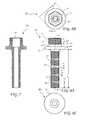
- FIG. 1is a perspective view of a light assembly according to the present invention.
- FIG. 2is a perspective view of the separate elements of the light assembly according to the present invention.
- FIG. 3is a perspective view of a light fixture mounting post according to the present invention.
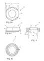
- FIG. 4Ais a side view of the light fixture mounting post attached to a light shade according to the present invention.
- FIG. 4Bis a top view of the light fixture mounting post attached to the light shade according to the present invention.
- FIG. 4Cis a bottom view of the light fixture mounting post attached to the light shade according to the present invention.
- FIG. 5shows a top view of a center of a light shade according to the present invention.
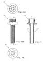
- FIG. 6Ais a side view of the light fixture mounting post alone according to the present invention.
- FIG. 6Bis a top view of the light fixture mounting post alone according to the present invention.
- FIG. 6Cis a bottom view of the light fixture mounting post alone according to the present invention.
- FIG. 7is a cross-sectional view of the light fixture mounting post according to the present invention taken along line 7 - 7 of FIG. 6A .
- FIG. 8Ais a side view of the light fixture mounting post nut according to the present invention.
- FIG. 8Bis a top view of the light fixture mounting post nut according to the present invention.
- FIG. 8Cis a bottom view of the light fixture mounting post nut according to the present invention.
- FIG. 9is a cross-sectional view of the light fixture mounting post nut according to the present invention taken along line 9 - 9 of FIG. 8A .
- FIG. 10Ais a side view of a second embodiment of the light fixture mounting post according to the present invention.
- FIG. 10Bis a top view of the second embodiment of the light fixture mounting post according to the present invention.
- FIG. 10Cis a bottom view of the second embodiment of the light fixture mounting post according to the present invention.
- FIG. 11is a cross-sectional view of the second embodiment of the light fixture mounting post according to the present invention taken along line 11 - 11 of FIG. 10A .
- FIG. 1A perspective view of a light assembly 10 according to the present invention is shown in FIG. 1 and a perspective view of the separate elements of the light assembly 10 is shown in FIG. 2 .
- the light assembly 10includes a light fixture mounting post nut 11 , an O-ring 12 , a shaped washer 13 , a light shade 14 , a light fixture mounting post 16 , and a light fixture 18 .
- the light shade 14includes a larger bowl shaped shading portion 14 a and a smaller upper attaching portion 14 b for attaching the light fixture mounting post 16 .
- the light fixture 18may be any fixture which may support a light and/or provide electrical connections to a light, or a second fixture which may support a light and/or provide electrical connections to a light.
- the light fixture mounting post 16includes an upper portion 20 for attaching to the attaching portion 14 b , a post flange 22 , and a lower portion for attaching the light fixture 18 .
- FIG. 4AA side view of the light fixture mounting post 16 attached to the attaching portion 14 b of the light shade 14 is shown in FIG. 4A
- a top view of the light fixture mounting post 16 attached to the attaching portion 14 bis shown in FIG. 4B
- a bottom view of the light fixture mounting post 16 attached to the attaching portion 14 bis shown in FIG. 4C
- a top view of a center portion of the lamp shadeis shown in FIG. 5 .
- the attaching portion 14 bincludes a non-round (for example, hexagonal) passage 15
- the light fixture mounting post 16includes a cooperating non-round (for example, hexagonal) shoulder 34 (see FIG. 6A ) on a flange 22 on the light fixture mounting post 16 .
- the shoulder 34engages the passage 15 to restrict or prevent rotation of the light fixture mounting post 16 once attached to the light shade 14 , for example, when the light fixture 18 is attached to or detached from the light fixture mounting post 16 .
- the shaped washer 13is sandwiched between the nut 11 and light shade 14 .
- the O-ring 12is concealed between the nut 11 and shaped washer 13 . While a hexagonal shaped shoulder 34 is preferred, any non-round shape may be sufficient to restrict rotation of the light fixture mounting post 16 .
- the mounting post 16includes a left hand threaded upper portion 20 and a lower portion 21 having spaced apart tapered pipe threaded segments 29 separated by spaces 28 .
- the lower portion 21also includes an unthreaded shoulder 30 adjacent to a space 28 for extending threaded segments 29 below the unthreaded shoulder 30 downward.
- the unthreaded shoulder 30provides additional length to the lower portion 21 which facilitates the attachment of known light fixtures.
- the spaces 28preferably have reduced thickness to allow easier shortening of the lower portion 21 .
- FIG. 6AA side view of the light fixture mounting post 16 , according to the present invention, is shown in FIG. 6A , a top view of the light fixture mounting post 16 is shown in FIG. 6B , a bottom view of the light fixture mounting post 16 is shown in FIG. 6C , and a cross-sectional view of the light fixture mounting post 16 taken along line 7 - 7 of FIG. 6A is shown in FIG. 7 .
- the flange 22positions the light shade 14 on the mounting post 16 and the hexagonal shoulder 34 is formed on the flange 22 .
- the mounting post 16includes left hand male threads T 1 and female threads T 2 on the upper portion 20 and male threads T 3 on the lower portion 21 .
- the threads T 1are preferably 3 ⁇ 4 inch or 7 ⁇ 8 inch National Pipe Thread (NPT) or National Pipe Straight (NPS).
- the threads T 2are preferably 1 ⁇ 2 inch or 3 ⁇ 4 inch and NPT or NPS by 14.
- the threads T 3are preferably 1 ⁇ 2 inch or 3 ⁇ 4 inch and NPT or NPS by 14.
- the lower portion 21has a length L 1
- the flange 22has a length L 2
- the hexagonal shoulder 34has a length L 3
- the threads T 1have a length L 4
- the spaces 28 between threaded segments 29have a length L 5
- the threaded segments 29have lengths L 6
- the unthreaded shoulder 30has a length L 7 .
- the hexagonal shoulder 34has a land width W 1
- the mounting post 16has an inside diameter D 1
- the flange 22has an outside diameter D 2 .
- the length L 1is preferably approximately 3.74 inches.
- the length L 2is preferably approximately 0.25 inches.
- the length L 3is preferably approximately 0.25 inches
- the length L 4is preferably approximately 0.575 inches
- the length L 5is preferably approximately 0.085 inches
- the length L 6is preferably approximately 0.66 inches
- the length L 7is preferably approximately 0.1445 inches
- the width W 1is preferably approximately 1.3172 inches
- the diameter D 1is preferably approximately 0.455 inches
- the diameter D 2is preferably approximately 1.3172 inches.
- FIG. 8AA side view of the light fixture mounting post nut 11 according to the present invention is shown in FIG. 8A , a top view of the light fixture mounting post nut 11 is shown in FIG. 8B , a bottom view of the light fixture mounting post nut 11 is shown in FIG. 8C , and a cross-sectional view of the light fixture mounting post nut 11 taken along line 9 - 9 of FIG. 8A is shown in FIG. 9 .
- the nut 11includes a nut flange 38 and a nut hexagonal portion 36 extending from the nut flange 38 .
- a nut recess 42is preferably provided on a bottom surface 40 of the nut 11 providing clearance for any portion of the hexagonal shoulder 34 reaching above the light shade 14 (see FIG. 2 ).
- the bottom surface 40further preferably includes an O-Ring recess 44 for accepting the O-Ring 12 (see FIG. 2 ).
- the post nut 11includes female threads T 4 for cooperating with male threads T 1 (see FIG
- the nut flange 38has a length L 8 and diameter D 3
- the nut hexagonal portion 36has a length L 9 and a land width W 2 .
- the length L 8is preferably approximately 0.177 inches
- the diameter D 3is preferably approximately 2.08 inches
- the length L 9is preferably approximately 0.391 inches
- the land width W 2is preferably approximately 1.8 inches.
- the nut recess 42had a length L 10 and a diameter D 4
- the O-Ring recess 44is preferably circular and has a semi-circular cross-section with a radius R.
- the length L 10is preferably approximately 0.25 inches
- the diameter D 4is preferably approximately 1.5 inches
- the radius Ris preferably approximately 0.05 inches.
- FIG. 10AA side view of a second embodiment of the light fixture mounting post 16 ′ according to the present invention is shown in FIG. 10A
- a top view of the light fixture mounting post 16 ′is shown in FIG. 10B
- a bottom view of the light fixture mounting post 16 ′is shown in FIG. 10C
- a cross-sectional view of the light fixture mounting post 16 ′ taken along line 11 - 11 of FIG. 10Ais shown in FIG. 11 .
- the light fixture mounting post 16is similar to the light fixture mounting post 16 except the lower portion 21 ′ is continuous with threads T 2 and T 4 described above.
Landscapes
- Engineering & Computer Science (AREA)
- General Engineering & Computer Science (AREA)
- Non-Portable Lighting Devices Or Systems Thereof (AREA)
Abstract
Description
Claims (6)
Priority Applications (2)
| Application Number | Priority Date | Filing Date | Title |
|---|---|---|---|
| US14/054,535US9234651B2 (en) | 2010-10-18 | 2013-10-15 | Lighting fixture mounting post |
| US14/980,062US9958141B2 (en) | 2010-10-18 | 2015-12-28 | Lighting fixture mounting post |
Applications Claiming Priority (2)
| Application Number | Priority Date | Filing Date | Title |
|---|---|---|---|
| US12/906,404US8556477B2 (en) | 2010-10-18 | 2010-10-18 | Lighting fixture mounting post |
| US14/054,535US9234651B2 (en) | 2010-10-18 | 2013-10-15 | Lighting fixture mounting post |
Related Parent Applications (1)
| Application Number | Title | Priority Date | Filing Date |
|---|---|---|---|
| US12/906,404Continuation-In-PartUS8556477B2 (en) | 2010-10-18 | 2010-10-18 | Lighting fixture mounting post |
Related Child Applications (1)
| Application Number | Title | Priority Date | Filing Date |
|---|---|---|---|
| US14/980,062Continuation-In-PartUS9958141B2 (en) | 2010-10-18 | 2015-12-28 | Lighting fixture mounting post |
Publications (2)
| Publication Number | Publication Date |
|---|---|
| US20140119030A1 US20140119030A1 (en) | 2014-05-01 |
| US9234651B2true US9234651B2 (en) | 2016-01-12 |
Family
ID=50547008
Family Applications (1)
| Application Number | Title | Priority Date | Filing Date |
|---|---|---|---|
| US14/054,535Expired - Fee RelatedUS9234651B2 (en) | 2010-10-18 | 2013-10-15 | Lighting fixture mounting post |
Country Status (1)
| Country | Link |
|---|---|
| US (1) | US9234651B2 (en) |
Cited By (2)
| Publication number | Priority date | Publication date | Assignee | Title |
|---|---|---|---|---|
| US20160109101A1 (en)* | 2010-10-18 | 2016-04-21 | Jeffrey Ohai | Lighting Fixture Mounting Post |
| US10302120B2 (en) | 2015-12-21 | 2019-05-28 | Barn Light Electric Company, LLC | Fixture connection device |
Families Citing this family (2)
| Publication number | Priority date | Publication date | Assignee | Title |
|---|---|---|---|---|
| WO2018080828A1 (en)* | 2016-10-28 | 2018-05-03 | Alter Bee Corporation | Improved light assembly and alignment device |
| US12085265B2 (en)* | 2022-02-17 | 2024-09-10 | Litek America Corp. | Led lighting system for retrofitting existing lantern-style lamps |
Citations (13)
| Publication number | Priority date | Publication date | Assignee | Title |
|---|---|---|---|---|
| US1882312A (en) | 1930-03-29 | 1932-10-11 | Aspinwall Robert Sayer | Canopy stem |
| US1985582A (en) | 1932-05-28 | 1934-12-25 | Crescent Brass Mfg Co Inc | Fixture hanger |
| US2111357A (en) | 1936-07-15 | 1938-03-15 | American Radiator Co | Pipe hanger |
| US2446736A (en) | 1945-09-27 | 1948-08-10 | Day Brite Lighting Inc | Suspension support for electric lighting fixtures |
| US5584559A (en) | 1993-08-12 | 1996-12-17 | Koito Manufacturing Co., Ltd. | Headlamp for a motor vehicle |
| US5690424A (en) | 1995-05-08 | 1997-11-25 | Justice Design Group, Inc. | Mounting apparatus for lighting fixtures |
| US5845882A (en) | 1996-09-27 | 1998-12-08 | Hodges; B. Eugene | Staple hook pipe hanger |
| US6538201B1 (en)* | 2001-12-26 | 2003-03-25 | Arlington Industries, Inc | Threaded snap in connector |
| US6547413B2 (en) | 2001-03-23 | 2003-04-15 | Ming-Hua Hung | Built-in lamp apparatus for suspended ceilings |
| US6679620B2 (en) | 2002-04-12 | 2004-01-20 | Hunter Fan Company | Light fixture |
| US20040165394A1 (en) | 2003-02-25 | 2004-08-26 | Pusch Allen A. | Outdoor light mounting system |
| US7401950B2 (en) | 2005-12-22 | 2008-07-22 | Eclairage Contraste | Assembly for vertically positioning a lamp-shade |
| US20120092881A1 (en)* | 2010-10-18 | 2012-04-19 | Jeffrey Ohai | Lighting Fixture Mounting Post |
- 2013
- 2013-10-15USUS14/054,535patent/US9234651B2/ennot_activeExpired - Fee Related
Patent Citations (14)
| Publication number | Priority date | Publication date | Assignee | Title |
|---|---|---|---|---|
| US1882312A (en) | 1930-03-29 | 1932-10-11 | Aspinwall Robert Sayer | Canopy stem |
| US1985582A (en) | 1932-05-28 | 1934-12-25 | Crescent Brass Mfg Co Inc | Fixture hanger |
| US2111357A (en) | 1936-07-15 | 1938-03-15 | American Radiator Co | Pipe hanger |
| US2446736A (en) | 1945-09-27 | 1948-08-10 | Day Brite Lighting Inc | Suspension support for electric lighting fixtures |
| US5584559A (en) | 1993-08-12 | 1996-12-17 | Koito Manufacturing Co., Ltd. | Headlamp for a motor vehicle |
| US5690424A (en) | 1995-05-08 | 1997-11-25 | Justice Design Group, Inc. | Mounting apparatus for lighting fixtures |
| US5845882A (en) | 1996-09-27 | 1998-12-08 | Hodges; B. Eugene | Staple hook pipe hanger |
| US6547413B2 (en) | 2001-03-23 | 2003-04-15 | Ming-Hua Hung | Built-in lamp apparatus for suspended ceilings |
| US6538201B1 (en)* | 2001-12-26 | 2003-03-25 | Arlington Industries, Inc | Threaded snap in connector |
| US6679620B2 (en) | 2002-04-12 | 2004-01-20 | Hunter Fan Company | Light fixture |
| US20040165394A1 (en) | 2003-02-25 | 2004-08-26 | Pusch Allen A. | Outdoor light mounting system |
| US7401950B2 (en) | 2005-12-22 | 2008-07-22 | Eclairage Contraste | Assembly for vertically positioning a lamp-shade |
| US20120092881A1 (en)* | 2010-10-18 | 2012-04-19 | Jeffrey Ohai | Lighting Fixture Mounting Post |
| US8556477B2 (en) | 2010-10-18 | 2013-10-15 | Jeffrey Ohai | Lighting fixture mounting post |
Cited By (3)
| Publication number | Priority date | Publication date | Assignee | Title |
|---|---|---|---|---|
| US20160109101A1 (en)* | 2010-10-18 | 2016-04-21 | Jeffrey Ohai | Lighting Fixture Mounting Post |
| US9958141B2 (en)* | 2010-10-18 | 2018-05-01 | Jeffrey Ohai | Lighting fixture mounting post |
| US10302120B2 (en) | 2015-12-21 | 2019-05-28 | Barn Light Electric Company, LLC | Fixture connection device |
Also Published As
| Publication number | Publication date |
|---|---|
| US20140119030A1 (en) | 2014-05-01 |
Similar Documents
| Publication | Publication Date | Title |
|---|---|---|
| US9958141B2 (en) | Lighting fixture mounting post | |
| US8556477B2 (en) | Lighting fixture mounting post | |
| US10670203B1 (en) | Modular light fixture with interchangeable components | |
| US10711984B2 (en) | Landscape lighting fixture and mount system | |
| US9234651B2 (en) | Lighting fixture mounting post | |
| CN102410480B (en) | Lighting, method of hanging multiple light sources | |
| US9291188B2 (en) | Mounting fixture and method for using same | |
| CA2674596A1 (en) | Adapter assembly for pole luminaire | |
| US9541264B2 (en) | Light-emitting diode (LED) lighting fixture | |
| RU93932U1 (en) | DEVICE FOR MOUNTING A POINT LUMINAIRE IN A STRETCH CEILING | |
| JP4632054B2 (en) | lighting equipment | |
| US7762695B2 (en) | Light fixture coupling system | |
| US20110047896A1 (en) | Centering ground spike for supporting a vertical pole | |
| US9488343B2 (en) | Interchangeable lighting assembly | |
| US10302120B2 (en) | Fixture connection device | |
| CN104676395A (en) | Ceiling lamp with adjustable bracket | |
| CN200982567Y (en) | Simple wall-mounted skylight | |
| US10443830B2 (en) | Light socket adapter | |
| US7798683B2 (en) | Torchiere floor lamp having hidden light | |
| CN206310379U (en) | Pendent lamp | |
| EP2757309A2 (en) | Light-emitting diode and lamp with at least one light-emitting diode module | |
| KR200239552Y1 (en) | A facilities fixed post | |
| JP2018186710A (en) | Illumination device for plant cultivation | |
| KR200418692Y1 (en) | Street light cover | |
| CN219623913U (en) | Radial lamp |
Legal Events
| Date | Code | Title | Description |
|---|---|---|---|
| STCF | Information on status: patent grant | Free format text:PATENTED CASE | |
| IPR | Aia trial proceeding filed before the patent and appeal board: inter partes review | Free format text:TRIAL NO: IPR2017-00145 Opponent name:BARN LIGHT ELECTRIC COMPANY LLC Effective date:20161118 | |
| FPB1 | Reexamination decision cancelled all claims | Kind code of ref document:C1 Free format text:REEXAMINATION CERTIFICATE Effective date:20171129 | |
| IPRC | Trial and appeal board: inter partes review certificate | Kind code of ref document:K1 Owner name:JEFFREY OHAI Free format text:INTER PARTES REVIEW CERTIFICATE; TRIAL NO. IPR2017-00145, NOV. 18, 2016 INTER PARTES REVIEW CERTIFICATE; TRIAL NO. IPR2017-00145, NOV. 18, 2016 Opponent name:BARN LIGHT ELECTRIC COMPANY, LLC Effective date:20180112 | |
| FEPP | Fee payment procedure | Free format text:MAINTENANCE FEE REMINDER MAILED (ORIGINAL EVENT CODE: REM.); ENTITY STATUS OF PATENT OWNER: SMALL ENTITY | |
| LAPS | Lapse for failure to pay maintenance fees | Free format text:PATENT EXPIRED FOR FAILURE TO PAY MAINTENANCE FEES (ORIGINAL EVENT CODE: EXP.); ENTITY STATUS OF PATENT OWNER: SMALL ENTITY | |
| STCH | Information on status: patent discontinuation | Free format text:PATENT EXPIRED DUE TO NONPAYMENT OF MAINTENANCE FEES UNDER 37 CFR 1.362 | |
| FP | Lapsed due to failure to pay maintenance fee | Effective date:20200112 |