US9234406B2 - Seat assembly with counter for isolating fracture zones in a well - Google Patents
Seat assembly with counter for isolating fracture zones in a wellDownload PDFInfo
- Publication number
- US9234406B2 US9234406B2US14/666,977US201514666977AUS9234406B2US 9234406 B2US9234406 B2US 9234406B2US 201514666977 AUS201514666977 AUS 201514666977AUS 9234406 B2US9234406 B2US 9234406B2
- Authority
- US
- United States
- Prior art keywords
- seat structure
- annular seat
- tubular
- diameter
- plug
- Prior art date
- Legal status (The legal status is an assumption and is not a legal conclusion. Google has not performed a legal analysis and makes no representation as to the accuracy of the status listed.)
- Expired - Fee Related
Links
- 238000000034methodMethods0.000claimsabstractdescription16
- 238000011144upstream manufacturingMethods0.000claimsdescription16
- 239000012530fluidSubstances0.000claimsdescription9
- 230000000903blocking effectEffects0.000claims4
- 230000002093peripheral effectEffects0.000claims4
- 239000012858resilient materialSubstances0.000claims2
- 239000007769metal materialSubstances0.000claims1
- 238000010276constructionMethods0.000abstract1
- 230000002596correlated effectEffects0.000abstract1
- 208000010392Bone FracturesDiseases0.000description51
- 206010017076FractureDiseases0.000description51
- 230000007246mechanismEffects0.000description13
- 239000002131composite materialSubstances0.000description10
- 239000000463materialSubstances0.000description10
- 230000008569processEffects0.000description6
- 238000003801millingMethods0.000description4
- 238000010926purgeMethods0.000description4
- 238000004519manufacturing processMethods0.000description3
- 230000000638stimulationEffects0.000description3
- 229910001018Cast ironInorganic materials0.000description2
- 238000012986modificationMethods0.000description2
- 230000004048modificationEffects0.000description2
- 238000012856packingMethods0.000description2
- 238000006467substitution reactionMethods0.000description2
- 208000006670Multiple fracturesDiseases0.000description1
- 208000002565Open FracturesDiseases0.000description1
- 238000009825accumulationMethods0.000description1
- XAGFODPZIPBFFR-UHFFFAOYSA-NaluminiumChemical compound[Al]XAGFODPZIPBFFR-UHFFFAOYSA-N0.000description1
- 229910052782aluminiumInorganic materials0.000description1
- 238000013459approachMethods0.000description1
- 230000000712assemblyEffects0.000description1
- 238000000429assemblyMethods0.000description1
- 230000015572biosynthetic processEffects0.000description1
- 239000004568cementSubstances0.000description1
- 230000008859changeEffects0.000description1
- 230000006835compressionEffects0.000description1
- 238000007906compressionMethods0.000description1
- 239000000356contaminantSubstances0.000description1
- 238000005553drillingMethods0.000description1
- 230000005484gravityEffects0.000description1
- 229930195733hydrocarbonNatural products0.000description1
- 150000002430hydrocarbonsChemical class0.000description1
- 230000013011matingEffects0.000description1
- 230000000717retained effectEffects0.000description1
- 239000004576sandSubstances0.000description1
- 230000001360synchronised effectEffects0.000description1
Images


Classifications
- E—FIXED CONSTRUCTIONS
- E21—EARTH OR ROCK DRILLING; MINING
- E21B—EARTH OR ROCK DRILLING; OBTAINING OIL, GAS, WATER, SOLUBLE OR MELTABLE MATERIALS OR A SLURRY OF MINERALS FROM WELLS
- E21B34/00—Valve arrangements for boreholes or wells
- E21B34/06—Valve arrangements for boreholes or wells in wells
- E21B34/14—Valve arrangements for boreholes or wells in wells operated by movement of tools, e.g. sleeve valves operated by pistons or wire line tools
- E21B34/142—Valve arrangements for boreholes or wells in wells operated by movement of tools, e.g. sleeve valves operated by pistons or wire line tools unsupported or free-falling elements, e.g. balls, plugs, darts or pistons
- E—FIXED CONSTRUCTIONS
- E21—EARTH OR ROCK DRILLING; MINING
- E21B—EARTH OR ROCK DRILLING; OBTAINING OIL, GAS, WATER, SOLUBLE OR MELTABLE MATERIALS OR A SLURRY OF MINERALS FROM WELLS
- E21B34/00—Valve arrangements for boreholes or wells
- E21B34/06—Valve arrangements for boreholes or wells in wells
- E21B34/14—Valve arrangements for boreholes or wells in wells operated by movement of tools, e.g. sleeve valves operated by pistons or wire line tools
- E—FIXED CONSTRUCTIONS
- E21—EARTH OR ROCK DRILLING; MINING
- E21B—EARTH OR ROCK DRILLING; OBTAINING OIL, GAS, WATER, SOLUBLE OR MELTABLE MATERIALS OR A SLURRY OF MINERALS FROM WELLS
- E21B33/00—Sealing or packing boreholes or wells
- E21B33/10—Sealing or packing boreholes or wells in the borehole
- E21B33/12—Packers; Plugs
- E21B33/128—Packers; Plugs with a member expanded radially by axial pressure
- E—FIXED CONSTRUCTIONS
- E21—EARTH OR ROCK DRILLING; MINING
- E21B—EARTH OR ROCK DRILLING; OBTAINING OIL, GAS, WATER, SOLUBLE OR MELTABLE MATERIALS OR A SLURRY OF MINERALS FROM WELLS
- E21B33/00—Sealing or packing boreholes or wells
- E21B33/10—Sealing or packing boreholes or wells in the borehole
- E21B33/13—Methods or devices for cementing, for plugging holes, crevices or the like
- E21B33/134—Bridging plugs
- E—FIXED CONSTRUCTIONS
- E21—EARTH OR ROCK DRILLING; MINING
- E21B—EARTH OR ROCK DRILLING; OBTAINING OIL, GAS, WATER, SOLUBLE OR MELTABLE MATERIALS OR A SLURRY OF MINERALS FROM WELLS
- E21B43/00—Methods or apparatus for obtaining oil, gas, water, soluble or meltable materials or a slurry of minerals from wells
- E21B43/14—Obtaining from a multiple-zone well
- E—FIXED CONSTRUCTIONS
- E21—EARTH OR ROCK DRILLING; MINING
- E21B—EARTH OR ROCK DRILLING; OBTAINING OIL, GAS, WATER, SOLUBLE OR MELTABLE MATERIALS OR A SLURRY OF MINERALS FROM WELLS
- E21B43/00—Methods or apparatus for obtaining oil, gas, water, soluble or meltable materials or a slurry of minerals from wells
- E21B43/25—Methods for stimulating production
- E21B43/26—Methods for stimulating production by forming crevices or fractures
- E21B43/261—Separate steps of (1) cementing, plugging or consolidating and (2) fracturing or attacking the formation
- E21B2034/007—
- E—FIXED CONSTRUCTIONS
- E21—EARTH OR ROCK DRILLING; MINING
- E21B—EARTH OR ROCK DRILLING; OBTAINING OIL, GAS, WATER, SOLUBLE OR MELTABLE MATERIALS OR A SLURRY OF MINERALS FROM WELLS
- E21B2200/00—Special features related to earth drilling for obtaining oil, gas or water
- E21B2200/06—Sleeve valves
Definitions
- the present inventionrelates to a fracture plug seat assembly used in well stimulation for engaging and creating a seal when a plug, such as a ball, is dropped into a wellbore and landed on the fracture plug seat assembly for isolating fracture zones in a well. More particularly, the present invention relates to a fracture plug seat assembly that includes a mechanical counter allowing plugs to pass through the seat then locking to a rigid seat position after a designated number of plugs from the surface have passed through the seat. The locking mechanism disengages when flow is reversed and plugs are purged.
- Zone fracturinghelps stimulate the well by creating conduits from the formation for the hydrocarbons to reach the well.
- Many gas wellsare drilled for zone fracturing with a system called a ball drop system planned at the well's inception.
- a well with a ball drop systemwill be equipped with a string of piping below the cemented casing portion of the well. The string is segmented with packing elements, fracture plugs and fracture plug seat assemblies to isolate zones.
- a fracture plugsuch as a ball or other suitably shaped structure (hereinafter referred to collectively as a “ball”) is dropped or pumped down the well and seats on the fracture plug seat assembly, thereby isolating pressure from above.
- ballsuitably shaped structure
- a fracture plug seat assemblytypically includes a fracture plug seat having an axial opening of a select diameter. To the extent multiple fracture plugs are disposed along a string, the diameter of the axial opening of the respective fracture plug seats becomes progressively smaller with the depth of the string. This permits a plurality of balls having a progressively increasing diameter, to be dropped (or pumped), smallest to largest diameter, down the well to isolate the various zones, starting from the toe of the well and moving up.
- a large orifice through an open seatis desired while fracing zones below that seat.
- An unwanted consequence of having seats incrementally smaller as they approach the toeis the existence of pressure loss across the smaller seats. The pressure loss reduces the efficiency of the system and creates flow restrictions while fracing and during well production.
- the difference in the diameter of the axial opening of adjacent fracture plug seats and the diameter of the balls designed to be caught by such fracture plug seatsis very small, and the consequent surface area of contact between the ball and its seat is very small. Due to the high pressure that impacts the balls during a hydraulic fracturing process, the balls often become stuck and are difficult to purge when fracing is complete and the well pressure reverses the flow and produces to the surface. If a ball is stuck in the seat and cannot be purged, the ball(s) must be removed from the string by costly and time-consuming milling or drilling processes.
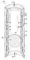
- FIG. 1illustrates a prior art fracture plug seat assembly 10 disposed along a tubing string 12 .
- Fracture plug seat assembly 10includes a metallic, high strength composite or other rigid material seat 14 mounted on a sliding sleeve 16 which is movable between a first position and a second position. In the first position shown in FIG. 1 , sleeve 16 is disposed to inhibit fluid flow through radial ports 18 from annulus 20 into the interior of tubing string 12 .
- Packing element 24is disposed along tubing string 12 to restrict fluid flow in the annulus 20 formed between the earth 26 and the tubing string 12 .
- FIG. 2illustrates the prior art fracture plug seat assembly 10 of FIG. 1 , but with a ball 28 landed on the metallic, high strength composite or other rigid material seat 14 and with sliding sleeve 16 in the second position.
- fluid pressure 30 applied from uphole of fracture plug seat assembly 10urges sliding sleeve 16 into the second position shown in FIG. 2 , thereby exposing radial ports 18 to permit fluid flow therethrough, diverting the flow to the annulus 20 formed between the earth 26 and the tubing string 12 .
- the metallic, high strength composite or other rigid material seat 14has a tapered surface 32 that forms an inverted cone for the ball or fracture plug 28 to land upon. This helps translate the load on the ball 28 from shear into compression, thereby deforming the ball 28 into the metallic, high strength composite or other rigid material seat 14 to form a seal.
- the surface of such metallic, high strength composite or other rigid material seats 14have been contoured to match the shape of the ball or fracture plug 28 .
- One drawback of such metallic, high strength composite or other rigid material seats 14is that high stress concentrations in the seat 14 are transmitted to the ball or fracture plug 28 . For various reasons, including specific gravity and ease of milling, balls or fracture plugs 28 are often made of a composite plastic or aluminum.
- fracture plug seat assembly designsinclude mechanisms that are actuated by sliding pistons and introduce an inward pivoting mechanical support beneath the ball. These designs also have a metallic, high strength composite or other rigid material seat, but are provided with additional support from the support mechanism. These fracture plug seat assembly designs can be described as having a normally open seat that closes when a ball or fracture plug is landed upon the seat. Such normally open fracture plug seat assembly designs suffer when contaminated with the heavy presence of sand and cement. They also rely upon incrementally sized balls so such systems suffer from flow restriction and require post frac milling.
- FIG. 1illustrates a prior art fracture plug seat assembly positioned in a well bore.
- FIG. 2illustrates the prior art fracture plug seat assembly of FIG. 1 with a ball landed on the seat of the fracture plug seat assembly.
- FIG. 3illustrates a cross-section of a fracture plug seat assembly incorporating an embodiment of the present invention with a cam driven rotating counter in the unlocked position.
- FIG. 4illustrates a cross-section of the fracture plug seat assembly illustrated in FIG. 3 with a ball passing through the assembly and actuating an expandable seat.
- FIG. 5illustrates a side view of an embodiment of a counting mechanism of the present invention for use in a fracture plug seat assembly with a semi-translucent counting ring.
- FIG. 6illustrates an isometric view of an embodiment of a counting ring of the present invention for use in a fracture plug seat assembly.
- FIG. 7illustrates a side view of the embodiment of a counting mechanism of the present invention illustrated in FIG. 5 with the components in position to actuate the counter.
- FIG. 8illustrates a side view of the embodiment of a counting mechanism of the present invention illustrated in FIG. 5 with a locking ring in a locked position.
- FIG. 9illustrates a cross-section of the fracture plug seat assembly illustrated in FIG. 3 with a locking ring in a locked position.
- FIG. 10illustrates a cross-section of the fracture plug seat assembly illustrated in FIG. 9 with a ball plugging the seat.
- FIG. 11illustrates a cross-section of the fracture plug seat assembly illustrated in FIG. 9 with a ball purging to the surface.
- FIG. 12is a cross-section of a fracture plug seat assembly of the present invention.
- the method and apparatus of the present inventionprovides a fracture plug seat assembly used in well stimulation for engaging and creating a seal when a plug, such as a ball, is dropped into a wellbore and landed on the fracture plug seat assembly for isolating fracture zones in a well.
- the fracture plug seat assemblyhas a fracture plug seat that includes an expandable ring that enables the seat to expand when a ball passes through and actuates a counting mechanism so that balls are allowed to pass until the counting mechanism reaches a predetermined position which will enable the actuation of a locking mechanism.
- the locking mechanismprevents expansion of the seat when the next ball lands on the seat and pressure is applied from the upstream direction.
- the seatis free to disengage from the locking mechanism and allow expansion and hence, balls that had previously passed through the seat pass through from downstream and return to the surface.
- all ballshave the same size and, therefore, flow restriction is greatly reduced at the lower zones, since the seat orifices do not become incrementally smaller.
- the fracture plug seat assembly of the present inventionwhen dropping balls from the surface, it is not required to drop sequential ball sizes which eliminates a potential source of errors.
- only one size of seat assembly and ballmust be manufactured, instead of sometimes 40 different sizes, making manufacturing more cost effective.
- the resulting production flow from the stringcan eliminate the need to mill out the seats.
- FIG. 3illustrates a cross-section of a fracture plug seat assembly incorporating an embodiment of the present invention.
- sliding sleeve assembly 40is illustrated in a position to receive balls which will pass through and be counted.
- Sliding sleeve 41is sealably retained within a tubing string.
- a segmented expandable seat assembly 42is in a first closed position and positioned between a lower seat nut 43 and an upper piston 44 .
- the lower seat nut 43is threadably connected to and does not move relative to the sliding sleeve 41 .
- the upper piston 44is biased in the downstream direction 51 against the seat assembly 42 by a spring 46 .
- the spring 46engages a shoulder 45 on the sliding sleeve 41 .
- FIG. 4illustrates the fracture plug seat assembly of FIG. 3 with a ball 50 passing through the sliding sleeve assembly 40 in the direction 51 with the direction of flow moving upstream to downstream.
- the ball 50is engaged with the expandable seat assembly 42 and has driven the seat radially outward into a pocket 52 of a locking ring 53 .
- the upper piston 44is wedged to move in the upstream direction 54 and further compresses the spring 46 .
- the upper piston 44moves in the upstream direction 54 it actuates a counting ring 55 via radial pins 56 which are rigidly connected to the upper piston 44 by engaging a cam surface 57 located on the end of the counting ring 55 .
- FIG. 5illustrates an embodiment for actuating the counting ring 55 .
- the counting ring 55which is shouldered axially to the sliding sleeve 41 is forced to rotate as the radial pins 56 slide along the cam surface 57 .
- the spring 46forces the upper piston 44 to return to the position shown in FIG. 3 .
- a second set of radial pins 58engages a cam surface 59 on the upstream end of the counting ring 55 and force further rotation of the counting ring 55 by sliding across the cam surface 59 .
- axial pin(s) 61prevent the counting ring 55 from moving in the downstream direction since they are rigidly connected to the locking ring 53 which is biased in the upstream direction 54 by spring 63 ( FIG. 3 ).
- FIG. 6illustrates an isometric view of the downstream side of counting ring 55 .
- counting ring 55has two synchronized sets of cam surfaces 57 , each set spanning nearly 180 degrees.
- Two holes 60are located in the downstream face of the counting ring 55 .
- a partially translucent counting ring 55is shown in a side view with a radial pin 56 engaging a cam surface 57 .
- yet another radial pin 64keeps the locking ring 53 from rotating relative to the upper piston 44 .
- FIG. 7is consistent with the position shown in FIG. 4 . Further, as shown in FIG.
- an axial pin 61is fixed to the locking ring 53 and slides across the smooth surface 62 of counting ring 55 ( FIG. 6 ).
- An additional axial pinis diametrically opposite the axial pin 61 and is fixed to the locking ring 53 and slides across the smooth surface 62 of counting ring 55 .
- FIG. 9shows the sliding sleeve assembly 40 in the position where the locking ring 53 has shifted upstream and is in contact with the counting ring 55 .
- the pocket 52is no longer in a position to allow expansion of the expandable seat assembly 42 from a ball passing in the direction 51 .
- FIG. 10illustrates the sliding sleeve assembly 40 with a ball 70 that has landed on the expandable seat assembly 42 when the locking ring 53 is in the locked position.
- the expandable seat assembly 42is restricted from expanding due to the locking ring 53 and hence the ball 70 cannot pass in the downstream direction 51 .
- a seal 71can assist in preventing fluid from passing by the ball 70 in the downstream direction 51 and a seal 73 prevents fluid from passing between the upper piston 44 and the sliding sleeve 41 .
- Pressure applied to the ball in the downstream direction 51results in the force necessary to actuate the sliding sleeve assembly 40 to an opened position so its corresponding zone can be fractured.
- FIG. 11illustrates a ball 72 that had previous passed through the sliding sleeve assembly 40 in the downstream direction 51 and actuated the counting ring 55 .
- Now pressure from the downstream side of the ball 72forces the expandable seat assembly 42 to slide in the upstream direction 54 until it reaches the pocket 52 .
- Ball 72can now pass through the expandable seat assembly 40 and freely purge to the surface.
- FIG. 12is a cross-section of a fracture plug seat assembly of the present invention in a position ready to count a ball.
- an upper wave spring 83which helically spirals around axis 84 , biases an upper piston 81 in the downstream direction 51 .
- a wave spring 85 similar to the upper wave spring 83biases a locking ring 82 in the upstream direction 54 .
- An expandable seat assembly 94is clamped by the biased upper piston 81 and a lower seat nut 93 into a cinched position. The expandable seat assembly 94 is free to expand into a pocket 95 when a ball passes through.
- the upper piston 81When a ball actuates the expandable seat assembly 94 , the upper piston 81 carries radial pins 96 into a cam profile of counting ring 97 to initiate rotation of the counting ring 97 . After the final ball to be counted passes through the expandable seat assembly 94 , an axial pin 98 falls into a mating hole in counting ring 97 and the locking ring 82 is free to be pushed in the upstream direction 54 by the wave spring 85 .
- FIG. 12Also illustrated in FIG. 12 are an upper wiper seal 86 , a lower seal 87 and a nut seal 88 .
- both upper wiper seal 86 and lower seal 87engage the upper piston 81 at the same diameter so there is no change in volume in annulus 89 when the upper piston 81 is actuated. While not essential to the function of this embodiment of the fracture plug seat assembly, this embodiment resists the accumulation of dirty fluid in the annulus 89 .
- the nut seal 88guards against the incursion of debris into the space 91 .
- Expandable seat assembly 94may be formed from any suitable material such as a segmented ring of drillable cast iron.
- the expandable seat assembly 94may also be encapsulated in rubber so as to guard against the entry of contaminants into pocket 95 and to shield the cast iron from the abrasive fluid passing through the expandable seat assembly 94 .
- the means to actuate the countercould be a lever or radial piston that is not integrated into the expandable seat. It is convenient to use the expandable seat as the mechanism to actuate the counter. It is also to be understood that the counter could actuate a collapsible seat.
- the elements and teachings of the various illustrative exemplary embodimentsmay be combined in whole or in part in some or all of the illustrative exemplary embodiments.
- one or more of the elements and teachings of the various illustrative exemplary embodimentsmay be omitted, at least in part, and/or combined, at least in part, with one or more of the other elements and teachings of the various illustrative embodiments.
- any spatial referencessuch as, for example, “upper,” “lower,” “above,” “below,” “between,” “bottom,” “vertical,” “horizontal,” “angular,” “upwards,” “downwards,” “side-to-side,” “left-to-right,” “left,” “right,” “right-to-left,” “top-to-bottom,” “bottom-to-top,” “top,” “bottom,” “bottom-up,” “top-down,” etc., are for the purpose of illustration only and do not limit the specific orientation or location of the structure described above.
- steps, processes, and proceduresare described as appearing as distinct acts, one or more of the steps, one or more of the processes, and/or one or more of the procedures may also be performed in different orders, simultaneously and/or sequentially.
- the steps, processes and/or proceduresmay be merged into one or more steps, processes and/or procedures.
- one or more of the operational steps in each embodimentmay be omitted.
- some features of the present disclosuremay be employed without a corresponding use of the other features.
- one or more of the above-described embodiments and/or variationsmay be combined in whole or in part with any one or more of the other above-described embodiments and/or variations.
Landscapes
- Life Sciences & Earth Sciences (AREA)
- Engineering & Computer Science (AREA)
- Geology (AREA)
- Mining & Mineral Resources (AREA)
- Physics & Mathematics (AREA)
- Environmental & Geological Engineering (AREA)
- Fluid Mechanics (AREA)
- General Life Sciences & Earth Sciences (AREA)
- Geochemistry & Mineralogy (AREA)
- Quick-Acting Or Multi-Walled Pipe Joints (AREA)
- Seats For Vehicles (AREA)
- Sealing Devices (AREA)
Abstract
Description
Claims (16)
Priority Applications (1)
| Application Number | Priority Date | Filing Date | Title |
|---|---|---|---|
| US14/666,977US9234406B2 (en) | 2012-05-09 | 2015-03-24 | Seat assembly with counter for isolating fracture zones in a well |
Applications Claiming Priority (3)
| Application Number | Priority Date | Filing Date | Title |
|---|---|---|---|
| US201261644887P | 2012-05-09 | 2012-05-09 | |
| US13/887,779US9353598B2 (en) | 2012-05-09 | 2013-05-06 | Seat assembly with counter for isolating fracture zones in a well |
| US14/666,977US9234406B2 (en) | 2012-05-09 | 2015-03-24 | Seat assembly with counter for isolating fracture zones in a well |
Related Parent Applications (1)
| Application Number | Title | Priority Date | Filing Date |
|---|---|---|---|
| US13/887,779ContinuationUS9353598B2 (en) | 2012-05-09 | 2013-05-06 | Seat assembly with counter for isolating fracture zones in a well |
Publications (2)
| Publication Number | Publication Date |
|---|---|
| US20150191998A1 US20150191998A1 (en) | 2015-07-09 |
| US9234406B2true US9234406B2 (en) | 2016-01-12 |
Family
ID=49547757
Family Applications (3)
| Application Number | Title | Priority Date | Filing Date |
|---|---|---|---|
| US13/887,779Expired - Fee RelatedUS9353598B2 (en) | 2012-05-09 | 2013-05-06 | Seat assembly with counter for isolating fracture zones in a well |
| US14/666,977Expired - Fee RelatedUS9234406B2 (en) | 2012-05-09 | 2015-03-24 | Seat assembly with counter for isolating fracture zones in a well |
| US15/145,927AbandonedUS20160245043A1 (en) | 2012-05-09 | 2016-05-04 | Seat assembly with counter for isolating fracture zones in a well |
Family Applications Before (1)
| Application Number | Title | Priority Date | Filing Date |
|---|---|---|---|
| US13/887,779Expired - Fee RelatedUS9353598B2 (en) | 2012-05-09 | 2013-05-06 | Seat assembly with counter for isolating fracture zones in a well |
Family Applications After (1)
| Application Number | Title | Priority Date | Filing Date |
|---|---|---|---|
| US15/145,927AbandonedUS20160245043A1 (en) | 2012-05-09 | 2016-05-04 | Seat assembly with counter for isolating fracture zones in a well |
Country Status (5)
| Country | Link |
|---|---|
| US (3) | US9353598B2 (en) |
| EP (1) | EP2847419A4 (en) |
| AU (1) | AU2013259727B2 (en) |
| CA (1) | CA2869793C (en) |
| WO (1) | WO2013169790A1 (en) |
Cited By (3)
| Publication number | Priority date | Publication date | Assignee | Title |
|---|---|---|---|---|
| US9556704B2 (en) | 2012-09-06 | 2017-01-31 | Utex Industries, Inc. | Expandable fracture plug seat apparatus |
| US10337288B2 (en)* | 2015-06-10 | 2019-07-02 | Weatherford Technology Holdings, Llc | Sliding sleeve having indexing mechanism and expandable sleeve |
| US20220136368A1 (en)* | 2020-10-30 | 2022-05-05 | Baker Hughes Oilfield Operations Llc | Indexing tool system for a resource exploration and recovery system |
Families Citing this family (38)
| Publication number | Priority date | Publication date | Assignee | Title |
|---|---|---|---|---|
| CA2813645C (en) | 2010-10-06 | 2019-10-29 | Packers Plus Energy Services Inc. | Actuation dart for wellbore operations, wellbore treatment apparatus and method |
| US9121248B2 (en)* | 2011-03-16 | 2015-09-01 | Raymond Hofman | Downhole system and apparatus incorporating valve assembly with resilient deformable engaging element |
| WO2012118889A2 (en)* | 2011-03-02 | 2012-09-07 | Team Oil Tools, Lp | Multi-actuating seat and drop element |
| US9909384B2 (en) | 2011-03-02 | 2018-03-06 | Team Oil Tools, Lp | Multi-actuating plugging device |
| WO2013016822A1 (en) | 2011-07-29 | 2013-02-07 | Packers Plus Energy Services Inc. | Wellbore tool with indexing mechanism and method |
| EP2766561A4 (en)* | 2011-10-11 | 2015-11-18 | Packers Plus Energy Serv Inc | Wellbore actuators, treatment strings and methods |
| US8950496B2 (en)* | 2012-01-19 | 2015-02-10 | Baker Hughes Incorporated | Counter device for selectively catching plugs |
| US9187978B2 (en)* | 2013-03-11 | 2015-11-17 | Weatherford Technology Holdings, Llc | Expandable ball seat for hydraulically actuating tools |
| US9458698B2 (en) | 2013-06-28 | 2016-10-04 | Team Oil Tools Lp | Linearly indexing well bore simulation valve |
| US10422202B2 (en) | 2013-06-28 | 2019-09-24 | Innovex Downhole Solutions, Inc. | Linearly indexing wellbore valve |
| US9441467B2 (en) | 2013-06-28 | 2016-09-13 | Team Oil Tools, Lp | Indexing well bore tool and method for using indexed well bore tools |
| US9896908B2 (en) | 2013-06-28 | 2018-02-20 | Team Oil Tools, Lp | Well bore stimulation valve |
| US8863853B1 (en)* | 2013-06-28 | 2014-10-21 | Team Oil Tools Lp | Linearly indexing well bore tool |
| CA2857841C (en)* | 2013-07-26 | 2018-03-13 | National Oilwell DHT, L.P. | Downhole activation assembly with sleeve valve and method of using same |
| CN104854301B (en)* | 2013-09-20 | 2018-09-25 | 弗洛泊威尔技术公司 | System and method for pressure break oil and natural gas well |
| US9506322B2 (en)* | 2013-12-19 | 2016-11-29 | Utex Industries, Inc. | Downhole tool with expandable annular plug seat assembly having circumferentially overlapping seat segment joints |
| US10221648B2 (en)* | 2014-01-24 | 2019-03-05 | Completions Research Ag | Multistage high pressure fracturing system with counting system |
| NO340685B1 (en)* | 2014-02-10 | 2017-05-29 | Trican Completion Solutions Ltd | Expandable and drillable landing site |
| GB201405009D0 (en)* | 2014-03-20 | 2014-05-07 | Xtreme Innovations Ltd | Seal arrangement |
| US9790754B2 (en) | 2014-04-16 | 2017-10-17 | Halliburton Energy Services, Inc. | Plugging of a flow passage in a subterranean well |
| CN103982167B (en)* | 2014-05-23 | 2016-10-05 | 湖南唯科拓石油科技服务有限公司 | A kind of full-bore pitching sliding sleeve staged fracturing equipment |
| CN103967468B (en)* | 2014-05-23 | 2017-01-18 | 湖南唯科拓石油科技服务有限公司 | Counting device and multi-stage full-drift-diameter injection ball sliding sleeve device |
| US20160032684A1 (en)* | 2014-07-31 | 2016-02-04 | Superior Energy Services, Llc | Downhole Tool With Counting Mechanism |
| CN105437442A (en)* | 2014-08-13 | 2016-03-30 | 中国石油集团渤海钻探工程有限公司 | Fracturing ball capable of completely degrading and preparation method thereof |
| CN104234683B (en)* | 2014-09-12 | 2017-03-15 | 中国石油集团川庆钻探工程有限公司长庆井下技术作业公司 | A kind of diameter changing mechanism |
| EP3018285B1 (en) | 2014-11-07 | 2018-12-26 | Weatherford Technology Holdings, LLC | Indexing stimulating sleeve and other downhole tools |
| CA2976368C (en) | 2015-02-13 | 2019-09-24 | Weatherford Technology Holdings, Llc | Pressure insensitive counting toe sleeve |
| US10036229B2 (en) | 2015-02-13 | 2018-07-31 | Weatherford Technology Holdings, Llc | Time delay toe sleeve |
| CA2941571A1 (en) | 2015-12-21 | 2017-06-21 | Packers Plus Energy Services Inc. | Indexing dart system and method for wellbore fluid treatment |
| US9752409B2 (en)* | 2016-01-21 | 2017-09-05 | Completions Research Ag | Multistage fracturing system with electronic counting system |
| US10428609B2 (en) | 2016-06-24 | 2019-10-01 | Baker Hughes, A Ge Company, Llc | Downhole tool actuation system having indexing mechanism and method |
| WO2018227056A1 (en)* | 2017-06-09 | 2018-12-13 | Gryphon Oilfield Solutions Llc | Metal ring seal and improved profile selective system for downhole tools |
| CN109973051B (en)* | 2019-04-11 | 2019-12-06 | 中国地质科学院地质力学研究所 | high-pressure water conversion control device and stress measurement system |
| CN110397422B (en)* | 2019-07-10 | 2021-10-29 | 东北石油大学 | A kind of well sliding casing switch counting mechanism |
| US11846156B2 (en)* | 2020-12-18 | 2023-12-19 | Halliburton Energy Services, Inc. | Production valve having washpipe free activation |
| US12371958B2 (en)* | 2021-06-03 | 2025-07-29 | Schlumberger Technology Corporation | On demand low shock ball seat system and method |
| WO2024184699A1 (en)* | 2023-03-06 | 2024-09-12 | Packers Plus Energy Service, Inc. | Unlimited stage completion system |
| CN117365316B (en)* | 2023-11-30 | 2024-02-06 | 大庆信辰油田技术服务有限公司 | Multilayer drainage and production pipe column for gas well |
Citations (83)
| Publication number | Priority date | Publication date | Assignee | Title |
|---|---|---|---|---|
| US2947363A (en) | 1955-11-21 | 1960-08-02 | Johnston Testers Inc | Fill-up valve for well strings |
| US2973006A (en) | 1957-09-30 | 1961-02-28 | Koehring Co | Flow control device |
| US3054415A (en) | 1959-08-03 | 1962-09-18 | Baker Oil Tools Inc | Sleeve valve apparatus |
| US3441279A (en) | 1964-12-31 | 1969-04-29 | Bally Mfg Corp | Ball delivery and control means |
| US3554281A (en) | 1969-08-18 | 1971-01-12 | Pan American Petroleum Corp | Retrievable circulating valve insertable in a string of well tubing |
| US3568768A (en) | 1969-06-05 | 1971-03-09 | Cook Testing Co | Well pressure responsive valve |
| US3667505A (en) | 1971-01-27 | 1972-06-06 | Cook Testing Co | Rotary ball valve for wells |
| US3885627A (en) | 1971-03-26 | 1975-05-27 | Sun Oil Co | Wellbore safety valve |
| US4044835A (en) | 1975-05-23 | 1977-08-30 | Hydril Company | Subsurface well apparatus having improved operator means and method for using same |
| US4189150A (en) | 1977-02-10 | 1980-02-19 | Louis Marx & Co., Inc. | Pinball game with longitudinally moving flipper controls |
| US4252196A (en) | 1979-05-07 | 1981-02-24 | Baker International Corporation | Control tool |
| US4292988A (en) | 1979-06-06 | 1981-10-06 | Brown Oil Tools, Inc. | Soft shock pressure plug |
| US4448216A (en) | 1982-03-15 | 1984-05-15 | Otis Engineering Corporation | Subsurface safety valve |
| US4510994A (en) | 1984-04-06 | 1985-04-16 | Camco, Incorporated | Pump out sub |
| US4520870A (en) | 1983-12-27 | 1985-06-04 | Camco, Incorporated | Well flow control device |
| US4537383A (en) | 1984-10-02 | 1985-08-27 | Otis Engineering Corporation | Valve |
| US4583593A (en) | 1985-02-20 | 1986-04-22 | Halliburton Company | Hydraulically activated liner setting device |
| US4828037A (en) | 1988-05-09 | 1989-05-09 | Lindsey Completion Systems, Inc. | Liner hanger with retrievable ball valve seat |
| US5146992A (en) | 1991-08-08 | 1992-09-15 | Baker Hughes Incorporated | Pump-through pressure seat for use in a wellbore |
| US5226539A (en) | 1992-06-29 | 1993-07-13 | Cheng Lung C | Pill container |
| US5244044A (en) | 1992-06-08 | 1993-09-14 | Otis Engineering Corporation | Catcher sub |
| US5297580A (en) | 1993-02-03 | 1994-03-29 | Bobbie Thurman | High pressure ball and seat valve with soft seal |
| US5813483A (en) | 1996-12-16 | 1998-09-29 | Latham; James A. | Safety device for use on drilling rigs and process of running large diameter pipe into a well |
| US5960881A (en) | 1997-04-22 | 1999-10-05 | Jerry P. Allamon | Downhole surge pressure reduction system and method of use |
| US6003607A (en) | 1996-09-12 | 1999-12-21 | Halliburton Energy Services, Inc. | Wellbore equipment positioning apparatus and associated methods of completing wells |
| US6032734A (en) | 1995-05-31 | 2000-03-07 | Weatherford/Lamb, Inc. | Activating means for a down-hole tool |
| US6053246A (en) | 1997-08-19 | 2000-04-25 | Halliburton Energy Services, Inc. | High flow rate formation fracturing and gravel packing tool and associated methods |
| US6053250A (en) | 1996-02-22 | 2000-04-25 | Halliburton Energy Services, Inc. | Gravel pack apparatus |
| WO2000063526A1 (en) | 1999-04-20 | 2000-10-26 | Schlumberger Technology Corporation | Apparatus for remote control of wellbore fluid flow |
| US6155350A (en) | 1999-05-03 | 2000-12-05 | Baker Hughes Incorporated | Ball seat with controlled releasing pressure and method setting a downhole tool ball seat with controlled releasing pressure and method setting a downholed tool |
| US6227298B1 (en) | 1997-12-15 | 2001-05-08 | Schlumberger Technology Corp. | Well isolation system |
| US6230807B1 (en) | 1997-03-19 | 2001-05-15 | Schlumberger Technology Corp. | Valve operating mechanism |
| US20020043368A1 (en) | 2000-10-12 | 2002-04-18 | Greene, Tweed Of Delaware, Inc. | Anti-extrusion device for downhole applications |
| US6390200B1 (en) | 2000-02-04 | 2002-05-21 | Allamon Interest | Drop ball sub and system of use |
| US6662877B2 (en) | 2000-12-01 | 2003-12-16 | Schlumberger Technology Corporation | Formation isolation valve |
| US6681860B1 (en) | 2001-05-18 | 2004-01-27 | Dril-Quip, Inc. | Downhole tool with port isolation |
| US6695066B2 (en) | 2002-01-18 | 2004-02-24 | Allamon Interests | Surge pressure reduction apparatus with volume compensation sub and method for use |
| US6725935B2 (en) | 2001-04-17 | 2004-04-27 | Halliburton Energy Services, Inc. | PDF valve |
| US6769490B2 (en) | 2002-07-01 | 2004-08-03 | Allamon Interests | Downhole surge reduction method and apparatus |
| US6799638B2 (en) | 2002-03-01 | 2004-10-05 | Halliburton Energy Services, Inc. | Method, apparatus and system for selective release of cementing plugs |
| US6866100B2 (en) | 2002-08-23 | 2005-03-15 | Weatherford/Lamb, Inc. | Mechanically opened ball seat and expandable ball seat |
| US20050072572A1 (en)* | 1999-07-15 | 2005-04-07 | Churchill Andrew Philip | Downhole bypass valve |
| US6966368B2 (en) | 2003-06-24 | 2005-11-22 | Baker Hughes Incorporated | Plug and expel flow control device |
| US7021389B2 (en)* | 2003-02-24 | 2006-04-04 | Bj Services Company | Bi-directional ball seat system and method |
| US20060243455A1 (en)* | 2003-04-01 | 2006-11-02 | George Telfer | Downhole tool |
| JP2006314708A (en) | 2005-05-16 | 2006-11-24 | Sankyo Kk | Game machine |
| US20070017679A1 (en) | 2005-06-30 | 2007-01-25 | Wolf John C | Downhole multi-action jetting tool |
| US20070181188A1 (en) | 2006-02-07 | 2007-08-09 | Alton Branch | Selectively activated float equipment |
| US20080093080A1 (en) | 2006-10-19 | 2008-04-24 | Palmer Larry T | Ball drop circulation valve |
| US20080217025A1 (en) | 2007-03-09 | 2008-09-11 | Baker Hughes Incorporated | Deformable ball seat and method |
| US20090044949A1 (en) | 2007-08-13 | 2009-02-19 | King James G | Deformable ball seat |
| US20090044955A1 (en) | 2007-08-13 | 2009-02-19 | King James G | Reusable ball seat having ball support member |
| US20090044946A1 (en) | 2007-08-13 | 2009-02-19 | Thomas Schasteen | Ball seat having fluid activated ball support |
| WO2009067485A2 (en) | 2007-11-20 | 2009-05-28 | National Oilwell Varco, L.P. | Circulation sub with indexing mechanism |
| US20090308588A1 (en) | 2008-06-16 | 2009-12-17 | Halliburton Energy Services, Inc. | Method and Apparatus for Exposing a Servicing Apparatus to Multiple Formation Zones |
| US7644772B2 (en) | 2007-08-13 | 2010-01-12 | Baker Hughes Incorporated | Ball seat having segmented arcuate ball support member |
| US20100132954A1 (en)* | 2007-03-31 | 2010-06-03 | Specialised Petroleum Services Group Limited | Ball seat assembly and method of controlling fluid flow through a hollow body |
| US20100212911A1 (en) | 2009-02-23 | 2010-08-26 | Schlumberger Technology Corporation | Triggering mechanism discriminated by length difference |
| US20100282338A1 (en)* | 2009-05-07 | 2010-11-11 | Baker Hughes Incorporated | Selectively movable seat arrangement and method |
| US20110067888A1 (en)* | 2009-09-22 | 2011-03-24 | Baker Hughes Incorporated | Plug counter and method |
| US7921922B2 (en) | 2008-08-05 | 2011-04-12 | PetroQuip Energy Services, LP | Formation saver sub and method |
| US20110108284A1 (en) | 2009-11-06 | 2011-05-12 | Weatherford/Lamb, Inc. | Cluster Opening Sleeves for Wellbore Treatment |
| US20110180270A1 (en) | 2010-01-27 | 2011-07-28 | Schlumberger Technology Corporation | Position retention mechanism for maintaining a counter mechanism in an activated position |
| US20110192613A1 (en) | 2009-11-06 | 2011-08-11 | Weatherford/Lamb, Inc. | Cluster Opening Sleeves for Wellbore |
| US20110278017A1 (en)* | 2009-05-07 | 2011-11-17 | Packers Plus Energy Services Inc. | Sliding sleeve sub and method and apparatus for wellbore fluid treatment |
| US20110315389A1 (en)* | 2010-06-29 | 2011-12-29 | Baker Hughes Incorporated | Downhole Multiple Cycle Tool |
| US20110315390A1 (en)* | 2010-06-29 | 2011-12-29 | Baker Hughes Incorporated | Tool with Multi-Size Ball Seat Having Segmented Arcuate Ball Support Member |
| US20120048556A1 (en) | 2010-08-24 | 2012-03-01 | Baker Hughes Incorporated | Plug counter, fracing system and method |
| US20120227973A1 (en)* | 2010-06-29 | 2012-09-13 | Baker Hughes Incorporated | Tool with Multisize Segmented Ring Seat |
| US8276675B2 (en) | 2009-08-11 | 2012-10-02 | Halliburton Energy Services Inc. | System and method for servicing a wellbore |
| US20120261131A1 (en)* | 2011-04-14 | 2012-10-18 | Peak Completion Technologies, Inc. | Assembly for Actuating a Downhole Tool |
| US20120305236A1 (en) | 2011-06-01 | 2012-12-06 | Varun Gouthaman | Downhole tools having radially expandable seat member |
| US20120305265A1 (en) | 2009-11-06 | 2012-12-06 | Weatherford/Lamb, Inc. | Cluster Opening Sleeves for Wellbore |
| US20130025868A1 (en) | 2010-03-26 | 2013-01-31 | Petrowell Limited | Downhole Actuating Apparatus |
| US8403068B2 (en)* | 2010-04-02 | 2013-03-26 | Weatherford/Lamb, Inc. | Indexing sleeve for single-trip, multi-stage fracing |
| US20130118732A1 (en)* | 2011-03-02 | 2013-05-16 | Team Oil Tools, Lp | Multi-actuating seat and drop element |
| US20130133876A1 (en) | 2011-11-14 | 2013-05-30 | Utex Industries, Inc. | Seat assembly for isolating fracture zones in a well |
| US20130153220A1 (en) | 2011-12-14 | 2013-06-20 | Utex Industries, Inc. | Expandable seat assembly for isolating fracture zones in a well |
| US20130186644A1 (en)* | 2010-03-26 | 2013-07-25 | Petrowell Limited | Mechanical Counter |
| US20130186633A1 (en)* | 2012-01-19 | 2013-07-25 | Baker Hughes Incorporated | Counter device for selectively catching plugs |
| US20140060813A1 (en) | 2012-09-06 | 2014-03-06 | Utex Industries, Inc. | Expandable fracture plug seat apparatus |
| US8668006B2 (en) | 2011-04-13 | 2014-03-11 | Baker Hughes Incorporated | Ball seat having ball support member |
| US20150176361A1 (en) | 2013-12-19 | 2015-06-25 | Utex Industries, Inc. | Downhole tool with expandable annular plug seat assembly having circumferentially overlapping seat segment joints |
- 2013
- 2013-05-06USUS13/887,779patent/US9353598B2/ennot_activeExpired - Fee Related
- 2013-05-07CACA2869793Apatent/CA2869793C/enactiveActive
- 2013-05-07WOPCT/US2013/039964patent/WO2013169790A1/enactiveApplication Filing
- 2013-05-07AUAU2013259727Apatent/AU2013259727B2/ennot_activeCeased
- 2013-05-07EPEP13787954.0Apatent/EP2847419A4/ennot_activeWithdrawn
- 2015
- 2015-03-24USUS14/666,977patent/US9234406B2/ennot_activeExpired - Fee Related
- 2016
- 2016-05-04USUS15/145,927patent/US20160245043A1/ennot_activeAbandoned
Patent Citations (95)
| Publication number | Priority date | Publication date | Assignee | Title |
|---|---|---|---|---|
| US2947363A (en) | 1955-11-21 | 1960-08-02 | Johnston Testers Inc | Fill-up valve for well strings |
| US2973006A (en) | 1957-09-30 | 1961-02-28 | Koehring Co | Flow control device |
| US3054415A (en) | 1959-08-03 | 1962-09-18 | Baker Oil Tools Inc | Sleeve valve apparatus |
| US3441279A (en) | 1964-12-31 | 1969-04-29 | Bally Mfg Corp | Ball delivery and control means |
| US3568768A (en) | 1969-06-05 | 1971-03-09 | Cook Testing Co | Well pressure responsive valve |
| US3554281A (en) | 1969-08-18 | 1971-01-12 | Pan American Petroleum Corp | Retrievable circulating valve insertable in a string of well tubing |
| US3667505A (en) | 1971-01-27 | 1972-06-06 | Cook Testing Co | Rotary ball valve for wells |
| US3885627A (en) | 1971-03-26 | 1975-05-27 | Sun Oil Co | Wellbore safety valve |
| US4044835A (en) | 1975-05-23 | 1977-08-30 | Hydril Company | Subsurface well apparatus having improved operator means and method for using same |
| US4189150A (en) | 1977-02-10 | 1980-02-19 | Louis Marx & Co., Inc. | Pinball game with longitudinally moving flipper controls |
| US4252196A (en) | 1979-05-07 | 1981-02-24 | Baker International Corporation | Control tool |
| US4292988A (en) | 1979-06-06 | 1981-10-06 | Brown Oil Tools, Inc. | Soft shock pressure plug |
| US4448216A (en) | 1982-03-15 | 1984-05-15 | Otis Engineering Corporation | Subsurface safety valve |
| US4520870A (en) | 1983-12-27 | 1985-06-04 | Camco, Incorporated | Well flow control device |
| US4510994A (en) | 1984-04-06 | 1985-04-16 | Camco, Incorporated | Pump out sub |
| US4537383A (en) | 1984-10-02 | 1985-08-27 | Otis Engineering Corporation | Valve |
| US4583593A (en) | 1985-02-20 | 1986-04-22 | Halliburton Company | Hydraulically activated liner setting device |
| US4828037A (en) | 1988-05-09 | 1989-05-09 | Lindsey Completion Systems, Inc. | Liner hanger with retrievable ball valve seat |
| US5146992A (en) | 1991-08-08 | 1992-09-15 | Baker Hughes Incorporated | Pump-through pressure seat for use in a wellbore |
| US5244044A (en) | 1992-06-08 | 1993-09-14 | Otis Engineering Corporation | Catcher sub |
| US5226539A (en) | 1992-06-29 | 1993-07-13 | Cheng Lung C | Pill container |
| US5297580A (en) | 1993-02-03 | 1994-03-29 | Bobbie Thurman | High pressure ball and seat valve with soft seal |
| US6032734A (en) | 1995-05-31 | 2000-03-07 | Weatherford/Lamb, Inc. | Activating means for a down-hole tool |
| US6053250A (en) | 1996-02-22 | 2000-04-25 | Halliburton Energy Services, Inc. | Gravel pack apparatus |
| US6003607A (en) | 1996-09-12 | 1999-12-21 | Halliburton Energy Services, Inc. | Wellbore equipment positioning apparatus and associated methods of completing wells |
| US5813483A (en) | 1996-12-16 | 1998-09-29 | Latham; James A. | Safety device for use on drilling rigs and process of running large diameter pipe into a well |
| US6230807B1 (en) | 1997-03-19 | 2001-05-15 | Schlumberger Technology Corp. | Valve operating mechanism |
| US5960881A (en) | 1997-04-22 | 1999-10-05 | Jerry P. Allamon | Downhole surge pressure reduction system and method of use |
| US6053246A (en) | 1997-08-19 | 2000-04-25 | Halliburton Energy Services, Inc. | High flow rate formation fracturing and gravel packing tool and associated methods |
| US6227298B1 (en) | 1997-12-15 | 2001-05-08 | Schlumberger Technology Corp. | Well isolation system |
| WO2000063526A1 (en) | 1999-04-20 | 2000-10-26 | Schlumberger Technology Corporation | Apparatus for remote control of wellbore fluid flow |
| US6155350A (en) | 1999-05-03 | 2000-12-05 | Baker Hughes Incorporated | Ball seat with controlled releasing pressure and method setting a downhole tool ball seat with controlled releasing pressure and method setting a downholed tool |
| US20050072572A1 (en)* | 1999-07-15 | 2005-04-07 | Churchill Andrew Philip | Downhole bypass valve |
| US6390200B1 (en) | 2000-02-04 | 2002-05-21 | Allamon Interest | Drop ball sub and system of use |
| US20020043368A1 (en) | 2000-10-12 | 2002-04-18 | Greene, Tweed Of Delaware, Inc. | Anti-extrusion device for downhole applications |
| US6662877B2 (en) | 2000-12-01 | 2003-12-16 | Schlumberger Technology Corporation | Formation isolation valve |
| US6725935B2 (en) | 2001-04-17 | 2004-04-27 | Halliburton Energy Services, Inc. | PDF valve |
| US6681860B1 (en) | 2001-05-18 | 2004-01-27 | Dril-Quip, Inc. | Downhole tool with port isolation |
| US6695066B2 (en) | 2002-01-18 | 2004-02-24 | Allamon Interests | Surge pressure reduction apparatus with volume compensation sub and method for use |
| US6799638B2 (en) | 2002-03-01 | 2004-10-05 | Halliburton Energy Services, Inc. | Method, apparatus and system for selective release of cementing plugs |
| US6769490B2 (en) | 2002-07-01 | 2004-08-03 | Allamon Interests | Downhole surge reduction method and apparatus |
| US6866100B2 (en) | 2002-08-23 | 2005-03-15 | Weatherford/Lamb, Inc. | Mechanically opened ball seat and expandable ball seat |
| US7021389B2 (en)* | 2003-02-24 | 2006-04-04 | Bj Services Company | Bi-directional ball seat system and method |
| US20060213670A1 (en) | 2003-02-24 | 2006-09-28 | Bj Services Company | Bi-directional ball seat system and method |
| US20060243455A1 (en)* | 2003-04-01 | 2006-11-02 | George Telfer | Downhole tool |
| US6966368B2 (en) | 2003-06-24 | 2005-11-22 | Baker Hughes Incorporated | Plug and expel flow control device |
| JP2006314708A (en) | 2005-05-16 | 2006-11-24 | Sankyo Kk | Game machine |
| US20070017679A1 (en) | 2005-06-30 | 2007-01-25 | Wolf John C | Downhole multi-action jetting tool |
| US20070181188A1 (en) | 2006-02-07 | 2007-08-09 | Alton Branch | Selectively activated float equipment |
| US20080093080A1 (en) | 2006-10-19 | 2008-04-24 | Palmer Larry T | Ball drop circulation valve |
| US20080217025A1 (en) | 2007-03-09 | 2008-09-11 | Baker Hughes Incorporated | Deformable ball seat and method |
| US20100132954A1 (en)* | 2007-03-31 | 2010-06-03 | Specialised Petroleum Services Group Limited | Ball seat assembly and method of controlling fluid flow through a hollow body |
| US7673677B2 (en) | 2007-08-13 | 2010-03-09 | Baker Hughes Incorporated | Reusable ball seat having ball support member |
| US20090044949A1 (en) | 2007-08-13 | 2009-02-19 | King James G | Deformable ball seat |
| US20090044955A1 (en) | 2007-08-13 | 2009-02-19 | King James G | Reusable ball seat having ball support member |
| US20090044946A1 (en) | 2007-08-13 | 2009-02-19 | Thomas Schasteen | Ball seat having fluid activated ball support |
| US7503392B2 (en) | 2007-08-13 | 2009-03-17 | Baker Hughes Incorporated | Deformable ball seat |
| US7637323B2 (en) | 2007-08-13 | 2009-12-29 | Baker Hughes Incorporated | Ball seat having fluid activated ball support |
| US7644772B2 (en) | 2007-08-13 | 2010-01-12 | Baker Hughes Incorporated | Ball seat having segmented arcuate ball support member |
| WO2009067485A2 (en) | 2007-11-20 | 2009-05-28 | National Oilwell Varco, L.P. | Circulation sub with indexing mechanism |
| US20090308588A1 (en) | 2008-06-16 | 2009-12-17 | Halliburton Energy Services, Inc. | Method and Apparatus for Exposing a Servicing Apparatus to Multiple Formation Zones |
| US8151891B1 (en) | 2008-08-05 | 2012-04-10 | PetroQuip Energy Services, LP | Formation saver sub and method |
| US7921922B2 (en) | 2008-08-05 | 2011-04-12 | PetroQuip Energy Services, LP | Formation saver sub and method |
| US20100212911A1 (en) | 2009-02-23 | 2010-08-26 | Schlumberger Technology Corporation | Triggering mechanism discriminated by length difference |
| US8261761B2 (en) | 2009-05-07 | 2012-09-11 | Baker Hughes Incorporated | Selectively movable seat arrangement and method |
| US20110278017A1 (en)* | 2009-05-07 | 2011-11-17 | Packers Plus Energy Services Inc. | Sliding sleeve sub and method and apparatus for wellbore fluid treatment |
| US20100282338A1 (en)* | 2009-05-07 | 2010-11-11 | Baker Hughes Incorporated | Selectively movable seat arrangement and method |
| US20120097265A1 (en)* | 2009-05-07 | 2012-04-26 | Baker Hughes Incorporated | Restriction engaging system |
| US8276675B2 (en) | 2009-08-11 | 2012-10-02 | Halliburton Energy Services Inc. | System and method for servicing a wellbore |
| US20110067888A1 (en)* | 2009-09-22 | 2011-03-24 | Baker Hughes Incorporated | Plug counter and method |
| US8479823B2 (en)* | 2009-09-22 | 2013-07-09 | Baker Hughes Incorporated | Plug counter and method |
| US20120305265A1 (en) | 2009-11-06 | 2012-12-06 | Weatherford/Lamb, Inc. | Cluster Opening Sleeves for Wellbore |
| US20110192613A1 (en) | 2009-11-06 | 2011-08-11 | Weatherford/Lamb, Inc. | Cluster Opening Sleeves for Wellbore |
| US20110108284A1 (en) | 2009-11-06 | 2011-05-12 | Weatherford/Lamb, Inc. | Cluster Opening Sleeves for Wellbore Treatment |
| US20110180270A1 (en) | 2010-01-27 | 2011-07-28 | Schlumberger Technology Corporation | Position retention mechanism for maintaining a counter mechanism in an activated position |
| US20130025868A1 (en) | 2010-03-26 | 2013-01-31 | Petrowell Limited | Downhole Actuating Apparatus |
| US20130186644A1 (en)* | 2010-03-26 | 2013-07-25 | Petrowell Limited | Mechanical Counter |
| US8403068B2 (en)* | 2010-04-02 | 2013-03-26 | Weatherford/Lamb, Inc. | Indexing sleeve for single-trip, multi-stage fracing |
| US20110315390A1 (en)* | 2010-06-29 | 2011-12-29 | Baker Hughes Incorporated | Tool with Multi-Size Ball Seat Having Segmented Arcuate Ball Support Member |
| US20120227973A1 (en)* | 2010-06-29 | 2012-09-13 | Baker Hughes Incorporated | Tool with Multisize Segmented Ring Seat |
| US20110315389A1 (en)* | 2010-06-29 | 2011-12-29 | Baker Hughes Incorporated | Downhole Multiple Cycle Tool |
| US20120048556A1 (en) | 2010-08-24 | 2012-03-01 | Baker Hughes Incorporated | Plug counter, fracing system and method |
| US9004179B2 (en)* | 2011-03-02 | 2015-04-14 | Team Oil Tools, Lp | Multi-actuating seat and drop element |
| US20130118732A1 (en)* | 2011-03-02 | 2013-05-16 | Team Oil Tools, Lp | Multi-actuating seat and drop element |
| US8668006B2 (en) | 2011-04-13 | 2014-03-11 | Baker Hughes Incorporated | Ball seat having ball support member |
| US20120261131A1 (en)* | 2011-04-14 | 2012-10-18 | Peak Completion Technologies, Inc. | Assembly for Actuating a Downhole Tool |
| US20120305236A1 (en) | 2011-06-01 | 2012-12-06 | Varun Gouthaman | Downhole tools having radially expandable seat member |
| US8479808B2 (en) | 2011-06-01 | 2013-07-09 | Baker Hughes Incorporated | Downhole tools having radially expandable seat member |
| US20130133876A1 (en) | 2011-11-14 | 2013-05-30 | Utex Industries, Inc. | Seat assembly for isolating fracture zones in a well |
| EP2791458A1 (en) | 2011-12-14 | 2014-10-22 | Utex Industries, Inc. | Expandable seat assembly for isolating fracture zones in a well |
| US20130153220A1 (en) | 2011-12-14 | 2013-06-20 | Utex Industries, Inc. | Expandable seat assembly for isolating fracture zones in a well |
| US20130186633A1 (en)* | 2012-01-19 | 2013-07-25 | Baker Hughes Incorporated | Counter device for selectively catching plugs |
| US8950496B2 (en)* | 2012-01-19 | 2015-02-10 | Baker Hughes Incorporated | Counter device for selectively catching plugs |
| US20140060813A1 (en) | 2012-09-06 | 2014-03-06 | Utex Industries, Inc. | Expandable fracture plug seat apparatus |
| US20150176361A1 (en) | 2013-12-19 | 2015-06-25 | Utex Industries, Inc. | Downhole tool with expandable annular plug seat assembly having circumferentially overlapping seat segment joints |
Non-Patent Citations (3)
| Title |
|---|
| Dictionary definition of "stretched", accessed May 28, 2015 via thefreedictionary.com.* |
| PCT Search Report with Written Opinion, Application No. PCT/US2013/039964, Sep. 4, 2013, 14 pgs. |
| Supplementary European Search Report and Annex to the European Search Report issued for EP13787954, dated Sep. 17, 2015, 6 pgs. |
Cited By (5)
| Publication number | Priority date | Publication date | Assignee | Title |
|---|---|---|---|---|
| US9556704B2 (en) | 2012-09-06 | 2017-01-31 | Utex Industries, Inc. | Expandable fracture plug seat apparatus |
| US10132134B2 (en) | 2012-09-06 | 2018-11-20 | Utex Industries, Inc. | Expandable fracture plug seat apparatus |
| US10337288B2 (en)* | 2015-06-10 | 2019-07-02 | Weatherford Technology Holdings, Llc | Sliding sleeve having indexing mechanism and expandable sleeve |
| US20220136368A1 (en)* | 2020-10-30 | 2022-05-05 | Baker Hughes Oilfield Operations Llc | Indexing tool system for a resource exploration and recovery system |
| US11549333B2 (en)* | 2020-10-30 | 2023-01-10 | Baker Hughes Oilfield Operations Llc | Indexing tool system for a resource exploration and recovery system |
Also Published As
| Publication number | Publication date |
|---|---|
| US20150191998A1 (en) | 2015-07-09 |
| AU2013259727B2 (en) | 2016-05-19 |
| CA2869793A1 (en) | 2013-11-14 |
| CA2869793C (en) | 2017-06-06 |
| US9353598B2 (en) | 2016-05-31 |
| EP2847419A4 (en) | 2015-10-28 |
| US20130299199A1 (en) | 2013-11-14 |
| EP2847419A1 (en) | 2015-03-18 |
| AU2013259727A1 (en) | 2014-10-23 |
| US20160245043A1 (en) | 2016-08-25 |
| WO2013169790A1 (en) | 2013-11-14 |
Similar Documents
| Publication | Publication Date | Title |
|---|---|---|
| US9234406B2 (en) | Seat assembly with counter for isolating fracture zones in a well | |
| US9316084B2 (en) | Expandable seat assembly for isolating fracture zones in a well | |
| EP2087200B1 (en) | Valve for equalizer sand screens | |
| US9664015B2 (en) | Fracturing system and method | |
| RU2572879C2 (en) | Segmented folding ball socket providing extraction of ball | |
| US8479808B2 (en) | Downhole tools having radially expandable seat member | |
| CA2984951C (en) | Sliding sleeve having indexing mechanism and expandable sleeve | |
| US8915300B2 (en) | Valve for hydraulic fracturing through cement outside casing | |
| US8689887B2 (en) | Methods of operating a radial flow valve | |
| WO2017040624A1 (en) | Three position interventionless treatment and production valve assembly | |
| US9670751B2 (en) | Sliding sleeve having retrievable ball seat | |
| US20120031623A1 (en) | Apparatus and method | |
| NL1042008B1 (en) | Downhole valve assembly and method of using same | |
| US10927634B2 (en) | Treatment apparatus with movable seat for flowback | |
| CA2846755A1 (en) | Fracturing system and method |
Legal Events
| Date | Code | Title | Description |
|---|---|---|---|
| AS | Assignment | Owner name:UTEX INDUSTRIES, INC., TEXAS Free format text:ASSIGNMENT OF ASSIGNORS INTEREST;ASSIGNORS:NAEDLER, MARK HENRY;CARTER, DEREK L.;REEL/FRAME:037209/0111 Effective date:20130711 | |
| STCF | Information on status: patent grant | Free format text:PATENTED CASE | |
| MAFP | Maintenance fee payment | Free format text:PAYMENT OF MAINTENANCE FEE, 4TH YEAR, LARGE ENTITY (ORIGINAL EVENT CODE: M1551); ENTITY STATUS OF PATENT OWNER: LARGE ENTITY Year of fee payment:4 | |
| AS | Assignment | Owner name:BANK OF AMERICA, N.A., NORTH CAROLINA Free format text:SECOND LIEN PATENT SHORT FORM SECURITY AGREEMENT;ASSIGNOR:UTEX INDUSTRIES, INC.;REEL/FRAME:052706/0766 Effective date:20200515 Owner name:BANK OF AMERICA, N.A., NORTH CAROLINA Free format text:FIRST LIEN PATENT SHORT FORM SECURITY AGREEMENT;ASSIGNOR:UTEX INDUSTRIES, INC.;REEL/FRAME:052707/0740 Effective date:20200515 | |
| AS | Assignment | Owner name:UMB BANK, N.A., AS SUCCESSOR COLLATERAL AGENT, MISSOURI Free format text:ASSIGNMENT AND ASSUMPTION OF SECOND LIEN PATENT SHORT FORM SECURITY AGREEMENT;ASSIGNOR:BANK OF AMERICA, N.A., AS RESIGNING COLLATERAL AGENT;REEL/FRAME:052908/0880 Effective date:20200605 | |
| AS | Assignment | Owner name:ALTER DOMUS (US) LLC, AS COLLATERAL AGENT, ILLINOIS Free format text:SECURITY INTEREST;ASSIGNOR:UTEX INDUSTRIES, INC.;REEL/FRAME:054630/0714 Effective date:20201203 Owner name:DURAQUEST, INC., TEXAS Free format text:RELEASE BY SECURED PARTY;ASSIGNOR:BANK OF AMERICA, N.A., AS COLLATERAL AGENT;REEL/FRAME:054634/0497 Effective date:20201203 Owner name:DURAQUEST, INC., TEXAS Free format text:RELEASE BY SECURED PARTY;ASSIGNOR:UMB BANK, N.A., AS SUCCESSOR COLLATERAL AGENT;REEL/FRAME:054634/0484 Effective date:20201203 Owner name:UTEX INDUSTRIES, INC., TEXAS Free format text:RELEASE BY SECURED PARTY;ASSIGNOR:UMB BANK, N.A., AS SUCCESSOR COLLATERAL AGENT;REEL/FRAME:054634/0484 Effective date:20201203 Owner name:UTEX INDUSTRIES, INC., TEXAS Free format text:RELEASE BY SECURED PARTY;ASSIGNOR:BANK OF AMERICA, N.A., AS COLLATERAL AGENT;REEL/FRAME:054634/0497 Effective date:20201203 | |
| AS | Assignment | Owner name:MIDCAP FINANCIAL TRUST, AS AGENT, MARYLAND Free format text:SECURITY INTEREST;ASSIGNOR:UTEX INDUSTRIES, INC.;REEL/FRAME:055101/0383 Effective date:20210129 | |
| AS | Assignment | Owner name:MIDCAP FUNDING IV TRUST, MARYLAND Free format text:REAFFIRMATION AGREEMENT;ASSIGNORS:UTEX INDUSTRIES, INC.;UTEX INDUSTRIES HOLDINGS, LLC;REEL/FRAME:059289/0107 Effective date:20220225 | |
| AS | Assignment | Owner name:UTEX INDUSTRIES, INC., TEXAS Free format text:RELEASE BY SECURED PARTY;ASSIGNOR:ALTER DOMUS (US) LLC, AS COLLATERAL AGENT;REEL/FRAME:059242/0117 Effective date:20220225 | |
| FEPP | Fee payment procedure | Free format text:MAINTENANCE FEE REMINDER MAILED (ORIGINAL EVENT CODE: REM.); ENTITY STATUS OF PATENT OWNER: LARGE ENTITY | |
| LAPS | Lapse for failure to pay maintenance fees | Free format text:PATENT EXPIRED FOR FAILURE TO PAY MAINTENANCE FEES (ORIGINAL EVENT CODE: EXP.); ENTITY STATUS OF PATENT OWNER: LARGE ENTITY | |
| STCH | Information on status: patent discontinuation | Free format text:PATENT EXPIRED DUE TO NONPAYMENT OF MAINTENANCE FEES UNDER 37 CFR 1.362 | |
| FP | Lapsed due to failure to pay maintenance fee | Effective date:20240112 | |
| AS | Assignment | Owner name:UTEX INDUSTRIES, INC., TEXAS Free format text:RELEASE BY SECURED PARTY;ASSIGNOR:MIDCAP FUNDING IV TRUST;REEL/FRAME:070415/0460 Effective date:20250227 |