US9233724B2 - Hull robot drive system - Google Patents
Hull robot drive systemDownload PDFInfo
- Publication number
- US9233724B2 US9233724B2US13/794,594US201313794594AUS9233724B2US 9233724 B2US9233724 B2US 9233724B2US 201313794594 AUS201313794594 AUS 201313794594AUS 9233724 B2US9233724 B2US 9233724B2
- Authority
- US
- United States
- Prior art keywords
- hull
- robot
- hull robot
- tunnel body
- power source
- Prior art date
- Legal status (The legal status is an assumption and is not a legal conclusion. Google has not performed a legal analysis and makes no representation as to the accuracy of the status listed.)
- Active
Links
- 239000003302ferromagnetic materialSubstances0.000claimsdescription8
- 239000012530fluidSubstances0.000claimsdescription8
- 230000000712assemblyEffects0.000claimsdescription7
- 238000000429assemblyMethods0.000claimsdescription7
- 239000000696magnetic materialSubstances0.000claimsdescription4
- 230000001681protective effectEffects0.000claimsdescription3
- 238000004140cleaningMethods0.000description10
- 230000005291magnetic effectEffects0.000description9
- 238000007689inspectionMethods0.000description2
- XLYOFNOQVPJJNP-UHFFFAOYSA-NwaterSubstancesOXLYOFNOQVPJJNP-UHFFFAOYSA-N0.000description2
- 229910000831SteelInorganic materials0.000description1
- 230000003213activating effectEffects0.000description1
- XAGFODPZIPBFFR-UHFFFAOYSA-NaluminiumChemical compound[Al]XAGFODPZIPBFFR-UHFFFAOYSA-N0.000description1
- 229910052782aluminiumInorganic materials0.000description1
- 238000004891communicationMethods0.000description1
- 238000010276constructionMethods0.000description1
- 238000010586diagramMethods0.000description1
- 230000005611electricityEffects0.000description1
- 230000007717exclusionEffects0.000description1
- 230000005294ferromagnetic effectEffects0.000description1
- 238000000034methodMethods0.000description1
- 239000010959steelSubstances0.000description1
Images

Classifications
- B—PERFORMING OPERATIONS; TRANSPORTING
- B62—LAND VEHICLES FOR TRAVELLING OTHERWISE THAN ON RAILS
- B62D—MOTOR VEHICLES; TRAILERS
- B62D55/00—Endless track vehicles
- B62D55/08—Endless track units; Parts thereof
- B62D55/18—Tracks
- B62D55/26—Ground engaging parts or elements
- B62D55/265—Ground engaging parts or elements having magnetic or pneumatic adhesion
- B—PERFORMING OPERATIONS; TRANSPORTING
- B63—SHIPS OR OTHER WATERBORNE VESSELS; RELATED EQUIPMENT
- B63B—SHIPS OR OTHER WATERBORNE VESSELS; EQUIPMENT FOR SHIPPING
- B63B59/00—Hull protection specially adapted for vessels; Cleaning devices specially adapted for vessels
- B63B59/06—Cleaning devices for hulls
- B63B59/08—Cleaning devices for hulls of underwater surfaces while afloat
- H—ELECTRICITY
- H01—ELECTRIC ELEMENTS
- H01F—MAGNETS; INDUCTANCES; TRANSFORMERS; SELECTION OF MATERIALS FOR THEIR MAGNETIC PROPERTIES
- H01F7/00—Magnets
- H01F7/02—Permanent magnets [PM]
- H01F7/04—Means for releasing the attractive force
Definitions
- the subject inventionrelates to a hull robot typically configured to clean and/or inspect the hull of a vessel and, in particular, to a drive module for such a hull robot.
- Robotshave been proposed to clean and inspect vessels and underwater structures. Such robots typically include a drive subsystem for maneuvering the robot about the vessel or structure hull. Some drive subsystems include magnetic wheels or rollers. See U.S. Pat. Nos. 5,628,271; 3,088,429; and 2,104,062. The magnetic wheels of the '271 patent are stated to provide a holding power in excess of 2,000 pounds. The motor and drive train driving these wheels provides sufficient torque to overcome the strong magnetic tractive force. For example, the motor is stated to be a 24 volt DC motor providing 400 RPM.
- rollers and some means of adhering the robot to the hull via suctioninclude rollers and some means of adhering the robot to the hull via suction. See U.S. Pat. Nos. 4,809,383; 6,102,145; and 6,053,267. Some use rollers or wheels and a magnet spaced from the hull. See U.S. Pat. Nos. 6,564,815; 3,922,991; and 3,777,834.
- U.S. Pat. No. 4,697,537discloses an impeller driven by a motor urging the robot against the hull.
- Some proposed hull cleaning robotsare powered via a tether or cable connected between the robot and a power source on board the vessel. It may be advantageous, however, for a hull robot to operate more autonomously in which case the power source for the drive subsystem, cleaning brushes, and the like would be on-board the robot typically in the form of a battery or battery pack.
- Drive subsystems including electromagneticsare not favored because electromagnets may require too much power to operate.
- High voltage powerful motors for the drive subsystemare also not favored when battery power is used.
- permanent magnetsare used and they provide a fairly strong tractive force, it can be difficult to engineer a suitable drive subsystem.
- a preferred drive modulemay include a plurality of permanent magnet elements constrained by a tunnel body and switchable between a shunted state and a non-shunted state. In this way, the magnets are shunted as they reach the end of their travel along the tunnel body and remain shunted until they again engage the hull to conserve battery power. In their non-shunted state, the magnets provide a sufficient tractive force to keep the hull robot on the hull of the vessel.
- the drive module hereofmay be used in conjunction with systems other than a hull cleaning and/or inspection robot.
- An example of a hull robotincludes a robot body, at least one drive module for maneuvering the robot about the hull, an on-board power source, and a motive subsystem for the drive module powered by the on-board power source.
- a plurality of permanent magnet elementsare associated with the drive module and each are switchable between a non-shunted state when adjacent a hull and a shunted state when not adjacent the hull.
- the motive subsystemmay include at least one turbine powered by fluid moving past the hull, a generator driven by the turbine for charging the on-board power source, and a motor powered by the on-board power source driving the drive module.
- a typical on-board power sourceincludes at least one battery.
- each magnet elementincludes a diametrically polarized cylindrical magnet rotatably disposed in a housing.
- the preferred housingincludes non-magnetic material sandwiched between ferromagnetic material.
- Each magnet elementmay further include a switch attached to the cylindrical magnet for rotating the cylindrical magnet in the housing between the shunted state and the non-shunted state.
- the drive modulemay also include a tunnel body and each magnet element may include a carriage which maneuvers with respect to the tunnel body.
- the tunnel bodymay include opposing side tracks and the carriage then includes spaced bearings riding in the side tracks of the tunnel body.
- the typical tunnel bodymay support a drive train and each carriage is connected to the drive train.
- the drive trainmay include a chain about spaced sprockets engaging the chain.
- Each carriagetypically includes at least one connector extending into the chain.
- a plurality of flexurestypically may extend between each supporting panel and the tunnel body.
- the tunnel bodyis segmented and there is at least one flexure per segment.
- One or both panelsmay include a switching feature such as a closed loop groove therein.
- the magnet switch assembliesride in the groove and the groove is configured to activate switch assemblies to rotate the magnets at opposing ends of the closed loop.
- Each magnet elementmay also include a protective covering.
- a drive moduleincluding a plurality of magnet elements each having a housing with non-magnetic material sandwiched between ferromagnetic material and a bore extending into the housing, a magnet rotatably disposed in the bore, and a switch assembly for rotating the magnet.
- a carriage for each magnetincludes at least one bearing and a connector.
- a tunnel bodyincludes at least one track for the bearings of the carriages.
- a drive train for the tunnel bodyis attached to the connectors of the carriages.
- At least one panelsupports the tunnel body.
- the paneltypically includes means for actuating the switch assemblies such as a feature in the panel actuating the switch assemblies. The feature is configured to rotate the magnet at opposing ends of the tunnel.
- One drive modulefeatures a plurality of permanent magnet elements each switchable between a non-shunted state and a shunted state, a switch assembly for each magnet element rotating each permanent magnet element to change the state thereof, a tunnel body constraining the permanent magnet elements, and a drive train for driving the tunnel body with respect to the permanent magnet elements.
- the means drive trainincludes spaced wheels rotatably supported by the tunnel assembly and a flexible member about the wheels connected to the permanent magnet elements.
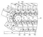
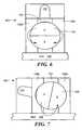
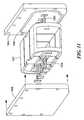
- FIG. 1is a schematic three-dimensional view of the bottom of an example of a hull robot
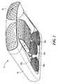
- FIG. 2is a schematic view showing the primary subsystems associated with the hull robot of FIG. 1 ;
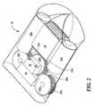
- FIG. 3is a block diagram showing several of the subsystems associated with a typical hull cleaning robot
- FIG. 4is a schematic three-dimensional partial front view showing several of the components associated with an example of a drive module
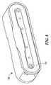
- FIG. 5is a schematic three-dimensional front view showing one example of a switchable permanent magnetic element associated with a drive module
- FIG. 6is a schematic cross-sectional side view showing the permanent magnet element of FIG. 5 in its shunted state
- FIG. 7is a schematic cross-sectional side view showing the permanent magnet element of FIG. 5 in its non-shunted state
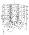
- FIG. 8is a schematic three-dimensional side view of an example of a tunnel body constraining the individual permanent magnet elements
- FIG. 9is a schematic three-dimensional side view showing an example of a portion of the mechanism which drives the tunnel body relative to the permanent magnet elements
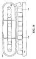
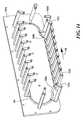
- FIG. 10is a schematic three-dimensional side view of a segmented tunnel body
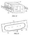
- FIG. 11is a schematic three-dimensional front view showing spaced side plate members flexibly supporting the segmented tunnel body shown in FIG. 10 ;
- FIG. 12is a schematic three-dimensional front view showing in more detail the flexure members of FIG. 11 ;
- FIG. 13is a schematic three-dimensional front view of the inside of one of the panels of FIG. 11 ;
- FIG. 14is a schematic three-dimensional front view of the panels shown in FIG. 13 depicting how a feature in the panel acts as the switch actuator;
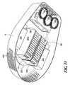
- FIG. 15is a schematic three-dimensional bottom view showing an example including a plurality of drive modules in place on a hull robot.
- FIGS. 1-2show one example of hull robot 10 with robot body 16 supporting combined turbine/generator units 32 a and 32 b .
- the turbinesare responsive to fluid moving past the vessel hull when the vessel is underway, e.g., the turbine intakes are behind screen 30 and are responsive to fluid moving past the vessel hull.
- the turbinesdrive the generators which in turn charge battery pack 38 .
- Electronic control module 40is powered by battery pack 38 as are the motors and other power devices on-board robot 10 .
- one motordrives, for example, gear 42 b which in turn drives gears 42 a and 42 c . In this way, cleaning brushes 36 a - 36 c are operated.
- Another motoris typically associated with drive module 18 which both holds the robot on the hull and maneuvers the robot about the vessel hull.
- the motor system for drive module 18may vary in design.
- the turbinescould directly drive module 18 (and/or brushes 36 a - 36 c ).
- brushes 36 a - 36 ccould be driven in different ways.
- FIG. 3illustrates an example including turbine subsystem 32 (including one or more devices actuatable by fluid flowing past the hull) and generator 70 which recharges power source 40 .
- One or more motorssuch as motors 72 a and 72 b are powered by power source 40 .
- Motor 72 adrives drive module 18 via drive train 74 a .
- the direction of travel of the robotcan be reversed via electronic control subsystem 41 which is configured to reverse the direction of motor 72 a based on inputs, for example, from navigation subsystem 78 and/or communication subsystem 80 .
- Electronic controller 41is also powered by power source 40 .
- motor 72 bdrives cleaning subsystem 82 (e.g., one or more brushes as described above) via drive train 74 b .
- Motor 72 bis also energized by power source 40 .
- the one or more motorsmay operate on the basis of a power source other than electricity. Motors are known, for example, that are fluid driven. The turbine subsystem then, may pump fluid under pressure to the motors. If the cleaning subsystem is passive, e.g., a pad and/or a squeegee, motor 72 b and drive train 74 b would not be required.
- the drive shafts of the turbinesare mechanically linked to the cleaning brushes and/or drive module.
- the design of the motive subsystem for the drive modulemay vary.
- FIG. 4schematically depicts certain components of a version of a preferred drive module.
- Switch assembly 102switches element 100 between a shunted and a non-shunted state.
- Actuator 104actuates switch 102 typically between a shunted state when element 100 is not adjacent the vessel hull and a non-shunted state when element 100 is adjacent the vessel hull.
- Tunnel body 106is configured to constrain the movement of element 100 which typically includes some type of carriage 108 .
- FIG. 5shows a design where permanent magnet element 100 includes diametrically polarized cylindrical magnet 120 rotatably disposed in a bore of housing 122 .
- Housing 122includes non-magnetic material 124 (e.g., aluminum, plastic, or the like) sandwiched between ferromagnetic material 126 a and 126 b (e.g., steel).
- Switch 102is attached to cylindrical magnet 120 and rotates it as shown in FIG. 6-7 .
- magnet 120is shunted since the magnetic field flows from the north pole, outwardly through ferromagnetic material 126 a and 126 b , and to the south pole. The attraction of magnet 120 to vessel hull 130 is thus minimized.
- Activating switch 102rotates magnet 120 as shown in FIG. 7 so each pole is proximate ferromagnetic material 126 a or 126 b .
- the south poleis in contact with ferromagnetic material 126 a and the north pole is in contact with ferromagnetic material 126 b .
- the magnetic fieldflows from the north pole of the magnet into body 126 b , to the ship's hull 130 , to body 126 a , and then back to the south pole of the magnet. In this non-shunted state, the attraction of magnet 120 to hull 130 is maximized.
- switch 102is activated to shunt magnet 120 as permanent magnet element 100 reaches the end of its travel on the hull and switch 102 is again activated to actuate magnet 120 as permanent magnet element 100 again comes into contact with the hull.
- power usageis minimized and yet there is still a very strong tractive force provided to keep the robot on the hull. Power usage is minimized because power is not wasted in removing the individual permanent magnet elements from the hull. Also, damage to the hull is minimized since the permanent magnet elements are not switched to their non-shorted states until they are actually in contact with the hull.
- Each permanent magnet elementmay include a protective covering to also reduce damage to the vessel hull. The intent is to control the holding force exerted by the magnets but at the same time use permanent magnets which consume no power unlike electromagnets.
- FIG. 5also shows carriage 108 ′ with spaced rotating bearings 140 a and 140 b and connectors 142 a - 142 d .
- Bearings 140 a and 140 bride in side tracks in tunnel body 106 ′, FIG. 8 .
- oval shaped side track 152is shown.
- FIG. 9shows how tunnel body 106 ′ supports a drive train such as spaced sprocket wheels including wheel 160 (which may be driven by motor 72 a and drive train 74 a , FIG. 3 ).
- Chain 162extends around the spaced sprocket wheels.
- Bearing 140 b of carriage 108 ′ of permanent magnet element 100 ais constrained in track 152 of tunnel body 106 ′ and connectors 142 c and 142 d extend into chain 162 .
- tunnel body 106 ′is fixed to robot body 10 , FIGS. 1-2 and since permanent magnet elements 100 b - 100 e in their non-shunted states are strongly attracted to vessel hull 130 , chain 162 actually drives tunnel body 106 ′ forward (and rearward) and thus the robot body is driven with respect to the vessel hull via the rotation of chain 162 and about sprocket 160 .
- FIG. 9also shows that permanent magnet element 100 a is shunted via the position of switch 102 .
- Permanent magnet element 100 xis either an element first coming into position to be attracted to the hull 130 or it is leaving hull 130 depending on the direction of robot travel. If permanent magnet element 100 x is just coming into position to be attracted to hull 130 , it is switched from the shunted position shown to its non-shunted position once permanent magnet element 100 x occupies the position of permanent magnet element 100 b . If permanent magnet element 100 x is just leaving hull 130 , or is about to leave the hull, it is switched into a shunted state just after it occupies the position of permanent magnet element 100 b.
- FIG. 10shows a segmented design for tunnel body 106 ′′ to allow for articulation of the tunnel body and track system to maximize the contact area for each permanent magnet element in the presence of non-uniformities 170 a and 170 b on hull 130 .
- spaced panels 180 a and 180 bsupport tunnel body 106 ′′ via flexures 182 a , 182 b , and the like, FIGS. 11-12 .
- Side panels 180 a and 180 bare affixed to the robot body or to a turret rotatably attached to the robot body.
- FIG. 11also shows an actuation feature such as closed loop groove 184 a on the inside of panel 180 b .
- these grooves in the side panelsfunction to actuate the switches of the permanent magnet elements.
- FIG. 11also shows an actuation feature such as closed loop groove 184 a on the inside of panel 180 b .
- these grooves in the side panelsfunction to actuate the switches of the permanent magnet elements.
- At groove ends 186 a and 186 bthere is a jog. If the direction of travel of the hull robot is as shown by arrow 188 and the vessel
- FIG. 14shows more complete switching assemblies 102 a - 102 d and depicts how switch 102 a is in its shunted position but switch 102 b , via groove jog 186 a , has been actuated to its non-shunted position. Similarly, jog 186 b turns switch 102 c to the shunted position for the remainder of its travel about the front and top of panel 180 a corresponding to the front and top of tunnel body 106 ′, FIG. 9 .
- FIG. 15shows two complete drive modules 18 a and 18 b mounted to turret 200 which may be rotatable with respect to the robot body.
- turret 200can be rotated to keep the intakes of turbine/generator assemblies 32 a and 32 b aligned with the direction of water flowing past the vessel hull irrespective of the direction of travel of the robot about the vessel hull. See U.S. patent application Ser. No. 12/583,346, filed Aug. 19, 2009.
- the tunnel bodyperforms two functions: it constrains the movement of the permanent magnet elements and also serves to house the drive mechanism (e.g., a chain about two sprockets) connected to the carriages of the permanent magnet elements.
- This designalso provides structural support against slack in the drive assembly.
- the side platesalso serve two functions: they flexibly support the tunnel body and they include means for actuating the switches of the permanent magnet elements.
- the magnetic elementsare switched between their minimum tractive state and their maximum tractive state irrespective of the direction of travel of the robot.
Landscapes
- Engineering & Computer Science (AREA)
- Chemical & Material Sciences (AREA)
- Combustion & Propulsion (AREA)
- Mechanical Engineering (AREA)
- Ocean & Marine Engineering (AREA)
- Electromagnetism (AREA)
- Physics & Mathematics (AREA)
- Power Engineering (AREA)
- Transportation (AREA)
- Manipulator (AREA)
- Connection Of Motors, Electrical Generators, Mechanical Devices, And The Like (AREA)
- Control Of Position, Course, Altitude, Or Attitude Of Moving Bodies (AREA)
- Toys (AREA)
- Electric Vacuum Cleaner (AREA)
Abstract
Description
This application is a continuation application of U.S. patent application Ser. No. 12/587,949, filed Oct. 14, 2009, which is incorporated by reference herein in its entirety.
The subject invention relates to a hull robot typically configured to clean and/or inspect the hull of a vessel and, in particular, to a drive module for such a hull robot.
Robots have been proposed to clean and inspect vessels and underwater structures. Such robots typically include a drive subsystem for maneuvering the robot about the vessel or structure hull. Some drive subsystems include magnetic wheels or rollers. See U.S. Pat. Nos. 5,628,271; 3,088,429; and 2,104,062. The magnetic wheels of the '271 patent are stated to provide a holding power in excess of 2,000 pounds. The motor and drive train driving these wheels provides sufficient torque to overcome the strong magnetic tractive force. For example, the motor is stated to be a 24 volt DC motor providing 400 RPM.
Other drive subsystems include rollers and some means of adhering the robot to the hull via suction. See U.S. Pat. Nos. 4,809,383; 6,102,145; and 6,053,267. Some use rollers or wheels and a magnet spaced from the hull. See U.S. Pat. Nos. 6,564,815; 3,922,991; and 3,777,834. U.S. Pat. No. 4,697,537 discloses an impeller driven by a motor urging the robot against the hull.
Magnetic tracks and tracks with magnetic shoes have also been proposed. See U.S. Pat. Nos. 3,960,229; 2,132,661; 4,690,092; and 4,890,567 all disclosing electromagnets which may be selectively energized to control the drag force exerted by the magnets. U.S. Pat. No. 5,285,601, incorporated herein by this reference, discloses a blast cleaning device with two treads each including permanent magnets which continuously apply a tractive force.
Some proposed hull cleaning robots are powered via a tether or cable connected between the robot and a power source on board the vessel. It may be advantageous, however, for a hull robot to operate more autonomously in which case the power source for the drive subsystem, cleaning brushes, and the like would be on-board the robot typically in the form of a battery or battery pack. Drive subsystems including electromagnetics are not favored because electromagnets may require too much power to operate. High voltage powerful motors for the drive subsystem are also not favored when battery power is used. At the same time, if permanent magnets are used and they provide a fairly strong tractive force, it can be difficult to engineer a suitable drive subsystem.
Co-pending U.S. patent application Ser. No. 12/313,643 filed Nov. 21, 2008 by the assignee hereof proposes a robot with a battery pack charged via a turbine/generator subsystem driven by water flowing past the hull when the vessel is underway. In this manner, the hull robot can continuously clean and/or inspect the vessel hull. In such a hull robot, a permanent magnet type drive track is desired. But, as noted above, since the drive subsystem is battery powered, a mechanism to control the tractive force supplied by the permanent magnets is needed.
One embodiment features, in one aspect, a hull cleaning and/or inspection robot which is powered via fluid moving past the hull while the vessel is underway. A preferred drive module may include a plurality of permanent magnet elements constrained by a tunnel body and switchable between a shunted state and a non-shunted state. In this way, the magnets are shunted as they reach the end of their travel along the tunnel body and remain shunted until they again engage the hull to conserve battery power. In their non-shunted state, the magnets provide a sufficient tractive force to keep the hull robot on the hull of the vessel. In other embodiments, the drive module hereof may be used in conjunction with systems other than a hull cleaning and/or inspection robot.
An example of a hull robot includes a robot body, at least one drive module for maneuvering the robot about the hull, an on-board power source, and a motive subsystem for the drive module powered by the on-board power source. A plurality of permanent magnet elements are associated with the drive module and each are switchable between a non-shunted state when adjacent a hull and a shunted state when not adjacent the hull.
The motive subsystem may include at least one turbine powered by fluid moving past the hull, a generator driven by the turbine for charging the on-board power source, and a motor powered by the on-board power source driving the drive module. A typical on-board power source includes at least one battery.
In one version, each magnet element includes a diametrically polarized cylindrical magnet rotatably disposed in a housing. The preferred housing includes non-magnetic material sandwiched between ferromagnetic material. Each magnet element may further include a switch attached to the cylindrical magnet for rotating the cylindrical magnet in the housing between the shunted state and the non-shunted state.
In one example, the drive module may also include a tunnel body and each magnet element may include a carriage which maneuvers with respect to the tunnel body. The tunnel body may include opposing side tracks and the carriage then includes spaced bearings riding in the side tracks of the tunnel body. The typical tunnel body may support a drive train and each carriage is connected to the drive train. In one example, the drive train may include a chain about spaced sprockets engaging the chain. Each carriage typically includes at least one connector extending into the chain.
There may also be spaced panels supporting the tunnel body. A plurality of flexures typically may extend between each supporting panel and the tunnel body. In one example, the tunnel body is segmented and there is at least one flexure per segment. One or both panels may include a switching feature such as a closed loop groove therein. The magnet switch assemblies ride in the groove and the groove is configured to activate switch assemblies to rotate the magnets at opposing ends of the closed loop. Each magnet element may also include a protective covering.
Also featured is a drive module including a plurality of magnet elements each having a housing with non-magnetic material sandwiched between ferromagnetic material and a bore extending into the housing, a magnet rotatably disposed in the bore, and a switch assembly for rotating the magnet. A carriage for each magnet includes at least one bearing and a connector. A tunnel body includes at least one track for the bearings of the carriages. A drive train for the tunnel body is attached to the connectors of the carriages. At least one panel supports the tunnel body. The panel typically includes means for actuating the switch assemblies such as a feature in the panel actuating the switch assemblies. The feature is configured to rotate the magnet at opposing ends of the tunnel.
One drive module features a plurality of permanent magnet elements each switchable between a non-shunted state and a shunted state, a switch assembly for each magnet element rotating each permanent magnet element to change the state thereof, a tunnel body constraining the permanent magnet elements, and a drive train for driving the tunnel body with respect to the permanent magnet elements. In one example, the means drive train includes spaced wheels rotatably supported by the tunnel assembly and a flexible member about the wheels connected to the permanent magnet elements.
Thus, the subject invention in some embodiments, need not achieve all the above objectives and the claims hereof should not be limited to structures or methods capable of achieving these objectives.
Other objects, features and advantages will occur to those skilled in the art from the following description of a preferred embodiment and the accompanying drawings, in which:
Aside from the preferred embodiment or embodiments disclosed below, this invention is capable of other embodiments and of being practiced or being carried out in various ways. Thus, it is to be understood that the invention is not limited in its application to the details of construction and the arrangements of components set forth in the following description or illustrated in the drawings. If only one embodiment is described herein, the claims hereof are not to be limited to that embodiment. Moreover, the claims hereof are not to be read restrictively unless there is clear and convincing evidence manifesting a certain exclusion, restriction, or disclaimer.
Typically,switch 102 is activated to shuntmagnet 120 aspermanent magnet element 100 reaches the end of its travel on the hull and switch102 is again activated to actuatemagnet 120 aspermanent magnet element 100 again comes into contact with the hull. In this way, power usage is minimized and yet there is still a very strong tractive force provided to keep the robot on the hull. Power usage is minimized because power is not wasted in removing the individual permanent magnet elements from the hull. Also, damage to the hull is minimized since the permanent magnet elements are not switched to their non-shorted states until they are actually in contact with the hull. Each permanent magnet element may include a protective covering to also reduce damage to the vessel hull. The intent is to control the holding force exerted by the magnets but at the same time use permanent magnets which consume no power unlike electromagnets.
Sincetunnel body 106′ is fixed torobot body 10,FIGS. 1-2 and sincepermanent magnet elements 100b-100ein their non-shunted states are strongly attracted tovessel hull 130,chain 162 actually drivestunnel body 106′ forward (and rearward) and thus the robot body is driven with respect to the vessel hull via the rotation ofchain 162 and aboutsprocket 160.
In one preferred design, the tunnel body performs two functions: it constrains the movement of the permanent magnet elements and also serves to house the drive mechanism (e.g., a chain about two sprockets) connected to the carriages of the permanent magnet elements. This design also provides structural support against slack in the drive assembly. The side plates also serve two functions: they flexibly support the tunnel body and they include means for actuating the switches of the permanent magnet elements. In the preferred design, the magnetic elements are switched between their minimum tractive state and their maximum tractive state irrespective of the direction of travel of the robot. These are not limitations of the subject invention, however, as other designs are possible.
Other features associated with the typical hull robot are disclosed in the patents cited in the Background section hereof and incorporated herein by this reference. Also, U.S. patent application Ser. No. 12/313,643 filed Nov. 21, 2008 by the assignee hereof discloses additional features which may be associated with a hull robot. The drive module disclosed herein, however, is not limited to use in connection with such a vessel hull robot. The drive module, for example, can be used on any ferromagnetic body including but not limited to vessel hulls, underwater structures, and the like. “Hull,” as used herein, then, broadly means a structure to be traversed.
Thus, although specific features of the invention are shown in some drawings and not in others, this is for convenience only as each feature may be combined with any or all of the other features in accordance with the invention. The words “including”, “comprising”, “having”, and “with” as used herein are to be interpreted broadly and comprehensively and are not limited to any physical interconnection. Moreover, any embodiments disclosed in the subject application are not to be taken as the only possible embodiments.
In addition, any amendment presented during the prosecution of the patent application for this patent is not a disclaimer of any claim element presented in the application as filed: those skilled in the art cannot reasonably be expected to draft a claim that would literally encompass all possible equivalents, many equivalents will be unforeseeable at the time of the amendment and are beyond a fair interpretation of what is to be surrendered (if anything), the rationale underlying the amendment may bear no more than a tangential relation to many equivalents, and/or there are many other reasons the applicant can not be expected to describe certain insubstantial substitutes for any claim element amended.
Other embodiments will occur to those skilled in the art and are within the following claims.
Claims (17)
1. A hull robot comprising:
a robot body;
at least one drive module for maneuvering the robot about a hull;
an on-board power source;
a motive subsystem for the drive module powered by the on-board power source; and
a plurality of permanent magnet elements associated with the drive module each switchable between a non-shunted state when adjacent the hull and a shunted state when not adjacent the hull.
2. The hull robot ofclaim 1 in which the motive subsystem includes at least one turbine powered by fluid moving past the hull, a generator driven by the turbine for charging the on-board power source, and a motor powered by the on-board power source driving the drive module.
3. The hull robot ofclaim 1 in which the on-board power source includes at least one battery.
4. The hull robot ofclaim 1 in which each magnet element includes a diametrically polarized cylindrical magnet rotatably disposed in a housing.
5. The hull robot ofclaim 4 in which the housing includes non-magnetic material sandwiched between ferromagnetic material.
6. The hull robot ofclaim 4 in which each magnet element further includes a switch attached to the cylindrical magnet for rotating the cylindrical magnet in the housing between the shunted state and the non-shunted state.
7. The hull robot ofclaim 4 in which the tunnel body supports a drive train.
8. The hull robot ofclaim 7 in which each carriage is connected to the drive train.
9. The hull robot ofclaim 7 in which the drive train includes a chain about spaced sprockets engaging the chain.
10. The hull robot ofclaim 9 in which each carriage includes at least one connector extending into the chain.
11. The hull robot ofclaim 1 in which the tunnel body includes opposing side tracks and the carriage includes spaced bearings riding in the side tracks of the tunnel body.
12. The hull robot ofclaim 1 further including spaced panels supporting the tunnel body.
13. The hull robot ofclaim 12 further including a plurality of flexures extending between each supporting panel and the tunnel body.
14. The hull robot ofclaim 12 in which at least one said panel includes a closed loop groove therein, the switch assembly rides in the groove, and the groove is configured to activate the switch assemblies to rotate the magnets at opposing ends of the closed loop.
15. The hull robot ofclaim 1 which the tunnel body is segmented and there is at least one flexure per segment.
16. The hull robot ofclaim 1 in which each magnet element includes a rotatable magnet and a switch assembly attached thereto.
17. The hull robot ofclaim 1 in which each magnet element includes a protective covering.
Priority Applications (1)
| Application Number | Priority Date | Filing Date | Title |
|---|---|---|---|
| US13/794,594US9233724B2 (en) | 2009-10-14 | 2013-03-11 | Hull robot drive system |
Applications Claiming Priority (2)
| Application Number | Priority Date | Filing Date | Title |
|---|---|---|---|
| US12/587,949US8393421B2 (en) | 2009-10-14 | 2009-10-14 | Hull robot drive system |
| US13/794,594US9233724B2 (en) | 2009-10-14 | 2013-03-11 | Hull robot drive system |
Related Parent Applications (1)
| Application Number | Title | Priority Date | Filing Date |
|---|---|---|---|
| US12/587,949ContinuationUS8393421B2 (en) | 2009-10-14 | 2009-10-14 | Hull robot drive system |
Publications (2)
| Publication Number | Publication Date |
|---|---|
| US20140090906A1 US20140090906A1 (en) | 2014-04-03 |
| US9233724B2true US9233724B2 (en) | 2016-01-12 |
Family
ID=43853804
Family Applications (2)
| Application Number | Title | Priority Date | Filing Date |
|---|---|---|---|
| US12/587,949Active2031-04-26US8393421B2 (en) | 2009-10-14 | 2009-10-14 | Hull robot drive system |
| US13/794,594ActiveUS9233724B2 (en) | 2009-10-14 | 2013-03-11 | Hull robot drive system |
Family Applications Before (1)
| Application Number | Title | Priority Date | Filing Date |
|---|---|---|---|
| US12/587,949Active2031-04-26US8393421B2 (en) | 2009-10-14 | 2009-10-14 | Hull robot drive system |
Country Status (7)
| Country | Link |
|---|---|
| US (2) | US8393421B2 (en) |
| EP (1) | EP2488700A4 (en) |
| JP (1) | JP5638615B2 (en) |
| CN (1) | CN102575443B (en) |
| AU (1) | AU2010307302B2 (en) |
| TW (1) | TWI400179B (en) |
| WO (1) | WO2011046592A1 (en) |
Cited By (1)
| Publication number | Priority date | Publication date | Assignee | Title |
|---|---|---|---|---|
| US12365405B2 (en) | 2022-04-04 | 2025-07-22 | Saudi Arabian Oil Company | Dynamically magnetized chassis for crawling robotic vehicles |
Families Citing this family (30)
| Publication number | Priority date | Publication date | Assignee | Title |
|---|---|---|---|---|
| US9440717B2 (en)* | 2008-11-21 | 2016-09-13 | Raytheon Company | Hull robot |
| US9254898B2 (en)* | 2008-11-21 | 2016-02-09 | Raytheon Company | Hull robot with rotatable turret |
| US8393421B2 (en) | 2009-10-14 | 2013-03-12 | Raytheon Company | Hull robot drive system |
| US10315715B2 (en)* | 2010-11-08 | 2019-06-11 | James Beard | Mobile, climbing endless track robotic system to perform remote inspections on structures |
| US9180934B2 (en) | 2012-09-14 | 2015-11-10 | Raytheon Company | Hull cleaning robot |
| WO2014062317A2 (en)* | 2012-09-14 | 2014-04-24 | Raytheon Company | Autonomous hull inspection |
| GB201219764D0 (en) | 2012-11-02 | 2012-12-19 | Epsco Ltd | Method and apparatus for inspection of cooling towers |
| US9096283B2 (en)* | 2012-11-26 | 2015-08-04 | Foster-Miller, Inc. | Magnet robot crawler |
| EP2743173A1 (en)* | 2012-12-11 | 2014-06-18 | C-leanship Aps | A submergible cleaning system |
| CN103287554A (en)* | 2013-06-28 | 2013-09-11 | 张家港同宇智能机电科技有限公司 | Underwater ship cleaning brush |
| US9579927B2 (en) | 2013-11-30 | 2017-02-28 | Saudi Arabian Oil Company | Magnetic omni-wheel |
| US9540060B2 (en) | 2014-03-21 | 2017-01-10 | Qualcomm Incorporated | Omni-directional treads |
| KR101472290B1 (en)* | 2014-05-15 | 2014-12-12 | 김유식 | Multifunctional ship bottom apparatus |
| KR101472288B1 (en)* | 2014-05-15 | 2014-12-12 | 김유식 | Multifunctional ship bottom apparatus |
| US9533724B2 (en)* | 2015-02-17 | 2017-01-03 | The Boeing Company | Electro-permanent magnetic attachment of a vehicle to an object |
| US9616711B1 (en) | 2015-07-03 | 2017-04-11 | Jon Bills | Apparatus, system, and method for achieving magnetically harnessed locomotion of wheeled machines |
| US9840313B2 (en) | 2015-09-22 | 2017-12-12 | Sanuwave, Inc. | Cleaning and grooming water submerged structures using acoustic pressure shock waves |
| CN105774933B (en)* | 2016-03-22 | 2018-01-26 | 京东方科技集团股份有限公司 | Mobile platforms and how they work |
| EP4509396A3 (en)* | 2016-08-23 | 2025-06-25 | Cliin Robotics ApS | Hull and cargo hold cleaning apparatus and method |
| CN106516039B (en)* | 2016-11-16 | 2018-04-03 | 南通市海鸥救生防护用品有限公司 | Hull cleans monitoring underwater robot frame with water |
| US11577794B2 (en) | 2017-11-22 | 2023-02-14 | Sector Industries, Inc. | Apparatus and related method for coating an irregular surface |
| US10277163B1 (en)* | 2018-07-11 | 2019-04-30 | Evermore United S.A. | Magnetic parking for robotic cleaner on a solar panel |
| CN110112604A (en)* | 2019-04-26 | 2019-08-09 | 广州市旋通节能科技有限公司 | A kind of sub- ship of battery connects electric protective device |
| CN111361702A (en)* | 2020-03-18 | 2020-07-03 | 上海遨拓深水装备技术开发有限公司 | Ship bottom cleaning submersible system based on cavitation jet technology and use method thereof |
| CN112092997B (en)* | 2020-09-25 | 2021-10-08 | 大连海事大学 | Cleaning device of underwater ship body cleaning robot and working method thereof |
| KR102402001B1 (en)* | 2021-01-19 | 2022-05-26 | 한국과학기술원 | autonomous hull cleaning robot operable without requiring tether and human intervention |
| CN112985659B (en)* | 2021-02-22 | 2022-04-12 | 江苏徐工工程机械研究院有限公司 | Heavy-duty, high-power, high-torque chassis dynamometer under multi-environment system |
| CN113941918B (en)* | 2021-09-24 | 2023-08-29 | 北京石油化工学院 | Underwater polishing and dedusting robot |
| CN115195960A (en)* | 2022-06-21 | 2022-10-18 | 西北工业大学 | An automatic robot for cleaning attachments on the hull surface |
| KR20240175255A (en)* | 2023-06-12 | 2024-12-19 | 장상준 | exterior wall of ship cleaning device |
Citations (153)
| Publication number | Priority date | Publication date | Assignee | Title |
|---|---|---|---|---|
| US2104062A (en) | 1935-10-28 | 1938-01-04 | John C Temple | Surfacing machine |
| US2132661A (en) | 1935-11-29 | 1938-10-11 | John C Temple | Surfacing machine |
| US2386650A (en) | 1943-03-11 | 1945-10-09 | Leroy V Bell | Mother ship |
| US3058783A (en) | 1961-03-22 | 1962-10-16 | U S Naval Construction Battali | Accessory traction units |
| US3088429A (en) | 1961-06-28 | 1963-05-07 | Johannessen Harry De Fi Brandt | Cleaning devices for removing marine growth from ships' hulls |
| FR1352056A (en) | 1963-03-27 | 1964-02-07 | Inst Schiffbau | Rolling support with magnetic adhesion for use of devices on steel walls |
| US3285676A (en) | 1964-10-28 | 1966-11-15 | Polaris Inc | Rubber track |
| US3439937A (en) | 1965-09-30 | 1969-04-22 | Secr Defence Brit | Articulated vehicles |
| US3554300A (en) | 1969-05-28 | 1971-01-12 | Edgar N Rosenberg | Deep submergence tunneling device |
| US3638600A (en) | 1969-08-21 | 1972-02-01 | Henry J Modrey | Apparatus for treating ferrous surfaces |
| US3682265A (en) | 1969-05-16 | 1972-08-08 | Hitachi Metals Ltd | Magnet vehicle |
| JPS4814096Y1 (en) | 1969-08-01 | 1973-04-18 | ||
| US3750129A (en) | 1970-09-07 | 1973-07-31 | Tadashi Wakabayoshi Kowa | Conveyor belt apparatus |
| JPS491434Y1 (en) | 1969-08-09 | 1974-01-14 | ||
| JPS5012797Y1 (en) | 1970-12-19 | 1975-04-19 | ||
| JPS5081487U (en) | 1973-11-26 | 1975-07-14 | ||
| US3906572A (en) | 1965-03-04 | 1975-09-23 | Exxon Research Engineering Co | Apparatus for maneuvering on a submerged surface |
| US3922991A (en) | 1973-06-25 | 1975-12-02 | John W Woods | Apparatus for cleaning metallic surfaces |
| US3934664A (en) | 1973-02-01 | 1976-01-27 | Pohjola Jorma | Steering mechanism for track vehicles |
| US3946692A (en) | 1973-12-28 | 1976-03-30 | Phoceenne Sous Marine - Psm Les Hommes Grenouilies Du Port De Marseille | Device for cleaning ship's hulls and other immersed surfaces |
| US3960229A (en) | 1975-03-31 | 1976-06-01 | Cheng Shio | Electromagnetic vehicle |
| US3984944A (en) | 1974-06-21 | 1976-10-12 | Wolfgang Maasberg | Device for cleaning ship's sides, tank walls, and similar surfaces |
| US4046429A (en) | 1973-02-01 | 1977-09-06 | Pohjola Jorma | Steering mechanism for endless track vehicles |
| US4079694A (en) | 1975-12-01 | 1978-03-21 | Commissariat A L'energie Atomique | Apparatus for applying a coating to a submerged surface |
| US4119356A (en) | 1975-02-10 | 1978-10-10 | Pohjola Jorma | Vehicle and endless track structure therefor |
| US4135492A (en) | 1975-11-07 | 1979-01-23 | Volkswagenwerk Aktiengesellschaft | Manifold arrangement |
| US4135592A (en) | 1976-06-18 | 1979-01-23 | Trelleborgs Gummifabriks Aktiebolag | Four-wheel-drive articulated frame steering vehicle |
| US4202453A (en) | 1978-01-05 | 1980-05-13 | Timberline, Inc. | Articulated mine service vehicle |
| GB2038721A (en) | 1978-12-01 | 1980-07-30 | Bingham V P | Apparatus for cleaning ship's hulls |
| US4251791A (en) | 1978-12-08 | 1981-02-17 | Kanetsu Kogyo Kabushiki Kaisha | Magnetic base |
| JPS5812075B2 (en) | 1974-06-13 | 1983-03-05 | 株式会社クボタ | Scum High Shiyutsu Souchi |
| JPS5814096Y2 (en) | 1977-10-27 | 1983-03-19 | ダイハツ工業株式会社 | Lining panels for automobile doors |
| US4401048A (en) | 1982-03-17 | 1983-08-30 | Rogers Robert C | Portable boat hull scrubber |
| US4444146A (en) | 1982-01-13 | 1984-04-24 | Honeywell Inc. | Ultrasonic subsurface cleaning |
| GB2103162B (en) | 1981-07-17 | 1985-03-06 | Mitsui Shipbuilding Eng | Apparatus moving on wall |
| JPS6013117Y2 (en) | 1980-10-30 | 1985-04-26 | 富士通株式会社 | magnetic storage device |
| JPS60131174A (en) | 1983-12-21 | 1985-07-12 | 株式会社日立製作所 | wall walking machine |
| US4574722A (en) | 1982-10-06 | 1986-03-11 | Mitsui Engineering & Shipbuilding Co., Ltd. | Underwater cleaning apparatus |
| GB2165330A (en) | 1984-10-04 | 1986-04-09 | Remote Marine Systems Ltd | Ultrasonic cleansing |
| JPS6213099Y2 (en) | 1976-04-16 | 1987-04-04 | ||
| US4674949A (en) | 1982-01-11 | 1987-06-23 | International Robotic Engineering, Inc. | Robot with climbing feet |
| US4690092A (en) | 1986-06-05 | 1987-09-01 | Milton Rabuse | Aquatic scrubbing device |
| US4697536A (en) | 1984-02-27 | 1987-10-06 | West Tsusho Co., Ltd. | Underwater cleaning apparatus |
| US4697537A (en) | 1986-04-28 | 1987-10-06 | Smith Thomas C | Retractable line storage device |
| DE3611750A1 (en) | 1986-04-08 | 1987-10-22 | Braun Jean | Devices to make use of kinetic primary energy |
| US4734954A (en) | 1987-02-24 | 1988-04-05 | Paul Greskovics | Pool scrubber device |
| US4736826A (en) | 1985-04-22 | 1988-04-12 | Remote Technology Corporation | Remotely controlled and/or powered mobile robot with cable management arrangement |
| US4788498A (en) | 1986-01-28 | 1988-11-29 | Macome Corporation | Magnetic detector for an unmanned vehicle control system |
| US4789037A (en) | 1986-06-03 | 1988-12-06 | Remotely Operated Vehicles Limited | Self-propelled vehicle |
| US4809383A (en) | 1985-02-25 | 1989-03-07 | Uragami Fukashi | Device capable of adhering to a wall surface by suction and treating it |
| US4841894A (en) | 1988-03-02 | 1989-06-27 | Nellessen Jr Peter | Hull cleaner |
| US4890567A (en) | 1987-12-01 | 1990-01-02 | Caduff Edward A | Robotic ultrasonic cleaning and spraying device for ships' hulls |
| US4926775A (en) | 1986-08-21 | 1990-05-22 | Andorsen John P | Device for cleaning surfaces, particularly in water |
| US5048445A (en) | 1989-09-08 | 1991-09-17 | Cavi-Tech, Inc. | Fluid jet system and method for underwater maintenance of ship performance |
| JPH042592Y2 (en) | 1987-05-19 | 1992-01-29 | ||
| US5174222A (en) | 1991-11-04 | 1992-12-29 | Rogers Mark C | Apparatus for cleaning of ship hulls |
| JPH0519086B2 (en) | 1983-07-11 | 1993-03-15 | Oobaru Kk | |
| US5203646A (en) | 1992-02-06 | 1993-04-20 | Cornell Research Foundation, Inc. | Cable crawling underwater inspection and cleaning robot |
| US5249631A (en) | 1989-05-24 | 1993-10-05 | Bran Ferren | Water powered mobile robot |
| US5253724A (en) | 1991-10-25 | 1993-10-19 | Prior Ronald E | Power wheelchair with transmission using multiple motors per drive wheel |
| US5253605A (en) | 1992-12-21 | 1993-10-19 | Applied Remote Technology, Inc. | Method and apparatus for deploying and recovering water borne vehicles |
| US5285601A (en) | 1991-12-31 | 1994-02-15 | The Wheelabrator Corporation | Magnetic track self-propelled blast cleaning machine |
| US5337434A (en) | 1993-04-12 | 1994-08-16 | Aqua Products, Inc. | Directional control means for robotic swimming pool cleaners |
| US5366038A (en) | 1992-08-25 | 1994-11-22 | Nishiguchi Hidetsugu | Robot traveling on wall face |
| JPH0699888B2 (en) | 1989-07-14 | 1994-12-07 | 東亞ペイント株式会社 | Method of forming road markings with good visibility in rainy or night time |
| US5378994A (en) | 1990-04-24 | 1995-01-03 | Novak; James L. | Non-contact capacitance based image sensing method and system |
| US5435405A (en) | 1993-05-14 | 1995-07-25 | Carnegie Mellon University | Reconfigurable mobile vehicle with magnetic tracks |
| US5569371A (en) | 1994-04-22 | 1996-10-29 | Maytronics Ltd. | System for underwater navigation and control of mobile swimming pool filter |
| JPH08310384A (en) | 1995-05-16 | 1996-11-26 | Jishaku Yuso Syst Kaihatsu Kk | Magnet type chain belt |
| US5628271A (en) | 1995-03-22 | 1997-05-13 | Amclean, Inc. | Apparatus and method for removing coatings from the hulls of vessels using ultra-high pressure water |
| JPH1016884A (en) | 1996-07-04 | 1998-01-20 | Penta Ocean Constr Co Ltd | Diving equipment for underwater floating structures |
| US5831432A (en) | 1995-11-09 | 1998-11-03 | Research Development Corporation Of Japan | Differential magneto-impedance magnetic field sensor |
| US5849099A (en) | 1995-01-18 | 1998-12-15 | Mcguire; Dennis | Method for removing coatings from the hulls of vessels using ultra-high pressure water |
| US5852984A (en) | 1996-01-31 | 1998-12-29 | Ishikawajimi-Harima Heavy Industries Co., Ltd. | Underwater vehicle and method of positioning same |
| US5884642A (en) | 1997-08-07 | 1999-03-23 | Broadbent Spray Rentals | Remotely controlled pressurized liquid dispensing mobile unit |
| US5894901A (en) | 1995-12-12 | 1999-04-20 | Babcock-Hitachi Kabushiki Kaisha | Endless track magnetic traveling device |
| US5947051A (en) | 1997-06-04 | 1999-09-07 | Geiger; Michael B. | Underwater self-propelled surface adhering robotically operated vehicle |
| US6000484A (en) | 1996-09-25 | 1999-12-14 | Aqua Dynamics, Inc. | Articulating wheeled permanent magnet chassis with high pressure sprayer |
| US6053267A (en) | 1998-06-25 | 2000-04-25 | Technical Mechanical Resource Associates, Inc. | Coating removal vehicle with inflatable suction ring |
| US6064708A (en) | 1997-07-17 | 2000-05-16 | Kabushiki Kaisha Toshiba | Underwater inspection/repair apparatus |
| US6102145A (en) | 1998-06-25 | 2000-08-15 | Technical Mechanical Resource Associates, Inc. | Coating removal vehicle with resilient suction ring |
| US6125955A (en) | 1999-03-11 | 2000-10-03 | Aqua Dynamics, Inc. | Magnetic wheel |
| CN2405719Y (en) | 2000-01-26 | 2000-11-15 | 阎炳义 | Track-type permanent-magnet clambing mechanism |
| US6209473B1 (en) | 1997-06-23 | 2001-04-03 | Umc International Plc | Treatment of an underwater surface |
| US6276478B1 (en) | 2000-02-16 | 2001-08-21 | Kathleen Garrubba Hopkins | Adherent robot |
| US6317387B1 (en) | 1997-11-20 | 2001-11-13 | D'amaddio Eugene R. | Method and apparatus for inspecting a submerged structure |
| WO2002074611A3 (en) | 2001-03-16 | 2002-12-27 | Ultrastrip Systems Inc | Air gap magnetic mobile robot |
| US20030000445A1 (en) | 1995-03-22 | 2003-01-02 | Mcguire Dennis | Apparatus and method for removingcpatomgs from the hulls of vessels using ultra-high pressure water |
| JP2003025265A (en) | 2001-07-11 | 2003-01-29 | Mitsubishi Heavy Ind Ltd | Underwater robot operation support simulator |
| CN2552648Y (en) | 2002-07-12 | 2003-05-28 | 阎炳义 | Crawler-type permanent magnet creeping mechanism |
| WO2003087501A1 (en) | 2002-04-09 | 2003-10-23 | Haski Robert R | Dual direction water surface skimmer and pool side docking device. |
| US6698375B2 (en) | 1999-03-01 | 2004-03-02 | Barry E. Delfosse | Small waterplane area multihull (SWAMH) vessel |
| US6698376B2 (en) | 2001-04-13 | 2004-03-02 | Societe Eca | Device for launching and recovering an underwater vehicle and implementation method |
| US20040089216A1 (en) | 2001-05-30 | 2004-05-13 | Van Rompay Boudewijn Gabriel | Device for removing the growth on a ship's hull |
| US20040133999A1 (en) | 2003-01-13 | 2004-07-15 | Walton Charles A. | Underwater cleaning and scrubbing apparatus |
| US6792335B2 (en) | 2001-05-23 | 2004-09-14 | Carnegie Mellon University | Robotic apparatuses, systems and methods |
| US20040250934A1 (en) | 2003-06-11 | 2004-12-16 | Randy Hamdan | Tires with magnetic strips |
| US20050027412A1 (en) | 2003-05-19 | 2005-02-03 | Hobson Brett W. | Amphibious robot devices and related methods |
| WO2005014387A1 (en) | 2003-08-07 | 2005-02-17 | Company Ex As | Apparatus for cleaning the hull exterior of a seagoing vessel |
| FR2861457A1 (en) | 2003-10-28 | 2005-04-29 | Marc Serge Brussieux | Device for non-destructive testing of structures, particularly ship hulls, using number of non-destructive testing detectors and mobile robot to carry them |
| US6886651B1 (en) | 2002-01-07 | 2005-05-03 | Massachusetts Institute Of Technology | Material transportation system |
| US20050156562A1 (en) | 2004-01-21 | 2005-07-21 | Irobot Corporation | Autonomous robot auto-docking and energy management systems and methods |
| US20050199171A1 (en) | 2004-03-10 | 2005-09-15 | Ecklund William G. | Ship hull cleaning apparatus and method of use |
| US20050216125A1 (en) | 2004-03-15 | 2005-09-29 | University Of Vermont | Systems comprising a mechanically actuated magnetic on-off attachment device |
| JP2005335882A (en) | 2004-05-26 | 2005-12-08 | Kanto Auto Works Ltd | Conveyor rail cleaning device |
| US20060175439A1 (en) | 2005-02-08 | 2006-08-10 | Steur Gunnar V D | Voltage and turbine speed control apparatus for a rotary atomizer |
| US20060191457A1 (en) | 2003-07-03 | 2006-08-31 | Murphy Robert J | Marine payload handling craft and system |
| US20060249622A1 (en) | 2005-05-04 | 2006-11-09 | Lockheed Martin Corporation | Autonomous Environmental Control System and Method For Post-Capture and Pre-Launch Management of an Unmanned Air Vehicle |
| CN1864944A (en) | 2005-05-17 | 2006-11-22 | Lg电子株式会社 | Position-recognizing system for self-moving robot |
| US20070089916A1 (en) | 2003-11-14 | 2007-04-26 | Lundstroem Lennart | Electrically propulsed vehicle |
| EP1785552A2 (en) | 2005-11-15 | 2007-05-16 | Fabrizio Bernini | Automatic cleaner for swimming pools |
| US7286214B2 (en) | 2003-08-25 | 2007-10-23 | University Of South Florida | Method and program product for determining a radiance field in an optical environment |
| US7290496B2 (en) | 2005-10-12 | 2007-11-06 | Asfar Khaled R | Unmanned autonomous submarine |
| US7296530B1 (en) | 2005-12-12 | 2007-11-20 | United States Of America As Represented By The Secretary Of The Navy | Unmanned system for underwater object inspection, identification and/or neutralization |
| WO2007137234A2 (en) | 2006-05-19 | 2007-11-29 | Irobot Corporation | Removing debris from cleaning robots |
| US20070276552A1 (en) | 2006-02-24 | 2007-11-29 | Donald Rodocker | Underwater crawler vehicle having search and identification capabilities and methods of use |
| US20070284904A1 (en) | 2006-06-07 | 2007-12-13 | Evandro Carvalho | Transformable tail gate for truck bed |
| US20070284910A1 (en) | 2006-05-03 | 2007-12-13 | Magna Car Top Systems Gmbh | Movable vehicle roof assembly |
| US20070284940A1 (en) | 2006-06-09 | 2007-12-13 | Hiran Koolhiran | Track Shoe Assembly for Tracked Vehicle |
| US20080009984A1 (en) | 2006-07-07 | 2008-01-10 | Industrial Technology Research Institute | Path guidance method for autonomous mobile device |
| US7390560B2 (en) | 2004-04-02 | 2008-06-24 | Pel Associates | Smart coating systems |
| US20080202405A1 (en) | 2007-02-26 | 2008-08-28 | Physical Sciences, Inc. | Launch and Recovery Devices for Water Vehicles and Methods of Use |
| US20080281470A1 (en) | 2007-05-09 | 2008-11-13 | Irobot Corporation | Autonomous coverage robot sensing |
| US20080300821A1 (en) | 2007-01-20 | 2008-12-04 | Kcf Technologies, Inc. | Smart tether system for underwater navigation and cable shape measurement |
| US20080308324A1 (en) | 2007-06-14 | 2008-12-18 | Roland Moser | Drive unit for an inspection vehicle and also inspection vehicle with such a drive unit |
| US7496226B2 (en) | 2003-09-19 | 2009-02-24 | University Of Miami | Multi-camera inspection of underwater structures |
| US20090078484A1 (en) | 2006-03-13 | 2009-03-26 | Matswitch Technology Worldwide Pty Ltd | Magnetic wheel |
| US20090094765A1 (en) | 2006-03-14 | 2009-04-16 | Yanmar Co., Ltd. | Submersible cleaning robot |
| US7520356B2 (en) | 2006-04-07 | 2009-04-21 | Research Foundation Of The City University Of New York | Modular wall climbing robot with transition capability |
| US20090166102A1 (en) | 2007-12-20 | 2009-07-02 | Markus Waibel | Robotic locomotion method and mobile robot |
| US20090301203A1 (en) | 2005-04-28 | 2009-12-10 | Roboplanet | Tool, Sensor, and Device for a Wall Non-Distructive Control |
| US20100000723A1 (en) | 2006-02-23 | 2010-01-07 | Colin James Chambers | System, Method and Apparatus for Transferring Heat |
| US20100131098A1 (en) | 2008-11-21 | 2010-05-27 | Rooney Iii James H | Hull robot with rotatable turret |
| US20100126403A1 (en) | 2008-11-21 | 2010-05-27 | Rooney Iii James H | Hull Robot |
| US20100217436A1 (en) | 2009-02-24 | 2010-08-26 | Christopher Vernon Jones | Method and Device for Manipulating an Object |
| US20100219003A1 (en) | 2008-11-21 | 2010-09-02 | Rooney Iii James H | Hull robot steering system |
| US20100238050A1 (en) | 2007-06-15 | 2010-09-23 | Mark Rhodes | Wireless underwater hull inspection system |
| WO2010134022A1 (en) | 2009-05-18 | 2010-11-25 | Andrea Rizzo | Cleaner device for boat hulls |
| US7866421B2 (en) | 2008-01-28 | 2011-01-11 | Siemens Energy, Inc. | Automated remote carriage for tightening generator wedges |
| WO2011015786A1 (en) | 2009-08-05 | 2011-02-10 | Hulltimo | Automatic hull-cleaning robot |
| US20110050374A1 (en) | 2009-08-27 | 2011-03-03 | Edward Leroy Dvorak | Adhesion and braking system for a magnetic shipping container crawling apparatus |
| WO2011034558A1 (en) | 2009-09-18 | 2011-03-24 | Raytheon Company | Hull robot garage |
| US20110083599A1 (en) | 2009-10-14 | 2011-04-14 | Kornstein Howard R | Hull robot drive system |
| US20110208417A1 (en) | 2009-12-29 | 2011-08-25 | Research In Motion Limited | System and method of representing route information |
| US20110282536A1 (en) | 2010-05-17 | 2011-11-17 | Rooney Iii James H | Vessel hull robot navigation subsystem |
| US20120006352A1 (en) | 2009-11-23 | 2012-01-12 | Searobotics Corporation | Robotic submersible cleaning system |
| US8109383B1 (en) | 2010-08-05 | 2012-02-07 | Bunting Magnetics Co. | Magnetic assembly for loading and conveying ferrous metal articles |
| US8214081B2 (en) | 2006-09-29 | 2012-07-03 | Samsung Heavy Ind. Co., Ltd. | Multi-function robot for moving on wall using indoor global positioning system |
| WO2012104109A1 (en) | 2011-02-03 | 2012-08-09 | Raytheon Anschütz Gmbh | Device and method for navigating a movable device along a surface of a material structure |
| US20120215348A1 (en) | 2011-02-19 | 2012-08-23 | Richard Arthur Skrinde | Submersible robotically operable vehicle system for infrastructure maintenance and inspection |
| US20140076225A1 (en) | 2012-09-14 | 2014-03-20 | Raytheon Company | Autonomous Hull Inspection |
| US8723536B2 (en) | 2010-03-31 | 2014-05-13 | Hitachi High-Technologies Corporation | Inspection apparatus, substrate mounting device and inspection method |
| US8985250B1 (en) | 2010-12-14 | 2015-03-24 | Camoplast Solideal Inc. | Track drive mode management system and methods |
Family Cites Families (5)
| Publication number | Priority date | Publication date | Assignee | Title |
|---|---|---|---|---|
| JPS491434B1 (en)* | 1972-03-09 | 1974-01-14 | ||
| JPS5012797A (en)* | 1973-06-04 | 1975-02-10 | ||
| JP3122885B2 (en)* | 1990-04-18 | 2001-01-09 | 東急車輌製造株式会社 | Adsorption device using permanent magnet |
| JPH0699888A (en)* | 1992-09-18 | 1994-04-12 | Shin Meiwa Ind Co Ltd | Towed body with generating set |
| US5424631A (en)* | 1994-01-03 | 1995-06-13 | Itt Corporation | Hybrid instantaneous frequency measurement compressive receiver apparatus and method |
- 2009
- 2009-10-14USUS12/587,949patent/US8393421B2/enactiveActive
- 2010
- 2010-10-06WOPCT/US2010/002693patent/WO2011046592A1/enactiveApplication Filing
- 2010-10-06CNCN201080046112.0Apatent/CN102575443B/enactiveActive
- 2010-10-06AUAU2010307302Apatent/AU2010307302B2/enactiveActive
- 2010-10-06EPEP10823726.4Apatent/EP2488700A4/ennot_activeWithdrawn
- 2010-10-06JPJP2012529755Apatent/JP5638615B2/enactiveActive
- 2010-10-12TWTW099134757Apatent/TWI400179B/enactive
- 2013
- 2013-03-11USUS13/794,594patent/US9233724B2/enactiveActive
Patent Citations (178)
| Publication number | Priority date | Publication date | Assignee | Title |
|---|---|---|---|---|
| US2104062A (en) | 1935-10-28 | 1938-01-04 | John C Temple | Surfacing machine |
| US2132661A (en) | 1935-11-29 | 1938-10-11 | John C Temple | Surfacing machine |
| US2386650A (en) | 1943-03-11 | 1945-10-09 | Leroy V Bell | Mother ship |
| US3058783A (en) | 1961-03-22 | 1962-10-16 | U S Naval Construction Battali | Accessory traction units |
| US3088429A (en) | 1961-06-28 | 1963-05-07 | Johannessen Harry De Fi Brandt | Cleaning devices for removing marine growth from ships' hulls |
| FR1352056A (en) | 1963-03-27 | 1964-02-07 | Inst Schiffbau | Rolling support with magnetic adhesion for use of devices on steel walls |
| US3285676A (en) | 1964-10-28 | 1966-11-15 | Polaris Inc | Rubber track |
| US3906572A (en) | 1965-03-04 | 1975-09-23 | Exxon Research Engineering Co | Apparatus for maneuvering on a submerged surface |
| US3439937A (en) | 1965-09-30 | 1969-04-22 | Secr Defence Brit | Articulated vehicles |
| US3682265A (en) | 1969-05-16 | 1972-08-08 | Hitachi Metals Ltd | Magnet vehicle |
| US3777834A (en) | 1969-05-16 | 1973-12-11 | Hitachi Metals Ltd | Magnet vehicle |
| US3554300A (en) | 1969-05-28 | 1971-01-12 | Edgar N Rosenberg | Deep submergence tunneling device |
| JPS4814096Y1 (en) | 1969-08-01 | 1973-04-18 | ||
| JPS491434Y1 (en) | 1969-08-09 | 1974-01-14 | ||
| US3638600A (en) | 1969-08-21 | 1972-02-01 | Henry J Modrey | Apparatus for treating ferrous surfaces |
| US3750129A (en) | 1970-09-07 | 1973-07-31 | Tadashi Wakabayoshi Kowa | Conveyor belt apparatus |
| JPS5012797Y1 (en) | 1970-12-19 | 1975-04-19 | ||
| US3934664A (en) | 1973-02-01 | 1976-01-27 | Pohjola Jorma | Steering mechanism for track vehicles |
| US4046429A (en) | 1973-02-01 | 1977-09-06 | Pohjola Jorma | Steering mechanism for endless track vehicles |
| US3922991A (en) | 1973-06-25 | 1975-12-02 | John W Woods | Apparatus for cleaning metallic surfaces |
| JPS5081487U (en) | 1973-11-26 | 1975-07-14 | ||
| US3946692A (en) | 1973-12-28 | 1976-03-30 | Phoceenne Sous Marine - Psm Les Hommes Grenouilies Du Port De Marseille | Device for cleaning ship's hulls and other immersed surfaces |
| JPS5812075B2 (en) | 1974-06-13 | 1983-03-05 | 株式会社クボタ | Scum High Shiyutsu Souchi |
| US3984944A (en) | 1974-06-21 | 1976-10-12 | Wolfgang Maasberg | Device for cleaning ship's sides, tank walls, and similar surfaces |
| US4119356A (en) | 1975-02-10 | 1978-10-10 | Pohjola Jorma | Vehicle and endless track structure therefor |
| US3960229A (en) | 1975-03-31 | 1976-06-01 | Cheng Shio | Electromagnetic vehicle |
| US4135492A (en) | 1975-11-07 | 1979-01-23 | Volkswagenwerk Aktiengesellschaft | Manifold arrangement |
| US4079694A (en) | 1975-12-01 | 1978-03-21 | Commissariat A L'energie Atomique | Apparatus for applying a coating to a submerged surface |
| JPS6213099Y2 (en) | 1976-04-16 | 1987-04-04 | ||
| US4135592A (en) | 1976-06-18 | 1979-01-23 | Trelleborgs Gummifabriks Aktiebolag | Four-wheel-drive articulated frame steering vehicle |
| JPS5814096Y2 (en) | 1977-10-27 | 1983-03-19 | ダイハツ工業株式会社 | Lining panels for automobile doors |
| US4202453A (en) | 1978-01-05 | 1980-05-13 | Timberline, Inc. | Articulated mine service vehicle |
| GB2038721A (en) | 1978-12-01 | 1980-07-30 | Bingham V P | Apparatus for cleaning ship's hulls |
| US4251791A (en) | 1978-12-08 | 1981-02-17 | Kanetsu Kogyo Kabushiki Kaisha | Magnetic base |
| JPS6013117Y2 (en) | 1980-10-30 | 1985-04-26 | 富士通株式会社 | magnetic storage device |
| GB2103162B (en) | 1981-07-17 | 1985-03-06 | Mitsui Shipbuilding Eng | Apparatus moving on wall |
| US4674949A (en) | 1982-01-11 | 1987-06-23 | International Robotic Engineering, Inc. | Robot with climbing feet |
| US4444146A (en) | 1982-01-13 | 1984-04-24 | Honeywell Inc. | Ultrasonic subsurface cleaning |
| US4401048A (en) | 1982-03-17 | 1983-08-30 | Rogers Robert C | Portable boat hull scrubber |
| US4574722A (en) | 1982-10-06 | 1986-03-11 | Mitsui Engineering & Shipbuilding Co., Ltd. | Underwater cleaning apparatus |
| JPH0519086B2 (en) | 1983-07-11 | 1993-03-15 | Oobaru Kk | |
| JPS60131174A (en) | 1983-12-21 | 1985-07-12 | 株式会社日立製作所 | wall walking machine |
| US4697536A (en) | 1984-02-27 | 1987-10-06 | West Tsusho Co., Ltd. | Underwater cleaning apparatus |
| GB2165330A (en) | 1984-10-04 | 1986-04-09 | Remote Marine Systems Ltd | Ultrasonic cleansing |
| US4809383A (en) | 1985-02-25 | 1989-03-07 | Uragami Fukashi | Device capable of adhering to a wall surface by suction and treating it |
| US4736826A (en) | 1985-04-22 | 1988-04-12 | Remote Technology Corporation | Remotely controlled and/or powered mobile robot with cable management arrangement |
| US4788498A (en) | 1986-01-28 | 1988-11-29 | Macome Corporation | Magnetic detector for an unmanned vehicle control system |
| DE3611750A1 (en) | 1986-04-08 | 1987-10-22 | Braun Jean | Devices to make use of kinetic primary energy |
| US4697537A (en) | 1986-04-28 | 1987-10-06 | Smith Thomas C | Retractable line storage device |
| US4789037A (en) | 1986-06-03 | 1988-12-06 | Remotely Operated Vehicles Limited | Self-propelled vehicle |
| US4690092A (en) | 1986-06-05 | 1987-09-01 | Milton Rabuse | Aquatic scrubbing device |
| US4926775A (en) | 1986-08-21 | 1990-05-22 | Andorsen John P | Device for cleaning surfaces, particularly in water |
| US4734954A (en) | 1987-02-24 | 1988-04-05 | Paul Greskovics | Pool scrubber device |
| JPH042592Y2 (en) | 1987-05-19 | 1992-01-29 | ||
| US4890567A (en) | 1987-12-01 | 1990-01-02 | Caduff Edward A | Robotic ultrasonic cleaning and spraying device for ships' hulls |
| US4841894A (en) | 1988-03-02 | 1989-06-27 | Nellessen Jr Peter | Hull cleaner |
| US5249631A (en) | 1989-05-24 | 1993-10-05 | Bran Ferren | Water powered mobile robot |
| JPH0699888B2 (en) | 1989-07-14 | 1994-12-07 | 東亞ペイント株式会社 | Method of forming road markings with good visibility in rainy or night time |
| US5048445A (en) | 1989-09-08 | 1991-09-17 | Cavi-Tech, Inc. | Fluid jet system and method for underwater maintenance of ship performance |
| US5378994A (en) | 1990-04-24 | 1995-01-03 | Novak; James L. | Non-contact capacitance based image sensing method and system |
| US5253724A (en) | 1991-10-25 | 1993-10-19 | Prior Ronald E | Power wheelchair with transmission using multiple motors per drive wheel |
| US5174222A (en) | 1991-11-04 | 1992-12-29 | Rogers Mark C | Apparatus for cleaning of ship hulls |
| US5285601A (en) | 1991-12-31 | 1994-02-15 | The Wheelabrator Corporation | Magnetic track self-propelled blast cleaning machine |
| US5203646A (en) | 1992-02-06 | 1993-04-20 | Cornell Research Foundation, Inc. | Cable crawling underwater inspection and cleaning robot |
| US5366038A (en) | 1992-08-25 | 1994-11-22 | Nishiguchi Hidetsugu | Robot traveling on wall face |
| US5253605A (en) | 1992-12-21 | 1993-10-19 | Applied Remote Technology, Inc. | Method and apparatus for deploying and recovering water borne vehicles |
| US5337434A (en) | 1993-04-12 | 1994-08-16 | Aqua Products, Inc. | Directional control means for robotic swimming pool cleaners |
| US5435405A (en) | 1993-05-14 | 1995-07-25 | Carnegie Mellon University | Reconfigurable mobile vehicle with magnetic tracks |
| US5569371A (en) | 1994-04-22 | 1996-10-29 | Maytronics Ltd. | System for underwater navigation and control of mobile swimming pool filter |
| US5849099A (en) | 1995-01-18 | 1998-12-15 | Mcguire; Dennis | Method for removing coatings from the hulls of vessels using ultra-high pressure water |
| US5628271A (en) | 1995-03-22 | 1997-05-13 | Amclean, Inc. | Apparatus and method for removing coatings from the hulls of vessels using ultra-high pressure water |
| US20030000445A1 (en) | 1995-03-22 | 2003-01-02 | Mcguire Dennis | Apparatus and method for removingcpatomgs from the hulls of vessels using ultra-high pressure water |
| US6595152B2 (en) | 1995-03-22 | 2003-07-22 | Ultrastrip Systems, Inc. | Apparatus and method for removing coatings from the hulls of vessels using ultra-high pressure water |
| JPH08310384A (en) | 1995-05-16 | 1996-11-26 | Jishaku Yuso Syst Kaihatsu Kk | Magnet type chain belt |
| US5831432A (en) | 1995-11-09 | 1998-11-03 | Research Development Corporation Of Japan | Differential magneto-impedance magnetic field sensor |
| US5894901A (en) | 1995-12-12 | 1999-04-20 | Babcock-Hitachi Kabushiki Kaisha | Endless track magnetic traveling device |
| US5852984A (en) | 1996-01-31 | 1998-12-29 | Ishikawajimi-Harima Heavy Industries Co., Ltd. | Underwater vehicle and method of positioning same |
| JPH1016884A (en) | 1996-07-04 | 1998-01-20 | Penta Ocean Constr Co Ltd | Diving equipment for underwater floating structures |
| US6000484A (en) | 1996-09-25 | 1999-12-14 | Aqua Dynamics, Inc. | Articulating wheeled permanent magnet chassis with high pressure sprayer |
| US5947051A (en) | 1997-06-04 | 1999-09-07 | Geiger; Michael B. | Underwater self-propelled surface adhering robotically operated vehicle |
| US6209473B1 (en) | 1997-06-23 | 2001-04-03 | Umc International Plc | Treatment of an underwater surface |
| US6064708A (en) | 1997-07-17 | 2000-05-16 | Kabushiki Kaisha Toshiba | Underwater inspection/repair apparatus |
| US5884642A (en) | 1997-08-07 | 1999-03-23 | Broadbent Spray Rentals | Remotely controlled pressurized liquid dispensing mobile unit |
| US6317387B1 (en) | 1997-11-20 | 2001-11-13 | D'amaddio Eugene R. | Method and apparatus for inspecting a submerged structure |
| US6102145A (en) | 1998-06-25 | 2000-08-15 | Technical Mechanical Resource Associates, Inc. | Coating removal vehicle with resilient suction ring |
| US6053267A (en) | 1998-06-25 | 2000-04-25 | Technical Mechanical Resource Associates, Inc. | Coating removal vehicle with inflatable suction ring |
| US6698375B2 (en) | 1999-03-01 | 2004-03-02 | Barry E. Delfosse | Small waterplane area multihull (SWAMH) vessel |
| US6125955A (en) | 1999-03-11 | 2000-10-03 | Aqua Dynamics, Inc. | Magnetic wheel |
| CN2405719Y (en) | 2000-01-26 | 2000-11-15 | 阎炳义 | Track-type permanent-magnet clambing mechanism |
| US6276478B1 (en) | 2000-02-16 | 2001-08-21 | Kathleen Garrubba Hopkins | Adherent robot |
| WO2002074611A3 (en) | 2001-03-16 | 2002-12-27 | Ultrastrip Systems Inc | Air gap magnetic mobile robot |
| US6564815B2 (en) | 2001-03-16 | 2003-05-20 | Ultrastrip Systems, Inc. | Air gap magnetic mobile robot |
| US6698376B2 (en) | 2001-04-13 | 2004-03-02 | Societe Eca | Device for launching and recovering an underwater vehicle and implementation method |
| US6792335B2 (en) | 2001-05-23 | 2004-09-14 | Carnegie Mellon University | Robotic apparatuses, systems and methods |
| US6886486B2 (en) | 2001-05-30 | 2005-05-03 | Van Rompay Boudewijn Gabriel | Device for removing the growth on a ship's hull |
| US20040089216A1 (en) | 2001-05-30 | 2004-05-13 | Van Rompay Boudewijn Gabriel | Device for removing the growth on a ship's hull |
| JP2003025265A (en) | 2001-07-11 | 2003-01-29 | Mitsubishi Heavy Ind Ltd | Underwater robot operation support simulator |
| US6886651B1 (en) | 2002-01-07 | 2005-05-03 | Massachusetts Institute Of Technology | Material transportation system |
| WO2003087501A1 (en) | 2002-04-09 | 2003-10-23 | Haski Robert R | Dual direction water surface skimmer and pool side docking device. |
| CN2552648Y (en) | 2002-07-12 | 2003-05-28 | 阎炳义 | Crawler-type permanent magnet creeping mechanism |
| US20040133999A1 (en) | 2003-01-13 | 2004-07-15 | Walton Charles A. | Underwater cleaning and scrubbing apparatus |
| US20050027412A1 (en) | 2003-05-19 | 2005-02-03 | Hobson Brett W. | Amphibious robot devices and related methods |
| US6974356B2 (en) | 2003-05-19 | 2005-12-13 | Nekton Research Llc | Amphibious robot devices and related methods |
| US20040250934A1 (en) | 2003-06-11 | 2004-12-16 | Randy Hamdan | Tires with magnetic strips |
| US20060191457A1 (en) | 2003-07-03 | 2006-08-31 | Murphy Robert J | Marine payload handling craft and system |
| WO2005014387A1 (en) | 2003-08-07 | 2005-02-17 | Company Ex As | Apparatus for cleaning the hull exterior of a seagoing vessel |
| US7286214B2 (en) | 2003-08-25 | 2007-10-23 | University Of South Florida | Method and program product for determining a radiance field in an optical environment |
| US7496226B2 (en) | 2003-09-19 | 2009-02-24 | University Of Miami | Multi-camera inspection of underwater structures |
| FR2861457A1 (en) | 2003-10-28 | 2005-04-29 | Marc Serge Brussieux | Device for non-destructive testing of structures, particularly ship hulls, using number of non-destructive testing detectors and mobile robot to carry them |
| US20070089916A1 (en) | 2003-11-14 | 2007-04-26 | Lundstroem Lennart | Electrically propulsed vehicle |
| US20050156562A1 (en) | 2004-01-21 | 2005-07-21 | Irobot Corporation | Autonomous robot auto-docking and energy management systems and methods |
| US20050199171A1 (en) | 2004-03-10 | 2005-09-15 | Ecklund William G. | Ship hull cleaning apparatus and method of use |
| US20050216125A1 (en) | 2004-03-15 | 2005-09-29 | University Of Vermont | Systems comprising a mechanically actuated magnetic on-off attachment device |
| US7390560B2 (en) | 2004-04-02 | 2008-06-24 | Pel Associates | Smart coating systems |
| JP2005335882A (en) | 2004-05-26 | 2005-12-08 | Kanto Auto Works Ltd | Conveyor rail cleaning device |
| US20060175439A1 (en) | 2005-02-08 | 2006-08-10 | Steur Gunnar V D | Voltage and turbine speed control apparatus for a rotary atomizer |
| US20090301203A1 (en) | 2005-04-28 | 2009-12-10 | Roboplanet | Tool, Sensor, and Device for a Wall Non-Distructive Control |
| US20060249622A1 (en) | 2005-05-04 | 2006-11-09 | Lockheed Martin Corporation | Autonomous Environmental Control System and Method For Post-Capture and Pre-Launch Management of an Unmanned Air Vehicle |
| CN1864944A (en) | 2005-05-17 | 2006-11-22 | Lg电子株式会社 | Position-recognizing system for self-moving robot |
| US20060261772A1 (en) | 2005-05-17 | 2006-11-23 | Lg Electronics Inc. | Position-recognizing system for self-moving robot |
| US7290496B2 (en) | 2005-10-12 | 2007-11-06 | Asfar Khaled R | Unmanned autonomous submarine |
| EP1785552A2 (en) | 2005-11-15 | 2007-05-16 | Fabrizio Bernini | Automatic cleaner for swimming pools |
| US7296530B1 (en) | 2005-12-12 | 2007-11-20 | United States Of America As Represented By The Secretary Of The Navy | Unmanned system for underwater object inspection, identification and/or neutralization |
| US20100000723A1 (en) | 2006-02-23 | 2010-01-07 | Colin James Chambers | System, Method and Apparatus for Transferring Heat |
| US20070276552A1 (en) | 2006-02-24 | 2007-11-29 | Donald Rodocker | Underwater crawler vehicle having search and identification capabilities and methods of use |
| US20090078484A1 (en) | 2006-03-13 | 2009-03-26 | Matswitch Technology Worldwide Pty Ltd | Magnetic wheel |
| US20090094765A1 (en) | 2006-03-14 | 2009-04-16 | Yanmar Co., Ltd. | Submersible cleaning robot |
| US7520356B2 (en) | 2006-04-07 | 2009-04-21 | Research Foundation Of The City University Of New York | Modular wall climbing robot with transition capability |
| US20070284910A1 (en) | 2006-05-03 | 2007-12-13 | Magna Car Top Systems Gmbh | Movable vehicle roof assembly |
| WO2007137234A2 (en) | 2006-05-19 | 2007-11-29 | Irobot Corporation | Removing debris from cleaning robots |
| US20070284904A1 (en) | 2006-06-07 | 2007-12-13 | Evandro Carvalho | Transformable tail gate for truck bed |
| US20070284940A1 (en) | 2006-06-09 | 2007-12-13 | Hiran Koolhiran | Track Shoe Assembly for Tracked Vehicle |
| US20080009984A1 (en) | 2006-07-07 | 2008-01-10 | Industrial Technology Research Institute | Path guidance method for autonomous mobile device |
| US8214081B2 (en) | 2006-09-29 | 2012-07-03 | Samsung Heavy Ind. Co., Ltd. | Multi-function robot for moving on wall using indoor global positioning system |
| US20080300821A1 (en) | 2007-01-20 | 2008-12-04 | Kcf Technologies, Inc. | Smart tether system for underwater navigation and cable shape measurement |
| US20080202405A1 (en) | 2007-02-26 | 2008-08-28 | Physical Sciences, Inc. | Launch and Recovery Devices for Water Vehicles and Methods of Use |
| US20080276407A1 (en) | 2007-05-09 | 2008-11-13 | Irobot Corporation | Compact Autonomous Coverage Robot |
| US20080281470A1 (en) | 2007-05-09 | 2008-11-13 | Irobot Corporation | Autonomous coverage robot sensing |
| US20080308324A1 (en) | 2007-06-14 | 2008-12-18 | Roland Moser | Drive unit for an inspection vehicle and also inspection vehicle with such a drive unit |
| CN101387687A (en) | 2007-06-14 | 2009-03-18 | 阿尔斯托姆科技有限公司 | Drive unit for inspection vehicle and inspection vehicle with the drive unit |
| US20100238050A1 (en) | 2007-06-15 | 2010-09-23 | Mark Rhodes | Wireless underwater hull inspection system |
| US20090166102A1 (en) | 2007-12-20 | 2009-07-02 | Markus Waibel | Robotic locomotion method and mobile robot |
| US7934575B2 (en) | 2007-12-20 | 2011-05-03 | Markus Waibel | Robotic locomotion method and mobile robot |
| US7866421B2 (en) | 2008-01-28 | 2011-01-11 | Siemens Energy, Inc. | Automated remote carriage for tightening generator wedges |
| US20100219003A1 (en) | 2008-11-21 | 2010-09-02 | Rooney Iii James H | Hull robot steering system |
| WO2010059195A1 (en) | 2008-11-21 | 2010-05-27 | Raytheon Company | Hull robot |
| US20100126403A1 (en) | 2008-11-21 | 2010-05-27 | Rooney Iii James H | Hull Robot |
| US8342281B2 (en) | 2008-11-21 | 2013-01-01 | Raytheon Company | Hull robot steering system |
| US20100131098A1 (en) | 2008-11-21 | 2010-05-27 | Rooney Iii James H | Hull robot with rotatable turret |
| US20100217436A1 (en) | 2009-02-24 | 2010-08-26 | Christopher Vernon Jones | Method and Device for Manipulating an Object |
| WO2010134022A1 (en) | 2009-05-18 | 2010-11-25 | Andrea Rizzo | Cleaner device for boat hulls |
| WO2011015786A1 (en) | 2009-08-05 | 2011-02-10 | Hulltimo | Automatic hull-cleaning robot |
| FR2948920A1 (en) | 2009-08-05 | 2011-02-11 | Jean Claude Kempen | CLEANING ROBOT OF CARENES OF BOATING (OR WORKING) BOATS WITH FLOT |
| WO2011022037A1 (en) | 2009-08-19 | 2011-02-24 | Raytheon Company | Hull robot with rotatable turret |
| US20110050374A1 (en) | 2009-08-27 | 2011-03-03 | Edward Leroy Dvorak | Adhesion and braking system for a magnetic shipping container crawling apparatus |
| WO2011034558A1 (en) | 2009-09-18 | 2011-03-24 | Raytheon Company | Hull robot garage |
| US8393286B2 (en) | 2009-09-18 | 2013-03-12 | Raytheon Company | Hull robot garage |
| US20110067615A1 (en) | 2009-09-18 | 2011-03-24 | Rooney Iii James H | Hull robot garage |
| WO2011046592A1 (en) | 2009-10-14 | 2011-04-21 | Raytheon Company | Hull robot drive system |
| US8393421B2 (en) | 2009-10-14 | 2013-03-12 | Raytheon Company | Hull robot drive system |
| US20110083599A1 (en) | 2009-10-14 | 2011-04-14 | Kornstein Howard R | Hull robot drive system |
| US20120006352A1 (en) | 2009-11-23 | 2012-01-12 | Searobotics Corporation | Robotic submersible cleaning system |
| US20110208417A1 (en) | 2009-12-29 | 2011-08-25 | Research In Motion Limited | System and method of representing route information |
| US8723536B2 (en) | 2010-03-31 | 2014-05-13 | Hitachi High-Technologies Corporation | Inspection apparatus, substrate mounting device and inspection method |
| WO2011142800A1 (en) | 2010-05-10 | 2011-11-17 | Raytheon Company | Hull robot steering system |
| WO2011146103A1 (en) | 2010-05-17 | 2011-11-24 | Raytheon Company | Vessel hull robot navigation subsystem |
| US8386112B2 (en) | 2010-05-17 | 2013-02-26 | Raytheon Company | Vessel hull robot navigation subsystem |
| US20110282536A1 (en) | 2010-05-17 | 2011-11-17 | Rooney Iii James H | Vessel hull robot navigation subsystem |
| US8109383B1 (en) | 2010-08-05 | 2012-02-07 | Bunting Magnetics Co. | Magnetic assembly for loading and conveying ferrous metal articles |
| US8985250B1 (en) | 2010-12-14 | 2015-03-24 | Camoplast Solideal Inc. | Track drive mode management system and methods |
| WO2012104109A1 (en) | 2011-02-03 | 2012-08-09 | Raytheon Anschütz Gmbh | Device and method for navigating a movable device along a surface of a material structure |
| US20120215348A1 (en) | 2011-02-19 | 2012-08-23 | Richard Arthur Skrinde | Submersible robotically operable vehicle system for infrastructure maintenance and inspection |
| US20140076225A1 (en) | 2012-09-14 | 2014-03-20 | Raytheon Company | Autonomous Hull Inspection |
| US20140081504A1 (en) | 2012-09-14 | 2014-03-20 | Raytheon Company | Autonomous Hull Navigation |
| US20140076226A1 (en) | 2012-09-14 | 2014-03-20 | Raytheon Company | Hull Cleaning Robot |
| US20140076224A1 (en) | 2012-09-14 | 2014-03-20 | Raytheon Company | Hull Robot for Autonomously Detecting Cleanliness of a Hull |
| US20140076223A1 (en) | 2012-09-14 | 2014-03-20 | Raytheon Company | Hull Robot With Hull Separation Countermeasures |
| US20140077587A1 (en) | 2012-09-14 | 2014-03-20 | Raytheon Company | Magnetic Track |
Non-Patent Citations (85)
| Title |
|---|
| A Copenhagen Climate Treaty; Version 1.0 Draft; A Proposal for a Copenhagen Agreement by Members of the NGO Community; published Jun. 2009; pp. 1-78 (80 pages total). |
| Borchardt; Grooming the Fleet, Biofouling Slows Vessels and Wastes Fuels, so the Navy is Looking at an Underwater Robot to Keep its Hulls Shipshape; Mechanical Engineering; Apr. 2010; pp. 33-35; vol. 132, No. 4. |
| EP Application 11783852.4; filing date May 5, 2011; Raytheon Company; European Search Report; dated Aug. 18, 2014. |
| EP Application EP09827853; filed Aug. 11, 2011; Raytheon Company; Supplemental European Search Report Apr. 23, 2014. |
| European Search Report for application 10823726.4 dated Jun. 23, 2015, 104 pages. |
| European Search Report for application EP10817533 dated Jul. 3, 2015, 124 pages. |
| Fernanadez; NAFTA and member country strategies for maritime trade and marine invasive species; Journal of Environmental Mangment; 2008; pp. 308-321; vol. 89; Elsevier Ltd. |
| Garelick, et a; RTI International EnSys Energy & Systems, Inc.; Navigistics Consulting; Global Trade and Fuels Assessment-Future Trends and Effects of Designating Requiring Clean Fuels in the Marine Sector: Task Order No. 1; Draft Report; RTI Project No. 0209701.001; Apr. 2006; 82 pages. |
| HISMAR; HISMAR News Report No. 2; 2008; 4 pages; The HISMAR Consortium & Newcastle University. |
| HISMAR; Hull Identification System for Maritime Autonomous Robotics; 2008; 1 page; The HISMAR Consortium & Newcastle University. |
| Hover et al.; A Vehicle System for Autonomous Relative Survey of In-Water Ships; Marine Technology Society Journal; Jul. 2007; pp. 44-55; vol. 41, No. 2; Marine Technology Society, Washington, D.C. |
| International Maritime Organization; Anti-fouling systems; Focus on IMO; 2002; pp. 1-31; International Maritime Organization, London, UK. |
| Kohli; Biofouling and Design of a Biomimetic Hull-Grooming Tool; Naval Surface Warfare Center Carderock Division; West Bethesda; MD; NSWCCD-CISD-2007/002; Ship Systems Integration & Design Department Technical Report; Sep. 2007; 38 pages. |
| Man; B&W, Basic Principles of Ship Propulsion; Basics of Ship Propulsion; Apr. 2004; pp. 1-30. |
| Menegaldo et al.; Development and Navigation of a Mobile Robot for Floating Production Storage and Offloading Ship Hull Inspection ; IEEE Transactions on Industrial Electronics; Sep. 2009; pp. 3717-3722; vol. 56, No. 9; IEEE Service Center, Piscataway, New Jersey. |
| Munk; Fuel Conservation Through Managing Hull Resistance; Motorship Propulsion Conference; Copenhangen; Apr. 26, 2006; pp. 1-10. |
| Notice of Allowance received for U.S. Appl. No. 13/769,344 dated Jul. 8, 2015, 20 pages. |
| Office Action for U.S. Appl. No. 13/769,342 dated Jul. 14, 2015, 26 pages. |
| Office Action for U.S. Appl. No. 13/769,346 dated Aug. 11, 2015, 33 pages. |
| Paik et al.; Condition Assessment of Aged Ships; Proceedings of the 16th International Ship and Offshore Structures Congress; Dec. 31, 2006; pp. 265-315; vol. 2; The 16th International Ship and Offshore Structures Congress, Southampton, UK. |
| PCT Application PCT/US2010/02163; filing date Aug. 4, 2010; Raytheon Company; International Search Report Oct. 13, 2010. |
| PCT Application PCT/US2010/02164; filing date Sep. 18, 2009; Raytheon Company; International Search Report Oct. 8, 2010. |
| PCT Application PCT/US2010/02693; filing date Oct. 6, 2010; Raytheon Company; International Search Report Dec. 9, 2010. |
| PCT Application PCT/US2011/000770; filing date May 3, 2011; Raytheon Company; International Search Report Aug. 9, 2011. |
| PCT Application PCT/US2011/00787; filing date May 5, 2011; Raytheon Company; International Search Report Jul. 20, 2011. |
| PCT Application PCT/US2013/059527; filing date Sep. 12, 2013; Raytheon Company; International Search Report dated Mar. 3, 2014. |
| PCT Application PCT/US2013/059527; filing date Sep. 12, 2013; Raytheon Company; International Search Report dated May 13, 2014. |
| PCT Application PCT/US2013/059546; filing date Sep. 12, 2013; Raytheon Company; International Search Report dated Jan. 20, 2014. |
| PCT Application PCT/US2013/059548; filing date Sep. 12, 2013; Raytheon Company; International Search Report dated Apr. 16, 2014. |
| PCT Application PCT/US2013/059548; filing date Sep. 12, 2013; Raytheon Company; International Search Report mailed Jun. 30, 2014. |
| PCT Application PCT/US2013/059550; filing date Sep. 12, 2013; Raytheon Company; International Search Report mailed Jun. 3, 2014. |
| PCT Application PCT/US2013/059551; filing date Sep. 12, 2013; Raytheon Company; International Search Report Mar. 10, 2014. |
| PCT Application PCT/US2013/059552; filing date Sep. 12, 2013; Raytheon Company; International Search Report dated Dec. 20, 2013. |
| PCT Application PCT/US2013/059552; filing date Sep. 12, 2013; Raytheon Company; International Search Report Dec. 20, 2013. |
| PCT Application PCT/US2013/059552; filing date Sep. 12, 2013; Raytheon Company; International Search Report Feb. 21, 2014. |
| Preiser et al.; Energy (Fuel) Conservation Through Underwater Removal and Control of Fouling on Hulls of Navy Ships, Naval Research and Development Center, Materials Department, Annapolis, Research and Development Report, Dec. 1975; 52 pages. |
| Reed et al; Automatic Ship Hull Inspection Using Unmanned Underwater Vehicles; Proceedings from the 7th International Symposium on Technology and the Mine Problem; Monterey, USA; May 2006; 10 pages. |
| Rosenhahn et al; Advanced Nanostructures for the Control of Biofouling: the FP 6 EU Integrated Project AMBIO; Biointerphases; Mar. 2008; Published Feb. 21, 2008; pp. IR1-IR5; vol. 3; No. 1. |
| Serene et al.; Design of a Remotely Operated Vehicle (ROV) for Underwater Ship Hull Cleaning; 2003; 6 pages; National University of Singapore. |
| Tallett et al; Potential Marine Fuels Regulations: Impacts on Global Refining; Costs & Emissions; Joint IFQC & IPIECA Roundtable; Impacts of CO2 Emissions form Refining & Shipping; London, England; Oct. 1, 2007; 17 pages. |
| Townsin; The Ship Hull Fouling Penalty; Biofouling; Jan. 2003; pp. 9-15; vol. 19 (supplement). |
| U.S. Appl. No. 12/313,643, filed Nov. 21, 2008; James H. Rooney III; office action dated Apr. 8, 2015. |
| U.S. Appl. No. 12/313,643, filed Nov. 21, 2008; James H. Rooney III; office action dated Aug. 25, 2014. |
| U.S. Appl. No. 12/313,643, filed Nov. 21, 2008; James H. Rooney III; office action dated Feb. 26, 2014. |
| U.S. Appl. No. 12/313,643, filed Nov. 21, 2008; James H. Rooney III; office action dated Sep. 17, 2012. |
| U.S. Appl. No. 12/313,643, filed Nov. 21, 2008; James H. Rooney III; office action issued Apr. 13, 2012. |
| U.S. Appl. No. 12/313,643, filed Nov. 21, 2008; Rooney et al. |
| U.S. Appl. No. 12/583,346, filed Aug. 19, 2009; James H. Rooney III; office action dated Apr. 8, 2015. |
| U.S. Appl. No. 12/583,346, filed Aug. 19, 2009; James H. Rooney III; office action dated Aug. 26, 2014. |
| U.S. Appl. No. 12/583,346, filed Aug. 19, 2009; James H. Rooney III; office action dated Feb. 27, 2013. |
| U.S. Appl. No. 12/583,346, filed Aug. 19, 2009; James H. Rooney III; office action dated Feb. 27, 2014. |
| U.S. Appl. No. 12/583,346, filed Aug. 19, 2009; James H. Rooney III; office action dated Sep. 25, 2012. |
| U.S. Appl. No. 12/583,346, filed Aug. 19, 2009; Rooney III et al. |
| U.S. Appl. No. 12/586,248, filed Sep. 18, 2009; James H. Rooney III office action issued May 24, 2012. |
| U.S. Appl. No. 12/586,248, filed Sep. 18, 2009; James H. Rooney III; notice of allowance dated Oct. 24, 2012. |
| U.S. Appl. No. 12/586,248, filed Sep. 18, 2009; James H. Rooney III; office action mailed Dec. 13, 2011. |
| U.S. Appl. No. 12/586,248, filed Sep. 18, 2009; Rooney III et al. |
| U.S. Appl. No. 12/587,949, filed Oct. 14, 2009; Howard R. Kornstein; notice of allowance dated Sep. 21, 2012. |
| U.S. Appl. No. 12/587,949, filed Oct. 14, 2009; Howard R. Kornstein; office action issued May 25, 2012. |
| U.S. Appl. No. 12/587,949, filed Oct. 14, 2009; Kornstein et al. |
| U.S. Appl. No. 12/800,174, filed May 10, 2010; James H. Rooney III; notice of allowance dated Aug. 17, 2012. |
| U.S. Appl. No. 12/800,174, filed May 10, 2010; James H. Rooney III; office action issued Feb. 24, 2012. |
| U.S. Appl. No. 12/800,174, filed May 10, 2010; Rooney III et al. |
| U.S. Appl. No. 12/800,486, filed May 17, 2010; James H. Rooney III; notice of allowance dated Sep. 27, 2012. |
| U.S. Appl. No. 12/800,486, filed May 17, 2010; Rooney III. |
| U.S. Appl. No. 13/769,337, filed Feb. 17, 2013; Fraser M. Smith; Notice of Allowance mailed Feb. 10, 2015. |
| U.S. Appl. No. 13/769,337, filed Feb. 17, 2013; Fraser M. Smith; office action dated Sep. 3, 2014. |
| U.S. Appl. No. 13/769,339, filed Feb. 17, 2013; Fraser M. Smith; Notice of Allowance mailed Jan. 30, 2015. |
| U.S. Appl. No. 13/769,339, filed Feb. 17, 2013; Fraser M. Smith; office action dated Sep. 3, 2014. |
| U.S. Appl. No. 13/769,342, filed Feb. 17, 2013; Fraser M. Smith; office action dated Mar. 10, 2015. |
| U.S. Appl. No. 13/769,342, filed Feb. 17, 2013; Fraser M. Smith; office action dated Sep. 10, 2014. |
| U.S. Appl. No. 13/769,344, filed Feb. 17, 2013; Fraser M. Smith; office action dated Mar. 10, 2015. |
| U.S. Appl. No. 13/769,344, filed Feb. 17, 2013; Fraser M. Smith; office action dated Oct. 28, 2014. |
| U.S. Appl. No. 13/769,345, filed Feb. 17, 2013; Fraser M. Smith; Notice of Allowance mailed Jan. 12, 2015. |
| U.S. Appl. No. 13/769,345, filed Feb. 17, 2013; Fraser M. Smith; office action dated Sep. 16, 2014. |
| Vaganay et al.; Hovering Autonomous Underwater Vehicle-System Design Improvements and Performance Evaluation Results; 30th International Symposium on Unmanned Untethered Submarine Technology; Jul. 9, 2009; pp. 1-14. |
| Vaganay et al; Ship Hull Inspection with the HAUV: US Navy and NATO Demonstrations Results; OCEANS 2006; Sep. 2006; pp. 1-6. |
| Written Opinion of the International Searchign Authority, International Application No. PCT/US2011/000770, Aug. 9, 2011, 5 pgs. (unnumbered). |
| Written Opinion of the International Searching Authority, International Application No. PCT/US2010/002163, Oct. 13, 2010, 5 pgs. (unnumbered). |
| Written Opinion of the International Searching Authority, International Application No. PCT/US2010/002164. Oct. 8, 2010, 5 pgs. (unnumbered). |
| Written Opinion of the International Searching Authority, International Application No. PCT/US2010/002693, Dec. 9, 2010, 8 pages (unnumbered). |
| Written Opinion of the International Searching Authority, International Application No. PCT/US2011/000787, Jul. 20, 2011, 7 pgs. (unnumbered). |
| Written Opnion of the International Searching Authority for PCT Application No. PCT/US2009/006122 mailed Feb. 3, 2010 9 (seven pages). |
| Yaun et al. "The Design of Underwater Hull-Cleaning Robot," Journal of Marine Science and Application, vol. 3, No. 1, Hune 2004, pp. 41-45. |
| Yuan et al.; The Design of Underwater Hull-Cleaning Robot; Journal of Marine Science and Application; Jun. 2001; pp. 41-45; vol. 3; No. 1. |
Cited By (1)
| Publication number | Priority date | Publication date | Assignee | Title |
|---|---|---|---|---|
| US12365405B2 (en) | 2022-04-04 | 2025-07-22 | Saudi Arabian Oil Company | Dynamically magnetized chassis for crawling robotic vehicles |
Also Published As
| Publication number | Publication date |
|---|---|
| TWI400179B (en) | 2013-07-01 |
| JP5638615B2 (en) | 2014-12-10 |
| JP2013505165A (en) | 2013-02-14 |
| TW201125780A (en) | 2011-08-01 |
| AU2010307302B2 (en) | 2015-02-19 |
| CN102575443A (en) | 2012-07-11 |
| US20110083599A1 (en) | 2011-04-14 |
| WO2011046592A1 (en) | 2011-04-21 |
| AU2010307302A1 (en) | 2012-05-03 |
| EP2488700A4 (en) | 2015-07-22 |
| US20140090906A1 (en) | 2014-04-03 |
| US8393421B2 (en) | 2013-03-12 |
| EP2488700A1 (en) | 2012-08-22 |
| CN102575443B (en) | 2015-02-18 |
Similar Documents
| Publication | Publication Date | Title |
|---|---|---|
| US9233724B2 (en) | Hull robot drive system | |
| US8342281B2 (en) | Hull robot steering system | |
| US9440717B2 (en) | Hull robot | |
| JP2021041927A (en) | Hull and cargo hold cleaning equipment and methods | |
| US9180934B2 (en) | Hull cleaning robot | |
| JP2012509225A5 (en) | ||
| CN112278206A (en) | Underwater robot walking crawler based on magnetic attraction and negative pressure adsorption | |
| CN110239689A (en) | A hull cleaning robot | |
| CN104507591A (en) | Cleaning head for cleaning a surface, device comprising such cleaning head, and method of cleaning | |
| KR101703873B1 (en) | Spiral type reciprocal driving cylindrical propeller | |
| CN106976002A (en) | A kind of ship naval vessels wall wall-climbing cleaning robot | |
| CN102049983B (en) | Footplate driving-type amphibious robot | |
| CN210912812U (en) | Take hull trash-cleaning robot of spiral thrust | |
| KR101337656B1 (en) | Driving Apparatus | |
| CN109795647A (en) | Electromagnetic adsorption-propeller propelled underwater cleaning robot | |
| CN210526806U (en) | A rotating hull cleaning robot | |
| CN107264740B (en) | Ship banding pattern dirt bottom remove device | |
| JPH09156549A (en) | Crawler type magnetic travelling device | |
| CN110282093A (en) | One kind pushing away brush cleaning robot | |
| CN106428460B (en) | Cavitation jet cleaning hull robot turns magnetic pole adsorbing mechanism and crawler belt | |
| US20100181123A1 (en) | Utilizing Propulsion of an Integrated Wheeled Vehicle |
Legal Events
| Date | Code | Title | Description |
|---|---|---|---|
| FEPP | Fee payment procedure | Free format text:PAYOR NUMBER ASSIGNED (ORIGINAL EVENT CODE: ASPN); ENTITY STATUS OF PATENT OWNER: LARGE ENTITY | |
| AS | Assignment | Owner name:RAYTHEON COMPANY, MASSACHUSETTS Free format text:ASSIGNMENT OF ASSIGNORS INTEREST;ASSIGNORS:KORNSTEIN, HOWARD R.;ROONEY, JAMES H., III;HERMANN, JEREMY C.;AND OTHERS;SIGNING DATES FROM 20140507 TO 20150525;REEL/FRAME:035780/0391 | |
| STCF | Information on status: patent grant | Free format text:PATENTED CASE | |
| MAFP | Maintenance fee payment | Free format text:PAYMENT OF MAINTENANCE FEE, 4TH YEAR, LARGE ENTITY (ORIGINAL EVENT CODE: M1551); ENTITY STATUS OF PATENT OWNER: LARGE ENTITY Year of fee payment:4 | |
| MAFP | Maintenance fee payment | Free format text:PAYMENT OF MAINTENANCE FEE, 8TH YEAR, LARGE ENTITY (ORIGINAL EVENT CODE: M1552); ENTITY STATUS OF PATENT OWNER: LARGE ENTITY Year of fee payment:8 |