US9233037B2 - Patient rotation apparatus - Google Patents
Patient rotation apparatusDownload PDFInfo
- Publication number
- US9233037B2 US9233037B2US13/776,576US201313776576AUS9233037B2US 9233037 B2US9233037 B2US 9233037B2US 201313776576 AUS201313776576 AUS 201313776576AUS 9233037 B2US9233037 B2US 9233037B2
- Authority
- US
- United States
- Prior art keywords
- assembly
- platen
- cog
- patient
- lifting column
- Prior art date
- Legal status (The legal status is an assumption and is not a legal conclusion. Google has not performed a legal analysis and makes no representation as to the accuracy of the status listed.)
- Active
Links
Images


Classifications
- A—HUMAN NECESSITIES
- A61—MEDICAL OR VETERINARY SCIENCE; HYGIENE
- A61G—TRANSPORT, PERSONAL CONVEYANCES, OR ACCOMMODATION SPECIALLY ADAPTED FOR PATIENTS OR DISABLED PERSONS; OPERATING TABLES OR CHAIRS; CHAIRS FOR DENTISTRY; FUNERAL DEVICES
- A61G7/00—Beds specially adapted for nursing; Devices for lifting patients or disabled persons
- A61G7/002—Beds specially adapted for nursing; Devices for lifting patients or disabled persons having adjustable mattress frame
- A61G7/008—Beds specially adapted for nursing; Devices for lifting patients or disabled persons having adjustable mattress frame tiltable around longitudinal axis, e.g. for rolling
- A—HUMAN NECESSITIES
- A61—MEDICAL OR VETERINARY SCIENCE; HYGIENE
- A61G—TRANSPORT, PERSONAL CONVEYANCES, OR ACCOMMODATION SPECIALLY ADAPTED FOR PATIENTS OR DISABLED PERSONS; OPERATING TABLES OR CHAIRS; CHAIRS FOR DENTISTRY; FUNERAL DEVICES
- A61G13/00—Operating tables; Auxiliary appliances therefor
- A61G13/02—Adjustable operating tables; Controls therefor
- A61G13/04—Adjustable operating tables; Controls therefor tiltable around transverse or longitudinal axis
- A—HUMAN NECESSITIES
- A61—MEDICAL OR VETERINARY SCIENCE; HYGIENE
- A61G—TRANSPORT, PERSONAL CONVEYANCES, OR ACCOMMODATION SPECIALLY ADAPTED FOR PATIENTS OR DISABLED PERSONS; OPERATING TABLES OR CHAIRS; CHAIRS FOR DENTISTRY; FUNERAL DEVICES
- A61G13/00—Operating tables; Auxiliary appliances therefor
- A61G13/02—Adjustable operating tables; Controls therefor
- A61G13/06—Adjustable operating tables; Controls therefor raising or lowering of the whole table surface
- A—HUMAN NECESSITIES
- A61—MEDICAL OR VETERINARY SCIENCE; HYGIENE
- A61G—TRANSPORT, PERSONAL CONVEYANCES, OR ACCOMMODATION SPECIALLY ADAPTED FOR PATIENTS OR DISABLED PERSONS; OPERATING TABLES OR CHAIRS; CHAIRS FOR DENTISTRY; FUNERAL DEVICES
- A61G7/00—Beds specially adapted for nursing; Devices for lifting patients or disabled persons
- A61G7/001—Beds specially adapted for nursing; Devices for lifting patients or disabled persons with means for turning-over the patient
- A—HUMAN NECESSITIES
- A61—MEDICAL OR VETERINARY SCIENCE; HYGIENE
- A61G—TRANSPORT, PERSONAL CONVEYANCES, OR ACCOMMODATION SPECIALLY ADAPTED FOR PATIENTS OR DISABLED PERSONS; OPERATING TABLES OR CHAIRS; CHAIRS FOR DENTISTRY; FUNERAL DEVICES
- A61G7/00—Beds specially adapted for nursing; Devices for lifting patients or disabled persons
- A61G7/002—Beds specially adapted for nursing; Devices for lifting patients or disabled persons having adjustable mattress frame
- A61G7/018—Control or drive mechanisms
- A—HUMAN NECESSITIES
- A61—MEDICAL OR VETERINARY SCIENCE; HYGIENE
- A61G—TRANSPORT, PERSONAL CONVEYANCES, OR ACCOMMODATION SPECIALLY ADAPTED FOR PATIENTS OR DISABLED PERSONS; OPERATING TABLES OR CHAIRS; CHAIRS FOR DENTISTRY; FUNERAL DEVICES
- A61G7/00—Beds specially adapted for nursing; Devices for lifting patients or disabled persons
- A61G7/10—Devices for lifting patients or disabled persons, e.g. special adaptations of hoists thereto
- A61G7/1013—Lifting of patients by
- A61G7/1019—Vertical extending columns or mechanisms
- A—HUMAN NECESSITIES
- A61—MEDICAL OR VETERINARY SCIENCE; HYGIENE
- A61G—TRANSPORT, PERSONAL CONVEYANCES, OR ACCOMMODATION SPECIALLY ADAPTED FOR PATIENTS OR DISABLED PERSONS; OPERATING TABLES OR CHAIRS; CHAIRS FOR DENTISTRY; FUNERAL DEVICES
- A61G7/00—Beds specially adapted for nursing; Devices for lifting patients or disabled persons
- A61G7/10—Devices for lifting patients or disabled persons, e.g. special adaptations of hoists thereto
- A61G7/104—Devices carried or supported by
- A61G7/1046—Mobile bases, e.g. having wheels
- A—HUMAN NECESSITIES
- A61—MEDICAL OR VETERINARY SCIENCE; HYGIENE
- A61G—TRANSPORT, PERSONAL CONVEYANCES, OR ACCOMMODATION SPECIALLY ADAPTED FOR PATIENTS OR DISABLED PERSONS; OPERATING TABLES OR CHAIRS; CHAIRS FOR DENTISTRY; FUNERAL DEVICES
- A61G7/00—Beds specially adapted for nursing; Devices for lifting patients or disabled persons
- A61G7/10—Devices for lifting patients or disabled persons, e.g. special adaptations of hoists thereto
- A61G7/1049—Attachment, suspending or supporting means for patients
- A61G7/1057—Supported platforms, frames or sheets for patient in lying position
- A—HUMAN NECESSITIES
- A61—MEDICAL OR VETERINARY SCIENCE; HYGIENE
- A61G—TRANSPORT, PERSONAL CONVEYANCES, OR ACCOMMODATION SPECIALLY ADAPTED FOR PATIENTS OR DISABLED PERSONS; OPERATING TABLES OR CHAIRS; CHAIRS FOR DENTISTRY; FUNERAL DEVICES
- A61G2200/00—Information related to the kind of patient or his position
- A61G2200/30—Specific positions of the patient
- A61G2200/32—Specific positions of the patient lying
- A61G2200/325—Specific positions of the patient lying prone
- A—HUMAN NECESSITIES
- A61—MEDICAL OR VETERINARY SCIENCE; HYGIENE
- A61G—TRANSPORT, PERSONAL CONVEYANCES, OR ACCOMMODATION SPECIALLY ADAPTED FOR PATIENTS OR DISABLED PERSONS; OPERATING TABLES OR CHAIRS; CHAIRS FOR DENTISTRY; FUNERAL DEVICES
- A61G7/00—Beds specially adapted for nursing; Devices for lifting patients or disabled persons
- A61G7/10—Devices for lifting patients or disabled persons, e.g. special adaptations of hoists thereto
- A61G7/1073—Parts, details or accessories
- A61G7/1082—Rests specially adapted for
- A61G7/1084—Head or neck
- A—HUMAN NECESSITIES
- A61—MEDICAL OR VETERINARY SCIENCE; HYGIENE
- A61G—TRANSPORT, PERSONAL CONVEYANCES, OR ACCOMMODATION SPECIALLY ADAPTED FOR PATIENTS OR DISABLED PERSONS; OPERATING TABLES OR CHAIRS; CHAIRS FOR DENTISTRY; FUNERAL DEVICES
- A61G7/00—Beds specially adapted for nursing; Devices for lifting patients or disabled persons
- A61G7/10—Devices for lifting patients or disabled persons, e.g. special adaptations of hoists thereto
- A61G7/1073—Parts, details or accessories
- A61G7/1082—Rests specially adapted for
- A61G7/1086—Upper body
- A—HUMAN NECESSITIES
- A61—MEDICAL OR VETERINARY SCIENCE; HYGIENE
- A61G—TRANSPORT, PERSONAL CONVEYANCES, OR ACCOMMODATION SPECIALLY ADAPTED FOR PATIENTS OR DISABLED PERSONS; OPERATING TABLES OR CHAIRS; CHAIRS FOR DENTISTRY; FUNERAL DEVICES
- A61G7/00—Beds specially adapted for nursing; Devices for lifting patients or disabled persons
- A61G7/10—Devices for lifting patients or disabled persons, e.g. special adaptations of hoists thereto
- A61G7/1073—Parts, details or accessories
- A61G7/1082—Rests specially adapted for
- A61G7/1088—Back
- A—HUMAN NECESSITIES
- A61—MEDICAL OR VETERINARY SCIENCE; HYGIENE
- A61G—TRANSPORT, PERSONAL CONVEYANCES, OR ACCOMMODATION SPECIALLY ADAPTED FOR PATIENTS OR DISABLED PERSONS; OPERATING TABLES OR CHAIRS; CHAIRS FOR DENTISTRY; FUNERAL DEVICES
- A61G7/00—Beds specially adapted for nursing; Devices for lifting patients or disabled persons
- A61G7/10—Devices for lifting patients or disabled persons, e.g. special adaptations of hoists thereto
- A61G7/1073—Parts, details or accessories
- A61G7/1082—Rests specially adapted for
- A61G7/109—Lower body, e.g. pelvis, buttocks
- A—HUMAN NECESSITIES
- A61—MEDICAL OR VETERINARY SCIENCE; HYGIENE
- A61G—TRANSPORT, PERSONAL CONVEYANCES, OR ACCOMMODATION SPECIALLY ADAPTED FOR PATIENTS OR DISABLED PERSONS; OPERATING TABLES OR CHAIRS; CHAIRS FOR DENTISTRY; FUNERAL DEVICES
- A61G7/00—Beds specially adapted for nursing; Devices for lifting patients or disabled persons
- A61G7/10—Devices for lifting patients or disabled persons, e.g. special adaptations of hoists thereto
- A61G7/1073—Parts, details or accessories
- A61G7/1082—Rests specially adapted for
- A61G7/1092—Rests specially adapted for the arms
- A—HUMAN NECESSITIES
- A61—MEDICAL OR VETERINARY SCIENCE; HYGIENE
- A61G—TRANSPORT, PERSONAL CONVEYANCES, OR ACCOMMODATION SPECIALLY ADAPTED FOR PATIENTS OR DISABLED PERSONS; OPERATING TABLES OR CHAIRS; CHAIRS FOR DENTISTRY; FUNERAL DEVICES
- A61G7/00—Beds specially adapted for nursing; Devices for lifting patients or disabled persons
- A61G7/10—Devices for lifting patients or disabled persons, e.g. special adaptations of hoists thereto
- A61G7/1073—Parts, details or accessories
- A61G7/1082—Rests specially adapted for
- A61G7/1094—Hand or wrist
- A—HUMAN NECESSITIES
- A61—MEDICAL OR VETERINARY SCIENCE; HYGIENE
- A61G—TRANSPORT, PERSONAL CONVEYANCES, OR ACCOMMODATION SPECIALLY ADAPTED FOR PATIENTS OR DISABLED PERSONS; OPERATING TABLES OR CHAIRS; CHAIRS FOR DENTISTRY; FUNERAL DEVICES
- A61G7/00—Beds specially adapted for nursing; Devices for lifting patients or disabled persons
- A61G7/10—Devices for lifting patients or disabled persons, e.g. special adaptations of hoists thereto
- A61G7/1073—Parts, details or accessories
- A61G7/1082—Rests specially adapted for
- A61G7/1096—Knee, upper or lower leg
- A—HUMAN NECESSITIES
- A61—MEDICAL OR VETERINARY SCIENCE; HYGIENE
- A61G—TRANSPORT, PERSONAL CONVEYANCES, OR ACCOMMODATION SPECIALLY ADAPTED FOR PATIENTS OR DISABLED PERSONS; OPERATING TABLES OR CHAIRS; CHAIRS FOR DENTISTRY; FUNERAL DEVICES
- A61G7/00—Beds specially adapted for nursing; Devices for lifting patients or disabled persons
- A61G7/10—Devices for lifting patients or disabled persons, e.g. special adaptations of hoists thereto
- A61G7/1073—Parts, details or accessories
- A61G7/1082—Rests specially adapted for
- A61G7/1098—Ankle or foot
Definitions
- This patent applicationis directed to a system for rotating, transferring, positioning, or lifting a patient for purposes of performing a medical procedure where a patient is rotated from a supine position to a prone position, and vice versa.
- the apparatusmay be used for transferring a patient to and from an operating table.
- an anesthetized patientassumes “dead weight” which makes that person feel heavier.
- the weight of the patientexposes staff members, such as nurses, assistants, and doctors, to injuries when lifting the patient. Often times a staff member must lean across a gurney or operating room table exposing themselves to lifting injuries. Sometimes, the weight of the patient is not evenly distributed potentially risking injury to a staff member or patient. Accordingly, liability issues arise when patients are dropped or injured while being oriented on the operating table while sedated. Doctors and hospitals are also exposed to liability when operating staff are injured lifting and positioning sedated patients.
- Wilson Frameallows the abdomen to hang pendulous and free. It is often difficult to manually manipulate the patient once placed onto the operating table to ensure proper alignment with the Wilson Frame underneath the patient.
- Anthropometric considerationssuch as patient size, including weight and width, cause the operating staff to ensure that proper padding and elevations are used to support the head, chest, and legs. It is not uncommon to find operating staff stuffing pillows or bedding underneath a patient to adjust for different anthropometric features of a patient.
- the systemincludes first and second center-of-gravity (COG) 20 assemblies.
- COGcenter-of-gravity
- the first and second COG assembliesare each coupled to a corresponding one of a pair of floating-spindle heads. Each one of the floating-spindle heads is disposed on a corresponding lift column.
- the COG assembliesprovide for an axis of rotation that is outside the plane of platens upon which the patient is disposed. Specifically, the system provides a rotation axis outside the plane of either subjacent or superjacent patient-support platform, and more closely aligned with the center-of-gravity.
- the COG assembliesadjust a separation distance between the axis of rotation and the center-of-gravity defined by a combination of the patient and the supporting platens.
- Achieving controlled patient pad compressionis a pre-condition to safely clamp, secure, pick up, and rotate a patient 180 degrees from prone to supine position, or supine to prone position.
- a lost-motion-over-travel systemprevents the platens from continuing to travel toward the patient when lowering a platen toward to the patient, once optimal compression forces exerted on the patient via a platen (and/or the platen's constituent-support padding) is obtained.
- registration platescoupled to the system, conveniently align the attachment mechanisms of each COG assembly with distal ends of one or more platens. For instance, when the anterior platen is placed on the surface of an operating table and is detached from the system, the distal ends of the anterior platen may telescopically extend beyond the ends of the table. When retrieving a patient from the operating table, the registration plates allow for medical staff to align the system so that it straddles the operating table with the attachment mechanisms of the COG assembly in alignment with platen tubes (or other complimentary attachment mechanisms) located at the distal ends of the anterior platen.
- the systemeliminates the need for operating room staff to manually lift and place an anesthetized patient in prone or supine positions.
- the systemalso provides safety for the patient and for medical staff charged with turning the patient.
- the systemincludes powered-lift columns that lift and lower platens between which a patient is disposed.
- the powered-lift columnsin embodiments described herein, are typically electrically powered, but it is appreciated by those skilled in the art having the benefit this disclosure, that these powered-lift columns are not so limited and may be powered by any suitable means including but not limited to hydraulics and pneumatics.
- Various embodiments described hereinprovide a solution to achieve an optimum center-of-gravity (i.e., a balanced load) between platens, having a patient sandwiched therein, to the rotation axis of two rotation spindles.
- a balanced loadi.e., a balanced load
- personnelare provided with the optimal-balanced load for manually rotating the patient 180 degrees. This provides a safe condition for both patient and staff while the patient is rotated from the supine to prone position, or from the prone to supine position.
- Various embodiments of the present inventioninclude several mechanical elements, assemblies and subsystems, such as, but not limited to, dual-rack-and-pinion subsystems, lost motion devices, gas shock absorbers, and ratchet and pawl subsystems. These mechanical elements, assemblies, and subsystems are combined in a unique manner to provide a patient safety transfer system operable to safely rotate a patient from a supine to prone position, and from a prone to supine position.
- each of theseallow a top set of racks to extend simultaneously with the lower set of racks. This is used in the COG assembly (described in greater below) and provides a self-centering function. With respect to lost-motion devices, in most applications the driven load stops moving when it contacts a fixed stop and the powered device continues to lower in a free state.
- Gas-shock absorbersare used to counter-act large weights in many mechanisms such as a rear hatch door in a vehicle.
- the gas-shock absorbersare sized to each application in order to reduce free energy caused by gravity as well as provide an ergonomic, realistic amount of energy for human beings to safely perform a given manual function, such as, in the embodiments, rotating a patient from supine to prone and vice versa.
- Ratchet-and-pawl systemsprovide mechanisms with the ability to back-drive in one direction and catch in the opposite direction of rotation as is used in the adjustable frame system.
- the various embodimentsare part of an illustrative patient-safety-transfer system that includes a lift-column assembly that is mounted to a portable-caster-base assembly. Each caster-base assembly is tied to the other with a drawbar that has an operating position (as shown FIG. 1 ) and a collapsed-storage position (not shown).
- a floating-spindle-head assemblyis mounted on top of each lift-column assembly.
- a COG assemblyis mounted to the inboard side of each floating-spindle-head assembly with a 30 spindle shaft allowing for rotation of the COG assembly.
- the COG assemblyadjusts open and shut with a dual-rack-and-pinion device to open both or close both posterior and anterior shafts simultaneously.
- a platen-latch assemblyis mounted to each end of the COG assembly to manually lock onto the platen tubes located at the distal ends of each platen.
- Each COG assemblyhas one platen-latch assembly for the posterior platen and one latch assembly for the anterior
- One posterior platenis used for the posterior side of patients and has two telescoping shafts to provide a safety distance (approximately 6.0 inches in one embodiment, but other suitable distances may be implemented) between the COG-platen latches and the patient, while the patient is lying on the platen.
- Platen-tube extensionscan be collapsed so as to be flush with an operating table when a transfer or rotation is complete in order to provide patient access during an operating room procedure.
- One anterior platenis used for the anterior side of patients and also has two telescoping devices to provide patients a safe distance away from the COG assembly during the hook-up phase of the transfer.
- a safety-belt system(one or more safety belts) is used to engage the posterior platen and the anterior platens together for the rotate, or patient turning, phase. Padding may be coupled to the safety-belt system to help ensure appendages of the patient are secured while rotated.
- Pre-stage conditions for an illustrative embodimentdescribe specifics of the lowering function, latching of COG assembly to posterior and anterior platens, COG self centering features, COG assembly-self-centering-ratchet- and pawl-functions, and finally the spindle-lost motion functions.
- the pre-stage conditionsare: (1) the posterior platen is manually pre-staged onto the operating room (OR) table and each telescopic end of the platen is advanced into a locked position; (2) a patient is positioned on top of the posterior platen for rotation into the prone position; (3) the upper and lower dual-rack-and-pinion shafts of each COG assembly are extended and locked into their fully extended positions; (4) the anterior platen assembly is already locked onto its respective COG latches and is rotated in a ready-to-receive position over the top of the patient lying on the posterior platen and operating table; (5) the floor frame system has already been located to the lower platen with a caster-base-mounted registration plate; (6) all casters are locked in-position; and (7) the linear actuator drive is powered-on.
- a staff member of the hospital or similar facilitycontrols a pendant button in order to lift or lower platens onto or off from the operating table.
- the pendant buttonor other suitable control mechanism for lowering
- both linear actuator deviceslower simultaneously with respect to each other.
- the pendant buttonis depressed and two lift columns lower the COG assemblies.
- the anterior-frame latch mechanism mounted on each of the COG assembliesfully nest over the platen tubes during this downward motion.
- the dual rack and pinion system of the COG assembliesbegins to close and the COG-assembly-release-mechanism ratchet-and-pawl device begins to back-drive and the platens adjust themselves to the size of patient (vertical thickness).
- the anterior platen foam padseventually make contact with the patient and a controlled patient pad compression is reached.
- the anterior platen, the two COG assemblies, and the two spindle assembliesstop lowering while the linear motion columns are free to continue traveling until a limit switch is made (approximately two inches of travel).
- the posterior platenis latched onto the dual-rack-and-pinion shafts of the COG assembly.
- the pad compression systemis checked and adjusted by manually pulling the anterior platen down until a safe amount of pad compression is achieved.
- safety beltsare attached to the mushroom head pins and belts are cinched to secure the patient.
- lift and rotate functionsare achieved.
- FIG. 1shows a perspective view of an exemplary patient-safety-transfer system.
- FIG. 1Ashows a side view a center-of-gravity assembly coupled to a spindle assembly, which is mounted on an inside portion of a powered-lift column.
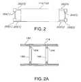
- FIG. 2is a top-outline view of a platen.
- FIG. 2Ashows a portion of an exemplary safety-belt system of the system, connected to grooves of the platens.
- FIG. 3shows a cut-away view of a COG assembly illustrating the dual-rack- and pinion arrangements, gas-shock absorber, and anterior-and-posterior-platen-latch mechanisms.
- FIG. 4shows a see-through version of a COG assembly.
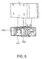
- FIG. 5shows placement of the control knobs for the hook latches of the platen latch mechanism.
- FIG. 6shows an isometric view of the posterior-platen-latch mechanism coupled to the lower rack shafts of the COG assembly and further coupled to the posterior-platen-tube assembly.
- center-of-gravityrefers to the point at which the resultant gravitational force acts upon an object.
- the center of gravityis not necessarily inside the object.
- the center of gravity of a ringis at the center of symmetry. If the geometry of the object does not change with time, the center of gravity will remain unchanged in relation to the object. In embodiments described herein, the center-of-gravity changes as patients placed in and removed from the system.
- operating tablerefers to general operating room tables, medical procedural tables, x-ray tables, and potentially other surfaces for performing a medical procedure usually under sedation and/or general anesthesia.
- over travelrefers to the distance over which the moving member(s) travel after a platen has come to rest on a support structure.
- platenrefers to an assembly having a framework and a patient support area disposed within an area defined by the framework.
- the term “anterior platen”generally refers to the platen which is configured to support the anterior side of a patient.
- anterior platengenerally refers to the platen which is configured to support the posterior side of the patient. While specific examples may refer to one or the other, it should be appreciated by those skilled in the art, that either platen is interchangeable with the other, and such terminology is not necessarily intended to limit the scope of the claims.
- pronerefers to a patient lying face downward.
- supinerefers to a patient lying face upward.
- ratchet-and-pawl systemrefers to a mechanism having the ability to back-drive in one direction and catch in the opposite direction of rotation
- a patient-safety-transfer systemconfigured to lift, rotate, and transfer a patient to/from an operating table.
- An embodiment of the patient-safety-transfer system 100is depicted in FIG. 1 .
- the primary components of system 100include a chassis 101 , powered-lift columns 102 ( 1 ), 102 ( 2 ), center-of-gravity (COG) assemblies 106 ( 1 ), 106 ( 2 ), spindle assemblies 108 ( 1 ), 108 ( 2 ), portable-caster-base assemblies 110 ( 1 ), 110 ( 2 ), a drawbar 112 , a posterior platen 114 , an anterior platen 122 , and registration plates 126 ( 1 ), 126 ( 2 ).
- COGcenter-of-gravity
- Chassis 101serves as a framework for apparatus 100 , which is configured to straddle an OR table.
- Chassis 101includes two portable-caster-base assemblies 110 ( 1 ), 110 ( 2 ).
- Portable-caster-base assemblies 110are coupled to each other by drawbar 112 .
- Drawbar 112includes an operating position, and a second collapsible-storage position. In the collapsible-storage position, drawbar 112 slidably folds together, which enables storage or transportation of system 100 .
- Powered-lift columns 102 ( 1 ), 102 ( 2 ), in embodiments described herein,are typically electrically powered, but it is appreciated by those skilled in the art having the benefit this disclosure, that these powered-lift columns are not so limited and may be powered by any suitable means including but not limited to hydraulics and pneumatics.
- 102 ( 1 ), 102 ( 2 )are located at distal ends of drawbar 112 .
- Powered-lift columns 102 ( 1 ), 102 ( 2 )vertically extend and retract allowing for adjustability in height of platens 114 and 122 . In one embodiment, the height of both powered-lift columns 102 ( 1 ), 102 ( 2 ) move in unison.
- Powered-lift columns 102may incorporate actuators (not shown) that telescopically expand and contract each column to control their height.
- FIG. 1Ashows a side view a COG assembly 106 coupled to a spindle assembly 108 , which is mounted on an inside portion of powered-lift column 102 .
- each COG assembly 106includes internal assemblies (to be described) which facilitate the securing of a patient between posterior and anterior platens 114 and 122 (shown in FIG. 1 ).
- Each COG assembly 106includes two opposing pairs of latch assemblies 160 ( 1 ), 160 ( 2 ) for releasably connecting posterior platen 114 and anterior platen 122 to system 100 . Because of the side view, in FIG. 1A , only two out of the four latch assemblies can be seen.
- FIG. 2is top-outline view of a platens 114 / 122 .
- extension telescoping shafts 2021 ), 202 ( 2 ), 202 ( 3 ), 202 ( 4 ).
- platen tubes 2041 ), 204 ( 2 ), which are generally perpendicular to the telescoping shafts 202 .
- Telescoping shafts 202slide in and out of platens 114 / 122 .
- telescoping shafts 202When connected to COG assemblies 106 ( FIG. 1 ), telescoping shafts 202 are extended several inches.
- telescoping shafts 202may be retracted so that these shafts 202 and platen tubes 204 may be coextensive or in the boundaries of the operating-table surface.
- each of latch assembly 160releasably attaches to platen tubes 204 .
- Each spindle assembly 108is mounted on a top portion of each column 102 .
- COG assembly 106is mounted to an inboard side of each spindle assembly 108 with a spindle shaft 210 allowing for rotation of the COG assembly 106 .
- COG assembly 106adjusts a latching open and shut with a dual rack and pinion device to open both or close both posterior and anterior shafts simultaneously.
- a platen latch assemblyis mounted to each end of the COG assembly in order to manually lock onto the platen tubes.
- Each COG assemblyhas one platen latch assembly for the posterior platen and one latch assembly for the anterior platen.
- One posterior platenis used for the posterior side of patients and has two telescoping shafts to provide a safety distance (approximately 6.0 inches) between the COG platen latches and the patient, while the patient is lying on the platen. Platen tube extensions can be collapsed when a transfer or rotation is complete in order to provide patient access during an operating room procedure.
- One anterior platenis used for the anterior side of patients and also has two telescoping devices to provide patients a safe distance away from the COG assembly during the hook-up phase of the transfer.
- One safety belt systemis used to engage the posterior platen and the anterior platens together for the rotate, or patient turning, phase. Referring back to FIG.
- occipital padding 170 and a leg bolster 172may be placed on a planar surface of anterior platen 122 to support the head and legs respectively when a patient lies on his back on the surface of platen 114 , and provide friction support to secure the patient disposed between the platens 114 / 122 , when rotated 180 degrees.
- Anterior platen 122includes a removable head-support assembly (not shown), a torso support 174 , and leg pads 176 and 178 which support the patient while laying in a prone position, and provide friction support to secure the patient disposed between the platens 114 / 122 , when rotated 180 degrees.
- Torso support 174 and leg pads 176 , 178are attached to rails 180 ( 1 ), 180 ( 2 ), and can slide longitudinally along rails 180 via brackets 182 that fit around rails 180 .
- a groove 184 located on each side of platens 114 , 122permits a safety-belt system (one or more safety belts 186 ) to be slidably attached to grooves 184 of both platens 114 , 122 .
- FIG. 2Ashows a side view of a portion of platens 114 , 122 showing an exemplary safety-belt system connected to grooves 184 . Because the release latches of each safety belt 186 are attached proximal or directly to at least one groove 184 of a platen (in this example 114 ), only one portion of the two-piece belts may hang down or be conveniently folded under/over a platen 114 / 122 and out of the way when not in use.
- safety beltsuse mushroom-head pins.
- side padding 190may be attached to portions of one or more safety belts to fasten the arms of a patient and provide
- Torso support 174consists two pads in the general shape of Wilson-styled chest frame which supports the outer portions of the side of patient. These pads extend from the upper thighs to the shoulders of a patient. The height of the center portion of the torso support is adjustable by a manual or powered crank system.
- system 100eliminates the need for operating room staff to manually lift and place patient on and off an operating table.
- Various embodiments disclosed hereininclude several mechanical elements, assemblies and subsystems, such as, but not limited to, dual-rack-and-pinion subsystems, lost-motion devices, gas-shock absorbers, and ratchet-and-pawl subsystems. These mechanical elements, assemblies, and subsystems are combined in a unique manner to provide a patient-safety-transfer system 100 operable to safely rotate a patient from a supine to prone position, and from a prone to supine position.
- each of theseallow a top set of racks to extend simultaneously with a lower set of racks comprising the dual-rack-and-pinions.
- Thisis used in each COG assembly (described in greater detail below) and provides a self-centering function.
- the driven loadstops moving when it contacts a fixed stop and the powered device (i.e., columns 102 ) continue to lower in a free state.
- Gas-shock absorbersare used to counter-act large weights in many mechanisms such as a rear hatch door in a vehicle.
- the gas-shock absorbersare sized to each application in order to reduce free energy caused by gravity as well as provide an ergonomic, realistic amount of energy for human beings to safely perform a given manual function, such as, rotating a patient from supine to prone and vice versa.
- Ratchet-and-pawl systemsprovide mechanisms with the ability to back-drive in one direction and catch in the opposite direction of rotation as is used in COG assemblies 106 .
- Pre-stage conditions for an illustrative embodiment of the present inventionare set as listed below in order to facilitate detailed descriptions of the specifics of the lowering function, latching of COG to posterior and anterior platens, COG self centering features, COG assembly self-centering-ratchet-and-pawl functions, and finally the spindle lost motion functions. More particularly, the pre-stage conditions are: (1) posterior platen 114 is manually pre-staged onto the OR table and each telescopic end 202 ( FIG. 2 ) of platen 114 is advanced into a locked position; (2) a patient is positioned on top of posterior platen 114 for rotation into the prone position; (3) the upper and lower dual-rack-and-pinion shafts 302 and 303 ( FIGS.
- each COG assemblyis extended and locked into their fully extended positions; (4) anterior-platen 122 is already locked onto its respective latches 160 ( FIG. 1A ) and is rotated in a ready-to-receive position over the top of the patient lying on posterior platen 114 and operating table (not shown); (5) portable-caster-base assemblies 110 have already been located to posterior platen 114 with registration plate 126 mounted to inbound portion of columns 102 ; and (6) casters are locked in-position.
- a staff member of the hospital or similar facilitycontrols a pendant-control panel (not shown) in order to lift or lower platens onto or off from the operating table.
- a pendant button for loweringWhen the pendant button for lowering is actuated, both columns 102 lift and lower simultaneously with respect to each other. The pendant button is depressed and the two lift columns lower the COG assemblies 106 .
- Latch mechanisms 160 mounted on each of the COG assembliesfully nest over the platen tubes 204 ( FIG. 1A ) during this downward motion.
- dual-rack-and-pinion system of COG assemblies 106begins to close and a release mechanism of a ratchet-and-pawl assembly begins to back drive and platens 114 / 122 adjust themselves to the size of patient (vertical thickness).
- anterior-platen-foam pads(such as on torso support 174 and leg pads 176 , 178 depicted in FIG. 1 ) eventually make contact with the patient and a controlled patient pad compression is reached.
- Posterior platen 114is manually latched onto dual rack and pinion shafts 301 , 302 ( FIG. 1A and FIG. 3 ) of the COG assembly 106 .
- safety belts 186FIGS. 1 and 2A ) are attached and cinched to redundantly secure the patient (in addition to the compression of the padding against the front and back of the patient).
- the lift and rotate functionsare achieved.
- Spindle assembly 108mounts on a top portion of lift column 102 .
- spindle assemblies 108stay in contact with the top portion of lift column 102 , and therefore COG assemblies (each coupled to the inboard spindle 210 ( FIG. 1A ) of each of the spindle assembly 108 ) and platens 114 / 122 (each coupled to platen-latch mechanisms 160 ( FIG. 1A ) of COG assemblies 106 ), are raised.
- spindle assemblies 108stay in contact with the top portion of their respective lift columns 102 , and therefore the COG assemblies 106 and platens 114 / 122 are lowered.
- An adjustable COG assembly 106is mounted to the inboard side of each spindle assembly 108 with a spindle 210 allowing for rotation of COG assembly 106 .
- an illustrative COG assembly 106is shown with an upper pair of rack shafts 301 a and 301 b at least partially disposed within a housing 302 of COG assembly 106 .
- Rack shafts 301 a and 301 bare spaced apart from each other by a first distance, and are also each coupled to an anterior-platen latch 315 .
- a lower pair of rack shafts 303 a and 303 bare at least partially disposed within housing 302 .
- Lower pair of rack shafts 303 a and 303 bare spaced apart from each other by a second distance, and are also each coupled to a posterior-platen latch 316 .
- Rack shafts 301 a and 303 aare each coupled to a pinion gear 306 a to form a first dual rack and pinion arrangement.
- Rack shafts 301 b and 303 bare each coupled to a pinion gear 306 b to form a second dual rack and pinion arrangement.
- a gas-shock absorber 314is disposed in housing 302 and has a piston 310 coupled to anterior platen latch 315 .
- a release knob 304provides a mechanism to release rack shafts 301 a , 303 a , 301 b , 303 b in order to expand to their fully extended positions.
- Latch hooks 308are mounted to anterior platen latch 315 , and in operation latch onto the frame of an anterior platen.
- Latch hooks 309are mounted to posterior-platen latch 316 , and in operation latch onto the frame of a posterior platen.
- a latch-and-pawl-system disposed within housing 302provides a mechanism for the rack and pinion system to collapse and back-drive the pawl mechanism in one direction (i.e., collapse direction of the racks).
- COG assembly 106adjusts open and shut with a dual-rack-and-pinion device to open both or close both posterior and anterior shafts simultaneously.
- platen latch assemblies 315 , 316are mounted to each end respectively of the COG to manually lock onto the platen frames. There is one latch assembly for the posterior platen and one latch assembly for the anterior platen.
- Gas-shock absorber 310performs two functions. The first function is to expand the COG assembly 106 to pre-stage for a pick-up condition. The second function is to provide a metered support force onto a platen (usually the upper platen) when columns 102 are lowering and platen pads make contact with the patient. These shock absorbers 310 will support the majority of the weight of spindle assemblies 108 , COG assemblies 106 , and a portion of the anterior or posterior platens 114 / 122 .
- Each end of COG assembly 106has a platen-latch assembly (anterior platen latch 315 and posterior platen latch 316 respectively).
- staff members, or operatorsmanually turn either one of knobs 502 ( FIG. 5 ) on either side of the posterior-platen latch to engage and clamp onto the lower platen tube assembly 602 ( FIG. 6 ).
- Final patient compressionis validated by pressing down on both sides of the anterior platen and attaching belt systems between the posterior and anterior platens.
- FIG. 4shows a see-through version of COG assembly 106 .
- a system for turning a patient from a supine to prone position and from a prone to supine positionincludes a first-lifting column having top end and a bottom end; a second-lifting column having a top end and a bottom end; a first-spindle assembly disposed over the top end of the first-lifting column; a second spindle-assembly disposed over the top end of the second-lifting column; a first-COG assembly coupled to the first-spindle assembly; a second-COG assembly coupled to the second-spindle assembly; a posterior platen having a first-frame assembly, the first-frame assembly coupled to a posterior-platen latch assembly of the first-COG assembly, and further coupled to a posterior-platen-latch assembly of the second-COG assembly; an anterior platen having a second frame assembly, the second-frame assembly coupled to an anterior-platen latch assembly of the first-COG assembly, and further coupled
- Some embodimentsalso include a first-caster base coupled to the bottom end of the first-lifting column; and a second-caster base coupled to the bottom end of the second lifting column.
- Still other embodimentsinclude a drawbar coupled between the first-caster base and the second-caster base, wherein the drawbar is operable to maintain the coupling of the first and the second-lifting columns while changing the distance between the first and the second-lifting columns by telescoping.
- each COG assemblyincludes a housing; am upper pair of racks, each disposed at least partially within the housing, each coupled to one of a corresponding first pair of pinions, and each of the upper pair of racks spaced apart from each other by a first distance; a lower pair of racks, each disposed at least partially within the housing, each coupled to one of a corresponding second pair of pinions, and each of the lower pair of racks spaced apart from each other by a second distance; wherein the first distance is greater than the second distance.
- an apparatus suitable for forming part of a patient turning systemincludes a COG assembly coupled to a spindle, thereby allowing the COG assembly to rotate about an axis defined by the spindle; a spindle assembly upon which the spindle is attached; a lifting column having a first end and a second end, with the spindle assembly disposed upon the first end; and a caster base to which the second end of the lifting column is attached.
- the caster baseincludes an attachment point for a drawbar.
- the lifting columnis operable to move the spindle assembly thereby changing the vertical position of the spindle assembly.
- the COG assemblyincludes a housing; an upper pair of rack shafts, each disposed at least partially within the housing, each coupled to one of a pair of pinion gears, and each of the upper pair of racks spaced apart from each other by a first distance; a lower pair of rack shafts, each disposed at least partially within the housing, each coupled to one of the pair of pinion gears, and each of the lower pair of racks spaced apart from each other by a second distance; and a gas shock absorber, disposed in the housing and mechanically connected to the anterior-platen-latch assembly; wherein the first distance is greater than the second distance; and wherein a first one of the upper pair of rack shafts and a first one of the lower pair of rack shafts are each coupled to a first-pinion gear of the pair of pinion gears in a first-dual-rack
- the exemplary methods and apparatus illustrated and described hereinfind application in at least the field of patient safety transport systems.
Landscapes
- Health & Medical Sciences (AREA)
- Life Sciences & Earth Sciences (AREA)
- Animal Behavior & Ethology (AREA)
- General Health & Medical Sciences (AREA)
- Public Health (AREA)
- Veterinary Medicine (AREA)
- Nursing (AREA)
- Engineering & Computer Science (AREA)
- Biomedical Technology (AREA)
- Accommodation For Nursing Or Treatment Tables (AREA)
Abstract
Description
Claims (19)
Priority Applications (1)
| Application Number | Priority Date | Filing Date | Title |
|---|---|---|---|
| US13/776,576US9233037B2 (en) | 2009-04-01 | 2013-02-25 | Patient rotation apparatus |
Applications Claiming Priority (3)
| Application Number | Priority Date | Filing Date | Title |
|---|---|---|---|
| US16589709P | 2009-04-01 | 2009-04-01 | |
| US12/753,050US8381331B2 (en) | 2009-04-01 | 2010-04-01 | Patient-rotation system with center-of-gravity assembly |
| US13/776,576US9233037B2 (en) | 2009-04-01 | 2013-02-25 | Patient rotation apparatus |
Related Parent Applications (1)
| Application Number | Title | Priority Date | Filing Date |
|---|---|---|---|
| US12/753,050ContinuationUS8381331B2 (en) | 2009-04-01 | 2010-04-01 | Patient-rotation system with center-of-gravity assembly |
Publications (2)
| Publication Number | Publication Date |
|---|---|
| US20140150178A1 US20140150178A1 (en) | 2014-06-05 |
| US9233037B2true US9233037B2 (en) | 2016-01-12 |
Family
ID=43123552
Family Applications (2)
| Application Number | Title | Priority Date | Filing Date |
|---|---|---|---|
| US12/753,050Active2031-03-08US8381331B2 (en) | 2009-04-01 | 2010-04-01 | Patient-rotation system with center-of-gravity assembly |
| US13/776,576ActiveUS9233037B2 (en) | 2009-04-01 | 2013-02-25 | Patient rotation apparatus |
Family Applications Before (1)
| Application Number | Title | Priority Date | Filing Date |
|---|---|---|---|
| US12/753,050Active2031-03-08US8381331B2 (en) | 2009-04-01 | 2010-04-01 | Patient-rotation system with center-of-gravity assembly |
Country Status (1)
| Country | Link |
|---|---|
| US (2) | US8381331B2 (en) |
Cited By (7)
| Publication number | Priority date | Publication date | Assignee | Title |
|---|---|---|---|---|
| US10363189B2 (en) | 2015-10-23 | 2019-07-30 | Allen Medical Systems, Inc. | Surgical patient support for accommodating lateral-to-prone patient positioning |
| EP3533431A1 (en)* | 2018-02-28 | 2019-09-04 | Allen Medical Systems, Inc. | Surgical patient support and methods thereof |
| US10492973B2 (en) | 2015-01-05 | 2019-12-03 | Allen Medical Systems, Inc. | Dual modality prone spine patient support apparatuses |
| US10548793B2 (en) | 2016-06-14 | 2020-02-04 | Allen Medical Systems, Inc. | Pinless loading for spine table |
| US10561559B2 (en) | 2015-10-23 | 2020-02-18 | Allen Medical Systems, Inc. | Surgical patient support system and method for lateral-to-prone support of a patient during spine surgery |
| US11241350B2 (en) | 2018-08-31 | 2022-02-08 | Hill-Rom Services, Inc. | Patient turning system |
| US11471354B2 (en) | 2018-08-30 | 2022-10-18 | Allen Medical Systems, Inc. | Patient support with selectable pivot |
Families Citing this family (49)
| Publication number | Priority date | Publication date | Assignee | Title |
|---|---|---|---|---|
| US9295433B2 (en) | 2005-02-22 | 2016-03-29 | Roger P. Jackson | Synchronized patient elevation and positioning apparatus for use with patient positioning support systems |
| US9265679B2 (en) | 2005-02-22 | 2016-02-23 | Roger P Jackson | Cantilevered patient positioning support structure |
| US9744087B2 (en) | 2005-02-22 | 2017-08-29 | Roger P. Jackson | Patient support apparatus with body slide position digitally coordinated with hinge angle |
| US9308145B2 (en) | 2005-02-22 | 2016-04-12 | Roger P. Jackson | Patient positioning support structure |
| US8844077B2 (en)* | 2005-02-22 | 2014-09-30 | Roger P. Jackson | Syncronized patient elevation and positioning apparatus positioning support systems |
| US9186291B2 (en) | 2005-02-22 | 2015-11-17 | Roger P. Jackson | Patient positioning support structure with trunk translator |
| US7739762B2 (en) | 2007-10-22 | 2010-06-22 | Mizuho Orthopedic Systems, Inc. | Surgery table apparatus |
| US7565708B2 (en) | 2005-02-22 | 2009-07-28 | Jackson Roger P | Patient positioning support structure |
| US8707484B2 (en) | 2005-02-22 | 2014-04-29 | Roger P. Jackson | Patient positioning support structure |
| US20150059094A1 (en) | 2005-02-22 | 2015-03-05 | Roger P. Jackson | Patient positioning support structure |
| US9468576B2 (en) | 2005-02-22 | 2016-10-18 | Roger P. Jackson | Patient support apparatus with body slide position digitally coordinated with hinge angle |
| US9301897B2 (en) | 2005-02-22 | 2016-04-05 | Roger P. Jackson | Patient positioning support structure |
| US10869798B2 (en) | 2006-05-05 | 2020-12-22 | Warsaw Orthopedic, Inc. | Patient positioning support apparatus with virtual pivot-shift pelvic pads, upper body stabilization and fail-safe table attachment mechanism |
| US9642760B2 (en) | 2006-05-05 | 2017-05-09 | Roger P. Jackson | Patient positioning support apparatus with virtual pivot-shift pelvic pads, upper body stabilization and fail-safe table attachment mechanism |
| US9339430B2 (en)* | 2006-05-05 | 2016-05-17 | Roger P. Jackson | Patient positioning support apparatus with virtual pivot-shift pelvic pads, upper body stabilization and fail-safe table attachment mechanism |
| US8381331B2 (en)* | 2009-04-01 | 2013-02-26 | Operating Room Safety Enterprises, LLC | Patient-rotation system with center-of-gravity assembly |
| US8016305B2 (en)* | 2009-05-29 | 2011-09-13 | Jin Sun Gee Plastics Co., Ltd. | Height adjustment mechanism for baby walker |
| US8370972B2 (en)* | 2009-07-01 | 2013-02-12 | Fredrick C Shriver | Supine lift and stretcher |
| WO2013058806A1 (en) | 2011-10-17 | 2013-04-25 | Jackson Roger P | Patient positioning support structure |
| US9561145B2 (en) | 2012-02-07 | 2017-02-07 | Roger P. Jackson | Fail-safe release mechanism for use with patient positioning support apparati |
| US9498397B2 (en) | 2012-04-16 | 2016-11-22 | Allen Medical Systems, Inc. | Dual column surgical support system |
| ITMI20121546A1 (en) | 2012-09-18 | 2014-03-19 | Medacta Int Sa | ADAPTER FLOOR FOR SURGICAL TABLE, IN PARTICULAR FOR REPLACEMENT OPERATIONS OF THE HOOK WITH FRONT APPROACH |
| GB2515113B (en)* | 2013-06-14 | 2015-12-30 | Eschmann Holdings Ltd | Surgical table and method of operating the same |
| US12011399B2 (en) | 2013-08-28 | 2024-06-18 | Warsaw Orthopedic, Inc. | Patient positioning support apparatus with fail-safe connector attachment mechanism |
| DE102014100444B4 (en)* | 2014-01-16 | 2017-06-29 | MAQUET GmbH | Device for linear displacement of a patient support surface and method for mounting such a device |
| DE102014202033B4 (en)* | 2014-02-05 | 2017-07-06 | Siemens Healthcare Gmbh | Mobile medical device and method for controlling movement of the mobile medical device |
| US9549863B2 (en) | 2014-07-07 | 2017-01-24 | Roger P. Jackson | Surgical table with pivoting and translating hinge |
| US9402775B2 (en) | 2014-07-07 | 2016-08-02 | Roger P. Jackson | Single and dual column patient positioning and support structure |
| US10149793B2 (en)* | 2015-02-04 | 2018-12-11 | Stephen Hoel | Adjustable support apparatus for a surgery table |
| US9700476B2 (en)* | 2015-02-06 | 2017-07-11 | Mizuho Orthopedic Systems, Inc. | Patient platform connection device |
| US10426684B2 (en) | 2015-06-11 | 2019-10-01 | Allen Medical Systems, Inc. | Person support apparatuses including person repositioning assemblies |
| US10857054B2 (en) | 2015-11-13 | 2020-12-08 | Allen Medical Systems, Inc. | Person support apparatuses for subject repositioning |
| AU2016201158A1 (en)* | 2016-02-24 | 2017-09-07 | Stephen Hoel | Surgery table attachment apparatus |
| AU2016201155B2 (en)* | 2016-02-24 | 2019-07-04 | Mizuho Orthopedic Systems, Inc. | An adjustable support apparatus for a surgery table |
| EP3216437A1 (en)* | 2016-03-08 | 2017-09-13 | Stephen Hoel | An adjustable support apparatus for a surgery table |
| US10576006B2 (en)* | 2017-06-30 | 2020-03-03 | Warsaw Orthopedic, Inc. | Surgical frame having translating lower beam and method for use thereof |
| US11213448B2 (en) | 2017-07-31 | 2022-01-04 | Allen Medical Systems, Inc. | Rotation lockout for surgical support |
| US10835439B2 (en) | 2018-08-21 | 2020-11-17 | Warsaw Orthopedic, Inc. | Surgical frame having translating lower beam and moveable linkage or surgical equipment attached thereto and method for use thereof |
| US10893996B2 (en) | 2018-08-22 | 2021-01-19 | Warsaw Orthopedic, Inc. | Surgical frame having translating lower beam and moveable linkage or surgical equipment attached thereto and method for use thereof |
| CN109998833B (en)* | 2019-04-04 | 2021-02-02 | 山东大学 | Shifting machine |
| US12207957B2 (en)* | 2020-10-28 | 2025-01-28 | Warsaw Orthopedic, Inc. | Surgical frame incorporating electro-magnetic imaging device in combination with radiation-mitigation system |
| US12121479B1 (en)* | 2021-04-16 | 2024-10-22 | Turn Medical, LLC | Strap and release system |
| CN114081741A (en)* | 2021-11-22 | 2022-02-25 | 王书珍 | Emergency treatment is with being convenient for neural severe patient prone position appearance of ventilating |
| CN115105317B (en)* | 2022-06-28 | 2024-04-12 | 周问艳 | Rehabilitation protector with fall protection function and fracture prevention function |
| US12011397B2 (en) | 2022-08-26 | 2024-06-18 | EMPLASE Medical Technologies, LLC | Patient-positioning system, computer-control and data-integration system, surgical componentry, and surgical methods of using same |
| US12396909B2 (en) | 2022-08-29 | 2025-08-26 | Warsaw Orthopedic, Inc. | Surgical platform system |
| CN115869143B (en)* | 2022-11-30 | 2025-08-08 | 中国人民解放军总医院 | An airborne rescue system |
| CN117462359B (en)* | 2023-11-29 | 2024-07-16 | 山东大学齐鲁医院 | Operating table for pitching and overturning of user and using method thereof |
| CN117357359B (en)* | 2023-12-07 | 2024-02-23 | 吉林大学 | Operating table capable of adaptively adjusting bed surface and control method thereof |
Citations (37)
| Publication number | Priority date | Publication date | Assignee | Title |
|---|---|---|---|---|
| US3202218A (en) | 1962-06-18 | 1965-08-24 | Gray Tool Co | Submergible apparatus for underwater operations |
| US3238539A (en)* | 1962-09-05 | 1966-03-08 | Koch Albert | Rotatable beds for invalids |
| US3302218A (en)* | 1965-05-28 | 1967-02-07 | Stryker Corp | Turning frame |
| US3750659A (en) | 1972-05-01 | 1973-08-07 | D Loomans | Orthopedic apparatus for legs to enable standing |
| US3827089A (en)* | 1971-09-16 | 1974-08-06 | W Grow | Turnover bed assembly |
| US4029089A (en) | 1976-06-14 | 1977-06-14 | Mulholland Lawrence K | Prone stander |
| US4114209A (en)* | 1977-05-31 | 1978-09-19 | Sandlin Joseph P | Tilting attachment for a bed |
| US4244358A (en)* | 1979-09-10 | 1981-01-13 | Noel Pyers | Rollover bed having pallet with flex points and constant traction maintaining apparatus |
| US4296761A (en) | 1980-04-25 | 1981-10-27 | Camp International, Inc. | Convertible parapodium |
| USD307055S (en) | 1987-02-12 | 1990-04-03 | Johnston Malcolm C | Standing frame for the handicapped |
| US4937901A (en)* | 1988-11-04 | 1990-07-03 | Brennan Louis G | Apparatus for turning a patient from a supine to a prone position and vice-versa |
| US5103511A (en)* | 1990-03-01 | 1992-04-14 | Hector Sequin | Oscillatory bed |
| US5131106A (en)* | 1990-08-30 | 1992-07-21 | Jackson Roger P | Spinal surgery table |
| USD347604S (en) | 1992-09-11 | 1994-06-07 | R82 A/S | Mobile support furniture |
| USD356527S (en) | 1993-05-14 | 1995-03-21 | Bissell Inc. | Multi-position body support |
| US5489258A (en) | 1993-05-14 | 1996-02-06 | Bissell Inc. | Multi-position body support |
| US5618055A (en) | 1995-04-21 | 1997-04-08 | Mulholland Designs, Inc. | Stander |
| US6154901A (en) | 1997-09-26 | 2000-12-05 | New York Society For The Relief Of The Ruptured And Crippled Maintaining The Hospital For Special Surgery | Spinal-surgery table |
| US20020138906A1 (en)* | 2001-03-29 | 2002-10-03 | Bartlett Alan L. | Prone positioning therapeutic bed |
| US6526610B1 (en) | 1998-06-26 | 2003-03-04 | Hill-Rom Services, Inc. | Proning bed |
| US6941951B2 (en) | 2003-10-17 | 2005-09-13 | Labelle Hubert | Dynamic frame for prone surgical positioning |
| US7036512B2 (en) | 2003-06-25 | 2006-05-02 | Prodije 9061-7457 Quebec Inc. | Dismountable multi-position stander |
| US20060242765A1 (en)* | 2004-11-10 | 2006-11-02 | Skripps Thomas K | Accessory frame for spinal surgery |
| US7137160B2 (en)* | 1999-04-21 | 2006-11-21 | Hill-Rom Services, Inc. | Proning bed |
| US7152261B2 (en) | 2005-02-22 | 2006-12-26 | Jackson Roger P | Modular multi-articulated patient support system |
| US7197778B2 (en)* | 2004-06-14 | 2007-04-03 | Patient Safety Transport Systems Gp, Llc | Patient transfer system |
| US20070113336A1 (en)* | 2005-11-19 | 2007-05-24 | Patient Safety Transport Systems Gp, Llc | Back surgery platform |
| US20070174966A1 (en)* | 2004-02-17 | 2007-08-02 | Rodrigo Lopez-Sansalvador | Rotating therapeutic bed |
| US20070192960A1 (en) | 2005-02-22 | 2007-08-23 | Jackson Roger P | Patient positioning support structure |
| US7343916B2 (en) | 2000-07-14 | 2008-03-18 | Hill-Rom Services, Inc. | Pulmonary therapy apparatus |
| US7520008B2 (en) | 2004-11-10 | 2009-04-21 | Allen Medical Systems | Surgical table extension |
| US7614639B2 (en) | 2004-10-12 | 2009-11-10 | Invacare Corporation | Modular standing frame |
| US20100024128A1 (en) | 2004-11-10 | 2010-02-04 | Skripps Thomas K | Body support apparatus for spinal surgery |
| USD612942S1 (en) | 2008-04-11 | 2010-03-30 | Gay Mary Verdon-Roe | Head stabilizing support |
| US20100293713A1 (en)* | 2009-04-01 | 2010-11-25 | Lewis Sharps | Patient-rotation system with center-of- gravity assembly |
| US20110083273A1 (en)* | 2009-04-01 | 2011-04-14 | Patient Safety Transport Systems, Llc | Apparatuses For Posterior Surgery |
| US20110219544A1 (en)* | 2010-02-19 | 2011-09-15 | Howard Johnston | Oscillating bed |
- 2010
- 2010-04-01USUS12/753,050patent/US8381331B2/enactiveActive
- 2013
- 2013-02-25USUS13/776,576patent/US9233037B2/enactiveActive
Patent Citations (42)
| Publication number | Priority date | Publication date | Assignee | Title |
|---|---|---|---|---|
| US3202218A (en) | 1962-06-18 | 1965-08-24 | Gray Tool Co | Submergible apparatus for underwater operations |
| US3238539A (en)* | 1962-09-05 | 1966-03-08 | Koch Albert | Rotatable beds for invalids |
| US3302218A (en)* | 1965-05-28 | 1967-02-07 | Stryker Corp | Turning frame |
| US3827089A (en)* | 1971-09-16 | 1974-08-06 | W Grow | Turnover bed assembly |
| US3750659A (en) | 1972-05-01 | 1973-08-07 | D Loomans | Orthopedic apparatus for legs to enable standing |
| US4029089A (en) | 1976-06-14 | 1977-06-14 | Mulholland Lawrence K | Prone stander |
| US4114209A (en)* | 1977-05-31 | 1978-09-19 | Sandlin Joseph P | Tilting attachment for a bed |
| US4244358A (en)* | 1979-09-10 | 1981-01-13 | Noel Pyers | Rollover bed having pallet with flex points and constant traction maintaining apparatus |
| US4296761A (en) | 1980-04-25 | 1981-10-27 | Camp International, Inc. | Convertible parapodium |
| USD307055S (en) | 1987-02-12 | 1990-04-03 | Johnston Malcolm C | Standing frame for the handicapped |
| US4937901A (en)* | 1988-11-04 | 1990-07-03 | Brennan Louis G | Apparatus for turning a patient from a supine to a prone position and vice-versa |
| US5103511A (en)* | 1990-03-01 | 1992-04-14 | Hector Sequin | Oscillatory bed |
| US5131106A (en)* | 1990-08-30 | 1992-07-21 | Jackson Roger P | Spinal surgery table |
| USD347604S (en) | 1992-09-11 | 1994-06-07 | R82 A/S | Mobile support furniture |
| USD356527S (en) | 1993-05-14 | 1995-03-21 | Bissell Inc. | Multi-position body support |
| US5489258A (en) | 1993-05-14 | 1996-02-06 | Bissell Inc. | Multi-position body support |
| US5618055A (en) | 1995-04-21 | 1997-04-08 | Mulholland Designs, Inc. | Stander |
| US6154901A (en) | 1997-09-26 | 2000-12-05 | New York Society For The Relief Of The Ruptured And Crippled Maintaining The Hospital For Special Surgery | Spinal-surgery table |
| US6526610B1 (en) | 1998-06-26 | 2003-03-04 | Hill-Rom Services, Inc. | Proning bed |
| US7137160B2 (en)* | 1999-04-21 | 2006-11-21 | Hill-Rom Services, Inc. | Proning bed |
| US7343916B2 (en) | 2000-07-14 | 2008-03-18 | Hill-Rom Services, Inc. | Pulmonary therapy apparatus |
| US20020138906A1 (en)* | 2001-03-29 | 2002-10-03 | Bartlett Alan L. | Prone positioning therapeutic bed |
| US7036512B2 (en) | 2003-06-25 | 2006-05-02 | Prodije 9061-7457 Quebec Inc. | Dismountable multi-position stander |
| US6941951B2 (en) | 2003-10-17 | 2005-09-13 | Labelle Hubert | Dynamic frame for prone surgical positioning |
| US20070174966A1 (en)* | 2004-02-17 | 2007-08-02 | Rodrigo Lopez-Sansalvador | Rotating therapeutic bed |
| US7653953B2 (en)* | 2004-02-17 | 2010-02-02 | Ciateq, A.C. | Rotating therapeutic bed |
| US7197778B2 (en)* | 2004-06-14 | 2007-04-03 | Patient Safety Transport Systems Gp, Llc | Patient transfer system |
| US7614639B2 (en) | 2004-10-12 | 2009-11-10 | Invacare Corporation | Modular standing frame |
| US7520008B2 (en) | 2004-11-10 | 2009-04-21 | Allen Medical Systems | Surgical table extension |
| US20100024128A1 (en) | 2004-11-10 | 2010-02-04 | Skripps Thomas K | Body support apparatus for spinal surgery |
| US20060242765A1 (en)* | 2004-11-10 | 2006-11-02 | Skripps Thomas K | Accessory frame for spinal surgery |
| US20070192960A1 (en) | 2005-02-22 | 2007-08-23 | Jackson Roger P | Patient positioning support structure |
| US7343635B2 (en)* | 2005-02-22 | 2008-03-18 | Jackson Roger P | Modular multi-articulated patient support system |
| US20090282614A1 (en) | 2005-02-22 | 2009-11-19 | Jackson Roger P | Patient positioning support structure |
| US7152261B2 (en) | 2005-02-22 | 2006-12-26 | Jackson Roger P | Modular multi-articulated patient support system |
| US20070113336A1 (en)* | 2005-11-19 | 2007-05-24 | Patient Safety Transport Systems Gp, Llc | Back surgery platform |
| USD612942S1 (en) | 2008-04-11 | 2010-03-30 | Gay Mary Verdon-Roe | Head stabilizing support |
| US20100293713A1 (en)* | 2009-04-01 | 2010-11-25 | Lewis Sharps | Patient-rotation system with center-of- gravity assembly |
| US20110083273A1 (en)* | 2009-04-01 | 2011-04-14 | Patient Safety Transport Systems, Llc | Apparatuses For Posterior Surgery |
| US8381331B2 (en)* | 2009-04-01 | 2013-02-26 | Operating Room Safety Enterprises, LLC | Patient-rotation system with center-of-gravity assembly |
| US8707476B2 (en)* | 2009-04-01 | 2014-04-29 | Operating Room Safety Enterprises, LLC | Apparatuses for posterior surgery |
| US20110219544A1 (en)* | 2010-02-19 | 2011-09-15 | Howard Johnston | Oscillating bed |
Non-Patent Citations (3)
| Title |
|---|
| "Radiolucent Wilson Frame", Orthopedic Systems, Inc. (OSI), Poster, 1998, 1 page. |
| Allen Medical Systems, "Intraoperative Adjustment from Kyphosis to Lordosis", Announcement Allen Medical Systems, Feb. 6, 2006, pp. 1-4. |
| The PCT Search Report mailed Apr. 26, 2012 for PCT Application No. PCT/US2010/052740. |
Cited By (14)
| Publication number | Priority date | Publication date | Assignee | Title |
|---|---|---|---|---|
| US10492973B2 (en) | 2015-01-05 | 2019-12-03 | Allen Medical Systems, Inc. | Dual modality prone spine patient support apparatuses |
| US11096853B2 (en) | 2015-10-23 | 2021-08-24 | Allen Medical Systems, Inc. | Surgical patient support for accommodating lateral-to-prone patient positioning |
| US12403055B2 (en) | 2015-10-23 | 2025-09-02 | Allen Medical Systems, Inc. | Surgical patient support for lateral-to-prone patient positioning |
| US10363189B2 (en) | 2015-10-23 | 2019-07-30 | Allen Medical Systems, Inc. | Surgical patient support for accommodating lateral-to-prone patient positioning |
| US10561559B2 (en) | 2015-10-23 | 2020-02-18 | Allen Medical Systems, Inc. | Surgical patient support system and method for lateral-to-prone support of a patient during spine surgery |
| US10792207B2 (en) | 2015-10-23 | 2020-10-06 | Allen Medical Systems, Inc. | Lateral-to-prone spine surgery table |
| US10548793B2 (en) | 2016-06-14 | 2020-02-04 | Allen Medical Systems, Inc. | Pinless loading for spine table |
| US11202731B2 (en) | 2018-02-28 | 2021-12-21 | Allen Medical Systems, Inc. | Surgical patient support and methods thereof |
| US20220087887A1 (en)* | 2018-02-28 | 2022-03-24 | Allen Medical Systems, Inc. | Surgical patient support and methods thereof |
| EP4029486A1 (en)* | 2018-02-28 | 2022-07-20 | Allen Medical Systems, Inc. | Surgical patient support and methods thereof |
| US12220359B2 (en)* | 2018-02-28 | 2025-02-11 | Allen Medical Systems, Inc. | Surgical patient support and methods thereof |
| EP3533431A1 (en)* | 2018-02-28 | 2019-09-04 | Allen Medical Systems, Inc. | Surgical patient support and methods thereof |
| US11471354B2 (en) | 2018-08-30 | 2022-10-18 | Allen Medical Systems, Inc. | Patient support with selectable pivot |
| US11241350B2 (en) | 2018-08-31 | 2022-02-08 | Hill-Rom Services, Inc. | Patient turning system |
Also Published As
| Publication number | Publication date |
|---|---|
| US8381331B2 (en) | 2013-02-26 |
| US20140150178A1 (en) | 2014-06-05 |
| US20100293713A1 (en) | 2010-11-25 |
Similar Documents
| Publication | Publication Date | Title |
|---|---|---|
| US9233037B2 (en) | Patient rotation apparatus | |
| US8707476B2 (en) | Apparatuses for posterior surgery | |
| US7496980B2 (en) | Operating table conversion platform | |
| US7197778B2 (en) | Patient transfer system | |
| US8046851B2 (en) | Patient single surface system | |
| US8176584B2 (en) | Patient-support apparatus with movable top | |
| US9265680B2 (en) | Surgical table | |
| US8042208B2 (en) | Rotational operating table | |
| US6266831B1 (en) | Storable trauma board support | |
| US9474671B2 (en) | Surgical table | |
| CA2626491C (en) | Patient transfer system with operating table conversion platform | |
| WO2011062713A1 (en) | Apparatuses for posterior surgery | |
| CN209808776U (en) | Automatic transfer bed for medical care patient | |
| US20230190576A1 (en) | Chest compression system retainer with rigid brace for use with a patient transport apparatus | |
| MX2008006974A (en) | Patient single surface system | |
| KR20230126268A (en) | Bed for carrying patients and fixing method thereof |
Legal Events
| Date | Code | Title | Description |
|---|---|---|---|
| STCF | Information on status: patent grant | Free format text:PATENTED CASE | |
| AS | Assignment | Owner name:THOMAS H. MARTIN, UNITED STATES Free format text:ASSIGNMENT OF ASSIGNORS INTEREST;ASSIGNOR:OPERATING ROOM SAFETY ENTERPRISES, LLC;REEL/FRAME:045743/0146 Effective date:20170814 Owner name:WARSAW ORTHOPEDIC, INC, INDIANA Free format text:ASSIGNMENT OF ASSIGNORS INTEREST;ASSIGNOR:THOMAS H. MARTIN;REEL/FRAME:045745/0145 Effective date:20170815 | |
| MAFP | Maintenance fee payment | Free format text:PAYMENT OF MAINTENANCE FEE, 4TH YR, SMALL ENTITY (ORIGINAL EVENT CODE: M2551); ENTITY STATUS OF PATENT OWNER: SMALL ENTITY Year of fee payment:4 | |
| AS | Assignment | Owner name:PATIENT SAFETY TRANSPORT SYSTEMS, LLC, PENNSYLVANIA Free format text:ASSIGNMENT OF ASSIGNORS INTEREST;ASSIGNOR:SHARPS, LEWIS;REEL/FRAME:055871/0336 Effective date:20100726 Owner name:CONTOUR FABRICATORS, INC., MICHIGAN Free format text:ASSIGNMENT OF ASSIGNORS INTEREST;ASSIGNOR:ROMIG, ALAN DEAN;REEL/FRAME:055871/0325 Effective date:20100611 Owner name:PATIENT SAFETY TRANSPORT SYSTEMS, LLC, PENNSYLVANIA Free format text:ASSIGNMENT OF ASSIGNORS INTEREST;ASSIGNOR:CONTOUR FABRICATORS, INC.;REEL/FRAME:055871/0368 Effective date:20100826 Owner name:OPERATING ROOM SAFETY ENTERPRISES, LLC, PENNSYLVANIA Free format text:CHANGE OF NAME;ASSIGNOR:PATIENT SAFETY TRANSPORT SYSTEMS, LLC;REEL/FRAME:055871/0395 Effective date:20110922 | |
| FEPP | Fee payment procedure | Free format text:ENTITY STATUS SET TO UNDISCOUNTED (ORIGINAL EVENT CODE: BIG.); ENTITY STATUS OF PATENT OWNER: LARGE ENTITY | |
| MAFP | Maintenance fee payment | Free format text:PAYMENT OF MAINTENANCE FEE, 8TH YEAR, LARGE ENTITY (ORIGINAL EVENT CODE: M1552); ENTITY STATUS OF PATENT OWNER: LARGE ENTITY Year of fee payment:8 |