US9233007B2 - Expandable self-anchoring interbody cage for orthopedic applications - Google Patents
Expandable self-anchoring interbody cage for orthopedic applicationsDownload PDFInfo
- Publication number
- US9233007B2 US9233007B2US13/766,562US201313766562AUS9233007B2US 9233007 B2US9233007 B2US 9233007B2US 201313766562 AUS201313766562 AUS 201313766562AUS 9233007 B2US9233007 B2US 9233007B2
- Authority
- US
- United States
- Prior art keywords
- cage
- interbody cage
- screw
- biologics
- wedge
- Prior art date
- Legal status (The legal status is an assumption and is not a legal conclusion. Google has not performed a legal analysis and makes no representation as to the accuracy of the status listed.)
- Expired - Fee Related, expires
Links
Images


Classifications
- A—HUMAN NECESSITIES
- A61—MEDICAL OR VETERINARY SCIENCE; HYGIENE
- A61F—FILTERS IMPLANTABLE INTO BLOOD VESSELS; PROSTHESES; DEVICES PROVIDING PATENCY TO, OR PREVENTING COLLAPSING OF, TUBULAR STRUCTURES OF THE BODY, e.g. STENTS; ORTHOPAEDIC, NURSING OR CONTRACEPTIVE DEVICES; FOMENTATION; TREATMENT OR PROTECTION OF EYES OR EARS; BANDAGES, DRESSINGS OR ABSORBENT PADS; FIRST-AID KITS
- A61F2/00—Filters implantable into blood vessels; Prostheses, i.e. artificial substitutes or replacements for parts of the body; Appliances for connecting them with the body; Devices providing patency to, or preventing collapsing of, tubular structures of the body, e.g. stents
- A61F2/02—Prostheses implantable into the body
- A61F2/30—Joints
- A61F2/44—Joints for the spine, e.g. vertebrae, spinal discs
- A61F2/442—Intervertebral or spinal discs, e.g. resilient
- A—HUMAN NECESSITIES
- A61—MEDICAL OR VETERINARY SCIENCE; HYGIENE
- A61F—FILTERS IMPLANTABLE INTO BLOOD VESSELS; PROSTHESES; DEVICES PROVIDING PATENCY TO, OR PREVENTING COLLAPSING OF, TUBULAR STRUCTURES OF THE BODY, e.g. STENTS; ORTHOPAEDIC, NURSING OR CONTRACEPTIVE DEVICES; FOMENTATION; TREATMENT OR PROTECTION OF EYES OR EARS; BANDAGES, DRESSINGS OR ABSORBENT PADS; FIRST-AID KITS
- A61F2/00—Filters implantable into blood vessels; Prostheses, i.e. artificial substitutes or replacements for parts of the body; Appliances for connecting them with the body; Devices providing patency to, or preventing collapsing of, tubular structures of the body, e.g. stents
- A61F2/02—Prostheses implantable into the body
- A61F2/30—Joints
- A61F2/44—Joints for the spine, e.g. vertebrae, spinal discs
- A61F2/4455—Joints for the spine, e.g. vertebrae, spinal discs for the fusion of spinal bodies, e.g. intervertebral fusion of adjacent spinal bodies, e.g. fusion cages
- A61F2/447—Joints for the spine, e.g. vertebrae, spinal discs for the fusion of spinal bodies, e.g. intervertebral fusion of adjacent spinal bodies, e.g. fusion cages substantially parallelepipedal, e.g. having a rectangular or trapezoidal cross-section
- A—HUMAN NECESSITIES
- A61—MEDICAL OR VETERINARY SCIENCE; HYGIENE
- A61F—FILTERS IMPLANTABLE INTO BLOOD VESSELS; PROSTHESES; DEVICES PROVIDING PATENCY TO, OR PREVENTING COLLAPSING OF, TUBULAR STRUCTURES OF THE BODY, e.g. STENTS; ORTHOPAEDIC, NURSING OR CONTRACEPTIVE DEVICES; FOMENTATION; TREATMENT OR PROTECTION OF EYES OR EARS; BANDAGES, DRESSINGS OR ABSORBENT PADS; FIRST-AID KITS
- A61F2/00—Filters implantable into blood vessels; Prostheses, i.e. artificial substitutes or replacements for parts of the body; Appliances for connecting them with the body; Devices providing patency to, or preventing collapsing of, tubular structures of the body, e.g. stents
- A61F2/02—Prostheses implantable into the body
- A61F2/28—Bones
- A61F2002/2835—Bone graft implants for filling a bony defect or an endoprosthesis cavity, e.g. by synthetic material or biological material
- A—HUMAN NECESSITIES
- A61—MEDICAL OR VETERINARY SCIENCE; HYGIENE
- A61F—FILTERS IMPLANTABLE INTO BLOOD VESSELS; PROSTHESES; DEVICES PROVIDING PATENCY TO, OR PREVENTING COLLAPSING OF, TUBULAR STRUCTURES OF THE BODY, e.g. STENTS; ORTHOPAEDIC, NURSING OR CONTRACEPTIVE DEVICES; FOMENTATION; TREATMENT OR PROTECTION OF EYES OR EARS; BANDAGES, DRESSINGS OR ABSORBENT PADS; FIRST-AID KITS
- A61F2/00—Filters implantable into blood vessels; Prostheses, i.e. artificial substitutes or replacements for parts of the body; Appliances for connecting them with the body; Devices providing patency to, or preventing collapsing of, tubular structures of the body, e.g. stents
- A61F2/02—Prostheses implantable into the body
- A61F2/30—Joints
- A61F2002/30001—Additional features of subject-matter classified in A61F2/28, A61F2/30 and subgroups thereof
- A61F2002/30316—The prosthesis having different structural features at different locations within the same prosthesis; Connections between prosthetic parts; Special structural features of bone or joint prostheses not otherwise provided for
- A61F2002/30329—Connections or couplings between prosthetic parts, e.g. between modular parts; Connecting elements
- A61F2002/30476—Connections or couplings between prosthetic parts, e.g. between modular parts; Connecting elements locked by an additional locking mechanism
- A61F2002/30507—Connections or couplings between prosthetic parts, e.g. between modular parts; Connecting elements locked by an additional locking mechanism using a threaded locking member, e.g. a locking screw or a set screw
- A—HUMAN NECESSITIES
- A61—MEDICAL OR VETERINARY SCIENCE; HYGIENE
- A61F—FILTERS IMPLANTABLE INTO BLOOD VESSELS; PROSTHESES; DEVICES PROVIDING PATENCY TO, OR PREVENTING COLLAPSING OF, TUBULAR STRUCTURES OF THE BODY, e.g. STENTS; ORTHOPAEDIC, NURSING OR CONTRACEPTIVE DEVICES; FOMENTATION; TREATMENT OR PROTECTION OF EYES OR EARS; BANDAGES, DRESSINGS OR ABSORBENT PADS; FIRST-AID KITS
- A61F2/00—Filters implantable into blood vessels; Prostheses, i.e. artificial substitutes or replacements for parts of the body; Appliances for connecting them with the body; Devices providing patency to, or preventing collapsing of, tubular structures of the body, e.g. stents
- A61F2/02—Prostheses implantable into the body
- A61F2/30—Joints
- A61F2002/30001—Additional features of subject-matter classified in A61F2/28, A61F2/30 and subgroups thereof
- A61F2002/30316—The prosthesis having different structural features at different locations within the same prosthesis; Connections between prosthetic parts; Special structural features of bone or joint prostheses not otherwise provided for
- A61F2002/30535—Special structural features of bone or joint prostheses not otherwise provided for
- A61F2002/30537—Special structural features of bone or joint prostheses not otherwise provided for adjustable
- A61F2002/30556—Special structural features of bone or joint prostheses not otherwise provided for adjustable for adjusting thickness
- A—HUMAN NECESSITIES
- A61—MEDICAL OR VETERINARY SCIENCE; HYGIENE
- A61F—FILTERS IMPLANTABLE INTO BLOOD VESSELS; PROSTHESES; DEVICES PROVIDING PATENCY TO, OR PREVENTING COLLAPSING OF, TUBULAR STRUCTURES OF THE BODY, e.g. STENTS; ORTHOPAEDIC, NURSING OR CONTRACEPTIVE DEVICES; FOMENTATION; TREATMENT OR PROTECTION OF EYES OR EARS; BANDAGES, DRESSINGS OR ABSORBENT PADS; FIRST-AID KITS
- A61F2/00—Filters implantable into blood vessels; Prostheses, i.e. artificial substitutes or replacements for parts of the body; Appliances for connecting them with the body; Devices providing patency to, or preventing collapsing of, tubular structures of the body, e.g. stents
- A61F2/02—Prostheses implantable into the body
- A61F2/30—Joints
- A61F2/30767—Special external or bone-contacting surface, e.g. coating for improving bone ingrowth
- A61F2/30771—Special external or bone-contacting surface, e.g. coating for improving bone ingrowth applied in original prostheses, e.g. holes or grooves
- A61F2002/30772—Apertures or holes, e.g. of circular cross section
Definitions
- the field of the inventionrelates generally to interbody spinal fusion implants configured to correct an angular relationship between vertebrae.
- Implant systems utilizing specially designed spinal instrumentationare often used in surgical procedures concerning spinal conditions. Such implants are used to correct degenerative conditions and facilitate spinal fusion while stabilizing and strengthening the spine. Spinal fusion is the joining of adjacent vertebrae through shared bone. Degenerative conditions which often require spinal fusion surgery include spondylolisthesis, chronic degenerative disc disease, traumatic fractures, and other forms of spinal instability such as scoliosis.
- Degenerative conditionsmay lead to the spinal cord or nerve roots being squeezed as to cause difficulty with back pain, numbness or weakness in one or all extremities, difficulty with instability and gait, as well as clumsiness and proprioception. In extreme cases, certain degenerative conditions can also lead to losing control over the bladder or bowels.
- Implant systems used in spinal fusion surgerycan be summarized into the following groups: rods; pedicle screws; hooks; plates; and interbody cages.
- Rodsare used in conjunction with hooks and screws to immobilize involved spinal levels and to contour the spine to correct alignment. Screws are implanted into the pedicles of the spinal vertebrae to provide strong anchorage points for rods, which can then be contoured to correct deformities to facilitate spinal fusion. Hooks are used with rods and other implants to anchor them to the vertebrae. Plates, often used in the cervical spine, are designed to conform to the contour of the spine, and are held in place by screws set into adjacent vertebrae.
- Interbody cagesare small, hollow devices packed with bone graft or other osteogenic fusion graft material (i.e., biologics) used to restore lost disc height between two vertebrae.
- a problem that is encountered when using interbody cages in spinal fusion surgeryis that current devices are bulky, difficult to introduce through an incision into the disc and cannot be expanded, anchored or filled with biologics in situ.
- current devicesare designed by engineers on a naked spine, which necessarily lacks an appreciation for the true conditions of spinal fusion surgery. For example, nerve compression, root injury, dural tears and spinal fluid leaks are frequently produced by oversized interbody cages that are significantly larger in size than the entry point allowed by the axilla of the nerve root, which may result in compression of the dorsal root ganglion.
- Oversized interbody cagesare often needed to accommodate a large disc space, but current devices are inserted via a small entry point, which is bordered by the spinal dura (medially), nerve root and dorsal root ganglion (cranially), pedicle (caudally), and in case of posterior lumbar interbody fusion, the residual lamina (laterally), which is usually removed when transforamenal interbody fusion is done. In some cases this can result in significant post-operative pain and/or neurologic deficit.
- Another problem with current devicesis that they do not fully permit biologics to be injected into interbody cages in situ. Current devices also have problems with revision, adjustment and repositioning when placed in the spine, and cannot be coupled with another interbody cage in situ.
- the present inventionis designed to maintain lordosis in the human spine.
- the interbody cage of the present inventionmay be expanded to fit within the disc space created by the removal of disc material between two adjacent vertebrae.
- the present inventionis significantly easier to use than current devices because it is smaller, and can be introduced into the spine posteriorly or anteriorly in one step through a minimally invasive approach to the spine, and can then be expanded, anchored, or coupled with another interbody cage, and filled with biologics while in situ.
- the present inventioncan be coupled with another expandable interbody cage of the present invention or with a stationary cage both before placement in the body and in situ, which improves functionality and versatility over current devices. These features decrease surgical time, effort and complications.
- the present inventionis designed to expand up to eighty percent (80%) of its initial size in one or two directions (cranially or caudally). This expandable feature allows the present invention to fit wholly in the space created by the removal of the disc material between two adjacent vertebrae, without the need to first inject biologics into the space between the vertebral bodies.
- the present inventionhas the ability to be distracted and anchored while it situ, it provides an increase of the foramenal size; hence, a better decompression of the nerve root, and also a decreased incidence of dislodgment in the immediate post-operative period.
- the ability to introduce biologics in the present invention solely after it is expandeddecreases the dead space left within the interbody cage, and improves the contact of the biologics with the endplates, which ultimately may result in improved fusion rates.
- the ability to couple the interbody cage in situ with either another expandable or a fixed-length interbody cagealso provides options for designing longer anterior constructs via a posterior approach.
- the present inventioncan also be readily re-engaged, adjusted or removed, depending on the specific surgical need, and has a thirty percent (30%) wider foot print than current devices in the medio-lateral direction.
- the present inventionis useful in the cervical, thoracic and lumbar areas of the spine; however, said invention may only be introduced into the cervical spine through an anterior approach.
- the present inventionmay be introduced through a posterior, posterolateral, lateral or strait anterior approach.
- the present inventionmay be manipulated while under the dural surface because the entry point can be wider in lateral direction and narrower craniocaudally. This permits the present invention to be of a rectangular shape rather than a square shape, thus allowing safer and better retraction of the dura medially.
- one embodiment of the present inventioncomprises spinal fusion intervertebral implant that includes an insertion/injection handle; a threaded rod; an interbody cage with upper and lower body portions; a screw; a horizontal slotted wedge; and two vertical sliding tapped wedges, such that in elevational side view, the present invention has the shape of a bullet.
- the interbody cageis comprised of an additional horizontal slotted wedge.
- the insertion/injection handle of the present inventionis a hollow tube with a long internal allen or star-shaped shaft designed to accept a threaded rod.
- the insertion/injection handlehas, at one end, a knurled top and threaded collar.
- the opposing end of the insertion/injection handlemay have a male-threaded fitting, with an internal female-thread, to allow the insertion/injection handle to achieve a flush attachment to a threaded collar on one end of the interbody cage.
- the opposing end of the insertion/injection handlemay have a female-threaded fitting, with an internal male-thread to achieve a flush attachment to the interbody cage.
- the insertion/injection handlecan be packaged with the interbody cage preloaded on the insertion/injection tool.
- the threaded rod of the present inventionis a long allen or star-shaped shaft, which is inserted into the insertion/injection handle and used as a screwdriver to rotate a screw within the interbody cage.
- the threaded rodhas, at one end, a knurled top to allow rotation by hand or external tool.
- the opposing end of the threaded rodterminates with a depression on the top of the screw, located within the interbody cage.
- the interbody cageis the body of the present invention, and can be fabricated from any material, including surgical metals, plastics or human bone, with PEEK being the preferred embodiment. It is not preferable that the interbody cage be fabricated from titanium because this material does not permit orthopedic surgeons to assess the endplate bone growth in order to assess the fusion rate. As compared to current devices fabricated from titanium, the present invention will provide the benefit of better fusion rates because PEEK allows it to be more pliable, which makes its elasticity resemble that of human bone.
- the interbody cageis a rectangular structure of uniform height in elevation view, with a trapezoid-shaped bullet nose on the leading end of said cage.
- the interbody cagehas no solid upper or lower surface, which, in plan-view, exposes the screw within that operates the horizontal and vertical wedges.
- the interbody cageis designed to allow for movement of opposing horizontal and vertical wedges within said cage from the rotation of a screw which is pre-fixed inside said cage.
- the opposing end of the interbody cagehas a threaded collar designed to attach to the insertion/injection handle. From plan-view, the opposing end of the interbody cage reveals the head of the screw.
- the dimensions of the interbody cagevary, depending on whether the present invention is implanted in the cervical, thoracic, or lumbar spine, and whether the interbody cage is collapsed, partially expanded, or fully expanded.
- the interbody cage used in the cervical spinewill have a depth and width range of 10-20 mm and a height range of 5-10 mm.
- the interbody cage used in the thoracic spinewill have a depth and width range of 15-30 mm and a height range of 7-18 mm.
- the interbody cage used in the lumbar spinewill have a depth range of 20-35 mm, a width range of 10-40 mm, and a height range of 7-18 mm.
- the interbody cagehas two embodiments, allowing said cage to expand in one direction or two opposing directions.
- the interbody cagecan be of any shape or width to accommodate the disc space between two vertebral bodies, to maintain or correct lordosis.
- the interbody cagemay also have tabs or key holes on either side adjacent to the leading or opposing end of said cage to couple with other expandable or fixed interbody cages to allow for further expansion.
- the screw of the present inventionis solid, fabricated from titanium, and has an allen or star-shaped depression on the head of said screw that attaches to the end of the threaded rod.
- the screwis threaded through openings in both vertical sliding tapped wedges located within the interbody cage.
- the screwis secured with a threaded collar at one or both ends such that it can only be rotated, but not move vertically.
- the screwruns the entire length of the interbody cage and penetrates the nose of the interbody cage.
- the leading end of the screwis flattened to maintain its horizontal position in the interbody cage when being rotated by the threaded rod.
- the horizontal slotted wedge of the present inventionis a slotted wedge that is free to lift from the body of the interbody cage as said wedge is displaced by the vertical sliding tapped wedges.
- the horizontal slotted wedgehas internal stop pins that cause said wedge to stop moving at its maximum expansion, as to prevent said wedge from fully separating from the cage.
- the depth, shape and slope of the horizontal slotted wedgeare variable to achieve an almost infinite range of adjustment.
- the edges of the horizontal slotted wedge that ultimately make contact with the vertical sliding tapped wedgesare channeled or serrated to account for friction.
- two horizontal slotted wedgesare provided that travel in opposing directions.
- the vertical sliding tapped wedges of the present inventionare wedges, fabricated from titanium, situated in opposing ends of the interbody cage with threaded openings configured to accept the screw, which is pre-fixed inside said cage.
- the vertical sliding tapped wedgesare configured to face each other, and are generally sloped at the top so as to create an angle when contacting the horizontal slotted wedge.
- the vertical sliding tapped wedgeswill thread onto the screw to a maximum position of halfway down the screw.
- the vertical sliding tapped wedge located nearest the leading edge of the cageis reversed tapped to permit said wedge to move towards the opposing wedge as the screw is rotated by the threaded rod.
- the depth, shape and slope of the vertical sliding tapped wedgesare variable. The edges of the vertical tapped sliding wedges that ultimately make contact with the horizontal wedge is channeled or serrated to account for friction.
- a nurse or surgeonattaches the insertion/injection handle to the threaded collar on a fully collapsed interbody cage by rotating said handle until it becomes flush with the opposing end of the interbody cage.
- the nurse or surgeonwould first attach additional expandable or fixed interbody cages to the initial interbody cage by coupling said cages together utilizing the tabs or key holes on the initial cage.
- the threaded rodis then inserted through the hollow opening of the insertion/injection handle, and aligned with the depression in the head of the screw.
- the surgeonthen places the interbody cage through the incision and in the preferred location within the spine, causing only minimal trauma to the surrounding soft tissue of neural structures. Once in place, the threaded rod is then rotated to operate the screw within the interbody cage.
- the nurse or surgeonconfirms that the interbody cage is in the correct location by use of internal, external and radiographic markers.
- the horizontal and vertical wedges within the interbody cageare operated.
- the vertical sliding tapped wedges on both ends of the interbody cageare forced closer together, gradually displacing the horizontal slotted wedge, which then moves in a ninety degree direction as it expands one edge of said cage outward.
- the present inventioncan also be anchored by deploying a set of anchoring pins 3 mm or more in length, cranio-caudally. This can be utilized in all areas of the spine.
- the fact that the present invention has the ability to self-anchormeans that it can be used in the thoracic and lumbar spine with all of the available approaches (i.e., posterior, anterior, lateral).
- the threaded rodis turned in the opposite direction, gradually releasing the vertical sliding tapped wedges to permit compression of the edge of said cage that expanded.
- the biologic materialcan be of surgeon's choice: bone, healos, DBM, BMP, allograft, autograft, etc.
- the biologicsflow down the hollow shaft of the insertion/injection handle and enters the interbody cage through the threaded collar at the opposing end of said cage.
- the channeled or serrated feature of the horizontal and vertical wedgespermits biologics to pass between said wedges.
- the procedurewill be largely simplified as there will be no need to remove the antero-lateral osteophytes. This requires less usage of electrocaurery, which will potentially diminish the risk of injury to the posterior pelvic plexus and the rate of retrograde ejaculation. Also the need for less dissection and retraction needed on the major vessels (i.e., aorta/vena cava) will decrease the risk of injury to these structures.
- the present inventionhas the ability to auto-adjust to the lordosis or kyphosis of the spine up to twelve (12) degrees in the antero-posterior direction.
- lordosis or kyphosis of the spineup to twelve (12) degrees in the antero-posterior direction.
- FIG. 1is a perspective view of the expandable interbody cage in an expanded state. Applicants hereby suggest that FIG. 1 be included on the front page of the patent application publication and the patent.
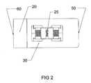
- FIG. 2is a top view of the expandable interbody cage shown in FIG. 1 in an expanded state.
- FIG. 3is a bottom view of the expandable interbody cage shown in FIG. 1 in an expanded state.
- FIG. 4is a side elevation view of the trailing end of the expandable interbody cage shown in FIG. 1 in an expanded state.
- FIG. 5is a side elevation view of the leading end of the expandable interbody cage shown in FIG. 1 in an expanded state.
- FIG. 6is a side cross-sectional view of the expandable interbody cage shown in FIG. 1 in an expanded state.
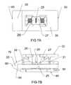
- FIG. 7Ais a top view of the expandable interbody cage shown in FIG. 1 in an expanded state.
- FIG. 7Bis a side cross-sectional view of the expandable interbody cage shown in FIG. 7A in an expanded state.
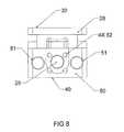
- FIG. 8is a side elevation view of the trailing end of the expandable interbody cage shown in FIG. 1 in an expanded state.
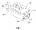
- FIG. 9is a perspective view of the expandable interbody cage shown in FIG. 1 in an expanded state.
- FIG. 10Ais a top view of the expandable interbody cage shown in FIG. 1 in an expanded state.
- FIG. 10Bis a side cross-sectional view of the expandable interbody cage shown in FIG. 10B in an expanded state.
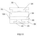
- FIG. 11is a side elevation view of the leading end of the expandable interbody cage shown in FIG. 1 in an expanded state.
- FIG. 12is a perspective view of the expandable interbody cage shown in FIG. 1 in an expanded state.
- FIG. 13is a side elevation view of the expandable interbody cage shown in FIG. 1 , wherein the leading end and expandable horizontal wedge of said cage is not shown.
- FIG. 14is a perspective view of the expandable interbody cage shown in FIG. 13
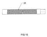
- FIG. 15is an enlarged view of an embodiment of the screw inner member of the expandable interbody cage.
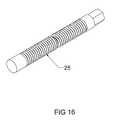
- FIG. 16is a perspective view of an embodiment of the screw inner member of the expandable interbody cage.
- FIG. 17is a top view of an embodiment of a vertical tapped sliding wedge inner member of the expandable interbody cage.
- FIG. 18is a side elevation view of an embodiment of a vertical tapped sliding wedge inner member of the expandable interbody cage shown in FIG. 17 .
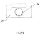
- FIG. 19is a side elevation view of an embodiment of a vertical tapped sliding wedge inner member of the expandable interbody cage shown in FIG. 17 .
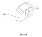
- FIG. 20is a perspective view of an embodiment of a vertical tapped sliding wedge inner member of the expandable interbody cage shown in FIG. 17 .
- FIG. 21is a top view of an embodiment of a vertical tapped sliding wedge inner member of the expandable interbody cage.
- FIG. 22is a side elevation view of an embodiment of a vertical tapped sliding wedge inner member of the expandable interbody cage shown in FIG. 21 .
- FIG. 23is a perspective view of an embodiment of a vertical tapped sliding wedge inner member of the expandable interbody cage shown in FIG. 21 .
- FIG. 24is a side elevation view of an embodiment of a vertical tapped sliding wedge inner member of the expandable interbody cage shown in FIG. 21 .
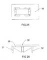
- FIG. 25is a top view of an embodiment of the expandable horizontal wedge of the expandable interbody cage shown in FIG. 1 .
- FIG. 26is a side elevation view of an embodiment of the expandable horizontal wedge of the expandable interbody cage shown in FIG. 25 .
- FIG. 27is a perspective view of an embodiment of the expandable horizontal wedge of the expandable interbody cage shown in FIG. 25 .
- FIG. 28is a side elevation view of an embodiment of the expandable horizontal wedge of the expandable interbody cage shown in FIG. 25 .
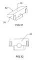
- FIG. 29is a top view of an embodiment of the leading end of the expandable interbody cage shown in FIG. 1 .
- FIG. 30is a side elevation view of an embodiment of the leading end of the expandable interbody cage shown in FIG. 29 .
- FIG. 31is a perspective view of an embodiment of the leading end of the expandable interbody cage shown in FIG. 29 .
- FIG. 32is a side elevation view of an embodiment of the leading end of the expandable interbody cage shown in FIG. 29 .
- the expandable interbody cage 10is shown, which generally has a rectangular configuration with a flat top surface 30 , a flat bottom surface 40 and a flat leading end 60 bullet nose 20 in a trapezoidal configuration with solid surfaces 60 , 70 , and 80 , as shown in FIGS. 5 and 6 .
- the top surface 30is parallel to the bottom surface 40
- the expandable interbody cage 10is an unexpanded or slightly expanded state, as shown in FIGS. 4 and 5 .
- the top surface 30 and the bottom surface 40form a support structure for bearing against adjacent vertebrae and when in a fully expanded state commensurate with the needs of a patient, the expandable interbody cage 10 creates an angular relationship is created that maintains the desired lordosis of the human spine.
- the top surface 30 and the bottom surface 40are not solid, but rather, both have a 14 mm ⁇ 6 mm rectangular opening that exposes the screw 25 and the vertical tapped sliding wedges 26 and 27 , within.
- This hollow openingprovides for bone growth to occur from the vertebrae through the openings to the internal chamber of the expandable interbody cage 10 after biologics are injected while in situ. The injection of the biologics into the expandable interbody cage 10 serves to promote bone growth.
- the trailing end 50 of the expandable interbody cage 10is a flat surface with two penetrations 51 with 3 mm diameter that are configured to accept an insertion tool that is used to place the expandable interbody cage 10 in situ.
- the trailing end 50is also configured with four penetrations 52 of 1.5 mm in diameter, which permit biologics to flow from the insertion tool into the interior of the expandable interbody cage 10 .
- the penetrations 51 , 52 at the trailing end 50are generally round in configuration, it is within the scope of the present invention that the penetrations 51 , 52 may have any size, shape, configuration, and distribution suitable for the present invention's intended purpose.
- the screw 25is 3 mm in diameter and accessed and rotated via the trialing end 50 by use of a threaded rod, which, when rotated, activates the vertical tapped sliding wedges 26 , 27 to create an angular relationship with the horizontal slotted wedge 28 , to force said wedge to expand from the expandable interbody cage 10 to any height in its preferred embodiment of 5-18 mm.
- the sides 90 and 100 of the expandable interbody cage 10are solid rectangular shapes that are configured to be parallel.
- FIG. 6a side cross-sectional view is shown.
- the assembly process for the present inventioncommences with installing the vertical sliding tapped wedges 26 and 27 on the screw 25 .
- the screw/wedge assembly 25 , 26 , 27is then inserted into the body of the expandable interbody cage 10 , with the screw 25 protruding the tailing end 50 of the expandable interbody cage 10 .
- the bullet nose 20is then pressed onto the expandable interbody cage 10 .
- the screw/wedge assembly 25 , 26 , 27then gets inserted into to bullet nose 20 , with the vertical sliding tapped wedges 26 , 27 positioned into the closed position.
- the present inventionTo install the horizontal slotted wedge 28 , the present invention must be turned onto its side, where said wedge 28 is inserted into one side of the expandable interbody cage 10 and over the screw 25 . The horizontal slotted wedge 28 can then be snapped into the body of the expandable interbody cage 10 .
- the screw 25is designed to penetrate the bullet nose 20 of the leading end 60 , which, when rotated, causes the vertical tapped sliding wedges 26 , 27 to converge towards the center of the expandable interbody cage 10 , which in turn, activates the horizontal slotted wedge 28 .
- the horizontal slotted wedge 28expands with the convergence of the vertical tapped sliding wedges 26 , 27 either until the desired height is achieved or the wedges 26 , 27 reach their maximum convergence point wherein the horizontal slotted wedge 28 is fully expanded to its maximum height of 18 mm.
- FIGS. 7B and 10Ba cross-sectional view is shown that depicts the horizontal slotted wedge 28 at its maximum height.
- the expandable interbody cage 10is implanted in the body in an unexpanded state.
- the threaded rodis engaged with the screw 25 from the trailing end 50 , causing the vertical tapped sliding wedges 26 , 27 to converge, the risers 31 , 32 , of the horizontal slotted wedge 28 converge upward until the desired expansion height is achieved.
- the expandable interbody cage 10is shown, wherein the leading end 60 , bullet nose, 20 , expandable horizontal wedge 28 , vertical tapped sliding wedges 26 , 27 , and screw 25 are not shown.
- the leading end 60 , bullet nose, 20 , expandable horizontal wedge 28 , vertical tapped sliding wedges 26 , 27 , and screw 25are not shown.
- FIG. 14there is an opening at the trailing end 50 of the expandable interbody cage 10 that is designed to accept the screw 25 that operates the vertical tapped sliding wedges 26 , 27 and the horizontal slotted wedge 28 .
- the screw 25 of the preferred embodiment of the expandable interbody cage 10is shown.
- the screw 25is configured to prevent the vertical tapped sliding wedges 26 , 27 from converging past the mid-way point on the screw 25 , which those in the art will appreciate that this feature ensures that the horizontal slotted wedge 28 will expand at a uniform height.
- the screw 25is a continuous component having threads disposed thereon.
- FIGS. 17 through 24enlarged fragmentary views of the vertical tapped sliding wedges 26 , 27 are shown, illustrating the angular configuration of said wedges 26 , 27 and the opening 24 of said wedges 26 , 27 that permits the screw to thread there through, causing said wedges 26 , 27 to converge towards each other.
- FIGS. 25 through 28enlarged fragmentary views of the rectangular-shaped horizontal slotted wedge 28 of the expandable interbody cage 10 are shown, which also serves as the top surface 30 of said cage 10 .
- the horizontal slotted wedge 28acts as a containment chamber for the biologics that are injected via penetrations 52 at the trailing end 50 of said cage 10 .
- the horizontal slotted wedge 28has risers 31 , 32 that touch the bottom surface 40 of the expandable interbody cage 10 while it is in an unexpanded state or rises a distance above the bottom surface 40 when said cage 10 is in an expanded state.
- risers 31 and 32are simply at rest and flush with bottom surface 40 , and are not connected or anchored to said bottom surface 40 .
- FIGS. 29 through 32enlarged fragmentary views of the bullet nose 20 of the expandable interbody cage 10 are shown, which can be removed from said cage 10 as shown in FIGS. 13 and 14 .
- One flat side of the bullet nose 20serves as the leading end 20 of the expandable interbody cage 10
- one flat side 70serves as the top angle of the bullet nose 20
- the other side 80serves as the bottom angle of said bullet nose 20 .
- the bullet shape of the leading end 20as opposed to a flat shape, encourages ease of placement of the expandable interbody cage 10 in its desired position adjacent to vertebrae in the spine.
Landscapes
- Health & Medical Sciences (AREA)
- Engineering & Computer Science (AREA)
- Biomedical Technology (AREA)
- Neurology (AREA)
- Orthopedic Medicine & Surgery (AREA)
- Cardiology (AREA)
- Oral & Maxillofacial Surgery (AREA)
- Transplantation (AREA)
- Heart & Thoracic Surgery (AREA)
- Vascular Medicine (AREA)
- Life Sciences & Earth Sciences (AREA)
- Animal Behavior & Ethology (AREA)
- General Health & Medical Sciences (AREA)
- Public Health (AREA)
- Veterinary Medicine (AREA)
- Prostheses (AREA)
- Surgical Instruments (AREA)
Abstract
Description
Claims (21)
Priority Applications (1)
| Application Number | Priority Date | Filing Date | Title |
|---|---|---|---|
| US13/766,562US9233007B2 (en) | 2012-02-13 | 2013-02-13 | Expandable self-anchoring interbody cage for orthopedic applications |
Applications Claiming Priority (2)
| Application Number | Priority Date | Filing Date | Title |
|---|---|---|---|
| US201261597865P | 2012-02-13 | 2012-02-13 | |
| US13/766,562US9233007B2 (en) | 2012-02-13 | 2013-02-13 | Expandable self-anchoring interbody cage for orthopedic applications |
Publications (2)
| Publication Number | Publication Date |
|---|---|
| US20130158669A1 US20130158669A1 (en) | 2013-06-20 |
| US9233007B2true US9233007B2 (en) | 2016-01-12 |
Family
ID=48610926
Family Applications (1)
| Application Number | Title | Priority Date | Filing Date |
|---|---|---|---|
| US13/766,562Expired - Fee RelatedUS9233007B2 (en) | 2012-02-13 | 2013-02-13 | Expandable self-anchoring interbody cage for orthopedic applications |
Country Status (1)
| Country | Link |
|---|---|
| US (1) | US9233007B2 (en) |
Cited By (46)
| Publication number | Priority date | Publication date | Assignee | Title |
|---|---|---|---|---|
| US20140343677A1 (en)* | 2013-05-14 | 2014-11-20 | Spine View, Inc. | Intervertebral devices and related methods |
| US20160081814A1 (en)* | 2014-08-26 | 2016-03-24 | Atlas Spine, Inc. | Spinal implant device |
| US9788971B1 (en) | 2013-05-22 | 2017-10-17 | Nuvasive, Inc. | Expandable fusion implant and related methods |
| US9801734B1 (en) | 2013-08-09 | 2017-10-31 | Nuvasive, Inc. | Lordotic expandable interbody implant |
| US10195053B2 (en) | 2009-09-18 | 2019-02-05 | Spinal Surgical Strategies, Llc | Bone graft delivery system and method for using same |
| US10245159B1 (en) | 2009-09-18 | 2019-04-02 | Spinal Surgical Strategies, Llc | Bone graft delivery system and method for using same |
| US10278830B1 (en) | 2018-02-07 | 2019-05-07 | Zavation, Llc | Expandable orthopedic implant |
| US10617530B2 (en) | 2011-07-14 | 2020-04-14 | Seaspine, Inc. | Laterally deflectable implant |
| US10682239B2 (en)* | 2017-01-06 | 2020-06-16 | Ke Ling Biotech Limited | Expandable spinal interbody cage |
| US10973656B2 (en) | 2009-09-18 | 2021-04-13 | Spinal Surgical Strategies, Inc. | Bone graft delivery system and method for using same |
| US11013610B2 (en)* | 2017-10-18 | 2021-05-25 | Spine Wave, Inc. | Expandable anterior lumbar interbody fusion device |
| US11065127B1 (en)* | 2020-04-01 | 2021-07-20 | Hammill Medical LLC | Dual-lead thread drive screw for a lateral expanding coaxial spinal implant |
| US11116644B2 (en) | 2018-05-25 | 2021-09-14 | Mirus Llc | Multiple expansion stage interbody devices |
| US11166826B2 (en)* | 2019-11-13 | 2021-11-09 | Ossaware Biotech Co., Ltd. | Multi-section expandable device |
| US11173044B1 (en) | 2021-04-20 | 2021-11-16 | Zavation Medical Products, Llc | Expanding orthopedic implant |
| US11185420B2 (en)* | 2016-12-30 | 2021-11-30 | Tobb Ekonomi Ve Teknoloji Universitesi | Expandable cage |
| US11278423B2 (en) | 2017-09-29 | 2022-03-22 | Mirus Llc | Expandable interbody devices |
| US11285014B1 (en) | 2020-11-05 | 2022-03-29 | Warsaw Orthopedic, Inc. | Expandable inter-body device, system, and method |
| US11291554B1 (en) | 2021-05-03 | 2022-04-05 | Medtronic, Inc. | Unibody dual expanding interbody implant |
| US11304817B2 (en) | 2020-06-05 | 2022-04-19 | Neurostructures, Inc. | Expandable interbody spacer |
| US11376134B1 (en) | 2020-11-05 | 2022-07-05 | Warsaw Orthopedic, Inc. | Dual expanding spinal implant, system, and method of use |
| US11382761B2 (en) | 2020-04-11 | 2022-07-12 | Neurostructures, Inc. | Expandable interbody spacer |
| US11389303B1 (en) | 2021-10-07 | 2022-07-19 | Zavation Medical Products, Llc | Externally threaded expandable orthopedic implant |
| US11395743B1 (en) | 2021-05-04 | 2022-07-26 | Warsaw Orthopedic, Inc. | Externally driven expandable interbody and related methods |
| US11517443B2 (en) | 2020-11-05 | 2022-12-06 | Warsaw Orthopedic, Inc. | Dual wedge expandable implant, system and method of use |
| US11547575B2 (en) | 2019-09-27 | 2023-01-10 | Degen Medical, Inc. | Expandable intervertebral spacers |
| US11564724B2 (en) | 2020-11-05 | 2023-01-31 | Warsaw Orthopedic, Inc. | Expandable inter-body device, system and method |
| US11612499B2 (en) | 2021-06-24 | 2023-03-28 | Warsaw Orthopedic, Inc. | Expandable interbody implant |
| US11638653B2 (en) | 2020-11-05 | 2023-05-02 | Warsaw Orthopedic, Inc. | Surgery instruments with a movable handle |
| US11717419B2 (en) | 2020-12-10 | 2023-08-08 | Neurostructures, Inc. | Expandable interbody spacer |
| US11730608B2 (en) | 2021-07-13 | 2023-08-22 | Warsaw Orthopedic, Inc. | Monoblock expandable interbody implant |
| US11806250B2 (en) | 2018-02-22 | 2023-11-07 | Warsaw Orthopedic, Inc. | Expandable spinal implant system and method of using same |
| US11833059B2 (en) | 2020-11-05 | 2023-12-05 | Warsaw Orthopedic, Inc. | Expandable inter-body device, expandable plate system, and associated methods |
| US11850163B2 (en) | 2022-02-01 | 2023-12-26 | Warsaw Orthopedic, Inc. | Interbody implant with adjusting shims |
| US11918489B2 (en) | 2021-04-02 | 2024-03-05 | Nuvasive Inc. | Expansion driver |
| US11963881B2 (en) | 2020-11-05 | 2024-04-23 | Warsaw Orthopedic, Inc. | Expandable inter-body device, system, and method |
| US12121453B2 (en) | 2020-11-05 | 2024-10-22 | Warsaw Orthopedic, Inc. | Dual wedge expandable implant with eyelets, system, and method of use |
| US12171439B2 (en) | 2020-11-05 | 2024-12-24 | Warsaw Orthopedic, Inc. | Protected drill |
| US12239544B2 (en) | 2020-11-05 | 2025-03-04 | Warsaw Orthopedic, Inc. | Rhomboid shaped implants |
| US12268614B2 (en) | 2021-06-24 | 2025-04-08 | Warsaw Orthopedic, Inc. | Interbody implant with adjusting shims |
| US12295865B2 (en) | 2021-06-24 | 2025-05-13 | Warsaw Orthopedic, Inc. | Expandable interbody implant and corresponding inserter |
| US12318308B2 (en) | 2020-11-05 | 2025-06-03 | Warsaw Orthopedic, Inc. | Dual expandable inter-body device |
| US12318307B2 (en) | 2021-07-16 | 2025-06-03 | Blue Ocean Spine Gmbh | Adjustable spinal implants, associated instruments and methods |
| US12414863B2 (en) | 2021-06-24 | 2025-09-16 | Warsaw Orthopedic, Inc. | Expandable interbody implant and corresponding surgical tool |
| US12427036B2 (en) | 2021-04-04 | 2025-09-30 | Nuvasive, Inc. | Expandable implants |
| USD1098430S1 (en) | 2022-12-13 | 2025-10-14 | Mirus Llc | Expandable medical device |
Families Citing this family (225)
| Publication number | Priority date | Publication date | Assignee | Title |
|---|---|---|---|---|
| US7041309B2 (en) | 2002-06-13 | 2006-05-09 | Neuropro Technologies, Inc. | Spinal fusion using an HMG-CoA reductase inhibitor |
| US6793678B2 (en) | 2002-06-27 | 2004-09-21 | Depuy Acromed, Inc. | Prosthetic intervertebral motion disc having dampening |
| AU2004212942A1 (en) | 2003-02-14 | 2004-09-02 | Depuy Spine, Inc. | In-situ formed intervertebral fusion device |
| US20040267367A1 (en) | 2003-06-30 | 2004-12-30 | Depuy Acromed, Inc | Intervertebral implant with conformable endplate |
| US7753958B2 (en) | 2003-08-05 | 2010-07-13 | Gordon Charles R | Expandable intervertebral implant |
| US8636802B2 (en) | 2004-03-06 | 2014-01-28 | DePuy Synthes Products, LLC | Dynamized interspinal implant |
| US8597360B2 (en) | 2004-11-03 | 2013-12-03 | Neuropro Technologies, Inc. | Bone fusion device |
| US9456907B1 (en)* | 2005-03-24 | 2016-10-04 | Igip, Llc | Extendable spinal implant |
| US9801733B2 (en) | 2005-03-31 | 2017-10-31 | Life Spine, Inc. | Expandable spinal interbody and intravertebral body devices |
| US9526525B2 (en) | 2006-08-22 | 2016-12-27 | Neuropro Technologies, Inc. | Percutaneous system for dynamic spinal stabilization |
| WO2008070863A2 (en) | 2006-12-07 | 2008-06-12 | Interventional Spine, Inc. | Intervertebral implant |
| US8900307B2 (en) | 2007-06-26 | 2014-12-02 | DePuy Synthes Products, LLC | Highly lordosed fusion cage |
| EP2237748B1 (en) | 2008-01-17 | 2012-09-05 | Synthes GmbH | An expandable intervertebral implant |
| US8932355B2 (en) | 2008-02-22 | 2015-01-13 | Coalign Innovations, Inc. | Spinal implant with expandable fixation |
| US12232975B2 (en) | 2008-02-22 | 2025-02-25 | Howmedica Osteonics Corp. | Lockable spinal implant |
| US8696751B2 (en)* | 2008-12-10 | 2014-04-15 | Coalign Innovations, Inc. | Adjustable distraction cage with linked locking mechanisms |
| US8992620B2 (en) | 2008-12-10 | 2015-03-31 | Coalign Innovations, Inc. | Adjustable distraction cage with linked locking mechanisms |
| US20100145455A1 (en) | 2008-12-10 | 2010-06-10 | Innvotec Surgical, Inc. | Lockable spinal implant |
| US8936641B2 (en) | 2008-04-05 | 2015-01-20 | DePuy Synthes Products, LLC | Expandable intervertebral implant |
| US9526620B2 (en) | 2009-03-30 | 2016-12-27 | DePuy Synthes Products, Inc. | Zero profile spinal fusion cage |
| US8287597B1 (en) | 2009-04-16 | 2012-10-16 | Nuvasive, Inc. | Method and apparatus for performing spine surgery |
| KR101687435B1 (en) | 2009-07-06 | 2016-12-19 | 신세스 게엠바하 | Expandable fixation assemblies |
| US8556979B2 (en) | 2009-10-15 | 2013-10-15 | Globus Medical, Inc. | Expandable fusion device and method of installation thereof |
| US8062375B2 (en) | 2009-10-15 | 2011-11-22 | Globus Medical, Inc. | Expandable fusion device and method of installation thereof |
| US9155628B2 (en) | 2009-10-15 | 2015-10-13 | Globus Medical, Inc. | Expandable fusion device and method of installation thereof |
| US10806596B2 (en) | 2009-10-15 | 2020-10-20 | Globus Medical, Inc. | Expandable fusion device and method installation thereof |
| US11564807B2 (en) | 2009-10-15 | 2023-01-31 | Globus Medical, Inc. | Expandable fusion device and method of installation thereof |
| US10098758B2 (en) | 2009-10-15 | 2018-10-16 | Globus Medical, Inc. | Expandable fusion device and method of installation thereof |
| US11103366B2 (en) | 2009-10-15 | 2021-08-31 | Globus Medical, Inc. | Expandable fusion device and method of installation thereof |
| US8709086B2 (en) | 2009-10-15 | 2014-04-29 | Globus Medical, Inc. | Expandable fusion device and method of installation thereof |
| US9216095B2 (en) | 2009-10-15 | 2015-12-22 | Globus Medical, Inc. | Expandable fusion device and method of installation thereof |
| US10327917B2 (en) | 2009-10-15 | 2019-06-25 | Globus Medical, Inc. | Expandable fusion device and method of installation thereof |
| US8685098B2 (en) | 2010-06-25 | 2014-04-01 | Globus Medical, Inc. | Expandable fusion device and method of installation thereof |
| US11344430B2 (en) | 2009-10-15 | 2022-05-31 | Globus Medical, Inc. | Expandable fusion device and method of installation thereof |
| US9393129B2 (en) | 2009-12-10 | 2016-07-19 | DePuy Synthes Products, Inc. | Bellows-like expandable interbody fusion cage |
| US9381045B2 (en) | 2010-01-13 | 2016-07-05 | Jcbd, Llc | Sacroiliac joint implant and sacroiliac joint instrument for fusing a sacroiliac joint |
| US9333090B2 (en)* | 2010-01-13 | 2016-05-10 | Jcbd, Llc | Systems for and methods of fusing a sacroiliac joint |
| US9421109B2 (en) | 2010-01-13 | 2016-08-23 | Jcbd, Llc | Systems and methods of fusing a sacroiliac joint |
| WO2014015309A1 (en) | 2012-07-20 | 2014-01-23 | Jcbd, Llc | Orthopedic anchoring system and methods |
| CA3002234C (en) | 2010-01-13 | 2020-07-28 | Jcbd, Llc | Sacroiliac joint fixation fusion system |
| EP2547292B1 (en) | 2010-03-16 | 2019-04-24 | Pinnacle Spine Group, LLC | Ntervertebral implants and graft delivery systems |
| US8870880B2 (en) | 2010-04-12 | 2014-10-28 | Globus Medical, Inc. | Angling inserter tool for expandable vertebral implant |
| US8979860B2 (en) | 2010-06-24 | 2015-03-17 | DePuy Synthes Products. LLC | Enhanced cage insertion device |
| US9907560B2 (en) | 2010-06-24 | 2018-03-06 | DePuy Synthes Products, Inc. | Flexible vertebral body shavers |
| US9597200B2 (en) | 2010-06-25 | 2017-03-21 | Globus Medical, Inc | Expandable fusion device and method of installation thereof |
| US8623091B2 (en) | 2010-06-29 | 2014-01-07 | DePuy Synthes Products, LLC | Distractible intervertebral implant |
| BR112013002765A2 (en) | 2010-07-15 | 2017-09-19 | Nlt Spine Ltd | deflectable implant, system and methods for implantation |
| US10085849B2 (en) | 2010-09-03 | 2018-10-02 | Globus Medical, Inc. | Expandable fusion device and method of installation thereof |
| US10779957B2 (en) | 2010-09-03 | 2020-09-22 | Globus Medical, Inc. | Expandable fusion device and method of installation thereof |
| US9855151B2 (en) | 2010-09-03 | 2018-01-02 | Globus Medical, Inc | Expandable fusion device and method of installation thereof |
| US12059358B2 (en) | 2010-09-03 | 2024-08-13 | Globus Medical Inc. | Expandable fusion device and method of installation thereof |
| US9351848B2 (en) | 2010-09-03 | 2016-05-31 | Globus Medical, Inc. | Expandable fusion device and method of installation thereof |
| US10842644B2 (en) | 2010-09-03 | 2020-11-24 | Globus Medical, Inc. | Expandable fusion device and method of installation thereof |
| US10869768B2 (en) | 2010-09-03 | 2020-12-22 | Globus Medical Inc. | Expandable fusion device and method of installation thereof |
| US11793654B2 (en) | 2010-09-03 | 2023-10-24 | Globus Medical, Inc. | Expandable fusion device and method of installation thereof |
| US12370057B2 (en) | 2010-09-03 | 2025-07-29 | Globus Medical, Inc. | Expandable fusion device and method of installation thereof |
| US10709573B2 (en) | 2010-09-03 | 2020-07-14 | Globus Medical Inc. | Expandable fusion device and method of installation thereof |
| US9907673B2 (en) | 2010-09-03 | 2018-03-06 | Globus Medical, Inc. | Expandable fusion device and method of installation thereof |
| US9566168B2 (en) | 2010-09-03 | 2017-02-14 | Globus Medical, Inc. | Expandable fusion device and method of installation thereof |
| US8632595B2 (en) | 2010-09-03 | 2014-01-21 | Globus Medical, Inc. | Expandable fusion device and method of installation thereof |
| US9474625B2 (en) | 2010-09-03 | 2016-10-25 | Globus Medical, Inc | Expandable fusion device and method of installation thereof |
| US8845732B2 (en) | 2010-09-03 | 2014-09-30 | Globus Medical, Inc. | Expandable fusion device and method of installation thereof |
| US8435298B2 (en) | 2010-09-03 | 2013-05-07 | Globus Medical, Inc. | Expandable fusion device and method of installation thereof |
| US10835387B2 (en) | 2010-09-03 | 2020-11-17 | Globus Medical Inc. | Expandable fusion device and method of installation thereof |
| US10512550B2 (en) | 2010-09-03 | 2019-12-24 | Globus Medical, Inc. | Expandable interspinous process fixation device |
| US10945858B2 (en) | 2010-09-03 | 2021-03-16 | Globus Medical, Inc. | Expandable interspinous process fixation device |
| US8491659B2 (en) | 2010-09-03 | 2013-07-23 | Globus Medical, Inc. | Expandable fusion device and method of installation thereof |
| US10758367B2 (en) | 2010-09-03 | 2020-09-01 | Globus Medical Inc. | Expandable fusion device and method of installation thereof |
| US11446162B2 (en) | 2010-09-03 | 2022-09-20 | Globus Medical, Inc. | Expandable fusion device and method of installation thereof |
| US20120078372A1 (en) | 2010-09-23 | 2012-03-29 | Thomas Gamache | Novel implant inserter having a laterally-extending dovetail engagement feature |
| US9402732B2 (en) | 2010-10-11 | 2016-08-02 | DePuy Synthes Products, Inc. | Expandable interspinous process spacer implant |
| US9308099B2 (en) | 2011-02-14 | 2016-04-12 | Imds Llc | Expandable intervertebral implants and instruments |
| EP2720628B1 (en) | 2011-06-17 | 2021-08-11 | Jcbd, Llc | Sacroiliac joint implant system |
| US10420654B2 (en) | 2011-08-09 | 2019-09-24 | Neuropro Technologies, Inc. | Bone fusion device, system and method |
| WO2013023096A1 (en) | 2011-08-09 | 2013-02-14 | Neuropro Technologies, Inc. | Bone fusion device, system and method |
| US9358123B2 (en) | 2011-08-09 | 2016-06-07 | Neuropro Spinal Jaxx, Inc. | Bone fusion device, apparatus and method |
| US9248028B2 (en) | 2011-09-16 | 2016-02-02 | DePuy Synthes Products, Inc. | Removable, bone-securing cover plate for intervertebral fusion cage |
| US9848994B2 (en)* | 2011-09-16 | 2017-12-26 | Globus Medical, Inc. | Low profile plate |
| US8864833B2 (en) | 2011-09-30 | 2014-10-21 | Globus Medical, Inc. | Expandable fusion device and method of installation thereof |
| US9380932B1 (en) | 2011-11-02 | 2016-07-05 | Pinnacle Spine Group, Llc | Retractor devices for minimally invasive access to the spine |
| US9526627B2 (en) | 2011-11-17 | 2016-12-27 | Exactech, Inc. | Expandable interbody device system and method |
| US9233007B2 (en)* | 2012-02-13 | 2016-01-12 | Blue Tip Biologics, Llc | Expandable self-anchoring interbody cage for orthopedic applications |
| WO2013149134A2 (en)* | 2012-03-30 | 2013-10-03 | Olympus Biotech Corporation | Alif spinal implant |
| US9532883B2 (en) | 2012-04-13 | 2017-01-03 | Neuropro Technologies, Inc. | Bone fusion device |
| US10159583B2 (en) | 2012-04-13 | 2018-12-25 | Neuropro Technologies, Inc. | Bone fusion device |
| US9393126B2 (en)* | 2012-04-20 | 2016-07-19 | Peter L. Mayer | Bilaterally placed disc prosthesis for spinal implant and method of bilateral placement |
| US9364339B2 (en)* | 2012-04-30 | 2016-06-14 | Peter L. Mayer | Unilaterally placed expansile spinal prosthesis |
| US9044342B2 (en) | 2012-05-30 | 2015-06-02 | Globus Medical, Inc. | Expandable interbody spacer |
| EP2877127B1 (en) | 2012-07-26 | 2019-08-21 | Synthes GmbH | Expandable implant |
| US10299934B2 (en) | 2012-12-11 | 2019-05-28 | Globus Medical, Inc | Expandable vertebral implant |
| US10350081B2 (en) | 2012-12-11 | 2019-07-16 | Globus Medical, Inc. | Expandable vertebral implant |
| US9011493B2 (en) | 2012-12-31 | 2015-04-21 | Globus Medical, Inc. | Spinous process fixation system and methods thereof |
| US9782265B2 (en) | 2013-02-15 | 2017-10-10 | Globus Medical, Inc | Articulating and expandable vertebral implant |
| US9492288B2 (en) | 2013-02-20 | 2016-11-15 | Flexuspine, Inc. | Expandable fusion device for positioning between adjacent vertebral bodies |
| US10117754B2 (en) | 2013-02-25 | 2018-11-06 | Globus Medical, Inc. | Expandable intervertebral implant |
| US9717601B2 (en) | 2013-02-28 | 2017-08-01 | DePuy Synthes Products, Inc. | Expandable intervertebral implant, system, kit and method |
| US9198772B2 (en)* | 2013-03-01 | 2015-12-01 | Globus Medical, Inc. | Articulating expandable intervertebral implant |
| US9204972B2 (en) | 2013-03-01 | 2015-12-08 | Globus Medical, Inc. | Articulating expandable intervertebral implant |
| US10004607B2 (en) | 2013-03-01 | 2018-06-26 | Globus Medical, Inc. | Articulating expandable intervertebral implant |
| US9522070B2 (en) | 2013-03-07 | 2016-12-20 | Interventional Spine, Inc. | Intervertebral implant |
| US10154911B2 (en)* | 2013-03-13 | 2018-12-18 | Life Spine, Inc. | Expandable implant assembly |
| US10383741B2 (en) | 2013-03-13 | 2019-08-20 | Life Spine, Inc. | Expandable spinal interbody assembly |
| US10426632B2 (en) | 2013-03-13 | 2019-10-01 | Life Spine, Inc. | Expandable spinal interbody assembly |
| US11304818B2 (en) | 2013-03-13 | 2022-04-19 | Life Spine, Inc. | Expandable spinal interbody assembly |
| US12193948B2 (en) | 2013-03-13 | 2025-01-14 | Life Spine, Inc. | Expandable implant assembly |
| WO2014159739A1 (en) | 2013-03-14 | 2014-10-02 | Pinnacle Spine Group, Llc | Interbody implants and graft delivery systems |
| US9572677B2 (en) | 2013-03-15 | 2017-02-21 | Globus Medical, Inc. | Expandable intervertebral implant |
| US9717539B2 (en) | 2013-07-30 | 2017-08-01 | Jcbd, Llc | Implants, systems, and methods for fusing a sacroiliac joint |
| CA2906531C (en) | 2013-03-15 | 2020-10-06 | Neuropro Technologies, Inc. | Bodiless bone fusion device, apparatus and method |
| US10245087B2 (en) | 2013-03-15 | 2019-04-02 | Jcbd, Llc | Systems and methods for fusing a sacroiliac joint and anchoring an orthopedic appliance |
| US9826986B2 (en) | 2013-07-30 | 2017-11-28 | Jcbd, Llc | Systems for and methods of preparing a sacroiliac joint for fusion |
| US9034045B2 (en) | 2013-03-15 | 2015-05-19 | Globus Medical, Inc | Expandable intervertebral implant |
| US9186258B2 (en) | 2013-03-15 | 2015-11-17 | Globus Medical, Inc. | Expandable intervertebral implant |
| US9456906B2 (en) | 2013-03-15 | 2016-10-04 | Globus Medical, Inc. | Expandable intervertebral implant |
| WO2014146018A1 (en) | 2013-03-15 | 2014-09-18 | Jcbd, Llc | Systems and methods for fusing a sacroiliac joint and anchoring an orthopedic appliance |
| US9233009B2 (en) | 2013-03-15 | 2016-01-12 | Globus Medical, Inc. | Expandable intervertebral implant |
| US9700356B2 (en) | 2013-07-30 | 2017-07-11 | Jcbd, Llc | Systems for and methods of fusing a sacroiliac joint |
| US9149367B2 (en) | 2013-03-15 | 2015-10-06 | Globus Medical Inc | Expandable intervertebral implant |
| US10149770B2 (en) | 2013-07-09 | 2018-12-11 | Seaspine, Inc. | Orthopedic implant with adjustable angle between tissue contact surfaces |
| JP6514697B2 (en)* | 2013-08-07 | 2019-05-15 | グローバス メディカル インコーポレイティッド | Extensible fixing device and installation method thereof |
| US9820865B2 (en) | 2013-10-31 | 2017-11-21 | Nlt Spine Ltd. | Adjustable implant |
| US9668876B2 (en)* | 2013-12-05 | 2017-06-06 | Spinal Elements, Inc. | Expandable interbody device |
| US9737411B2 (en) | 2013-12-11 | 2017-08-22 | Nlt Spine Ltd. | Worm-gear actuated orthopedic implants and methods |
| US9839528B2 (en) | 2014-02-07 | 2017-12-12 | Globus Medical, Inc. | Variable lordosis spacer and related methods of use |
| US9662224B2 (en) | 2014-02-07 | 2017-05-30 | Globus Medical, Inc. | Variable lordosis spacer and related methods of use |
| US9517144B2 (en) | 2014-04-24 | 2016-12-13 | Exactech, Inc. | Limited profile intervertebral implant with incorporated fastening mechanism |
| US10398565B2 (en) | 2014-04-24 | 2019-09-03 | Choice Spine, Llc | Limited profile intervertebral implant with incorporated fastening and locking mechanism |
| US9801546B2 (en) | 2014-05-27 | 2017-10-31 | Jcbd, Llc | Systems for and methods of diagnosing and treating a sacroiliac joint disorder |
| EP3160331A4 (en) | 2014-06-25 | 2018-09-12 | Canary Medical Inc. | Devices, systems and methods for using and monitoring orthopedic hardware |
| US10492923B2 (en) | 2014-06-25 | 2019-12-03 | Seaspine, Inc. | Expanding implant with hinged arms |
| CA3223705A1 (en) | 2014-06-25 | 2015-12-30 | Canary Medical Switzerland Ag | Devices, systems and methods for using and monitoring spinal implants |
| CA2998709A1 (en) | 2014-09-17 | 2016-03-24 | Canary Medical Inc. | Devices, systems and methods for using and monitoring medical devices |
| US9901459B2 (en) | 2014-12-16 | 2018-02-27 | Globus Medical, Inc. | Expandable fusion devices and methods of installation thereof |
| US11426290B2 (en) | 2015-03-06 | 2022-08-30 | DePuy Synthes Products, Inc. | Expandable intervertebral implant, system, kit and method |
| US9820867B2 (en)* | 2015-05-13 | 2017-11-21 | Gil Tepper | Three column spinal fixation implants and associated surgical methods |
| US9814602B2 (en) | 2015-05-14 | 2017-11-14 | Globus Medical, Inc. | Expandable intervertebral implants and methods of installation thereof |
| US10765532B2 (en) | 2015-05-21 | 2020-09-08 | Globus Medical, Inc. | Device and method for deployment of an anchoring device for intervertebral spinal fusion |
| US10631997B2 (en) | 2015-05-21 | 2020-04-28 | Globus Medical, Inc. | Device and method for deployment of an anchoring device for intervertebral spinal fusion |
| US10433975B2 (en) | 2015-05-21 | 2019-10-08 | Globus Medical, Inc. | Device and method for deployment of an anchoring device for intervertebral spinal fusion |
| US9913727B2 (en) | 2015-07-02 | 2018-03-13 | Medos International Sarl | Expandable implant |
| US11045326B2 (en) | 2015-07-17 | 2021-06-29 | Global Medical Inc | Intervertebral spacer and plate |
| US10016282B2 (en) | 2015-07-17 | 2018-07-10 | Globus Medical, Inc. | Intervertebral spacer and plate |
| JP6949006B2 (en) | 2015-08-25 | 2021-10-13 | アイエムディーエス リミテッド ライアビリティ カンパニー | Expandable facet implant |
| US10034768B2 (en) | 2015-09-02 | 2018-07-31 | Globus Medical, Inc. | Implantable systems, devices and related methods |
| US10137009B2 (en) | 2015-09-02 | 2018-11-27 | Globus Medical, Inc. | Expandable intervertebral fusion devices and methods of installation thereof |
| US10952866B2 (en) | 2015-10-13 | 2021-03-23 | DePuy Synthes Products, Inc. | Intervertebral implant and bone graft inserter |
| US10610376B2 (en) | 2015-10-16 | 2020-04-07 | Warsaw Orthopedic, Inc. | Expandable spinal implant system and method |
| US10219914B2 (en) | 2015-11-10 | 2019-03-05 | Globus Medical, Inc. | Stabilized expandable intervertebral spacer |
| CN105326587B (en)* | 2015-12-09 | 2017-05-03 | 北京市富乐科技开发有限公司 | Opening type interbody fusion cage |
| US10524928B2 (en) | 2015-12-15 | 2020-01-07 | Globus Medical, Inc | Stabilized intervertebral spacer |
| US10369004B2 (en) | 2015-12-16 | 2019-08-06 | Globus Medical, Inc. | Expandable intervertebralspacer |
| US10137006B2 (en) | 2016-01-28 | 2018-11-27 | Warsaw Orthopedic, Inc. | Geared cam expandable interbody implant and method of implanting same |
| US9974575B2 (en) | 2016-02-02 | 2018-05-22 | Globus Medical, Inc. | Expandable spinal fixation system |
| US10548738B2 (en) | 2016-04-07 | 2020-02-04 | Howmedica Osteonics Corp. | Expandable interbody implant |
| US10463501B2 (en) | 2016-04-25 | 2019-11-05 | Degen Medical, Inc. | Expandable spinal cages |
| AU2017203369B2 (en) | 2016-05-20 | 2022-04-28 | Vb Spine Us Opco Llc | Expandable interbody implant with lordosis correction |
| US11039934B2 (en) | 2016-06-10 | 2021-06-22 | Bryan Barnes Pc. | Expandable spinal fusion device and method |
| EP3474784A2 (en) | 2016-06-28 | 2019-05-01 | Eit Emerging Implant Technologies GmbH | Expandable and angularly adjustable intervertebral cages with articulating joint |
| US11510788B2 (en) | 2016-06-28 | 2022-11-29 | Eit Emerging Implant Technologies Gmbh | Expandable, angularly adjustable intervertebral cages |
| US10052215B2 (en) | 2016-06-29 | 2018-08-21 | Globus Medical, Inc. | Expandable fusion device and method of installation thereof |
| US9974662B2 (en) | 2016-06-29 | 2018-05-22 | Globus Medical, Inc. | Expandable fusion device and method of installation thereof |
| AU2017228529B2 (en)* | 2016-09-12 | 2022-03-10 | Vb Spine Us Opco Llc | Interbody implant with independent control of expansion at multiple locations |
| US12161563B2 (en) | 2016-09-14 | 2024-12-10 | Globus Medical, Inc. | Systems and methods for expandable corpectomy spacer implantation |
| US11596526B2 (en) | 2016-09-14 | 2023-03-07 | Globus Medical Inc. | Systems and methods for expandable corpectomy spacer implantation |
| WO2018081322A1 (en) | 2016-10-25 | 2018-05-03 | Imds Llc | Methods and instrumentation for intervertebral cage expansion |
| AU2017251734B2 (en) | 2016-10-26 | 2022-10-20 | Vb Spine Us Opco Llc | Expandable interbody implant with lateral articulation |
| US10238503B2 (en) | 2016-11-01 | 2019-03-26 | Warsaw Orthopedic, Inc. | Expandable spinal implant system with a biased tip and method of using same |
| US10537436B2 (en) | 2016-11-01 | 2020-01-21 | DePuy Synthes Products, Inc. | Curved expandable cage |
| US10888433B2 (en) | 2016-12-14 | 2021-01-12 | DePuy Synthes Products, Inc. | Intervertebral implant inserter and related methods |
| US10111760B2 (en) | 2017-01-18 | 2018-10-30 | Neuropro Technologies, Inc. | Bone fusion system, device and method including a measuring mechanism |
| US10973657B2 (en) | 2017-01-18 | 2021-04-13 | Neuropro Technologies, Inc. | Bone fusion surgical system and method |
| US10729560B2 (en) | 2017-01-18 | 2020-08-04 | Neuropro Technologies, Inc. | Bone fusion system, device and method including an insertion instrument |
| US10213321B2 (en) | 2017-01-18 | 2019-02-26 | Neuropro Technologies, Inc. | Bone fusion system, device and method including delivery apparatus |
| US10398563B2 (en) | 2017-05-08 | 2019-09-03 | Medos International Sarl | Expandable cage |
| US11344424B2 (en) | 2017-06-14 | 2022-05-31 | Medos International Sarl | Expandable intervertebral implant and related methods |
| US10940016B2 (en) | 2017-07-05 | 2021-03-09 | Medos International Sarl | Expandable intervertebral fusion cage |
| US11896494B2 (en) | 2017-07-10 | 2024-02-13 | Life Spine, Inc. | Expandable implant assembly |
| US11033403B2 (en)* | 2017-07-10 | 2021-06-15 | Life Spine, Inc. | Expandable implant assembly |
| US11801144B2 (en) | 2017-09-14 | 2023-10-31 | Degen Medical, Inc. | Methods of making medical devices |
| US10603055B2 (en) | 2017-09-15 | 2020-03-31 | Jcbd, Llc | Systems for and methods of preparing and fusing a sacroiliac joint |
| USD946152S1 (en)* | 2020-11-06 | 2022-03-15 | Mirus Llc | Medical device |
| USD946151S1 (en)* | 2020-11-06 | 2022-03-15 | Mirus Llc | Medical device |
| US10709569B2 (en) | 2017-11-09 | 2020-07-14 | Globus Medical, Inc. | Expandable intervertebral implant |
| US10945859B2 (en) | 2018-01-29 | 2021-03-16 | Amplify Surgical, Inc. | Expanding fusion cages |
| AU2019342137A1 (en) | 2018-09-20 | 2021-03-25 | Spinal Elements, Inc. | Spinal implant device |
| US11446156B2 (en) | 2018-10-25 | 2022-09-20 | Medos International Sarl | Expandable intervertebral implant, inserter instrument, and related methods |
| US11123198B2 (en) | 2018-11-13 | 2021-09-21 | Degen Medical, Inc. | Expandable spacers |
| US11234829B2 (en) | 2019-01-21 | 2022-02-01 | Degen Medical, Inc. | Expandable intervertebral spacers |
| US10426634B1 (en) | 2019-02-05 | 2019-10-01 | King Saud University | Expandable intervertebral cage |
| CN109758271B (en)* | 2019-02-20 | 2024-05-14 | 江苏百易得医疗科技有限公司 | Fusion device |
| US11382764B2 (en) | 2019-06-10 | 2022-07-12 | Life Spine, Inc. | Expandable implant assembly with compression features |
| US12042395B2 (en) | 2019-06-11 | 2024-07-23 | Life Spine, Inc. | Expandable implant assembly |
| US11179242B2 (en) | 2019-07-18 | 2021-11-23 | Globus Medical, Inc. | Expanding intervertebral implants |
| CN110332433A (en)* | 2019-07-31 | 2019-10-15 | 哈尔滨锅炉厂有限责任公司 | Adjustable bending pipe bracket |
| US11259933B2 (en) | 2019-09-06 | 2022-03-01 | Globus Medical Inc. | Expandable motion preservation spacer |
| US11337824B2 (en) | 2019-12-20 | 2022-05-24 | Globus Medical, Inc. | Stabilizing vertebrae with articulating implants |
| US11154405B2 (en) | 2020-01-23 | 2021-10-26 | Globus Medical, Inc. | Articulating expandable interbody fusions devices |
| US11191650B2 (en)* | 2020-02-03 | 2021-12-07 | Globus Medical Inc. | Expandable fusions devices, instruments, and methods thereof |
| US11426286B2 (en) | 2020-03-06 | 2022-08-30 | Eit Emerging Implant Technologies Gmbh | Expandable intervertebral implant |
| US11857432B2 (en) | 2020-04-13 | 2024-01-02 | Life Spine, Inc. | Expandable implant assembly |
| US11602439B2 (en) | 2020-04-16 | 2023-03-14 | Life Spine, Inc. | Expandable implant assembly |
| US12336917B2 (en) | 2020-05-15 | 2025-06-24 | Life Spine, Inc. | Steerable implant assembly |
| US11298240B2 (en) | 2020-06-16 | 2022-04-12 | Globus Medical, Inc. | Expanding intervertebral implants |
| US11602440B2 (en) | 2020-06-25 | 2023-03-14 | Life Spine, Inc. | Expandable implant assembly |
| US11166825B1 (en) | 2020-07-01 | 2021-11-09 | Warsaw Orthopedic, Inc. | Spinal implant |
| US11357640B2 (en) | 2020-07-08 | 2022-06-14 | Globus Medical Inc. | Expandable interbody fusions devices |
| US11491020B2 (en) | 2020-07-09 | 2022-11-08 | Globus Medical, Inc. | Articulating and expandable interbody fusions devices |
| US20220117749A1 (en) | 2020-07-09 | 2022-04-21 | Globus Medical, Inc. | Intradiscal fixation systems |
| CN112137774B (en)* | 2020-09-01 | 2021-12-31 | 珠海维尔康生物科技有限公司 | Intervertebral fusion device capable of achieving high matching of pressurized bone grafting and intervertebral space |
| US11554020B2 (en) | 2020-09-08 | 2023-01-17 | Life Spine, Inc. | Expandable implant with pivoting control assembly |
| US11185421B1 (en) | 2020-09-10 | 2021-11-30 | Warsaw Orthopedic, Inc. | Spinal implant with features facilitating independent expansion of portions thereof and method for use thereof |
| US11911284B2 (en) | 2020-11-19 | 2024-02-27 | Spinal Elements, Inc. | Curved expandable interbody devices and deployment tools |
| WO2022133456A1 (en) | 2020-12-17 | 2022-06-23 | Spinal Elements, Inc. | Spinal implant device |
| US11850160B2 (en) | 2021-03-26 | 2023-12-26 | Medos International Sarl | Expandable lordotic intervertebral fusion cage |
| US11752009B2 (en) | 2021-04-06 | 2023-09-12 | Medos International Sarl | Expandable intervertebral fusion cage |
| WO2023055783A1 (en)* | 2021-09-29 | 2023-04-06 | Ex Technology, Llc | Expandable intervertebral cage |
| US12324748B2 (en) | 2021-12-02 | 2025-06-10 | Globus Medical, Inc. | Expandable fusion device with integrated deployable retention spikes |
| US11712346B2 (en) | 2021-12-02 | 2023-08-01 | Globus Medical, Inc. | Expandable fusion device with integrated deployable retention spikes |
| US12090064B2 (en) | 2022-03-01 | 2024-09-17 | Medos International Sarl | Stabilization members for expandable intervertebral implants, and related systems and methods |
| US12011364B2 (en) | 2022-06-15 | 2024-06-18 | Globus Medical, Inc | Expandable footprint implant |
| US11883080B1 (en) | 2022-07-13 | 2024-01-30 | Globus Medical, Inc | Reverse dynamization implants |
| US12396867B2 (en) | 2023-03-21 | 2025-08-26 | Globus Medical, Inc. | Expandable footprint implant |
| US12427038B2 (en) | 2023-06-27 | 2025-09-30 | Globus Medical Inc. | Expandable intervertebral interbody implants |
| US12396866B2 (en) | 2023-09-27 | 2025-08-26 | Globus Medical, Inc. | Expandable anterior lumbar implants |
| CN119791918B (en)* | 2025-03-11 | 2025-05-20 | 昆明医科大学第一附属医院(云南省皮肤病医院) | A minimally invasive spinal fusion device |
Citations (29)
| Publication number | Priority date | Publication date | Assignee | Title |
|---|---|---|---|---|
| US4863476A (en)* | 1986-08-29 | 1989-09-05 | Shepperd John A N | Spinal implant |
| US6419705B1 (en)* | 1999-06-23 | 2002-07-16 | Sulzer Spine-Tech Inc. | Expandable fusion device and method |
| US6447544B1 (en) | 1995-06-07 | 2002-09-10 | Gary Karlin Michelson | Lordotic interbody spinal fusion implants |
| US6454806B1 (en)* | 1999-07-26 | 2002-09-24 | Advanced Prosthetic Technologies, Inc. | Spinal surgical prosthesis |
| US6641614B1 (en)* | 1997-05-01 | 2003-11-04 | Spinal Concepts, Inc. | Multi-variable-height fusion device |
| US6863673B2 (en)* | 2001-10-17 | 2005-03-08 | Movdice Holding, Inc. | Methods for adjustable bone fusion implants |
| US7094257B2 (en)* | 2003-02-14 | 2006-08-22 | Zimmer Spine, Inc. | Expandable intervertebral implant cage |
| US7217291B2 (en)* | 2003-12-08 | 2007-05-15 | St. Francis Medical Technologies, Inc. | System and method for replacing degenerated spinal disks |
| US20080140207A1 (en)* | 2006-12-07 | 2008-06-12 | Interventional Spine, Inc. | Intervertebral implant |
| US7727279B2 (en)* | 2005-06-03 | 2010-06-01 | Zipnick Richard I | Minimally invasive apparatus to manipulate and revitalize spinal column disc |
| US20100204795A1 (en)* | 2008-11-12 | 2010-08-12 | Stout Medical Group, L.P. | Fixation device and method |
| US20100211176A1 (en)* | 2008-11-12 | 2010-08-19 | Stout Medical Group, L.P. | Fixation device and method |
| US20100292796A1 (en)* | 2009-05-14 | 2010-11-18 | Stout Medical Group, L.P. | Expandable support device and method of use |
| US7883542B2 (en)* | 2005-06-03 | 2011-02-08 | Zipnick Richard I | Minimally invasive apparatus to manipulate and revitalize spinal column disc |
| US20120035729A1 (en)* | 2009-10-15 | 2012-02-09 | Chad Glerum | Expandable Fusion Device and Method of Installation Thereof |
| US8187332B2 (en)* | 2004-11-03 | 2012-05-29 | Mcluen Design, Inc. | Bone fusion device |
| US8366777B2 (en)* | 2006-11-23 | 2013-02-05 | Biedermann Technologies Gmbh & Co. Kg | Expandable intervertebral implant |
| US20130158669A1 (en)* | 2012-02-13 | 2013-06-20 | Arno Sungarian | Expandable Self-Anchoring Interbody Cage for Orthopedic Applications |
| US8491659B2 (en)* | 2010-09-03 | 2013-07-23 | Globus Medical, Inc. | Expandable fusion device and method of installation thereof |
| US20130190876A1 (en)* | 2012-01-19 | 2013-07-25 | Warsaw Orthopedic, Inc. | Expandable interbody implant and methods of use |
| US20130211526A1 (en)* | 2011-08-16 | 2013-08-15 | Stryker Spine | Expandable implant |
| US8518120B2 (en)* | 2009-10-15 | 2013-08-27 | Globus Medical, Inc. | Expandable fusion device and method of installation thereof |
| US8591585B2 (en)* | 2010-04-12 | 2013-11-26 | Globus Medical, Inc. | Expandable vertebral implant |
| US8591587B2 (en)* | 2007-10-30 | 2013-11-26 | Aesculap Implant Systems, Llc | Vertebral body replacement device and method for use to maintain a space between two vertebral bodies within a spine |
| US8603170B2 (en)* | 2008-02-28 | 2013-12-10 | Stryker Spine | Expandable intervertebral implant |
| US8636746B2 (en)* | 2009-12-31 | 2014-01-28 | Spinex Tec, Llc | Methods and apparatus for insertion of vertebral body distraction and fusion devices |
| US8663329B2 (en)* | 2012-01-28 | 2014-03-04 | Mark J Ernst | Expandable implant for mammalian bony segment stabilization |
| US8845734B2 (en)* | 2010-09-03 | 2014-09-30 | Globus Medical, Inc. | Expandable fusion device and method of installation thereof |
| US8852279B2 (en)* | 2010-09-03 | 2014-10-07 | Globus Medical, Inc. | Expandable fusion device and method of installation thereof |
- 2013
- 2013-02-13USUS13/766,562patent/US9233007B2/ennot_activeExpired - Fee Related
Patent Citations (34)
| Publication number | Priority date | Publication date | Assignee | Title |
|---|---|---|---|---|
| US4863476A (en)* | 1986-08-29 | 1989-09-05 | Shepperd John A N | Spinal implant |
| US6447544B1 (en) | 1995-06-07 | 2002-09-10 | Gary Karlin Michelson | Lordotic interbody spinal fusion implants |
| US6641614B1 (en)* | 1997-05-01 | 2003-11-04 | Spinal Concepts, Inc. | Multi-variable-height fusion device |
| US6706070B1 (en)* | 1997-05-01 | 2004-03-16 | Spinal Concepts, Inc. | Multi-variable-height fusion device |
| US6419705B1 (en)* | 1999-06-23 | 2002-07-16 | Sulzer Spine-Tech Inc. | Expandable fusion device and method |
| US6454806B1 (en)* | 1999-07-26 | 2002-09-24 | Advanced Prosthetic Technologies, Inc. | Spinal surgical prosthesis |
| US6863673B2 (en)* | 2001-10-17 | 2005-03-08 | Movdice Holding, Inc. | Methods for adjustable bone fusion implants |
| US7094257B2 (en)* | 2003-02-14 | 2006-08-22 | Zimmer Spine, Inc. | Expandable intervertebral implant cage |
| US7217291B2 (en)* | 2003-12-08 | 2007-05-15 | St. Francis Medical Technologies, Inc. | System and method for replacing degenerated spinal disks |
| US7837734B2 (en)* | 2003-12-08 | 2010-11-23 | Warsaw Orthopedic, Inc. | System and method for replacing degenerated spinal disks |
| US8187332B2 (en)* | 2004-11-03 | 2012-05-29 | Mcluen Design, Inc. | Bone fusion device |
| US7727279B2 (en)* | 2005-06-03 | 2010-06-01 | Zipnick Richard I | Minimally invasive apparatus to manipulate and revitalize spinal column disc |
| US7883542B2 (en)* | 2005-06-03 | 2011-02-08 | Zipnick Richard I | Minimally invasive apparatus to manipulate and revitalize spinal column disc |
| US8366777B2 (en)* | 2006-11-23 | 2013-02-05 | Biedermann Technologies Gmbh & Co. Kg | Expandable intervertebral implant |
| US8105382B2 (en) | 2006-12-07 | 2012-01-31 | Interventional Spine, Inc. | Intervertebral implant |
| US8568481B2 (en)* | 2006-12-07 | 2013-10-29 | Interventional Spine, Inc. | Intervertebral implant |
| US20080140207A1 (en)* | 2006-12-07 | 2008-06-12 | Interventional Spine, Inc. | Intervertebral implant |
| US20130231747A1 (en)* | 2006-12-07 | 2013-09-05 | Interventional Spine, Inc. | Intervertebral implant |
| US8591587B2 (en)* | 2007-10-30 | 2013-11-26 | Aesculap Implant Systems, Llc | Vertebral body replacement device and method for use to maintain a space between two vertebral bodies within a spine |
| US8603170B2 (en)* | 2008-02-28 | 2013-12-10 | Stryker Spine | Expandable intervertebral implant |
| US20100211176A1 (en)* | 2008-11-12 | 2010-08-19 | Stout Medical Group, L.P. | Fixation device and method |
| US20100204795A1 (en)* | 2008-11-12 | 2010-08-12 | Stout Medical Group, L.P. | Fixation device and method |
| US20100292796A1 (en)* | 2009-05-14 | 2010-11-18 | Stout Medical Group, L.P. | Expandable support device and method of use |
| US20120035729A1 (en)* | 2009-10-15 | 2012-02-09 | Chad Glerum | Expandable Fusion Device and Method of Installation Thereof |
| US8518120B2 (en)* | 2009-10-15 | 2013-08-27 | Globus Medical, Inc. | Expandable fusion device and method of installation thereof |
| US8636746B2 (en)* | 2009-12-31 | 2014-01-28 | Spinex Tec, Llc | Methods and apparatus for insertion of vertebral body distraction and fusion devices |
| US8591585B2 (en)* | 2010-04-12 | 2013-11-26 | Globus Medical, Inc. | Expandable vertebral implant |
| US8491659B2 (en)* | 2010-09-03 | 2013-07-23 | Globus Medical, Inc. | Expandable fusion device and method of installation thereof |
| US8845734B2 (en)* | 2010-09-03 | 2014-09-30 | Globus Medical, Inc. | Expandable fusion device and method of installation thereof |
| US8852279B2 (en)* | 2010-09-03 | 2014-10-07 | Globus Medical, Inc. | Expandable fusion device and method of installation thereof |
| US20130211526A1 (en)* | 2011-08-16 | 2013-08-15 | Stryker Spine | Expandable implant |
| US20130190876A1 (en)* | 2012-01-19 | 2013-07-25 | Warsaw Orthopedic, Inc. | Expandable interbody implant and methods of use |
| US8663329B2 (en)* | 2012-01-28 | 2014-03-04 | Mark J Ernst | Expandable implant for mammalian bony segment stabilization |
| US20130158669A1 (en)* | 2012-02-13 | 2013-06-20 | Arno Sungarian | Expandable Self-Anchoring Interbody Cage for Orthopedic Applications |
Cited By (69)
| Publication number | Priority date | Publication date | Assignee | Title |
|---|---|---|---|---|
| US10245159B1 (en) | 2009-09-18 | 2019-04-02 | Spinal Surgical Strategies, Llc | Bone graft delivery system and method for using same |
| US11660208B2 (en) | 2009-09-18 | 2023-05-30 | Spinal Surgical Strategies, Inc. | Bone graft delivery system and method for using same |
| US12053393B2 (en) | 2009-09-18 | 2024-08-06 | Spinal Surgical Strategies, Inc. | Bone graft delivery system and method for use |
| US10973656B2 (en) | 2009-09-18 | 2021-04-13 | Spinal Surgical Strategies, Inc. | Bone graft delivery system and method for using same |
| US10195053B2 (en) | 2009-09-18 | 2019-02-05 | Spinal Surgical Strategies, Llc | Bone graft delivery system and method for using same |
| US12029655B2 (en) | 2011-07-14 | 2024-07-09 | Seaspine, Inc. | Laterally deflectable implant |
| US10617530B2 (en) | 2011-07-14 | 2020-04-14 | Seaspine, Inc. | Laterally deflectable implant |
| US20190060081A1 (en)* | 2013-05-14 | 2019-02-28 | Expanding Innovations, Inc. | Intervertebral devices and related methods |
| US10092416B2 (en)* | 2013-05-14 | 2018-10-09 | Expanding Innovations, Inc. | Intervertebral devices and related methods |
| US11602441B2 (en)* | 2013-05-14 | 2023-03-14 | Expanding Innovations, Inc. | Intervertebral devices and related methods |
| US20140343677A1 (en)* | 2013-05-14 | 2014-11-20 | Spine View, Inc. | Intervertebral devices and related methods |
| US9788971B1 (en) | 2013-05-22 | 2017-10-17 | Nuvasive, Inc. | Expandable fusion implant and related methods |
| US10219915B1 (en) | 2013-05-22 | 2019-03-05 | Nuvasive, Inc. | Expandable fusion implant and related methods |
| US10492924B2 (en) | 2013-08-09 | 2019-12-03 | Nuvasive, Inc. | Lordotic expandable interbody implant |
| US12213893B2 (en) | 2013-08-09 | 2025-02-04 | Nuvasive, Inc. | Lordotic expandable interbody implant and method of using same |
| US9801734B1 (en) | 2013-08-09 | 2017-10-31 | Nuvasive, Inc. | Lordotic expandable interbody implant |
| US11696836B2 (en) | 2013-08-09 | 2023-07-11 | Nuvasive, Inc. | Lordotic expandable interbody implant |
| US10034769B2 (en)* | 2014-08-26 | 2018-07-31 | Atlas Spine, Inc. | Spinal implant device |
| US20160081814A1 (en)* | 2014-08-26 | 2016-03-24 | Atlas Spine, Inc. | Spinal implant device |
| US11185420B2 (en)* | 2016-12-30 | 2021-11-30 | Tobb Ekonomi Ve Teknoloji Universitesi | Expandable cage |
| US10682239B2 (en)* | 2017-01-06 | 2020-06-16 | Ke Ling Biotech Limited | Expandable spinal interbody cage |
| US11883301B2 (en) | 2017-09-29 | 2024-01-30 | Mirus Llc | Expandable interbody devices |
| US11278423B2 (en) | 2017-09-29 | 2022-03-22 | Mirus Llc | Expandable interbody devices |
| US11013610B2 (en)* | 2017-10-18 | 2021-05-25 | Spine Wave, Inc. | Expandable anterior lumbar interbody fusion device |
| US11051949B2 (en) | 2018-02-07 | 2021-07-06 | Zavation, Llc | Expandable orthopedic implant |
| US10278830B1 (en) | 2018-02-07 | 2019-05-07 | Zavation, Llc | Expandable orthopedic implant |
| US11806250B2 (en) | 2018-02-22 | 2023-11-07 | Warsaw Orthopedic, Inc. | Expandable spinal implant system and method of using same |
| US12036132B2 (en) | 2018-02-22 | 2024-07-16 | Warsaw Orthopedic, Inc. | Expandable spinal implant system and method of using same |
| US11116644B2 (en) | 2018-05-25 | 2021-09-14 | Mirus Llc | Multiple expansion stage interbody devices |
| US12193945B2 (en) | 2018-05-25 | 2025-01-14 | Mirus Llc | Multiple expansion stage interbody devices |
| US12329657B2 (en) | 2019-09-27 | 2025-06-17 | Degen Medical, Inc. | Expandable intervertebral spacers |
| US11963885B2 (en) | 2019-09-27 | 2024-04-23 | Degen Medical, Inc. | Expandable intervertebral spacers |
| US11547575B2 (en) | 2019-09-27 | 2023-01-10 | Degen Medical, Inc. | Expandable intervertebral spacers |
| US11166826B2 (en)* | 2019-11-13 | 2021-11-09 | Ossaware Biotech Co., Ltd. | Multi-section expandable device |
| US11065127B1 (en)* | 2020-04-01 | 2021-07-20 | Hammill Medical LLC | Dual-lead thread drive screw for a lateral expanding coaxial spinal implant |
| US11382761B2 (en) | 2020-04-11 | 2022-07-12 | Neurostructures, Inc. | Expandable interbody spacer |
| US11304817B2 (en) | 2020-06-05 | 2022-04-19 | Neurostructures, Inc. | Expandable interbody spacer |
| US11638653B2 (en) | 2020-11-05 | 2023-05-02 | Warsaw Orthopedic, Inc. | Surgery instruments with a movable handle |
| US11517443B2 (en) | 2020-11-05 | 2022-12-06 | Warsaw Orthopedic, Inc. | Dual wedge expandable implant, system and method of use |
| US11833059B2 (en) | 2020-11-05 | 2023-12-05 | Warsaw Orthopedic, Inc. | Expandable inter-body device, expandable plate system, and associated methods |
| US12239544B2 (en) | 2020-11-05 | 2025-03-04 | Warsaw Orthopedic, Inc. | Rhomboid shaped implants |
| US11617658B2 (en) | 2020-11-05 | 2023-04-04 | Warsaw Orthopedic, Inc. | Expandable inter-body device, system and method |
| US12318308B2 (en) | 2020-11-05 | 2025-06-03 | Warsaw Orthopedic, Inc. | Dual expandable inter-body device |
| US12364529B2 (en) | 2020-11-05 | 2025-07-22 | Warsaw Orthopedic, Inc. | Expandable inter-body device, system, and method |
| US11376134B1 (en) | 2020-11-05 | 2022-07-05 | Warsaw Orthopedic, Inc. | Dual expanding spinal implant, system, and method of use |
| US12171439B2 (en) | 2020-11-05 | 2024-12-24 | Warsaw Orthopedic, Inc. | Protected drill |
| US12121453B2 (en) | 2020-11-05 | 2024-10-22 | Warsaw Orthopedic, Inc. | Dual wedge expandable implant with eyelets, system, and method of use |
| US11963881B2 (en) | 2020-11-05 | 2024-04-23 | Warsaw Orthopedic, Inc. | Expandable inter-body device, system, and method |
| US11564724B2 (en) | 2020-11-05 | 2023-01-31 | Warsaw Orthopedic, Inc. | Expandable inter-body device, system and method |
| US11969196B2 (en) | 2020-11-05 | 2024-04-30 | Warsaw Orthopedic, Inc. | Expandable inter-body device, system, and method |
| US11285014B1 (en) | 2020-11-05 | 2022-03-29 | Warsaw Orthopedic, Inc. | Expandable inter-body device, system, and method |
| US12053392B2 (en) | 2020-11-05 | 2024-08-06 | Warsaw Orthopedic, Inc. | Expandable inter-body device, expandable plate system, and associated methods |
| US11717419B2 (en) | 2020-12-10 | 2023-08-08 | Neurostructures, Inc. | Expandable interbody spacer |
| US11918489B2 (en) | 2021-04-02 | 2024-03-05 | Nuvasive Inc. | Expansion driver |
| US12427036B2 (en) | 2021-04-04 | 2025-09-30 | Nuvasive, Inc. | Expandable implants |
| US11173044B1 (en) | 2021-04-20 | 2021-11-16 | Zavation Medical Products, Llc | Expanding orthopedic implant |
| US11291554B1 (en) | 2021-05-03 | 2022-04-05 | Medtronic, Inc. | Unibody dual expanding interbody implant |
| US11395743B1 (en) | 2021-05-04 | 2022-07-26 | Warsaw Orthopedic, Inc. | Externally driven expandable interbody and related methods |
| US12414863B2 (en) | 2021-06-24 | 2025-09-16 | Warsaw Orthopedic, Inc. | Expandable interbody implant and corresponding surgical tool |
| US12268614B2 (en) | 2021-06-24 | 2025-04-08 | Warsaw Orthopedic, Inc. | Interbody implant with adjusting shims |
| US12295865B2 (en) | 2021-06-24 | 2025-05-13 | Warsaw Orthopedic, Inc. | Expandable interbody implant and corresponding inserter |
| US11612499B2 (en) | 2021-06-24 | 2023-03-28 | Warsaw Orthopedic, Inc. | Expandable interbody implant |
| US11730608B2 (en) | 2021-07-13 | 2023-08-22 | Warsaw Orthopedic, Inc. | Monoblock expandable interbody implant |
| US12318307B2 (en) | 2021-07-16 | 2025-06-03 | Blue Ocean Spine Gmbh | Adjustable spinal implants, associated instruments and methods |
| US11389303B1 (en) | 2021-10-07 | 2022-07-19 | Zavation Medical Products, Llc | Externally threaded expandable orthopedic implant |
| US11911289B2 (en) | 2021-10-07 | 2024-02-27 | Zavation Medical Products, Llc | Externally threaded expandable orthopedic implant |
| US11850163B2 (en) | 2022-02-01 | 2023-12-26 | Warsaw Orthopedic, Inc. | Interbody implant with adjusting shims |
| US12440349B2 (en) | 2022-02-04 | 2025-10-14 | Warsaw Orthopedic, Inc. | Expandable interbody implant and breakoff screw |
| USD1098430S1 (en) | 2022-12-13 | 2025-10-14 | Mirus Llc | Expandable medical device |
Also Published As
| Publication number | Publication date |
|---|---|
| US20130158669A1 (en) | 2013-06-20 |
Similar Documents
| Publication | Publication Date | Title |
|---|---|---|
| US9233007B2 (en) | Expandable self-anchoring interbody cage for orthopedic applications | |
| US11696838B2 (en) | Systems and methods for inserting an expandable intervertebral device | |
| US11337826B2 (en) | Intervertebral spacer and plate | |
| EP3111896B1 (en) | Prosthetic device | |
| US10376377B2 (en) | Intervertebral spacer and plate | |
| US9675466B2 (en) | Expandable spinal implant | |
| JP6223958B2 (en) | Intervertebral device | |
| JP5450899B2 (en) | Plastically deformable interosseous device | |
| AU2011305514B2 (en) | Stand alone intervertebral fusion device | |
| US10398564B2 (en) | Expandable spinal implant | |
| US20110130838A1 (en) | Intervertebral implant and installation tool | |
| US9204973B2 (en) | Laterally expandable interbody fusion cage | |
| WO2017083260A1 (en) | Stabilized expandable intervertebral spacer | |
| EP2967904A1 (en) | Modular, customizable spine stabilization system | |
| US20140114418A1 (en) | Facet fixation device |
Legal Events
| Date | Code | Title | Description |
|---|---|---|---|
| ZAAA | Notice of allowance and fees due | Free format text:ORIGINAL CODE: NOA | |
| ZAAB | Notice of allowance mailed | Free format text:ORIGINAL CODE: MN/=. | |
| AS | Assignment | Owner name:BLUE TIP BIOLOGICS, LLC, FLORIDA Free format text:ASSIGNMENT OF ASSIGNORS INTEREST;ASSIGNOR:SUNGARIAN, ARNO S., DR.;REEL/FRAME:037030/0793 Effective date:20151106 Owner name:BLUE TIP BIOLOGICS, LLC, FLORIDA Free format text:ASSIGNMENT OF ASSIGNORS INTEREST;ASSIGNOR:COLE, BRADLEY;REEL/FRAME:037030/0824 Effective date:20151106 Owner name:BLUE TIP BIOLOGICS, LLC, FLORIDA Free format text:ASSIGNMENT OF ASSIGNORS INTEREST;ASSIGNOR:ALLEN, W. RILEY;REEL/FRAME:037030/0841 Effective date:20151105 | |
| AS | Assignment | Owner name:BLUE TIP BIOLOGICS, LLC, FLORIDA Free format text:ASSIGNMENT OF ASSIGNORS INTEREST;ASSIGNOR:KUSZPA, PHILIP A.;REEL/FRAME:037345/0899 Effective date:20151214 | |
| STCF | Information on status: patent grant | Free format text:PATENTED CASE | |
| FEPP | Fee payment procedure | Free format text:MAINTENANCE FEE REMINDER MAILED (ORIGINAL EVENT CODE: REM.); ENTITY STATUS OF PATENT OWNER: SMALL ENTITY | |
| FEPP | Fee payment procedure | Free format text:SURCHARGE FOR LATE PAYMENT, SMALL ENTITY (ORIGINAL EVENT CODE: M2554); ENTITY STATUS OF PATENT OWNER: SMALL ENTITY | |
| MAFP | Maintenance fee payment | Free format text:PAYMENT OF MAINTENANCE FEE, 4TH YR, SMALL ENTITY (ORIGINAL EVENT CODE: M2551); ENTITY STATUS OF PATENT OWNER: SMALL ENTITY Year of fee payment:4 | |
| FEPP | Fee payment procedure | Free format text:MAINTENANCE FEE REMINDER MAILED (ORIGINAL EVENT CODE: REM.); ENTITY STATUS OF PATENT OWNER: SMALL ENTITY | |
| LAPS | Lapse for failure to pay maintenance fees | Free format text:PATENT EXPIRED FOR FAILURE TO PAY MAINTENANCE FEES (ORIGINAL EVENT CODE: EXP.); ENTITY STATUS OF PATENT OWNER: SMALL ENTITY | |
| STCH | Information on status: patent discontinuation | Free format text:PATENT EXPIRED DUE TO NONPAYMENT OF MAINTENANCE FEES UNDER 37 CFR 1.362 | |
| FP | Lapsed due to failure to pay maintenance fee | Effective date:20240112 |