US9232968B2 - Polymeric pedicle rods and methods of manufacturing - Google Patents
Polymeric pedicle rods and methods of manufacturingDownload PDFInfo
- Publication number
- US9232968B2 US9232968B2US12/234,091US23409108AUS9232968B2US 9232968 B2US9232968 B2US 9232968B2US 23409108 AUS23409108 AUS 23409108AUS 9232968 B2US9232968 B2US 9232968B2
- Authority
- US
- United States
- Prior art keywords
- rod
- core
- head
- section
- screw
- Prior art date
- Legal status (The legal status is an assumption and is not a legal conclusion. Google has not performed a legal analysis and makes no representation as to the accuracy of the status listed.)
- Expired - Fee Related, expires
Links
- 238000000034methodMethods0.000titledescription11
- 238000004519manufacturing processMethods0.000titledescription8
- 238000000576coating methodMethods0.000claimsabstractdescription40
- 239000011248coating agentSubstances0.000claimsabstractdescription38
- 239000000835fiberSubstances0.000claimsdescription36
- 230000002787reinforcementEffects0.000claimsdescription16
- 210000000988bone and boneAnatomy0.000abstractdescription37
- 238000004873anchoringMethods0.000abstractdescription24
- 230000006641stabilisationEffects0.000abstractdescription14
- 238000011105stabilizationMethods0.000abstractdescription14
- 229920000049Carbon (fiber)Polymers0.000description52
- 239000004917carbon fiberSubstances0.000description50
- VNWKTOKETHGBQD-UHFFFAOYSA-NmethaneChemical compoundCVNWKTOKETHGBQD-UHFFFAOYSA-N0.000description40
- 239000004696Poly ether ether ketoneSubstances0.000description37
- 229920002530polyetherether ketonePolymers0.000description37
- 239000000463materialSubstances0.000description33
- 229920000642polymerPolymers0.000description29
- 230000033001locomotionEffects0.000description19
- 239000002131composite materialSubstances0.000description16
- 229920005570flexible polymerPolymers0.000description13
- 229920006260polyaryletherketonePolymers0.000description10
- 229910052751metalInorganic materials0.000description7
- 239000002184metalSubstances0.000description7
- 238000002324minimally invasive surgeryMethods0.000description7
- -1rodsSubstances0.000description7
- 239000000919ceramicSubstances0.000description6
- 230000006835compressionEffects0.000description6
- 229920001971elastomerPolymers0.000description6
- 239000000806elastomerSubstances0.000description6
- 230000001965increasing effectEffects0.000description6
- 238000003780insertionMethods0.000description6
- 230000037431insertionEffects0.000description6
- 239000011159matrix materialSubstances0.000description6
- MCMNRKCIXSYSNV-UHFFFAOYSA-NZirconium dioxideChemical compoundO=[Zr]=OMCMNRKCIXSYSNV-UHFFFAOYSA-N0.000description5
- 238000007906compressionMethods0.000description5
- 230000006870functionEffects0.000description5
- 150000002576ketonesChemical class0.000description5
- 239000011347resinSubstances0.000description5
- 229920005989resinPolymers0.000description5
- 238000005452bendingMethods0.000description4
- 230000008859changeEffects0.000description4
- 238000010276constructionMethods0.000description4
- 238000009730filament windingMethods0.000description4
- 230000014759maintenance of locationEffects0.000description4
- 150000002739metalsChemical class0.000description4
- 229920001652poly(etherketoneketone)Polymers0.000description4
- RTAQQCXQSZGOHL-UHFFFAOYSA-NTitaniumChemical compound[Ti]RTAQQCXQSZGOHL-UHFFFAOYSA-N0.000description3
- 230000008901benefitEffects0.000description3
- 238000007731hot pressingMethods0.000description3
- 238000003754machiningMethods0.000description3
- 239000000203mixtureSubstances0.000description3
- 229920002635polyurethanePolymers0.000description3
- 239000004814polyurethaneSubstances0.000description3
- 230000000284resting effectEffects0.000description3
- 239000010936titaniumSubstances0.000description3
- 229910052719titaniumInorganic materials0.000description3
- 229920008285Poly(ether ketone) PEKPolymers0.000description2
- 239000000853adhesiveSubstances0.000description2
- 230000001070adhesive effectEffects0.000description2
- TZCXTZWJZNENPQ-UHFFFAOYSA-Lbarium sulfateChemical compound[Ba+2].[O-]S([O-])(=O)=OTZCXTZWJZNENPQ-UHFFFAOYSA-L0.000description2
- 239000000560biocompatible materialSubstances0.000description2
- 229920000249biocompatible polymerPolymers0.000description2
- 230000005540biological transmissionEffects0.000description2
- OSGAYBCDTDRGGQ-UHFFFAOYSA-Lcalcium sulfateChemical compound[Ca+2].[O-]S([O-])(=O)=OOSGAYBCDTDRGGQ-UHFFFAOYSA-L0.000description2
- 238000013461designMethods0.000description2
- 230000004927fusionEffects0.000description2
- 238000003384imaging methodMethods0.000description2
- 239000007943implantSubstances0.000description2
- 238000002513implantationMethods0.000description2
- 239000007769metal materialSubstances0.000description2
- 238000000465mouldingMethods0.000description2
- 238000012856packingMethods0.000description2
- 229920001692polycarbonate urethanePolymers0.000description2
- 239000002861polymer materialSubstances0.000description2
- 229920001296polysiloxanePolymers0.000description2
- 239000012783reinforcing fiberSubstances0.000description2
- 230000004044responseEffects0.000description2
- 230000000717retained effectEffects0.000description2
- 230000000087stabilizing effectEffects0.000description2
- 238000012800visualizationMethods0.000description2
- OKTJSMMVPCPJKN-UHFFFAOYSA-NCarbonChemical compound[C]OKTJSMMVPCPJKN-UHFFFAOYSA-N0.000description1
- 229910000684Cobalt-chromeInorganic materials0.000description1
- 206010061246Intervertebral disc degenerationDiseases0.000description1
- 229920000914Metallic fiberPolymers0.000description1
- 229920001283Polyalkylene terephthalatePolymers0.000description1
- 239000004952PolyamideSubstances0.000description1
- 206010058907Spinal deformityDiseases0.000description1
- 229910001069Ti alloyInorganic materials0.000description1
- 229920010741Ultra High Molecular Weight Polyethylene (UHMWPE)Polymers0.000description1
- 239000004699Ultra-high molecular weight polyethyleneSubstances0.000description1
- 230000009471actionEffects0.000description1
- 229910045601alloyInorganic materials0.000description1
- 239000000956alloySubstances0.000description1
- PNEYBMLMFCGWSK-UHFFFAOYSA-Naluminium oxideInorganic materials[O-2].[O-2].[O-2].[Al+3].[Al+3]PNEYBMLMFCGWSK-UHFFFAOYSA-N0.000description1
- 125000003118aryl groupChemical group0.000description1
- 230000000712assemblyEffects0.000description1
- 238000000429assemblyMethods0.000description1
- 230000004323axial lengthEffects0.000description1
- 239000011324beadSubstances0.000description1
- 238000005422blastingMethods0.000description1
- 229910052799carbonInorganic materials0.000description1
- 230000015556catabolic processEffects0.000description1
- 238000003486chemical etchingMethods0.000description1
- 239000004927claySubstances0.000description1
- 238000000748compression mouldingMethods0.000description1
- 208000018180degenerative disc diseaseDiseases0.000description1
- 229910003460diamondInorganic materials0.000description1
- 239000010432diamondSubstances0.000description1
- 238000007598dipping methodMethods0.000description1
- 238000007907direct compressionMethods0.000description1
- 238000009826distributionMethods0.000description1
- 230000000694effectsEffects0.000description1
- 230000002708enhancing effectEffects0.000description1
- 239000000945fillerSubstances0.000description1
- 239000011521glassSubstances0.000description1
- 238000010348incorporationMethods0.000description1
- 239000007924injectionSubstances0.000description1
- 238000002347injectionMethods0.000description1
- 238000001746injection mouldingMethods0.000description1
- 208000021600intervertebral disc degenerative diseaseDiseases0.000description1
- 238000010329laser etchingMethods0.000description1
- 230000001045lordotic effectEffects0.000description1
- 238000012986modificationMethods0.000description1
- 230000004048modificationEffects0.000description1
- HLXZNVUGXRDIFK-UHFFFAOYSA-Nnickel titaniumChemical compound[Ti].[Ti].[Ti].[Ti].[Ti].[Ti].[Ti].[Ti].[Ti].[Ti].[Ti].[Ni].[Ni].[Ni].[Ni].[Ni].[Ni].[Ni].[Ni].[Ni].[Ni].[Ni].[Ni].[Ni].[Ni]HLXZNVUGXRDIFK-UHFFFAOYSA-N0.000description1
- 229910001000nickel titaniumInorganic materials0.000description1
- 230000000704physical effectEffects0.000description1
- 229920003229poly(methyl methacrylate)Polymers0.000description1
- 229920002492poly(sulfone)Polymers0.000description1
- 229920002647polyamidePolymers0.000description1
- 229920000728polyesterPolymers0.000description1
- 229920006393polyether sulfonePolymers0.000description1
- 229920005594polymer fiberPolymers0.000description1
- 239000004926polymethyl methacrylateSubstances0.000description1
- 229920000098polyolefinPolymers0.000description1
- 239000004810polytetrafluoroethyleneSubstances0.000description1
- 229920001343polytetrafluoroethylenePolymers0.000description1
- 229920002620polyvinyl fluoridePolymers0.000description1
- 230000002980postoperative effectEffects0.000description1
- 230000037452primingEffects0.000description1
- 238000007639printingMethods0.000description1
- 230000008569processEffects0.000description1
- 229920006261self reinforced polyphenylenePolymers0.000description1
- 229910001285shape-memory alloyInorganic materials0.000description1
- 239000007787solidSubstances0.000description1
- 239000007921spraySubstances0.000description1
- 238000005507sprayingMethods0.000description1
- 238000004544sputter depositionMethods0.000description1
- 239000012899standard injectionSubstances0.000description1
- 239000000126substanceSubstances0.000description1
- 239000000758substrateSubstances0.000description1
- 230000009469supplementationEffects0.000description1
- 238000001356surgical procedureMethods0.000description1
- 229920002994synthetic fiberPolymers0.000description1
- 239000000454talcSubstances0.000description1
- 229910052623talcInorganic materials0.000description1
- 229910052715tantalumInorganic materials0.000description1
- GUVRBAGPIYLISA-UHFFFAOYSA-Ntantalum atomChemical compound[Ta]GUVRBAGPIYLISA-UHFFFAOYSA-N0.000description1
- 229920001187thermosetting polymerPolymers0.000description1
- 238000012546transferMethods0.000description1
- 229920000785ultra high molecular weight polyethylenePolymers0.000description1
Images


Classifications
- A—HUMAN NECESSITIES
- A61—MEDICAL OR VETERINARY SCIENCE; HYGIENE
- A61B—DIAGNOSIS; SURGERY; IDENTIFICATION
- A61B17/00—Surgical instruments, devices or methods
- A61B17/56—Surgical instruments or methods for treatment of bones or joints; Devices specially adapted therefor
- A61B17/58—Surgical instruments or methods for treatment of bones or joints; Devices specially adapted therefor for osteosynthesis, e.g. bone plates, screws or setting implements
- A61B17/68—Internal fixation devices, including fasteners and spinal fixators, even if a part thereof projects from the skin
- A61B17/70—Spinal positioners or stabilisers, e.g. stabilisers comprising fluid filler in an implant
- A61B17/7001—Screws or hooks combined with longitudinal elements which do not contact vertebrae
- A61B17/7002—Longitudinal elements, e.g. rods
- A61B17/7019—Longitudinal elements having flexible parts, or parts connected together, such that after implantation the elements can move relative to each other
- A61B17/7031—Longitudinal elements having flexible parts, or parts connected together, such that after implantation the elements can move relative to each other made wholly or partly of flexible material
- A—HUMAN NECESSITIES
- A61—MEDICAL OR VETERINARY SCIENCE; HYGIENE
- A61B—DIAGNOSIS; SURGERY; IDENTIFICATION
- A61B17/00—Surgical instruments, devices or methods
- A61B17/56—Surgical instruments or methods for treatment of bones or joints; Devices specially adapted therefor
- A61B17/58—Surgical instruments or methods for treatment of bones or joints; Devices specially adapted therefor for osteosynthesis, e.g. bone plates, screws or setting implements
- A61B17/68—Internal fixation devices, including fasteners and spinal fixators, even if a part thereof projects from the skin
- A61B17/70—Spinal positioners or stabilisers, e.g. stabilisers comprising fluid filler in an implant
- A61B17/7001—Screws or hooks combined with longitudinal elements which do not contact vertebrae
- A61B17/7002—Longitudinal elements, e.g. rods
- A61B17/701—Longitudinal elements with a non-circular, e.g. rectangular, cross-section
- A—HUMAN NECESSITIES
- A61—MEDICAL OR VETERINARY SCIENCE; HYGIENE
- A61B—DIAGNOSIS; SURGERY; IDENTIFICATION
- A61B17/00—Surgical instruments, devices or methods
- A61B17/56—Surgical instruments or methods for treatment of bones or joints; Devices specially adapted therefor
- A61B17/58—Surgical instruments or methods for treatment of bones or joints; Devices specially adapted therefor for osteosynthesis, e.g. bone plates, screws or setting implements
- A61B17/68—Internal fixation devices, including fasteners and spinal fixators, even if a part thereof projects from the skin
- A61B17/70—Spinal positioners or stabilisers, e.g. stabilisers comprising fluid filler in an implant
- A61B17/7001—Screws or hooks combined with longitudinal elements which do not contact vertebrae
- A61B17/7035—Screws or hooks, wherein a rod-clamping part and a bone-anchoring part can pivot relative to each other
- A61B17/7037—Screws or hooks, wherein a rod-clamping part and a bone-anchoring part can pivot relative to each other wherein pivoting is blocked when the rod is clamped
- A—HUMAN NECESSITIES
- A61—MEDICAL OR VETERINARY SCIENCE; HYGIENE
- A61B—DIAGNOSIS; SURGERY; IDENTIFICATION
- A61B17/00—Surgical instruments, devices or methods
- A61B17/56—Surgical instruments or methods for treatment of bones or joints; Devices specially adapted therefor
- A61B17/58—Surgical instruments or methods for treatment of bones or joints; Devices specially adapted therefor for osteosynthesis, e.g. bone plates, screws or setting implements
- A61B17/68—Internal fixation devices, including fasteners and spinal fixators, even if a part thereof projects from the skin
- A61B17/70—Spinal positioners or stabilisers, e.g. stabilisers comprising fluid filler in an implant
- A61B17/7001—Screws or hooks combined with longitudinal elements which do not contact vertebrae
- A61B17/7002—Longitudinal elements, e.g. rods
- A61B17/7011—Longitudinal element being non-straight, e.g. curved, angled or branched
- A—HUMAN NECESSITIES
- A61—MEDICAL OR VETERINARY SCIENCE; HYGIENE
- A61B—DIAGNOSIS; SURGERY; IDENTIFICATION
- A61B17/00—Surgical instruments, devices or methods
- A61B2017/00526—Methods of manufacturing
Definitions
- PEEKpolyetheretherketone
- U.S. Pat. No. 4,743,260discloses polymeric pedicle rods, and teaches the use of polymers with carbon fiber reinforcements to enhance strength.
- a 1995 thesis compiled by Balli at the University of Akronspecifically discloses the use of chopped carbon fiber reinforced PEEK for pedicle-based spinal fixation systems.
- PCT Patent Publication WO2006/118866discloses composite components for use in spinal fixation systems, wherein the composite components comprise polyetheretherketone (PEEK) or another non-resorbable or resorbable polymeric material and at least one metal. Incorporation of PEEK or another non-resorbable or resorbable polymeric material into the components allows average or mean physical properties (e.g., tensile strength, modulus of elasticity, etc.) of the components to be modulated.
- the composition and orientation of the composite componentscan be advantageously chosen to produce components with desired physical characteristics.
- US Published Patent Application 2006/0229607discloses a system, kit and method for treatment of the spinal column, including a plurality of elongate support elements configured for placement across multiple levels of the spinal column wherein at least one of the elongate support elements is formed of a first material and at least one other of the elongate support elements is formed of a second material different from the first material, with the first material having a modulus of elasticity that is different from that of the second material.
- a plurality of fixation elementsare provided which are configured to engage a number of the elongate support elements to the spinal column and which are formed of a third material that is bio-compatible with each of the first and second materials.
- an operative kit with elongate support elements(Pedicle rods) with two or more materials, i.e. a kit having metallic and polymeric rods.
- the present inventioninvolves innovative devices and methods of manufacture of spinal stabilization systems with posterior pedicle rods and pedicle screws.
- These devicesutilize a rod having an internally reinforced polymeric core that is at least partially encased within at least one polymeric coating.
- the preferred embodimentutilizes a Carbon Fiber-Reinforced PEEK (CFRP) core that is at least partially encased within at least one polymeric coating.
- CFRPCarbon Fiber-Reinforced PEEK
- the diameter and geometry of the central core and external rod profilecan be designed to adjust stiffness in various planes of motion.
- the core or external rod profilecan include ribs to increase support in various planes.
- the number of carbon fiber layers, the percentage of carbon fiber, and the diameter, construction and planes of fiber orientationcan, via various methods of manufacture, be adjusted to further customize rod stiffness in varying planes.
- These devicescan be further grouped into a family and provided as a kit, allowing intra-operative flexibility to select the desired geometry and level of posterior stiffness/constraint supplement
- a spinal pedicle rodcomprising an internally reinforced polymeric core that is at least partially encased within a polymeric coating.
- a spinal assemblycomprising:
- a spinal pedicle rodcomprising a core comprising continuous carbon fiber, wherein the core is at least partially encased within a polymeric coating.
- FIG. 1 adiscloses a perspective view of a spinal assembly of the present invention.
- FIGS. 1 b - cdiscloses axial cross-sections of the rod of FIG. 1 a , wherein the rod has an internally reinforced polymeric core that is encased within a polymeric coating.
- FIGS. 2 a - ddisclose various views of a rod utilizing a carbon fiber reinforced PEEK (CFRP) core that is at least partially encased within at least one polymeric coating, wherein the diameter and geometry of the central core and external rod profile are designed to adjust stiffness in various planes of motion.
- CFRPcarbon fiber reinforced PEEK
- FIGS. 3 a - bdisclose respective saggital and axial cross-sectional views of a rod wherein the core or external rod profile includes a plurality of ribs to increase support in various planes.
- FIG. 4 adiscloses a rod having a pultruded core.
- FIG. 4 bdiscloses a longitudinal cross-section of the pultruded core of FIG. 4 a
- FIG. 4 cdiscloses an axial cross-section of FIG. 4 a.
- FIG. 5 adiscloses a rod having a carbon fiber core that varies over the length of the rod.
- FIG. 5 bdiscloses a longitudinal cross-section of the core of FIG. 5 a.
- FIG. 5 cdiscloses an axial cross-section of a pultruded core taken in the intermediate section of the rod.
- FIG. 5 ddiscloses an axial cross-section of a pultruded core taken in an endportion of the rod.
- FIG. 6 adiscloses a rod having a CFRP core having continuous fibers, wherein a helical portion of the core is made by filament winding.
- FIG. 6 bdiscloses a longitudinal view of the core of FIG. 6 a.
- FIG. 6 cdiscloses an axial cross section of FIG. 6 a.
- FIGS. 7 a - cdisclose various views of a polymeric pedicle rod including features for MIS insertion.
- FIG. 8discloses a flexible rod of the present invention combined with a pair of dynamic anchoring devices.
- FIG. 9 through FIG. 18disclose various flexible polymer rods having fiber cores.
- FIGS. 19 and 20each discloses a flexible rod of the present invention combined with a pair of dynamic anchoring devices.
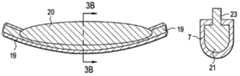
- FIG. 21shows an illustration in partial section of an embodiment of the anchoring device in the unloaded state.
- FIG. 22shows an illustration in partial section of the anchoring device according to FIG. 21 in the loaded state in the resting position.
- FIG. 23shows an illustration in partial section of the anchoring device of FIG. 21 in the loaded state during the action of a force upon the anchoring element.
- FIGS. 1 a - cthere are provided devices utilizing an internally reinforced polymeric core that is at least partially encased within at least one polymeric coating.
- a spinal fixation assembly 1comprising:
- FIG. 1 aalso shows that the rod may be bent (pre-lordosed) in order to accommodate the curvature of the spine in the region of interest.
- FIGS. 1 b - cdisclose axial cross-sections of the rod of FIG. 1 a , wherein the rod has an internally reinforced polymeric core 5 that is encased within a polymeric coating 7 .
- FIG. 1 bdiscloses a circular cross-section
- FIG. 1 cdiscloses an oval cross-section.
- Non-circular cross-sectionswill provide better stiffness in certain planes in torsion and/or flexion-extension.
- FIGS. 2 a - bthere are provided preferred embodiments of the rod utilizing a carbon fiber reinforced PEEK (CFRP) core that is at least partially encased within at least one polymeric coating, wherein the diameter and geometry of the central core and external rod profile can be designed to adjust their stiffnesses in various planes of motion.
- the corehas a non-circular axial cross-section.
- the axial cross-sectionhas a height and a width, wherein the height is greater than the width.
- FIG. 2 cdiscloses a core 11 having a semi-oval axial cross-section.
- the semi-oval shape of the corewill desirably increase the stiffness of the rod in the flexion/extension plane.
- the core 13has a frustoconical axial cross-section. It is believed that the frustoconical shape of the core will impart the desirable property of increased stiffness in a desired plane (flexion/extension shown) to the rod. In these embodiments, the shape of the coating 7 mimics the cross-section of the core.
- FIGS. 3 a - bthere are provided rods wherein the core or external rod profile can include ribs to increase support in various planes.
- FIGS. 3 a - bdisclose a rod having a pair of end portions 19 , and an intermediate section 20 therebetween, wherein the core of the intermediate section has a base section 21 and a rib 23 extending from the base section. It is believed that the rib of FIG. 3 a - b will desirably increase the stiffness of the rod in the flexion/extension plane.
- FIG. 3 balso discloses outer coating 7 .
- FIGS. 4 a - 5 dthere are provided rods wherein the number of carbon fiber layers, the percentage of carbon fiber, diameter(s), construction and planes of fiber orientation is adjusted, via various methods of manufacture, to further customize rod stiffness in varying planes.
- FIG. 4 adiscloses a rod having a pultruded core.
- Continuous carbon fiberis impregnated with PEEK and pulled through an extruder, thereby producing the pultruded core.
- Pull-off speed, fiber geometry, fiber bundle numbers and orientationare adjusted to optimize tensile, flexural and compressive endurance.
- FIG. 4 bwhich discloses only the core
- the carbon fibers 25align themselves within the core 27 along the longitudinal axis of the rod.
- FIG. 4 cshows an axial cross-section of the entire rod. It is believed that this embodiment in FIGS.
- FIG. 4 calso discloses outer coating 7 .
- FIG. 5 adiscloses a rod having a variable carbon fiber core.
- the core of this rodhas a pair of end portions 31 , and an intermediate section therebetween 35 , wherein the intermediate section has a high packing density of continuous carbon fiber and the end portions have a low packing density of continuous carbon fiber.
- the carbon fibers 25 throughout the corealign themselves along the longitudinal axis of the rod.
- FIG. 5 cdiscloses an axial cross-section of the pultruded core taken in the intermediate section of the rod
- FIG. 5 ddiscloses an axial cross-section of the pultruded core taken in an endportion of the rod. It is believed that this embodiment in FIG. 5 a - d has the advantage of providing customizable flexural and compressive stiffness at desired locations.
- FIGS. 5 c - dalso disclose outer coating 7 .
- FIG. 6 athere is provided a rod having a CFRP core having continuous fibers, wherein the core is made by filament winding.
- a continuous carbon fiber mandrelis concentrically wrapped with continuous carbon fiber that has been impregnated with base resin (PEEK).
- the core of the rodcomprises i) a continuous carbon fiber center 41 extending along the longitudinal axis of the core, and ii) a filament 43 wrapped in a helical manner around the continuous carbon fiber center, wherein the filament comprises carbon fibers loaded in a polymer matrix.
- the carbon fibers loaded in the polymer matrixare chopped.
- FIG. 6 cshows an axial cross-section of FIG. 6 a . It is believed that this embodiment in FIG. 6 a - c has the advantage of providing increased compressive and flexural stiffness for a given cross-sectional area when compared to PEEK or CFRP.
- FIG. 6 calso discloses outer coating 7 .
- a polymeric pedicle rodincluding features for insertion during minimally invasive surgery (MIS). These features can be on the outer coating 57 , although in the preferred embodiment the features are on continuous carbon fiber core, as the core provides increased strength, stiffness, and resistance to damage upon insertion.
- the rodhas a pair of end portions 51 , and an intermediate section 53 therebetween, and an MIS insertion feature including at least one notch 55 (for example, a plurality of notches) perpendicular to the longitudinal axis.
- the MIS insertion featureis a tapered end portion.
- the CFRP core of the present inventionis manufactured with the carbon fibers either in the form of chopped carbon fibers or in the form of continuous carbon fibers.
- carbon fiber segments of consistent or variable diameters and lengthsare blended into the PEEK resin formed into pedicle rods.
- This processcan include either direct machining from CFRP extruded rod stock or molded form, or net shape compression or injection molding of blended CFRP resin.
- the orientation of the fiberscan be generally aligned into the loaded direction.
- Continuous carbon fibersincrease the fabricated form stiffness in the plane of fiber orientation.
- the continuous carbon fibersare generally oriented in the axial plane of the device, thereby increasing the compressive strength of the spinal construct.
- the continuous carbon fiberscan be multiple strands, braids, bundles, or weaved forms including sheets.
- the continuous carbon fiberscan be coated and impregnated with PEEK and fabricated into pedicle rods via methods such as hot pressing, filament winding and pultrusion.
- a continuous carbon fiber mandrelis concentrically wrapped with continuous carbon fiber that has been impregnated with base resin (PEEK).
- PEEKbase resin
- Manufacturing variablessuch as wrapping geometry, fiber bundle number and orientation may be adjusted to optimize tensile, flexural and compressive endurance. Either blanks or net shape forms can be produced.
- continuous carbon fiberis impregnated with PEEK and pulled through an extruder.
- Manufacturing variablessuch as pull-off speed, fiber geometry, fiber bundle numbers and orientation are adjusted to optimize tensile, flexural and compressive endurance.
- Added fiber orientation and external rod lordotic shapecan be varied via take-off rolls or subsequent heat bending.
- any non-resorbable, biocompatible polymermay be used as the neat coating of the present invention.
- the carbon fiber/polymer matrix coreis coated with a PEEK coating.
- the polymer coatingprevents direct set screw contact upon the core, thereby minimizing carbon fiber wear in the rod during use.
- the polymer coating thicknesscan range from microns to millimeters. This thickness also provides a substrate for set screw impingement and/or compression into the rod, thereby enhancing attachment as well as providing a container to capture any debris that maybe formed at the inner boundaries of the core.
- Coating attachmentcan be increased by surface modifications to or pretreatment of the core, including surface machining, blasting, chemical/laser etching, dipping, priming, adhesive applications, and inclusion of surface features such as dovetails and undercut rings.
- the coatingis applied by hot pressing, wherein the carbon fiber core can be coated with direct compression or roll coating under thermal exposure. In some embodiments, the coating is applied by sputtering or hot spray coating, wherein a spray of molten PEEK can coat the carbon fiber core. In some embodiments, the coating is applied by overmolding, wherein the carbon fiber core is overmolded with PEEK resin with or without core centralization features. In some embodiments, the coating is applied by coextrusion, wherein a continuous carbon fiber/polymer matrix core is co-extruded with a coating of PEEK. In some embodiments, the coating is applied by inner-molding (Filled PEEK Sleeve), wherein a tubular form of PEEK is injected with CFRP or continuous carbon fiber PEEK via standard injection or Continuous Flow Molding (CFM).
- FFMContinuous Flow Molding
- radiographic markerscan be added to the rods of the present invention. This can be accomplished by press fitting, heat staking, adhesives, overmolding of radiopaque items (tantalum or titanium beads, rods, or fibers) into the ends of the rods, or metallic threads that are fabricated with or weaved within the CFRP core.
- Alternative means of providing radiopaque markersalso include printing a radiopaque medium onto a polymer surface. The polymer can be loaded with non-metallic, radiopaque fillers such as barium sulfate, calcium sulfate and zirconia.
- metallic set screwsare typically used to fix the rods of the present invention into the recess of the screws of the assembly.
- These set screwscan be fitted with a non-metallic insert or liner to avoid metal-to-polymer contact between the set screw and the rod of the present invention, hereby minimizing wear and slip potential, as well as minimizing rod damage from screw compression.
- components of the present inventionmay be made from any non-resorbable material appropriate for human surgical implantation, including but not limited to, surgically appropriate metals, and non-metallic materials, such as carbon fiber composites, polymers and ceramics.
- the spinal rodspreferably have CFRP cores and polymer coatings.
- the bone anchorsare generally made from metals and/or ceramics.
- the polymeris preferably selected from the group consisting of polyesters, (particularly aromatic esters such as polyalkylene terephthalates, polyamides; polyalkenes; poly(vinyl fluoride); PTFE; polyarylethyl ketone PAEK; and mixtures thereof.
- a ceramicis chosen as the material of construction for a component, then the ceramic is preferably selected from the group consisting of alumina, zirconia and mixtures thereof. It is preferred to select an alumina-zirconia ceramic, such as BIOLOX deltaTM, available from CeramTec of Plochingen, Germany. Depending on the material chosen, a smooth surface coating may be provided thereon to improve performance and reduce particulate wear debris.
- the bone anchorconsists essentially of a metallic material, preferably a titanium alloy or a chrome-cobalt alloy.
- the bone anchormay be coated with a wear-resistant coating, such as diamond film, in order to reduce wear.
- the rod coreis made from a composite comprising carbon fiber.
- Composites comprising carbon fiberare advantageous in that they typically have a strength and stiffness that is superior to neat polymer materials such as a polyarylethyl ketone PAEK.
- the rodis made from a polymer composite such as a PEEK-carbon fiber composite.
- the composite comprising carbon fiberfurther comprises a polymer.
- the polymeris a polyarylethyl ketone PAEK. More preferably, the PAEK is selected from the group consisting of polyetherether ketone PEEK, polyether ketone ketone PEKK and polyether ketone PEK. In preferred embodiments, the PAEK is PEEK.
- the carbon fibercomprises between 1 vol % and 60 vol % (more preferably, between 10 vol % and 50 vol %) of the composite.
- the polymer and carbon fibersare homogeneously mixed.
- the materialis a laminate.
- the carbon fiberis present as chopped state.
- the chopped carbon fibershave a median length of between 1 mm and 12 mm, more preferably between 4.5 mm and 7.5 mm.
- the carbon fiberis present as continuous strands.
- the compositecomprises:
- the compositeconsists essentially of PAEK and carbon fiber. More preferably, the composite comprises 60-80 wt % PAEK and 20-40 wt % carbon fiber. Still more preferably the composite comprises 65-75 wt % PAEK and 25-35 wt % carbon fiber.
- the preferred embodiment of the rodemploys a neat PEEK coating but alternate coatings including polyurethanes, UHMWPE, and ceramics can be utilized.
- carbon fiberis currently the preferred reinforcement material of the present invention
- other internal reinforcement materials known to industrymay also be utilized (such as glass, PLT, KLVLARTM (tradename?), clay, pararamid, self-reinforced polyphenylene, polysulfones, polyethersulfones, PMMA, DYNEEMATM, ultra high molecular weight polyethylene (UHMWPE), and talc).
- the reinforced polymeric rodis implanted in a similar manner to that known in the art of implantation of metallic rods and screw systems including open procedures and MIS insertion means.
- the mobile screwincludes a mobile bearing element disposed between the screw head and the rod, wherein the mobile element forms a ball and socket connection with the screw head.
- the mobile screwuses a resilient pressure element acting on the head, wherein upon movement of the element from a first angular position of the shank relative to said receiving part into a second angular position, the pressure element exerts a return force onto the head to urge the element towards the first angular position.
- FIGS. 8 , 19 and 20various embodiments of such a dynamic screw are disclosed herein shown in FIGS. 8 , 19 and 20 .
- Similar embodiments of the mobile bearing element forming a ball and socket bearing connection with the screw headare disclosed in US Patent Publications Nos. 2008/0161863 (Arnold I) and 2008/0161853 (Arnold II), the specifications of which are hereby incorporated by references in their entireties.
- a dynamic screw for a spine stabilization systemcomprises at least one bone anchor assembly 103 comprising a bone engaging member 105 and a receiver member 109 .
- the bone engaging membermay comprise a bone screw including a screw head retained within the receiver member and a screw shank extending from the receiver member.
- Mobile bearing element 111 disposed within the receiving memberallows the screw head to be pivotably retained thereon.
- a flexible elongated connecting member 101is connected to the receiving member.
- the elongated connecting membermay be provided as a rod spanning between two or more bone anchor assemblies.
- the elongated connecting memberis pivotably connected to the receiver member of the bone anchor assembly.
- a pivotable connection between the flexible elongated connection member and the receiver memberis provided by a ball-shaped pivot member on the rod which engages a bearing surface provided within a cavity of the receiver member.
- the pivot point for the rodmay be provided within the cavity in the receiver member.
- the rodmay define an axis wherein the axis pivots about a pivot point on the axis when the rod pivots relative to the receiver member.
- the pivot point of the rodis offset from the axis defined by the rod.
- the flexible rodmay be a fixed length or adjustable to accommodate different segmental units and patients of different sizes.
- the rodcomprises a shaft with a flexible central portion and at least one adjustable end.
- the adjustable endmay be provided by various means.
- the adjustable endmay include a post configured to slide within the shaft of the rod.
- the adjustable endis configured to threadably engage the shaft.
- the adjustable endis comprised of a shape memory alloy.
- the spine stabilization systemWhen assembled, the spine stabilization system generally comprises at least two bone anchors with a rod extending between the two bone anchors.
- each bone anchorincludes a bone screw and a receiver member configured to retain the bone screw.
- the rodextends between the two receiver members.
- the rodis fixed relative to the receiver members, the rod is adapted to bend when the receiver members move relative to one another.
- the rodis pivotably connected to both the receiver members, and the rod is adapted to extend or compress when the receiver members move relative to one another.
- one or more bone anchors of the spine stabilization systeminclude an insert in the form of a retention member that acts to lock a bearing for the bone screw within the receiver member.
- the receiver memberincludes a screw head cavity and a rod cavity with an insert positioned between the screw head cavity and the rod cavity.
- the screw head cavityis configured to receive a bearing that engages the head of the bone screw with the screw shank extending from the receiver member.
- the bone screw bearingis a split bearing.
- the insertis positioned between the rod cavity and the bearing member and is configured to secure the split bearing within the receiver member.
- the insertmay be provided to fit within a groove formed in an interior sidewall of the receiver member.
- the insertcomprises a retaining ring that secures the split bearing within the screw cavity.
- the insertis comprised of a compressible material positioned between the bearing member and the rod cavity. When the rod is positioned in the rod cavity, the insert is compressed against the bearing member, thus locking the bearing member within the screw cavity.
- the bone anchor assemblyis configured with a low profile, wherein the rod is locked within the receiver member without the use of a fixation screw.
- the bone anchor assemblyincludes a head and a screw shank extending from the head. The screw shank is pivotable with respect to the head.
- a rod cavityis formed within the head.
- the end of the rodincludes features that lock the rod within the rod cavity when the rod is inserted into the rod cavity, thus connecting the rod to the head.
- the end of the rodcomprises a plurality of fingers that may be flared to lock the rod within the rod cavity.
- the rodmay also include a plurality of teeth that grasp or mesh with the rod cavity to further secure the rod within the cavity.
- a spine stabilization systemcomprising: a) a bone engaging member; b) a receiver member pivotably connected to the bone engaging member, the receiver member including a connecting member cavity and a bearing in contact with the bone engaging member; c) a flexible, elongated connecting member extending into the connecting member cavity of the receiver member; and d) a retention member positioned between the elongated connecting member and the bearing within the receiver member, the retention member configured to secure the bearing in place within the retention member.
- the dynamic stabilization devicein particular for vertebrae, comprises a pair of mobile head polyaxial pedicle screws connected by a flexible rod disclosed herein.
- Mobile head polyaxial screwswill toggle allowing motion, while preventing torque transmission to the screw bone interface.
- the flexible rodwill be made of a material (such as a polymer such as PEEK) that is more compliant than traditional stiff metal rods in order to allow some bending, and will preferably include some internal reinforcement. Together the components will function as a complete dynamic stabilization system.
- a modular systemis also disclosed, which provides a surgical implant set containing a compliant polymer rod and a pair of mobile head polyaxial screws. Depending on the indications, the surgeon may choose to use one or both components to create a dynamic fusion or dynamic stabilization construct.
- the present inventioncontemplates the pairing of mobile head polyaxial screws with a reinforced flexible polymer rod to create a posterior dynamic stabilization (PDS) system.
- PDSposterior dynamic stabilization
- the toggle of the dynamic pedicle screwsallows for change in the interpedicular distance during flexion and extension, and the flexible polymer rod flexes to accommodate vertebral body motion.
- the dynamic polyaxial screw of the present inventionprevents torque transmission to the screw-bone interface.
- a ball-and-socket (preferably, polymeric) component within the screwallows the shank to toggle with respect to the screw head, while the flexible rod locks to the receiving part
- the flexible polymer rodis generally a flexible composite rod, and in some embodiments, is reinforced for strength, with reinforcing fibers.
- the flexible polymer rodcan be made from a number of flexible, biocompatible materials. Polymers such as PEEK, polycarbonate-urethane (PCU) and CFRP are among the preferred choices.
- the flexible polymer rodcan be made from either neat polymers or from polymers supplemented with reinforcing fibers. However, in other embodiments the flexible rod may be made of metals, such as nitinol or titanium.
- the flexible polymer rodcan be constructed with a variety of different cross-sections, which may be of constant or variable dimension.
- the reinforcement materialcan be located anywhere throughout the cross section of the flexible polymer rod to create the desired strength and flexibility. The flexibility may also vary depending on the axis of bend to provide stiffness in different ranges of motion. For example, a flexible polymer rod may be made stiffer in rotation than in flexion.
- Composite flexible polymer rods having fiber reinforcementscan be constructed in a variety of configurations to fine-tune strength and flexibility requirements of a particular device.
- the rod 113 shown in FIG. 9may be constructed of various materials, including biocompatible polymers, metals or a combination thereof.
- the geometry shown here in FIG. 9is not intended to limit the scope of the invention, but rather to show that flexible polymer rods can be created in a variety of configurations that allow bending and flexibility without fracture during a PDS device's life.
- the diameter of the central core reinforcement and the size of the reinforcement weavemay be adjusted to change the rod's performance characteristics.
- the weave featuremay also be accomplished by a waffle-like matrix or any other shape or orientation of fibers that would provide the same function without deviating from the concept.
- the weave and longitudinal fibers, although centered around the axis here in FIG. 9may also be biased towards one side of the rod.
- the rod 113 of FIG. 9comprises a polymer shell 115 typically made of PEEK) surrounding the central fiber core 117 .
- FIG. 10discloses a side view of the rod 113 of FIG. 9 , detailing the weave of longitudinal fibers 117 .
- rod 119has longitudinal fiber core 121 in the absence of a weave.
- FIGS. 12-18disclose examples of the different orientations of the reinforcement material used to create the composite rod.
- the PEEK polymer materialmay be injection molded around the reinforcement material, or a polymer may be thermoset around the reinforcement matrix. Although a round rod cross-section is shown here in these FIGS., there is no limit to the type of rod cross section which could be used.
- FIGS. 12 and 13there are provided various view of a rod 123 of the present invention having weaved fibers 125 located at an intermediate depth of the rod, thereby providing strength in flexion (tension).
- the fibersform a helical pattern, thereby forms an annular ring of fiber in cross section.
- the polymer jacket surrounding the fiber coreallows flexibility and provides a clamping surface. Therefore, the cross section of the rod displays a polymer central portion 131 , a fiber intermediate portion 133 and a polymer outer portion 135 .
- FIG. 14there is provided another embodiment of the rod of the present invention, wherein the fibers form a central braided core 137 .
- FIGS. 15 and 16there is provided another embodiment of the rod of the present invention, wherein the fibers form an annular ring 139 located just below the outer surface 141 of the rod.
- the fiber locationis driven by the desired rod characteristics.
- FIGS. 17 and 18there is provided another embodiment of the rod of the present invention, wherein the rod has a plane 143 of fibers oriented along the center of the rod to provide greater stiffness in response to certain motions.
- this rodmay allow more movement in flexion/extension, but less motion in lateral bending.
- the two images provided in FIGS. 19 and 20show translucency to better describe their functions:
- the bulk rod material 151is semi-transparent to allow visualization of the internal reinforcement fibers, which provide strength.
- the top dynamic screw 153shows translucency to allow better description of the internal function.
- the polymer insert bearing 155surrounds the shank screw head 157 providing a mobile surface for the motion to occur.
- the rodlocks to the titanium head.
- the rod 151 and screw 153function together to allow posterior dynamic stabilization.
- the flexible polymer rod 151bends as the screw head toggles, allowing for change in interpedicular distance.
- the flexibility of the PDS systemcan be tweaked by changing the rod design and the range of motion within the dynamic polyaxial screw.
- the PDS system of the present inventionimproves torsional stability, as the mobile screw heads may only allow uniplanar motion/toggle.
- the mobile head screwsalso provide reduced screw-bone interface stresses as torque on the rod is not transferred to the screw shank.
- the mobile head component of the present inventionis substantially similar to the resilient mobile head component described in US Published Patent Application No. 2004/0225289 (Biedermann), the specification of which is incorporated by reference in its entirety.
- the flexible rods 300 of the present inventionare combined with a pair of dynamic anchoring devices 201 .
- each of these dynamic anchoring devicescomprises i) a shank 203 for anchoring into a bone or a vertebra, ii) a head connected to the shank, iii) a receiving part 205 for the head and iv) a resilient (preferably, elastomeric) pressure element 220 acting on the head.
- the pressure elementis formed and located in such a way that, upon a movement of the element from a first angular position of the shank relative to the receiving part into a second angular position, it exerts a return force on the head.
- the present inventionincludes a dynamic stabilization device, in particular for vertebrae. In such a stabilization device, the flexible rod is connected to two anchoring devices. At least one of the anchoring devices is constructed as a dynamic anchoring element.
- the present inventionprovides an anchoring device comprising an element having a shank for anchoring in a bone or a vertebra and a head connected to the shank, a receiving part for receiving the head, and a pressure element acting on the head, wherein the pressure element is resilient so that upon a movement of the element from a first angular position of the shank relative to said receiving part into a second angular position the pressure element exerts a return force onto the head to urge the element towards the first angular position.
- the resilient pressure elementacts on the side of the head facing away from the shank and is formed of an elastomer.
- the resilient pressure elementcomprises at least one spring element.
- the devicemay also include a rigid element acting on the pressure element on a side of the pressure element opposite to the head.
- the pressure elementis substantially cylindrical and comprises a first section which is resilient and a second section which is rigid and which is located on a side opposite to the head; Typically, this second section comprises a U-shaped recess to receive a rod to be received in the receiving part, the recess forming two free legs and wherein a depth of the recess is greater than the diameter of the rod;
- the first section and the second section of the pressure elementare separate parts.
- the pressure elementis formed by an insert made of an elastomer and has a support surface for the head to rest against.
- the pressure elementis pre-compressed by the rod when the rod lies on the bottom of the U-shaped recess.
- the pressure elementis arranged in the receiving part under pre-stress.
- this second elastic pressure elementencompassing the head in a ring shape.
- This second pressure elementmay be shaped as O-ring or as a molded ring.
- the headcomprises a flat surface on the side facing away from the shank and the resilient pressure element comprises a flat surface cooperating therewith.
- the headmay comprise a spherical segment-shaped section adjacent to the shank and a collar on the side facing away from the shank.
- the head and the shankare separate parts, wherein the head has a central axis and the shank is connectable to the head at a predetermined angle a to the central axis.
- the receiving partcomprises a support surface to support the head, the support surface and/or the head being polished or coated to reduce friction.
- the receiving partcomprises a U-shaped recess for inserting a rod and the pressure element is arranged between the head and the rod when the rod is inserted into the receiving part.
- the inventionalso provides a dynamic stabilization device for bones, in particular for vertebrae, having at least two anchoring devices connected to a flexible polymer rod, wherein one of the anchoring devices is formed as the anchoring device described above.
- the inventionprovides a method for using the dynamic anchoring device and a method for stabilizing bones, in particular for stabilizing vertebrae, wherein the anchoring device is formed as the anchoring device described above.
- the dynamic anchoring element 201is formed as a polyaxial screw. It comprises a screw element 202 with a threaded shank part 203 and a head 204 formed in one piece therewith and a receiving part 205 .
- the head 204is substantially formed in the shape of a segment of a sphere and has on its end opposite to the shank part 203 a widened edge or collar 206 , so that a flat front face 207 is formed which has a diameter which is larger than the diameter of the spherical segment-shaped section of the head.
- a recess for bringing into engagement with a screwing-in toolis further formed in the front face 207 .
- the receiving part 205is substantially formed cylindrically symmetric and has on one of its ends a coaxial first bore 210 the diameter of which is larger than that of the threaded section of the shank 203 and smaller than the spherical diameter of the spherical segment-shaped section of the head 204 . It further has a coaxial second bore 211 which is open at the end opposite the first bore 210 and the diameter of which is large enough for the screw element 202 to be inserted through the open end with its threaded section through the first bore 210 and with the spherical segment-shaped section of the head 204 to the bottom of the second bore.
- a section 212is provided, shaped like a segment of a hollow sphere, the radius of which is substantially identical to the radius of the section of the spherical segment-shaped head 204 .
- the receiving partfurther has a U-shaped recess 213 , extending from the open end towards the first bore 210 , the bottom of which is directed towards the first bore 210 and by which two open legs 214 are formed, only one of which is illustrated in the figures.
- An inner thread 215is formed in the receiving part adjacent to the open end of the legs 214 .
- the width of the U-shaped recess 213is minimally larger than the diameter of a rod 300 to be received therein which connects several such polyaxial screws.
- the depth of the U-shaped recessis dimensioned in such a way that when the rod is inserted a fixing screw 216 can be screwed in between the legs.
- the section 212 of the receiving partwhich is shaped like a segment of a hollow sphere is preferably polished smooth or coated with a material which increases the sliding capacity, so the head 204 can easily be swiveled in the section 212 of the receiving part.
- the head 204is polished smooth or coated.
- the pressure element 220is formed in the shape of a cylinder and has a diameter which is smaller than the inner diameter of the second bore 211 of the receiving part and which is preferably identical to the diameter of the front face 207 of the head.
- the axial length of the pressure element 220is slightly larger than or identical to the distance between the front face 207 of the head 204 and the bottom of the U-shaped recess 213 in the inserted state.
- the pressure elementis resilient, in the illustrated embodiment it is formed from an elastomer, e.g., from polyurethanes or polysiloxanes. However, any suitable biocompatible material can be used.
- a cap 221which covers the pressure element on the side facing the rod and which is constructed from an inflexible material, for example a synthetic material or a body-compatible metal.
- the outer diameter of the cap 221is dimensioned in such a way that the cap is displaceable by sliding in the second bore of the receiving part and the inner diameter of the cap substantially corresponds to the outer diameter of the pressure element 220 when this is in an unloaded state.
- the capoverlaps the pressure element to such an extent that the pressure element is able to expand in the radial direction when put under load.
- FIG. 21shows the unloaded state in which the screw element 202 , the pressure element 220 and the cap 221 are inserted into the receiving part and the rod 300 is placed into the U-shaped recess 213 , but the inner screw has not yet been screwed down.
- the side 222 of the cap 221 facing away from the pressure element 213is at a slightly higher position than the bottom of the U-shaped recess 213 , so that the rod rests with its lower side on the surface 222 of the cap and thus a gap 213 is formed between the lower side of the rod and the bottom of the U-shaped recess 213 .
- the screw element 202is inserted into the receiving part 205 from the open end thereof until the head rests against the section 212 of the receiving part shaped like a segment of a hollow sphere.
- the screw elementis then screwed into the vertebra.
- the pressure element 220 together with the cap 221 placed thereonis inserted into the receiving part, the receiving part is aligned and the rod inserted.
- the inner screw 216is screwed into the receiving part.
- the inner screwis screwed in until it presses the rod against the bottom of the U-shaped recess and thus fixes the rod.
- the rodpresses on the cap 221 , which serves for even distribution of the force of pressure exerted by the rod on to the entire surface of the pressure element. Due to the elasticity of the pressure element it is pre-compressed via the force exerted by the rod.
- the pressure elementtakes on a shape curved outwards in the radial direction, shown in FIG. 22 .
- the pressure element 220is under bias in respect of the screw head 204 and due to the return force it presses with its lower side evenly on the front face 207 of the head. In this way, the head is pressed against the section 212 of the receiving part.
- the screw element 202 screwed into the vertebral bodyis moved out of its resting position by a self-movement of the vertebral column.
- the vertebramoves towards the rod at an angle of 90° to the rod axis there is uniform compression of the pressure element and the angle of the shank relative to the receiving part does not change.
- the vertebramoves at an angle other than 90° to the rod axis, as shown in FIG. 23 , there is a swiveling of the head, which easily slides in the section 212 of the receiving part.
- the front face 207 of the screw headexerts a compression force on to the pressure element on one side which compresses it on one side near the edge.
- the pressure element standing under pre-stressexpands owing to the relief of pressure.
- the pressure elementalways remains in contact with the screw head.
- the compressioneffects a return force onto the screw head. In this way, a movement of the vertebra back into its original position in which it has been placed by the surgeon is supported.
- elastomer materialfor the pressure element with a desired compressibility a limitation of motion of the vertebra can be adjusted. If the material is only slightly compressible, the device allows only a small deflection out of the resting position. If the material properties are changed, larger swivel ranges are possible. Those skilled in the art can readily substitute materials using routine experimentation.
- Body-compatible elastomercan be used as elastomer material, e.g., polyurethanes or polysiloxanes.
- the swivel rangecan also or additionally be set by the selection of the diameter of the collar 206 of the screw head relative to the diameter of the second bore 211 of the receiving part.
Landscapes
- Health & Medical Sciences (AREA)
- Orthopedic Medicine & Surgery (AREA)
- Life Sciences & Earth Sciences (AREA)
- Neurology (AREA)
- Surgery (AREA)
- Heart & Thoracic Surgery (AREA)
- Engineering & Computer Science (AREA)
- Biomedical Technology (AREA)
- Nuclear Medicine, Radiotherapy & Molecular Imaging (AREA)
- Medical Informatics (AREA)
- Molecular Biology (AREA)
- Animal Behavior & Ethology (AREA)
- General Health & Medical Sciences (AREA)
- Public Health (AREA)
- Veterinary Medicine (AREA)
- Surgical Instruments (AREA)
- Prostheses (AREA)
- Materials For Medical Uses (AREA)
Abstract
Description
- a. a spinal pedicle rod comprising an internally reinforced polymeric core that is at least partially encased within at least one polymeric coating, and
- b. a bone anchor having a recess for accepting the rod,
wherein the rod is fixed in the recess of the bone anchor.
- disclose specific PEEK-coated CFRP pedicle rod designs that enhance fatigue endurance and minimize wear at the set screw/rod interface;
- employ specific manufacturing methods to orient the reinforcement fibers in desired directions and coat the core with neat PEEK;
- disclose embodiments that utilize continuous fiber internal reinforcement;
- disclose specific geometries of fiber orientation that balance stiffness and strength in various planes of motion and fatigue endurance; and
- utilize the CFRP core for MIS inserter attachment.
- a) a spinal pedicle rod3 comprising an internally reinforced
polymeric core 5 that is at least partially encased within at least onepolymeric coating 7, and - b) a
bone anchor 8 having a recess9 for accepting the rod,
wherein the rod is fixed in the recess of the bone anchor.
- a) a spinal pedicle rod3 comprising an internally reinforced
- a) 40-99% (more preferably, 60-80 vol %) polyarylethyl ketone PAEK, and
- b) 1-60% (more preferably, 20-40 vol %) carbon fiber, wherein the polyarylethyl ketone PAEK is selected from the group consisting of polyetherether ketone PEEK, polyether ketone ketone PEKK and polyether ketone PEK.
Claims (8)
Priority Applications (6)
| Application Number | Priority Date | Filing Date | Title |
|---|---|---|---|
| US12/234,091US9232968B2 (en) | 2007-12-19 | 2008-09-19 | Polymeric pedicle rods and methods of manufacturing |
| JP2010539701AJP2011508623A (en) | 2007-12-19 | 2008-12-16 | Polymer pedicle rod and manufacturing method |
| EP08868340AEP2227158A4 (en) | 2007-12-19 | 2008-12-16 | Polymeric pedicle rods and methods of manufacturing |
| CA2709942ACA2709942A1 (en) | 2007-12-19 | 2008-12-16 | Polymeric pedicle rods and methods of manufacturing |
| AU2008343331AAU2008343331B2 (en) | 2007-12-19 | 2008-12-16 | Polymeric pedicle rods and methods of manufacturing |
| PCT/US2008/086979WO2009085749A2 (en) | 2007-12-19 | 2008-12-16 | Polymeric pedicle rods and methods of manufacturing |
Applications Claiming Priority (2)
| Application Number | Priority Date | Filing Date | Title |
|---|---|---|---|
| US1485107P | 2007-12-19 | 2007-12-19 | |
| US12/234,091US9232968B2 (en) | 2007-12-19 | 2008-09-19 | Polymeric pedicle rods and methods of manufacturing |
Publications (2)
| Publication Number | Publication Date |
|---|---|
| US20090163955A1 US20090163955A1 (en) | 2009-06-25 |
| US9232968B2true US9232968B2 (en) | 2016-01-12 |
Family
ID=40789534
Family Applications (1)
| Application Number | Title | Priority Date | Filing Date |
|---|---|---|---|
| US12/234,091Expired - Fee RelatedUS9232968B2 (en) | 2007-12-19 | 2008-09-19 | Polymeric pedicle rods and methods of manufacturing |
Country Status (6)
| Country | Link |
|---|---|
| US (1) | US9232968B2 (en) |
| EP (1) | EP2227158A4 (en) |
| JP (1) | JP2011508623A (en) |
| AU (1) | AU2008343331B2 (en) |
| CA (1) | CA2709942A1 (en) |
| WO (1) | WO2009085749A2 (en) |
Cited By (17)
| Publication number | Priority date | Publication date | Assignee | Title |
|---|---|---|---|---|
| US11109802B2 (en) | 2016-01-11 | 2021-09-07 | Kambiz Behzadi | Invasive sense measurement in prosthesis installation and bone preparation |
| US11116639B2 (en) | 2016-04-07 | 2021-09-14 | Kambiz Behzadi | Mechanical assembly including exterior surface preparation |
| US11234840B2 (en) | 2016-01-11 | 2022-02-01 | Kambiz Behzadi | Bone preparation apparatus and method |
| US11241248B2 (en) | 2016-01-11 | 2022-02-08 | Kambiz Behzadi | Bone preparation apparatus and method |
| US11298102B2 (en) | 2016-01-11 | 2022-04-12 | Kambiz Behzadi | Quantitative assessment of prosthesis press-fit fixation |
| US11331069B2 (en) | 2016-01-11 | 2022-05-17 | Kambiz Behzadi | Invasive sense measurement in prosthesis installation |
| US11375975B2 (en) | 2016-01-11 | 2022-07-05 | Kambiz Behzadi | Quantitative assessment of implant installation |
| US11399946B2 (en) | 2016-01-11 | 2022-08-02 | Kambiz Behzadi | Prosthesis installation and assembly |
| US11406504B2 (en) | 2016-06-12 | 2022-08-09 | Kambiz Behzadi | Mechanical assembly including exterior surface preparation |
| US11458028B2 (en) | 2016-01-11 | 2022-10-04 | Kambiz Behzadi | Prosthesis installation and assembly |
| US11534314B2 (en) | 2016-01-11 | 2022-12-27 | Kambiz Behzadi | Quantitative assessment of prosthesis press-fit fixation |
| US11583318B2 (en) | 2018-12-21 | 2023-02-21 | Paradigm Spine, Llc | Modular spine stabilization system and associated instruments |
| US11717310B2 (en) | 2016-01-11 | 2023-08-08 | Kambiz Behzadi | Bone preparation apparatus and method |
| US11751807B2 (en) | 2016-01-11 | 2023-09-12 | Kambiz Behzadi | Invasive sense measurement in prosthesis installation and bone preparation |
| US11969336B2 (en) | 2018-10-08 | 2024-04-30 | Kambiz Behzadi | Connective tissue grafting |
| US11974877B2 (en) | 2016-01-11 | 2024-05-07 | Kambiz Behzadi | Quantitative assessment of implant bone preparation |
| US12193951B2 (en) | 2016-01-11 | 2025-01-14 | Kambiz Behzadi | Quantitative assessment of prosthesis press-fit fixation |
Families Citing this family (114)
| Publication number | Priority date | Publication date | Assignee | Title |
|---|---|---|---|---|
| US7833250B2 (en) | 2004-11-10 | 2010-11-16 | Jackson Roger P | Polyaxial bone screw with helically wound capture connection |
| US8292926B2 (en) | 2005-09-30 | 2012-10-23 | Jackson Roger P | Dynamic stabilization connecting member with elastic core and outer sleeve |
| US8353932B2 (en) | 2005-09-30 | 2013-01-15 | Jackson Roger P | Polyaxial bone anchor assembly with one-piece closure, pressure insert and plastic elongate member |
| US10729469B2 (en) | 2006-01-09 | 2020-08-04 | Roger P. Jackson | Flexible spinal stabilization assembly with spacer having off-axis core member |
| US10258382B2 (en) | 2007-01-18 | 2019-04-16 | Roger P. Jackson | Rod-cord dynamic connection assemblies with slidable bone anchor attachment members along the cord |
| US7862587B2 (en) | 2004-02-27 | 2011-01-04 | Jackson Roger P | Dynamic stabilization assemblies, tool set and method |
| WO2006052796A2 (en) | 2004-11-10 | 2006-05-18 | Jackson Roger P | Helical guide and advancement flange with break-off extensions |
| US8876868B2 (en) | 2002-09-06 | 2014-11-04 | Roger P. Jackson | Helical guide and advancement flange with radially loaded lip |
| US7621918B2 (en) | 2004-11-23 | 2009-11-24 | Jackson Roger P | Spinal fixation tool set and method |
| US7377923B2 (en) | 2003-05-22 | 2008-05-27 | Alphatec Spine, Inc. | Variable angle spinal screw assembly |
| US8398682B2 (en) | 2003-06-18 | 2013-03-19 | Roger P. Jackson | Polyaxial bone screw assembly |
| US7776067B2 (en) | 2005-05-27 | 2010-08-17 | Jackson Roger P | Polyaxial bone screw with shank articulation pressure insert and method |
| US8092500B2 (en) | 2007-05-01 | 2012-01-10 | Jackson Roger P | Dynamic stabilization connecting member with floating core, compression spacer and over-mold |
| US8926670B2 (en) | 2003-06-18 | 2015-01-06 | Roger P. Jackson | Polyaxial bone screw assembly |
| US8137386B2 (en) | 2003-08-28 | 2012-03-20 | Jackson Roger P | Polyaxial bone screw apparatus |
| US8377102B2 (en) | 2003-06-18 | 2013-02-19 | Roger P. Jackson | Polyaxial bone anchor with spline capture connection and lower pressure insert |
| US7766915B2 (en) | 2004-02-27 | 2010-08-03 | Jackson Roger P | Dynamic fixation assemblies with inner core and outer coil-like member |
| US7179261B2 (en) | 2003-12-16 | 2007-02-20 | Depuy Spine, Inc. | Percutaneous access devices and bone anchor assemblies |
| US7527638B2 (en) | 2003-12-16 | 2009-05-05 | Depuy Spine, Inc. | Methods and devices for minimally invasive spinal fixation element placement |
| US11419642B2 (en) | 2003-12-16 | 2022-08-23 | Medos International Sarl | Percutaneous access devices and bone anchor assemblies |
| US8152810B2 (en) | 2004-11-23 | 2012-04-10 | Jackson Roger P | Spinal fixation tool set and method |
| JP2007525274A (en) | 2004-02-27 | 2007-09-06 | ロジャー・ピー・ジャクソン | Orthopedic implant rod reduction instrument set and method |
| US11241261B2 (en) | 2005-09-30 | 2022-02-08 | Roger P Jackson | Apparatus and method for soft spinal stabilization using a tensionable cord and releasable end structure |
| US7160300B2 (en) | 2004-02-27 | 2007-01-09 | Jackson Roger P | Orthopedic implant rod reduction tool set and method |
| US7651502B2 (en) | 2004-09-24 | 2010-01-26 | Jackson Roger P | Spinal fixation tool set and method for rod reduction and fastener insertion |
| US8926672B2 (en) | 2004-11-10 | 2015-01-06 | Roger P. Jackson | Splay control closure for open bone anchor |
| US9216041B2 (en) | 2009-06-15 | 2015-12-22 | Roger P. Jackson | Spinal connecting members with tensioned cords and rigid sleeves for engaging compression inserts |
| US9980753B2 (en) | 2009-06-15 | 2018-05-29 | Roger P Jackson | pivotal anchor with snap-in-place insert having rotation blocking extensions |
| US8308782B2 (en) | 2004-11-23 | 2012-11-13 | Jackson Roger P | Bone anchors with longitudinal connecting member engaging inserts and closures for fixation and optional angulation |
| US9168069B2 (en) | 2009-06-15 | 2015-10-27 | Roger P. Jackson | Polyaxial bone anchor with pop-on shank and winged insert with lower skirt for engaging a friction fit retainer |
| US8444681B2 (en) | 2009-06-15 | 2013-05-21 | Roger P. Jackson | Polyaxial bone anchor with pop-on shank, friction fit retainer and winged insert |
| WO2006057837A1 (en) | 2004-11-23 | 2006-06-01 | Jackson Roger P | Spinal fixation tool attachment structure |
| US10076361B2 (en) | 2005-02-22 | 2018-09-18 | Roger P. Jackson | Polyaxial bone screw with spherical capture, compression and alignment and retention structures |
| US7901437B2 (en) | 2007-01-26 | 2011-03-08 | Jackson Roger P | Dynamic stabilization member with molded connection |
| US8105368B2 (en) | 2005-09-30 | 2012-01-31 | Jackson Roger P | Dynamic stabilization connecting member with slitted core and outer sleeve |
| US7815663B2 (en) | 2006-01-27 | 2010-10-19 | Warsaw Orthopedic, Inc. | Vertebral rods and methods of use |
| CA2670988C (en) | 2006-12-08 | 2014-03-25 | Roger P. Jackson | Tool system for dynamic spinal implants |
| US8366745B2 (en) | 2007-05-01 | 2013-02-05 | Jackson Roger P | Dynamic stabilization assembly having pre-compressed spacers with differential displacements |
| US8475498B2 (en) | 2007-01-18 | 2013-07-02 | Roger P. Jackson | Dynamic stabilization connecting member with cord connection |
| US10792074B2 (en) | 2007-01-22 | 2020-10-06 | Roger P. Jackson | Pivotal bone anchor assemly with twist-in-place friction fit insert |
| EP1972289B1 (en)* | 2007-03-23 | 2018-10-17 | coLigne AG | Elongated stabilization member and bone anchor useful in bone and especially spinal repair processes |
| US8979904B2 (en) | 2007-05-01 | 2015-03-17 | Roger P Jackson | Connecting member with tensioned cord, low profile rigid sleeve and spacer with torsion control |
| US10383660B2 (en) | 2007-05-01 | 2019-08-20 | Roger P. Jackson | Soft stabilization assemblies with pretensioned cords |
| US20110172708A1 (en)* | 2007-06-22 | 2011-07-14 | Simpirica Spine, Inc. | Methods and systems for increasing the bending stiffness of a spinal segment with elongation limit |
| US9439681B2 (en) | 2007-07-20 | 2016-09-13 | DePuy Synthes Products, Inc. | Polyaxial bone fixation element |
| US8366746B2 (en)* | 2008-01-03 | 2013-02-05 | Kiester P Douglas | Spine reconstruction rod extender |
| US20090234388A1 (en)* | 2008-03-15 | 2009-09-17 | Warsaw Orthopedic, Inc. | Spinal Stabilization Connecting Element and System |
| US20090259257A1 (en)* | 2008-04-15 | 2009-10-15 | Warsaw Orthopedic, Inc. | Pedicule-Based Motion- Preserving Device |
| AU2010260521C1 (en) | 2008-08-01 | 2013-08-01 | Roger P. Jackson | Longitudinal connecting member with sleeved tensioned cords |
| US8979905B2 (en)* | 2008-09-10 | 2015-03-17 | Life Spine, Inc. | Spinal rod |
| US9408649B2 (en) | 2008-09-11 | 2016-08-09 | Innovasis, Inc. | Radiolucent screw with radiopaque marker |
| JP5815407B2 (en) | 2008-09-12 | 2015-11-17 | ジンテス ゲゼルシャフト ミット ベシュレンクテル ハフツング | Spinal stabilization and guided fixation system |
| US20100117310A1 (en) | 2008-11-07 | 2010-05-13 | Saint-Gobain Performance Plastics Corporation | Large diameter thermoplastic seal |
| JP5345696B2 (en)* | 2008-11-07 | 2013-11-20 | サン−ゴバン パフォーマンス プラスティックス コーポレイション | Method for forming a large diameter thermoplastic seal |
| US20100222820A1 (en)* | 2009-02-27 | 2010-09-02 | Warsaw Orthopedic, Inc. | Vertebral rod system and methods of use |
| US8118840B2 (en) | 2009-02-27 | 2012-02-21 | Warsaw Orthopedic, Inc. | Vertebral rod and related method of manufacture |
| KR20120013312A (en) | 2009-04-15 | 2012-02-14 | 신세스 게엠바하 | Orthodontic Connectors for Spinal Structures |
| US9668771B2 (en) | 2009-06-15 | 2017-06-06 | Roger P Jackson | Soft stabilization assemblies with off-set connector |
| US11229457B2 (en) | 2009-06-15 | 2022-01-25 | Roger P. Jackson | Pivotal bone anchor assembly with insert tool deployment |
| CN103826560A (en) | 2009-06-15 | 2014-05-28 | 罗杰.P.杰克逊 | Polyaxial Bone Anchor with Socket Stem and Winged Inserts with Friction Fit Compression Collars |
| US8998959B2 (en) | 2009-06-15 | 2015-04-07 | Roger P Jackson | Polyaxial bone anchors with pop-on shank, fully constrained friction fit retainer and lock and release insert |
| CA2764841A1 (en)* | 2009-06-17 | 2010-12-23 | Synthes Usa, Llc | Revision connector for spinal constructs |
| US9320543B2 (en) | 2009-06-25 | 2016-04-26 | DePuy Synthes Products, Inc. | Posterior dynamic stabilization device having a mobile anchor |
| CA2767274C (en)* | 2009-07-16 | 2017-11-28 | Spinesave Ag | Anchorage arrangement for a connecting rod for the stabilization of the spine |
| US9433439B2 (en)* | 2009-09-10 | 2016-09-06 | Innovasis, Inc. | Radiolucent stabilizing rod with radiopaque marker |
| US9011494B2 (en) | 2009-09-24 | 2015-04-21 | Warsaw Orthopedic, Inc. | Composite vertebral rod system and methods of use |
| EP2485654B1 (en) | 2009-10-05 | 2021-05-05 | Jackson P. Roger | Polyaxial bone anchor with non-pivotable retainer and pop-on shank, some with friction fit |
| US20110106179A1 (en)* | 2009-10-30 | 2011-05-05 | Warsaw Orthopedic, Inc. | Set Screw Having Variable Pitch Thread for Use With Spinal Implant Systems |
| US20110106162A1 (en)* | 2009-10-30 | 2011-05-05 | Warsaw Orthopedic, Inc. | Composite Connecting Elements for Spinal Stabilization Systems |
| US20110152937A1 (en)* | 2009-12-22 | 2011-06-23 | Warsaw Orthopedic, Inc. | Surgical Implants for Selectively Controlling Spinal Motion Segments |
| US20110218574A1 (en)* | 2010-03-03 | 2011-09-08 | Warsaw Orthopedic, Inc. | Dynamic vertebral construct |
| US20120330361A1 (en)* | 2010-03-10 | 2012-12-27 | Reuven Gepstein | Spinal implantable devices made of carbon composite materials and use thereof |
| US20110257687A1 (en)* | 2010-04-19 | 2011-10-20 | Warsaw Orthopedic, Inc. | Load sharing bone fastener and methods of use |
| US12383311B2 (en) | 2010-05-14 | 2025-08-12 | Roger P. Jackson | Pivotal bone anchor assembly and method for use thereof |
| US9113960B2 (en)* | 2010-06-08 | 2015-08-25 | Globus Medical, Inc. | Conforming bone stabilization receiver |
| US20120029564A1 (en)* | 2010-07-29 | 2012-02-02 | Warsaw Orthopedic, Inc. | Composite Rod for Spinal Implant Systems With Higher Modulus Core and Lower Modulus Polymeric Sleeve |
| AU2011299558A1 (en) | 2010-09-08 | 2013-05-02 | Roger P. Jackson | Dynamic stabilization members with elastic and inelastic sections |
| US20120109207A1 (en)* | 2010-10-29 | 2012-05-03 | Warsaw Orthopedic, Inc. | Enhanced Interfacial Conformance for a Composite Rod for Spinal Implant Systems with Higher Modulus Core and Lower Modulus Polymeric Sleeve |
| AU2011324058A1 (en) | 2010-11-02 | 2013-06-20 | Roger P. Jackson | Polyaxial bone anchor with pop-on shank and pivotable retainer |
| JP5865479B2 (en) | 2011-03-24 | 2016-02-17 | ロジャー・ピー・ジャクソン | Multiaxial bone anchor with compound joint and pop-mounted shank |
| US8882806B2 (en) | 2011-04-25 | 2014-11-11 | Said ELSHIHABI | Spine stabilization system with self-cutting rod |
| US8911479B2 (en) | 2012-01-10 | 2014-12-16 | Roger P. Jackson | Multi-start closures for open implants |
| US8952105B2 (en)* | 2012-05-23 | 2015-02-10 | Baker Hughes Incorporated | Variable TG article, method of making, and use of same |
| JP2015520052A (en) | 2012-05-23 | 2015-07-16 | サン−ゴバン パフォーマンス プラスティックス コーポレイション | Method for forming large-diameter thermoplastic seals |
| EP2877109A4 (en)* | 2012-07-24 | 2016-03-23 | Carbofix In Orthopedics Llc | Spine system and kit |
| US8911478B2 (en) | 2012-11-21 | 2014-12-16 | Roger P. Jackson | Splay control closure for open bone anchor |
| EP2765163A1 (en)* | 2013-02-12 | 2014-08-13 | Solvay Specialty Polymers USA, LLC. | Mobile electronic device |
| EP2765317A1 (en)* | 2013-02-12 | 2014-08-13 | Solvay Specialty Polymers USA, LLC. | Improved fasteners |
| US20150306279A1 (en)* | 2012-12-20 | 2015-10-29 | Solvay Specialty Polymers Usa, Llc | Prosthetic device |
| US10058354B2 (en) | 2013-01-28 | 2018-08-28 | Roger P. Jackson | Pivotal bone anchor assembly with frictional shank head seating surfaces |
| US8852239B2 (en) | 2013-02-15 | 2014-10-07 | Roger P Jackson | Sagittal angle screw with integral shank and receiver |
| US9918746B2 (en) | 2013-09-01 | 2018-03-20 | Carbofix In Orthopedics Llc | Composite material spinal implant |
| US9566092B2 (en) | 2013-10-29 | 2017-02-14 | Roger P. Jackson | Cervical bone anchor with collet retainer and outer locking sleeve |
| CN103622738B (en)* | 2013-11-28 | 2016-01-06 | 浙江康慈医疗科技有限公司 | A kind of internal fixation of spine non-fused Dynamic link library rod |
| US9717533B2 (en) | 2013-12-12 | 2017-08-01 | Roger P. Jackson | Bone anchor closure pivot-splay control flange form guide and advancement structure |
| US9451993B2 (en) | 2014-01-09 | 2016-09-27 | Roger P. Jackson | Bi-radial pop-on cervical bone anchor |
| US9597119B2 (en) | 2014-06-04 | 2017-03-21 | Roger P. Jackson | Polyaxial bone anchor with polymer sleeve |
| US10064658B2 (en) | 2014-06-04 | 2018-09-04 | Roger P. Jackson | Polyaxial bone anchor with insert guides |
| EP3188678A1 (en)* | 2014-09-01 | 2017-07-12 | Carbofix In Orthopedics LLC | Composite material spinal implant |
| DE102015114270A1 (en)* | 2015-08-27 | 2017-03-02 | Illinois Tool Works Inc. | Injection molding component, joint, injection molding apparatus and method for producing an injection-molded component |
| US10448983B2 (en) | 2015-12-07 | 2019-10-22 | Carbofix In Orthopedics Llc | Core and shell coupling of a composite material bone implant |
| US11534207B2 (en)* | 2019-02-11 | 2022-12-27 | Next Orthosurgical, Inc. | Corrective angle pedicle screw technology |
| US20220160400A1 (en)* | 2019-03-12 | 2022-05-26 | Carbofix Spine Inc. | Composite material spinal implant |
| US12215565B2 (en) | 2019-06-14 | 2025-02-04 | Nine Downhole Technologies, Llc | Compact downhole tool |
| US20250146382A1 (en)* | 2019-06-14 | 2025-05-08 | Nine Downhole Technologies, Llc | Compact downhole tool |
| US11365600B2 (en) | 2019-06-14 | 2022-06-21 | Nine Downhole Technologies, Llc | Compact downhole tool |
| JP7446965B2 (en)* | 2020-09-29 | 2024-03-11 | グローブライド株式会社 | Spinal fixation rod |
| JP7432538B2 (en) | 2021-01-05 | 2024-02-16 | グローブライド株式会社 | Rod for spinal fixation device and spinal fixation device equipped with the same |
| JP7432541B2 (en)* | 2021-01-25 | 2024-02-16 | グローブライド株式会社 | Rod for spinal fixation device and spinal fixation device equipped with the same |
| CN113209389B (en)* | 2021-03-18 | 2023-07-18 | 龙甲(上海)实业有限公司 | Medical orthopaedics bone nail and preparation method thereof |
| JP7626681B2 (en) | 2021-08-05 | 2025-02-04 | グローブライド株式会社 | Spinal Fixation Rods |
| US20230225765A1 (en)* | 2022-01-18 | 2023-07-20 | Medos International Sarl | Spinal fixation rod having a core and an outer layer |
| JP2024142240A (en) | 2023-03-29 | 2024-10-10 | グローブライド株式会社 | Rods for spinal fixation devices |
| JP2024145952A (en)* | 2023-03-31 | 2024-10-15 | グローブライド株式会社 | Rod for spinal fixation device that is less likely to break into fragments |
Citations (263)
| Publication number | Priority date | Publication date | Assignee | Title |
|---|---|---|---|---|
| US3992725A (en) | 1973-11-16 | 1976-11-23 | Homsy Charles A | Implantable material and appliances and method of stabilizing body implants |
| EP0046518B1 (en) | 1980-08-26 | 1983-07-13 | Intermedicat GmbH | Package for surgical suture |
| US4512038A (en) | 1979-04-27 | 1985-04-23 | University Of Medicine And Dentistry Of New Jersey | Bio-absorbable composite tissue scaffold |
| US4648388A (en) | 1985-11-01 | 1987-03-10 | Acromed Corporation | Apparatus and method for maintaining vertebrae in a desired relationship |
| US4743260A (en) | 1985-06-10 | 1988-05-10 | Burton Charles V | Method for a flexible stabilization system for a vertebral column |
| US4854304A (en) | 1987-03-19 | 1989-08-08 | Oscobal Ag | Implant for the operative correction of spinal deformity |
| US5002542A (en) | 1989-10-30 | 1991-03-26 | Synthes U.S.A. | Pedicle screw clamp |
| US5034011A (en) | 1990-08-09 | 1991-07-23 | Advanced Spine Fixation Systems Incorporated | Segmental instrumentation of the posterior spine |
| US5092866A (en) | 1989-02-03 | 1992-03-03 | Breard Francis H | Flexible inter-vertebral stabilizer as well as process and apparatus for determining or verifying its tension before installation on the spinal column |
| US5180393A (en) | 1990-09-21 | 1993-01-19 | Polyclinique De Bourgogne & Les Hortensiad | Artificial ligament for the spine |
| US5181930A (en) | 1991-04-10 | 1993-01-26 | Pfizer Hospital Products Group, Inc. | Composite orthopedic implant |
| US5207678A (en) | 1989-07-20 | 1993-05-04 | Prufer | Pedicle screw and receiver member therefore |
| US5217497A (en) | 1990-07-04 | 1993-06-08 | Mehdian Seyed M H | Apparatus for use in the treatment of spinal disorders |
| US5217461A (en) | 1992-02-20 | 1993-06-08 | Acromed Corporation | Apparatus for maintaining vertebrae in a desired spatial relationship |
| US5344422A (en) | 1989-10-30 | 1994-09-06 | Synthes (U.S.A.) | Pedicular screw clamp |
| US5360431A (en) | 1990-04-26 | 1994-11-01 | Cross Medical Products | Transpedicular screw system and method of use |
| US5375823A (en) | 1992-06-25 | 1994-12-27 | Societe Psi | Application of an improved damper to an intervertebral stabilization device |
| WO1995001132A1 (en) | 1993-07-02 | 1995-01-12 | Synthes Ag, Chur | Posterior vertebral column implant |
| US5387213A (en) | 1991-02-05 | 1995-02-07 | Safir S.A.R.L. | Osseous surgical implant particularly for an intervertebral stabilizer |
| WO1995005783A1 (en) | 1993-08-27 | 1995-03-02 | Fairant, Paulette | Dynamic implanted vertebral orthesis |
| US5403314A (en) | 1993-02-05 | 1995-04-04 | Acromed Corporation | Apparatus for retaining spinal elements in a desired spatial relationship |
| US5415661A (en) | 1993-03-24 | 1995-05-16 | University Of Miami | Implantable spinal assist device |
| WO1995013755A1 (en) | 1993-11-19 | 1995-05-26 | Cross Medical Products, Inc. | Rod anchor seat having sliding closure member |
| US5423816A (en) | 1993-07-29 | 1995-06-13 | Lin; Chih I. | Intervertebral locking device |
| US5429639A (en) | 1993-05-17 | 1995-07-04 | Tornier S.A. | Spine fixator for holding a vertebral column |
| EP0470660B1 (en) | 1990-08-07 | 1995-07-19 | Acromed B.V. | Apparatus for the correction of scoliosis |
| EP0667127A1 (en) | 1994-02-10 | 1995-08-16 | Acromed B.V. | Device for implantation for the purpose of limiting the movements between two vertebrae |
| FR2717370A1 (en) | 1994-03-18 | 1995-09-22 | Moreau Patrice | Intervertebral stabilising prosthesis for spinal reinforcement inserted during spinal surgery |
| US5486174A (en) | 1993-02-24 | 1996-01-23 | Soprane S.A. | Fastener for the osteosynthesis of the spinal column |
| EP0677277A3 (en) | 1994-03-18 | 1996-02-28 | Patrice Moreau | Spinal prosthetic assembly. |
| US5520689A (en) | 1992-06-04 | 1996-05-28 | Synthes (U.S.A.) | Osteosynthetic fastening device |
| US5540689A (en) | 1990-05-22 | 1996-07-30 | Sanders; Albert E. | Apparatus for securing a rod adjacent to a bone |
| US5540688A (en) | 1991-05-30 | 1996-07-30 | Societe "Psi" | Intervertebral stabilization device incorporating dampers |
| US5562660A (en) | 1993-02-09 | 1996-10-08 | Plus Endoprothetik Ag | Apparatus for stiffening and/or correcting the vertebral column |
| US5562737A (en) | 1993-11-18 | 1996-10-08 | Henry Graf | Extra-discal intervertebral prosthesis |
| US5562663A (en) | 1995-06-07 | 1996-10-08 | Danek Medical, Inc. | Implant interconnection mechanism |
| WO1996041582A1 (en) | 1995-06-13 | 1996-12-27 | Societe De Fabrication De Materiel Orthopedique En Abrege - Sofamor | Implant for surgically treating a vertebral isthmic fracture |
| US5630817A (en) | 1992-11-18 | 1997-05-20 | Eurosurgical | Rod attachment device for rachidian orthopaedy |
| US5643260A (en) | 1995-02-14 | 1997-07-01 | Smith & Nephew, Inc. | Orthopedic fixation system |
| US5658286A (en) | 1996-02-05 | 1997-08-19 | Sava; Garard A. | Fabrication of implantable bone fixation elements |
| US5672176A (en) | 1995-03-15 | 1997-09-30 | Biedermann; Lutz | Anchoring member |
| US5683390A (en) | 1994-02-22 | 1997-11-04 | Howmedica Gmbh | Correcting a spinal column |
| US5702395A (en) | 1992-11-10 | 1997-12-30 | Sofamor S.N.C. | Spine osteosynthesis instrumentation for an anterior approach |
| US5704937A (en) | 1993-08-27 | 1998-01-06 | Paulette Fairant | Operative equipment for fixing spinal instrumentation |
| US5704936A (en) | 1992-04-10 | 1998-01-06 | Eurosurgical | Spinal osteosynthesis device |
| US5728098A (en) | 1996-11-07 | 1998-03-17 | Sdgi Holdings, Inc. | Multi-angle bone screw assembly using shape-memory technology |
| US5733284A (en) | 1993-08-27 | 1998-03-31 | Paulette Fairant | Device for anchoring spinal instrumentation on a vertebra |
| US5738685A (en) | 1993-05-18 | 1998-04-14 | Schafer Micomed Gmbh | Osteosynthesis device |
| US5782833A (en) | 1996-12-20 | 1998-07-21 | Haider; Thomas T. | Pedicle screw system for osteosynthesis |
| US5797910A (en) | 1993-08-27 | 1998-08-25 | Paulette Fairant | Operative equipment for correcting a spinal deformity |
| US5851006A (en) | 1995-06-12 | 1998-12-22 | Trw Fahrwerksysteme Gmbh & Co. Kg | Torsional element for steering valves and spring characteristic improving process |
| US5879350A (en) | 1996-09-24 | 1999-03-09 | Sdgi Holdings, Inc. | Multi-axial bone screw assembly |
| EP0669109B1 (en) | 1994-02-28 | 1999-05-26 | Sulzer Orthopädie AG | Stabilizer for adjacent vertebrae |
| USRE36221E (en) | 1989-02-03 | 1999-06-01 | Breard; Francis Henri | Flexible inter-vertebral stabilizer as well as process and apparatus for determining or verifying its tension before installation on the spinal column |
| US5961516A (en) | 1996-08-01 | 1999-10-05 | Graf; Henry | Device for mechanically connecting and assisting vertebrae with respect to one another |
| US6004349A (en) | 1997-01-06 | 1999-12-21 | Jackson; Roger P. | Set screw for use with osteosynthesis apparatus |
| US6022350A (en) | 1996-05-13 | 2000-02-08 | Stryker France S.A. | Bone fixing device, in particular for fixing to the sacrum during osteosynthesis of the backbone |
| US6063090A (en) | 1996-12-12 | 2000-05-16 | Synthes (U.S.A.) | Device for connecting a longitudinal support to a pedicle screw |
| US6077262A (en) | 1993-06-04 | 2000-06-20 | Synthes (U.S.A.) | Posterior spinal implant |
| US6083226A (en) | 1998-04-22 | 2000-07-04 | Fiz; Daniel | Bone fixation device and transverse linking bridge |
| US6099528A (en)* | 1997-05-29 | 2000-08-08 | Sofamor S.N.C. | Vertebral rod for spinal osteosynthesis instrumentation and osteosynthesis instrumentation, including said rod |
| US6139549A (en) | 1996-04-09 | 2000-10-31 | Waldemar Link (Gmbh & Co.) | Spinal fixing device |
| US6224598B1 (en) | 2000-02-16 | 2001-05-01 | Roger P. Jackson | Bone screw threaded plug closure with central set screw |
| US6241730B1 (en) | 1997-11-26 | 2001-06-05 | Scient'x (Societe A Responsabilite Limitee) | Intervertebral link device capable of axial and angular displacement |
| US6248105B1 (en) | 1997-05-17 | 2001-06-19 | Synthes (U.S.A.) | Device for connecting a longitudinal support with a pedicle screw |
| US6251112B1 (en) | 2000-04-18 | 2001-06-26 | Roger P. Jackson | Thin profile closure cap for open ended medical implant |
| WO2001045576A1 (en) | 1999-12-20 | 2001-06-28 | Synthes Ag Chur | Device for the stabilisation of two adjacent verterbral bodies of the spine |
| US6267764B1 (en) | 1996-11-15 | 2001-07-31 | Stryker France S.A. | Osteosynthesis system with elastic deformation for spinal column |
| WO2001056489A1 (en) | 2000-02-03 | 2001-08-09 | Aesculap Ag & Co. Kg | Bone plate |
| US6273888B1 (en) | 1999-05-28 | 2001-08-14 | Sdgi Holdings, Inc. | Device and method for selectively preventing the locking of a shape-memory alloy coupling system |
| US6293949B1 (en) | 2000-03-01 | 2001-09-25 | Sdgi Holdings, Inc. | Superelastic spinal stabilization system and method |
| US6302888B1 (en) | 1999-03-19 | 2001-10-16 | Interpore Cross International | Locking dovetail and self-limiting set screw assembly for a spinal stabilization member |
| WO2002007622A1 (en) | 2000-07-25 | 2002-01-31 | Spine Next | Flexible linking piece for stabilising the spine |
| US6371957B1 (en) | 1997-01-22 | 2002-04-16 | Synthes (Usa) | Device for connecting a longitudinal bar to a pedicle screw |
| WO2002017803A3 (en) | 2000-09-01 | 2002-04-25 | Chu Sainte Justine | Mobile dynamic system for treating spinal disorder |
| US6379356B1 (en) | 2000-04-26 | 2002-04-30 | Roger P. Jackson | Closure for open ended medical implant |
| US20020058942A1 (en) | 2000-11-10 | 2002-05-16 | Biedermann Motech Gmbh | Bone screw |
| WO2002043603A1 (en) | 2000-12-01 | 2002-06-06 | Sdgi Holdings Inc. | Intervertebral stabilising device |
| US6402752B2 (en) | 2000-02-07 | 2002-06-11 | Ulrich Gmbh & Co. Kg | Polyaxial pedicle-screw |
| US6402750B1 (en) | 2000-04-04 | 2002-06-11 | Spinlabs, Llc | Devices and methods for the treatment of spinal disorders |
| US20020072751A1 (en) | 2000-12-08 | 2002-06-13 | Jackson Roger P. | Closure plug for open-headed medical implant |
| US20020082602A1 (en) | 2000-12-22 | 2002-06-27 | Lutz Biedermann | Fixing element |
| US6440132B1 (en) | 2000-05-24 | 2002-08-27 | Roger P. Jackson | Open head bone screw closure with threaded boss |
| WO2002069854A1 (en) | 2001-03-06 | 2002-09-12 | Sung-Kon Kim | Screw for fixing spine |
| US20020133155A1 (en) | 2000-02-25 | 2002-09-19 | Ferree Bret A. | Cross-coupled vertebral stabilizers incorporating spinal motion restriction |
| US20020133159A1 (en) | 2000-12-08 | 2002-09-19 | Jackson Roger P. | Closure for open-headed medical implant |
| US6471705B1 (en) | 1999-08-02 | 2002-10-29 | Lutz Biedermann | Bone screw |
| US6485491B1 (en) | 2000-09-15 | 2002-11-26 | Sdgi Holdings, Inc. | Posterior fixation system |
| US20030009226A1 (en) | 1999-12-29 | 2003-01-09 | Henry Graf | Device and assembly for intervertebral stabilisation |
| WO2003007828A1 (en) | 2001-07-18 | 2003-01-30 | Frederic Fortin | Flexible vertebral linking device |
| WO2003009737A1 (en) | 2001-07-20 | 2003-02-06 | Sdgi Holdings, Inc. | Intervertebral linking device |
| US6520963B1 (en) | 2001-08-13 | 2003-02-18 | Mckinley Lawrence M. | Vertebral alignment and fixation assembly |
| US20030041441A1 (en) | 2001-08-29 | 2003-03-06 | Kuo-Liang Lin | Method of manufacturing silicon steel sheets for current-resistant coils |
| US20030055426A1 (en) | 2001-09-14 | 2003-03-20 | John Carbone | Biased angulation bone fixation assembly |
| US20030055427A1 (en) | 1999-12-01 | 2003-03-20 | Henry Graf | Intervertebral stabilising device |
| US6540749B2 (en) | 2001-02-17 | 2003-04-01 | Bernd Schäfer | Bone screw |
| US20030083657A1 (en) | 2001-10-30 | 2003-05-01 | Drewry Troy D. | Flexible spinal stabilization system and method |
| WO2003041441A1 (en) | 2001-11-06 | 2003-05-15 | Kyung-Lim Ha | Communication integration system for establishing fittest communication route depending on information of user's communication terminals and calling method using the same |
| GB2382307A (en) | 2001-11-21 | 2003-05-28 | John Beresford Ballmax Ltd | Recreational and training apparatus |
| US20030100896A1 (en) | 2001-11-27 | 2003-05-29 | Lutz Biedermann | Element with a shank and a holding element connected to it for connecting to a rod |
| WO2003047441A1 (en) | 2001-12-07 | 2003-06-12 | Mathys Medizinaltechnik Ag | Damping element |
| WO2002102259B1 (en) | 2001-06-16 | 2003-06-12 | Dilip Kumar Sengupta | An assembly for the stabilisation of vertebral bodies of the spine |
| US20030109880A1 (en) | 2001-08-01 | 2003-06-12 | Showa Ika Kohgyo Co., Ltd. | Bone connector |
| US20030125741A1 (en) | 2001-12-28 | 2003-07-03 | Biedermann Motech Gmbh | Locking device for securing a rod-shaped element in a holding element connected to a shank |
| US6595993B2 (en) | 2000-05-12 | 2003-07-22 | Suler Orthopedics Ltd. | Connection of a bone screw to a bone plate |
| US20030149431A1 (en) | 2002-02-01 | 2003-08-07 | Varieur Michael S. | Closure system for spinal fixation instrumentation |
| US20030153912A1 (en) | 2000-06-30 | 2003-08-14 | Henry Graf | Intervertebral connecting device |
| US20030171749A1 (en) | 2000-07-25 | 2003-09-11 | Regis Le Couedic | Semirigid linking piece for stabilizing the spine |
| US6626908B2 (en) | 2000-07-22 | 2003-09-30 | Corin Spinal Systems Limited | Pedicle attachment assembly |
| US20030191470A1 (en) | 2002-04-05 | 2003-10-09 | Stephen Ritland | Dynamic fixation device and method of use |
| US6645207B2 (en) | 2000-05-08 | 2003-11-11 | Robert A. Dixon | Method and apparatus for dynamized spinal stabilization |
| US6652526B1 (en) | 2001-10-05 | 2003-11-25 | Ruben P. Arafiles | Spinal stabilization rod fastener |
| US20030220642A1 (en) | 2002-05-21 | 2003-11-27 | Stefan Freudiger | Elastic stabilization system for vertebral columns |
| US20030220643A1 (en) | 2002-05-24 | 2003-11-27 | Ferree Bret A. | Devices to prevent spinal extension |
| US20040002708A1 (en) | 2002-05-08 | 2004-01-01 | Stephen Ritland | Dynamic fixation device and method of use |
| JP2004073855A (en) | 2002-08-09 | 2004-03-11 | Biedermann Motech Gmbh | Dynamic stabilizer for bone |
| WO2004024011A1 (en) | 2002-09-11 | 2004-03-25 | Spinevision | Linking element for dynamically stabilizing a spinal fixing system and spinal fixing system comprising same |
| US20040068258A1 (en) | 2000-12-08 | 2004-04-08 | Fridolin Schlapfer | Device for fixing bones in relation to one another |
| US20040073215A1 (en) | 2002-10-14 | 2004-04-15 | Scient ' X | Dynamic intervertebral connection device with controlled multidirectional deflection |
| US6723100B2 (en) | 2001-07-27 | 2004-04-20 | Biedermann Motech Gmbh | Bone screw and fastening tool for same |
| US6730089B2 (en) | 2002-08-26 | 2004-05-04 | Roger P. Jackson | Nested closure plug and set screw with break-off heads |
| US20040097933A1 (en) | 2002-11-19 | 2004-05-20 | Rodolphe Lourdel | Vertebral anchoring device and its blocking device on a polyaxial screw |
| US20040106921A1 (en) | 2002-08-25 | 2004-06-03 | Cheung Kenneth Mc | Device for correcting spinal deformities |
| US6755829B1 (en) | 2000-09-22 | 2004-06-29 | Depuy Acromed, Inc. | Lock cap anchor assembly for orthopaedic fixation |
| US20040143264A1 (en) | 2002-08-23 | 2004-07-22 | Mcafee Paul C. | Metal-backed UHMWPE rod sleeve system preserving spinal motion |
| WO2004064653A1 (en) | 2002-12-23 | 2004-08-05 | Eurosurgical | Device for locking a link rod in a bone anchoring element of a spinal implant |
| US20040167523A1 (en) | 2000-12-08 | 2004-08-26 | Jackson Roger P. | Closure for rod receiving orthopedic implant having a pair of spaced apertures for removal |
| US6786903B2 (en) | 2002-01-24 | 2004-09-07 | A-Spine Holding Group Corp. | Rotary device for fixing spinal column under treatment |
| US20040186474A1 (en) | 2002-12-02 | 2004-09-23 | Biedermann Motech Gmbh | Implant having a shaft and a holding element connected therewith for connecting with a rod |
| US6796984B2 (en) | 2000-02-29 | 2004-09-28 | Soubeiran Andre Arnaud | Device for relative displacement of two bodies |
| US20040215191A1 (en)* | 2003-04-25 | 2004-10-28 | Kitchen Michael S. | Spinal curvature correction device |
| US20040225289A1 (en)* | 2003-05-07 | 2004-11-11 | Biedermann Motech Gmbh | Dynamic anchoring device and dynamic stabilization device for bones, in particular for vertebrae, with such an anchoring device |
| US20040230191A1 (en) | 2002-11-23 | 2004-11-18 | George Frey | Distraction and retraction system for spinal surgery |
| US20040236328A1 (en) | 2003-05-23 | 2004-11-25 | Paul David C. | Spine stabilization system |
| US20040236329A1 (en) | 2003-05-02 | 2004-11-25 | Panjabi Manohar M. | Dynamic spine stabilizer |
| US20040260284A1 (en) | 2003-06-23 | 2004-12-23 | Matthew Parker | Anti-splay pedicle screw |
| US20040267260A1 (en) | 2003-06-16 | 2004-12-30 | Thomas Mack | Implant for correction and stabilization of the spinal column |
| US6843791B2 (en) | 2003-01-10 | 2005-01-18 | Depuy Acromed, Inc. | Locking cap assembly for spinal fixation instrumentation |
| US20050033295A1 (en) | 2003-08-08 | 2005-02-10 | Paul Wisnewski | Implants formed of shape memory polymeric material for spinal fixation |
| US20050038432A1 (en) | 2003-04-25 | 2005-02-17 | Shaolian Samuel M. | Articulating spinal fixation rod and system |
| US20050065516A1 (en) | 2003-09-24 | 2005-03-24 | Tae-Ahn Jahng | Method and apparatus for flexible fixation of a spine |
| WO2005027761A1 (en) | 2003-09-17 | 2005-03-31 | Euros | Locking rachidial implant provided with a tightness indicator |
| WO2005030066A1 (en) | 2003-09-29 | 2005-04-07 | Synthes Gmbh | Device for elastically stabilising vertebral bodies |
| US20050080414A1 (en) | 2003-10-14 | 2005-04-14 | Keyer Thomas R. | Spinal fixation hooks and method of spinal fixation |
| US20050085814A1 (en) | 2003-10-21 | 2005-04-21 | Sherman Michael C. | Dynamizable orthopedic implants and their use in treating bone defects |
| US20050085815A1 (en) | 2003-10-17 | 2005-04-21 | Biedermann Motech Gmbh | Rod-shaped implant element for application in spine surgery or trauma surgery, stabilization apparatus comprising said rod-shaped implant element, and production method for the rod-shaped implant element |
| US6896677B1 (en) | 2003-12-11 | 2005-05-24 | A-Spine Holding Group Corp. | Rotary device for retrieving spinal column under treatment |
| US20050113927A1 (en) | 2003-11-25 | 2005-05-26 | Malek Michel H. | Spinal stabilization systems |
| US20050124991A1 (en) | 2003-12-05 | 2005-06-09 | Tae-Ahn Jahng | Method and apparatus for flexible fixation of a spine |
| US6905500B2 (en) | 2001-10-31 | 2005-06-14 | U & I Corporation | Bone fixation apparatus |
| US20050129499A1 (en) | 2003-12-11 | 2005-06-16 | Honeywell International Inc. | Gas turbine high temperature turbine blade outer air seal assembly |
| US20050131422A1 (en) | 2003-12-16 | 2005-06-16 | Anderson David G. | Methods and devices for spinal fixation element placement |
| US20050131421A1 (en) | 2003-12-16 | 2005-06-16 | Anderson David G. | Methods and devices for minimally invasive spinal fixation element placement |
| US20050131407A1 (en) | 2003-12-16 | 2005-06-16 | Sicvol Christopher W. | Flexible spinal fixation elements |
| US20050143737A1 (en) | 2003-12-31 | 2005-06-30 | John Pafford | Dynamic spinal stabilization system |
| US20050143823A1 (en) | 2003-12-31 | 2005-06-30 | Boyd Lawrence M. | Dynamic spinal stabilization system |
| US20050154390A1 (en) | 2003-11-07 | 2005-07-14 | Lutz Biedermann | Stabilization device for bones comprising a spring element and manufacturing method for said spring element |
| US6918911B2 (en) | 2002-03-27 | 2005-07-19 | Biedermann Motech Gmbh | Bone anchoring device for stabilizing bone segments and seat part of a bone anchoring device |
| WO2005039454A3 (en) | 2003-10-17 | 2005-07-21 | Biedermann Motech Gmbh | Flexible implant |
| US20050171543A1 (en) | 2003-05-02 | 2005-08-04 | Timm Jens P. | Spine stabilization systems and associated devices, assemblies and methods |
| US20050177164A1 (en) | 2003-05-02 | 2005-08-11 | Carmen Walters | Pedicle screw devices, systems and methods having a preloaded set screw |
| US20050177156A1 (en) | 2003-05-02 | 2005-08-11 | Timm Jens P. | Surgical implant devices and systems including a sheath member |
| US20050182400A1 (en) | 2003-05-02 | 2005-08-18 | Jeffrey White | Spine stabilization systems, devices and methods |
| US20050182401A1 (en) | 2003-05-02 | 2005-08-18 | Timm Jens P. | Systems and methods for spine stabilization including a dynamic junction |
| WO2005044117A3 (en) | 2003-11-07 | 2005-08-25 | Biedermann Motech Gmbh | Spring element for a bone stabilizing device, and method for the production of said spring element |
| US20050187549A1 (en) | 2000-06-06 | 2005-08-25 | Jackson Roger P. | Removable medical implant closure |
| US20050192589A1 (en)* | 2004-02-06 | 2005-09-01 | Douglas Raymond | Devices and methods for inserting a spinal fixation element |
| US20050203516A1 (en) | 2004-03-03 | 2005-09-15 | Biedermann Motech Gmbh | Anchoring element and stabilization device for the dynamic stabilization of vertebrae or bones using such anchoring elements |
| US20050203519A1 (en) | 2004-03-09 | 2005-09-15 | Jurgen Harms | Rod-like element for application in spinal or trauma surgery, and stabilization device with such a rod-like element |
| US20050203514A1 (en)* | 2003-09-24 | 2005-09-15 | Tae-Ahn Jahng | Adjustable spinal stabilization system |
| US20050203518A1 (en) | 2004-03-05 | 2005-09-15 | Biedermann Motech Gmbh | Stabilization device for the dynamic stabilization of vertebrae or bones and rod like element for such a stabilization device |
| US20050203517A1 (en) | 2003-09-24 | 2005-09-15 | N Spine, Inc. | Spinal stabilization device |
| US20050203511A1 (en) | 2004-03-02 | 2005-09-15 | Wilson-Macdonald James | Orthopaedics device and system |
| US20050202519A1 (en) | 2001-10-05 | 2005-09-15 | Christophe Barthe | Mutated abl kinase domains |
| US20050215999A1 (en) | 2004-03-19 | 2005-09-29 | Depuy Spine, Inc. | Spinal fixation element and methods |
| US20050216003A1 (en) | 2004-03-03 | 2005-09-29 | Biedermann Motech Gmbh | Bone anchoring element for anchoring in a bone or vertebra, and stabilization device with such a bone anchoring element |
| US20050222659A1 (en) | 2004-03-30 | 2005-10-06 | Medtronic, Inc. | Lead electrode for use in an MRI-safe implantable medical device |
| WO2005094704A1 (en) | 2004-03-30 | 2005-10-13 | Scient'x | Intervertebral connecting device with controlled multi-directional movements |
| US20050245930A1 (en) | 2003-05-02 | 2005-11-03 | Timm Jens P | Dynamic spine stabilizer |
| US20050261686A1 (en)* | 2004-05-14 | 2005-11-24 | Paul Kamaljit S | Spinal support, stabilization |
| US20050267471A1 (en) | 2004-05-04 | 2005-12-01 | Lutz Biedermann | Flexible space holder |
| US20050277922A1 (en) | 2004-06-09 | 2005-12-15 | Trieu Hai H | Systems and methods for flexible spinal stabilization |
| US20050277919A1 (en) | 2004-05-28 | 2005-12-15 | Depuy Spine, Inc. | Anchoring systems and methods for correcting spinal deformities |
| US20050288670A1 (en) | 2004-06-23 | 2005-12-29 | Panjabi Manohar M | Dynamic stabilization device including overhanging stabilizing member |
| US20060014259A9 (en) | 1999-07-09 | 2006-01-19 | Kevin Burke | Process for the preparation of L-amino acids with amplification of the zwf gene |
| US20060025767A1 (en) | 2002-11-04 | 2006-02-02 | Khalili Farid B | Orthopedic rod system |
| US20060036240A1 (en) | 2004-08-09 | 2006-02-16 | Innovative Spinal Technologies | System and method for dynamic skeletal stabilization |
| US20060041259A1 (en) | 2003-05-23 | 2006-02-23 | Paul David C | Spine stabilization system |
| US20060064090A1 (en) | 2004-09-22 | 2006-03-23 | Kyung-Woo Park | Bio-flexible spinal fixation apparatus with shape memory alloy |
| US7018378B2 (en) | 2000-12-27 | 2006-03-28 | Biedermann Motech Gmbh | Screw |
| US20060084984A1 (en) | 2004-10-20 | 2006-04-20 | The Board Of Trustees For The Leland Stanford Junior University | Systems and methods for posterior dynamic stabilization of the spine |
| US20060106381A1 (en) | 2004-11-18 | 2006-05-18 | Ferree Bret A | Methods and apparatus for treating spinal stenosis |
| US20060106380A1 (en) | 2003-10-21 | 2006-05-18 | Innovative Spinal Technologies | Extension for use with stabilization systems for internal structures |
| US20060129147A1 (en) | 2004-04-16 | 2006-06-15 | Biedermann Motech Gmbh | Elastic element for the use in a stabilization device for bones and vertebrae and method for the manufacture of such elastic element |
| WO2006066053A1 (en) | 2004-12-15 | 2006-06-22 | Stryker Spine | Spinal rods having segments of different elastic properties and methods of using them |
| US20060149235A1 (en) | 2004-12-20 | 2006-07-06 | Jackson Roger P | Medical implant fastener with nested set screw and method |
| US20060149291A1 (en) | 2004-12-15 | 2006-07-06 | Depuy Spine, Inc. | Self retaining set screw inserter |
| US20060155279A1 (en) | 2004-10-28 | 2006-07-13 | Axial Biotech, Inc. | Apparatus and method for concave scoliosis expansion |
| US20060161152A1 (en) | 2004-10-25 | 2006-07-20 | Alphaspine, Inc. | Bone fixation systems and methods of assembling and/or installing the same |
| WO2006079531A1 (en) | 2005-01-26 | 2006-08-03 | Aesculap Ag & Co. Kg | Self-contouring spinal rod |
| US20060184171A1 (en) | 2004-11-17 | 2006-08-17 | Lutz Biedermann | Flexible element for use in a stabilization device for bones or vertebrae |
| US20060189983A1 (en) | 2005-02-22 | 2006-08-24 | Medicinelodge, Inc. | Apparatus and method for dynamic vertebral stabilization |
| US20060201609A1 (en) | 1995-03-10 | 2006-09-14 | Bard Peripheral Vascular, Inc. | Methods for making a supported graft |
| US20060212033A1 (en) | 2005-03-03 | 2006-09-21 | Accin Corporation | Vertebral stabilization using flexible rods |
| US20060229608A1 (en) | 2005-03-17 | 2006-10-12 | Foster Thomas A | Apparatus and methods for spinal implant with dynamic stabilization system |
| US20060229612A1 (en) | 2005-03-03 | 2006-10-12 | Accin Corporation | Methods and apparatus for vertebral stabilization using sleeved springs |
| US20060229607A1 (en) | 2005-03-16 | 2006-10-12 | Sdgi Holdings, Inc. | Systems, kits and methods for treatment of the spinal column using elongate support members |
| US20060247632A1 (en) | 2004-12-13 | 2006-11-02 | St. Francis Medical Technologies, Inc. | Inter-cervical facet implant with surface enhancements |
| US20060247638A1 (en)* | 2005-04-29 | 2006-11-02 | Sdgi Holdings, Inc. | Composite spinal fixation systems |
| US20060247637A1 (en) | 2004-08-09 | 2006-11-02 | Dennis Colleran | System and method for dynamic skeletal stabilization |
| US20060264935A1 (en) | 2005-05-04 | 2006-11-23 | White Patrick M | Orthopedic stabilization device |
| US20060264937A1 (en) | 2005-05-04 | 2006-11-23 | White Patrick M | Mobile spine stabilization device |
| US20060265074A1 (en) | 2004-10-21 | 2006-11-23 | Manoj Krishna | Posterior spinal arthroplasty-development of a new posteriorly inserted artificial disc, a new anteriorly inserted artifical disc and an artificial facet joint |
| US20060282080A1 (en) | 2005-06-08 | 2006-12-14 | Accin Corporation | Vertebral facet stabilizer |
| US20070005063A1 (en) | 2005-06-20 | 2007-01-04 | Sdgi Holdings, Inc. | Multi-level multi-functional spinal stabilization systems and methods |
| US20070003598A1 (en) | 2003-08-06 | 2007-01-04 | Warsaw Orthopedic, Inc. | Osteogenic implants for soft tissue |
| US20070016190A1 (en) | 2005-07-14 | 2007-01-18 | Medical Device Concepts Llc | Dynamic spinal stabilization system |
| WO2007007545A1 (en) | 2005-07-12 | 2007-01-18 | Micro Precision Co. & Ltd. | Variable resonance frequency resonator and method for varying its resonance frequency |
| US20070019808A1 (en) | 2005-07-18 | 2007-01-25 | Hewlett-Packard Development Company, L.P. | Substrates having a position encoding pattern |
| US7175622B2 (en) | 2004-06-15 | 2007-02-13 | Warsaw Orthopedic, Inc. | Spinal rod system |
| US7179261B2 (en) | 2003-12-16 | 2007-02-20 | Depuy Spine, Inc. | Percutaneous access devices and bone anchor assemblies |
| WO2006116437A3 (en) | 2005-04-25 | 2007-02-22 | Hfsc Co | Bone anchor with locking cap and method of spinal fixation |
| US20070049937A1 (en) | 2005-08-24 | 2007-03-01 | Wilfried Matthis | Rod-shaped implant element for the application in spine surgery or trauma surgery and stabilization device with such a rod-shaped implant element |
| US20070055244A1 (en) | 2004-02-27 | 2007-03-08 | Jackson Roger P | Dynamic fixation assemblies with inner core and outer coil-like member |
| US20070055241A1 (en) | 2005-07-12 | 2007-03-08 | Wilfried Matthis | Bone anchoring device |
| US20070161992A1 (en) | 2005-12-22 | 2007-07-12 | Kwak Seungkyu D | Rotatable interspinous spacer |
| US20070191841A1 (en)* | 2006-01-27 | 2007-08-16 | Sdgi Holdings, Inc. | Spinal rods having different flexural rigidities about different axes and methods of use |
| US20070191832A1 (en) | 2006-01-27 | 2007-08-16 | Sdgi Holdings, Inc. | Vertebral rods and methods of use |
| US7261714B2 (en) | 2002-04-18 | 2007-08-28 | Aesculap Implant Systems, Inc. | Screw and rod fixation assembly and device |
| US20070233073A1 (en)* | 2006-03-02 | 2007-10-04 | Sdgi Holdings, Inc. | Spinal rod characterized by a time-varying stiffness |
| US20070233085A1 (en) | 2005-12-23 | 2007-10-04 | Lutz Biedermann | Flexible stabilization device for dynamic stabilization of bones or vertebrae |
| US20070233064A1 (en) | 2006-02-17 | 2007-10-04 | Holt Development L.L.C. | Apparatus and method for flexible spinal fixation |
| US20070270838A1 (en) | 2006-05-08 | 2007-11-22 | Sdgi Holdings, Inc. | Dynamic spinal stabilization device with dampener |
| US20070270819A1 (en)* | 2006-04-25 | 2007-11-22 | Justis Jeff R | Surgical instruments and techniques for controlling spinal motion segments with positioning of spinal stabilization elements |
| US20070270843A1 (en) | 2006-05-16 | 2007-11-22 | Wilfried Matthis | Longitudinal member for use in spinal or trauma surgery and stabilization device with such a longitudinal member |
| US20070270814A1 (en) | 2006-04-20 | 2007-11-22 | Sdgi Holdings, Inc. | Vertebral stabilizer |
| WO2008003047A2 (en) | 2006-06-28 | 2008-01-03 | Synthes (U.S.A.) | Dynamic fixation system |
| US20080140133A1 (en) | 2006-12-08 | 2008-06-12 | Randall Noel Allard | Methods and Devices for Treating a Multi-Level Spinal Deformity |
| US20080147122A1 (en) | 2006-10-12 | 2008-06-19 | Jackson Roger P | Dynamic stabilization connecting member with molded inner segment and surrounding external elastomer |
| US20080161853A1 (en) | 2006-12-28 | 2008-07-03 | Depuy Spine, Inc. | Spine stabilization system with dynamic screw |
| US20080183213A1 (en) | 2007-01-30 | 2008-07-31 | Warsaw Orthopedic, Inc. | Collar Bore Configuration for Dynamic Spinal Stabilization Assembly |
| US20080195105A1 (en) | 2007-02-09 | 2008-08-14 | Sidebotham Christopher G | Low cost modular tapered hollow reamer for medical applications |
| US20080195153A1 (en) | 2007-02-08 | 2008-08-14 | Matthew Thompson | Dynamic spinal deformity correction |
| US7419714B1 (en) | 1998-05-27 | 2008-09-02 | Sepitec Foundation | Composite of polymer or ceramic materials and component made of such a composite |
| US20080262552A1 (en) | 2006-12-07 | 2008-10-23 | Soo-Kyung Kim | Spinal Stabilization Apparatus |
| US20080312694A1 (en) | 2007-06-15 | 2008-12-18 | Peterman Marc M | Dynamic stabilization rod for spinal implants and methods for manufacturing the same |
| US20090005817A1 (en) | 2007-04-30 | 2009-01-01 | Adam Friedrich | Flexible Spine Stabilization System |
| US20090012562A1 (en) | 2007-01-02 | 2009-01-08 | Zimmer Spine, Inc. | Spine stiffening device and associated method |
| US20090048631A1 (en) | 2007-08-17 | 2009-02-19 | Bhatnagar Mohit K | Dynamic Stabilization Device for Spine |
| US20090062866A1 (en) | 2003-06-18 | 2009-03-05 | Jackson Roger P | Polyaxial bone anchor with helical capture connection, insert and dual locking assembly |
| US20090099608A1 (en) | 2007-10-12 | 2009-04-16 | Aesculap Implant Systems, Inc. | Rod assembly for dynamic posterior stabilization |
| US20090163953A1 (en) | 2007-10-11 | 2009-06-25 | Lutz Biedermann | Rod assembly and modular rod system for spinal stabilization |
| US7553320B2 (en) | 2003-12-10 | 2009-06-30 | Warsaw Orthopedic, Inc. | Method and apparatus for replacing the function of facet joints |
| US20090204155A1 (en) | 2005-12-19 | 2009-08-13 | Felix Aschmann | Polyaxial bone anchor with headless pedicle screw |
| US20090234388A1 (en) | 2008-03-15 | 2009-09-17 | Warsaw Orthopedic, Inc. | Spinal Stabilization Connecting Element and System |
| US20090251573A1 (en) | 2008-04-04 | 2009-10-08 | Canon Kabushiki Kaisha | Solid-state imaging apparatus and manufacturing method thereof |
| EP1747760B1 (en) | 2005-07-26 | 2009-10-14 | Applied Spine Technologies, Inc. | Dynamic spine stabilization device with travel-limiting functionality |
| US20090281573A1 (en) | 2008-05-06 | 2009-11-12 | Lutz Biedermann | Rod-shaped implant, in particular for the dynamic stabilization of the spine |
| US7776075B2 (en) | 2006-01-31 | 2010-08-17 | Warsaw Orthopedic, Inc. | Expandable spinal rods and methods of use |
| US7942907B2 (en) | 2008-09-09 | 2011-05-17 | Richelsoph Marc E | Polyaxial screw assembly |
| US8221467B2 (en) | 2005-11-18 | 2012-07-17 | Life Spine, Inc. | Dynamic spinal stabilization device and systems |
| US8241362B2 (en) | 2007-04-26 | 2012-08-14 | Voorhies Rand M | Lumbar disc replacement implant for posterior implantation with dynamic spinal stabilization device and method |
| US8974497B2 (en)* | 2006-12-21 | 2015-03-10 | Ldr Medical | Vertebral support device |
- 2008
- 2008-09-19USUS12/234,091patent/US9232968B2/ennot_activeExpired - Fee Related
- 2008-12-16EPEP08868340Apatent/EP2227158A4/ennot_activeWithdrawn
- 2008-12-16JPJP2010539701Apatent/JP2011508623A/enactivePending
- 2008-12-16AUAU2008343331Apatent/AU2008343331B2/ennot_activeCeased
- 2008-12-16CACA2709942Apatent/CA2709942A1/ennot_activeAbandoned
- 2008-12-16WOPCT/US2008/086979patent/WO2009085749A2/enactiveApplication Filing
Patent Citations (383)
| Publication number | Priority date | Publication date | Assignee | Title |
|---|---|---|---|---|
| US3992725A (en) | 1973-11-16 | 1976-11-23 | Homsy Charles A | Implantable material and appliances and method of stabilizing body implants |
| US4512038A (en) | 1979-04-27 | 1985-04-23 | University Of Medicine And Dentistry Of New Jersey | Bio-absorbable composite tissue scaffold |
| EP0046518B1 (en) | 1980-08-26 | 1983-07-13 | Intermedicat GmbH | Package for surgical suture |
| US5282863A (en)* | 1985-06-10 | 1994-02-01 | Charles V. Burton | Flexible stabilization system for a vertebral column |
| US4743260A (en) | 1985-06-10 | 1988-05-10 | Burton Charles V | Method for a flexible stabilization system for a vertebral column |
| US4648388A (en) | 1985-11-01 | 1987-03-10 | Acromed Corporation | Apparatus and method for maintaining vertebrae in a desired relationship |
| US4648388B1 (en) | 1985-11-01 | 1995-10-31 | Acromed Corp | Apparatus and method for maintaining vertebrae in a desired relationship |
| US4854304A (en) | 1987-03-19 | 1989-08-08 | Oscobal Ag | Implant for the operative correction of spinal deformity |
| USRE36221E (en) | 1989-02-03 | 1999-06-01 | Breard; Francis Henri | Flexible inter-vertebral stabilizer as well as process and apparatus for determining or verifying its tension before installation on the spinal column |
| US5092866A (en) | 1989-02-03 | 1992-03-03 | Breard Francis H | Flexible inter-vertebral stabilizer as well as process and apparatus for determining or verifying its tension before installation on the spinal column |
| US5207678A (en) | 1989-07-20 | 1993-05-04 | Prufer | Pedicle screw and receiver member therefore |
| US5002542A (en) | 1989-10-30 | 1991-03-26 | Synthes U.S.A. | Pedicle screw clamp |
| US5344422A (en) | 1989-10-30 | 1994-09-06 | Synthes (U.S.A.) | Pedicular screw clamp |
| US5360431A (en) | 1990-04-26 | 1994-11-01 | Cross Medical Products | Transpedicular screw system and method of use |
| US5474555A (en) | 1990-04-26 | 1995-12-12 | Cross Medical Products | Spinal implant system |
| US5540689A (en) | 1990-05-22 | 1996-07-30 | Sanders; Albert E. | Apparatus for securing a rod adjacent to a bone |
| US5217497A (en) | 1990-07-04 | 1993-06-08 | Mehdian Seyed M H | Apparatus for use in the treatment of spinal disorders |
| EP0470660B1 (en) | 1990-08-07 | 1995-07-19 | Acromed B.V. | Apparatus for the correction of scoliosis |
| US5034011A (en) | 1990-08-09 | 1991-07-23 | Advanced Spine Fixation Systems Incorporated | Segmental instrumentation of the posterior spine |
| US5180393A (en) | 1990-09-21 | 1993-01-19 | Polyclinique De Bourgogne & Les Hortensiad | Artificial ligament for the spine |
| US5387213A (en) | 1991-02-05 | 1995-02-07 | Safir S.A.R.L. | Osseous surgical implant particularly for an intervertebral stabilizer |
| US5181930A (en) | 1991-04-10 | 1993-01-26 | Pfizer Hospital Products Group, Inc. | Composite orthopedic implant |
| EP0516567B1 (en) | 1991-05-30 | 1997-07-16 | Société dite: "PSI" | Shock-absorbing device for intervertebral stabilisation |
| US5540688A (en) | 1991-05-30 | 1996-07-30 | Societe "Psi" | Intervertebral stabilization device incorporating dampers |
| US5217461A (en) | 1992-02-20 | 1993-06-08 | Acromed Corporation | Apparatus for maintaining vertebrae in a desired spatial relationship |
| US5704936A (en) | 1992-04-10 | 1998-01-06 | Eurosurgical | Spinal osteosynthesis device |
| US5520689A (en) | 1992-06-04 | 1996-05-28 | Synthes (U.S.A.) | Osteosynthetic fastening device |
| US5375823A (en) | 1992-06-25 | 1994-12-27 | Societe Psi | Application of an improved damper to an intervertebral stabilization device |
| US5702395A (en) | 1992-11-10 | 1997-12-30 | Sofamor S.N.C. | Spine osteosynthesis instrumentation for an anterior approach |
| US5630817A (en) | 1992-11-18 | 1997-05-20 | Eurosurgical | Rod attachment device for rachidian orthopaedy |
| US5403314A (en) | 1993-02-05 | 1995-04-04 | Acromed Corporation | Apparatus for retaining spinal elements in a desired spatial relationship |
| US5562660A (en) | 1993-02-09 | 1996-10-08 | Plus Endoprothetik Ag | Apparatus for stiffening and/or correcting the vertebral column |
| US5486174A (en) | 1993-02-24 | 1996-01-23 | Soprane S.A. | Fastener for the osteosynthesis of the spinal column |
| US5415661A (en) | 1993-03-24 | 1995-05-16 | University Of Miami | Implantable spinal assist device |
| US5429639A (en) | 1993-05-17 | 1995-07-04 | Tornier S.A. | Spine fixator for holding a vertebral column |
| US5738685A (en) | 1993-05-18 | 1998-04-14 | Schafer Micomed Gmbh | Osteosynthesis device |
| US6077262A (en) | 1993-06-04 | 2000-06-20 | Synthes (U.S.A.) | Posterior spinal implant |
| WO1995001132A1 (en) | 1993-07-02 | 1995-01-12 | Synthes Ag, Chur | Posterior vertebral column implant |
| US5423816A (en) | 1993-07-29 | 1995-06-13 | Lin; Chih I. | Intervertebral locking device |
| US5797910A (en) | 1993-08-27 | 1998-08-25 | Paulette Fairant | Operative equipment for correcting a spinal deformity |
| US5733284A (en) | 1993-08-27 | 1998-03-31 | Paulette Fairant | Device for anchoring spinal instrumentation on a vertebra |
| US5704937A (en) | 1993-08-27 | 1998-01-06 | Paulette Fairant | Operative equipment for fixing spinal instrumentation |
| US5672175A (en) | 1993-08-27 | 1997-09-30 | Martin; Jean Raymond | Dynamic implanted spinal orthosis and operative procedure for fitting |
| WO1995005783A1 (en) | 1993-08-27 | 1995-03-02 | Fairant, Paulette | Dynamic implanted vertebral orthesis |
| US5562737A (en) | 1993-11-18 | 1996-10-08 | Henry Graf | Extra-discal intervertebral prosthesis |
| WO1995013755A1 (en) | 1993-11-19 | 1995-05-26 | Cross Medical Products, Inc. | Rod anchor seat having sliding closure member |
| US5496321A (en) | 1993-11-19 | 1996-03-05 | Cross Medical Products, Inc. | Rod anchor seat having a sliding interlocking rod connector |
| EP0667127A1 (en) | 1994-02-10 | 1995-08-16 | Acromed B.V. | Device for implantation for the purpose of limiting the movements between two vertebrae |
| US5683390A (en) | 1994-02-22 | 1997-11-04 | Howmedica Gmbh | Correcting a spinal column |
| EP0669109B1 (en) | 1994-02-28 | 1999-05-26 | Sulzer Orthopädie AG | Stabilizer for adjacent vertebrae |
| FR2717370A1 (en) | 1994-03-18 | 1995-09-22 | Moreau Patrice | Intervertebral stabilising prosthesis for spinal reinforcement inserted during spinal surgery |
| EP0677277A3 (en) | 1994-03-18 | 1996-02-28 | Patrice Moreau | Spinal prosthetic assembly. |
| US5643260A (en) | 1995-02-14 | 1997-07-01 | Smith & Nephew, Inc. | Orthopedic fixation system |
| US20060201609A1 (en) | 1995-03-10 | 2006-09-14 | Bard Peripheral Vascular, Inc. | Methods for making a supported graft |
| US5672176A (en) | 1995-03-15 | 1997-09-30 | Biedermann; Lutz | Anchoring member |
| EP0732081B1 (en) | 1995-03-15 | 2000-05-03 | Lutz Biedermann | Anchor element |
| US5562663A (en) | 1995-06-07 | 1996-10-08 | Danek Medical, Inc. | Implant interconnection mechanism |
| US5851006A (en) | 1995-06-12 | 1998-12-22 | Trw Fahrwerksysteme Gmbh & Co. Kg | Torsional element for steering valves and spring characteristic improving process |
| WO1996041582A1 (en) | 1995-06-13 | 1996-12-27 | Societe De Fabrication De Materiel Orthopedique En Abrege - Sofamor | Implant for surgically treating a vertebral isthmic fracture |
| US5658286A (en) | 1996-02-05 | 1997-08-19 | Sava; Garard A. | Fabrication of implantable bone fixation elements |
| US6139549A (en) | 1996-04-09 | 2000-10-31 | Waldemar Link (Gmbh & Co.) | Spinal fixing device |
| US6022350A (en) | 1996-05-13 | 2000-02-08 | Stryker France S.A. | Bone fixing device, in particular for fixing to the sacrum during osteosynthesis of the backbone |
| US5961516A (en) | 1996-08-01 | 1999-10-05 | Graf; Henry | Device for mechanically connecting and assisting vertebrae with respect to one another |
| US5879350A (en) | 1996-09-24 | 1999-03-09 | Sdgi Holdings, Inc. | Multi-axial bone screw assembly |
| US6053917A (en) | 1996-09-24 | 2000-04-25 | Sdgi Holdings, Inc. | Multi-axial bone screw assembly |
| US5954725A (en) | 1996-11-07 | 1999-09-21 | Sdgi Holdings, Inc. | Multi-angle bone screw assembly using shape memory technology |
| US5728098A (en) | 1996-11-07 | 1998-03-17 | Sdgi Holdings, Inc. | Multi-angle bone screw assembly using shape-memory technology |
| US6267764B1 (en) | 1996-11-15 | 2001-07-31 | Stryker France S.A. | Osteosynthesis system with elastic deformation for spinal column |
| US6063090A (en) | 1996-12-12 | 2000-05-16 | Synthes (U.S.A.) | Device for connecting a longitudinal support to a pedicle screw |
| US5782833A (en) | 1996-12-20 | 1998-07-21 | Haider; Thomas T. | Pedicle screw system for osteosynthesis |
| US6004349A (en) | 1997-01-06 | 1999-12-21 | Jackson; Roger P. | Set screw for use with osteosynthesis apparatus |
| US7022122B2 (en) | 1997-01-22 | 2006-04-04 | Synthes (U.S.A.) | Device for connecting a longitudinal bar to a pedicle screw |
| US6371957B1 (en) | 1997-01-22 | 2002-04-16 | Synthes (Usa) | Device for connecting a longitudinal bar to a pedicle screw |
| US6248105B1 (en) | 1997-05-17 | 2001-06-19 | Synthes (U.S.A.) | Device for connecting a longitudinal support with a pedicle screw |
| US6099528A (en)* | 1997-05-29 | 2000-08-08 | Sofamor S.N.C. | Vertebral rod for spinal osteosynthesis instrumentation and osteosynthesis instrumentation, including said rod |
| US6102912A (en) | 1997-05-29 | 2000-08-15 | Sofamor S.N.C. | Vertebral rod of constant section for spinal osteosynthesis instrumentations |
| US6241730B1 (en) | 1997-11-26 | 2001-06-05 | Scient'x (Societe A Responsabilite Limitee) | Intervertebral link device capable of axial and angular displacement |
| US6083226A (en) | 1998-04-22 | 2000-07-04 | Fiz; Daniel | Bone fixation device and transverse linking bridge |
| US7419714B1 (en) | 1998-05-27 | 2008-09-02 | Sepitec Foundation | Composite of polymer or ceramic materials and component made of such a composite |
| US6302888B1 (en) | 1999-03-19 | 2001-10-16 | Interpore Cross International | Locking dovetail and self-limiting set screw assembly for a spinal stabilization member |
| US6273888B1 (en) | 1999-05-28 | 2001-08-14 | Sdgi Holdings, Inc. | Device and method for selectively preventing the locking of a shape-memory alloy coupling system |
| US20060014259A9 (en) | 1999-07-09 | 2006-01-19 | Kevin Burke | Process for the preparation of L-amino acids with amplification of the zwf gene |
| US6471705B1 (en) | 1999-08-02 | 2002-10-29 | Lutz Biedermann | Bone screw |
| US20030055427A1 (en) | 1999-12-01 | 2003-03-20 | Henry Graf | Intervertebral stabilising device |
| WO2001045576A1 (en) | 1999-12-20 | 2001-06-28 | Synthes Ag Chur | Device for the stabilisation of two adjacent verterbral bodies of the spine |
| US20030009226A1 (en) | 1999-12-29 | 2003-01-09 | Henry Graf | Device and assembly for intervertebral stabilisation |
| WO2001056489A1 (en) | 2000-02-03 | 2001-08-09 | Aesculap Ag & Co. Kg | Bone plate |
| US6402752B2 (en) | 2000-02-07 | 2002-06-11 | Ulrich Gmbh & Co. Kg | Polyaxial pedicle-screw |
| US6361535B2 (en) | 2000-02-16 | 2002-03-26 | Roger P. Jackson | Bone screw threaded plug closure with central set screw |
| US6224598B1 (en) | 2000-02-16 | 2001-05-01 | Roger P. Jackson | Bone screw threaded plug closure with central set screw |
| US20020133155A1 (en) | 2000-02-25 | 2002-09-19 | Ferree Bret A. | Cross-coupled vertebral stabilizers incorporating spinal motion restriction |
| US6796984B2 (en) | 2000-02-29 | 2004-09-28 | Soubeiran Andre Arnaud | Device for relative displacement of two bodies |
| US6761719B2 (en) | 2000-03-01 | 2004-07-13 | Sdgi Holdings, Inc. | Superelastic spinal stabilization system and method |
| US20040215192A1 (en) | 2000-03-01 | 2004-10-28 | Justis Jeff R | Superelastic spinal stabilization system and method |
| US6293949B1 (en) | 2000-03-01 | 2001-09-25 | Sdgi Holdings, Inc. | Superelastic spinal stabilization system and method |
| US20050049708A1 (en) | 2000-04-04 | 2005-03-03 | Atkinson Robert E. | Devices and methods for the treatment of spinal disorders |
| US6402750B1 (en) | 2000-04-04 | 2002-06-11 | Spinlabs, Llc | Devices and methods for the treatment of spinal disorders |
| US6835205B2 (en) | 2000-04-04 | 2004-12-28 | Spinalabs, Llc | Devices and methods for the treatment of spinal disorders |
| US6251112B1 (en) | 2000-04-18 | 2001-06-26 | Roger P. Jackson | Thin profile closure cap for open ended medical implant |
| US6379356B1 (en) | 2000-04-26 | 2002-04-30 | Roger P. Jackson | Closure for open ended medical implant |
| US6645207B2 (en) | 2000-05-08 | 2003-11-11 | Robert A. Dixon | Method and apparatus for dynamized spinal stabilization |
| US6595993B2 (en) | 2000-05-12 | 2003-07-22 | Suler Orthopedics Ltd. | Connection of a bone screw to a bone plate |
| US6440132B1 (en) | 2000-05-24 | 2002-08-27 | Roger P. Jackson | Open head bone screw closure with threaded boss |
| US20050187549A1 (en) | 2000-06-06 | 2005-08-25 | Jackson Roger P. | Removable medical implant closure |
| US20030153912A1 (en) | 2000-06-30 | 2003-08-14 | Henry Graf | Intervertebral connecting device |
| US6626908B2 (en) | 2000-07-22 | 2003-09-30 | Corin Spinal Systems Limited | Pedicle attachment assembly |
| US7641673B2 (en) | 2000-07-25 | 2010-01-05 | Zimmer Spine, S.A.S. | Flexible linking piece for stabilising the spine |
| US20030171749A1 (en) | 2000-07-25 | 2003-09-11 | Regis Le Couedic | Semirigid linking piece for stabilizing the spine |
| WO2002007622A1 (en) | 2000-07-25 | 2002-01-31 | Spine Next | Flexible linking piece for stabilising the spine |
| US20040049189A1 (en) | 2000-07-25 | 2004-03-11 | Regis Le Couedic | Flexible linking piece for stabilising the spine |
| US20100114169A1 (en) | 2000-07-25 | 2010-05-06 | Regis Le Couedic | Flexible linking piece for stabilising the spine |
| US20100114173A1 (en) | 2000-07-25 | 2010-05-06 | Le Couedic Regis | Flexible linking piece for stabilising the spine |
| WO2002017803A3 (en) | 2000-09-01 | 2002-04-25 | Chu Sainte Justine | Mobile dynamic system for treating spinal disorder |
| US6554831B1 (en) | 2000-09-01 | 2003-04-29 | Hopital Sainte-Justine | Mobile dynamic system for treating spinal disorder |
| US6485491B1 (en) | 2000-09-15 | 2002-11-26 | Sdgi Holdings, Inc. | Posterior fixation system |
| US6755829B1 (en) | 2000-09-22 | 2004-06-29 | Depuy Acromed, Inc. | Lock cap anchor assembly for orthopaedic fixation |
| US20020058942A1 (en) | 2000-11-10 | 2002-05-16 | Biedermann Motech Gmbh | Bone screw |
| WO2002043603A1 (en) | 2000-12-01 | 2002-06-06 | Sdgi Holdings Inc. | Intervertebral stabilising device |
| US20040116927A1 (en) | 2000-12-01 | 2004-06-17 | Henry Graf | Intervertebral stabilizing device |
| US7727258B2 (en) | 2000-12-01 | 2010-06-01 | Warsaw Orthopedic, Inc. | Intervertebral stabilizing device |
| US20020072751A1 (en) | 2000-12-08 | 2002-06-13 | Jackson Roger P. | Closure plug for open-headed medical implant |
| US20040167523A1 (en) | 2000-12-08 | 2004-08-26 | Jackson Roger P. | Closure for rod receiving orthopedic implant having a pair of spaced apertures for removal |
| US6997927B2 (en) | 2000-12-08 | 2006-02-14 | Jackson Roger P | closure for rod receiving orthopedic implant having a pair of spaced apertures for removal |
| US20040186478A1 (en) | 2000-12-08 | 2004-09-23 | Jackson Roger P. | Closure plug for open headed medical implant |
| US6726687B2 (en) | 2000-12-08 | 2004-04-27 | Jackson Roger P | Closure plug for open-headed medical implant |
| US20020133159A1 (en) | 2000-12-08 | 2002-09-19 | Jackson Roger P. | Closure for open-headed medical implant |
| US20040068258A1 (en) | 2000-12-08 | 2004-04-08 | Fridolin Schlapfer | Device for fixing bones in relation to one another |
| US7846187B2 (en) | 2000-12-08 | 2010-12-07 | Jackson Roger P | Closure plug for open headed medical implant |
| US6695843B2 (en) | 2000-12-22 | 2004-02-24 | Biedermann Motech Gmbh | Fixing element |
| US20020082602A1 (en) | 2000-12-22 | 2002-06-27 | Lutz Biedermann | Fixing element |
| US7018378B2 (en) | 2000-12-27 | 2006-03-28 | Biedermann Motech Gmbh | Screw |
| US6540749B2 (en) | 2001-02-17 | 2003-04-01 | Bernd Schäfer | Bone screw |
| US7156850B2 (en) | 2001-03-06 | 2007-01-02 | Sung-Kon Kim | Screw for fixing spine |
| WO2002069854A1 (en) | 2001-03-06 | 2002-09-12 | Sung-Kon Kim | Screw for fixing spine |
| US20040097926A1 (en) | 2001-03-06 | 2004-05-20 | Sung-Kon Kim | Screw for fixing spine |
| US20060240533A1 (en) | 2001-06-16 | 2006-10-26 | Sengupta Dilip K | Assembly for the stabilisation of vertebral bodies of the spine |
| US7632292B2 (en) | 2001-06-16 | 2009-12-15 | Dilip Kumar Sengupta | Assembly for the stabilisation of vertebral bodies of the spine |
| WO2002102259B1 (en) | 2001-06-16 | 2003-06-12 | Dilip Kumar Sengupta | An assembly for the stabilisation of vertebral bodies of the spine |
| US7776071B2 (en) | 2001-07-18 | 2010-08-17 | Paradigm Spine, Llc | Flexible vertebral linking device |
| US20050261685A1 (en) | 2001-07-18 | 2005-11-24 | Frederic Fortin | Flexible vertebral linking device |
| US20050165396A1 (en) | 2001-07-18 | 2005-07-28 | Frederic Fortin | Flexible vertebral linking device |
| WO2003007828A1 (en) | 2001-07-18 | 2003-01-30 | Frederic Fortin | Flexible vertebral linking device |
| US20040230192A1 (en) | 2001-07-20 | 2004-11-18 | Henry Graf | Intervertebral linking device |
| WO2003009737A1 (en) | 2001-07-20 | 2003-02-06 | Sdgi Holdings, Inc. | Intervertebral linking device |
| US20080058809A1 (en) | 2001-07-20 | 2008-03-06 | Henry Graf | Intervertebral linking device |
| US6723100B2 (en) | 2001-07-27 | 2004-04-20 | Biedermann Motech Gmbh | Bone screw and fastening tool for same |
| EP1281364A3 (en) | 2001-08-01 | 2004-01-07 | Showa IKA Kohgyo Co., Ltd. | Bone connector |
| US20030109880A1 (en) | 2001-08-01 | 2003-06-12 | Showa Ika Kohgyo Co., Ltd. | Bone connector |
| US6520963B1 (en) | 2001-08-13 | 2003-02-18 | Mckinley Lawrence M. | Vertebral alignment and fixation assembly |
| US20030041441A1 (en) | 2001-08-29 | 2003-03-06 | Kuo-Liang Lin | Method of manufacturing silicon steel sheets for current-resistant coils |
| US20030055426A1 (en) | 2001-09-14 | 2003-03-20 | John Carbone | Biased angulation bone fixation assembly |
| US20050202519A1 (en) | 2001-10-05 | 2005-09-15 | Christophe Barthe | Mutated abl kinase domains |
| US6652526B1 (en) | 2001-10-05 | 2003-11-25 | Ruben P. Arafiles | Spinal stabilization rod fastener |
| US20030083657A1 (en) | 2001-10-30 | 2003-05-01 | Drewry Troy D. | Flexible spinal stabilization system and method |
| US6783527B2 (en) | 2001-10-30 | 2004-08-31 | Sdgi Holdings, Inc. | Flexible spinal stabilization system and method |
| US6905500B2 (en) | 2001-10-31 | 2005-06-14 | U & I Corporation | Bone fixation apparatus |
| WO2003041441A1 (en) | 2001-11-06 | 2003-05-15 | Kyung-Lim Ha | Communication integration system for establishing fittest communication route depending on information of user's communication terminals and calling method using the same |
| US20040264386A1 (en) | 2001-11-06 | 2004-12-30 | Kyung-Lim Ha | Communication integration system for establishing fittest communication route depending on information of user's communication terminals and calling method using the same |
| WO2003041599A1 (en) | 2001-11-09 | 2003-05-22 | Jackson Roger P | Closure plug for open-headed medical implant |
| GB2382307A (en) | 2001-11-21 | 2003-05-28 | John Beresford Ballmax Ltd | Recreational and training apparatus |
| US20030100896A1 (en) | 2001-11-27 | 2003-05-29 | Lutz Biedermann | Element with a shank and a holding element connected to it for connecting to a rod |
| WO2003047441A1 (en) | 2001-12-07 | 2003-06-12 | Mathys Medizinaltechnik Ag | Damping element |
| US20080033435A1 (en) | 2001-12-07 | 2008-02-07 | Armin Studer | Damping element and device for stabilization of adjacent vertebral bodies |
| US7329258B2 (en) | 2001-12-07 | 2008-02-12 | Synthes (U.S.A.) | Damping element |
| US20050065514A1 (en) | 2001-12-07 | 2005-03-24 | Armin Studer | Damping element |
| US20050056979A1 (en) | 2001-12-07 | 2005-03-17 | Mathys Medizinaltechnik Ag | Damping element and device for stabilisation of adjacent vertebral bodies |
| US20030125741A1 (en) | 2001-12-28 | 2003-07-03 | Biedermann Motech Gmbh | Locking device for securing a rod-shaped element in a holding element connected to a shank |
| US7211086B2 (en) | 2001-12-28 | 2007-05-01 | Biedermann Motech Gmbh | Locking device for securing a rod-shaped element in a holding element connected to a shank |
| US6786903B2 (en) | 2002-01-24 | 2004-09-07 | A-Spine Holding Group Corp. | Rotary device for fixing spinal column under treatment |
| US6641586B2 (en) | 2002-02-01 | 2003-11-04 | Depuy Acromed, Inc. | Closure system for spinal fixation instrumentation |
| US20030149431A1 (en) | 2002-02-01 | 2003-08-07 | Varieur Michael S. | Closure system for spinal fixation instrumentation |
| US6918911B2 (en) | 2002-03-27 | 2005-07-19 | Biedermann Motech Gmbh | Bone anchoring device for stabilizing bone segments and seat part of a bone anchoring device |
| US6966910B2 (en) | 2002-04-05 | 2005-11-22 | Stephen Ritland | Dynamic fixation device and method of use |
| US20030191470A1 (en) | 2002-04-05 | 2003-10-09 | Stephen Ritland | Dynamic fixation device and method of use |
| US20060009768A1 (en) | 2002-04-05 | 2006-01-12 | Stephen Ritland | Dynamic fixation device and method of use |
| US7261714B2 (en) | 2002-04-18 | 2007-08-28 | Aesculap Implant Systems, Inc. | Screw and rod fixation assembly and device |
| US20040002708A1 (en) | 2002-05-08 | 2004-01-01 | Stephen Ritland | Dynamic fixation device and method of use |
| US20030220642A1 (en) | 2002-05-21 | 2003-11-27 | Stefan Freudiger | Elastic stabilization system for vertebral columns |
| EP1364622B1 (en) | 2002-05-21 | 2005-07-20 | Spinelab GmbH | Elastical system for stabilising the spine |
| US20070016201A1 (en) | 2002-05-21 | 2007-01-18 | Spinelab Gmbh | Elastic stabilization system for vertebral columns |
| US7125410B2 (en) | 2002-05-21 | 2006-10-24 | Spinelab Gmbh | Elastic stabilization system for vertebral columns |
| US20030220643A1 (en) | 2002-05-24 | 2003-11-27 | Ferree Bret A. | Devices to prevent spinal extension |
| US7722649B2 (en) | 2002-08-09 | 2010-05-25 | Biedermann Motech Gmbh | Dynamic stabilization device for bones, in particular for vertebrae |
| US20040049190A1 (en) | 2002-08-09 | 2004-03-11 | Biedermann Motech Gmbh | Dynamic stabilization device for bones, in particular for vertebrae |
| EP1388323B1 (en) | 2002-08-09 | 2007-01-10 | BIEDERMANN MOTECH GmbH | Dynamic stabilising arrangement for bones, in particular for the spinal column |
| US20100204736A1 (en) | 2002-08-09 | 2010-08-12 | Biedermann Motech Gmbh | Dynamic stabilization device for bones, in particular for vertebrae |
| JP2004073855A (en) | 2002-08-09 | 2004-03-11 | Biedermann Motech Gmbh | Dynamic stabilizer for bone |
| US20040143264A1 (en) | 2002-08-23 | 2004-07-22 | Mcafee Paul C. | Metal-backed UHMWPE rod sleeve system preserving spinal motion |
| US20040106921A1 (en) | 2002-08-25 | 2004-06-03 | Cheung Kenneth Mc | Device for correcting spinal deformities |
| US6730089B2 (en) | 2002-08-26 | 2004-05-04 | Roger P. Jackson | Nested closure plug and set screw with break-off heads |
| US7717941B2 (en) | 2002-09-11 | 2010-05-18 | Spinevision | Linking element for dynamically stabilizing a spinal fixing system and spinal fixing system comprising same |
| US20060142758A1 (en) | 2002-09-11 | 2006-06-29 | Dominique Petit | Linking element for dynamically stabilizing a spinal fixing system and spinal fixing system comprising same |
| WO2004024011A1 (en) | 2002-09-11 | 2004-03-25 | Spinevision | Linking element for dynamically stabilizing a spinal fixing system and spinal fixing system comprising same |
| WO2004034916A1 (en) | 2002-10-14 | 2004-04-29 | Scient'x | Dynamic device for intervertebral linkage with multidirectional controlled displacement |
| US20040073215A1 (en) | 2002-10-14 | 2004-04-15 | Scient ' X | Dynamic intervertebral connection device with controlled multidirectional deflection |
| US7335200B2 (en) | 2002-10-14 | 2008-02-26 | Scient'x | Dynamic intervertebral connection device with controlled multidirectional deflection |
| US20060025767A1 (en) | 2002-11-04 | 2006-02-02 | Khalili Farid B | Orthopedic rod system |
| US20040097933A1 (en) | 2002-11-19 | 2004-05-20 | Rodolphe Lourdel | Vertebral anchoring device and its blocking device on a polyaxial screw |
| US20040230191A1 (en) | 2002-11-23 | 2004-11-18 | George Frey | Distraction and retraction system for spinal surgery |
| US20040186474A1 (en) | 2002-12-02 | 2004-09-23 | Biedermann Motech Gmbh | Implant having a shaft and a holding element connected therewith for connecting with a rod |
| WO2004064653A1 (en) | 2002-12-23 | 2004-08-05 | Eurosurgical | Device for locking a link rod in a bone anchoring element of a spinal implant |
| US20050027292A1 (en) | 2002-12-23 | 2005-02-03 | Eurosurgical Sa | Device for immobilizing a connecting rod in an osseous anchoring element of a rachidian implant |
| US6843791B2 (en) | 2003-01-10 | 2005-01-18 | Depuy Acromed, Inc. | Locking cap assembly for spinal fixation instrumentation |
| US20040215191A1 (en)* | 2003-04-25 | 2004-10-28 | Kitchen Michael S. | Spinal curvature correction device |
| US20050038432A1 (en) | 2003-04-25 | 2005-02-17 | Shaolian Samuel M. | Articulating spinal fixation rod and system |
| US20050182409A1 (en) | 2003-05-02 | 2005-08-18 | Ronald Callahan | Systems and methods accommodating relative motion in spine stabilization |
| US20050182401A1 (en) | 2003-05-02 | 2005-08-18 | Timm Jens P. | Systems and methods for spine stabilization including a dynamic junction |
| US20050182400A1 (en) | 2003-05-02 | 2005-08-18 | Jeffrey White | Spine stabilization systems, devices and methods |
| US20050245930A1 (en) | 2003-05-02 | 2005-11-03 | Timm Jens P | Dynamic spine stabilizer |
| US7029475B2 (en) | 2003-05-02 | 2006-04-18 | Yale University | Spinal stabilization method |
| US20100174317A1 (en) | 2003-05-02 | 2010-07-08 | Applied Spine Technologies, Inc. | Dynamic Spine Stabilizer |
| US20040236329A1 (en) | 2003-05-02 | 2004-11-25 | Panjabi Manohar M. | Dynamic spine stabilizer |
| US20050177156A1 (en) | 2003-05-02 | 2005-08-11 | Timm Jens P. | Surgical implant devices and systems including a sheath member |
| US20050222569A1 (en) | 2003-05-02 | 2005-10-06 | Panjabi Manohar M | Dynamic spine stabilizer |
| US20050177164A1 (en) | 2003-05-02 | 2005-08-11 | Carmen Walters | Pedicle screw devices, systems and methods having a preloaded set screw |
| US20050171543A1 (en) | 2003-05-02 | 2005-08-04 | Timm Jens P. | Spine stabilization systems and associated devices, assemblies and methods |
| US7713287B2 (en) | 2003-05-02 | 2010-05-11 | Applied Spine Technologies, Inc. | Dynamic spine stabilizer |
| US20040225289A1 (en)* | 2003-05-07 | 2004-11-11 | Biedermann Motech Gmbh | Dynamic anchoring device and dynamic stabilization device for bones, in particular for vertebrae, with such an anchoring device |
| US20060041259A1 (en) | 2003-05-23 | 2006-02-23 | Paul David C | Spine stabilization system |
| US20050288672A1 (en) | 2003-05-23 | 2005-12-29 | Nuvasive, Inc. | Devices to prevent spinal extension |
| US6989011B2 (en) | 2003-05-23 | 2006-01-24 | Globus Medical, Inc. | Spine stabilization system |
| US20040236328A1 (en) | 2003-05-23 | 2004-11-25 | Paul David C. | Spine stabilization system |
| US6986771B2 (en) | 2003-05-23 | 2006-01-17 | Globus Medical, Inc. | Spine stabilization system |
| US20040236327A1 (en) | 2003-05-23 | 2004-11-25 | Paul David C. | Spine stabilization system |
| EP1488751B1 (en) | 2003-06-16 | 2009-11-04 | Ulrich GmbH & Co. KG | Implant for stabilisation and correction of the spine |
| US20040267260A1 (en) | 2003-06-16 | 2004-12-30 | Thomas Mack | Implant for correction and stabilization of the spinal column |
| US7651515B2 (en) | 2003-06-16 | 2010-01-26 | Ulrich Gmbh & Co. Kg | Implant for correction and stabilization of the spinal column |
| US20090062866A1 (en) | 2003-06-18 | 2009-03-05 | Jackson Roger P | Polyaxial bone anchor with helical capture connection, insert and dual locking assembly |
| US20040260284A1 (en) | 2003-06-23 | 2004-12-23 | Matthew Parker | Anti-splay pedicle screw |
| US20070003598A1 (en) | 2003-08-06 | 2007-01-04 | Warsaw Orthopedic, Inc. | Osteogenic implants for soft tissue |
| WO2005013839A3 (en) | 2003-08-08 | 2005-08-04 | Sdgi Holdings Inc | Implants formed of shape memory polymeric material for spinal fixation |
| US20050033295A1 (en) | 2003-08-08 | 2005-02-10 | Paul Wisnewski | Implants formed of shape memory polymeric material for spinal fixation |
| WO2005027761A1 (en) | 2003-09-17 | 2005-03-31 | Euros | Locking rachidial implant provided with a tightness indicator |
| US20050203514A1 (en)* | 2003-09-24 | 2005-09-15 | Tae-Ahn Jahng | Adjustable spinal stabilization system |
| US7993370B2 (en) | 2003-09-24 | 2011-08-09 | N Spine, Inc. | Method and apparatus for flexible fixation of a spine |
| US7326210B2 (en) | 2003-09-24 | 2008-02-05 | N Spine, Inc | Spinal stabilization device |
| US20050203513A1 (en) | 2003-09-24 | 2005-09-15 | Tae-Ahn Jahng | Spinal stabilization device |
| US7815665B2 (en) | 2003-09-24 | 2010-10-19 | N Spine, Inc. | Adjustable spinal stabilization system |
| US20050203517A1 (en) | 2003-09-24 | 2005-09-15 | N Spine, Inc. | Spinal stabilization device |
| WO2006063107A3 (en) | 2003-09-24 | 2006-12-28 | N Spine Inc | Spinal stabilization device |
| US20050065516A1 (en) | 2003-09-24 | 2005-03-24 | Tae-Ahn Jahng | Method and apparatus for flexible fixation of a spine |
| US7988710B2 (en) | 2003-09-24 | 2011-08-02 | N Spine, Inc. | Spinal stabilization device |
| US20060195093A1 (en) | 2003-09-24 | 2006-08-31 | Tae-Ahn Jahng | Method and apparatus for flexible fixation of a spine |
| WO2005030031A3 (en) | 2003-09-24 | 2006-01-12 | N Spine Inc | A method and apparatus for flexible fixation of a spine |
| US20050177157A1 (en) | 2003-09-24 | 2005-08-11 | N Spine, Inc. | Method and apparatus for flexible fixation of a spine |
| US7137985B2 (en) | 2003-09-24 | 2006-11-21 | N Spine, Inc. | Marking and guidance method and system for flexible fixation of a spine |
| US20070055247A1 (en) | 2003-09-24 | 2007-03-08 | N Spine, Inc. | Marking and guidance method and system for flexible fixation of a spine |
| WO2005030066A1 (en) | 2003-09-29 | 2005-04-07 | Synthes Gmbh | Device for elastically stabilising vertebral bodies |
| US8012178B2 (en) | 2003-09-29 | 2011-09-06 | Synthes Usa, Llc | Device for elastically stabilizing vertebral bodies |
| US20060260483A1 (en) | 2003-09-29 | 2006-11-23 | Stephan Hartmann | Device for elastically stabilizing vertebral bodies |
| US20050080414A1 (en) | 2003-10-14 | 2005-04-14 | Keyer Thomas R. | Spinal fixation hooks and method of spinal fixation |
| EP1523949B1 (en) | 2003-10-17 | 2007-06-20 | BIEDERMANN MOTECH GmbH | Rod element for linking bone anchor elements, and stabilisation device with such a rod element |
| US20070198088A1 (en) | 2003-10-17 | 2007-08-23 | Lutz Biedermann | Flexible implant |
| US20100042156A1 (en) | 2003-10-17 | 2010-02-18 | Biedermann Motech Gmbh | Rod-shaped implant element with flexible section |
| WO2005039454A3 (en) | 2003-10-17 | 2005-07-21 | Biedermann Motech Gmbh | Flexible implant |
| US20050085815A1 (en) | 2003-10-17 | 2005-04-21 | Biedermann Motech Gmbh | Rod-shaped implant element for application in spine surgery or trauma surgery, stabilization apparatus comprising said rod-shaped implant element, and production method for the rod-shaped implant element |
| JP2005118569A (en) | 2003-10-17 | 2005-05-12 | Biedermann Motech Gmbh | Rod-type element for connecting bone anchoring elements, stabilization device for bone with bone anchoring element, and method for manufacturing rod-shaped element |
| US7621912B2 (en) | 2003-10-17 | 2009-11-24 | Biedermann Motech Gmbh | Rod-shaped implant element with flexible section |
| US20060106380A1 (en) | 2003-10-21 | 2006-05-18 | Innovative Spinal Technologies | Extension for use with stabilization systems for internal structures |
| US20050085814A1 (en) | 2003-10-21 | 2005-04-21 | Sherman Michael C. | Dynamizable orthopedic implants and their use in treating bone defects |
| WO2005044117A3 (en) | 2003-11-07 | 2005-08-25 | Biedermann Motech Gmbh | Spring element for a bone stabilizing device, and method for the production of said spring element |
| US20050154390A1 (en) | 2003-11-07 | 2005-07-14 | Lutz Biedermann | Stabilization device for bones comprising a spring element and manufacturing method for said spring element |
| US20050113927A1 (en) | 2003-11-25 | 2005-05-26 | Malek Michel H. | Spinal stabilization systems |
| US7862586B2 (en) | 2003-11-25 | 2011-01-04 | Life Spine, Inc. | Spinal stabilization systems |
| US20050149020A1 (en) | 2003-12-05 | 2005-07-07 | Tae-Ahn Jahng | Method and apparatus for flexible fixation of a spine |
| US20050124991A1 (en) | 2003-12-05 | 2005-06-09 | Tae-Ahn Jahng | Method and apparatus for flexible fixation of a spine |
| US7763052B2 (en) | 2003-12-05 | 2010-07-27 | N Spine, Inc. | Method and apparatus for flexible fixation of a spine |
| US7553320B2 (en) | 2003-12-10 | 2009-06-30 | Warsaw Orthopedic, Inc. | Method and apparatus for replacing the function of facet joints |
| US20050129499A1 (en) | 2003-12-11 | 2005-06-16 | Honeywell International Inc. | Gas turbine high temperature turbine blade outer air seal assembly |
| US6896677B1 (en) | 2003-12-11 | 2005-05-24 | A-Spine Holding Group Corp. | Rotary device for retrieving spinal column under treatment |
| US20050131422A1 (en) | 2003-12-16 | 2005-06-16 | Anderson David G. | Methods and devices for spinal fixation element placement |
| US20050154389A1 (en) | 2003-12-16 | 2005-07-14 | Depuy Spine, Inc. | Methods and devices for minimally invasive spinal fixation element placement |
| US7179261B2 (en) | 2003-12-16 | 2007-02-20 | Depuy Spine, Inc. | Percutaneous access devices and bone anchor assemblies |
| US20050131421A1 (en) | 2003-12-16 | 2005-06-16 | Anderson David G. | Methods and devices for minimally invasive spinal fixation element placement |
| US20050131407A1 (en) | 2003-12-16 | 2005-06-16 | Sicvol Christopher W. | Flexible spinal fixation elements |
| US20070233097A1 (en) | 2003-12-16 | 2007-10-04 | Depuy Spine, Inc. | Methods and devices for spinal fixation element placement |
| US20050143737A1 (en) | 2003-12-31 | 2005-06-30 | John Pafford | Dynamic spinal stabilization system |
| US20050143823A1 (en) | 2003-12-31 | 2005-06-30 | Boyd Lawrence M. | Dynamic spinal stabilization system |
| US20050192589A1 (en)* | 2004-02-06 | 2005-09-01 | Douglas Raymond | Devices and methods for inserting a spinal fixation element |
| US20070055244A1 (en) | 2004-02-27 | 2007-03-08 | Jackson Roger P | Dynamic fixation assemblies with inner core and outer coil-like member |
| US20050203511A1 (en) | 2004-03-02 | 2005-09-15 | Wilson-Macdonald James | Orthopaedics device and system |
| US20050203516A1 (en) | 2004-03-03 | 2005-09-15 | Biedermann Motech Gmbh | Anchoring element and stabilization device for the dynamic stabilization of vertebrae or bones using such anchoring elements |
| US20050216003A1 (en) | 2004-03-03 | 2005-09-29 | Biedermann Motech Gmbh | Bone anchoring element for anchoring in a bone or vertebra, and stabilization device with such a bone anchoring element |
| EP1579816B1 (en) | 2004-03-03 | 2013-06-19 | Biedermann Technologies GmbH & Co. KG | Enchoring element and dynamic stabilisation device for vertebral bodies or bones |
| US20050203518A1 (en) | 2004-03-05 | 2005-09-15 | Biedermann Motech Gmbh | Stabilization device for the dynamic stabilization of vertebrae or bones and rod like element for such a stabilization device |
| US20050203519A1 (en) | 2004-03-09 | 2005-09-15 | Jurgen Harms | Rod-like element for application in spinal or trauma surgery, and stabilization device with such a rod-like element |
| US20100069962A1 (en) | 2004-03-09 | 2010-03-18 | Biedermann Motech Gmbh | Rod-like element for application in spinal or trauma surgery, and stabilization device with such a rod-like element |
| EP1574173B1 (en) | 2004-03-09 | 2007-01-10 | BIEDERMANN MOTECH GmbH | Elastic rod-shaped element for use in spinal or accident surgery and stabilising device comprising such an element |
| US7621940B2 (en) | 2004-03-09 | 2009-11-24 | Biedermann Motech Gmbh | Rod-like element for application in spinal or trauma surgery, and stabilization device with such a rod-like element |
| US20050215999A1 (en) | 2004-03-19 | 2005-09-29 | Depuy Spine, Inc. | Spinal fixation element and methods |
| WO2005094704A1 (en) | 2004-03-30 | 2005-10-13 | Scient'x | Intervertebral connecting device with controlled multi-directional movements |
| US20050222659A1 (en) | 2004-03-30 | 2005-10-06 | Medtronic, Inc. | Lead electrode for use in an MRI-safe implantable medical device |
| EP1586276B1 (en) | 2004-04-16 | 2009-11-25 | BIEDERMANN MOTECH GmbH | Stabilising device for bones and method of fabrication of an elastic element |
| US20110054534A1 (en) | 2004-04-16 | 2011-03-03 | Biedermann Motech Gmbh | Elastic element for the use in a stabilization device for bones and vertebrae and method for the manufacture of such elastic element |
| US7833256B2 (en) | 2004-04-16 | 2010-11-16 | Biedermann Motech Gmbh | Elastic element for the use in a stabilization device for bones and vertebrae and method for the manufacture of such elastic element |
| US20060129147A1 (en) | 2004-04-16 | 2006-06-15 | Biedermann Motech Gmbh | Elastic element for the use in a stabilization device for bones and vertebrae and method for the manufacture of such elastic element |
| US20050267471A1 (en) | 2004-05-04 | 2005-12-01 | Lutz Biedermann | Flexible space holder |
| US20050261686A1 (en)* | 2004-05-14 | 2005-11-24 | Paul Kamaljit S | Spinal support, stabilization |
| US20050277919A1 (en) | 2004-05-28 | 2005-12-15 | Depuy Spine, Inc. | Anchoring systems and methods for correcting spinal deformities |
| US20050277922A1 (en) | 2004-06-09 | 2005-12-15 | Trieu Hai H | Systems and methods for flexible spinal stabilization |
| US7175622B2 (en) | 2004-06-15 | 2007-02-13 | Warsaw Orthopedic, Inc. | Spinal rod system |
| US20050288670A1 (en) | 2004-06-23 | 2005-12-29 | Panjabi Manohar M | Dynamic stabilization device including overhanging stabilizing member |
| US20060036240A1 (en) | 2004-08-09 | 2006-02-16 | Innovative Spinal Technologies | System and method for dynamic skeletal stabilization |
| US20060247637A1 (en) | 2004-08-09 | 2006-11-02 | Dennis Colleran | System and method for dynamic skeletal stabilization |
| US20060064090A1 (en) | 2004-09-22 | 2006-03-23 | Kyung-Woo Park | Bio-flexible spinal fixation apparatus with shape memory alloy |
| US20060084984A1 (en) | 2004-10-20 | 2006-04-20 | The Board Of Trustees For The Leland Stanford Junior University | Systems and methods for posterior dynamic stabilization of the spine |
| US20060265074A1 (en) | 2004-10-21 | 2006-11-23 | Manoj Krishna | Posterior spinal arthroplasty-development of a new posteriorly inserted artificial disc, a new anteriorly inserted artifical disc and an artificial facet joint |
| US20060161152A1 (en) | 2004-10-25 | 2006-07-20 | Alphaspine, Inc. | Bone fixation systems and methods of assembling and/or installing the same |
| US20060155279A1 (en) | 2004-10-28 | 2006-07-13 | Axial Biotech, Inc. | Apparatus and method for concave scoliosis expansion |
| EP1658815B1 (en) | 2004-11-17 | 2012-03-28 | BIEDERMANN MOTECH GmbH | Elastic element for use in a stabilising device for bones or vertebrae |
| US20060184171A1 (en) | 2004-11-17 | 2006-08-17 | Lutz Biedermann | Flexible element for use in a stabilization device for bones or vertebrae |
| US20060106381A1 (en) | 2004-11-18 | 2006-05-18 | Ferree Bret A | Methods and apparatus for treating spinal stenosis |
| US20060247632A1 (en) | 2004-12-13 | 2006-11-02 | St. Francis Medical Technologies, Inc. | Inter-cervical facet implant with surface enhancements |
| WO2006066053A1 (en) | 2004-12-15 | 2006-06-22 | Stryker Spine | Spinal rods having segments of different elastic properties and methods of using them |
| US20060149291A1 (en) | 2004-12-15 | 2006-07-06 | Depuy Spine, Inc. | Self retaining set screw inserter |
| US20060142760A1 (en) | 2004-12-15 | 2006-06-29 | Stryker Spine | Methods and apparatus for modular and variable spinal fixation |
| US20060149235A1 (en) | 2004-12-20 | 2006-07-06 | Jackson Roger P | Medical implant fastener with nested set screw and method |
| US7204838B2 (en) | 2004-12-20 | 2007-04-17 | Jackson Roger P | Medical implant fastener with nested set screw and method |
| WO2006079531A1 (en) | 2005-01-26 | 2006-08-03 | Aesculap Ag & Co. Kg | Self-contouring spinal rod |
| US20060189984A1 (en) | 2005-02-22 | 2006-08-24 | Medicinelodge, Inc. | Apparatus and method for dynamic vertebral stabilization |
| US20060189983A1 (en) | 2005-02-22 | 2006-08-24 | Medicinelodge, Inc. | Apparatus and method for dynamic vertebral stabilization |
| US20060212033A1 (en) | 2005-03-03 | 2006-09-21 | Accin Corporation | Vertebral stabilization using flexible rods |
| US7556639B2 (en) | 2005-03-03 | 2009-07-07 | Accelerated Innovation, Llc | Methods and apparatus for vertebral stabilization using sleeved springs |
| US20060229612A1 (en) | 2005-03-03 | 2006-10-12 | Accin Corporation | Methods and apparatus for vertebral stabilization using sleeved springs |
| US20060229607A1 (en) | 2005-03-16 | 2006-10-12 | Sdgi Holdings, Inc. | Systems, kits and methods for treatment of the spinal column using elongate support members |
| US20060229608A1 (en) | 2005-03-17 | 2006-10-12 | Foster Thomas A | Apparatus and methods for spinal implant with dynamic stabilization system |
| WO2006115539A3 (en) | 2005-04-20 | 2007-05-03 | Roger P Jackson | Removable medical implant closure |
| WO2006116437A3 (en) | 2005-04-25 | 2007-02-22 | Hfsc Co | Bone anchor with locking cap and method of spinal fixation |
| US20060247638A1 (en)* | 2005-04-29 | 2006-11-02 | Sdgi Holdings, Inc. | Composite spinal fixation systems |
| WO2006118866A1 (en) | 2005-04-29 | 2006-11-09 | Warsaw Orthopedic, Inc. | Spinal fixation systems comprising a metal-polymer composite |
| US20060264937A1 (en) | 2005-05-04 | 2006-11-23 | White Patrick M | Mobile spine stabilization device |
| US20060264935A1 (en) | 2005-05-04 | 2006-11-23 | White Patrick M | Orthopedic stabilization device |
| US20090131981A1 (en) | 2005-05-04 | 2009-05-21 | White Patrick M | Mobile spine stabilization device |
| EP1776927B1 (en) | 2005-05-19 | 2010-09-15 | Applied Spine Technologies, Inc. | Dynamic spine stabiliser |
| US20060282080A1 (en) | 2005-06-08 | 2006-12-14 | Accin Corporation | Vertebral facet stabilizer |
| US20070005063A1 (en) | 2005-06-20 | 2007-01-04 | Sdgi Holdings, Inc. | Multi-level multi-functional spinal stabilization systems and methods |
| US20070055241A1 (en) | 2005-07-12 | 2007-03-08 | Wilfried Matthis | Bone anchoring device |
| WO2007007545A1 (en) | 2005-07-12 | 2007-01-18 | Micro Precision Co. & Ltd. | Variable resonance frequency resonator and method for varying its resonance frequency |
| US20070016190A1 (en) | 2005-07-14 | 2007-01-18 | Medical Device Concepts Llc | Dynamic spinal stabilization system |
| US20070019808A1 (en) | 2005-07-18 | 2007-01-25 | Hewlett-Packard Development Company, L.P. | Substrates having a position encoding pattern |
| US7811309B2 (en) | 2005-07-26 | 2010-10-12 | Applied Spine Technologies, Inc. | Dynamic spine stabilization device with travel-limiting functionality |
| EP1747760B1 (en) | 2005-07-26 | 2009-10-14 | Applied Spine Technologies, Inc. | Dynamic spine stabilization device with travel-limiting functionality |
| US20070049937A1 (en) | 2005-08-24 | 2007-03-01 | Wilfried Matthis | Rod-shaped implant element for the application in spine surgery or trauma surgery and stabilization device with such a rod-shaped implant element |
| US8221467B2 (en) | 2005-11-18 | 2012-07-17 | Life Spine, Inc. | Dynamic spinal stabilization device and systems |
| US20090204155A1 (en) | 2005-12-19 | 2009-08-13 | Felix Aschmann | Polyaxial bone anchor with headless pedicle screw |
| US20070161992A1 (en) | 2005-12-22 | 2007-07-12 | Kwak Seungkyu D | Rotatable interspinous spacer |
| US20070233085A1 (en) | 2005-12-23 | 2007-10-04 | Lutz Biedermann | Flexible stabilization device for dynamic stabilization of bones or vertebrae |
| US8157843B2 (en) | 2005-12-23 | 2012-04-17 | Biedermann Motech Gmbh & Co. Kg | Flexible stabilization device for dynamic stabilization of bones or vertebrae |
| US20120265247A1 (en) | 2005-12-23 | 2012-10-18 | Biederman Technologies GmbH & Co. KG | Flexible stabilization device for dynamic stabilization of bones or vertebrae |
| US20140031868A1 (en) | 2005-12-23 | 2014-01-30 | Biedermann Technologies Gmbh & Co. Kg | Flexible stabilization device for dynamic stabilization of bones or vertebrae |
| US20070191841A1 (en)* | 2006-01-27 | 2007-08-16 | Sdgi Holdings, Inc. | Spinal rods having different flexural rigidities about different axes and methods of use |
| US20070191832A1 (en) | 2006-01-27 | 2007-08-16 | Sdgi Holdings, Inc. | Vertebral rods and methods of use |
| US7776075B2 (en) | 2006-01-31 | 2010-08-17 | Warsaw Orthopedic, Inc. | Expandable spinal rods and methods of use |
| US20070233064A1 (en) | 2006-02-17 | 2007-10-04 | Holt Development L.L.C. | Apparatus and method for flexible spinal fixation |
| US20080021469A1 (en)* | 2006-02-17 | 2008-01-24 | Richard Holt | Apparatus and method for flexible spinal fixation |
| US20070233073A1 (en)* | 2006-03-02 | 2007-10-04 | Sdgi Holdings, Inc. | Spinal rod characterized by a time-varying stiffness |
| US20070270814A1 (en) | 2006-04-20 | 2007-11-22 | Sdgi Holdings, Inc. | Vertebral stabilizer |
| US20070270819A1 (en)* | 2006-04-25 | 2007-11-22 | Justis Jeff R | Surgical instruments and techniques for controlling spinal motion segments with positioning of spinal stabilization elements |
| US20070270838A1 (en) | 2006-05-08 | 2007-11-22 | Sdgi Holdings, Inc. | Dynamic spinal stabilization device with dampener |
| US20070270843A1 (en) | 2006-05-16 | 2007-11-22 | Wilfried Matthis | Longitudinal member for use in spinal or trauma surgery and stabilization device with such a longitudinal member |
| US20100069964A1 (en) | 2006-06-28 | 2010-03-18 | Beat Lechmann | Dynamic fixation system |
| WO2008003047A2 (en) | 2006-06-28 | 2008-01-03 | Synthes (U.S.A.) | Dynamic fixation system |
| US20080147122A1 (en) | 2006-10-12 | 2008-06-19 | Jackson Roger P | Dynamic stabilization connecting member with molded inner segment and surrounding external elastomer |
| US20080262552A1 (en) | 2006-12-07 | 2008-10-23 | Soo-Kyung Kim | Spinal Stabilization Apparatus |
| US20080140133A1 (en) | 2006-12-08 | 2008-06-12 | Randall Noel Allard | Methods and Devices for Treating a Multi-Level Spinal Deformity |
| US8974497B2 (en)* | 2006-12-21 | 2015-03-10 | Ldr Medical | Vertebral support device |
| US20080161853A1 (en) | 2006-12-28 | 2008-07-03 | Depuy Spine, Inc. | Spine stabilization system with dynamic screw |
| US20080161863A1 (en) | 2006-12-28 | 2008-07-03 | Depuy Spine, Inc. | Spinal anchoring screw |
| US20090012562A1 (en) | 2007-01-02 | 2009-01-08 | Zimmer Spine, Inc. | Spine stiffening device and associated method |
| US20090030464A1 (en) | 2007-01-02 | 2009-01-29 | Zimmer Spine, Inc. | Spine stiffening device and associated method |
| US20080183213A1 (en) | 2007-01-30 | 2008-07-31 | Warsaw Orthopedic, Inc. | Collar Bore Configuration for Dynamic Spinal Stabilization Assembly |
| US20080195153A1 (en) | 2007-02-08 | 2008-08-14 | Matthew Thompson | Dynamic spinal deformity correction |
| US20080195105A1 (en) | 2007-02-09 | 2008-08-14 | Sidebotham Christopher G | Low cost modular tapered hollow reamer for medical applications |
| US8241362B2 (en) | 2007-04-26 | 2012-08-14 | Voorhies Rand M | Lumbar disc replacement implant for posterior implantation with dynamic spinal stabilization device and method |
| US20090005817A1 (en) | 2007-04-30 | 2009-01-01 | Adam Friedrich | Flexible Spine Stabilization System |
| US20080312694A1 (en) | 2007-06-15 | 2008-12-18 | Peterman Marc M | Dynamic stabilization rod for spinal implants and methods for manufacturing the same |
| US20090048631A1 (en) | 2007-08-17 | 2009-02-19 | Bhatnagar Mohit K | Dynamic Stabilization Device for Spine |
| US20090163953A1 (en) | 2007-10-11 | 2009-06-25 | Lutz Biedermann | Rod assembly and modular rod system for spinal stabilization |
| US20090099608A1 (en) | 2007-10-12 | 2009-04-16 | Aesculap Implant Systems, Inc. | Rod assembly for dynamic posterior stabilization |
| US20090234388A1 (en) | 2008-03-15 | 2009-09-17 | Warsaw Orthopedic, Inc. | Spinal Stabilization Connecting Element and System |
| US20090251573A1 (en) | 2008-04-04 | 2009-10-08 | Canon Kabushiki Kaisha | Solid-state imaging apparatus and manufacturing method thereof |
| US20090281573A1 (en) | 2008-05-06 | 2009-11-12 | Lutz Biedermann | Rod-shaped implant, in particular for the dynamic stabilization of the spine |
| US7942907B2 (en) | 2008-09-09 | 2011-05-17 | Richelsoph Marc E | Polyaxial screw assembly |
Non-Patent Citations (10)
Cited By (24)
| Publication number | Priority date | Publication date | Assignee | Title |
|---|---|---|---|---|
| US11717310B2 (en) | 2016-01-11 | 2023-08-08 | Kambiz Behzadi | Bone preparation apparatus and method |
| US11109802B2 (en) | 2016-01-11 | 2021-09-07 | Kambiz Behzadi | Invasive sense measurement in prosthesis installation and bone preparation |
| US11234840B2 (en) | 2016-01-11 | 2022-02-01 | Kambiz Behzadi | Bone preparation apparatus and method |
| US11241248B2 (en) | 2016-01-11 | 2022-02-08 | Kambiz Behzadi | Bone preparation apparatus and method |
| US11298102B2 (en) | 2016-01-11 | 2022-04-12 | Kambiz Behzadi | Quantitative assessment of prosthesis press-fit fixation |
| US11331069B2 (en) | 2016-01-11 | 2022-05-17 | Kambiz Behzadi | Invasive sense measurement in prosthesis installation |
| US12193951B2 (en) | 2016-01-11 | 2025-01-14 | Kambiz Behzadi | Quantitative assessment of prosthesis press-fit fixation |
| US11399946B2 (en) | 2016-01-11 | 2022-08-02 | Kambiz Behzadi | Prosthesis installation and assembly |
| US12102446B2 (en) | 2016-01-11 | 2024-10-01 | Kambiz Behzadi | Invasive sense measurement in prosthesis installation and bone preparation |
| US11458028B2 (en) | 2016-01-11 | 2022-10-04 | Kambiz Behzadi | Prosthesis installation and assembly |
| US11974877B2 (en) | 2016-01-11 | 2024-05-07 | Kambiz Behzadi | Quantitative assessment of implant bone preparation |
| US11375975B2 (en) | 2016-01-11 | 2022-07-05 | Kambiz Behzadi | Quantitative assessment of implant installation |
| US11890196B2 (en) | 2016-01-11 | 2024-02-06 | Kambiz Behzadi | Prosthesis installation and assembly |
| US11751807B2 (en) | 2016-01-11 | 2023-09-12 | Kambiz Behzadi | Invasive sense measurement in prosthesis installation and bone preparation |
| US11786207B2 (en) | 2016-01-11 | 2023-10-17 | Kambiz Behzadi | Invasive sense measurement in prosthesis installation |
| US11883056B2 (en) | 2016-01-11 | 2024-01-30 | Kambiz Behzadi | Bone preparation apparatus and method |
| US11534314B2 (en) | 2016-01-11 | 2022-12-27 | Kambiz Behzadi | Quantitative assessment of prosthesis press-fit fixation |
| US11896500B2 (en) | 2016-01-11 | 2024-02-13 | Kambiz Behzadi | Bone preparation apparatus and method |
| US11974876B2 (en) | 2016-01-11 | 2024-05-07 | Kambiz Behzadi | Quantitative assessment of prosthesis press-fit fixation |
| US11116639B2 (en) | 2016-04-07 | 2021-09-14 | Kambiz Behzadi | Mechanical assembly including exterior surface preparation |
| US11406504B2 (en) | 2016-06-12 | 2022-08-09 | Kambiz Behzadi | Mechanical assembly including exterior surface preparation |
| US11969336B2 (en) | 2018-10-08 | 2024-04-30 | Kambiz Behzadi | Connective tissue grafting |
| US12114895B2 (en) | 2018-12-21 | 2024-10-15 | Xtant Medical Holdings, Inc. | Modular spine stabilization system and associated instruments |
| US11583318B2 (en) | 2018-12-21 | 2023-02-21 | Paradigm Spine, Llc | Modular spine stabilization system and associated instruments |
Also Published As
| Publication number | Publication date |
|---|---|
| JP2011508623A (en) | 2011-03-17 |
| US20090163955A1 (en) | 2009-06-25 |
| WO2009085749A2 (en) | 2009-07-09 |
| CA2709942A1 (en) | 2009-07-09 |
| AU2008343331B2 (en) | 2014-02-20 |
| AU2008343331A1 (en) | 2009-07-09 |
| EP2227158A2 (en) | 2010-09-15 |
| EP2227158A4 (en) | 2012-10-10 |
| WO2009085749A3 (en) | 2010-01-07 |
Similar Documents
| Publication | Publication Date | Title |
|---|---|---|
| US9232968B2 (en) | Polymeric pedicle rods and methods of manufacturing | |
| CN102481160B (en) | There is the rear portion dynamic stabilization device of mobile anchor | |
| US8430912B2 (en) | Dynamic stabilization rod | |
| US7621940B2 (en) | Rod-like element for application in spinal or trauma surgery, and stabilization device with such a rod-like element | |
| US9492202B2 (en) | Rod-shaped implant element for the application in spine surgery or trauma surgery and stabilization device with such a rod-shaped implant element | |
| US8292927B2 (en) | Flexible articulating spinal rod | |
| US20090259257A1 (en) | Pedicule-Based Motion- Preserving Device | |
| US8641734B2 (en) | Dual spring posterior dynamic stabilization device with elongation limiting elastomers | |
| US8372116B2 (en) | Systems and devices for dynamic stabilization of the spine | |
| US20090234388A1 (en) | Spinal Stabilization Connecting Element and System | |
| US8979901B2 (en) | Dynamic bone fastener with a preset range of motion | |
| US20100211105A1 (en) | Telescopic Rod For Posterior Dynamic Stabilization | |
| AU2010298241B2 (en) | Composite vertebral rod system and methods of use | |
| JP2012519031A (en) | Spine rod system and method of use | |
| ZA200202586B (en) | Device for the stabilisation of two adjacent vertebral bodies of the spine. |
Legal Events
| Date | Code | Title | Description |
|---|---|---|---|
| AS | Assignment | Owner name:DEPUY SPINE, INC.,MASSACHUSETTS Free format text:ASSIGNMENT OF ASSIGNORS INTEREST;ASSIGNORS:MOUMENE, MISSOUM;FANGER, JONATHAN;BARTISH, CHARLES M, JR;AND OTHERS;SIGNING DATES FROM 20081015 TO 20081027;REEL/FRAME:023897/0043 Owner name:DEPUY SPINE, INC., MASSACHUSETTS Free format text:ASSIGNMENT OF ASSIGNORS INTEREST;ASSIGNORS:MOUMENE, MISSOUM;FANGER, JONATHAN;BARTISH, CHARLES M, JR;AND OTHERS;SIGNING DATES FROM 20081015 TO 20081027;REEL/FRAME:023897/0043 | |
| AS | Assignment | Owner name:DEPUY SPINE, LLC, MASSACHUSETTS Free format text:CHANGE OF NAME;ASSIGNOR:DEPUY SPINE, INC.;REEL/FRAME:030352/0673 Effective date:20121230 Owner name:DEPUY SYNTHES PRODUCTS, LLC, MASSACHUSETTS Free format text:CHANGE OF NAME;ASSIGNOR:HAND INNOVATIONS LLC;REEL/FRAME:030352/0722 Effective date:20121231 Owner name:HAND INNOVATIONS LLC, FLORIDA Free format text:ASSIGNMENT OF ASSIGNORS INTEREST;ASSIGNOR:DEPUY SPINE, LLC;REEL/FRAME:030352/0709 Effective date:20121230 | |
| AS | Assignment | Owner name:DEPUY SYNTHES PRODUCTS, INC., MASSACHUSETTS Free format text:CHANGE OF NAME;ASSIGNOR:DEPUY SYNTHES PRODUCTS, LLC;REEL/FRAME:035074/0647 Effective date:20141219 | |
| ZAAA | Notice of allowance and fees due | Free format text:ORIGINAL CODE: NOA | |
| ZAAB | Notice of allowance mailed | Free format text:ORIGINAL CODE: MN/=. | |
| STCF | Information on status: patent grant | Free format text:PATENTED CASE | |
| MAFP | Maintenance fee payment | Free format text:PAYMENT OF MAINTENANCE FEE, 4TH YEAR, LARGE ENTITY (ORIGINAL EVENT CODE: M1551); ENTITY STATUS OF PATENT OWNER: LARGE ENTITY Year of fee payment:4 | |
| FEPP | Fee payment procedure | Free format text:MAINTENANCE FEE REMINDER MAILED (ORIGINAL EVENT CODE: REM.); ENTITY STATUS OF PATENT OWNER: LARGE ENTITY | |
| LAPS | Lapse for failure to pay maintenance fees | Free format text:PATENT EXPIRED FOR FAILURE TO PAY MAINTENANCE FEES (ORIGINAL EVENT CODE: EXP.); ENTITY STATUS OF PATENT OWNER: LARGE ENTITY | |
| STCH | Information on status: patent discontinuation | Free format text:PATENT EXPIRED DUE TO NONPAYMENT OF MAINTENANCE FEES UNDER 37 CFR 1.362 | |
| FP | Lapsed due to failure to pay maintenance fee | Effective date:20240112 |