US9232965B2 - Press-on link for surgical screws - Google Patents
Press-on link for surgical screwsDownload PDFInfo
- Publication number
- US9232965B2 US9232965B2US12/711,131US71113110AUS9232965B2US 9232965 B2US9232965 B2US 9232965B2US 71113110 AUS71113110 AUS 71113110AUS 9232965 B2US9232965 B2US 9232965B2
- Authority
- US
- United States
- Prior art keywords
- coupling assembly
- receptacle
- male member
- female member
- male
- Prior art date
- Legal status (The legal status is an assumption and is not a legal conclusion. Google has not performed a legal analysis and makes no representation as to the accuracy of the status listed.)
- Active - Reinstated, expires
Links
- 230000008878couplingEffects0.000claimsabstractdescription125
- 238000010168coupling processMethods0.000claimsabstractdescription125
- 238000005859coupling reactionMethods0.000claimsabstractdescription125
- 230000007246mechanismEffects0.000abstractdescription28
- 230000000712assemblyEffects0.000abstractdescription11
- 238000000429assemblyMethods0.000abstractdescription11
- 238000002513implantationMethods0.000abstractdescription3
- 238000000034methodMethods0.000description23
- 210000000988bone and boneAnatomy0.000description12
- 210000003739neckAnatomy0.000description12
- 210000003484anatomyAnatomy0.000description10
- 230000008569processEffects0.000description9
- 238000001356surgical procedureMethods0.000description9
- 238000004519manufacturing processMethods0.000description7
- 230000008901benefitEffects0.000description6
- 230000000399orthopedic effectEffects0.000description6
- 239000012530fluidSubstances0.000description5
- 239000008280bloodSubstances0.000description3
- 210000004369bloodAnatomy0.000description3
- 230000006872improvementEffects0.000description3
- 230000004048modificationEffects0.000description3
- 238000012986modificationMethods0.000description3
- 208000027418Wounds and injuryDiseases0.000description2
- 230000004927fusionEffects0.000description2
- 230000014509gene expressionEffects0.000description2
- 239000007943implantSubstances0.000description2
- 238000011065in-situ storageMethods0.000description2
- 230000006641stabilisationEffects0.000description2
- 238000011105stabilizationMethods0.000description2
- 208000002847Surgical WoundDiseases0.000description1
- 241000722921Tulipa gesnerianaSpecies0.000description1
- 206010052428WoundDiseases0.000description1
- 230000004308accommodationEffects0.000description1
- 238000005452bendingMethods0.000description1
- 230000008859changeEffects0.000description1
- 238000002788crimpingMethods0.000description1
- 230000006378damageEffects0.000description1
- 230000000694effectsEffects0.000description1
- 210000002969egg yolkAnatomy0.000description1
- 238000001839endoscopyMethods0.000description1
- 230000003628erosive effectEffects0.000description1
- 230000035876healingEffects0.000description1
- 208000014674injuryDiseases0.000description1
- 230000007794irritationEffects0.000description1
- 238000005304joiningMethods0.000description1
- 230000013011matingEffects0.000description1
- 238000002324minimally invasive surgeryMethods0.000description1
- 230000002980postoperative effectEffects0.000description1
- 239000013589supplementSubstances0.000description1
- 210000001519tissueAnatomy0.000description1
- 230000000451tissue damageEffects0.000description1
- 231100000827tissue damageToxicity0.000description1
Images


Classifications
- A—HUMAN NECESSITIES
- A61—MEDICAL OR VETERINARY SCIENCE; HYGIENE
- A61B—DIAGNOSIS; SURGERY; IDENTIFICATION
- A61B17/00—Surgical instruments, devices or methods
- A61B17/56—Surgical instruments or methods for treatment of bones or joints; Devices specially adapted therefor
- A61B17/58—Surgical instruments or methods for treatment of bones or joints; Devices specially adapted therefor for osteosynthesis, e.g. bone plates, screws or setting implements
- A61B17/68—Internal fixation devices, including fasteners and spinal fixators, even if a part thereof projects from the skin
- A61B17/70—Spinal positioners or stabilisers, e.g. stabilisers comprising fluid filler in an implant
- A61B17/7001—Screws or hooks combined with longitudinal elements which do not contact vertebrae
- A61B17/7002—Longitudinal elements, e.g. rods
- A61B17/7004—Longitudinal elements, e.g. rods with a cross-section which varies along its length
- A61B17/7007—Parts of the longitudinal elements, e.g. their ends, being specially adapted to fit around the screw or hook heads
- A—HUMAN NECESSITIES
- A61—MEDICAL OR VETERINARY SCIENCE; HYGIENE
- A61B—DIAGNOSIS; SURGERY; IDENTIFICATION
- A61B17/00—Surgical instruments, devices or methods
- A61B17/56—Surgical instruments or methods for treatment of bones or joints; Devices specially adapted therefor
- A61B17/58—Surgical instruments or methods for treatment of bones or joints; Devices specially adapted therefor for osteosynthesis, e.g. bone plates, screws or setting implements
- A61B17/68—Internal fixation devices, including fasteners and spinal fixators, even if a part thereof projects from the skin
- A61B17/70—Spinal positioners or stabilisers, e.g. stabilisers comprising fluid filler in an implant
- A61B17/7001—Screws or hooks combined with longitudinal elements which do not contact vertebrae
- A61B17/7002—Longitudinal elements, e.g. rods
- A61B17/7004—Longitudinal elements, e.g. rods with a cross-section which varies along its length
- A61B17/7005—Parts of the longitudinal elements, e.g. their ends, being specially adapted to fit in the screw or hook heads
- A—HUMAN NECESSITIES
- A61—MEDICAL OR VETERINARY SCIENCE; HYGIENE
- A61B—DIAGNOSIS; SURGERY; IDENTIFICATION
- A61B17/00—Surgical instruments, devices or methods
- A61B17/56—Surgical instruments or methods for treatment of bones or joints; Devices specially adapted therefor
- A61B17/58—Surgical instruments or methods for treatment of bones or joints; Devices specially adapted therefor for osteosynthesis, e.g. bone plates, screws or setting implements
- A61B17/68—Internal fixation devices, including fasteners and spinal fixators, even if a part thereof projects from the skin
- A61B17/70—Spinal positioners or stabilisers, e.g. stabilisers comprising fluid filler in an implant
- A61B17/7001—Screws or hooks combined with longitudinal elements which do not contact vertebrae
- A61B17/7002—Longitudinal elements, e.g. rods
- A61B17/7011—Longitudinal element being non-straight, e.g. curved, angled or branched
- A61B17/7013—Longitudinal element being non-straight, e.g. curved, angled or branched the shape of the element being adjustable before use
- A—HUMAN NECESSITIES
- A61—MEDICAL OR VETERINARY SCIENCE; HYGIENE
- A61B—DIAGNOSIS; SURGERY; IDENTIFICATION
- A61B17/00—Surgical instruments, devices or methods
- A61B17/56—Surgical instruments or methods for treatment of bones or joints; Devices specially adapted therefor
- A61B17/58—Surgical instruments or methods for treatment of bones or joints; Devices specially adapted therefor for osteosynthesis, e.g. bone plates, screws or setting implements
- A61B17/68—Internal fixation devices, including fasteners and spinal fixators, even if a part thereof projects from the skin
- A61B17/70—Spinal positioners or stabilisers, e.g. stabilisers comprising fluid filler in an implant
- A61B17/7001—Screws or hooks combined with longitudinal elements which do not contact vertebrae
- A61B17/7002—Longitudinal elements, e.g. rods
- A61B17/7014—Longitudinal elements, e.g. rods with means for adjusting the distance between two screws or hooks
- A—HUMAN NECESSITIES
- A61—MEDICAL OR VETERINARY SCIENCE; HYGIENE
- A61B—DIAGNOSIS; SURGERY; IDENTIFICATION
- A61B17/00—Surgical instruments, devices or methods
- A61B17/56—Surgical instruments or methods for treatment of bones or joints; Devices specially adapted therefor
- A61B17/58—Surgical instruments or methods for treatment of bones or joints; Devices specially adapted therefor for osteosynthesis, e.g. bone plates, screws or setting implements
- A61B17/68—Internal fixation devices, including fasteners and spinal fixators, even if a part thereof projects from the skin
- A61B17/70—Spinal positioners or stabilisers, e.g. stabilisers comprising fluid filler in an implant
- A61B17/7001—Screws or hooks combined with longitudinal elements which do not contact vertebrae
- A61B17/7002—Longitudinal elements, e.g. rods
- A61B17/7019—Longitudinal elements having flexible parts, or parts connected together, such that after implantation the elements can move relative to each other
- A61B17/7023—Longitudinal elements having flexible parts, or parts connected together, such that after implantation the elements can move relative to each other with a pivot joint
- A—HUMAN NECESSITIES
- A61—MEDICAL OR VETERINARY SCIENCE; HYGIENE
- A61B—DIAGNOSIS; SURGERY; IDENTIFICATION
- A61B17/00—Surgical instruments, devices or methods
- A61B17/56—Surgical instruments or methods for treatment of bones or joints; Devices specially adapted therefor
- A61B17/58—Surgical instruments or methods for treatment of bones or joints; Devices specially adapted therefor for osteosynthesis, e.g. bone plates, screws or setting implements
- A61B17/68—Internal fixation devices, including fasteners and spinal fixators, even if a part thereof projects from the skin
- A61B17/70—Spinal positioners or stabilisers, e.g. stabilisers comprising fluid filler in an implant
- A61B17/7001—Screws or hooks combined with longitudinal elements which do not contact vertebrae
- A61B17/7035—Screws or hooks, wherein a rod-clamping part and a bone-anchoring part can pivot relative to each other
- Y—GENERAL TAGGING OF NEW TECHNOLOGICAL DEVELOPMENTS; GENERAL TAGGING OF CROSS-SECTIONAL TECHNOLOGIES SPANNING OVER SEVERAL SECTIONS OF THE IPC; TECHNICAL SUBJECTS COVERED BY FORMER USPC CROSS-REFERENCE ART COLLECTIONS [XRACs] AND DIGESTS
- Y10—TECHNICAL SUBJECTS COVERED BY FORMER USPC
- Y10T—TECHNICAL SUBJECTS COVERED BY FORMER US CLASSIFICATION
- Y10T29/00—Metal working
- Y10T29/49—Method of mechanical manufacture
- Y10T29/49826—Assembling or joining
- Y10T29/49863—Assembling or joining with prestressing of part
Definitions
- Embodiments of the present inventionrelate generally to coupling mechanisms for surgical implants and, more particularly, coupling mechanism for use with various orthopedic rod placement devices.
- bone stabilization/fixation devicesto align or position bones is well established.
- spinal bone stabilization/fixation devicesto align or position specific vertebrae or a region of the spine is well established.
- a coupling assemblytypically is comprised of a relatively rigid member such as a plate or a rod that is used to couple or join adjacent structures or parts of the anatomy.
- a coupling systemthat comprises fewer components (e.g., no set screws), has a lower profile, and accommodates easier assembly and/or disassembly in-situ (i.e., within the patient) and before implantation than existing coupling systems. This includes the ability to assemble the rod to the coupling/connecting device prior to placement in the surgical wound.
- Embodiments of the present inventioninclude a coupling assembly that includes a first body.
- the first bodyincludes an upper bore and a receptacle for receiving a head portion of a surgical screw.
- the receptacleis configured to provide an interference fit with the head portion, thereby retaining the body against the surgical screw.
- Embodiments of the bodyinclude one or more female member(s), a male member(s), or a combination of female and male members.
- the female memberis configured to receive and to provide an interference fit to a male member of an another body proximate the first body, thereby linking or connecting the first body to another body.
- Embodiments of the male memberinclude a spherical face that is configured to accommodate misalignment between a first axis of the body and a long axis of the male member.
- embodiments of the bodyinclude a receptacle that is optionally configured to accommodate misalignment between a second axis of the body and a long axis of the surgical screw.
- Embodiments of the bodyoptionally include a cannula connecting the female member to the upper bore that allows any fluids within the female member to escape through the upper bore when the male member is inserted or received within the female member.
- the coupling assemblyincludes a first body, an upper bore and a receptacle for receiving a head portion of a surgical screw.
- the coupling assemblyoptionally includes a split-ring assembly configured to receive said head portion of said surgical screw, rather than the previous embodiment which received the head portion of the surgical screw directly within the receptacle.
- the split-ringoptionally includes a plurality of fingers separated from one another by a slot, the fingers configured to elastically engage the head portion of the surgical screw.
- the receptaclethen receives and provides an interference fit for the split ring assembly, holding the fingers against the head portion.
- the split-ring assemblyis separable from the receptacle and the first body.
- Embodiments of the bodyinclude one or more female member(s) that are configured to receive and to provide an interference fit to a male member of a coupling rod.
- Embodiments of the male members of the coupling rodoptionally includes a locking mechanism, such as a hex-end, threads, snap-locks, and other similar locking mechanisms.
- an embodiment of the locking mechanismincludes a first locking mechanism on the first male member, and a second locking mechanism on the second male member, the two locking mechanisms locking upon rotating the coupling rod in one direction.
- Embodiments of the maleare configured to accommodate misalignment between a first axis of the body and a long axis of the coupling rod.
- embodiments of the bodyinclude a receptacle and split-ring assembly that is optionally configured to accommodate misalignment between a second axis of the body and a long axis of the surgical screw.
- Embodiments of the bodyoptionally include a cannula connecting the female member to the upper bore that allows any fluids within the female member to escape through the upper bore when the male member is inserted or received within the female member.
- each of the expressions “at least one of A, B and C,” “at least one of A, B, or C,” “one or more of A, B, and C,” “one or more of A, B, or C” and “A, B, and/or C”means A alone, B alone, C alone, A and B together, A and C together, B and C together, or A, B and C together.
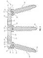
- FIG. 1is an embodiment of a coupling assembly coupled to surgical screws
- FIG. 2is an exploded view of the embodiment of the coupling assembly shown in FIG. 1 ;
- FIG. 3is a view of cross-section A-A of the embodiment of the coupling assembly shown in FIG. 1 ;
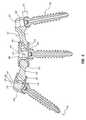
- FIG. 4is another embodiment of a coupling assembly coupled to surgical screws
- FIG. 5is an exploded view of the embodiment of the coupling assembly shown in FIG. 4 ;
- FIG. 6is a view of cross-section B-B of the embodiment of the coupling assembly shown in FIG. 4 ;
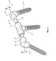
- FIG. 7is another embodiment of a coupling assembly coupled to surgical screws
- FIG. 8is an exploded view of the embodiment of the coupling assembly shown in FIG. 7 ;
- FIG. 9is a view of cross-section C-C of the embodiment of the exploded view of the coupling assembly shown in FIG. 8 ;
- FIG. 10is a detail view of a partially assembled embodiment of the coupling assembly shown in FIG. 9 ;
- FIG. 11is another detail view of a partially assembled embodiment of the coupling assembly shown in FIG. 9 ;
- FIG. 12is a detail view of an assembled embodiment of the coupling assembly shown in FIG. 9 .
- FIGS. 1-3a surgical screw system 100 that includes a plurality of various embodiments of coupling assemblies 102 disclosed herein are illustrated connecting three surgical screws 150 having a threaded portion 162 together.
- various embodiments of coupling systemare capable of being used with a variety of orthopedic rod placement devices, hooks, and/or surgical screws, including, but not limited to, pedicle screws and orthopedic rods used in spinal surgery.
- the coupling assembly 100is sometimes referred to as a yolk or tulip assembly, but for purposes of this disclosure the more generic term coupling assembly will be used.
- the coupling assembly 102includes at least one body 104 ; thus, an entire coupling assembly 102 may include a plurality of bodies 104 , such as the three bodies 104 illustrated in FIG. 1 .
- the body 104is illustrated as having a cylindrical shape, although other shapes such as ovoid, spherical, square, and so forth fall within the scope of the disclosure.
- the body 104includes an upper bore 106 .
- the body 104also optionally includes one or more female members 122 , one or more male members 124 , or a combination of female members 122 and male members 124 .
- FIG. 1illustrates bodies 104 that have one or two male members 124 and/or female members 122 , one having skill in the art would understand that a body 104 could have 3, 4, or more male members 124 and/or female members 122 , depending on the intended purpose of the coupling assembly 102 .
- the male membercan be rigid, semi-rigid, or flexible, depending on the application.
- the surgical screws 150include a threaded portion 162 configured to engage the bone of a patient as part of an orthopedic surgical procedure.
- the surgical screws 150have a head portion 152 that is received by the coupling assembly 102 as will be discussed in further detail below.
- the head portion 152has a height 156 and an outer diameter 154 .
- the head portion 152also includes a driving feature 160 for use with various tools to drive the surgical screw 150 into the bone. Illustrated in FIG. 2 , the driving feature 160 is an Allen-key or hex-head configuration, although other configurations are known in the art, such as hex-a-lobe.
- the surgical screw 150includes a screw long axis 166 and a screw cannula 164 , illustrated in the cross-section A-A in FIG. 3 .
- the screw cannula 164allows the surgical screw to be maneuvered over and to receive a Kirschner wire (typically referred to as a K-wire; not illustrated), a type of guide wire used to aid in the precise placement of the surgical screw in the bone.
- a Kirschner wiretypically referred to as a K-wire; not illustrated
- the male member 124includes a long axis 132 that aligns, to a greater or lesser degree with a first axis 134 of the body.
- alignit is meant that the long axis 132 and the first axis 134 will be approximately coincident when the male member 124 is inserted via a force 142 into the female member 122 of the body 104 .
- a first angle 133between the intersection of the long axis 132 and the first axis 134 , for which the prior art could not easily accommodate or easily allow.
- the body 104optionally includes a cannula 114 having a cannula inner diameter (or height, if the cannula is not cylindrical) 115 .
- the cannula 114is connected to the upper bore 106 and provides a route for any fluids, such as blood, entrapped in the female member 122 to escape when the male member 124 is inserted into the female member 122 .
- the female member 122has a female inner diameter (or height, if the female member 122 is not cylindrical) 123 and the male member 124 has an outer diameter (or height, if the male member 124 is not cylindrical) 126 .
- the female member 122is configured to receive and to provide an interference fit or press fit to the male member 124 .
- the term interference fitshall be interpreted broadly as including the joining of any two mating parts such that one or the other (or both) parts slightly deviate in size from their nominal dimension, thereby deforming each part slightly, each being compressed, the interface between two parts creating a union of extremely high friction.
- the word interferencerefers to the fact that one part slightly interferes with the space that the other is occupying in its nominal dimension.
- the interference fitcan be configured to require at least 800 pounds of force to remove the male member 124 from the female member 122 .
- the female inner diameter 123can be constant, or it can be sloped or have steps through the inner length of the female member 122 up until a shoulder 128 that prevents the male member 124 from advancing any further into the female member 122 .
- the female inner diameter 123may be larger than an interference fit diameter near a mouth of the female member 122 , thereby allowing the male member 124 to rotate, pivot, enter, and exit freely or semi-freely within the female member 122 .
- the female inner diameter 123optionally necks down, becoming smaller or narrower, either smoothly or in steps, until an interference fit is achieved.
- the female member 122optionally provides, in part, the ability to adjust the distance 140 between bodies 104 .
- the shoulder 128optionally narrows or necks down from the female inner diameter 123 to the cannula inner diameter 115 , or it can optionally neck down in steps.
- the shoulder 128optionally includes a lip or ridge that prevents a male face 130 of the male member 124 from advancing beyond the shoulder 128 .
- the body or bodies 104include an upper bore 106 having a bore inner diameter (or width, if the upper bore 106 is not cylindrical) 107 .
- the upper bore 106is fluidly connected to the cannula 114 .
- the upper bore 106is also fluidly connected to the receptacle 108 .
- the bore inner diameter 107is less than the receptacle inner diameter (or width, if the receptacle 108 is not cylindrical) 109 .
- the bore inner diameter 107is sufficiently wide to accommodate a K-wire or other guiding mechanism threaded through the screw cannula 164 as discussed above.
- the receptacle 108in addition to the receptacle inner diameter 109 , has a height 111 and a shoulder, or screw head contact surface 110 . As with the female member 122 , the receptacle 108 is configured to receive a head portion 152 of the surgical screw 150 and to provide an interference or press fit between the receptacle 108 and the head portion 152 .
- the receptacle inner diameter 109can be constant, or it can be sloped or have steps though the inner height 111 of the receptacle 108 up until the screw head contact surface or shoulder 110 that prevents the head portion 152 from advancing any further into the receptacle 108 .
- the receptacle inner diameter 109may be larger than an interference fit diameter near a mouth of the receptacle 108 , thereby allowing the head portion 152 to rotate, enter, and exit freely or semi-freely within the receptacle 108 .
- the receptacle inner diameter 109optionally necks down, becoming smaller or narrower, either smoothly or in steps, until an interference fit is achieved.
- the body 104 and, hence, the receptacle 108includes a second axis 136 .
- the second axis 136may align, to a greater or lesser degree with the screw long axis 166 of the surgical screw 150 , as is the case for the middle body 104 .
- alignit is meant that the screw long axis 166 and the second axis 136 will be approximately coincident when the head portion 152 of the surgical screw 150 is inserted into the receptacle 108 of the body 104 .
- the screw long axis 166 and the second axis 136be coincident due to the tolerances of the manufacturing and surgical placement process, simple variances in the anatomies between patients and other factors.
- the screw long axis 166intersects the second axis 136 of the body at a second angle 137 , as illustrated in the left most body 104 of FIG. 3 , for which the prior art could not easily accommodate or easily allow.
- FIGS. 4-6another embodiment of a surgical screw system 200 that includes a plurality of another embodiment of coupling assemblies 202 disclosed herein are illustrated connecting three surgical screws 150 having a threaded portion 162 together.
- the surgical screws 150 illustratedwere previously described above, thus reference should be made to that description.
- the coupling assembly 202includes at least one body 204 ; thus, an entire coupling assembly 202 may include a plurality of bodies 204 , such as the three bodies 204 illustrated in FIG. 4 .
- the body 204is illustrated as having a cylindrical shape, although other shapes such as ovoid, spherical, square, and so forth fall within the scope of the disclosure.
- the body 204includes an upper bore 206 .
- the body 204also optionally includes one or more female members 222 , one or more male members 224 , a combination of female members 222 and male members 224 , and, optionally, a coupling rod 220 that includes two or more male members 224 or female members 222 .
- FIG. 4illustrates bodies 204 that have one or two male members 224 and/or female members 222 , and one coupling rod 220 , one having skill in the art would understand that a body 204 could have 3, 4, or more male members 224 and/or female members 222 and/or coupling rods 220 , depending on the intended purpose of the coupling assembly 202 .
- the male member 224 and the coupling rod 220include a long axis 232 (not illustrated on the coupling rod 220 ) that aligns, to a greater or lesser degree with a first axis 234 of the body.
- alignit is meant that the long axis 232 and the first axis 234 will be approximately coincident when the male member 224 (whether included with a body 204 or a coupling rod 220 ) is inserted via a force 242 ( FIG. 5 ) into the female member 222 of the body 204 .
- this embodimentoptionally includes a male member 224 that has male face 230 that is a sphere in this instance, although other shapes and configurations, including ovoid, square, and the like, fall within the scope of the disclosure.
- An advantage of the male face 230 of spherical shapeis that provides for a greater range of motion and possible angles 233 than may otherwise be accommodated, thus providing greater ease of use and accommodation for a wider variety of factors that a surgeon might encounter while connecting the coupling assembly to a surgical screw or screws.
- the body 204optionally includes a cannula 214 having a cannula inner diameter (or height, if the cannula is not cylindrical) 215 .
- the cannula 214is connected to the upper bore 206 and provides a route for any fluids, such as blood, entrapped in the female member 222 to escape when the male member 224 is inserted into the female member 222 .
- the female member 222has a female inner diameter (or height, if the female member 222 is not cylindrical) 223 and the male member 224 includes the male face 230 that has an outer diameter (or height, if the male member 224 is not cylindrical) 226 .
- the female member 222is configured to receive and to provide an interference fit or press fit to the male face 230 of the male member 224 .
- the female inner diameter 223can be constant, or it can be sloped or have steps though the inner length of the female member 222 up until a shoulder 228 that prevents the male face 230 of the male member 224 from advancing any further into the female member 222 .
- the female inner diameter 223may be larger than an interference fit diameter near a mouth of the female member 222 , thereby allowing the male face 230 of the male member 224 to rotate, enter, and exit freely or semi-freely within the female member 222 .
- the female inner diameter 223optionally necks down, becoming smaller or narrower, either smoothly or in steps, until an interference fit is achieved.
- the female member 222optionally provides, in part, the ability to adjust the distance 240 ( FIG. 4 ) between bodies 204 .
- the shoulder 228optionally narrows or necks down from the female inner diameter 223 to the cannula inner diameter 215 , or it can optionally neck down in steps.
- the shoulder 228optionally includes a lip or ridge that prevents the male face 230 of the male member 224 from advancing beyond the shoulder 228 .
- the body or bodies 204include an upper bore 206 having a bore inner diameter (or width, if the upper bore 206 is not cylindrical) 207 .
- the upper bore 206is fluidly connected to the cannula 214 .
- the upper bore 206is also fluidly connected to the receptacle 208 .
- the bore inner diameter 207is less than the receptacle inner diameter (or width, if the receptacle 208 is not cylindrical) 209 .
- the bore inner diameter 207is sufficiently wide to accommodate a K-wire or other guiding mechanism threaded through the screw cannula 164 as discussed above.
- the receptacle 208in addition to the receptacle inner diameter 209 ( FIG. 5 ), has a height 211 and a shoulder, or screw head contact surface 210 , as illustrated in FIG. 6 .
- the receptacle 208is configured to receive a head portion 152 of the surgical screw 150 and to provide an interference or press fit between the receptacle 208 and the head portion 152 .
- the receptacle inner diameter 209can be constant, or it can be sloped or have steps though the inner height 211 of the receptacle 208 up until the screw head contact surface or shoulder 210 that prevents the head portion 152 from advancing any further into the receptacle 208 .
- the receptacle inner diameter 209may be larger than an interference fit diameter near a mouth of the receptacle 208 , thereby allowing the head portion 152 to rotate, pivot, enter, and exit freely or semi-freely within the receptacle 208 .
- the receptacle inner diameter 209optionally necks down, becoming smaller or narrower, either smoothly or in steps, until an interference fit is achieved.
- the body 204 and, hence, the receptacle 208includes a second axis 236 .
- the second axis 236may align, to a greater or lesser degree with the screw long axis 166 of the surgical screw 150 , as is the case for the middle body 204 .
- alignit is meant that the screw long axis 166 and the second axis 236 will be approximately coincident when the head portion 152 of the surgical screw 150 is inserted into the receptacle 208 of the body 204 .
- the screw long axis 166 and the second axis 236be coincident due to the tolerances of the manufacturing and surgical placement process, simple variances in the anatomies between patients and other factors.
- the screw long axis 166intersects the second axis 236 of the body at a second angle 237 , as illustrated in the left most body 104 of FIG. 3 , for which the prior art could not easily accommodate or easily allow.
- FIGS. 7-12another embodiment of a surgical screw system 300 that includes a plurality of another embodiment of coupling assemblies 302 disclosed herein are illustrated connecting three surgical screws 350 having a threaded portion 362 together.
- the coupling assembly 302includes at least one body 304 ; thus, an entire coupling assembly 302 may include a plurality of bodies 304 , such as the three bodies 304 illustrated in FIG. 7 .
- the body 304is illustrated as having a cylindrical shape, although other shapes such as ovoid, spherical, square, and so forth fall within the scope of the disclosure.
- the body 304includes an upper bore 306 .
- the body 304also optionally includes one or more female members 322 , one or more male members 324 , a combination of female members 322 and male members 324 , and, optionally, a coupling rod 320 that includes two or more male members 324 or female members 322 .
- FIG. 7illustrates bodies 304 that have one or two male members 324 and/or female members 322 , and one coupling rod 320 , one having skill in the art would understand that a body 304 could have 3, 4, or more male members 324 and/or female members 322 and/or coupling rods 320 , depending on the intended purpose of the coupling assembly 302 .
- the surgical screws 350include a threaded portion 362 configured to engage the bone of a patient as part of an orthopedic surgical procedure.
- the surgical screws 350have a head portion 352 that is received by the coupling assembly 302 as will be discussed in further detail below.
- the head portion 352has a height 356 and an outer diameter 354 . It will be noted, in comparison to the head portion 152 of FIGS. 1-6 , the head portion 352 does not have an extended spherical shape to it, although it is optional to have such a shape.
- the head portion 352also includes a driving feature 360 for use with various tools to drive the surgical screw 350 into the bone.
- the driving feature 160is an Allen-key or hex-head configuration, although other configurations are known in the art.
- the surgical screw 350includes a screw long axis 366 ( FIG. 11 ) and a screw cannula 364 , illustrated in the cross-section C-C in FIG. 9 .
- the screw cannula 364allows the use of a K-wire or other guiding mechanism, as discussed above.
- the male member 324 and the coupling rod 320include a long axis 232 that aligns, to a greater or lesser degree with a first axis 334 of the body 304 .
- alignit is meant that the long axis 332 and the first axis 334 will be approximately coincident when the male member 324 (whether included with a body 304 or a coupling rod 320 ) is inserted via a force 342 ( FIG. 9 ) into the female member 322 of the body 304 .
- the body 304optionally includes a cannula 314 having a cannula inner diameter (or height, if the cannula is not cylindrical) 315 .
- the cannula 314is connected to the upper bore 306 and provides a route for any fluids, such as blood, entrapped in the female member 322 to escape when the male member 324 is inserted into the female member 322 .
- the female member 322has a female inner diameter (or height, if the female member 322 is not cylindrical) 323 and the male member 324 includes the male face 330 that has an outer diameter (or height, if the male member 324 is not cylindrical) 326 .
- the female member 322is configured to receive and to provide an interference fit or press fit to the male face 330 of the male member 324 .
- embodiments of the male face 330 illustrated in FIG. 8includes a locking mechanism 331 , such as a hex head, threads, flutes, ridges, and other similar types of locking mechanisms to engage the female member 322 in a locking arrangement as an alternative to or, optionally, as a supplement to, the interference fit.
- the locking mechanism 331optionally can be included on just one or both of the male faces 330 of the coupling rod 320 .
- the locking mechanism 331can be engaged to interface with the female member 322 by rotating the coupling rod 320 and/or the male member 324 in the direction 344 around a long axis 332 , as illustrated in FIGS. 9 and 11 .
- the locking mechanism 331 on the male faces 330 of the coupling rod 320can be configured to be the same or different.
- a first locking mechanism 331 aoptionally has right hand threads
- the locking mechanism 331 boptionally has left hand threads.
- the coupling rod 320need only be rotated in the direction 344 , thereby engaging both locking mechanisms 331 a and 331 b near simultaneously.
- the female inner diameter 323can be constant, or it can be sloped or have steps though the inner length of the female member 322 up until a shoulder 328 that prevents the male face 330 of the male member 324 from advancing any further into the female member 322 .
- the female inner diameter 323may be larger than an interference fit diameter near a mouth of the female member 322 , thereby allowing the male face 330 of the male member 324 to rotate, enter, and exit freely or semi-freely within the female member 322 before engaging any locking mechanism 331 .
- the female inner diameter 323optionally necks down, becoming smaller or narrower, either smoothly or in steps, until an interference fit is achieved and/or the locking mechanism 331 is engaged.
- the female member 322optionally provides, in part, the ability to adjust the distance 340 ( FIG. 7 ) between bodies 304 .
- the shoulder 328optionally narrows or necks down from the female inner diameter 323 to the cannula inner diameter 315 , or it can optionally neck down in steps.
- the shoulder 328optionally includes a lip or ridge that prevents the male face 330 of the male member 324 from advancing beyond the shoulder 328 .
- the body or bodies 304include an upper bore 306 having a bore inner diameter (or width, if the upper bore 306 is not cylindrical) 307 .
- the upper bore 306is fluidly connected to the cannula 314 .
- the upper bore 306is also fluidly connected to the receptacle 308 .
- the bore inner diameter 307is less than the receptacle inner diameter (or width, if the receptacle 308 is not cylindrical) 309 .
- the bore inner diameter 307is sufficiently wide to accommodate a K-wire or other guiding mechanism threaded through the screw cannula 364 as discussed above.
- the receptacle 308in addition to the receptacle inner diameter 309 ( FIG. 9 ), has a height 311 and a shoulder, or contact surface 310 , as illustrated in FIG. 6 .
- the receptacle 308is optionally configured to receive a head portion 352 of the surgical screw 350 and to provide an interference or press fit between the receptacle 308 and the head portion 352 .
- the receptacle inner diameter 309can be constant, or it can be sloped or have steps though the inner height 311 of the receptacle 308 up until the contact surface or shoulder 310 that prevents the head portion 352 from advancing any further into the receptacle 308 .
- the receptacle inner diameter 309may be larger than an interference fit diameter near a mouth of the receptacle 308 , thereby allowing the head portion 352 to rotate, enter, and exit freely or semi-freely within the receptacle 308 .
- the receptacle inner diameter 309optionally necks down, becoming smaller or narrower, either smoothly or in steps, until an interference fit is achieved.
- the receptacle 308can be configured to receive a split-ring 380 .
- the split ring 380includes a plurality of fingers 383 separated by slots 382 .
- the split-ring 380has a height 392 , an split-ring outer diameter 390 , a recess 394 having a recess inner diameter 386 , and an optional flat top 390 .
- the split-ring 80is configured to receive the head portion 352 of the surgical screw 350 within the recess 394 .
- the fingers 383elastically deform, such as with a spring-like manner, to engage and grasp the head portion 352 of the surgical screw 350 .
- the recess 394includes a channel or slot 384 configured to engage a lip or ridge 359 on the head portion 352 of the surgical screw 350 to better secure the head portion 352 within the recess 394 of the split-ring 380 .
- a benefit of the split ring 380is that it elastically, and thus easily, engages and disengages from the head portion 352 of a surgical screw 350 that has been implanted in a bone, thus more easily allowing for adjustment of the body 304 and, therefore, the coupling assembly 302 , during a procedure.
- the split-ring 380may be partially received within the receptacle 308 initially ( FIGS. 10 and 11 ) or it may engage the head portion 352 of the surgical screw 350 prior to being received by the receptacle 308 (not shown). Regardless, once properly adjusted and positioned, the receptacle 308 receives the split ring 380 therein with an interference fit as illustrated in FIG. 12 and as described above vis-à-vis the embodiments in which the receptacle 108 , 208 , 308 directly engage a head portion 152 , 352 of the surgical screw 150 , 350 .
- the body 304 and, hence, the receptacle 308includes a second axis 336 .
- the second axis 336may align, to a greater or lesser degree with the screw long axis 366 of the surgical screw 352 .
- alignit is meant that the screw long axis 366 and the second axis 336 will be approximately coincident when the head portion 352 of the surgical screw 350 is inserted into the receptacle 308 of the body 304 .
- the screw long axis 366 and the second axis 336be coincident due to the tolerances of the manufacturing and surgical placement process, simple variances in the anatomies between patients and other factors.
- the screw long axis 366intersects the second axis 336 of the body at a second angle 337 , as illustrated in FIG. 12 , for which the prior art could not easily accommodate or easily allow.
- embodiments of coupling assemblies disclosed hereinare suitable for surgical orthopedic procedures, such as stabilize fractures, the spine, and other similar procedures.
- a surgeontypically, although not necessarily, implanted one or more surgical screws into a bone of a patient, often with the aid of a K-wire or other guiding mechanism. It is typically desirable to couple that first surgical screw to another surgical screw with a coupling assembly to provide stability, rigidity, and, optionally, a platform for other devices, such as fusion rods, plates, and the like.
- surgeonswere required to have available coupling assemblies and their components in many different lengths and shapes to accommodate various factors, including manufacturing tolerances, a patient's particular anatomy and injury that would require placement of the surgical screws in a potentially infinite variety of locations, and slight variation from a desired location of the surgical screw that may occur during the procedure.
- prior art devicestypically required locking screws, nuts, crimping tools, and other similar devices to effect a fixed connection between the coupling assembly and the surgical screw.
- Rigid rods with inflexible connections and/or through-holes into which the rods were positioned, as disclosed in prior art devices,could not easily accommodate the various factors discussed above and, at times, a surgeon would have to bend the rod.
- the prior art deviceshad a larger profile, typically resulting in more pain to the patient and required more parts, thereby increasing the complexity of the process and increasing the risk that a component might be misplaced or lost.
- Embodiments of the coupling assemblies disclosed hereinhave fewer parts, accommodate a variety of tolerances, angles, and other factors that occur during any surgical procedure, allow for adjustment during the procedure, and other benefits as discussed above and will be discussed here. While reference will be made to the embodiments disclosed above in reference to FIGS. 7-12 , it will be understood by one of skill in the art that embodiments of these methods and variations thereof apply to each of the embodiments disclosed herein.
- Embodiments of the methods of implanting a coupling assembly 302therefore, include obtaining a first body 304 and a second body 304 , each body 304 including an upper bore 302 and a receptacle 308 configured to receive a head portion 352 of a surgical screw 350 that has been implanted in a patient.
- the receptacle 308provides an interference fit with the head portion 352 and, optionally, a split-ring 380 , as described above.
- the body 304also includes at least one of a male member 324 , female member 322 , and, optionally, a coupling rod 320 that includes a male member 324 .
- the receptacle 308is positioned on the head portion 352 and/or a split-ring 380 so that the body 304 can move relative to the head portion 352 .
- the male member 324is positioned within the female member 322 so that the body 304 and the female member 322 can move relative to the male member 324 , which can reduce the likelihood that a rigid rod would have to be bent to accommodate a fixed coupling system.
- the coupling assembly 302can be assembled and disassembled easily, perhaps many times, before the interference fit is engaged.
- the coupling assembly 302can be assembled in-situ or before hand—a step eased by the flexibility and adaptability provided by the disclosed embodiments—providing further ease of use compared to prior art devices.
- the interference fit of the female member 322 and the receptacle 308is then engaged (in either order or simultaneously) with the male member 324 and the head portion 352 , respectively.
- the angle between the first axis 334 and the long axis 332 , as well as the second axis 336 and the screw long axis 337can be adjusted and accommodated for misalignment and for the various factors noted above.
- the distance 340 between bodiescan be adjusted by adjusted the depth to which the male member 324 is inserted into the female member 322 , thereby accommodating for the various factors noted above.
- the relative height of the body 304 above the head portion 352can be adjusted by adjusted the depth to which the head portion 352 (or split-ring 380 ) is inserted into the receptacle 308 , thereby accommodating a higher or lower profile as desired and thereby providing a lower profile assembly than prior art devices that use set screws and the like.
- the male member 324include a male face 330 with a locking mechanism 331 , the locking mechanism can be engaged as disclosed above.
- Methods of making embodiments of the coupling assembliesinclude forming a first body 308 that includes an upper bore 308 , a receptacle 308 , at least one of a male member 324 , a female member 322 , and, optionally, a coupling rod 320 .
- the female member 322is configured to receive the male member 324 .
- the male member 324is configured to have a male face 330 that includes a locking mechanism 331 as described above.
- the receptacle 308is formed and configured to receive a head portion 352 of a surgical screw 350 and/or a split-ring 380 that, in turn, is formed and configured to receive a head portion 352 of the surgical screw 350 .
- the present inventionin various embodiments, includes providing devices and processes in the absence of items not depicted and/or described herein or in various embodiments hereof, including in the absence of such items as may have been used in previous devices or processes, e.g., for improving performance, achieving ease and/or reducing cost of implementation.
Landscapes
- Health & Medical Sciences (AREA)
- Orthopedic Medicine & Surgery (AREA)
- Life Sciences & Earth Sciences (AREA)
- Neurology (AREA)
- Surgery (AREA)
- Heart & Thoracic Surgery (AREA)
- Engineering & Computer Science (AREA)
- Biomedical Technology (AREA)
- Nuclear Medicine, Radiotherapy & Molecular Imaging (AREA)
- Medical Informatics (AREA)
- Molecular Biology (AREA)
- Animal Behavior & Ethology (AREA)
- General Health & Medical Sciences (AREA)
- Public Health (AREA)
- Veterinary Medicine (AREA)
- Surgical Instruments (AREA)
Abstract
Description
Claims (10)
Priority Applications (5)
| Application Number | Priority Date | Filing Date | Title |
|---|---|---|---|
| US12/711,131US9232965B2 (en) | 2009-02-23 | 2010-02-23 | Press-on link for surgical screws |
| US14/757,080US9801667B2 (en) | 2007-12-07 | 2015-11-16 | Instruments, tools, and methods for presson pedicle screws |
| US14/994,006US20160120576A1 (en) | 2009-02-23 | 2016-01-12 | Press-On Link for Surgical Screws |
| US14/998,660US20170020571A1 (en) | 2007-12-07 | 2016-01-28 | Additive manufacturing for spinal implants |
| US18/828,985US20240423676A1 (en) | 2009-02-23 | 2024-09-09 | Press-on link for surgical screws |
Applications Claiming Priority (2)
| Application Number | Priority Date | Filing Date | Title |
|---|---|---|---|
| US15451109P | 2009-02-23 | 2009-02-23 | |
| US12/711,131US9232965B2 (en) | 2009-02-23 | 2010-02-23 | Press-on link for surgical screws |
Related Child Applications (1)
| Application Number | Title | Priority Date | Filing Date |
|---|---|---|---|
| US14/994,006ContinuationUS20160120576A1 (en) | 2009-02-23 | 2016-01-12 | Press-On Link for Surgical Screws |
Publications (2)
| Publication Number | Publication Date |
|---|---|
| US20100217334A1 US20100217334A1 (en) | 2010-08-26 |
| US9232965B2true US9232965B2 (en) | 2016-01-12 |
Family
ID=42631638
Family Applications (3)
| Application Number | Title | Priority Date | Filing Date |
|---|---|---|---|
| US12/711,131Active - Reinstated2031-02-18US9232965B2 (en) | 2007-12-07 | 2010-02-23 | Press-on link for surgical screws |
| US14/994,006PendingUS20160120576A1 (en) | 2009-02-23 | 2016-01-12 | Press-On Link for Surgical Screws |
| US18/828,985PendingUS20240423676A1 (en) | 2009-02-23 | 2024-09-09 | Press-on link for surgical screws |
Family Applications After (2)
| Application Number | Title | Priority Date | Filing Date |
|---|---|---|---|
| US14/994,006PendingUS20160120576A1 (en) | 2009-02-23 | 2016-01-12 | Press-On Link for Surgical Screws |
| US18/828,985PendingUS20240423676A1 (en) | 2009-02-23 | 2024-09-09 | Press-on link for surgical screws |
Country Status (3)
| Country | Link |
|---|---|
| US (3) | US9232965B2 (en) |
| EP (1) | EP2408389B1 (en) |
| WO (1) | WO2010096829A2 (en) |
Cited By (10)
| Publication number | Priority date | Publication date | Assignee | Title |
|---|---|---|---|---|
| US20150034766A1 (en)* | 2013-08-01 | 2015-02-05 | Airbus Operations (S.A.S) | Tool for simultaneously holding several attachment clips in contact with an aircraft fuselage frame element |
| US20160030091A1 (en)* | 2012-11-06 | 2016-02-04 | Globus Medical, Inc. | Low profile connectors |
| US20160074074A1 (en)* | 2014-09-12 | 2016-03-17 | Nexus Spine, LLC | PressOn Pedicle Screw Variations |
| WO2017143110A1 (en) | 2016-02-16 | 2017-08-24 | Nexus Spine, LLC | Revision system for spinal implants |
| US9745043B2 (en) | 2013-08-01 | 2017-08-29 | Airbus Operations (S.A.S.) | Aircraft fuselage frame element integrating tabs for the fastening of stiffeners |
| US10595907B2 (en) | 2017-02-16 | 2020-03-24 | Rubicon Spine Llc | Polyaxial pedicle screw |
| US11141229B2 (en) | 2016-06-03 | 2021-10-12 | Rubicon Spine Llc | Dynamic feedback end effector |
| US20230240724A1 (en)* | 2019-05-22 | 2023-08-03 | Nuvasive, Inc. | Posterior spinal fixation screws |
| USD1037845S1 (en)* | 2022-11-08 | 2024-08-06 | Madhu Sudan Saini | Screw |
| US12364511B2 (en) | 2006-12-07 | 2025-07-22 | Nexus Spine, LLC | Press-on pedicle screw assembly |
Families Citing this family (35)
| Publication number | Priority date | Publication date | Assignee | Title |
|---|---|---|---|---|
| US20180228621A1 (en) | 2004-08-09 | 2018-08-16 | Mark A. Reiley | Apparatus, systems, and methods for the fixation or fusion of bone |
| US8308801B2 (en)* | 2007-02-12 | 2012-11-13 | Brigham Young University | Spinal implant |
| US9314346B2 (en) | 2007-02-12 | 2016-04-19 | Brigham Young University | Spinal implant |
| US20170020571A1 (en)* | 2007-12-07 | 2017-01-26 | Nexus Spine, LLC | Additive manufacturing for spinal implants |
| US8894687B2 (en) | 2011-04-25 | 2014-11-25 | Nexus Spine, L.L.C. | Coupling system for surgical construct |
| CA2743721A1 (en) | 2009-02-19 | 2010-08-26 | Anton E. Bowden | Compliant dynamic spinal implant |
| WO2010096829A2 (en) | 2009-02-23 | 2010-08-26 | Crocker Spinal, L.L.C. | Press-on link for surgical screws |
| US9157497B1 (en) | 2009-10-30 | 2015-10-13 | Brigham Young University | Lamina emergent torsional joint and related methods |
| EP2460484A1 (en)* | 2010-12-01 | 2012-06-06 | FACET-LINK Inc. | Variable angle bone screw fixation assembly |
| WO2012177412A2 (en) | 2011-06-07 | 2012-12-27 | Brigham Young University | Serpentine spinal stability device and associated methods |
| US8758411B1 (en) | 2011-10-25 | 2014-06-24 | Nuvasive, Inc. | Implants and methods for treating spinal disorders |
| US9044321B2 (en) | 2012-03-09 | 2015-06-02 | Si-Bone Inc. | Integrated implant |
| US10363140B2 (en) | 2012-03-09 | 2019-07-30 | Si-Bone Inc. | Systems, device, and methods for joint fusion |
| EP3818947B1 (en) | 2012-05-04 | 2023-08-30 | SI-Bone, Inc. | Fenestrated implant |
| US9232966B2 (en) | 2012-09-24 | 2016-01-12 | Refai Technologies, Llc | Articulating spinal rod system |
| EP2911599B1 (en)* | 2012-10-23 | 2020-04-29 | Nexus Spine, L.L.C. | Surgical construct coupling system |
| WO2014145902A1 (en) | 2013-03-15 | 2014-09-18 | Si-Bone Inc. | Implants for spinal fixation or fusion |
| FR3010893B1 (en)* | 2013-09-25 | 2017-03-03 | Spineway | DEVICE FOR CONNECTING SPINAL IMPLANTS |
| US11147688B2 (en) | 2013-10-15 | 2021-10-19 | Si-Bone Inc. | Implant placement |
| US9642651B2 (en) | 2014-06-12 | 2017-05-09 | Brigham Young University | Inverted serpentine spinal stability device and associated methods |
| JP6542362B2 (en) | 2014-09-18 | 2019-07-10 | エスアイ−ボーン・インコーポレイテッドSi−Bone, Inc. | Matrix implant |
| US10166033B2 (en) | 2014-09-18 | 2019-01-01 | Si-Bone Inc. | Implants for bone fixation or fusion |
| US10004538B2 (en)* | 2016-04-27 | 2018-06-26 | Warsaw Orthopedic, Inc. | Surgical instrument and method |
| US11116519B2 (en) | 2017-09-26 | 2021-09-14 | Si-Bone Inc. | Systems and methods for decorticating the sacroiliac joint |
| ES3011907T3 (en) | 2018-03-28 | 2025-04-08 | Si Bone Inc | Threaded implants for use across bone segments |
| EP4613244A2 (en) | 2019-02-14 | 2025-09-10 | SI-Bone Inc. | Implants for spinal fixation and or fusion |
| US11369419B2 (en) | 2019-02-14 | 2022-06-28 | Si-Bone Inc. | Implants for spinal fixation and or fusion |
| DE102019005374A1 (en)* | 2019-07-30 | 2021-02-04 | Signus Medizintechnik Gmbh | SPINE IMPLANT CONNECTION DEVICE |
| JP7646654B2 (en) | 2019-11-21 | 2025-03-17 | エスアイ-ボーン・インコーポレイテッド | Rod coupling assembly for bone stabilization construct - Patent application |
| AU2020392121B2 (en) | 2019-11-27 | 2025-05-22 | Si-Bone, Inc. | Bone stabilizing implants and methods of placement across SI joints |
| EP4072452A4 (en) | 2019-12-09 | 2023-12-20 | SI-Bone, Inc. | Sacro-iliac joint stabilizing implants and methods of implantation |
| EP4259015A4 (en) | 2020-12-09 | 2024-09-11 | SI-Bone, Inc. | SACROILIAC JOINT STABILIZATION IMPLANTS AND METHODS OF IMPLANTATION |
| WO2022187662A1 (en)* | 2021-03-04 | 2022-09-09 | Board Of Supervisors Of Louisiana State University And Agricultural And Mechanical College | Pelvic internal fixation device and methods of using the same |
| GB202212943D0 (en)* | 2022-09-05 | 2022-10-19 | Parkes John Humphries | Improvements in or relating to mechanisms for back problems |
| WO2025038769A1 (en) | 2023-08-15 | 2025-02-20 | Si-Bone Inc. | Pelvic stabilization implants, methods of use and manufacture |
Citations (127)
| Publication number | Priority date | Publication date | Assignee | Title |
|---|---|---|---|---|
| US3945053A (en) | 1973-03-05 | 1976-03-23 | Purdue Research Foundation | Rolling contact prosthetic knee joint |
| US5405408A (en) | 1993-05-14 | 1995-04-11 | Pitkin; Mark R. | Artificial knee having dual flexion action during locomotion |
| US5415661A (en) | 1993-03-24 | 1995-05-16 | University Of Miami | Implantable spinal assist device |
| US5733285A (en) | 1995-07-13 | 1998-03-31 | Fastenetix, Llc | Polyaxial locking mechanism |
| US5772661A (en) | 1988-06-13 | 1998-06-30 | Michelson; Gary Karlin | Methods and instrumentation for the surgical correction of human thoracic and lumbar spinal disease from the antero-lateral aspect of the spine |
| US5964760A (en) | 1996-10-18 | 1999-10-12 | Spinal Innovations | Spinal implant fixation assembly |
| US6045552A (en) | 1998-03-18 | 2000-04-04 | St. Francis Medical Technologies, Inc. | Spine fixation plate system |
| US6063089A (en) | 1996-12-23 | 2000-05-16 | Spinal Concepts, Inc. | Side mounted polyaxial pedicle screw |
| EP1072228A1 (en) | 1999-07-27 | 2001-01-31 | Société Etudes et Developpements S.E.D. | Implantable intervertebral connector device |
| US6355040B1 (en) | 1998-04-03 | 2002-03-12 | Spinal Innovations, L.L.C. | Locking mechanism |
| US6379354B1 (en) | 1993-10-08 | 2002-04-30 | Chaim Rogozinski | Spinal implant and method |
| EP1224915A1 (en) | 2001-01-23 | 2002-07-24 | Stryker Spine | Position regulating system for spinal surgery instrument |
| US6440169B1 (en) | 1998-02-10 | 2002-08-27 | Dimso | Interspinous stabilizer to be fixed to spinous processes of two vertebrae |
| US20020138077A1 (en)* | 2001-03-26 | 2002-09-26 | Ferree Bret A. | Spinal alignment apparatus and methods |
| US20020151900A1 (en)* | 2001-01-12 | 2002-10-17 | Craig Glascott | Polyaxial screw with improved locking |
| US6527804B1 (en) | 1998-12-11 | 2003-03-04 | Dimso (Distribution Medicale Du Sud-Quest) | Intervertebral disk prosthesis |
| US6540785B1 (en) | 1998-10-22 | 2003-04-01 | Sdgi Holdings, Inc. | Artificial intervertebral joint permitting translational and rotational motion |
| US6572653B1 (en) | 2001-12-07 | 2003-06-03 | Rush E. Simonson | Vertebral implant adapted for posterior insertion |
| US6579320B1 (en) | 1998-12-11 | 2003-06-17 | Stryker Spine | Intervertebral disc prosthesis with contact blocks |
| US20030153912A1 (en)* | 2000-06-30 | 2003-08-14 | Henry Graf | Intervertebral connecting device |
| US6610093B1 (en) | 2000-07-28 | 2003-08-26 | Perumala Corporation | Method and apparatus for stabilizing adjacent vertebrae |
| US20030171751A1 (en) | 2002-02-20 | 2003-09-11 | Stephen Ritland | Pedicle screw connector apparatus and method |
| US6645248B2 (en) | 2001-08-24 | 2003-11-11 | Sulzer Orthopedics Ltd. | Artificial intervertebral disc |
| US20040002708A1 (en) | 2002-05-08 | 2004-01-01 | Stephen Ritland | Dynamic fixation device and method of use |
| US6723127B2 (en) | 2001-07-16 | 2004-04-20 | Spine Core, Inc. | Artificial intervertebral disc having a wave washer force restoring element |
| US20040176849A1 (en) | 2003-03-06 | 2004-09-09 | Rafail Zubok | Cervical disc replacement |
| US6793678B2 (en) | 2002-06-27 | 2004-09-21 | Depuy Acromed, Inc. | Prosthetic intervertebral motion disc having dampening |
| WO2004071344A3 (en) | 2003-02-12 | 2004-09-23 | Sdgi Holdings Inc | Mobile bearing articulating disc prothesis |
| US6802867B2 (en) | 1999-06-04 | 2004-10-12 | Depuy Acromed, Inc. | Orthopedic implant |
| US6811567B2 (en) | 1999-10-22 | 2004-11-02 | Archus Orthopedics Inc. | Facet arthroplasty devices and methods |
| US20050038432A1 (en)* | 2003-04-25 | 2005-02-17 | Shaolian Samuel M. | Articulating spinal fixation rod and system |
| US6863688B2 (en) | 2001-02-15 | 2005-03-08 | Spinecore, Inc. | Intervertebral spacer device utilizing a spirally slotted belleville washer having radially spaced concentric grooves |
| US20050101954A1 (en) | 2003-11-10 | 2005-05-12 | Simonson Peter M. | Artificial facet joint and method |
| US20050113924A1 (en) | 2003-08-07 | 2005-05-26 | Dynamic Spine, Inc. | Apparatus and method for performing spinal surgery |
| US20050113927A1 (en)* | 2003-11-25 | 2005-05-26 | Malek Michel H. | Spinal stabilization systems |
| US20050125065A1 (en) | 2003-11-05 | 2005-06-09 | St. Francis Medical Technologies Inc. | Laterally insertable artificial vertebral disk replacement implant with crossbar spacer |
| US20050149023A1 (en) | 2001-09-28 | 2005-07-07 | Stephen Ritland | Adjustable rod and connector device and method of use |
| WO2005051243A3 (en) | 2003-10-30 | 2005-07-14 | Steven Streatfield Gill | An intervertebral prosthesis |
| US20050159818A1 (en) | 2002-06-26 | 2005-07-21 | Jason Blain | Total disc replacement system and related methods |
| US20050165487A1 (en) | 2004-01-28 | 2005-07-28 | Muhanna Nabil L. | Artificial intervertebral disc |
| US20050177156A1 (en)* | 2003-05-02 | 2005-08-11 | Timm Jens P. | Surgical implant devices and systems including a sheath member |
| KR20050080493A (en) | 2004-02-09 | 2005-08-12 | 메딕스얼라인 주식회사 | An internal fixator for spine |
| US6936071B1 (en) | 1999-07-02 | 2005-08-30 | Spine Solutions, Inc. | Intervertebral implant |
| US20050192573A1 (en) | 2004-02-27 | 2005-09-01 | Custom Spine, Inc. | Biased angle polyaxial pedicle screw assembly |
| US20050203516A1 (en) | 2004-03-03 | 2005-09-15 | Biedermann Motech Gmbh | Anchoring element and stabilization device for the dynamic stabilization of vertebrae or bones using such anchoring elements |
| US6949123B2 (en) | 1999-10-22 | 2005-09-27 | Archus Orthopedics Inc. | Facet arthroplasty devices and methods |
| US20050228382A1 (en) | 2004-04-12 | 2005-10-13 | Marc Richelsoph | Screw and rod fixation assembly and device |
| US6964666B2 (en) | 2003-04-09 | 2005-11-15 | Jackson Roger P | Polyaxial bone screw locking mechanism |
| WO2005107654A1 (en) | 2004-04-22 | 2005-11-17 | Sdgi Holdings, Inc. | Prosthetic intervertebral disc |
| US6966910B2 (en) | 2002-04-05 | 2005-11-22 | Stephen Ritland | Dynamic fixation device and method of use |
| US20050261772A1 (en) | 2004-05-18 | 2005-11-24 | Zimmer Gmbh | Intervertebral disk implant |
| US6974478B2 (en) | 1999-10-22 | 2005-12-13 | Archus Orthopedics, Inc. | Prostheses, systems and methods for replacement of natural facet joints with artificial facet joint surfaces |
| US20050277932A1 (en)* | 2004-06-15 | 2005-12-15 | Sdgi Holdings, Inc. | Spinal rod system |
| US6983924B2 (en) | 2000-04-26 | 2006-01-10 | Brigham Young University | Compliant, ortho-planar, linear motion spring |
| US20060009766A1 (en)* | 2004-07-08 | 2006-01-12 | Andrew Lee | Transverse fixation device for spinal fixation systems |
| US20060009850A1 (en) | 2002-12-17 | 2006-01-12 | Mathys Medizinaltechnik Ag | Intervertebral implant |
| US20060025770A1 (en) | 2002-12-06 | 2006-02-02 | Fridolin Schlapfer | Device for stabilizing bones |
| US20060036240A1 (en) | 2004-08-09 | 2006-02-16 | Innovative Spinal Technologies | System and method for dynamic skeletal stabilization |
| US20060041314A1 (en) | 2004-08-20 | 2006-02-23 | Thierry Millard | Artificial disc prosthesis |
| US20060052784A1 (en) | 2004-08-17 | 2006-03-09 | Zimmer Spine, Inc. | Polyaxial device for spine stabilization during osteosynthesis |
| US7029475B2 (en) | 2003-05-02 | 2006-04-18 | Yale University | Spinal stabilization method |
| US20060084987A1 (en)* | 2004-10-20 | 2006-04-20 | Kim Daniel H | Systems and methods for posterior dynamic stabilization of the spine |
| US7074238B2 (en) | 2003-07-08 | 2006-07-11 | Archus Orthopedics, Inc. | Prostheses, tools and methods for replacement of natural facet joints with artificial facet joint surfaces |
| US7093827B2 (en) | 2001-11-08 | 2006-08-22 | Massachusetts Institute Of Technology | Multiple degree of freedom compliant mechanism |
| US20060189983A1 (en) | 2005-02-22 | 2006-08-24 | Medicinelodge, Inc. | Apparatus and method for dynamic vertebral stabilization |
| US20060190079A1 (en) | 2005-01-21 | 2006-08-24 | Naim Istephanous | Articulating spinal disc implants with amorphous metal elements |
| US20060217712A1 (en) | 2003-03-24 | 2006-09-28 | Richard Mueller | Spinal implant adjustment device |
| US7115129B2 (en) | 2001-10-19 | 2006-10-03 | Baylor College Of Medicine | Bone compression devices and systems and methods of contouring and using same |
| US20060229609A1 (en)* | 2005-03-18 | 2006-10-12 | Chao-Jan Wang | Microadjustment spinal joint fixture |
| US20060240533A1 (en) | 2001-06-16 | 2006-10-26 | Sengupta Dilip K | Assembly for the stabilisation of vertebral bodies of the spine |
| KR20060113318A (en) | 2005-04-27 | 2006-11-02 | 주식회사 솔고 바이오메디칼 | Spinal fixation screw |
| US20060271047A1 (en) | 2005-05-10 | 2006-11-30 | Jackson Roger P | Polyaxial bone screw with compound articulation |
| US20060271051A1 (en) | 2003-10-22 | 2006-11-30 | Pioneer Laboratories, Inc. | Crossllink for securing spinal rods |
| WO2006127992A2 (en) | 2005-05-25 | 2006-11-30 | Alphaspine, Inc. | Low profile pedicle screw and rod assembly |
| US7144396B2 (en) | 2002-02-13 | 2006-12-05 | Endius Incorporated | Apparatus for connecting a longitudinal member to a bone portion |
| US7144369B2 (en) | 1999-06-03 | 2006-12-05 | Cardiac Intelligence Corporation | System and method for providing collection and analysis of patient information for use in automated patient care |
| US20070028714A1 (en) | 2005-07-29 | 2007-02-08 | Brigham Young University | Spherical three degrees of freedom platform |
| US20070043365A1 (en) | 2005-07-19 | 2007-02-22 | Stephen Ritland | Rod extension for extending fusion construct |
| US20070049936A1 (en) | 2005-08-26 | 2007-03-01 | Dennis Colleran | Alignment instrument for dynamic spinal stabilization systems |
| WO2007041265A1 (en) | 2005-09-30 | 2007-04-12 | Paradigm Spine, Llc | Hinged polyaxial screw and methods of use |
| US20070088440A1 (en) | 2002-04-25 | 2007-04-19 | Lukas Eisermann | Articular disc prosthesis and method for implanting the same |
| US7207992B2 (en) | 2001-09-28 | 2007-04-24 | Stephen Ritland | Connection rod for screw or hook polyaxial system and method of use |
| US7229441B2 (en) | 2001-02-28 | 2007-06-12 | Warsaw Orthopedic, Inc. | Flexible systems for spinal stabilization and fixation |
| US20070179618A1 (en) | 2006-01-31 | 2007-08-02 | Sdgi Holdings, Inc. | Intervertebral prosthetic disc |
| US20070270814A1 (en)* | 2006-04-20 | 2007-11-22 | Sdgi Holdings, Inc. | Vertebral stabilizer |
| US20080015588A1 (en) | 2006-07-11 | 2008-01-17 | Hawkes David T | Transverse Connector |
| US20080027436A1 (en)* | 2006-07-14 | 2008-01-31 | John Cournoyer | Rod to Rod Connectors and Methods of Adjusting The Length Of A Spinal Rod Construct |
| US7326210B2 (en) | 2003-09-24 | 2008-02-05 | N Spine, Inc | Spinal stabilization device |
| US7338398B2 (en) | 2000-04-26 | 2008-03-04 | Brigham Young University | Continuously variable transmission or clutch with ortho-planar compliant mechanism |
| US20080071273A1 (en)* | 2006-09-15 | 2008-03-20 | Hawkes David T | Dynamic Pedicle Screw System |
| US20080077246A1 (en) | 2006-09-21 | 2008-03-27 | Fehling Ag | Vertebral disc prosthesis |
| US7371238B2 (en) | 2001-02-16 | 2008-05-13 | Queen's University At Kingston | Method and device for treating scoliosis |
| US7377942B2 (en) | 2003-08-06 | 2008-05-27 | Warsaw Orthopedic, Inc. | Posterior elements motion restoring device |
| WO2008070840A1 (en) | 2006-12-07 | 2008-06-12 | Alpinespine Llc | Press-on pedicle screw assembly |
| US20080154308A1 (en) | 2006-12-21 | 2008-06-26 | Warsaw Orthopedic, Inc. | Spinal fixation system |
| US20080167688A1 (en) | 2005-02-22 | 2008-07-10 | Facet Solutions, Inc. | Taper-Locking Fixation System |
| US20080183209A1 (en) | 2005-09-23 | 2008-07-31 | Spinal Kinetics, Inc. | Spinal Stabilization Device |
| US20080195213A1 (en) | 2007-02-12 | 2008-08-14 | Brigham Young University | Spinal implant |
| US20080195208A1 (en) | 2007-02-09 | 2008-08-14 | Altiva Corporation | Dynamic stabilization device |
| EP1970031A2 (en) | 2007-03-13 | 2008-09-17 | Zimmer Spine, Inc. | Dynamic spinal stabilization system and method of using the same |
| US7445635B2 (en) | 2001-03-02 | 2008-11-04 | Facet Solutions | Method and apparatus for spine joint replacement |
| US7458981B2 (en) | 2004-03-09 | 2008-12-02 | The Board Of Trustees Of The Leland Stanford Junior University | Spinal implant and method for restricting spinal flexion |
| US20080312693A1 (en) | 2006-12-10 | 2008-12-18 | Paradigm Spine, Llc. | Posterior Functionally Dynamic Stabilization System |
| US20090005819A1 (en) | 2007-05-22 | 2009-01-01 | Eden Spine, Llc | Interspinous vertebral implant |
| US7476251B2 (en) | 2002-10-29 | 2009-01-13 | Kyphon Sarl | Interspinous process apparatus and method with a selectably expandable spacer |
| US7481830B2 (en) | 1999-07-07 | 2009-01-27 | Children's Hospital Medical Center | Spinal correction system |
| US7485146B1 (en) | 2004-03-08 | 2009-02-03 | Nuvasive, Inc. | Total disc replacement system and related methods |
| US7485134B2 (en) | 2001-12-07 | 2009-02-03 | Simonson Rush E | Vertebral implants adapted for posterior insertion |
| US7485133B2 (en) | 2004-07-14 | 2009-02-03 | Warsaw Orthopedic, Inc. | Force diffusion spinal hook |
| US7491240B1 (en) | 2005-10-10 | 2009-02-17 | Donna Jean Carver | Artificial spinal disc replacement system and method |
| US7491218B2 (en) | 2002-10-30 | 2009-02-17 | Abbott Spine, Inc. | Spinal stabilization systems and methods using minimally invasive surgical procedures |
| US7491238B2 (en) | 2004-12-23 | 2009-02-17 | Impliant Ltd. | Adjustable spinal prosthesis |
| US20090048631A1 (en) | 2007-08-17 | 2009-02-19 | Bhatnagar Mohit K | Dynamic Stabilization Device for Spine |
| US7494507B2 (en) | 2000-01-30 | 2009-02-24 | Diamicron, Inc. | Articulating diamond-surfaced spinal implants |
| US7537615B2 (en) | 2005-04-15 | 2009-05-26 | Eden Spine Europe Sa | Intervertebral disk prosthesis |
| US20090171392A1 (en)* | 2007-12-04 | 2009-07-02 | Javier Garcia-Bengochea | Guide wire mounting collar for spinal fixation using minimally invasive surgical techniques |
| US20090228045A1 (en) | 2004-10-20 | 2009-09-10 | Stanley Kyle Hayes | Dynamic rod |
| US20090259257A1 (en) | 2008-04-15 | 2009-10-15 | Warsaw Orthopedic, Inc. | Pedicule-Based Motion- Preserving Device |
| US20090270921A1 (en) | 2008-02-14 | 2009-10-29 | Krause William R | Flexible spine components having a concentric slot |
| US7618441B2 (en) | 2002-01-22 | 2009-11-17 | Jorge Abel Groiso | Bone staple and methods for correcting spine disorders |
| WO2010030906A1 (en) | 2008-09-12 | 2010-03-18 | Synthes Usa, Llc | Spinal stabilizing and guiding fixation system |
| US20100204732A1 (en) | 2007-09-14 | 2010-08-12 | Felix Aschmann | Interspinous spacer |
| US20100211106A1 (en) | 2009-02-19 | 2010-08-19 | Bowden Anton E | Compliant Dynamic Spinal Implant And Associated Methods |
| US20100241232A1 (en) | 2007-02-12 | 2010-09-23 | Peter Halverson | Spinal implant |
| WO2010096829A3 (en) | 2009-02-23 | 2011-01-20 | Crocker Spinal, L.L.C. | Press-on link for surgical screws |
| US7909877B2 (en) | 2002-10-31 | 2011-03-22 | Zimmer Spine, Inc. | Spinal disc implant with complimentary members between vertebral engaging plates |
| US8025681B2 (en)* | 2006-03-29 | 2011-09-27 | Theken Spine, Llc | Dynamic motion spinal stabilization system |
Family Cites Families (2)
| Publication number | Priority date | Publication date | Assignee | Title |
|---|---|---|---|---|
| US7993371B2 (en)* | 2005-04-29 | 2011-08-09 | Warsaw Orthopedic, Inc. | Spinal construct system |
| US20090171395A1 (en)* | 2007-12-28 | 2009-07-02 | Jeon Dong M | Dynamic spinal rod system |
- 2010
- 2010-02-23WOPCT/US2010/025101patent/WO2010096829A2/enactiveApplication Filing
- 2010-02-23EPEP10744482.0Apatent/EP2408389B1/enactiveActive
- 2010-02-23USUS12/711,131patent/US9232965B2/enactiveActive - Reinstated
- 2016
- 2016-01-12USUS14/994,006patent/US20160120576A1/enactivePending
- 2024
- 2024-09-09USUS18/828,985patent/US20240423676A1/enactivePending
Patent Citations (146)
| Publication number | Priority date | Publication date | Assignee | Title |
|---|---|---|---|---|
| US3945053A (en) | 1973-03-05 | 1976-03-23 | Purdue Research Foundation | Rolling contact prosthetic knee joint |
| US5772661A (en) | 1988-06-13 | 1998-06-30 | Michelson; Gary Karlin | Methods and instrumentation for the surgical correction of human thoracic and lumbar spinal disease from the antero-lateral aspect of the spine |
| US5415661A (en) | 1993-03-24 | 1995-05-16 | University Of Miami | Implantable spinal assist device |
| US5405408A (en) | 1993-05-14 | 1995-04-11 | Pitkin; Mark R. | Artificial knee having dual flexion action during locomotion |
| US6379354B1 (en) | 1993-10-08 | 2002-04-30 | Chaim Rogozinski | Spinal implant and method |
| US5733285A (en) | 1995-07-13 | 1998-03-31 | Fastenetix, Llc | Polyaxial locking mechanism |
| US5964760A (en) | 1996-10-18 | 1999-10-12 | Spinal Innovations | Spinal implant fixation assembly |
| US6063089A (en) | 1996-12-23 | 2000-05-16 | Spinal Concepts, Inc. | Side mounted polyaxial pedicle screw |
| US6440169B1 (en) | 1998-02-10 | 2002-08-27 | Dimso | Interspinous stabilizer to be fixed to spinous processes of two vertebrae |
| US6045552A (en) | 1998-03-18 | 2000-04-04 | St. Francis Medical Technologies, Inc. | Spine fixation plate system |
| US6355040B1 (en) | 1998-04-03 | 2002-03-12 | Spinal Innovations, L.L.C. | Locking mechanism |
| US6540785B1 (en) | 1998-10-22 | 2003-04-01 | Sdgi Holdings, Inc. | Artificial intervertebral joint permitting translational and rotational motion |
| US6579320B1 (en) | 1998-12-11 | 2003-06-17 | Stryker Spine | Intervertebral disc prosthesis with contact blocks |
| US6527804B1 (en) | 1998-12-11 | 2003-03-04 | Dimso (Distribution Medicale Du Sud-Quest) | Intervertebral disk prosthesis |
| US7144369B2 (en) | 1999-06-03 | 2006-12-05 | Cardiac Intelligence Corporation | System and method for providing collection and analysis of patient information for use in automated patient care |
| US6802867B2 (en) | 1999-06-04 | 2004-10-12 | Depuy Acromed, Inc. | Orthopedic implant |
| US6936071B1 (en) | 1999-07-02 | 2005-08-30 | Spine Solutions, Inc. | Intervertebral implant |
| US7481830B2 (en) | 1999-07-07 | 2009-01-27 | Children's Hospital Medical Center | Spinal correction system |
| EP1072228A1 (en) | 1999-07-27 | 2001-01-31 | Société Etudes et Developpements S.E.D. | Implantable intervertebral connector device |
| US6626904B1 (en) | 1999-07-27 | 2003-09-30 | Societe Etudes Et Developpements - Sed | Implantable intervertebral connection device |
| US6949123B2 (en) | 1999-10-22 | 2005-09-27 | Archus Orthopedics Inc. | Facet arthroplasty devices and methods |
| US6811567B2 (en) | 1999-10-22 | 2004-11-02 | Archus Orthopedics Inc. | Facet arthroplasty devices and methods |
| US6974478B2 (en) | 1999-10-22 | 2005-12-13 | Archus Orthopedics, Inc. | Prostheses, systems and methods for replacement of natural facet joints with artificial facet joint surfaces |
| US7494507B2 (en) | 2000-01-30 | 2009-02-24 | Diamicron, Inc. | Articulating diamond-surfaced spinal implants |
| US6983924B2 (en) | 2000-04-26 | 2006-01-10 | Brigham Young University | Compliant, ortho-planar, linear motion spring |
| US7338398B2 (en) | 2000-04-26 | 2008-03-04 | Brigham Young University | Continuously variable transmission or clutch with ortho-planar compliant mechanism |
| US20030153912A1 (en)* | 2000-06-30 | 2003-08-14 | Henry Graf | Intervertebral connecting device |
| US6610093B1 (en) | 2000-07-28 | 2003-08-26 | Perumala Corporation | Method and apparatus for stabilizing adjacent vertebrae |
| US20020151900A1 (en)* | 2001-01-12 | 2002-10-17 | Craig Glascott | Polyaxial screw with improved locking |
| EP1224915A1 (en) | 2001-01-23 | 2002-07-24 | Stryker Spine | Position regulating system for spinal surgery instrument |
| US7322982B2 (en) | 2001-01-23 | 2008-01-29 | Stryker Spine | Position-adjustment device with applicability for surgical instrumentation |
| US6863688B2 (en) | 2001-02-15 | 2005-03-08 | Spinecore, Inc. | Intervertebral spacer device utilizing a spirally slotted belleville washer having radially spaced concentric grooves |
| US7371238B2 (en) | 2001-02-16 | 2008-05-13 | Queen's University At Kingston | Method and device for treating scoliosis |
| US7229441B2 (en) | 2001-02-28 | 2007-06-12 | Warsaw Orthopedic, Inc. | Flexible systems for spinal stabilization and fixation |
| US7445635B2 (en) | 2001-03-02 | 2008-11-04 | Facet Solutions | Method and apparatus for spine joint replacement |
| US20020138077A1 (en)* | 2001-03-26 | 2002-09-26 | Ferree Bret A. | Spinal alignment apparatus and methods |
| US7632292B2 (en) | 2001-06-16 | 2009-12-15 | Dilip Kumar Sengupta | Assembly for the stabilisation of vertebral bodies of the spine |
| US20060240533A1 (en) | 2001-06-16 | 2006-10-26 | Sengupta Dilip K | Assembly for the stabilisation of vertebral bodies of the spine |
| US6723127B2 (en) | 2001-07-16 | 2004-04-20 | Spine Core, Inc. | Artificial intervertebral disc having a wave washer force restoring element |
| US6645248B2 (en) | 2001-08-24 | 2003-11-11 | Sulzer Orthopedics Ltd. | Artificial intervertebral disc |
| US6991632B2 (en) | 2001-09-28 | 2006-01-31 | Stephen Ritland | Adjustable rod and connector device and method of use |
| US20050149023A1 (en) | 2001-09-28 | 2005-07-07 | Stephen Ritland | Adjustable rod and connector device and method of use |
| US7207992B2 (en) | 2001-09-28 | 2007-04-24 | Stephen Ritland | Connection rod for screw or hook polyaxial system and method of use |
| US7115129B2 (en) | 2001-10-19 | 2006-10-03 | Baylor College Of Medicine | Bone compression devices and systems and methods of contouring and using same |
| US7093827B2 (en) | 2001-11-08 | 2006-08-22 | Massachusetts Institute Of Technology | Multiple degree of freedom compliant mechanism |
| US7485134B2 (en) | 2001-12-07 | 2009-02-03 | Simonson Rush E | Vertebral implants adapted for posterior insertion |
| US6572653B1 (en) | 2001-12-07 | 2003-06-03 | Rush E. Simonson | Vertebral implant adapted for posterior insertion |
| US7618441B2 (en) | 2002-01-22 | 2009-11-17 | Jorge Abel Groiso | Bone staple and methods for correcting spine disorders |
| US7144396B2 (en) | 2002-02-13 | 2006-12-05 | Endius Incorporated | Apparatus for connecting a longitudinal member to a bone portion |
| US20030171751A1 (en) | 2002-02-20 | 2003-09-11 | Stephen Ritland | Pedicle screw connector apparatus and method |
| US6966910B2 (en) | 2002-04-05 | 2005-11-22 | Stephen Ritland | Dynamic fixation device and method of use |
| US20060009768A1 (en) | 2002-04-05 | 2006-01-12 | Stephen Ritland | Dynamic fixation device and method of use |
| US20070088440A1 (en) | 2002-04-25 | 2007-04-19 | Lukas Eisermann | Articular disc prosthesis and method for implanting the same |
| US20040002708A1 (en) | 2002-05-08 | 2004-01-01 | Stephen Ritland | Dynamic fixation device and method of use |
| US20070016193A1 (en) | 2002-05-08 | 2007-01-18 | Stephen Ritland | Dynamic fixation device and method of use |
| US20050159818A1 (en) | 2002-06-26 | 2005-07-21 | Jason Blain | Total disc replacement system and related methods |
| US6793678B2 (en) | 2002-06-27 | 2004-09-21 | Depuy Acromed, Inc. | Prosthetic intervertebral motion disc having dampening |
| US7476251B2 (en) | 2002-10-29 | 2009-01-13 | Kyphon Sarl | Interspinous process apparatus and method with a selectably expandable spacer |
| US7491218B2 (en) | 2002-10-30 | 2009-02-17 | Abbott Spine, Inc. | Spinal stabilization systems and methods using minimally invasive surgical procedures |
| US7909877B2 (en) | 2002-10-31 | 2011-03-22 | Zimmer Spine, Inc. | Spinal disc implant with complimentary members between vertebral engaging plates |
| US20060025770A1 (en) | 2002-12-06 | 2006-02-02 | Fridolin Schlapfer | Device for stabilizing bones |
| US20060009850A1 (en) | 2002-12-17 | 2006-01-12 | Mathys Medizinaltechnik Ag | Intervertebral implant |
| WO2004071344A3 (en) | 2003-02-12 | 2004-09-23 | Sdgi Holdings Inc | Mobile bearing articulating disc prothesis |
| US6997955B2 (en) | 2003-03-06 | 2006-02-14 | Spinecore, Inc. | Cervical disc replacement |
| US20050240270A1 (en) | 2003-03-06 | 2005-10-27 | Spinecore, Inc. | Cervical disc replacement |
| US20040176849A1 (en) | 2003-03-06 | 2004-09-09 | Rafail Zubok | Cervical disc replacement |
| US20060217712A1 (en) | 2003-03-24 | 2006-09-28 | Richard Mueller | Spinal implant adjustment device |
| US6964666B2 (en) | 2003-04-09 | 2005-11-15 | Jackson Roger P | Polyaxial bone screw locking mechanism |
| US20050038432A1 (en)* | 2003-04-25 | 2005-02-17 | Shaolian Samuel M. | Articulating spinal fixation rod and system |
| US7029475B2 (en) | 2003-05-02 | 2006-04-18 | Yale University | Spinal stabilization method |
| US20050177156A1 (en)* | 2003-05-02 | 2005-08-11 | Timm Jens P. | Surgical implant devices and systems including a sheath member |
| US7476238B2 (en) | 2003-05-02 | 2009-01-13 | Yale University | Dynamic spine stabilizer |
| US7074238B2 (en) | 2003-07-08 | 2006-07-11 | Archus Orthopedics, Inc. | Prostheses, tools and methods for replacement of natural facet joints with artificial facet joint surfaces |
| US7377942B2 (en) | 2003-08-06 | 2008-05-27 | Warsaw Orthopedic, Inc. | Posterior elements motion restoring device |
| US20050113924A1 (en) | 2003-08-07 | 2005-05-26 | Dynamic Spine, Inc. | Apparatus and method for performing spinal surgery |
| US7326210B2 (en) | 2003-09-24 | 2008-02-05 | N Spine, Inc | Spinal stabilization device |
| US20060271051A1 (en) | 2003-10-22 | 2006-11-30 | Pioneer Laboratories, Inc. | Crossllink for securing spinal rods |
| WO2005051243A3 (en) | 2003-10-30 | 2005-07-14 | Steven Streatfield Gill | An intervertebral prosthesis |
| US20050125065A1 (en) | 2003-11-05 | 2005-06-09 | St. Francis Medical Technologies Inc. | Laterally insertable artificial vertebral disk replacement implant with crossbar spacer |
| US20050101954A1 (en) | 2003-11-10 | 2005-05-12 | Simonson Peter M. | Artificial facet joint and method |
| US20050113927A1 (en)* | 2003-11-25 | 2005-05-26 | Malek Michel H. | Spinal stabilization systems |
| US20050165487A1 (en) | 2004-01-28 | 2005-07-28 | Muhanna Nabil L. | Artificial intervertebral disc |
| KR20050080493A (en) | 2004-02-09 | 2005-08-12 | 메딕스얼라인 주식회사 | An internal fixator for spine |
| US20050192573A1 (en) | 2004-02-27 | 2005-09-01 | Custom Spine, Inc. | Biased angle polyaxial pedicle screw assembly |
| US20050203516A1 (en) | 2004-03-03 | 2005-09-15 | Biedermann Motech Gmbh | Anchoring element and stabilization device for the dynamic stabilization of vertebrae or bones using such anchoring elements |
| US7485146B1 (en) | 2004-03-08 | 2009-02-03 | Nuvasive, Inc. | Total disc replacement system and related methods |
| US7458981B2 (en) | 2004-03-09 | 2008-12-02 | The Board Of Trustees Of The Leland Stanford Junior University | Spinal implant and method for restricting spinal flexion |
| US20050228382A1 (en) | 2004-04-12 | 2005-10-13 | Marc Richelsoph | Screw and rod fixation assembly and device |
| WO2005107654A1 (en) | 2004-04-22 | 2005-11-17 | Sdgi Holdings, Inc. | Prosthetic intervertebral disc |
| US20050261772A1 (en) | 2004-05-18 | 2005-11-24 | Zimmer Gmbh | Intervertebral disk implant |
| US20050277932A1 (en)* | 2004-06-15 | 2005-12-15 | Sdgi Holdings, Inc. | Spinal rod system |
| US20060009766A1 (en)* | 2004-07-08 | 2006-01-12 | Andrew Lee | Transverse fixation device for spinal fixation systems |
| US7485133B2 (en) | 2004-07-14 | 2009-02-03 | Warsaw Orthopedic, Inc. | Force diffusion spinal hook |
| US20060036240A1 (en) | 2004-08-09 | 2006-02-16 | Innovative Spinal Technologies | System and method for dynamic skeletal stabilization |
| US20060052784A1 (en) | 2004-08-17 | 2006-03-09 | Zimmer Spine, Inc. | Polyaxial device for spine stabilization during osteosynthesis |
| US20060041314A1 (en) | 2004-08-20 | 2006-02-23 | Thierry Millard | Artificial disc prosthesis |
| US20060084987A1 (en)* | 2004-10-20 | 2006-04-20 | Kim Daniel H | Systems and methods for posterior dynamic stabilization of the spine |
| US20090228045A1 (en) | 2004-10-20 | 2009-09-10 | Stanley Kyle Hayes | Dynamic rod |
| US7491238B2 (en) | 2004-12-23 | 2009-02-17 | Impliant Ltd. | Adjustable spinal prosthesis |
| US20060190079A1 (en) | 2005-01-21 | 2006-08-24 | Naim Istephanous | Articulating spinal disc implants with amorphous metal elements |
| US7361196B2 (en) | 2005-02-22 | 2008-04-22 | Stryker Spine | Apparatus and method for dynamic vertebral stabilization |
| US20060189983A1 (en) | 2005-02-22 | 2006-08-24 | Medicinelodge, Inc. | Apparatus and method for dynamic vertebral stabilization |
| US20080167688A1 (en) | 2005-02-22 | 2008-07-10 | Facet Solutions, Inc. | Taper-Locking Fixation System |
| US20060229609A1 (en)* | 2005-03-18 | 2006-10-12 | Chao-Jan Wang | Microadjustment spinal joint fixture |
| US7537615B2 (en) | 2005-04-15 | 2009-05-26 | Eden Spine Europe Sa | Intervertebral disk prosthesis |
| KR20060113318A (en) | 2005-04-27 | 2006-11-02 | 주식회사 솔고 바이오메디칼 | Spinal fixation screw |
| US20060271047A1 (en) | 2005-05-10 | 2006-11-30 | Jackson Roger P | Polyaxial bone screw with compound articulation |
| WO2006127992A2 (en) | 2005-05-25 | 2006-11-30 | Alphaspine, Inc. | Low profile pedicle screw and rod assembly |
| US20070043365A1 (en) | 2005-07-19 | 2007-02-22 | Stephen Ritland | Rod extension for extending fusion construct |
| US20070028714A1 (en) | 2005-07-29 | 2007-02-08 | Brigham Young University | Spherical three degrees of freedom platform |
| US20070049936A1 (en) | 2005-08-26 | 2007-03-01 | Dennis Colleran | Alignment instrument for dynamic spinal stabilization systems |
| US20080183209A1 (en) | 2005-09-23 | 2008-07-31 | Spinal Kinetics, Inc. | Spinal Stabilization Device |
| WO2007041265A1 (en) | 2005-09-30 | 2007-04-12 | Paradigm Spine, Llc | Hinged polyaxial screw and methods of use |
| US7491240B1 (en) | 2005-10-10 | 2009-02-17 | Donna Jean Carver | Artificial spinal disc replacement system and method |
| US20070179618A1 (en) | 2006-01-31 | 2007-08-02 | Sdgi Holdings, Inc. | Intervertebral prosthetic disc |
| US8025681B2 (en)* | 2006-03-29 | 2011-09-27 | Theken Spine, Llc | Dynamic motion spinal stabilization system |
| US20070270814A1 (en)* | 2006-04-20 | 2007-11-22 | Sdgi Holdings, Inc. | Vertebral stabilizer |
| US20080015588A1 (en) | 2006-07-11 | 2008-01-17 | Hawkes David T | Transverse Connector |
| US20080027436A1 (en)* | 2006-07-14 | 2008-01-31 | John Cournoyer | Rod to Rod Connectors and Methods of Adjusting The Length Of A Spinal Rod Construct |
| US20080071273A1 (en)* | 2006-09-15 | 2008-03-20 | Hawkes David T | Dynamic Pedicle Screw System |
| US20080077246A1 (en) | 2006-09-21 | 2008-03-27 | Fehling Ag | Vertebral disc prosthesis |
| WO2008070840A1 (en) | 2006-12-07 | 2008-06-12 | Alpinespine Llc | Press-on pedicle screw assembly |
| US20080140075A1 (en) | 2006-12-07 | 2008-06-12 | Ensign Michael D | Press-On Pedicle Screw Assembly |
| US20080312693A1 (en) | 2006-12-10 | 2008-12-18 | Paradigm Spine, Llc. | Posterior Functionally Dynamic Stabilization System |
| US20080154308A1 (en) | 2006-12-21 | 2008-06-26 | Warsaw Orthopedic, Inc. | Spinal fixation system |
| US20080195208A1 (en) | 2007-02-09 | 2008-08-14 | Altiva Corporation | Dynamic stabilization device |
| US20080195213A1 (en) | 2007-02-12 | 2008-08-14 | Brigham Young University | Spinal implant |
| US20100241232A1 (en) | 2007-02-12 | 2010-09-23 | Peter Halverson | Spinal implant |
| WO2008100891A1 (en) | 2007-02-12 | 2008-08-21 | Brigham Young University | Spinal implant |
| EP1970031A2 (en) | 2007-03-13 | 2008-09-17 | Zimmer Spine, Inc. | Dynamic spinal stabilization system and method of using the same |
| US20080234739A1 (en) | 2007-03-13 | 2008-09-25 | Zimmer Spine, Inc. | Dynamic spinal stabilization system and method of using the same |
| US20090005819A1 (en) | 2007-05-22 | 2009-01-01 | Eden Spine, Llc | Interspinous vertebral implant |
| US20090048631A1 (en) | 2007-08-17 | 2009-02-19 | Bhatnagar Mohit K | Dynamic Stabilization Device for Spine |
| US20100204732A1 (en) | 2007-09-14 | 2010-08-12 | Felix Aschmann | Interspinous spacer |
| US20090171392A1 (en)* | 2007-12-04 | 2009-07-02 | Javier Garcia-Bengochea | Guide wire mounting collar for spinal fixation using minimally invasive surgical techniques |
| US20090270921A1 (en) | 2008-02-14 | 2009-10-29 | Krause William R | Flexible spine components having a concentric slot |
| US20090259257A1 (en) | 2008-04-15 | 2009-10-15 | Warsaw Orthopedic, Inc. | Pedicule-Based Motion- Preserving Device |
| WO2010030906A1 (en) | 2008-09-12 | 2010-03-18 | Synthes Usa, Llc | Spinal stabilizing and guiding fixation system |
| US20100217326A1 (en) | 2009-02-19 | 2010-08-26 | Bowden Anton E | Method of Treating A Degenerate Spinal Segment |
| US20100217324A1 (en) | 2009-02-19 | 2010-08-26 | Bowden Anton E | Compliant Dynamic Spinal Implant And Associated Methods |
| US20100222821A1 (en) | 2009-02-19 | 2010-09-02 | Bowden Anton E | Compliant Dynamic Spinal Implant |
| US20100222823A1 (en) | 2009-02-19 | 2010-09-02 | Bowden Anton E | Method Of Surgically Implanting A Spinal Implant |
| WO2010096621A2 (en) | 2009-02-19 | 2010-08-26 | Bowden Anton E | Compliant dynamic spinal implant |
| US20100211106A1 (en) | 2009-02-19 | 2010-08-19 | Bowden Anton E | Compliant Dynamic Spinal Implant And Associated Methods |
| WO2010096829A3 (en) | 2009-02-23 | 2011-01-20 | Crocker Spinal, L.L.C. | Press-on link for surgical screws |
| WO2010108010A3 (en) | 2009-03-19 | 2011-03-03 | Halverson Peter A | Spinal implant |
Non-Patent Citations (33)
| Title |
|---|
| Cannon et al.; "Complaint Rolling-Contact Element Mechanisms"; Proceedings of IDETC/CIE 2005, 2005 ASME Design Engineering Technical Conferences & Computers and Information in Engineering Conference, Sep. 24-28, 2005, 2005; Long Beach, California, USA; DETC2005-84073. |
| Halverson et al.; "Concepts for Achieving Multi-Stability in Complaint Rolling-Contact Elements"; Proceedings of IDETC/CIE 2007; ASME 2007 International Design Engineering Technical Conferences & Computers and Information in Engineering Conference; Sep. 24-28, 2007; Las Vegas, USA; DETC2007-34836. |
| Halverson et al.; Tension-Based Multi-Stable Complaint Rolling-Contact Elements: 13th National Conference on Mechanisms and Machines (NaCoMM-2007); IISc, Bangalore, India; Dec. 12-13, 2007. |
| Jacobsen et al.; "Components for the design of Lamina Emergent Mechanism"; Proceedings of IMECE 2007, 2007 ASME International Mechanical Engineering Congress and Exposition; Nov. 10-16, 2007; Seattle, USA. |
| Jacobsen et al.; "Mechanism and Machine Theory";Mechanism and Machine Theory; 2009; pp. 2098-2109; vol. 44; Elsevier. |
| Jeanneau et al.; "A Complaint Rolling Contact Joint and it's Application in a 3-DOF Planar Parallel Mechanism with Kinematic Analysis"; Proceedings of DETC'04, ASME 2004 Design Engineering Technical Conferences and Computers and Information in Engineering Conference; Sep. 28-Oct. 2, 2004; Salt Lake City, Utah USA. DETC2004-57264, 2004by ASME. |
| PCT Application PCT/US2007/086803; filing date Dec. 7, 2007; Michael D. Ensign; ISR mailed May 19, 2008. |
| PCT Application PCT/US2008/053661; filing date Feb. 12, 2008; Peter Halverson; ISR mailed Jun. 5, 2008. |
| PCT Application PCT/US2010/024674; filing date Feb. 19, 2010; Anton E. Bowden; ISR mailed Nov. 19, 2010. |
| PCT Application PCT/US2010/025101; filing date Feb. 23, 2010; David Hawkes; ISR mailed Sep. 27, 2010. |
| PCT Application PCT/US2010/027826; filing date Mar. 18, 2010; Peter A. Halverson; ISR mailed Jan. 17, 2011. |
| PCT Application PCT/US2012/041360; filing date Jun. 7, 2012; Eric Dodgen; International Search Report mailed Dec. 14, 2012. |
| PCT Application PCT/US2013/066292; filing date Oct. 23, 2013; Nexus Spine, L.L.C.; international search report mailed Jan. 22, 2014. |
| Stratton et al.; Force-Displacement Model of the Flexsure(TM) Spinal Implant; Proceedings of the ASME 2010 International Design Engineering Technical Conferences and Computers and Information in Engineering Conference IDETC/CIE; Aug. 15-18, 2010; Montreal, Quebec, Canada. |
| Stratton et al.; Force-Displacement Model of the Flexsure™ Spinal Implant; Proceedings of the ASME 2010 International Design Engineering Technical Conferences and Computers and Information in Engineering Conference IDETC/CIE; Aug. 15-18, 2010; Montreal, Quebec, Canada. |
| U.S. Appl. No. 11/284,438, filed Nov. 21, 2005; Michael D. Ensign; office action dated Nov. 12, 2013. |
| U.S. Appl. No. 11/952,709, filed Dec. 7, 2007; Michael D. Ensign; office action dated Nov. 6, 2013. |
| U.S. Appl. No. 11/952,709, filed Dec. 7, 2007; Michael D. Ensign; office action mailed Mar. 17, 2011. |
| U.S. Appl. No. 11/952,709, filed Dec. 7, 2007; Michael D. Ensign; office action received Sep. 24, 2010. |
| U.S. Appl. No. 12/029,046, filed Feb. 11, 2008; Peter Halverson; office action issued Sep. 22, 2011. |
| U.S. Appl. No. 12/709,240, filed Feb. 19, 2010; Anton E. Bowden; office action dated Apr. 22, 2013. |
| U.S. Appl. No. 12/709,240, filed Feb. 19, 2010; Anton E. Bowden; office action dated Jul. 11, 2012. |
| U.S. Appl. No. 12/709,240, filed Feb. 19, 2010; Anton E. Bowden; office action issued Aug. 29, 2011. |
| U.S. Appl. No. 12/709,240, filed Feb. 19, 2010; Anton E. Bowden; office action issued Dec. 30, 2011. |
| U.S. Appl. No. 12/709,243, filed Feb. 19, 2010; Anton E. Bowden; office action issued Sep. 1, 2011. |
| U.S. Appl. No. 12/709,246, filed Feb. 19, 2010; Anton E. Bowden; office action issued Sep. 1, 2011. |
| U.S. Appl. No. 12/709,248, filed Feb. 19, 2010; Anton E. Bowden; office action issued Sep. 13, 2011. |
| U.S. Appl. No. 12/709,255, filed Feb. 19, 2010; Anton E. Bowden; office action issued Sep. 15, 2011. |
| U.S. Appl. No. 12/726,816, filed Mar. 18, 2010; Peter Halverson; office action issued Jan. 31, 2013. |
| U.S. Appl. No. 12/916,110, filed Oct. 29, 2010; Spencer P. Magleby. |
| U.S. Appl. No. 12/916,110, filed Oct. 29, 2010; Spencer P. Magleby; office action issued Dec. 14, 2012. |
| U.S. Appl. No. 12/916,110, filed Oct. 29, 2010; Spencer P. Magleby; office action issued Mar. 16, 2012. |
| U.S. Appl. No. 120/029,046, filed Feb. 11, 2008; Peter Halverson; office action issued Apr. 20, 2012. |
Cited By (12)
| Publication number | Priority date | Publication date | Assignee | Title |
|---|---|---|---|---|
| US12364511B2 (en) | 2006-12-07 | 2025-07-22 | Nexus Spine, LLC | Press-on pedicle screw assembly |
| US20160030091A1 (en)* | 2012-11-06 | 2016-02-04 | Globus Medical, Inc. | Low profile connectors |
| US10335206B2 (en)* | 2012-11-06 | 2019-07-02 | Globus Medical, Inc. | Low profile connectors |
| US20150034766A1 (en)* | 2013-08-01 | 2015-02-05 | Airbus Operations (S.A.S) | Tool for simultaneously holding several attachment clips in contact with an aircraft fuselage frame element |
| US9745043B2 (en) | 2013-08-01 | 2017-08-29 | Airbus Operations (S.A.S.) | Aircraft fuselage frame element integrating tabs for the fastening of stiffeners |
| US9789948B2 (en)* | 2013-08-01 | 2017-10-17 | Airbus Operations (S.A.S.) | Tool for simultaneously holding several attachment clips in contact with an aircraft fuselage frame element |
| US20160074074A1 (en)* | 2014-09-12 | 2016-03-17 | Nexus Spine, LLC | PressOn Pedicle Screw Variations |
| WO2017143110A1 (en) | 2016-02-16 | 2017-08-24 | Nexus Spine, LLC | Revision system for spinal implants |
| US11141229B2 (en) | 2016-06-03 | 2021-10-12 | Rubicon Spine Llc | Dynamic feedback end effector |
| US10595907B2 (en) | 2017-02-16 | 2020-03-24 | Rubicon Spine Llc | Polyaxial pedicle screw |
| US20230240724A1 (en)* | 2019-05-22 | 2023-08-03 | Nuvasive, Inc. | Posterior spinal fixation screws |
| USD1037845S1 (en)* | 2022-11-08 | 2024-08-06 | Madhu Sudan Saini | Screw |
Also Published As
| Publication number | Publication date |
|---|---|
| US20240423676A1 (en) | 2024-12-26 |
| WO2010096829A2 (en) | 2010-08-26 |
| US20100217334A1 (en) | 2010-08-26 |
| WO2010096829A3 (en) | 2011-01-20 |
| US20160120576A1 (en) | 2016-05-05 |
| EP2408389A2 (en) | 2012-01-25 |
| EP2408389A4 (en) | 2013-12-04 |
| EP2408389B1 (en) | 2021-04-14 |
Similar Documents
| Publication | Publication Date | Title |
|---|---|---|
| US20240423676A1 (en) | Press-on link for surgical screws | |
| JP7522470B2 (en) | Surgical Connectors and Instruments | |
| US11344340B2 (en) | Bi-planar persuader | |
| US9314280B2 (en) | Minimally invasive tool to facilitate implanting a pedicle screw and housing | |
| US20240041500A1 (en) | Pivotal bone anchor assembly with biasing member for pre-lock friction fit | |
| US9198696B1 (en) | Cross-connector and related methods | |
| JP6062950B2 (en) | Reduction device for treatment of spinal cord abnormalities | |
| US11241258B2 (en) | Bone screw | |
| US9867640B2 (en) | Press-on pedicle screw assembly | |
| US8992536B2 (en) | Coplanar deformity correction system | |
| US20100114180A1 (en) | Multi-planar, taper lock screw with additional lock | |
| US20150100098A1 (en) | Rod reducer | |
| US20070135817A1 (en) | Percutaneous screw assembly | |
| US20090234392A1 (en) | Method for inserting a spinal fixation element using implants having guide tabs | |
| JP2009511171A (en) | Multi-directional moving device for fixing the spine during osteosynthesis surgery | |
| US10368923B2 (en) | Bone fixation system | |
| US8591551B2 (en) | Linked spinal stabilization elements for spinal fixation | |
| EP3782566B1 (en) | Implantable universal connector | |
| EP3193755B1 (en) | Fusion systems of assembly and use | |
| US20190183539A1 (en) | Implantable Connector | |
| US20250248743A1 (en) | Presson pedicle screw variations | |
| WO2017035186A1 (en) | Convertible bone screw assembly | |
| AU2020257047A1 (en) | Revision system for spinal implants | |
| US20160128734A1 (en) | Threaded Setscrew Crosslink | |
| US20220160402A1 (en) | Bone screw |
Legal Events
| Date | Code | Title | Description |
|---|---|---|---|
| AS | Assignment | Owner name:CROCKER SPINAL, L.L.C., UTAH Free format text:ASSIGNMENT OF ASSIGNORS INTEREST;ASSIGNOR:HAWKES, DAVID T.;REEL/FRAME:024086/0523 Effective date:20100301 | |
| AS | Assignment | Owner name:CROCKER SPINAL TECHNOLOGIES, INC., UTAH Free format text:ASSIGNMENT OF ASSIGNORS INTEREST;ASSIGNOR:HAWKES, DAVID T.;REEL/FRAME:024265/0101 Effective date:20100420 | |
| AS | Assignment | Owner name:CROCKER SPINAL, L.L.C., UTAH Free format text:CORRECTIVE ASSIGNMENT TO CORRECT THE NAME OF ASSIGNEE PREVIOUSLY RECORDED ON REEL 024265 FRAME 0101. ASSIGNOR(S) HEREBY CONFIRMS THE ASSIGNMENT OF ASSIGNOR'S INTEREST;ASSIGNOR:CROCKER SPINAL TECHNOLOGIES, INC.;REEL/FRAME:024287/0750 Effective date:20100420 | |
| AS | Assignment | Owner name:NEXUS SPINAL, L.L.C., UTAH Free format text:CHANGE OF NAME;ASSIGNOR:CROCKER SPINAL, L.L.C.;REEL/FRAME:027892/0037 Effective date:20100902 | |
| AS | Assignment | Owner name:NEXUS SPINE, L.L.C., UTAH Free format text:CHANGE OF NAME;ASSIGNOR:NEXIS SPINAL TECHNOLOGIES, L.L.C.;REEL/FRAME:029597/0829 Effective date:20120820 | |
| AS | Assignment | Owner name:NEXUS SPINAL TECHNOLOGIES, L.L.C., UTAH Free format text:CHANGE OF NAME;ASSIGNOR:NEXUS SPINAL, L.L.C.;REEL/FRAME:034016/0536 Effective date:20110922 | |
| STCF | Information on status: patent grant | Free format text:PATENTED CASE | |
| FEPP | Fee payment procedure | Free format text:MAINTENANCE FEE REMINDER MAILED (ORIGINAL EVENT CODE: REM.); ENTITY STATUS OF PATENT OWNER: SMALL ENTITY | |
| LAPS | Lapse for failure to pay maintenance fees | Free format text:PATENT EXPIRED FOR FAILURE TO PAY MAINTENANCE FEES (ORIGINAL EVENT CODE: EXP.); ENTITY STATUS OF PATENT OWNER: SMALL ENTITY | |
| STCH | Information on status: patent discontinuation | Free format text:PATENT EXPIRED DUE TO NONPAYMENT OF MAINTENANCE FEES UNDER 37 CFR 1.362 | |
| PRDP | Patent reinstated due to the acceptance of a late maintenance fee | Effective date:20200226 | |
| FEPP | Fee payment procedure | Free format text:PETITION RELATED TO MAINTENANCE FEES GRANTED (ORIGINAL EVENT CODE: PMFG); ENTITY STATUS OF PATENT OWNER: SMALL ENTITY Free format text:PETITION RELATED TO MAINTENANCE FEES FILED (ORIGINAL EVENT CODE: PMFP); ENTITY STATUS OF PATENT OWNER: SMALL ENTITY Free format text:SURCHARGE, PETITION TO ACCEPT PYMT AFTER EXP, UNINTENTIONAL. (ORIGINAL EVENT CODE: M2558); ENTITY STATUS OF PATENT OWNER: SMALL ENTITY | |
| MAFP | Maintenance fee payment | Free format text:PAYMENT OF MAINTENANCE FEE, 4TH YR, SMALL ENTITY (ORIGINAL EVENT CODE: M2551); ENTITY STATUS OF PATENT OWNER: SMALL ENTITY Year of fee payment:4 | |
| STCF | Information on status: patent grant | Free format text:PATENTED CASE | |
| FP | Lapsed due to failure to pay maintenance fee | Effective date:20200112 | |
| MAFP | Maintenance fee payment | Free format text:PAYMENT OF MAINTENANCE FEE, 8TH YR, SMALL ENTITY (ORIGINAL EVENT CODE: M2552); ENTITY STATUS OF PATENT OWNER: SMALL ENTITY Year of fee payment:8 | |
| AS | Assignment | Owner name:NEXUS SPINE, LLC, UTAH Free format text:ASSIGNMENT OF ASSIGNORS INTEREST;ASSIGNOR:HAWKES, DAVID T.;REEL/FRAME:067376/0578 Effective date:20240510 |