US9232312B2 - Multi-channel audio enhancement system - Google Patents
Multi-channel audio enhancement systemDownload PDFInfo
- Publication number
- US9232312B2 US9232312B2US13/964,885US201313964885AUS9232312B2US 9232312 B2US9232312 B2US 9232312B2US 201313964885 AUS201313964885 AUS 201313964885AUS 9232312 B2US9232312 B2US 9232312B2
- Authority
- US
- United States
- Prior art keywords
- output
- surround
- audio signals
- filter
- input
- Prior art date
- Legal status (The legal status is an assumption and is not a legal conclusion. Google has not performed a legal analysis and makes no representation as to the accuracy of the status listed.)
- Active, expires
Links
Images


Classifications
- H—ELECTRICITY
- H04—ELECTRIC COMMUNICATION TECHNIQUE
- H04R—LOUDSPEAKERS, MICROPHONES, GRAMOPHONE PICK-UPS OR LIKE ACOUSTIC ELECTROMECHANICAL TRANSDUCERS; DEAF-AID SETS; PUBLIC ADDRESS SYSTEMS
- H04R5/00—Stereophonic arrangements
- H—ELECTRICITY
- H04—ELECTRIC COMMUNICATION TECHNIQUE
- H04S—STEREOPHONIC SYSTEMS
- H04S3/00—Systems employing more than two channels, e.g. quadraphonic
- H04S3/002—Non-adaptive circuits, e.g. manually adjustable or static, for enhancing the sound image or the spatial distribution
- H—ELECTRICITY
- H04—ELECTRIC COMMUNICATION TECHNIQUE
- H04S—STEREOPHONIC SYSTEMS
- H04S2400/00—Details of stereophonic systems covered by H04S but not provided for in its groups
- H04S2400/03—Aspects of down-mixing multi-channel audio to configurations with lower numbers of playback channels, e.g. 7.1 -> 5.1
- H—ELECTRICITY
- H04—ELECTRIC COMMUNICATION TECHNIQUE
- H04S—STEREOPHONIC SYSTEMS
- H04S2400/00—Details of stereophonic systems covered by H04S but not provided for in its groups
- H04S2400/05—Generation or adaptation of centre channel in multi-channel audio systems
- H—ELECTRICITY
- H04—ELECTRIC COMMUNICATION TECHNIQUE
- H04S—STEREOPHONIC SYSTEMS
- H04S2400/00—Details of stereophonic systems covered by H04S but not provided for in its groups
- H04S2400/07—Generation or adaptation of the Low Frequency Effect [LFE] channel, e.g. distribution or signal processing
- H—ELECTRICITY
- H04—ELECTRIC COMMUNICATION TECHNIQUE
- H04S—STEREOPHONIC SYSTEMS
- H04S2420/00—Techniques used stereophonic systems covered by H04S but not provided for in its groups
- H04S2420/01—Enhancing the perception of the sound image or of the spatial distribution using head related transfer functions [HRTF's] or equivalents thereof, e.g. interaural time difference [ITD] or interaural level difference [ILD]
- H—ELECTRICITY
- H04—ELECTRIC COMMUNICATION TECHNIQUE
- H04S—STEREOPHONIC SYSTEMS
- H04S7/00—Indicating arrangements; Control arrangements, e.g. balance control
- H04S7/30—Control circuits for electronic adaptation of the sound field
- H04S7/308—Electronic adaptation dependent on speaker or headphone connection
Definitions
- Certain embodiments of this disclosurerelate generally to audio enhancement systems.
- Audio systemshave developed beyond the simpler stereo systems having separate left and right recording/playback channels to what are commonly referred to as surround sound systems.
- Surround sound systemsare generally designed to provide a more realistic playback experience for the listener by providing sound sources that originate or appear to originate from a plurality of spatial locations arranged about the listener, generally including sound sources located behind the listener.
- a surround sound systemwill frequently include a center channel, at least one left channel, and at least one right channel adapted to generate sound generally in front of the listener.
- Surround sound systemswill also generally include at least one left surround source and at least one right surround source adapted for generation of sound generally behind the listener.
- Surround sound systemscan also include a low frequency effects (LFE) channel, sometimes referred to as a subwoofer channel, to improve the playback of low frequency sounds.
- LFElow frequency effects
- a surround sound system having a center channel, a left front channel, a right front channel, a left surround channel, a right surround channel, and an LFE channelcan be referred to as a 5.1 surround system.
- the number 5 before the periodindicates the number of non-bass speakers present and the number 1 after the period indicates the presence of a subwoofer.
- a method for processing audio signalscan include receiving left and right front audio signals, where the left and right front audio signals each include information about a front spatial position of a sound source relative to a listener.
- the methodcan also include receiving left and right rear audio signals, where the left and right rear audio signals can each include information about a rear spatial position of a sound source relative to a listener.
- the methodcan include applying at least one front perspective filter to each of the left and right front audio signals to yield filtered left and right front output signals, where the left and right front output signals each drive a front speaker.
- the methodcan include applying at least one rear perspective filter to each of the left and right rear audio signals to yield left and right rear output signals, where the left and right rear output signals each drive a rear speaker to simulate a rear surround sound effect when positioned in front of a listener.
- a systemcan also be provided for processing audio signals.
- the systemcan include, for example, left and right front audio signals each having information about a front spatial position of a sound source relative to a listener.
- the systemcan also include left and right rear audio signals each having information about a rear spatial position of a sound source relative to a listener.
- the systemcan include at least one front perspective filter that filters each of the left and right front audio signals to yield filtered left and right front output signals, where the left and right front output signals each drive a front speaker.
- the systemalso includes, in some implementations, at least one rear perspective filter that filters each of the left and right rear audio signals to yield left and right rear output signals, where the left and right rear output signals each drive a rear speaker to simulate a rear surround sound effect when positioned in front of or facing a listener.
- a system for processing audio signalsincludes left and right front audio signals each having information about a front spatial position of a sound source relative to a listener, and left and right rear audio signals each having information about a rear spatial position of a sound source relative to a listener.
- the systemfurther includes a dialog clarity module that enhances dialog in at least one of (a) the left and right front audio signals and (b) a center front audio signal.
- the systemcan also include at least one front perspective filter that filters each of the left and right front audio signals to yield filtered left and right front output signals, where the left and right front output signals each drive a front speaker, and at least one rear perspective filter that filters each of the left and right rear audio signals to yield left and right rear output signals, where the left and right rear output signals each drive a rear speaker to simulate a rear surround sound effect when positioned facing a listener.
- the systemcan include a bass management module that can enhance a bass response associated with at least the filtered left and right front output signals and selectively apply crossover filters to one or more of the filtered left and right front output signals and the filtered left and right rear output signals.
- FIG. 1illustrates an example listening situation where a listener is placed in front of multiple speakers
- FIG. 2illustrates an embodiment of an audio system for use in the example listening situation of FIG. 1 ;
- FIG. 3illustrates another embodiment of an audio system for use in the example listening situation of FIG. 1 ;
- FIGS. 4 and 5illustrate embodiments of signal routing modules of the audio systems of FIGS. 2 and 3 ;
- FIGS. 6 and 7illustrate embodiments of surround processing modules of the audio systems of FIGS. 2 and 3 ;
- FIG. 8illustrates an embodiment of an output mix module of the audio systems of FIGS. 2 and 3 ;
- FIGS. 9A and 9Billustrate embodiments of perspective filters of the surround processing modules of FIGS. 6 and 7 , respectively;
- FIG. 10illustrates an embodiment of a dialog clarity module of the audio system of FIG. 3 ;
- FIG. 11illustrates an embodiment of a bass management module of the audio system of FIG. 3 ;
- FIG. 12illustrates an embodiment of a bass enhancer of the bass management module of FIG. 11 ;
- FIG. 13illustrates an embodiment of a definition module of the audio system of FIG. 3 ;
- FIGS. 14-19illustrate embodiments of frequency response curves corresponding to filters used in the audio systems of FIGS. 2 and/or 3 .
- surround speakerscan therefore be desirable to provide additional rear surround speakers with such audio systems.
- Adding surround speakersalso has drawbacks, however. For example, placing speakers at the rear of a listener can require extensive, time-consuming wiring. Placement of such speakers can also be awkward in listening areas with limited space, such as in apartments or the like.
- certain embodimentsdescribe systems and methods for providing surround speakers that are placed in front of or facing a listener.
- certain processing algorithmscan be used to create a perception that the outputs of the surround speakers are coming from virtual speakers placed behind a listener. Because the speakers are actually placed in front of the listener, certain embodiments of such speakers do not necessarily require the extensive wiring that is typically used for surround speakers.
- the surround speakerscan be placed in less obtrusive locations, such as near the front speakers, while still providing a surround sound experience.
- signal processing algorithms described hereinare not limited to any particular sequence, and the blocks or states relating thereto can be performed in other sequences that are appropriate. For example, described blocks or states may be performed in an order other than that specifically disclosed, or multiple blocks or states may be combined in a single block or state.
- the various modules, blocks, and components of the systems described hereincan be implemented as software applications, modules, or hardware components on one or more computers or embedded systems. While the various modules, components, and blocks are illustrated separately, they may share some or all of the same underlying logic or code.
- FIG. 1shows an example situation 100 where a listener 101 is listening to sound from a multi-speaker device such as headphones, a television, a computer speaker system, other audio and/or audiovisual equipment, combinations of the same, and the like.
- a multi-speaker devicesuch as headphones, a television, a computer speaker system, other audio and/or audiovisual equipment, combinations of the same, and the like.
- six speakersare shown, including a left rear (surround) speaker 102 , a left front speaker 104 , an optional center speaker 106 , a right front speaker 108 , a right rear (surround) speaker 110 , and an optional subwoofer 112 .
- two virtual speakers 114 , 116are also shown, including a left rear or surround virtual speaker 114 and a right rear or surround virtual speaker 116 .
- the virtual speakers 114 , 116in certain embodiments represent sound that the listener 101 perceives as coming from behind or surrounding the listener.
- the sound emanating from the virtual speakers 114 , 116is provided by the left rear speaker 102 and the right rear speaker 110 , respectively.
- These speakers 102 , 110are advantageously able to produce sound perceived as virtual speakers 114 , 116 while positioned in front of or facing the listener.
- the outputs of the left and right rear speakers 102 , 110create the virtual speakers 114 , 116 by being processed using perspective filters, as described in further detail below.
- enhancements of the soundcan be provided.
- enhancement of dialog present in a television show, movie, or other audiocan be provided.
- Bass audio frequenciescan be enhanced in certain embodiments.
- bass frequenciescan be localized on the subwoofer. Examples of these and other audio enhancements are described in further detail below.
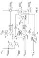
- FIG. 2illustrates an embodiment of an audio system 200 .
- the audio system 200can receive a variable number of inputs 210 and produce a variable number of outputs 280 .
- the audio system 200advantageously enables additional surround speakers to be placed in front of a listener while generating virtual speakers perceived by the listener.
- Various inputs 210are provided to the audio system 200 .
- the number of inputs 210can range from one input to seven inputs.
- inputs ranging from a mono input to a full 6.1 surround set of inputscan be provided.
- a full range of 6.1 surround sound inputs 210are shown in the depicted embodiment, including a left front input 220 , a right front input 222 , a center front input 224 , a subwoofer input 226 , a left surround input 228 , a right surround input 230 , and a center surround input 232 .
- the audio system 200can receive fewer or more inputs 210 than those shown.
- Certain of the inputs 210can include Circle Surround or other matrix surround encoded inputs in some implementations.
- Matrix surround-encoded inputscan be inputs provided by a 5-2-5 matrix surround encoder, which matrix encodes five-channel audio onto two audio channels. These two channels can be efficiently transmitted to a decoder in the audio system, an example of which is described below with respect to FIG. 5 .
- the encoded audiocan be efficiently transmitted to the decoder using any of the popular compression schemes available, such as Mp3, RealAudio, WMA, combinations of the same, and the like.
- the inputs 210can include a single or mono input 210 in some implementations.
- a mono input 210can be provided as the center input 224 in one embodiment.
- a mono-to-stereo conversion module 234can convert the mono input 210 into a stereo signal which is routed to the inputs 220 and 222 .
- the mono-to-stereo conversion module 234in certain embodiments can use the mono-to-stereo conversion techniques described in U.S. patent application Ser. No. 10/734,776, entitled “Systems and Methods of Spatial Image Enhancement of a Sound Source,” filed Dec. 12, 2003, the disclosure of which is hereby incorporated by reference in its entirety.
- the audio system 200can provide a variable number of outputs 280 .
- these outputs 280can include up to a left (front) output 282 , a right (front) output 284 , a center (front) output 286 , a subwoofer output 288 , a left (rear) surround output 290 , and a rear (rear) surround output 292 .
- fewer or more than all the depicted outputs 280 shownare provided by the audio system 200 .
- the number of outputs 280 providedcan be adjusted by a listener.
- the remainder of this specificationwill refer to the inputs 210 and outputs 280 as having input modes and outputs modes, respectively. These input and output modes will be referred to using an “x_y_z” convention, where the “x” refers to the number of front inputs 210 or outputs 280 , the “y” refers to the number of surround inputs 210 or outputs 280 , and the “z” refers to the presence of a subwoofer.
- the input modecould be described as 3 — 2 — 0.
- the output modecould be represented as 2 — 2 — 1.
- Table 1illustrates example input mode configurations available in certain embodiments of the audio system 200 .
- the Tablerefers to the inputs 220 through 232 as L, C, R, Sub, Ls, Cs, and Rs, respectively.
- Table 1also describes a Passive Matrix mode, which provides L t and R t signals.
- the “t” subscriptrefers to “total,” indicating that each L t and R t signal includes encoded information for possibly multiple channels.
- Table 1also describes a 3 — 2_BSDigital mode, which includes signals provided by a BS Digital Broadcaster, which, in certain embodiments, do not include a discretely-encoded center channel.
- Table 1describes a PL2_Music mode for signals decoded with Dolby Pro Logic II and a Circle Surround mode for inputs received from a Circle Surround decoder.
- Input Mode Inputs 210(Channels) 1_0_1 C/Sub 2_0_1 L R/ Sub 2_1_1 L R/Cs/Sub 2_2_1 L R/Ls Rs/Sub 3_0_1 L C R/ Sub 3_1_1 L C R/Cs/Sub (Also for signals decoded with Dolby Pro Logic) 3_2_1 L C R/Ls Rs/Sub (Also for signals decoded with Dolby Pro Logic II in Movie mode) 3_3_1 L C R/Ls Cs Rs/Sub Passive Matrix encoded L t R t signals (e.g., encoded using Circle Surround techniques) 3_2_BSDigital L C R/Ls Rs/Sub PL2_Music L C R/Ls Rs/Sub (For signals decoded with Dolby Pro Logic II in Music mode) Circle Surround L C R/L (s) R (s) /Sub (For signals decoded with Dolby Pro
- Table 2illustrates example output modes available in certain embodiments of the audio system 200 .
- the Tablerefers to the outputs 282 through 292 as L, C, R, Sub, Ls, Cs, and Rs, respectively.
- Output Outputs 280(Channels) Mode Used 2_2_0 L, R, Ls, Rs 2_2_1 L, R, Ls, Rs, Sub 3_2_0 L, R, C, Ls, Rs 3_2_1 L, R, C, Ls, Rs, Sub
- the left input 220 , the right input 222 , and the center input 224are provided to a front signal routing module 240 a .
- the left surround input 228 , the right surround input 230 , and the center surround input 232are provided to a rear signal routing module 240 b .
- the front signal routing module 240 acan include components for combining or routing certain of the front inputs 220 , 222 , and 224 depending on a selected input mode.
- the rear signal routing module 240 bcan include components for combining certain of the inputs 228 , 230 , and 232 depending on the input mode.
- the front and rear signal routing modules 240can further adjust an input gain of the inputs 210 in certain embodiments to increase headroom for further signal processing.
- one or both of the signal routing modules 240can include a passive matrix decoder that decodes Circle Surround inputs. An example passive matrix decoder is shown and described below with respect to FIG. 5 .
- the front signal routing module 240 aprovides a left pre-output 242 , a right pre-output 244 , and a center pre-output 246 to a front surround processing module 250 a .
- the signal routing module 240 bprovides a left surround pre-output 247 , a right surround pre-output 248 , and a center surround pre-output 249 to a rear surround processing module 250 a .
- the front and rear surround processing modules 250include one or more perspective filters that produce or enhance surround sound effects of the pre-outputs 242 through 249 .
- the front and rear surround processing modules 250can also process the subwoofer input 226 in certain embodiments. More detailed embodiments of the surround processing modules 250 are described below with respect to FIGS. 6 and 7 .
- the front processing module 250 aprovides a left post 242 output, a right post output 254 , and a center post output 256 to an output mix module 260 .
- the rear processing module 250 blikewise provides a left surround post output 258 and a right surround post output 259 to the output mix module 260 .
- the output mix module 260includes components for mixing one or more of the post outputs 252 , 254 , and 256 .
- the output mix module 260in certain embodiments also passes the left and right surround post outputs 258 , 259 without mixing these outputs. Additionally, in certain embodiments, the output mix module 260 applies a user-adjustable gain to the left and right surround post outputs 258 , 259 . This user-adjustable gain can be applied to adjust the amount of surround effect provided.
- the output mix module 260provides a left mix output 262 , a right mix output 265 , a center mix output 266 , a subwoofer mix output 268 , a left surround mix output 270 , and a right surround mix output 272 .
- These mix outputs in certain embodimentsare provided as the outputs 280 , which in more detail include outputs 282 , 284 , 286 , 288 , 290 , and 292 , respectively.
- the audio system 300in certain embodiments includes all of the functionality of the audio system 200 .
- the audio system 300includes the inputs 210 , the signal routing modules 240 , the surround processing modules 250 , and the output mix module 260 .
- the audio system 300also provides additional audio enhancement modules including a dialog clarity module 351 , a bass management module 380 , and definition modules 393 .
- the dialog clarity module 351 of certain embodimentsincludes one or more dialog clarity filters for enhancing the clarity of dialog.
- the dialog clarity module 351can beneficially enhance the clarity of dialog found in movies, television shows, other audio and/or audiovisual productions, and the like. Certain implementations of the dialog clarity module 351 enhance dialog by emphasizing formants in speech. An example dialog clarity module 351 is described below with respect to FIG. 10 .
- the dialog clarity module 351can use some or all of the dialog clarification techniques disclosed in U.S. Pat. No. 5,459,813 to Klayman, titled “Public Address Intelligibility System,” issued Oct. 17, 1995, the disclosure of which is hereby incorporated by reference in its entirety.
- the bass management module 300includes a bass enhancer for optionally enhancing low frequency audio information provided on the front mix outputs 262 , 264 , and 266 and/or the subwoofer mix output 268 .
- the bass management module 380can also include a crossover network of filters that can be optionally applied to one or more of the mix outputs 262 through 272 .
- the crossover networkcan be used, for instance, when a subwoofer output 397 is used. This crossover network can apply filters to the mix outputs 262 through 272 to beneficially localize low frequency information on the subwoofer channel.
- the bass enhancement and crossover features of the bass management module 300can be turned on or off by a listener in certain embodiments. Further details of the bass enhancer and crossover network are described with respect to FIGS. 11 and 12 below.
- the bass management module 380passes a subwoofer output 388 , a left surround output 391 , and a right surround output 392 as a subwoofer output 397 , a left surround output 398 , and a right surround output 399 .
- the bass management module 380also optionally passes a left output 382 , a right output 384 and a center output 386 to one or more definition modules 393 .
- the definition modules 393include one or more filters for emphasizing certain high frequency regions of audio signals. These filters can improve the perception of clarity and of acoustic space in the left, right, and/or center outputs 382 , 384 , and 386 .
- One definition module 393can receive all three outputs 382 , 384 , and 386 . Alternatively, as shown, three separate definition modules 393 can each receive an output 382 , 384 , and 386 . More detailed embodiments of the definition module 393 are described below with respect to FIG. 13 .
- the signal routing module 400in one embodiment is an implementation of the front signal routing module 240 a described above with respect to FIGS. 2 and 3 .
- the signal routine module 400includes components for combining or routing certain of the front inputs 220 , 222 , and 224 depending on a selected input mode.
- the signal routing module 400receives the left input 220 , the right input 222 , and the center input 224 . These inputs are each provided to input gain blocks 402 , 404 , and 406 , respectively.
- the input gain blocks 402 , 404 , and 406in various implementations control the signal level of the inputs 220 , 222 , and 224 .
- the input gain blocks 402 , 404 , and 406can, for example, attenuate one or more the signal inputs 220 , 222 , and 224 to provide additional headroom for further processing.
- the input gain blocks 402 , 404 , and 406can have a gain value ranging from 0 to 1.
- An exemplary value of the input gain blocks 402 , 404 , and 406is 0.5, representing a one-half or 6 decibel (dB) attenuation.
- dBdecibel
- the values of the input gain blocks 402 , 404 , and 406are equal in one embodiment but can vary from one another in other embodiments.
- the output of the input gain block 402is provided to sum block 408 .
- the output of the input gain block 404is provided to sum block 410 .
- the output of input gain block 406is provided to switch 412 . If a BS Digital mode is selected, the output of the switch 412 is provided to both sum blocks 408 , 410 .
- the sum block 408then sums the input from the input gain block 402 and the input gain block 406 and provides the left pre output 242 .
- the sum block 410sums the input from the input gain block 404 and the input gain block 406 and provides the left pre output 242 .
- the switch 412passes the output of the input gain block 406 as the center pre output 246 and does not pass an output to the sum blocks 408 and 410 . Accordingly, the sum blocks 408 , 410 pass their respective inputs to the left pre output 242 and the right pre output 244 , respectively.
- FIG. 5illustrates another example embodiment of a signal routing module 500 .
- the signal routing module 500in one embodiment is an implementation of the rear signal routing module 240 b described above with respect to FIGS. 2 and 3 .
- the signal routine module 500includes components for combining or routing certain of the rear inputs 228 , 230 , and 232 depending on a selected input mode.
- the signal routine module 500also includes components for combining or routing the matrix surround-encoded inputs.
- matrix surround-encoded left and right (total) inputs 220 , 222are provided to input gain blocks 506 , 508 respectively, which in certain embodiments include the same functionality of the input gain blocks described above with respect to FIG. 4 .
- the outputs of the input gain blocks 506 and 508are provided to a passive matrix decoder 510 .
- the passive matrix decoderuses these outputs to synthesize a left surround input 516 and a right surround input 518 , which are provided to sum blocks 526 and 530 , respectively.
- the inputs 220 and 222can be used in some non-Circle Surround implementations. For instance, if the input mode includes no surround content (e.g., 2 — 0 — 1 or 3 — 0 — 1), the left and right inputs 220 , 222 can be provided to the respective input gain blocks 506 , 508 , which provide outputs to the passive matrix decoder 510 . The passive matrix decoder 510 can then be used to synthesize the left surround input 516 and the right surround input 518 .
- no surround contente.g., 2 — 0 — 1 or 3 — 0 — 1
- the passive matrix decoder 510can then be used to synthesize the left surround input 516 and the right surround input 518 .
- the left surround input 228 , center surround input 230 , and right surround input 2323are also provided to respective input gain blocks 520 , 522 , and 524 , which can function in the manner described above.
- the output of the input gain block 520is provided to a sum block 526
- the output of the input gain block 522is provided to switch 528
- the output of input gain block 524is provided to a sum block 530 .
- the sum block 526also receives the output of the input gain block 522 .
- the sum block 526sums the output of the input gain block 520 , the output 516 , and optionally the output of the input gain block 522 to produce the left surround pre output 247 .
- the sum block 530also receives the output of the input gain block 522 if the input mode is 3 — 3_x or x — 1_x.
- the sum block 530then sums the output of the input gain block 524 , the output 518 , and optionally the output of the input gain block 522 to produce the right surround pre output 249 .
- the switch 528provides the output of the input gain block 522 as the center surround pre output 248 .
- FIG. 6illustrates an embodiment of a front surround processing module 600 .
- the front surround processing module 600is a more detailed example implementation of the front surround processing module 350 a .
- the front surround processing module 600produce or enhances surround sound effects of the pre-outputs 242 , 244 , and 246 .
- the front surround processing module 600can process the subwoofer input 226 in certain embodiments.
- the front surround processing module 350 areceives the left pre output 242 , the right pre output 244 , the center pre output 246 , and the subwoofer input 226 from a signal routing module.
- the left pre output 242 and the right pre output 244are summed at block 602 and at sum block 604 .
- the output of the sum block 602is provided to a multiply block 610 , which multiplies the output of the sum block 602 with a front space control input 608 .
- the front space control input 608is provided in some implementations for testing and customization purposes.
- the front space control input 608can include a ⁇ 3 to ⁇ 12 dB value in certain embodiments, which effectively reduces the output of the sum block 602 by ⁇ 3 to ⁇ 12 dB. However, other values can be chosen for the front space control input 608 .
- the output of the multiply block 610is provided to a perspective front space module 618 .
- the perspective front space module 618includes one or more perspective filters, which process the output of the multiply block 610 to provide or enhance a front surround sound effect. An embodiment of the perspective front space module is described in greater detail below with respect to FIG. 8 .
- the output of the perspective front space module 618is provided to sum block 630 .
- this output 242is also provided to a gain block 606 , which in the depicted embodiment includes a ⁇ 18 dB attenuation. This value may be varied in other implementations.
- the output of the gain block 606is provided to the sum block 630 .
- the right pre output 244is also provided to a gain block 616 , which in the depicted embodiment also includes a ⁇ 18 dB attenuation. This value also may be varied in other implementations.
- the output of the gain block 616is provided to a sum block 642 .
- the output of the sum block 604is provided to switches 612 and 614 .
- the switches 612 , 614provide the center pre output 246 to multiply block 624 .
- the output of the sum block 604is provided to gain block 620 , which has an example value of ⁇ 20 dB.
- the output of the gain block 620is further provided to a sum block 632 .
- the switches 612 , 614provide the output of the sum block 604 to the multiply block 624 .
- the multiply block 624multiples the center pre output 246 with a front center control input 622 .
- the front center control input 622is provided in some implementations for testing and customization purposes. In certain embodiments, the front center control input 622 has a value of ⁇ 4 dB, although other values may be chosen in other embodiments.
- the output of the multiply block 624is provided to a dialog enhancer module 651 for enhancing dialog on the center pre output 246 or the combined left and right pre outputs 242 , 244 .
- the dialog enhancer module 641can have the same or similar functionality as the dialog enhancer module 351 described above with respect to FIG. 3 .
- a more detailed example implementation of the dialog enhancer module 651is shown in greater detail below with respect to FIG. 10 .
- the output of the dialog enhancer module 651is provided to a gain block 628 , which in the depicted embodiment has an example value of ⁇ 3 dB.
- the output of the gain blockis provided to switch 634 .
- the output of the dialog enhancer 651is also provided directly to switch 634 . If the output mode is 2 — 0_x or 2 — 2_x, then the switch 634 provides the output from the dialog enhancer 351 directly to sum block 632 . If, however, the output mode is neither 2 — 0_x or 2 — 2_x, then the switch 634 instead provides the output of the gain block 628 to the sum block 632 .
- the output of the dialog enhancer module 651is also provided to switch 640 . If the output mode is 3 — 0_x or 3 — 2_x, then the switch 640 provides the output of the dialog enhancer 651 as the center post output 356 . Otherwise, the switch 640 does not pass the output of the dialog enhancer module 651 as the center post output 356 .
- the subwoofer input 226is provided to switch 636 . If Circle Surround mode is not in use, then the output of the switch 636 is provided to switch 638 . Otherwise, the output of the switch 636 is not provided to the switch 638 .
- the switch 638provides an output if the system is not in x_x — 1 output mode.
- the output of the switch 638is provided to sum block 632 , which provides a summed output to the sum block 642 .
- the output of the sum block 642provided as the right post output 354 .
- the output of the sum block 630is the left post output 352 .
- FIG. 7illustrates an embodiment of a rear surround processing module 700 .
- the rear surround processing module 700is a more detailed example implementation of the rear surround processing module 250 b .
- the rear surround processing module 700produce or enhances surround sound effects of the pre-outputs 247 , 248 , and 249 .
- the rear surround processing module 700can process the subwoofer input 226 in certain embodiments.
- the rear surround processing module 250 breceives the left surround pre output 247 , the center surround pre output 248 , the right surround pre output 249 , and the subwoofer input 226 .
- the left surround pre output 247 and the right surround pre output 249are provided to sum block 702 , where the right surround pre output 249 is subtracted from the left surround 247 .
- the output of the sum block 702is provided to a switch 706 . If Circle Surround-encoded inputs are provided, then the switch 706 does not pass the output of the sum block 702 . Otherwise, the switch 706 passes the output of the sum block 702 to a perspective rear space module 708 .
- the perspective rear space module 708includes one or more perspective filters for providing or enhancing a rear surround sound effect. A more detailed example embodiment of the perspective rear space module 708 is described below with respect to FIG. 9 .
- the output of the perspective rear space module 708is provided to multiply block 710 , where it is multiplied with a rear space control input 712 .
- the rear space control input 712is provided in some implementations for testing and customization purposes. Example values for the rear space control input 712 can range from ⁇ 11 dB to +9 dB, depending on input mode used. However, other values and ranges can be used in alternative embodiments.
- the output of the multiply block 710is provided to a multiply block 728 , a multiply block 736 , and a sum block 730 .
- the left and right surround pre outputs 247 , 249are also provided to sum block 704 , where the two outputs 247 , 249 are summed together.
- the output of the sum block 704is provided to switch 714 . If the input mode is 3 — 3_x, then the switch 714 passes the center surround pre output 248 to a perspective rear center module 716 . However, if the input mode is not 3 — 3_x, then the switch 714 instead passes the output of the sum block 704 to the perspective rear center module 716 .
- the perspective rear center module 716in certain embodiments includes the same functionality as the perspective rear space module 708 .
- the output of the perspective rear center module 716is provided to multiply block 718 , which multiplies this output with a rear center control input 720 .
- the rear center control input 720is provided in some implementations for testing and customization purposes.
- the rear center control input 720can have a range of values, such as ⁇ 11 dB to +9 dB, in certain embodiments.
- the output of the multiply block 718is provided to sum block 732 .
- the sum block 732in turn provides an output to sum blocks 730 and 734 .
- the left surround pre output 247is also provided to a gain block 726 .
- the value of the gain block 726 in the depicted embodimentis ⁇ 12 dB, although other values may be chosen.
- the output of the gain block 726is provided to sum block 730 .
- the left surround pre output 247is also provided to multiply block 728 , where the output 247 is multiplied with the output of the multiply block 710 .
- the outputs of both the sum block 730 and the multiply block 728are provided to a switch 740 . If Circle Surround-encoded inputs are used, then the switch 740 passes the output of the multiply block 728 as the left surround post output 258 . Otherwise, switch 740 passes the output of the sum block 730 as the left surround post output 258 .
- the right surround pre output 249is similarly passed to a gain block 738 , which in the depicted embodiment has a ⁇ 12 dB gain, although other values may be chosen.
- the output of the gain block 738is provided to the sum block 734 .
- the right surround pre output block 249is also provided to the multiply block 736 .
- the outputs of the sum block 734 and the multiply block 736are provided to a switch 742 . If Circle Surround-encoded inputs are used, then the switch 742 passes the output of the multiply block 736 as the right surround post output 259 . Otherwise, the switch 742 passes the output of the sum block 734 as the right surround post output 259 .
- the subwoofer input 226is provided to a switch 722 . If Circle Surround-encoded inputs are used, then the output of the switch 722 is passed to the switch 706 . The switch 706 passes this output to the perspective rear space module 708 in place of the output of the sum block 702 if Circle Surround-encoded inputs are used. If Circle Surround-encoded inputs are not used, the output of the switch 722 is instead passed to a switch 724 . If the output mode is x_x — 0 or x_x — 1, then the output of the switch 724 is passed to the sum block 732 . Otherwise, the output of the switch 724 is not passed by the switch 724 .
- FIG. 8illustrates an embodiment of an output mix module 800 .
- the output mix module 800is a more detailed example implementation of the output mix module 260 .
- the output mix module 800includes components for mixing one or more of the post outputs 252 , 254 , and 256 of the audio system 200 , or the post outputs 352 , 354 , and 356 of the audio system 300 .
- the output mix module 800in certain embodiments also passes the left and right surround post outputs 258 , 259 and the subwoofer input 226 without mixing these signals.
- the output mix module 260receives, for example, the left post output 352 , the right post output 354 , the center post output 356 , the subwoofer input 226 , the left surround post output 258 , and the right surround post output 259 .
- the left post output 352is provided to a sum block 802 .
- the sum blockalso receives the output of switch 806 .
- Switch 806receives the center post output 356 .
- the center post output 356is passed by the switch 806 to sum block 802 if the output mode is either 2 — 2_x or 3 — 2_x. Otherwise, the center post output 356 is provided by the switch 806 directly as the center mix output 366 .
- the output of the sum block 802is the left mix output 362 .
- the right post output 354is provided to a sum block 804 .
- Sum block 804likewise receives the output of the switch 806 if the output mode is either 2 — 2_x or 3 — 2_x.
- the output of sum block 804is provided as the right mix output 364 .
- the subwoofer input 226is provided directly as the subwoofer mix output 268 .
- the left surround post output 258is provided to a multiply block 810 and a sum block 808 .
- the multiply block 810multiplies the left surround post output 258 with a surround level control input 812 .
- the surround level control input 812in certain embodiments adjusts the level of rear surround effect provided by an audio system, such as the audio system 200 or 300 .
- the output of the multiply block 810is provided to the sum block 808 , which adds this output with the left surround post output 258 .
- the output of the sum block 808is provided as the left surround mix output 270 .
- the right surround post output 259is provided to a sum block 816 and to a multiply block 814 .
- the multiply block 814multiplies this output 259 with the surround level control input 812 .
- the output of the multiply block 814is provided to the sum block 816 to be summed with the right surround post output 259 .
- the sum block 816provides an output as the right surround mix output 272 .
- FIG. 9Aillustrates an embodiment of front perspective module 900 A, which in certain embodiments represents a more detailed implementation of the perspective front space module 618 .
- the front perspective module 900 Abeneficially includes one or more perspective filters or curves for producing or enhancing a front surround sound effect.
- the front perspective module 900 Ais shown receiving an input sample 901 .
- the input sample 901is provided to a filter 903 .
- the filter 903is a high pass filter having a corner frequency of about 48 hertz (Hz). Other values, however, may be chosen in other embodiments.
- the output of the filter 903is provided to a gain block 905 , a gain block 907 , a filter 909 , and a filter 911 .
- the gain block 905 in the depicted embodimentincludes an example ⁇ 16 dB gain (e.g., attenuation).
- the output of the gain block 905is provided to a switch 913 .
- the gain block 907includes an example ⁇ 6 dB gain.
- the output of the gain block 907is also provided to the switch 814 . If the output mode is set to headphone, then the switch 913 passes the output from the gain block 905 to a sum block 915 . Conversely, if headphones are not used as an output mode, the switch 913 passes the output of gain block 907 to the sum block 915 .
- the filter 909 in the depicted embodimentis a high pass filter having a corner frequency of about 7 kilohertz (kHz). The value of the corner frequency may be varied in certain embodiments.
- the output of the pass filter 909is provided to the sum block 915 .
- the filter 911 in the depicted embodimentis a low pass filter having a corner frequency of about 200 Hz.
- the output of the filter 911is provided to gain blocks 917 and 919 .
- the value of the gain block 917 in certain embodimentsis 5 dB, although this value may be varied.
- the value of the gain block 917is provided to switch 921 .
- the gain block 919has a value of 3 dB in certain embodiments, although this value may also be varied.
- the output of the gain block 919is passed to the switch 921 . If the output mode is set to headphone, then the switch 921 passes the output from the gain block 917 . Otherwise, the switch 921 passes the output from the gain block 919 .
- the output from the switch 921is provided to the sum block 915 , which sums the outputs from the switch 913 , the filter 909 , and the switch 921 to provide an output sample 923 .
- the filters 903 , 909 , and 911are shown separately, their processed output by the sum block 915 comprises a perspective filter curve.
- This perspective filter or curvecan have a different shape or frequency response in head phone mode than in other (“Normal”) modes.
- the terms perspective filter or curve in certain embodimentscan refer to both the combination of the filters 903 , 909 , 911 and to each filter 903 , 909 , 911 separately.
- Example frequency response curves of the combined filters 903 , 909 , and 911are described with respect to FIG. 14 below.
- FIG. 9Billustrates an embodiment of rear perspective module 900 B, which in certain embodiments represents a more detailed implementation of one or both of the perspective rear space and center modules 708 , 716 .
- the rear perspective module 900 Bbeneficially includes one or more perspective filters or curves for producing or enhancing a front surround sound effect.
- the rear perspective filter module 900 Breceives an input sample 902 , which is passed to a filter 904 and a filter 906 .
- the filter 904in certain embodiments, is a high pass filter, with a corner frequency of about 13 kHz. This value may be varied in certain embodiments.
- the output of the filter 904is passed to a filter 908 , which is a low pass filter having a corner frequency of 8 kHz in certain embodiments.
- the output of the filter 908is passed to a gain block 910 , which has a value of 0.665 (no units). This value may also be varied in certain embodiments.
- the output of the gain block 910is provided to sum block 914 .
- the filter 906in certain embodiments, is a low pass filter having an example corner frequency of 950 Hz.
- the output of the filter 906is provided to a gain block 912 , which includes an example value of 0.34 (no units).
- the output of the gain block 912is provided to the sum block 914 , which sums the output of the gain block 912 and the output of the gain block 910 to produce an output sample 916 .
- the filters 904 , 906 , 908are shown separately, their processed output by the sum block 914 comprises a perspective filter curve.
- the terms perspective filter or curve in certain embodimentscan refer to both the combination of the filters 904 , 906 , 908 and to each filter 904 , 906 , 908 separately.
- FIG. 10illustrates an embodiment of a dialog clarity module 1000 , which in certain embodiments represents a more detailed implementation of the dialog clarity modules 351 , 651 described above.
- the dialog clarity module 1000receives an input sample 1002 .
- the input sample 1002is provided to a gain block 1004 and to a filter 1006 .
- the value of the gain block 1004is 0 dB.
- the gain block 1004comprises a default bypass gain.
- the output of the gain block 1004is provided to switch 1014 . If dialog clarity is enabled, then the switch 1014 does not pass the output of the gain block 1004 . However, if dialog clarity is disabled, then the output of the gain block 1004 , which in certain embodiments is the same or substantially the same as the input sample 1002 , is passed by the switch 1014 to the output 1016 . Dialog clarity can be enabled or disabled, for example, by a listener.
- the filter 1006is a high pass filter in certain embodiments, having a corner frequency of about 723 hertz, although this value may be varied.
- a transfer function H(z) describing the filter 1006is given by:
- H ⁇ ( z )b 0 + b 1 ⁇ z - 1 1 - az - 1 , where a, b 0 , and b 1 represent filter coefficients, and where z represents an independent complex variable.
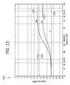
- Example frequency response curves associated with the filter 1006are described below with respect to FIG. 15 .
- the output of the high pass filteris provided to a multiply block 1010 which receives a dialog clarity control input 1008 .
- the dialog clarity control input 1008has a value from 0 to 1.
- the dialog clarity control input 1008can determine the amount of dialog clarity enhancement that is applied to the input signal 1002 .
- the dialog clarity enhancementhas a value of 0.5. However, other ranges and values also may be used.
- the multiply block 1010multiplies the dialog clarity control input 1008 with the output of the filter 1006 to produce an output which is provided to sum block 1012 .
- Sum block 1012sums the input sample 1002 with the output of the multiply block 1010 and provides an output to the switch 1014 . If the switch 1014 is enabled, then the switch 1014 passes the output from the sum block 1012 as the output sample 1016 .
- FIG. 11illustrates an example embodiment of a bass management network 1100 .
- the bass management network 1100represents a more detailed embodiment of the bass management network 380 described above.
- the bass management network 1100can enhance bass responses on subwoofer and non-subwoofer audio channels.
- the bass management network 1000in certain embodiments includes bass enhancers 1120 a and 1120 b .
- the bass enhancers 1120can enhance audio frequencies associated with a bass output.
- the bass management network 380includes an optional crossover network, which includes one or more of filters 1126 , 1128 , 1130 , 1118 , 1122 , and 1136 .
- this crossover networkenables bass frequencies to be localized in the subwoofer output 388 in some implementations where the subwoofer output 388 is used.
- Certain embodiments of frequency responses for the filters 1126 , 1128 , 1130 , 1118 , 1122 , and 1136are described below with respect to FIG. 17 .
- the bass management system 1000receives a left mix output 262 , a right mix output 264 , a center mix output 266 , a subwoofer mix output 268 , a left surround mix output 270 , and a right surround mix output 272 from the output mix module 260 .
- the left mix output 262is provided to switch 1102 . If a bass enhancer 1120 a is to be turned off, for example, by a listener, the switch 1102 passes the left mix output 262 to switch 1104 . If a subwoofer is not provided on the output (e.g., output mode is x_x — 0), then the switch 1104 passes the left mix output 262 as the left output 382 .
- the switch 1102passes the left mix output 262 to the bass enhancer 1120 a .
- the bass enhancer 1120 aprocesses the left mix output 262 to enhance the bass response of selected low frequencies and passes an output as the left output 382 and an output as the right output 384 . Further details of an example bass enhancer 1120 a are described below with respect to FIG. 12 .
- the bass enhancer 1120 a(and the bass enhancer 1120 b ) can, in certain embodiments, use some or all of the bass enhancement techniques disclosed in U.S. Pat. No. 6,285,767 to Klayman, titled “Low-Frequency Audio Enhancement System,” issued Sep. 4, 2001, the disclosure of which is hereby incorporated by reference in its entirety.
- the switch 1104passes the left mix output 262 to the filter 1126 .
- the filter 1126is part of the crossover network and is used in certain embodiments when the subwoofer output 388 is present (e.g., during x_x — 1 output modes).
- the crossover network filters, including the filter 1126need not be used in every case where the subwoofer output 388 is used.
- the filter 1126is a high pass filter in the depicted embodiment, having a configurable corner frequency from a range of about 80 to about 200 hertz.
- the corner frequencyin one embodiment, can be selected by a listener. In another embodiment, the corner frequency is hard-coded into the bass management module 380 . Other ranges or values for the corner frequency can be chosen in certain embodiments.
- the filter 1126removes the low frequency components in the left mix output 262 and thereby facilitates localizing the low frequency components on the subwoofer output 388 .
- the output of the filter 1126is provided as the left output 382 .
- the right mix output 264is provided to a switch 1108 . If the bass enhancer 1120 a is to be turned off, for example by a listener, the switch 1108 passes the right mix output 264 to the switch 1110 . If the output mode is x_x — 1, the switch 1110 passes the right mix output 264 as the right output 384 . If, however, the bass enhancer is to be turned on, then the switch 1108 passes the right mix output 264 to the bass enhancer 1120 a , which in turn passes an output as the right output 384 and an output as the left output 382 .
- the switch 1110passes the right mix output 264 to the filter 1128 .
- the filter 1128incorporates some or all of the same functionality as the filter 1126 .
- the filter 1128provides the right output 384 .
- the center mix output 266is passed to a switch 1112 . If the output mode is 3 — 2_x, the switch 1112 passes the center mix output 266 to switch 1114 . Otherwise, the switch 1112 does not pass the center mix output 266 .
- the switch 1114passes the center mix output 266 as the center output 386 if the output mode is x_x — 1. However, if the output mode is x_x — 0, the switch 1114 passes the center mix output 266 to the filter 1130 .
- the filter 1130has the same or some of the same functionality as filters 1126 .
- the output of the filter 1130is provided as the center output 386 .
- the subwoofer mix output 268is passed to the switch 1116 . If the output mode is x_x — 1, then the switch 1116 passes the subwoofer mix output 268 to the filter 1118 and to a subwoofer bass enhancer 1120 b . Otherwise, the switch 1116 does not pass the subwoofer mix output 268 .
- the filter 1118in certain embodiments, is a low pass filter having a corner frequency of about 80 to 200 hertz. In one embodiment, the corner frequency of the filter 1118 is set to be equal to the corner frequencies of filters 1126 , 1128 , and 1130 .
- the filters 1118 , 1126 , 1128 , 1130 and as described below 1134 and 1136facilitate localizing the bass or low frequency components of an audio signal on the subwoofer.
- the signal from the switch 1116is also passed to the subwoofer bass enhancer 1120 b , which enhances the low frequency components of the bass signal.
- the output of the filter 1118is provided to switch 1132 and the output of the subwoofer bass enhancer 1120 b is provided to switch 1132 . If the sub bass enhancer is selected to be turned on, for example by a listener, then the switch 1132 passes the output of the sub bass enhancer 1120 b but not the output of the filter 1118 . Otherwise, if the sub crossover network is selected to be turned on, for example by a user, then the output of the filter 1118 is passed by the switch 1132 and the switch 1132 does not pass the output of the subwoofer bass enhancer 1120 b .
- the output of the switch 1132is passed as the subwoofer output 388 .
- the left surround mix output 270is passed to a switch 1122 . If the output mode is x_x — 1, then the switch passes the left surround mix output 270 to the filter 1134 , which in certain embodiments includes some or all of the functionality of the filter 1126 . The output of the filter 1134 is provided as the left surround input 391 . Alternatively, if the output mode is x_x — 0, the switch 1122 provides the left surround mix output 270 directly as the left surround output 391 .
- the right surround mix output 272is provided to a switch 1124 . If the output mode is x_x — 1, the switch 1124 passes the right surround mix output 272 to a filter 1136 , which in certain embodiments includes some or all of the functionality of the filter 1126 . The filter 1136 provides an output which is the right surround output 392 . Otherwise, if output mode x_x — 0 is selected, the switch 1124 passes the right surround mix 272 directly as right surround output 392 .
- FIG. 12illustrates an example bass enhancer 1200 .
- the bass enhancer 1200in certain embodiments can be a more detailed implementation of the bass enhancer 1120 a and/or 1200 b described above.
- the bass enhancer 1200can enhance audio frequencies associated with a bass output. Example frequency responses generated by the bass enhancer 1200 are described below with respect to FIG. 16 .
- the bass enhancer 1200is shown in the depicted embodiment receiving a left input 1202 (e.g., a sample) and a right input 1204 (e.g., a sample). Both the left and the right inputs 1202 and 1204 are provided to default bypass gain blocks 1201 and 1246 , respectively.
- the default bypass gain blocks 1201 and 1246each have 0 dB gain such that if the bass enhancer 1200 is bypassed, then the left input 1202 and the right input 1204 are passed directly to the left output 1252 and the right output 1254 , respectively.
- a switch 1248 and a switch 1250respectively determine whether the bass enhancer 1200 is to be bypassed.
- the left input 1202is also passed to a sum block 1208 and to a sum block 1206 .
- the right input 1204is passed to a sum block 1202 and to the sum block 1206 .
- the output of the sum block 206is a combined output of the sum of the left inputs 1202 and the right input 1204 .
- the output of the sum block 1206is provided to a low pass filter 1210 .
- the output of the low pass filteris provided to the sum block 1208 and to another low pass filter 1214 .
- the output of the low pass filter 1210is provided to a sum block 1212 .
- the sum block 1208subtracts the input received from the low pass filter 1210 from the left input 1202 and provides an output to a sum block 1242 .
- the sum block 1212subtracts the low pass filter 1210 output from the right input 1204 and provides an output to the sum block 1244 .
- the low pass filter 1214provides outputs to a multiply block 1236 , to a first band pass filter 1216 , and to a second band pass filter 1218 .
- the cutoff frequencies of the low-pass filters 1210 and the band-pass filters' 1216 , 1218 center frequenciescan be adjusted to match the frequency response of speakers being used with an audio system.
- a speaker size selector input 1220is provided to the first band pass filter 1216 and the second band pass filter 1218 .
- speaker size selector input 1220can be selected so that the lowest of the band-pass center frequencies is just above the low cutoff frequency of the speaker system.
- An example table of center and corner frequencies of the filters 1216 , 1218 , 1210 according to the speaker size selector input 1220is provided in the following Table 3:
- the outputs of the band pass filters 1216 and 1218are provided to a sum block 1222 .
- the sum block 1222adds the additive inverse of the output of each band pass filter 1216 , 1218 such that the output of each band pass filter 1216 , 1218 is inverted and then added by the sum block 1222 .
- the output of the sum block 1222is provided to a multiply block 1230 and to an absolute value block 1224 .
- the absolute value block 1224takes the absolute value of the input and provides a rectified output to a fast attack slow decay (FASD) module 1226 .
- the FASD module 1226in certain embodiments detects peaks in the output of the absolute value block 1224 .
- the FASD module 1226can be used, for example, to control attack and release times of the bass enhancer 1200 .
- the output of the FASD module 1226is provided to an integration module 1228 , which provides an integrated output to the multiply block 1230 and to a bass enhancer control 1240 .
- the multiply block 1230provides an output to sum block 1232 .
- the multiply block 1236supplies an output to the sum block 1232 .
- the multiply block 1236receives a mix gain input 1234 , which in certain embodiments provides a flatter frequency response of the bass enhancer 1200 when the bass enhancer control 1240 is turned to a minimum setting.
- the output of the sum block 1232is provided to multiply block 1238 which also receives the bass enhancer control input 1240 .
- the bass enhancer control input 1240specifies the amount of bass enhancement provided to the input signals 1202 , 1204 .
- the bass enhancer control input 1240ranges from 0 to 1. However, other ranges may be used.
- the output of the multiply block 1238is provided to both the sum blocks 1242 and 1244 .
- the output of the sum block 1244is provided to the switch 1248 , which is passed to the left output 1252 if bypass is not enabled.
- the output of the sum block 1244is provided to the switch 1250 , which passes the output of the sum block 1244 as right output 1254 if the bypass is not enabled.
- a definition module 1300is shown.
- the definition module 1300represents a more detailed implementation of one or more of the definition modules 393 described above.
- perceptual coding techniques used in digital compression, and audio processing technology used in broadcast transmission pathscan reduce the clarity of reproduced audio.
- the definition module 1300therefore can improve the perception of clarity and acoustic space in certain embodiments.
- the definition module 1300receives an input sample 1302 which is provided to a default bypass gain block 1304 and to a definition filter 1308 .
- the input sample 1302is provided to a sum block 1314 .
- the default bypass gain block 1304has a 0 dB gain and therefore does not amplify or does not substantially amplify or attenuate the input sample 1302 .
- the output of the default bypass gain block 1304is provided to a switch 1306 . If definition control is enabled, for example, by a user, the switch 1306 does not pass the output of the default bypass gain 1304 . However, if definition control is disabled, the switch 1306 passes the output of the default bypass gain block 1304 as the output sample 1316 .
- the definition filter 1308in certain embodiments processes the input sample 1302 to emphasize certain high frequency regions of the input sample 1302 .
- An example frequency response of the definition filter 1308is described below with respect to FIGS. 18 and 19 .
- the definition filter 1308outputs the process sample to multiplier block 1310 which also receives the definition control signal 1312 .
- the definition control signal 1312can determine the amount of definition control provided to the input sample 1302 .
- the range of values the definition control signal 1312 hasis from 0 to 1. However, other ranges may be used.
- the multiplier block 1310provides an output to a sum block 1314 which provides an output to the switch 1306 . If definition control is enabled, then the switch 1306 passes the output of the sum block 1314 as the output 1316 .
- FIGS. 14 through 19illustrate graphs of example embodiments of some or all of the filters described above.
- the graphsare plotted on a logarithmic frequency scale and an amplitude scale which is measures in dBFS, or decibels full scale. While phase graphs are not shown, in certain embodiments each respective graph has a corresponding phase graph.
- different graphsmay have different magnitude scales reflecting that different filters may have different amplitudes, so as to emphasize certain components of sound and de-emphasize others.
- each graphis shown having an input.
- FIG. 14depicts an input 1402
- FIG. 15depicts an input 1502
- the input in certain embodimentsis a ⁇ 15 dBFSs input that is swept across the entire, or substantially entire, audible frequency range, from 20 Hz to 20 kHz.
- Each graphalso includes one or more traces.
- FIG. 14includes traces 1404 , 1406 , and 1408 .
- the tracesshow an example magnitude response of the filter over the displayed frequency range.
- While the responses show by the traces in FIGS. 14 through 19are shown throughout the entire 20 Hz to 20 kHz frequency range, these response in certain embodiments need not be provided through the entire audible range.
- certain of the frequency responsescan be truncated to, for instance, a 40 Hz to 10 kHz range with little or no loss of functionality. Other ranges may also be provided for the frequency responses.
- a graph 1400is shown which illustrates traces 1404 , 1406 and 1408 .
- the traces 1404 , 1406 and 1408illustrate example frequency responses of one or more of the perspective filters described above, such as the front and or rear perspective filters.
- the trace 1404represents an example embodiment where a surround level setting is set to 0%.
- Trace 1406is an example embodiment where a surround level setting is set to 50%
- trace 1408is an example trace where the surround level is set to 100%.
- the trace 1404starts at about ⁇ 16 dBFS at about 20 Hz, and increases to about ⁇ 11 dBFS at about 100 Hz. Thereafter, the trace 1404 decreases to about ⁇ 17.5 dBFS at about 2 kHz and thereafter increases to about ⁇ 12.5 dBFS at about 15 kHz.
- the trace 1406starts at about ⁇ 14 dBFS at about 20 Hz, and it increases to about ⁇ 10 dBFS at about 100 Hz, and decreases to about ⁇ 16 dBFS at about 2 kHz, and increases to about ⁇ 11 dBFS at about 15 kHz.
- the trace 1408starts at about ⁇ 12.5 dBFS at about 20 Hz, and increases to about ⁇ 9 dBFS at about 100 Hz, and decreases to about ⁇ 14.5 dBFS at about 2 kHz, and increases to about ⁇ 10.2 dBFS at about 15 kHz.
- frequencies in about the 2 kHz rangeare de-emphasized by the perspective filter, and frequencies at about 100 Hz and about 15 kHz are emphasized by the perspective filters. These frequencies may be varied in certain embodiments.
- FIG. 15illustrates an example graph of a frequency response or responses of an example dialog clarity filter.
- the frequency responsesinclude two example responses illustrated by traces 1506 and 1508 .
- the frequency responses illustrated by traces 1506 and 1508comprise high pass filters because the frequency responses emphasize higher frequencies and de-emphasize lower frequencies.
- the trace 1504represents a 0% level of dialog clarity.
- the trace 1506represents a 50% level of dialog clarity.
- the trace 1508represents a 100% level of dialog clarity.
- the trace 1504is about ⁇ 22.5 dBFS for the entire audible frequency spectrum.
- the trace 1506starts at about ⁇ 22.5 dBFS at about 20 Hz and increases to about ⁇ 17 dBFS at about 2 kHz.
- the trace 1508starts at about ⁇ 22.5 dBFS at about 20 Hz and increases to about ⁇ 14 dBFS at about 2 kHz.
- FIG. 16illustrates an example graph 1600 showing embodiments of traces 1604 and 1606 .
- the traces 1604 and 1606illustrate example frequency responses of front and subwoofer bass enhancers, which in an embodiment, are the same bass enhancer implemented with different frequency responses of the respective filters.
- the trace 1604starts at about ⁇ 18 dBFS at about 20 Hz and increases to about ⁇ 11 dBFS at about 55 Hz, and thereafter decreases to less than ⁇ 40 dBFS at about 300 Hz.
- the trace 1606starts at about ⁇ 9 dBFS at about 20 Hz and increases to about ⁇ 6.2 dBFS at about 60 Hz, and decreases to about ⁇ 23 dBFS at about 400 Hz.
- the curves shown by traces 1604 and 1606illustrate traces or frequency responses of a bass enhancer for a speaker with a 60 Hz cutoff frequency. Different frequency responses may be provided for other speakers having different cutoff frequencies.
- FIG. 17illustrates an example graph 1700 which depicts an embodiment of filters used in a crossover network, such as the crossover networks described above.
- the frequency responses of two example filtersare shown, including a frequency response represented by trace 1704 and a frequency response represented by trace 1706 .
- the frequency response represented by trace 1704corresponds to a crossover network filter applied to a subwoofer
- the trace 1706represents a frequency response of a crossover network filter applied to front left and/or right speakers.
- the trace 1704starts at about ⁇ 22.5 dBFS at about 20 Hz and falls off to about ⁇ 40 dBFS at about 220 Hz.
- the corner frequency for the trace 1704is about 60 Hz.
- the trace 1706starts at about ⁇ 40 dBFS at about 30 Hz and increases to about ⁇ 23 dBFS at about 200 Hz.
- the trace 1704 and the trace 1706illustrates that the crossover network filters out low frequencies on the non-subwoofer channels and filters out high frequencies on the subwoofer channel, thereby localizing a bass response on the subwoofer channel.
- FIG. 18illustrates an example graph 1800 that shows an embodiment of the definition filter frequency responses.
- Three frequency responsesare shown represented by traces 1804 , 1806 , and 1808 .
- the trace 1804illustrates a definition amount of about 0%.
- the trace 1806illustrates a definition amount of about 50%.
- the trace 1808illustrates a definition amount of about 100%.
- the trace 1804is about ⁇ 22.5 dBFS for the entire frequency range shown.
- the trace 1806starts at about ⁇ 22.5 dBFS, decreases to about ⁇ 23.5 dBFS at about 400 kHz, and increases to about ⁇ 13 dBFS at about 10 kHz.
- the trace 1808starts similarly at about ⁇ 22.5 dBFS and decreases to about ⁇ 24.5 dBFS at about 400 Hz, and increases to about ⁇ 8.7 dBFS at about 10 kHz.
- the traces shown in the graph 1900are applied to the front left and front right outputs, e.g. using the definition modules 393 a and 393 b.
- FIG. 19illustrates a graph 1900 that depicts example embodiments of frequency responses of a definition filter, such as the definition filter 393 c applied to the front center output in the audio system 300 .
- the definition filter frequency responses showninclude 3 frequency responses represented by traces 1904 , 1906 and 1908 which correspond to values of definition control of 0%, 50%, and 100% respectively.
- the trace 1904is about ⁇ 24 dBFS throughout the entire frequency spectrum.
- the trace 1906starts at about ⁇ 24 dBFS at about 20 Hz, decreases to about ⁇ 23 dBFS at about 400 Hz, and increases to about ⁇ 14.5 dBFS at about 10 kHz
- the trace 1908starts at about ⁇ 24 dBFS at about 20 Hz and decreases to about ⁇ 26 dBFS at about 400 Hz, and increases to about ⁇ 10 dBFS at about 10 kHz.
- acts, events, or functions of any of the methods described hereincan be performed in a different sequence, may be added, merged, or left out all together (e.g., not all described acts or events are necessary for the practice of the method).
- acts or eventsmay be performed concurrently, e.g., through multi-threaded processing, interrupt processing, or multiple processors, rather than sequentially.
- DSPdigital signal processor
- ASICapplication specific integrated circuit
- FPGAfield programmable gate array
- a general purpose processormay be a microprocessor, but in the alternative, the processor may be any conventional processor, controller, microcontroller, or state machine.
- a processormay also be implemented as a combination of computing devices, e.g., a combination of a DSP and a microprocessor, a plurality of microprocessors, one or more microprocessors in conjunction with a DSP core, or any other such configuration.
- a software modulemay reside in RAM memory, flash memory, ROM memory, EPROM memory, EEPROM memory, registers, hard disk, a removable disk, a CD-ROM, or any other form of storage medium known in the art.
- An exemplary storage mediumis coupled to the processor such the processor can read information from, and write information to, the storage medium.
- the storage mediummay be integral to the processor.
- the processor and the storage mediummay reside in an ASIC.
- the ASICmay reside in a user terminal.
- the processor and the storage mediummay reside as discrete components in a user terminal.
Landscapes
- Physics & Mathematics (AREA)
- Engineering & Computer Science (AREA)
- Acoustics & Sound (AREA)
- Signal Processing (AREA)
- Stereophonic System (AREA)
Abstract
Description
| TABLE 1 |
| Input Modes |
| Input Mode | Inputs 210 (Channels) | ||
| 1_0_1 | C/Sub | ||
| 2_0_1 | L R/ | ||
| Sub | |||
| 2_1_1 | L R/Cs/Sub | ||
| 2_2_1 | L R/Ls Rs/Sub | ||
| 3_0_1 | L C R/ | ||
| Sub | |||
| 3_1_1 | L C R/Cs/Sub | ||
| (Also for signals | |||
| decoded with Dolby | |||
| Pro Logic) | |||
| 3_2_1 | L C R/Ls Rs/Sub | ||
| (Also for signals | |||
| decoded with Dolby | |||
| Pro Logic II in Movie | |||
| mode) | |||
| 3_3_1 | L C R/Ls Cs Rs/Sub | ||
| Passive Matrix encoded | LtRt | ||
| signals (e.g., encoded | |||
| using Circle Surround | |||
| techniques) | |||
| 3_2_BSDigital | L C R/Ls Rs/Sub | ||
| PL2_Music | L C R/Ls Rs/Sub | ||
| (For signals decoded | |||
| with Dolby Pro Logic II | |||
| in Music mode) | |||
| Circle Surround | L C R/L(s)R(s)/Sub | ||
| (For signals decoded | |||
| with Circle Surround) | |||
| TABLE 2 |
| Output Modes |
| Output | Outputs 280 (Channels) | ||
| Mode | Used | ||
| 2_2_0 | L, R, Ls, Rs | ||
| 2_2_1 | L, R, Ls, Rs, Sub | ||
| 3_2_0 | L, R, C, Ls, Rs | ||
| 3_2_1 | L, R, C, Ls, Rs, Sub | ||
where a, b0, and b1represent filter coefficients, and where z represents an independent complex variable. In certain embodiments, a Transposed Direct Form II implementation of this transfer function can be provided as follows, with b=b0=−b1:
y[n]=y[n−1]+bx[n]
y[n−1]=−bx[n]+ay[n],
where n represents an independent variable, x[n] represents an input signal as a function of n, and y[n] represents an output signal as a function of n. Example frequency response curves associated with the
| TABLE 3 |
| Example Speaker Size Selector Guidelines |
| Speaker | |||||
| Cutoff | Band Pass Filter Center | ||||
| Frequency | Frequencies | Low Pass Filter | |||
| 40 Hz | 40 Hz | 70 Hz | 40 Hz | ||
| 60 Hz | 61 Hz | 105 Hz | 60 | ||
| 100 Hz | 101 Hz | 175 Hz | 100 Hz | ||
| 150 Hz | 151 Hz | 263 Hz | 150 Hz | ||
| 200 Hz | 202 Hz | 351 Hz | 200 Hz | ||
| 250 Hz | 252 Hz | 439 Hz | 250 Hz | ||
| 300 Hz | 315 Hz | 462 Hz | 300 Hz | ||
| 400 Hz | 420 Hz | 568 Hz | 400 Hz | ||
Claims (20)
Priority Applications (1)
| Application Number | Priority Date | Filing Date | Title |
|---|---|---|---|
| US13/964,885US9232312B2 (en) | 2006-12-21 | 2013-08-12 | Multi-channel audio enhancement system |
Applications Claiming Priority (4)
| Application Number | Priority Date | Filing Date | Title |
|---|---|---|---|
| US87624806P | 2006-12-21 | 2006-12-21 | |
| US11/963,679US8050434B1 (en) | 2006-12-21 | 2007-12-21 | Multi-channel audio enhancement system |
| US13/286,082US8509464B1 (en) | 2006-12-21 | 2011-10-31 | Multi-channel audio enhancement system |
| US13/964,885US9232312B2 (en) | 2006-12-21 | 2013-08-12 | Multi-channel audio enhancement system |
Related Parent Applications (1)
| Application Number | Title | Priority Date | Filing Date |
|---|---|---|---|
| US13/286,082ContinuationUS8509464B1 (en) | 2006-12-21 | 2011-10-31 | Multi-channel audio enhancement system |
Publications (2)
| Publication Number | Publication Date |
|---|---|
| US20140044288A1 US20140044288A1 (en) | 2014-02-13 |
| US9232312B2true US9232312B2 (en) | 2016-01-05 |
Family
ID=44839641
Family Applications (3)
| Application Number | Title | Priority Date | Filing Date |
|---|---|---|---|
| US11/963,679Active2030-08-30US8050434B1 (en) | 2006-12-21 | 2007-12-21 | Multi-channel audio enhancement system |
| US13/286,082Active2028-02-09US8509464B1 (en) | 2006-12-21 | 2011-10-31 | Multi-channel audio enhancement system |
| US13/964,885Active2028-08-27US9232312B2 (en) | 2006-12-21 | 2013-08-12 | Multi-channel audio enhancement system |
Family Applications Before (2)
| Application Number | Title | Priority Date | Filing Date |
|---|---|---|---|
| US11/963,679Active2030-08-30US8050434B1 (en) | 2006-12-21 | 2007-12-21 | Multi-channel audio enhancement system |
| US13/286,082Active2028-02-09US8509464B1 (en) | 2006-12-21 | 2011-10-31 | Multi-channel audio enhancement system |
Country Status (1)
| Country | Link |
|---|---|
| US (3) | US8050434B1 (en) |
Families Citing this family (24)
| Publication number | Priority date | Publication date | Assignee | Title |
|---|---|---|---|---|
| US8050434B1 (en)* | 2006-12-21 | 2011-11-01 | Srs Labs, Inc. | Multi-channel audio enhancement system |
| KR101624904B1 (en) | 2009-11-09 | 2016-05-27 | 삼성전자주식회사 | Apparatus and method for playing the multisound channel content using dlna in portable communication system |
| WO2012042905A1 (en)* | 2010-09-30 | 2012-04-05 | パナソニック株式会社 | Sound reproduction device and sound reproduction method |
| US9154897B2 (en) | 2011-01-04 | 2015-10-06 | Dts Llc | Immersive audio rendering system |
| US8737645B2 (en) | 2012-10-10 | 2014-05-27 | Archibald Doty | Increasing perceived signal strength using persistence of hearing characteristics |
| US9363603B1 (en) | 2013-02-26 | 2016-06-07 | Xfrm Incorporated | Surround audio dialog balance assessment |
| US9084047B2 (en) | 2013-03-15 | 2015-07-14 | Richard O'Polka | Portable sound system |
| US10149058B2 (en) | 2013-03-15 | 2018-12-04 | Richard O'Polka | Portable sound system |
| DE102013007689B4 (en)* | 2013-05-03 | 2016-01-21 | Iav Gmbh Ingenieurgesellschaft Auto Und Verkehr | Method for operating an audio system in a vehicle and audio system in a vehicle |
| WO2014190140A1 (en) | 2013-05-23 | 2014-11-27 | Alan Kraemer | Headphone audio enhancement system |
| US9036088B2 (en) | 2013-07-09 | 2015-05-19 | Archibald Doty | System and methods for increasing perceived signal strength based on persistence of perception |
| EP2830332A3 (en)* | 2013-07-22 | 2015-03-11 | Fraunhofer-Gesellschaft zur Förderung der angewandten Forschung e.V. | Method, signal processing unit, and computer program for mapping a plurality of input channels of an input channel configuration to output channels of an output channel configuration |
| USD740784S1 (en) | 2014-03-14 | 2015-10-13 | Richard O'Polka | Portable sound device |
| WO2016019130A1 (en) | 2014-08-01 | 2016-02-04 | Borne Steven Jay | Audio device |
| UA120372C2 (en) | 2014-10-02 | 2019-11-25 | Долбі Інтернешнл Аб | Decoding method and decoder for dialog enhancement |
| RU2673390C1 (en)* | 2014-12-12 | 2018-11-26 | Хуавэй Текнолоджиз Ко., Лтд. | Signal processing device for amplifying speech component in multi-channel audio signal |
| WO2016133988A1 (en)* | 2015-02-19 | 2016-08-25 | Dolby Laboratories Licensing Corporation | Loudspeaker-room equalization with perceptual correction of spectral dips |
| KR102423753B1 (en) | 2015-08-20 | 2022-07-21 | 삼성전자주식회사 | Method and apparatus for processing audio signal based on speaker location information |
| US9607626B1 (en)* | 2016-03-28 | 2017-03-28 | Amazon Technologies, Inc. | Dynamically reconfigurable filter bank |
| WO2018151858A1 (en)* | 2017-02-17 | 2018-08-23 | Ambidio, Inc. | Apparatus and method for downmixing multichannel audio signals |
| US11528574B2 (en) | 2019-08-30 | 2022-12-13 | Sonos, Inc. | Sum-difference arrays for audio playback devices |
| US11304005B2 (en)* | 2020-02-07 | 2022-04-12 | xMEMS Labs, Inc. | Crossover circuit |
| WO2021252795A2 (en) | 2020-06-11 | 2021-12-16 | Dolby Laboratories Licensing Corporation | Perceptual optimization of magnitude and phase for time-frequency and softmask source separation systems |
| KR20250083799A (en)* | 2023-12-01 | 2025-06-10 | 삼성전자주식회사 | Electronic device and controlling method of electronic device |
Citations (305)
| Publication number | Priority date | Publication date | Assignee | Title |
|---|---|---|---|---|
| US1616639A (en) | 1921-06-03 | 1927-02-08 | Western Electric Co | High-frequency sound-transmission system |
| US1951669A (en) | 1931-07-17 | 1934-03-20 | Ramsey George | Method and apparatus for producing sound |
| US2062275A (en) | 1931-12-14 | 1936-11-24 | Emi Ltd | Sound-transmission, sound-recording, and sound-reproducing system |
| US2113976A (en) | 1934-11-22 | 1938-04-12 | Louis A De Bosa | Pseudo-extension of frequency bands |
| US2315248A (en) | 1940-07-30 | 1943-03-30 | Rosa Louis A De | Pseudo-extension of frequency bands |
| US2315249A (en) | 1941-10-08 | 1943-03-30 | Rosa Louis A De | Pseudo-extension of frequency bands |
| US2461344A (en) | 1945-01-29 | 1949-02-08 | Rca Corp | Signal transmission and receiving apparatus |
| US3170991A (en) | 1963-11-27 | 1965-02-23 | Glasgal Ralph | System for stereo separation ratio control, elimination of cross-talk and the like |
| US3180936A (en) | 1960-12-01 | 1965-04-27 | Bell Telephone Labor Inc | Apparatus for suppressing noise and distortion in communication signals |
| FI35014A (en) | 1962-12-13 | 1965-05-10 | sound system | |
| US3229038A (en) | 1961-10-31 | 1966-01-11 | Rca Corp | Sound signal transforming system |
| US3246081A (en) | 1962-03-21 | 1966-04-12 | William C Edwards | Extended stereophonic systems |
| BE674341A (en) | 1965-01-22 | 1966-04-15 | ||
| US3249696A (en) | 1961-10-16 | 1966-05-03 | Zenith Radio Corp | Simplified extended stereo |
| JPS4312585Y1 (en) | 1965-12-17 | 1968-05-30 | ||
| US3398810A (en) | 1967-05-24 | 1968-08-27 | William T. Clark | Locally audible sound system |
| US3612211A (en) | 1969-07-02 | 1971-10-12 | William T Clark | Method of producing locally occurring infrasound |
| US3665105A (en) | 1970-03-09 | 1972-05-23 | Univ Leland Stanford Junior | Method and apparatus for simulating location and movement of sound |
| US3697692A (en) | 1971-06-10 | 1972-10-10 | Dynaco Inc | Two-channel,four-component stereophonic system |
| US3725586A (en) | 1971-04-13 | 1973-04-03 | Sony Corp | Multisound reproducing apparatus for deriving four sound signals from two sound sources |
| US3745254A (en) | 1970-09-15 | 1973-07-10 | Victor Company Of Japan | Synthesized four channel stereo from a two channel source |
| US3757047A (en) | 1970-05-21 | 1973-09-04 | Sansui Electric Co | Four channel sound reproduction system |
| US3761631A (en) | 1971-05-17 | 1973-09-25 | Sansui Electric Co | Synthesized four channel sound using phase modulation techniques |
| US3772479A (en) | 1971-10-19 | 1973-11-13 | Motorola Inc | Gain modified multi-channel audio system |
| US3838217A (en) | 1970-03-04 | 1974-09-24 | J Dreyfus | Amplitude regulator means for separating frequency variations and amplitude variations of electrical signals |
| US3849600A (en) | 1972-10-13 | 1974-11-19 | Sony Corp | Stereophonic signal reproducing apparatus |
| US3885101A (en) | 1971-12-21 | 1975-05-20 | Sansui Electric Co | Signal converting systems for use in stereo reproducing systems |
| US3892624A (en) | 1970-02-03 | 1975-07-01 | Sony Corp | Stereophonic sound reproducing system |
| US3921104A (en) | 1973-11-19 | 1975-11-18 | Dolby Laboratories Inc | Adjustable equalizers useable in audio spectrum |
| US3925615A (en) | 1972-02-25 | 1975-12-09 | Hitachi Ltd | Multi-channel sound signal generating and reproducing circuits |
| US3943293A (en) | 1972-11-08 | 1976-03-09 | Ferrograph Company Limited | Stereo sound reproducing apparatus with noise reduction |
| US3970787A (en) | 1974-02-11 | 1976-07-20 | Massachusetts Institute Of Technology | Auditorium simulator and the like employing different pinna filters for headphone listening |
| DE2555263B1 (en) | 1975-12-09 | 1977-02-10 | Westfaelische Metall Industrie Kg, Hueck & Co, 4780 Lippstadt | Traffic announcement system |
| US4024344A (en) | 1974-11-16 | 1977-05-17 | Dolby Laboratories, Inc. | Center channel derivation for stereophonic cinema sound |
| US4045748A (en) | 1975-12-19 | 1977-08-30 | The Magnavox Company | Audio control system |
| US4052560A (en) | 1976-06-03 | 1977-10-04 | John Bryant Santmann | Loudspeaker distortion reduction systems |
| US4063034A (en) | 1976-05-10 | 1977-12-13 | Industrial Research Products, Inc. | Audio system with enhanced spatial effect |
| JPS53596Y2 (en) | 1973-10-18 | 1978-01-10 | ||
| US4069394A (en) | 1975-06-05 | 1978-01-17 | Sony Corporation | Stereophonic sound reproduction system |
| US4090033A (en) | 1976-05-24 | 1978-05-16 | J.M.J. Electronics, Inc. | Miniature portable public address system |
| US4118599A (en) | 1976-02-27 | 1978-10-03 | Victor Company Of Japan, Limited | Stereophonic sound reproduction system |
| US4118600A (en) | 1976-03-24 | 1978-10-03 | Karl Erik Stahl | Loudspeaker lower bass response using negative resistance and impedance loading |
| US4139728A (en) | 1976-04-13 | 1979-02-13 | Victor Company Of Japan, Ltd. | Signal processing circuit |
| US4166926A (en) | 1978-06-07 | 1979-09-04 | Seiler George J | Portable lectern and voice amplifier |
| GB2016248A (en) | 1978-03-10 | 1979-09-19 | Dbx | Detection and monitoring device |
| US4177356A (en) | 1977-10-20 | 1979-12-04 | Dbx Inc. | Signal enhancement system |
| US4186280A (en) | 1976-04-29 | 1980-01-29 | CMB Colonia Management-und Beratungsgesellschaft mbH & Co. KG | Method and apparatus for restoring aged sound recordings |
| US4191852A (en) | 1978-05-16 | 1980-03-04 | Shin-Shirasuna Electric Corporation | Stereophonic sense enhancing apparatus |
| US4192969A (en) | 1977-09-10 | 1980-03-11 | Makoto Iwahara | Stage-expanded stereophonic sound reproduction |
| US4204092A (en) | 1978-04-11 | 1980-05-20 | Bruney Paul F | Audio image recovery system |
| US4209665A (en) | 1977-08-29 | 1980-06-24 | Victor Company Of Japan, Limited | Audio signal translation for loudspeaker and headphone sound reproduction |
| US4218583A (en) | 1978-07-28 | 1980-08-19 | Bose Corporation | Varying loudspeaker spatial characteristics |
| US4218585A (en) | 1979-04-05 | 1980-08-19 | Carver R W | Dimensional sound producing apparatus and method |
| US4219696A (en) | 1977-02-18 | 1980-08-26 | Matsushita Electric Industrial Co., Ltd. | Sound image localization control system |
| US4237343A (en) | 1978-02-09 | 1980-12-02 | Kurtin Stephen L | Digital delay/ambience processor |
| US4239937A (en) | 1979-01-02 | 1980-12-16 | Kampmann Frank S | Stereo separation control |
| US4275269A (en) | 1978-07-27 | 1981-06-23 | Sony Corporation | Public address system |
| US4287391A (en) | 1979-06-21 | 1981-09-01 | Rhr Industries, Ltd. | Microphone assembly for speech recording using noise-adaptive output level control |
| GB2073977A (en) | 1980-03-24 | 1981-10-21 | Sony Corp | Gain control circuits |
| US4303800A (en) | 1979-05-24 | 1981-12-01 | Analog And Digital Systems, Inc. | Reproducing multichannel sound |
| US4306113A (en) | 1979-11-23 | 1981-12-15 | Morton Roger R A | Method and equalization of home audio systems |
| US4308423A (en) | 1980-03-12 | 1981-12-29 | Cohen Joel M | Stereo image separation and perimeter enhancement |
| US4308424A (en) | 1980-04-14 | 1981-12-29 | Bice Jr Robert G | Simulated stereo from a monaural source sound reproduction system |
| US4309570A (en) | 1979-04-05 | 1982-01-05 | Carver R W | Dimensional sound recording and apparatus and method for producing the same |
| US4329544A (en) | 1979-05-18 | 1982-05-11 | Matsushita Electric Industrial Co., Ltd. | Sound reproduction system for motor vehicle |
| US4332979A (en) | 1978-12-19 | 1982-06-01 | Fischer Mark L | Electronic environmental acoustic simulator |
| US4340779A (en) | 1977-05-24 | 1982-07-20 | Prince Hotels, Inc. | Interpreter intercommunication and public address system |
| US4349698A (en) | 1979-06-19 | 1982-09-14 | Victor Company Of Japan, Limited | Audio signal translation with no delay elements |
| US4355203A (en) | 1980-03-12 | 1982-10-19 | Cohen Joel M | Stereo image separation and perimeter enhancement |
| US4356349A (en) | 1980-03-12 | 1982-10-26 | Trod Nossel Recording Studios, Inc. | Acoustic image enhancing method and apparatus |
| US4393270A (en) | 1977-11-28 | 1983-07-12 | Berg Johannes C M Van Den | Controlling perceived sound source direction |
| US4394536A (en) | 1980-06-12 | 1983-07-19 | Mitsubishi Denki Kabushiki Kaisha | Sound reproduction device |
| JPS58144989U (en) | 1982-03-19 | 1983-09-29 | クラリオン株式会社 | audio equipment |
| JPS58146200U (en) | 1982-03-29 | 1983-10-01 | 都丸 洋 | Cylinder main valve opening/closing device |
| US4408095A (en) | 1980-03-04 | 1983-10-04 | Clarion Co., Ltd. | Acoustic apparatus |
| EP0094762A2 (en) | 1982-05-13 | 1983-11-23 | Teledyne Industries, Inc. | Automatic time domain equalization of audio signals |
| EP0095902A1 (en) | 1982-05-28 | 1983-12-07 | British Broadcasting Corporation | Headphone level protection circuit |
| EP0097982A2 (en) | 1982-06-03 | 1984-01-11 | CARVER, Robert Weir | FM stereo apparatus |
| US4441202A (en) | 1979-05-28 | 1984-04-03 | The University Of Melbourne | Speech processor |
| JPS5927692Y2 (en) | 1976-11-08 | 1984-08-10 | カヤバ工業株式会社 | Control valves for agricultural tractor work equipment and attachments |
| US4479235A (en) | 1981-05-08 | 1984-10-23 | Rca Corporation | Switching arrangement for a stereophonic sound synthesizer |
| US4481662A (en) | 1982-01-07 | 1984-11-06 | Long Edward M | Method and apparatus for operating a loudspeaker below resonant frequency |
| US4489432A (en) | 1982-05-28 | 1984-12-18 | Polk Audio, Inc. | Method and apparatus for reproducing sound having a realistic ambient field and acoustic image |
| US4495637A (en) | 1982-07-23 | 1985-01-22 | Sci-Coustics, Inc. | Apparatus and method for enhanced psychoacoustic imagery using asymmetric cross-channel feed |
| US4497064A (en) | 1982-08-05 | 1985-01-29 | Polk Audio, Inc. | Method and apparatus for reproducing sound having an expanded acoustic image |
| US4503554A (en) | 1983-06-03 | 1985-03-05 | Dbx, Inc. | Stereophonic balance control system |
| DE3331352A1 (en) | 1983-08-31 | 1985-03-14 | Blaupunkt-Werke Gmbh, 3200 Hildesheim | Circuit arrangement and process for optional mono and stereo sound operation of audio and video radio receivers and recorders |
| US4506379A (en) | 1980-04-21 | 1985-03-19 | Bodysonic Kabushiki Kaisha | Method and system for discriminating human voice signal |
| GB2154835A (en) | 1984-02-21 | 1985-09-11 | Kintek Inc | Signal decoding system |
| US4542254A (en) | 1982-05-04 | 1985-09-17 | Sisassocieta Italianaserie Acetica Sintetica | Process for the separation of mixtures of aromatic hydrocarbons into single components |
| US4567607A (en) | 1983-05-03 | 1986-01-28 | Stereo Concepts, Inc. | Stereo image recovery |
| US4569074A (en) | 1984-06-01 | 1986-02-04 | Polk Audio, Inc. | Method and apparatus for reproducing sound having a realistic ambient field and acoustic image |
| US4594729A (en) | 1982-04-20 | 1986-06-10 | Neutrik Aktiengesellschaft | Method of and apparatus for the stereophonic reproduction of sound in a motor vehicle |
| US4594730A (en) | 1984-04-18 | 1986-06-10 | Rosen Terry K | Apparatus and method for enhancing the perceived sound image of a sound signal by source localization |
| US4594610A (en) | 1984-10-15 | 1986-06-10 | Rca Corporation | Camera zoom compensator for television stereo audio |
| US4593696A (en) | 1985-01-17 | 1986-06-10 | Hochmair Ingeborg | Auditory stimulation using CW and pulsed signals |
| JPS6133600B2 (en) | 1980-05-21 | 1986-08-02 | Fukuda Kazukane | |
| JPS61166696U (en) | 1985-04-04 | 1986-10-16 | ||
| US4618985A (en) | 1982-06-24 | 1986-10-21 | Pfeiffer J David | Speech synthesizer |
| US4622691A (en) | 1984-05-31 | 1986-11-11 | Pioneer Electronic Corporation | Mobile sound field correcting device |
| US4641343A (en) | 1983-02-22 | 1987-02-03 | Iowa State University Research Foundation, Inc. | Real time speech formant analyzer and display |
| US4648117A (en) | 1984-05-31 | 1987-03-03 | Pioneer Electronic Corporation | Mobile sound field correcting device |
| US4661981A (en) | 1983-01-03 | 1987-04-28 | Henrickson Larry K | Method and means for processing speech |
| US4696040A (en) | 1983-10-13 | 1987-09-22 | Texas Instruments Incorporated | Speech analysis/synthesis system with energy normalization and silence suppression |
| US4696036A (en) | 1985-09-12 | 1987-09-22 | Shure Brothers, Inc. | Directional enhancement circuit |
| US4698842A (en) | 1985-07-11 | 1987-10-06 | Electronic Engineering And Manufacturing, Inc. | Audio processing system for restoring bass frequencies |
| WO1987006090A1 (en) | 1986-03-27 | 1987-10-08 | Hughes Aircraft Company | Stereo enhancement system |
| US4703502A (en) | 1985-01-28 | 1987-10-27 | Nissan Motor Company, Limited | Stereo signal reproducing system |
| US4703505A (en) | 1983-08-24 | 1987-10-27 | Harris Corporation | Speech data encoding scheme |
| US4707858A (en) | 1983-05-02 | 1987-11-17 | Motorola, Inc. | Utilizing word-to-digital conversion |
| US4739514A (en) | 1986-12-22 | 1988-04-19 | Bose Corporation | Automatic dynamic equalizing |
| US4743906A (en) | 1984-12-03 | 1988-05-10 | Charles A. Phillips | Time domain radio transmission system |
| JPS6342000Y2 (en) | 1981-08-18 | 1988-11-02 | ||
| US4790014A (en) | 1986-04-01 | 1988-12-06 | Matsushita Electric Industrial Co., Ltd. | Low-pitched sound creator |
| US4802228A (en) | 1986-10-24 | 1989-01-31 | Bernard Silverstein | Amplifier filter system for speech therapy |
| JPS6449100U (en) | 1987-09-22 | 1989-03-27 | ||
| US4817149A (en) | 1987-01-22 | 1989-03-28 | American Natural Sound Company | Three-dimensional auditory display apparatus and method utilizing enhanced bionic emulation of human binaural sound localization |
| US4819269A (en) | 1987-07-21 | 1989-04-04 | Hughes Aircraft Company | Extended imaging split mode loudspeaker system |
| EP0312406A2 (en) | 1987-10-15 | 1989-04-19 | Personics Corporation | High-speed reproduction facility for audio programs |
| US4827516A (en) | 1985-10-16 | 1989-05-02 | Toppan Printing Co., Ltd. | Method of analyzing input speech and speech analysis apparatus therefor |
| US4829572A (en) | 1987-11-05 | 1989-05-09 | Andrew Ho Chung | Speech recognition system |
| US4831652A (en) | 1988-05-05 | 1989-05-16 | Thomson Consumer Electronics, Inc. | Stereo expansion circuit selection switch |
| US4836329A (en) | 1987-07-21 | 1989-06-06 | Hughes Aircraft Company | Loudspeaker system with wide dispersion baffle |
| US4837824A (en) | 1988-03-02 | 1989-06-06 | Orban Associates, Inc. | Stereophonic image widening circuit |
| EP0320270A2 (en) | 1987-12-09 | 1989-06-14 | Canon Kabushiki Kaisha | Stereophonic sound output system with controlled directivity |
| US4841572A (en) | 1988-03-14 | 1989-06-20 | Hughes Aircraft Company | Stereo synthesizer |
| US4852172A (en) | 1985-09-02 | 1989-07-25 | Nec Corporation | Speech recognition system |
| US4856064A (en) | 1987-10-29 | 1989-08-08 | Yamaha Corporation | Sound field control apparatus |
| US4862502A (en) | 1988-01-06 | 1989-08-29 | Lexicon, Inc. | Sound reproduction |
| US4866774A (en) | 1988-11-02 | 1989-09-12 | Hughes Aircraft Company | Stero enhancement and directivity servo |
| US4866776A (en) | 1983-11-16 | 1989-09-12 | Nissan Motor Company Limited | Audio speaker system for automotive vehicle |
| US4882758A (en) | 1986-10-23 | 1989-11-21 | Matsushita Electric Industrial Co., Ltd. | Method for extracting formant frequencies |
| US4882752A (en) | 1986-06-25 | 1989-11-21 | Lindman Richard S | Computer security system |
| US4888809A (en) | 1987-09-16 | 1989-12-19 | U.S. Philips Corporation | Method of and arrangement for adjusting the transfer characteristic to two listening position in a space |
| US4891560A (en) | 1986-09-18 | 1990-01-02 | Kabushiki Kaisha Toshiba | Magnetron plasma apparatus with concentric magnetic means |
| US4891841A (en) | 1988-02-22 | 1990-01-02 | Rane Corporation | Reciprocal, subtractive, audio spectrum equalizer |
| US4896360A (en) | 1987-05-27 | 1990-01-23 | Knight Robert S | Public address amplifier |
| EP0354517A2 (en) | 1988-08-12 | 1990-02-14 | Sanyo Electric Co., Ltd. | Center mode control circuit |
| EP0357402A2 (en) | 1988-09-02 | 1990-03-07 | Q Sound Ltd | Sound imaging method and apparatus |
| US4910779A (en) | 1987-10-15 | 1990-03-20 | Cooper Duane H | Head diffraction compensated stereo system with optimal equalization |
| US4922539A (en) | 1985-06-10 | 1990-05-01 | Texas Instruments Incorporated | Method of encoding speech signals involving the extraction of speech formant candidates in real time |
| EP0367569A2 (en) | 1988-10-31 | 1990-05-09 | Kabushiki Kaisha Toshiba | Sound effect system |
| US4933973A (en) | 1988-02-29 | 1990-06-12 | Itt Corporation | Apparatus and methods for the selective addition of noise to templates employed in automatic speech recognition systems |
| US4933768A (en) | 1988-07-20 | 1990-06-12 | Sanyo Electric Co., Ltd. | Sound reproducer |
| US4945568A (en) | 1986-12-12 | 1990-07-31 | U.S. Philips Corporation | Method of and device for deriving formant frequencies using a Split Levinson algorithm |
| US4953213A (en) | 1989-01-24 | 1990-08-28 | Pioneer Electronic Corporation | Surround mode stereophonic reproducing equipment |
| US4955058A (en) | 1987-01-29 | 1990-09-04 | Eugene Rimkeit | Apparatus and method for equalizing a soundfield |
| US4969192A (en) | 1987-04-06 | 1990-11-06 | Voicecraft, Inc. | Vector adaptive predictive coder for speech and audio |
| US4979216A (en) | 1989-02-17 | 1990-12-18 | Malsheen Bathsheba J | Text to speech synthesis system and method using context dependent vowel allophones |
| US5012519A (en) | 1987-12-25 | 1991-04-30 | The Dsp Group, Inc. | Noise reduction system |
| US5018205A (en) | 1988-02-03 | 1991-05-21 | Pioneer Electronic Corporation | Automatic sound level compensator for a sound reproduction device mounted in a vehicle |
| US5033092A (en) | 1988-12-07 | 1991-07-16 | Onkyo Kabushiki Kaisha | Stereophonic reproduction system |
| US5042068A (en) | 1989-12-28 | 1991-08-20 | Zenith Electronics Corporation | Audio spatial equalization system |
| US5046097A (en) | 1988-09-02 | 1991-09-03 | Qsound Ltd. | Sound imaging process |
| US5058169A (en) | 1989-11-01 | 1991-10-15 | Temmer Stephen F | Public address system |
| US5067157A (en) | 1989-02-03 | 1991-11-19 | Pioneer Electronic Corporation | Noise reduction apparatus in an FM stereo tuner |
| WO1991019407A1 (en) | 1990-06-08 | 1991-12-12 | Harman International Industries, Incorporated | Surround processor |
| US5103481A (en) | 1989-04-10 | 1992-04-07 | Fujitsu Limited | Voice detection apparatus |
| US5105462A (en) | 1989-08-28 | 1992-04-14 | Qsound Ltd. | Sound imaging method and apparatus |
| US5124667A (en) | 1990-07-17 | 1992-06-23 | U.S. Philips Corporation | Wideband amplifier having separate outputs |
| US5133013A (en) | 1988-01-18 | 1992-07-21 | British Telecommunications Public Limited Company | Noise reduction by using spectral decomposition and non-linear transformation |
| US5146507A (en) | 1989-02-23 | 1992-09-08 | Yamaha Corporation | Audio reproduction characteristics control device |
| US5148488A (en) | 1989-11-17 | 1992-09-15 | Nynex Corporation | Method and filter for enhancing a noisy speech signal |
| US5150413A (en) | 1984-03-23 | 1992-09-22 | Ricoh Company, Ltd. | Extraction of phonemic information |
| US5150113A (en) | 1989-03-28 | 1992-09-22 | Philips And Du Pont Optical Company | Method and apparatus for transmitting an information signal together with data packets of related and unrelated textual information and receiving apparatus therefor |
| US5175793A (en) | 1989-02-01 | 1992-12-29 | Sharp Kabushiki Kaisha | Recognition apparatus using articulation positions for recognizing a voice |
| US5177329A (en) | 1991-05-29 | 1993-01-05 | Hughes Aircraft Company | High efficiency low frequency speaker system |
| US5181251A (en) | 1990-09-27 | 1993-01-19 | Studer Revox Ag | Amplifier unit |
| US5180990A (en) | 1991-08-20 | 1993-01-19 | Saburoh Ohkuma | Equalizer circuit, high fidelity regenerative amplifier including equalizer circuit and acoustic characteristic correction circuit in high fidelity regenerative amplifier |
| WO1993002503A1 (en) | 1991-07-22 | 1993-02-04 | Motorola, Inc. | Adaptive graphic equalizer and radio using same |
| EP0526880A2 (en) | 1991-08-07 | 1993-02-10 | SRS LABS, Inc. | Audio surround system with stereo enhancement and directivity servos |
| US5195167A (en) | 1990-01-23 | 1993-03-16 | International Business Machines Corporation | Apparatus and method of grouping utterances of a phoneme into context-dependent categories based on sound-similarity for automatic speech recognition |
| US5199075A (en) | 1991-11-14 | 1993-03-30 | Fosgate James W | Surround sound loudspeakers and processor |
| US5208493A (en) | 1991-04-30 | 1993-05-04 | Thomson Consumer Electronics, Inc. | Stereo expansion selection switch |
| US5208860A (en) | 1988-09-02 | 1993-05-04 | Qsound Ltd. | Sound imaging method and apparatus |
| US5216718A (en) | 1990-04-26 | 1993-06-01 | Sanyo Electric Co., Ltd. | Method and apparatus for processing audio signals |
| EP0546619A2 (en) | 1991-12-09 | 1993-06-16 | Koninklijke Philips Electronics N.V. | Low frequency audio doubling and mixing circuit |
| US5228085A (en) | 1991-04-11 | 1993-07-13 | Bose Corporation | Perceived sound |
| US5243656A (en) | 1991-01-09 | 1993-09-07 | Sony Corporation | Audio circuit |
| US5255326A (en) | 1992-05-18 | 1993-10-19 | Alden Stevenson | Interactive audio control system |
| US5280543A (en) | 1989-12-26 | 1994-01-18 | Yamaha Corporation | Acoustic apparatus and driving apparatus constituting the same |
| US5319713A (en) | 1992-11-12 | 1994-06-07 | Rocktron Corporation | Multi dimensional sound circuit |
| US5325435A (en) | 1991-06-12 | 1994-06-28 | Matsushita Electric Industrial Co., Ltd. | Sound field offset device |
| WO1994016538A1 (en) | 1992-12-31 | 1994-07-21 | Desper Products, Inc. | Sound image manipulation apparatus and method for sound image enhancement |
| US5333201A (en) | 1992-11-12 | 1994-07-26 | Rocktron Corporation | Multi dimensional sound circuit |
| JPH06269097A (en) | 1993-03-11 | 1994-09-22 | Sony Corp | Acoustic equipment |
| US5359665A (en) | 1992-07-31 | 1994-10-25 | Aphex Systems, Ltd. | Audio bass frequency enhancement |
| GB2277855A (en) | 1993-05-06 | 1994-11-09 | S S Stereo P Limited | Audio signal reproducing apparatus |
| US5371799A (en) | 1993-06-01 | 1994-12-06 | Qsound Labs, Inc. | Stereo headphone sound source localization system |
| US5386082A (en) | 1990-05-08 | 1995-01-31 | Yamaha Corporation | Method of detecting localization of acoustic image and acoustic image localizing system |
| EP0637191A2 (en) | 1993-07-30 | 1995-02-01 | Victor Company Of Japan, Ltd. | Surround signal processing apparatus |
| US5390364A (en) | 1992-11-02 | 1995-02-14 | Harris Corporation | Least-mean squares adaptive digital filter havings variable size loop bandwidth |
| JPH077798Y2 (en) | 1989-03-03 | 1995-03-01 | 松下電工株式会社 | shoe rack |
| US5400405A (en) | 1993-07-02 | 1995-03-21 | Harman Electronics, Inc. | Audio image enhancement system |
| US5420929A (en) | 1992-05-26 | 1995-05-30 | Ford Motor Company | Signal processor for sound image enhancement |
| US5452362A (en) | 1994-01-26 | 1995-09-19 | Sun Microsystems, Inc. | Apparatus and method for cooling with noise control |
| US5459813A (en) | 1991-03-27 | 1995-10-17 | R.G.A. & Associates, Ltd | Public address intelligibility system |
| US5491685A (en) | 1994-05-19 | 1996-02-13 | Digital Pictures, Inc. | System and method of digital compression and decompression using scaled quantization of variable-sized packets |
| EP0699012A2 (en) | 1994-08-24 | 1996-02-28 | Sharp Kabushiki Kaisha | Sound image enhancement apparatus |
| WO1996016548A1 (en) | 1994-11-30 | 1996-06-06 | Action Pin | Disinfecting or antiseptic composition including at least one terpene alcohol and at least one bactericidal acidic surfactant, and use thereof |
| US5533129A (en) | 1994-08-24 | 1996-07-02 | Gefvert; Herbert I. | Multi-dimensional sound reproduction system |
| US5546465A (en) | 1993-11-18 | 1996-08-13 | Samsung Electronics Co. Ltd. | Audio playback apparatus and method |
| EP0729287A2 (en) | 1995-02-27 | 1996-08-28 | Matsushita Electric Industrial Co., Ltd. | Low frequency audio conversion circuit |
| WO1996034509A1 (en) | 1995-04-27 | 1996-10-31 | Srs Labs, Inc. | Stereo enhancement system |
| US5572591A (en) | 1993-03-09 | 1996-11-05 | Matsushita Electric Industrial Co., Ltd. | Sound field controller |
| US5596931A (en) | 1992-10-16 | 1997-01-28 | Heidelberger Druckmaschinen Ag | Device and method for damping mechanical vibrations of a printing press |
| US5638452A (en) | 1995-04-21 | 1997-06-10 | Rocktron Corporation | Expandable multi-dimensional sound circuit |
| JPH09224300A (en) | 1996-02-16 | 1997-08-26 | Sanyo Electric Co Ltd | Method and device for correcting sound image position |
| US5677957A (en) | 1995-11-13 | 1997-10-14 | Hulsebus; Alan | Audio circuit producing enhanced ambience |
| WO1997042789A1 (en) | 1996-05-08 | 1997-11-13 | Philips Electronics N.V. | Circuit, audio system and method for processing signals, and a harmonics generator |
| US5734724A (en) | 1995-03-01 | 1998-03-31 | Nippon Telegraph And Telephone Corporation | Audio communication control unit |
| US5742689A (en) | 1996-01-04 | 1998-04-21 | Virtual Listening Systems, Inc. | Method and device for processing a multichannel signal for use with a headphone |
| US5742688A (en) | 1994-02-04 | 1998-04-21 | Matsushita Electric Industrial Co., Ltd. | Sound field controller and control method |
| WO1998020709A1 (en) | 1996-11-07 | 1998-05-14 | Srs Labs, Inc. | Multi-channel audio enhancement system for use in recording and playback and methods for providing same |
| WO1998021915A1 (en) | 1996-11-08 | 1998-05-22 | Philips Electronics N.V. | An arrangement, a system, a circuit and a method for enhancing a stereo image |
| US5771296A (en) | 1994-11-17 | 1998-06-23 | Matsushita Electric Industrial Co., Ltd. | Audio circuit |
| US5771295A (en) | 1995-12-26 | 1998-06-23 | Rocktron Corporation | 5-2-5 matrix system |
| US5784468A (en) | 1996-10-07 | 1998-07-21 | Srs Labs, Inc. | Spatial enhancement speaker systems and methods for spatially enhanced sound reproduction |
| US5799094A (en) | 1995-01-26 | 1998-08-25 | Victor Company Of Japan, Ltd. | Surround signal processing apparatus and video and audio signal reproducing apparatus |
| US5822438A (en) | 1992-04-03 | 1998-10-13 | Yamaha Corporation | Sound-image position control apparatus |
| WO1998046044A1 (en) | 1997-04-04 | 1998-10-15 | K.S. Waves Ltd. | Apparatus and method for bass enhancement |
| US5841879A (en) | 1996-11-21 | 1998-11-24 | Sonics Associates, Inc. | Virtually positioned head mounted surround sound system |
| US5850453A (en)* | 1995-07-28 | 1998-12-15 | Srs Labs, Inc. | Acoustic correction apparatus |
| US5870480A (en) | 1996-07-19 | 1999-02-09 | Lexicon | Multichannel active matrix encoder and decoder with maximum lateral separation |
| US5872851A (en) | 1995-09-18 | 1999-02-16 | Harman Motive Incorporated | Dynamic stereophonic enchancement signal processing system |
| US5896456A (en) | 1982-11-08 | 1999-04-20 | Desper Products, Inc. | Automatic stereophonic manipulation system and apparatus for image enhancement |
| USD408818S (en) | 1998-06-03 | 1999-04-27 | Srs Labs, Inc. | Speaker |
| WO1999026454A1 (en) | 1997-11-17 | 1999-05-27 | Srs Labs, Inc. | Low-frequency audio simulation system |
| US5930375A (en) | 1995-05-19 | 1999-07-27 | Sony Corporation | Audio mixing console |
| US5970152A (en) | 1996-04-30 | 1999-10-19 | Srs Labs, Inc. | Audio enhancement system for use in a surround sound environment |
| US5999630A (en) | 1994-11-15 | 1999-12-07 | Yamaha Corporation | Sound image and sound field controlling device |
| US6009179A (en) | 1997-01-24 | 1999-12-28 | Sony Corporation | Method and apparatus for electronically embedding directional cues in two channels of sound |
| US6134330A (en) | 1998-09-08 | 2000-10-17 | U.S. Philips Corporation | Ultra bass |
| USD435842S1 (en) | 1997-02-18 | 2001-01-02 | Srs Labs, Inc. | Speaker |
| US6236730B1 (en) | 1997-05-19 | 2001-05-22 | Qsound Labs, Inc. | Full sound enhancement using multi-input sound signals |
| US6281749B1 (en) | 1997-06-17 | 2001-08-28 | Srs Labs, Inc. | Sound enhancement system |
| US6285767B1 (en) | 1998-09-04 | 2001-09-04 | Srs Labs, Inc. | Low-frequency audio enhancement system |
| US20010020193A1 (en) | 2000-03-06 | 2001-09-06 | Kazuhiko Teramachi | Information signal reproducing apparatus |
| JP3208529B2 (en) | 1997-02-10 | 2001-09-17 | 収一 佐藤 | Back electromotive voltage detection method of speaker drive circuit in audio system and circuit thereof |
| WO2001061987A3 (en) | 2000-02-16 | 2002-01-24 | Verance Corp | Remote control signaling using audio watermarks |
| US6385320B1 (en) | 1997-12-19 | 2002-05-07 | Daewoo Electronics Co., Ltd. | Surround signal processing apparatus and method |
| US6430301B1 (en) | 2000-08-30 | 2002-08-06 | Verance Corporation | Formation and analysis of signals with common and transaction watermarks |
| US20020129151A1 (en) | 1999-12-10 | 2002-09-12 | Yuen Thomas C.K. | System and method for enhanced streaming audio |
| US20020157005A1 (en) | 2001-04-20 | 2002-10-24 | Brunk Hugh L. | Including a metric in a digital watermark for media authentication |
| US6498857B1 (en) | 1998-06-20 | 2002-12-24 | Central Research Laboratories Limited | Method of synthesizing an audio signal |
| US6504933B1 (en) | 1997-11-21 | 2003-01-07 | Samsung Electronics Co., Ltd. | Three-dimensional sound system and method using head related transfer function |
| US6507658B1 (en) | 1999-01-27 | 2003-01-14 | Kind Of Loud Technologies, Llc | Surround sound panner |
| US20030031333A1 (en) | 2000-03-09 | 2003-02-13 | Yuval Cohen | System and method for optimization of three-dimensional audio |
| EP1320281A2 (en) | 2003-03-07 | 2003-06-18 | Phonak Ag | Binaural hearing device and method for controlling a such a hearing device |
| US6587565B1 (en) | 1997-03-13 | 2003-07-01 | 3S-Tech Co., Ltd. | System for improving a spatial effect of stereo sound or encoded sound |
| US6590983B1 (en) | 1998-10-13 | 2003-07-08 | Srs Labs, Inc. | Apparatus and method for synthesizing pseudo-stereophonic outputs from a monophonic input |
| US6614914B1 (en) | 1995-05-08 | 2003-09-02 | Digimarc Corporation | Watermark embedder and reader |
| US20030169886A1 (en) | 1995-01-10 | 2003-09-11 | Boyce Roger W. | Method and apparatus for encoding mixed surround sound into a single stereo pair |
| US6624873B1 (en) | 1998-05-05 | 2003-09-23 | Dolby Laboratories Licensing Corporation | Matrix-encoded surround-sound channels in a discrete digital sound format |
| US20030185418A1 (en) | 1998-11-17 | 2003-10-02 | Koninklijke Philips Electronics N.V. | Embedding and extracting supplemental data in an information signal |
| US6647389B1 (en) | 1999-08-30 | 2003-11-11 | 3Com Corporation | Search engine to verify streaming audio sources |
| US6694027B1 (en) | 1999-03-09 | 2004-02-17 | Smart Devices, Inc. | Discrete multi-channel/5-2-5 matrix system |
| US6721425B1 (en) | 1997-02-07 | 2004-04-13 | Bose Corporation | Sound signal mixing |
| US20040105559A1 (en)* | 2002-12-03 | 2004-06-03 | Aylward J. Richard | Electroacoustical transducing with low frequency augmenting devices |
| US6760448B1 (en) | 1999-02-05 | 2004-07-06 | Dolby Laboratories Licensing Corporation | Compatible matrix-encoded surround-sound channels in a discrete digital sound format |
| US6766176B1 (en) | 1996-07-23 | 2004-07-20 | Qualcomm Incorporated | Method and apparatus for automatically adjusting speaker and microphone gains within a mobile telephone |
| US6766305B1 (en) | 1999-03-12 | 2004-07-20 | Curl Corporation | Licensing system and method for freely distributed information |
| US20050078851A1 (en) | 2003-09-30 | 2005-04-14 | Jones Robert L. | Multi-channel digital watermarking |
| US20050089181A1 (en)* | 2003-10-27 | 2005-04-28 | Polk Matthew S.Jr. | Multi-channel audio surround sound from front located loudspeakers |
| US6931134B1 (en) | 1998-07-28 | 2005-08-16 | James K. Waller, Jr. | Multi-dimensional processor and multi-dimensional audio processor system |
| JP3686989B2 (en) | 1998-06-10 | 2005-08-24 | 収一 佐藤 | Multi-channel conversion synthesizer circuit system |
| US20050213786A1 (en)* | 2004-01-13 | 2005-09-29 | Cabasse | Acoustic system for vehicle and corresponding device |
| US6993480B1 (en) | 1998-11-03 | 2006-01-31 | Srs Labs, Inc. | Voice intelligibility enhancement system |
| US7031474B1 (en) | 1999-10-04 | 2006-04-18 | Srs Labs, Inc. | Acoustic correction apparatus |
| US20060093152A1 (en) | 2004-10-28 | 2006-05-04 | Thompson Jeffrey K | Audio spatial environment up-mixer |
| US7076071B2 (en) | 2000-06-12 | 2006-07-11 | Robert A. Katz | Process for enhancing the existing ambience, imaging, depth, clarity and spaciousness of sound recordings |
| US7152032B2 (en) | 2002-10-31 | 2006-12-19 | Fujitsu Limited | Voice enhancement device by separate vocal tract emphasis and source emphasis |
| US20070025842A1 (en) | 2005-07-27 | 2007-02-01 | Snecma | Bushing for a variable-pitch vane pivot in a turbomachine |
| US20070025560A1 (en) | 2005-08-01 | 2007-02-01 | Sony Corporation | Audio processing method and sound field reproducing system |
| US20070025559A1 (en) | 2005-07-29 | 2007-02-01 | Harman International Industries Incorporated | Audio tuning system |
| US7177431B2 (en) | 1999-07-09 | 2007-02-13 | Creative Technology, Ltd. | Dynamic decorrelator for audio signals |
| US20070061026A1 (en) | 2005-09-13 | 2007-03-15 | Wen Wang | Systems and methods for audio processing |
| US7212872B1 (en) | 2000-05-10 | 2007-05-01 | Dts, Inc. | Discrete multichannel audio with a backward compatible mix |
| US20070183617A1 (en)* | 2005-05-13 | 2007-08-09 | Sony Corporation | Audio reproducing system and method thereof |
| US20080008324A1 (en) | 2006-05-05 | 2008-01-10 | Creative Technology Ltd | Audio enhancement module for portable media player |
| US20080019533A1 (en) | 2006-07-21 | 2008-01-24 | Sony Corporation | Audio signal processing apparatus, audio signal processing method, and program |
| US20080221907A1 (en)* | 2005-09-14 | 2008-09-11 | Lg Electronics, Inc. | Method and Apparatus for Decoding an Audio Signal |
| US20080247555A1 (en) | 2002-06-04 | 2008-10-09 | Creative Labs, Inc. | Stream segregation for stereo signals |
| US20080247553A1 (en) | 2004-09-30 | 2008-10-09 | Yamaha Corporation | Stereophonic Sound Reproduction Device |
| US20080273723A1 (en)* | 2007-05-04 | 2008-11-06 | Klaus Hartung | System and method for directionally radiating sound |
| US7451093B2 (en) | 2004-04-29 | 2008-11-11 | Srs Labs, Inc. | Systems and methods of remotely enabling sound enhancement techniques |
| US7490044B2 (en) | 2004-06-08 | 2009-02-10 | Bose Corporation | Audio signal processing |
| US7522733B2 (en) | 2003-12-12 | 2009-04-21 | Srs Labs, Inc. | Systems and methods of spatial image enhancement of a sound source |
| US20090268917A1 (en) | 2000-07-11 | 2009-10-29 | Croft Iii James J | Dynamic Power Sharing in a Multi-Channel Sound System |
| US20090304214A1 (en)* | 2008-06-10 | 2009-12-10 | Qualcomm Incorporated | Systems and methods for providing surround sound using speakers and headphones |
| US20100054483A1 (en)* | 2006-10-19 | 2010-03-04 | Ko Mizuno | Acoustic image localization apparatus, acoustic image localization system, and acoustic image localization method, program and integrated circuit |
| US7778427B2 (en) | 2005-01-05 | 2010-08-17 | Srs Labs, Inc. | Phase compensation techniques to adjust for speaker deficiencies |
| US20100316224A1 (en) | 2009-06-12 | 2010-12-16 | Conexant Systems, Inc. | Systems and methods for creating immersion surround sound and virtual speakers effects |
| US7920711B2 (en) | 2005-05-13 | 2011-04-05 | Alpine Electronics, Inc. | Audio device and method for generating surround sound having first and second surround signal generation units |
| US20110116639A1 (en)* | 2004-10-19 | 2011-05-19 | Sony Corporation | Audio signal processing device and audio signal processing method |
| US7974425B2 (en) | 2001-02-09 | 2011-07-05 | Thx Ltd | Sound system and method of sound reproduction |
| US7974417B2 (en) | 2005-04-13 | 2011-07-05 | Wontak Kim | Multi-channel bass management |
| US8027494B2 (en) | 2004-11-22 | 2011-09-27 | Mitsubishi Electric Corporation | Acoustic image creation system and program therefor |
| US8050434B1 (en)* | 2006-12-21 | 2011-11-01 | Srs Labs, Inc. | Multi-channel audio enhancement system |
| US20120076308A1 (en) | 2009-04-15 | 2012-03-29 | Fraunhofer-Gesellschaft Zur Foerderung Der Angewandten Forschung E.V. | Acoustic echo suppression unit and conferencing front-end |
| US20120237037A1 (en) | 2011-03-18 | 2012-09-20 | Dolby Laboratories Licensing Corporation | N Surround |
| US8335330B2 (en) | 2006-08-22 | 2012-12-18 | Fundacio Barcelona Media Universitat Pompeu Fabra | Methods and devices for audio upmixing |
| US8391521B2 (en)* | 2004-08-26 | 2013-03-05 | Yamaha Corporation | Audio reproduction apparatus and method |
| US20140185812A1 (en)* | 2011-06-01 | 2014-07-03 | Tom Van Achte | Method for Generating a Surround Audio Signal From a Mono/Stereo Audio Signal |
| US20140355793A1 (en)* | 2013-05-31 | 2014-12-04 | Michael S. Dublin | Sound Stage Controller for a Near-Field Speaker-Based Audio System |
Family Cites Families (6)
| Publication number | Priority date | Publication date | Assignee | Title |
|---|---|---|---|---|
| FI66268C (en) | 1980-12-16 | 1984-09-10 | Euroka Oy | MOENSTER OCH FILTERKOPPLING FOER AOTERGIVNING AV AKUSTISK LJUDVAEG ANVAENDNINGAR AV MOENSTRET OCH MOENSTRET TILLAEMPANDETALSYNTETISATOR |
| US5008634A (en) | 1988-11-18 | 1991-04-16 | C. B. Labs, Inc. | System for controlling the dynamic range of electric musical instruments |
| JP2757499B2 (en) | 1989-10-24 | 1998-05-25 | 松下電器産業株式会社 | In-vehicle sound reproduction device |
| US5452364A (en) | 1993-12-07 | 1995-09-19 | Bonham; Douglas M. | System and method for monitoring wildlife |
| JP4029936B2 (en) | 2000-03-29 | 2008-01-09 | 三洋電機株式会社 | Manufacturing method of semiconductor device |
| JP4312585B2 (en) | 2003-12-12 | 2009-08-12 | 株式会社Adeka | Method for producing organic solvent-dispersed metal oxide particles |
- 2007
- 2007-12-21USUS11/963,679patent/US8050434B1/enactiveActive
- 2011
- 2011-10-31USUS13/286,082patent/US8509464B1/enactiveActive
- 2013
- 2013-08-12USUS13/964,885patent/US9232312B2/enactiveActive
Patent Citations (337)
| Publication number | Priority date | Publication date | Assignee | Title |
|---|---|---|---|---|
| US1616639A (en) | 1921-06-03 | 1927-02-08 | Western Electric Co | High-frequency sound-transmission system |
| US1951669A (en) | 1931-07-17 | 1934-03-20 | Ramsey George | Method and apparatus for producing sound |
| US2062275A (en) | 1931-12-14 | 1936-11-24 | Emi Ltd | Sound-transmission, sound-recording, and sound-reproducing system |
| US2113976A (en) | 1934-11-22 | 1938-04-12 | Louis A De Bosa | Pseudo-extension of frequency bands |
| US2315248A (en) | 1940-07-30 | 1943-03-30 | Rosa Louis A De | Pseudo-extension of frequency bands |
| US2315249A (en) | 1941-10-08 | 1943-03-30 | Rosa Louis A De | Pseudo-extension of frequency bands |
| US2461344A (en) | 1945-01-29 | 1949-02-08 | Rca Corp | Signal transmission and receiving apparatus |
| US3180936A (en) | 1960-12-01 | 1965-04-27 | Bell Telephone Labor Inc | Apparatus for suppressing noise and distortion in communication signals |
| US3249696A (en) | 1961-10-16 | 1966-05-03 | Zenith Radio Corp | Simplified extended stereo |
| US3229038A (en) | 1961-10-31 | 1966-01-11 | Rca Corp | Sound signal transforming system |
| US3246081A (en) | 1962-03-21 | 1966-04-12 | William C Edwards | Extended stereophonic systems |
| FI35014A (en) | 1962-12-13 | 1965-05-10 | sound system | |
| US3170991A (en) | 1963-11-27 | 1965-02-23 | Glasgal Ralph | System for stereo separation ratio control, elimination of cross-talk and the like |
| BE674341A (en) | 1965-01-22 | 1966-04-15 | ||
| JPS4312585Y1 (en) | 1965-12-17 | 1968-05-30 | ||
| US3398810A (en) | 1967-05-24 | 1968-08-27 | William T. Clark | Locally audible sound system |
| US3612211A (en) | 1969-07-02 | 1971-10-12 | William T Clark | Method of producing locally occurring infrasound |
| US3892624A (en) | 1970-02-03 | 1975-07-01 | Sony Corp | Stereophonic sound reproducing system |
| US3838217A (en) | 1970-03-04 | 1974-09-24 | J Dreyfus | Amplitude regulator means for separating frequency variations and amplitude variations of electrical signals |
| US3665105A (en) | 1970-03-09 | 1972-05-23 | Univ Leland Stanford Junior | Method and apparatus for simulating location and movement of sound |
| US3757047A (en) | 1970-05-21 | 1973-09-04 | Sansui Electric Co | Four channel sound reproduction system |
| US3745254A (en) | 1970-09-15 | 1973-07-10 | Victor Company Of Japan | Synthesized four channel stereo from a two channel source |
| US3725586A (en) | 1971-04-13 | 1973-04-03 | Sony Corp | Multisound reproducing apparatus for deriving four sound signals from two sound sources |
| US3761631A (en) | 1971-05-17 | 1973-09-25 | Sansui Electric Co | Synthesized four channel sound using phase modulation techniques |
| US3697692A (en) | 1971-06-10 | 1972-10-10 | Dynaco Inc | Two-channel,four-component stereophonic system |
| US3772479A (en) | 1971-10-19 | 1973-11-13 | Motorola Inc | Gain modified multi-channel audio system |
| US3885101A (en) | 1971-12-21 | 1975-05-20 | Sansui Electric Co | Signal converting systems for use in stereo reproducing systems |
| US3925615A (en) | 1972-02-25 | 1975-12-09 | Hitachi Ltd | Multi-channel sound signal generating and reproducing circuits |
| US3849600A (en) | 1972-10-13 | 1974-11-19 | Sony Corp | Stereophonic signal reproducing apparatus |
| US3943293A (en) | 1972-11-08 | 1976-03-09 | Ferrograph Company Limited | Stereo sound reproducing apparatus with noise reduction |
| JPS53596Y2 (en) | 1973-10-18 | 1978-01-10 | ||
| US3921104A (en) | 1973-11-19 | 1975-11-18 | Dolby Laboratories Inc | Adjustable equalizers useable in audio spectrum |
| US3970787A (en) | 1974-02-11 | 1976-07-20 | Massachusetts Institute Of Technology | Auditorium simulator and the like employing different pinna filters for headphone listening |
| US4024344A (en) | 1974-11-16 | 1977-05-17 | Dolby Laboratories, Inc. | Center channel derivation for stereophonic cinema sound |
| US4069394A (en) | 1975-06-05 | 1978-01-17 | Sony Corporation | Stereophonic sound reproduction system |
| DE2555263B1 (en) | 1975-12-09 | 1977-02-10 | Westfaelische Metall Industrie Kg, Hueck & Co, 4780 Lippstadt | Traffic announcement system |
| US4045748A (en) | 1975-12-19 | 1977-08-30 | The Magnavox Company | Audio control system |
| US4118599A (en) | 1976-02-27 | 1978-10-03 | Victor Company Of Japan, Limited | Stereophonic sound reproduction system |
| US4118600A (en) | 1976-03-24 | 1978-10-03 | Karl Erik Stahl | Loudspeaker lower bass response using negative resistance and impedance loading |
| US4139728A (en) | 1976-04-13 | 1979-02-13 | Victor Company Of Japan, Ltd. | Signal processing circuit |
| US4186280A (en) | 1976-04-29 | 1980-01-29 | CMB Colonia Management-und Beratungsgesellschaft mbH & Co. KG | Method and apparatus for restoring aged sound recordings |
| US4063034A (en) | 1976-05-10 | 1977-12-13 | Industrial Research Products, Inc. | Audio system with enhanced spatial effect |
| US4090033A (en) | 1976-05-24 | 1978-05-16 | J.M.J. Electronics, Inc. | Miniature portable public address system |
| US4052560A (en) | 1976-06-03 | 1977-10-04 | John Bryant Santmann | Loudspeaker distortion reduction systems |
| JPS5927692Y2 (en) | 1976-11-08 | 1984-08-10 | カヤバ工業株式会社 | Control valves for agricultural tractor work equipment and attachments |
| US4219696A (en) | 1977-02-18 | 1980-08-26 | Matsushita Electric Industrial Co., Ltd. | Sound image localization control system |
| US4340779A (en) | 1977-05-24 | 1982-07-20 | Prince Hotels, Inc. | Interpreter intercommunication and public address system |
| US4209665A (en) | 1977-08-29 | 1980-06-24 | Victor Company Of Japan, Limited | Audio signal translation for loudspeaker and headphone sound reproduction |
| US4192969A (en) | 1977-09-10 | 1980-03-11 | Makoto Iwahara | Stage-expanded stereophonic sound reproduction |
| US4177356A (en) | 1977-10-20 | 1979-12-04 | Dbx Inc. | Signal enhancement system |
| US4393270A (en) | 1977-11-28 | 1983-07-12 | Berg Johannes C M Van Den | Controlling perceived sound source direction |
| US4237343A (en) | 1978-02-09 | 1980-12-02 | Kurtin Stephen L | Digital delay/ambience processor |
| US4182930A (en) | 1978-03-10 | 1980-01-08 | Dbx Inc. | Detection and monitoring device |
| GB2016248A (en) | 1978-03-10 | 1979-09-19 | Dbx | Detection and monitoring device |
| US4204092A (en) | 1978-04-11 | 1980-05-20 | Bruney Paul F | Audio image recovery system |
| US4191852A (en) | 1978-05-16 | 1980-03-04 | Shin-Shirasuna Electric Corporation | Stereophonic sense enhancing apparatus |
| US4166926A (en) | 1978-06-07 | 1979-09-04 | Seiler George J | Portable lectern and voice amplifier |
| US4275269A (en) | 1978-07-27 | 1981-06-23 | Sony Corporation | Public address system |
| US4218583A (en) | 1978-07-28 | 1980-08-19 | Bose Corporation | Varying loudspeaker spatial characteristics |
| US4332979A (en) | 1978-12-19 | 1982-06-01 | Fischer Mark L | Electronic environmental acoustic simulator |
| US4239937A (en) | 1979-01-02 | 1980-12-16 | Kampmann Frank S | Stereo separation control |
| US4218585A (en) | 1979-04-05 | 1980-08-19 | Carver R W | Dimensional sound producing apparatus and method |
| US4309570A (en) | 1979-04-05 | 1982-01-05 | Carver R W | Dimensional sound recording and apparatus and method for producing the same |
| US4329544A (en) | 1979-05-18 | 1982-05-11 | Matsushita Electric Industrial Co., Ltd. | Sound reproduction system for motor vehicle |
| US4303800A (en) | 1979-05-24 | 1981-12-01 | Analog And Digital Systems, Inc. | Reproducing multichannel sound |
| US4441202A (en) | 1979-05-28 | 1984-04-03 | The University Of Melbourne | Speech processor |
| US4349698A (en) | 1979-06-19 | 1982-09-14 | Victor Company Of Japan, Limited | Audio signal translation with no delay elements |
| US4287391A (en) | 1979-06-21 | 1981-09-01 | Rhr Industries, Ltd. | Microphone assembly for speech recording using noise-adaptive output level control |
| US4306113A (en) | 1979-11-23 | 1981-12-15 | Morton Roger R A | Method and equalization of home audio systems |
| US4408095A (en) | 1980-03-04 | 1983-10-04 | Clarion Co., Ltd. | Acoustic apparatus |
| US4355203A (en) | 1980-03-12 | 1982-10-19 | Cohen Joel M | Stereo image separation and perimeter enhancement |
| US4356349A (en) | 1980-03-12 | 1982-10-26 | Trod Nossel Recording Studios, Inc. | Acoustic image enhancing method and apparatus |
| US4308423A (en) | 1980-03-12 | 1981-12-29 | Cohen Joel M | Stereo image separation and perimeter enhancement |
| GB2073977A (en) | 1980-03-24 | 1981-10-21 | Sony Corp | Gain control circuits |
| US4308424A (en) | 1980-04-14 | 1981-12-29 | Bice Jr Robert G | Simulated stereo from a monaural source sound reproduction system |
| US4506379A (en) | 1980-04-21 | 1985-03-19 | Bodysonic Kabushiki Kaisha | Method and system for discriminating human voice signal |
| JPS6133600B2 (en) | 1980-05-21 | 1986-08-02 | Fukuda Kazukane | |
| US4394536A (en) | 1980-06-12 | 1983-07-19 | Mitsubishi Denki Kabushiki Kaisha | Sound reproduction device |
| US4479235A (en) | 1981-05-08 | 1984-10-23 | Rca Corporation | Switching arrangement for a stereophonic sound synthesizer |
| JPS6342000Y2 (en) | 1981-08-18 | 1988-11-02 | ||
| US4481662A (en) | 1982-01-07 | 1984-11-06 | Long Edward M | Method and apparatus for operating a loudspeaker below resonant frequency |
| JPS58144989U (en) | 1982-03-19 | 1983-09-29 | クラリオン株式会社 | audio equipment |
| JPS58146200U (en) | 1982-03-29 | 1983-10-01 | 都丸 洋 | Cylinder main valve opening/closing device |
| US4594729A (en) | 1982-04-20 | 1986-06-10 | Neutrik Aktiengesellschaft | Method of and apparatus for the stereophonic reproduction of sound in a motor vehicle |
| US4542254A (en) | 1982-05-04 | 1985-09-17 | Sisassocieta Italianaserie Acetica Sintetica | Process for the separation of mixtures of aromatic hydrocarbons into single components |
| EP0094762A2 (en) | 1982-05-13 | 1983-11-23 | Teledyne Industries, Inc. | Automatic time domain equalization of audio signals |
| US4489432A (en) | 1982-05-28 | 1984-12-18 | Polk Audio, Inc. | Method and apparatus for reproducing sound having a realistic ambient field and acoustic image |
| EP0095902A1 (en) | 1982-05-28 | 1983-12-07 | British Broadcasting Corporation | Headphone level protection circuit |
| EP0097982A3 (en) | 1982-06-03 | 1985-12-27 | CARVER, Robert Weir | FM stereo apparatus |
| EP0097982A2 (en) | 1982-06-03 | 1984-01-11 | CARVER, Robert Weir | FM stereo apparatus |
| US4618985A (en) | 1982-06-24 | 1986-10-21 | Pfeiffer J David | Speech synthesizer |
| US4495637A (en) | 1982-07-23 | 1985-01-22 | Sci-Coustics, Inc. | Apparatus and method for enhanced psychoacoustic imagery using asymmetric cross-channel feed |
| US4497064A (en) | 1982-08-05 | 1985-01-29 | Polk Audio, Inc. | Method and apparatus for reproducing sound having an expanded acoustic image |
| US5896456A (en) | 1982-11-08 | 1999-04-20 | Desper Products, Inc. | Automatic stereophonic manipulation system and apparatus for image enhancement |
| US4661981A (en) | 1983-01-03 | 1987-04-28 | Henrickson Larry K | Method and means for processing speech |
| US4641343A (en) | 1983-02-22 | 1987-02-03 | Iowa State University Research Foundation, Inc. | Real time speech formant analyzer and display |
| US4707858A (en) | 1983-05-02 | 1987-11-17 | Motorola, Inc. | Utilizing word-to-digital conversion |
| US4567607A (en) | 1983-05-03 | 1986-01-28 | Stereo Concepts, Inc. | Stereo image recovery |
| US4503554A (en) | 1983-06-03 | 1985-03-05 | Dbx, Inc. | Stereophonic balance control system |
| US4703505A (en) | 1983-08-24 | 1987-10-27 | Harris Corporation | Speech data encoding scheme |
| DE3331352A1 (en) | 1983-08-31 | 1985-03-14 | Blaupunkt-Werke Gmbh, 3200 Hildesheim | Circuit arrangement and process for optional mono and stereo sound operation of audio and video radio receivers and recorders |
| US4696040A (en) | 1983-10-13 | 1987-09-22 | Texas Instruments Incorporated | Speech analysis/synthesis system with energy normalization and silence suppression |
| US4866776A (en) | 1983-11-16 | 1989-09-12 | Nissan Motor Company Limited | Audio speaker system for automotive vehicle |
| US4589129A (en) | 1984-02-21 | 1986-05-13 | Kintek, Inc. | Signal decoding system |
| GB2154835A (en) | 1984-02-21 | 1985-09-11 | Kintek Inc | Signal decoding system |
| US5150413A (en) | 1984-03-23 | 1992-09-22 | Ricoh Company, Ltd. | Extraction of phonemic information |
| US4594730A (en) | 1984-04-18 | 1986-06-10 | Rosen Terry K | Apparatus and method for enhancing the perceived sound image of a sound signal by source localization |
| US4648117A (en) | 1984-05-31 | 1987-03-03 | Pioneer Electronic Corporation | Mobile sound field correcting device |
| US4622691A (en) | 1984-05-31 | 1986-11-11 | Pioneer Electronic Corporation | Mobile sound field correcting device |
| US4569074A (en) | 1984-06-01 | 1986-02-04 | Polk Audio, Inc. | Method and apparatus for reproducing sound having a realistic ambient field and acoustic image |
| US4594610A (en) | 1984-10-15 | 1986-06-10 | Rca Corporation | Camera zoom compensator for television stereo audio |
| US4743906A (en) | 1984-12-03 | 1988-05-10 | Charles A. Phillips | Time domain radio transmission system |
| US4593696A (en) | 1985-01-17 | 1986-06-10 | Hochmair Ingeborg | Auditory stimulation using CW and pulsed signals |
| US4703502A (en) | 1985-01-28 | 1987-10-27 | Nissan Motor Company, Limited | Stereo signal reproducing system |
| JPS61166696U (en) | 1985-04-04 | 1986-10-16 | ||
| US4922539A (en) | 1985-06-10 | 1990-05-01 | Texas Instruments Incorporated | Method of encoding speech signals involving the extraction of speech formant candidates in real time |
| US4698842A (en) | 1985-07-11 | 1987-10-06 | Electronic Engineering And Manufacturing, Inc. | Audio processing system for restoring bass frequencies |
| US4852172A (en) | 1985-09-02 | 1989-07-25 | Nec Corporation | Speech recognition system |
| US4696036A (en) | 1985-09-12 | 1987-09-22 | Shure Brothers, Inc. | Directional enhancement circuit |
| US4827516A (en) | 1985-10-16 | 1989-05-02 | Toppan Printing Co., Ltd. | Method of analyzing input speech and speech analysis apparatus therefor |
| WO1987006090A1 (en) | 1986-03-27 | 1987-10-08 | Hughes Aircraft Company | Stereo enhancement system |
| US4748669A (en) | 1986-03-27 | 1988-05-31 | Hughes Aircraft Company | Stereo enhancement system |
| US4790014A (en) | 1986-04-01 | 1988-12-06 | Matsushita Electric Industrial Co., Ltd. | Low-pitched sound creator |
| US4882752A (en) | 1986-06-25 | 1989-11-21 | Lindman Richard S | Computer security system |
| US4891560A (en) | 1986-09-18 | 1990-01-02 | Kabushiki Kaisha Toshiba | Magnetron plasma apparatus with concentric magnetic means |
| US4882758A (en) | 1986-10-23 | 1989-11-21 | Matsushita Electric Industrial Co., Ltd. | Method for extracting formant frequencies |
| US4802228A (en) | 1986-10-24 | 1989-01-31 | Bernard Silverstein | Amplifier filter system for speech therapy |
| US4945568A (en) | 1986-12-12 | 1990-07-31 | U.S. Philips Corporation | Method of and device for deriving formant frequencies using a Split Levinson algorithm |
| US4739514A (en) | 1986-12-22 | 1988-04-19 | Bose Corporation | Automatic dynamic equalizing |
| US4817149A (en) | 1987-01-22 | 1989-03-28 | American Natural Sound Company | Three-dimensional auditory display apparatus and method utilizing enhanced bionic emulation of human binaural sound localization |
| US4955058A (en) | 1987-01-29 | 1990-09-04 | Eugene Rimkeit | Apparatus and method for equalizing a soundfield |
| US4969192A (en) | 1987-04-06 | 1990-11-06 | Voicecraft, Inc. | Vector adaptive predictive coder for speech and audio |
| US4896360A (en) | 1987-05-27 | 1990-01-23 | Knight Robert S | Public address amplifier |
| US4836329A (en) | 1987-07-21 | 1989-06-06 | Hughes Aircraft Company | Loudspeaker system with wide dispersion baffle |
| US4819269A (en) | 1987-07-21 | 1989-04-04 | Hughes Aircraft Company | Extended imaging split mode loudspeaker system |
| US4888809A (en) | 1987-09-16 | 1989-12-19 | U.S. Philips Corporation | Method of and arrangement for adjusting the transfer characteristic to two listening position in a space |
| JPS6449100U (en) | 1987-09-22 | 1989-03-27 | ||
| EP0312406A2 (en) | 1987-10-15 | 1989-04-19 | Personics Corporation | High-speed reproduction facility for audio programs |
| EP0312406A3 (en) | 1987-10-15 | 1991-03-13 | Personics Corporation | High-speed reproduction facility for audio programs |
| US4910779A (en) | 1987-10-15 | 1990-03-20 | Cooper Duane H | Head diffraction compensated stereo system with optimal equalization |
| US4856064A (en) | 1987-10-29 | 1989-08-08 | Yamaha Corporation | Sound field control apparatus |
| US4829572A (en) | 1987-11-05 | 1989-05-09 | Andrew Ho Chung | Speech recognition system |
| EP0320270A2 (en) | 1987-12-09 | 1989-06-14 | Canon Kabushiki Kaisha | Stereophonic sound output system with controlled directivity |
| US5012519A (en) | 1987-12-25 | 1991-04-30 | The Dsp Group, Inc. | Noise reduction system |
| US4862502A (en) | 1988-01-06 | 1989-08-29 | Lexicon, Inc. | Sound reproduction |
| US5133013A (en) | 1988-01-18 | 1992-07-21 | British Telecommunications Public Limited Company | Noise reduction by using spectral decomposition and non-linear transformation |
| US5018205A (en) | 1988-02-03 | 1991-05-21 | Pioneer Electronic Corporation | Automatic sound level compensator for a sound reproduction device mounted in a vehicle |
| US4891841A (en) | 1988-02-22 | 1990-01-02 | Rane Corporation | Reciprocal, subtractive, audio spectrum equalizer |
| US4933973A (en) | 1988-02-29 | 1990-06-12 | Itt Corporation | Apparatus and methods for the selective addition of noise to templates employed in automatic speech recognition systems |
| US4837824A (en) | 1988-03-02 | 1989-06-06 | Orban Associates, Inc. | Stereophonic image widening circuit |
| US4841572A (en) | 1988-03-14 | 1989-06-20 | Hughes Aircraft Company | Stereo synthesizer |
| US4831652A (en) | 1988-05-05 | 1989-05-16 | Thomson Consumer Electronics, Inc. | Stereo expansion circuit selection switch |
| US4933768A (en) | 1988-07-20 | 1990-06-12 | Sanyo Electric Co., Ltd. | Sound reproducer |
| EP0354517A2 (en) | 1988-08-12 | 1990-02-14 | Sanyo Electric Co., Ltd. | Center mode control circuit |
| US5208860A (en) | 1988-09-02 | 1993-05-04 | Qsound Ltd. | Sound imaging method and apparatus |
| EP0357402A2 (en) | 1988-09-02 | 1990-03-07 | Q Sound Ltd | Sound imaging method and apparatus |
| EP0357402A3 (en) | 1988-09-02 | 1991-10-02 | Q Sound Ltd | Sound imaging method and apparatus |
| US5046097A (en) | 1988-09-02 | 1991-09-03 | Qsound Ltd. | Sound imaging process |
| EP0367569A2 (en) | 1988-10-31 | 1990-05-09 | Kabushiki Kaisha Toshiba | Sound effect system |
| EP0367569A3 (en) | 1988-10-31 | 1991-07-24 | Kabushiki Kaisha Toshiba | Sound effect system |
| US4866774A (en) | 1988-11-02 | 1989-09-12 | Hughes Aircraft Company | Stero enhancement and directivity servo |
| US5033092A (en) | 1988-12-07 | 1991-07-16 | Onkyo Kabushiki Kaisha | Stereophonic reproduction system |
| US4953213A (en) | 1989-01-24 | 1990-08-28 | Pioneer Electronic Corporation | Surround mode stereophonic reproducing equipment |
| US5175793A (en) | 1989-02-01 | 1992-12-29 | Sharp Kabushiki Kaisha | Recognition apparatus using articulation positions for recognizing a voice |
| US5067157A (en) | 1989-02-03 | 1991-11-19 | Pioneer Electronic Corporation | Noise reduction apparatus in an FM stereo tuner |
| US4979216A (en) | 1989-02-17 | 1990-12-18 | Malsheen Bathsheba J | Text to speech synthesis system and method using context dependent vowel allophones |
| US5146507A (en) | 1989-02-23 | 1992-09-08 | Yamaha Corporation | Audio reproduction characteristics control device |
| JPH077798Y2 (en) | 1989-03-03 | 1995-03-01 | 松下電工株式会社 | shoe rack |
| US5150113A (en) | 1989-03-28 | 1992-09-22 | Philips And Du Pont Optical Company | Method and apparatus for transmitting an information signal together with data packets of related and unrelated textual information and receiving apparatus therefor |
| US5103481A (en) | 1989-04-10 | 1992-04-07 | Fujitsu Limited | Voice detection apparatus |
| US5105462A (en) | 1989-08-28 | 1992-04-14 | Qsound Ltd. | Sound imaging method and apparatus |
| US5058169A (en) | 1989-11-01 | 1991-10-15 | Temmer Stephen F | Public address system |
| US5148488A (en) | 1989-11-17 | 1992-09-15 | Nynex Corporation | Method and filter for enhancing a noisy speech signal |
| US5280543A (en) | 1989-12-26 | 1994-01-18 | Yamaha Corporation | Acoustic apparatus and driving apparatus constituting the same |
| US5042068A (en) | 1989-12-28 | 1991-08-20 | Zenith Electronics Corporation | Audio spatial equalization system |
| US5195167A (en) | 1990-01-23 | 1993-03-16 | International Business Machines Corporation | Apparatus and method of grouping utterances of a phoneme into context-dependent categories based on sound-similarity for automatic speech recognition |
| US5216718A (en) | 1990-04-26 | 1993-06-01 | Sanyo Electric Co., Ltd. | Method and apparatus for processing audio signals |
| US5386082A (en) | 1990-05-08 | 1995-01-31 | Yamaha Corporation | Method of detecting localization of acoustic image and acoustic image localizing system |
| WO1991019407A1 (en) | 1990-06-08 | 1991-12-12 | Harman International Industries, Incorporated | Surround processor |
| US5124667A (en) | 1990-07-17 | 1992-06-23 | U.S. Philips Corporation | Wideband amplifier having separate outputs |
| US5181251A (en) | 1990-09-27 | 1993-01-19 | Studer Revox Ag | Amplifier unit |
| US5243656A (en) | 1991-01-09 | 1993-09-07 | Sony Corporation | Audio circuit |
| US5459813A (en) | 1991-03-27 | 1995-10-17 | R.G.A. & Associates, Ltd | Public address intelligibility system |
| US5228085A (en) | 1991-04-11 | 1993-07-13 | Bose Corporation | Perceived sound |
| US5208493A (en) | 1991-04-30 | 1993-05-04 | Thomson Consumer Electronics, Inc. | Stereo expansion selection switch |
| US5177329A (en) | 1991-05-29 | 1993-01-05 | Hughes Aircraft Company | High efficiency low frequency speaker system |
| US5325435A (en) | 1991-06-12 | 1994-06-28 | Matsushita Electric Industrial Co., Ltd. | Sound field offset device |
| WO1993002503A1 (en) | 1991-07-22 | 1993-02-04 | Motorola, Inc. | Adaptive graphic equalizer and radio using same |
| EP0526880A3 (en) | 1991-08-07 | 1994-01-19 | Hughes Aircraft Co | |
| US5251260A (en) | 1991-08-07 | 1993-10-05 | Hughes Aircraft Company | Audio surround system with stereo enhancement and directivity servos |
| EP0526880A2 (en) | 1991-08-07 | 1993-02-10 | SRS LABS, Inc. | Audio surround system with stereo enhancement and directivity servos |
| US5180990A (en) | 1991-08-20 | 1993-01-19 | Saburoh Ohkuma | Equalizer circuit, high fidelity regenerative amplifier including equalizer circuit and acoustic characteristic correction circuit in high fidelity regenerative amplifier |
| US5199075A (en) | 1991-11-14 | 1993-03-30 | Fosgate James W | Surround sound loudspeakers and processor |
| EP0546619A3 (en) | 1991-12-09 | 1994-04-20 | Koninkl Philips Electronics Nv | |
| EP0546619A2 (en) | 1991-12-09 | 1993-06-16 | Koninklijke Philips Electronics N.V. | Low frequency audio doubling and mixing circuit |
| US5822438A (en) | 1992-04-03 | 1998-10-13 | Yamaha Corporation | Sound-image position control apparatus |
| US5255326A (en) | 1992-05-18 | 1993-10-19 | Alden Stevenson | Interactive audio control system |
| US5420929A (en) | 1992-05-26 | 1995-05-30 | Ford Motor Company | Signal processor for sound image enhancement |
| US5359665A (en) | 1992-07-31 | 1994-10-25 | Aphex Systems, Ltd. | Audio bass frequency enhancement |
| US5596931A (en) | 1992-10-16 | 1997-01-28 | Heidelberger Druckmaschinen Ag | Device and method for damping mechanical vibrations of a printing press |
| US5390364A (en) | 1992-11-02 | 1995-02-14 | Harris Corporation | Least-mean squares adaptive digital filter havings variable size loop bandwidth |
| US5333201A (en) | 1992-11-12 | 1994-07-26 | Rocktron Corporation | Multi dimensional sound circuit |
| US5319713A (en) | 1992-11-12 | 1994-06-07 | Rocktron Corporation | Multi dimensional sound circuit |
| WO1994016538A1 (en) | 1992-12-31 | 1994-07-21 | Desper Products, Inc. | Sound image manipulation apparatus and method for sound image enhancement |
| US5572591A (en) | 1993-03-09 | 1996-11-05 | Matsushita Electric Industrial Co., Ltd. | Sound field controller |
| JPH06269097A (en) | 1993-03-11 | 1994-09-22 | Sony Corp | Acoustic equipment |
| GB2277855A (en) | 1993-05-06 | 1994-11-09 | S S Stereo P Limited | Audio signal reproducing apparatus |
| US5371799A (en) | 1993-06-01 | 1994-12-06 | Qsound Labs, Inc. | Stereo headphone sound source localization system |
| US5400405A (en) | 1993-07-02 | 1995-03-21 | Harman Electronics, Inc. | Audio image enhancement system |
| US5579396A (en) | 1993-07-30 | 1996-11-26 | Victor Company Of Japan, Ltd. | Surround signal processing apparatus |
| EP0637191A2 (en) | 1993-07-30 | 1995-02-01 | Victor Company Of Japan, Ltd. | Surround signal processing apparatus |
| EP0637191A3 (en) | 1993-07-30 | 1995-08-16 | Victor Company Of Japan | Surround signal processing apparatus. |
| US5546465A (en) | 1993-11-18 | 1996-08-13 | Samsung Electronics Co. Ltd. | Audio playback apparatus and method |
| US5452362A (en) | 1994-01-26 | 1995-09-19 | Sun Microsystems, Inc. | Apparatus and method for cooling with noise control |
| US5742688A (en) | 1994-02-04 | 1998-04-21 | Matsushita Electric Industrial Co., Ltd. | Sound field controller and control method |
| US5491685A (en) | 1994-05-19 | 1996-02-13 | Digital Pictures, Inc. | System and method of digital compression and decompression using scaled quantization of variable-sized packets |
| US5533129A (en) | 1994-08-24 | 1996-07-02 | Gefvert; Herbert I. | Multi-dimensional sound reproduction system |
| EP0699012A2 (en) | 1994-08-24 | 1996-02-28 | Sharp Kabushiki Kaisha | Sound image enhancement apparatus |
| US5999630A (en) | 1994-11-15 | 1999-12-07 | Yamaha Corporation | Sound image and sound field controlling device |
| US5771296A (en) | 1994-11-17 | 1998-06-23 | Matsushita Electric Industrial Co., Ltd. | Audio circuit |
| WO1996016548A1 (en) | 1994-11-30 | 1996-06-06 | Action Pin | Disinfecting or antiseptic composition including at least one terpene alcohol and at least one bactericidal acidic surfactant, and use thereof |
| US20030169886A1 (en) | 1995-01-10 | 2003-09-11 | Boyce Roger W. | Method and apparatus for encoding mixed surround sound into a single stereo pair |
| US5799094A (en) | 1995-01-26 | 1998-08-25 | Victor Company Of Japan, Ltd. | Surround signal processing apparatus and video and audio signal reproducing apparatus |
| EP0729287A2 (en) | 1995-02-27 | 1996-08-28 | Matsushita Electric Industrial Co., Ltd. | Low frequency audio conversion circuit |
| US5668885A (en) | 1995-02-27 | 1997-09-16 | Matsushita Electric Industrial Co., Ltd. | Low frequency audio conversion circuit |
| US5734724A (en) | 1995-03-01 | 1998-03-31 | Nippon Telegraph And Telephone Corporation | Audio communication control unit |
| US5638452A (en) | 1995-04-21 | 1997-06-10 | Rocktron Corporation | Expandable multi-dimensional sound circuit |
| WO1996034509A1 (en) | 1995-04-27 | 1996-10-31 | Srs Labs, Inc. | Stereo enhancement system |
| US5661808A (en) | 1995-04-27 | 1997-08-26 | Srs Labs, Inc. | Stereo enhancement system |
| US7636443B2 (en) | 1995-04-27 | 2009-12-22 | Srs Labs, Inc. | Audio enhancement system |
| US5892830A (en) | 1995-04-27 | 1999-04-06 | Srs Labs, Inc. | Stereo enhancement system |
| US6597791B1 (en) | 1995-04-27 | 2003-07-22 | Srs Labs, Inc. | Audio enhancement system |
| US6614914B1 (en) | 1995-05-08 | 2003-09-02 | Digimarc Corporation | Watermark embedder and reader |
| US5930375A (en) | 1995-05-19 | 1999-07-27 | Sony Corporation | Audio mixing console |
| US5850453A (en)* | 1995-07-28 | 1998-12-15 | Srs Labs, Inc. | Acoustic correction apparatus |
| US20060062395A1 (en) | 1995-07-28 | 2006-03-23 | Klayman Arnold I | Acoustic correction apparatus |
| EP0756437B1 (en) | 1995-07-28 | 2006-03-01 | Srs Labs, Inc. | Acoustic correction apparatus |
| US6718039B1 (en) | 1995-07-28 | 2004-04-06 | Srs Labs, Inc. | Acoustic correction apparatus |
| US7555130B2 (en) | 1995-07-28 | 2009-06-30 | Srs Labs, Inc. | Acoustic correction apparatus |
| US7043031B2 (en) | 1995-07-28 | 2006-05-09 | Srs Labs, Inc. | Acoustic correction apparatus |
| US5872851A (en) | 1995-09-18 | 1999-02-16 | Harman Motive Incorporated | Dynamic stereophonic enchancement signal processing system |
| US5677957A (en) | 1995-11-13 | 1997-10-14 | Hulsebus; Alan | Audio circuit producing enhanced ambience |
| US5771295A (en) | 1995-12-26 | 1998-06-23 | Rocktron Corporation | 5-2-5 matrix system |
| US5742689A (en) | 1996-01-04 | 1998-04-21 | Virtual Listening Systems, Inc. | Method and device for processing a multichannel signal for use with a headphone |
| JPH09224300A (en) | 1996-02-16 | 1997-08-26 | Sanyo Electric Co Ltd | Method and device for correcting sound image position |
| US5970152A (en) | 1996-04-30 | 1999-10-19 | Srs Labs, Inc. | Audio enhancement system for use in a surround sound environment |
| WO1997042789A1 (en) | 1996-05-08 | 1997-11-13 | Philips Electronics N.V. | Circuit, audio system and method for processing signals, and a harmonics generator |
| US5870480A (en) | 1996-07-19 | 1999-02-09 | Lexicon | Multichannel active matrix encoder and decoder with maximum lateral separation |
| US6766176B1 (en) | 1996-07-23 | 2004-07-20 | Qualcomm Incorporated | Method and apparatus for automatically adjusting speaker and microphone gains within a mobile telephone |
| US5784468A (en) | 1996-10-07 | 1998-07-21 | Srs Labs, Inc. | Spatial enhancement speaker systems and methods for spatially enhanced sound reproduction |
| US7492907B2 (en) | 1996-11-07 | 2009-02-17 | Srs Labs, Inc. | Multi-channel audio enhancement system for use in recording and playback and methods for providing same |
| WO1998020709A1 (en) | 1996-11-07 | 1998-05-14 | Srs Labs, Inc. | Multi-channel audio enhancement system for use in recording and playback and methods for providing same |
| US7200236B1 (en) | 1996-11-07 | 2007-04-03 | Srslabs, Inc. | Multi-channel audio enhancement system for use in recording playback and methods for providing same |
| US5912976A (en)* | 1996-11-07 | 1999-06-15 | Srs Labs, Inc. | Multi-channel audio enhancement system for use in recording and playback and methods for providing same |
| WO1998021915A1 (en) | 1996-11-08 | 1998-05-22 | Philips Electronics N.V. | An arrangement, a system, a circuit and a method for enhancing a stereo image |
| US5841879A (en) | 1996-11-21 | 1998-11-24 | Sonics Associates, Inc. | Virtually positioned head mounted surround sound system |
| US6009179A (en) | 1997-01-24 | 1999-12-28 | Sony Corporation | Method and apparatus for electronically embedding directional cues in two channels of sound |
| US6721425B1 (en) | 1997-02-07 | 2004-04-13 | Bose Corporation | Sound signal mixing |
| JP3208529B2 (en) | 1997-02-10 | 2001-09-17 | 収一 佐藤 | Back electromotive voltage detection method of speaker drive circuit in audio system and circuit thereof |
| USD435842S1 (en) | 1997-02-18 | 2001-01-02 | Srs Labs, Inc. | Speaker |
| US6587565B1 (en) | 1997-03-13 | 2003-07-01 | 3S-Tech Co., Ltd. | System for improving a spatial effect of stereo sound or encoded sound |
| WO1998046044A1 (en) | 1997-04-04 | 1998-10-15 | K.S. Waves Ltd. | Apparatus and method for bass enhancement |
| US5930373A (en) | 1997-04-04 | 1999-07-27 | K.S. Waves Ltd. | Method and system for enhancing quality of sound signal |
| US6236730B1 (en) | 1997-05-19 | 2001-05-22 | Qsound Labs, Inc. | Full sound enhancement using multi-input sound signals |
| US6281749B1 (en) | 1997-06-17 | 2001-08-28 | Srs Labs, Inc. | Sound enhancement system |
| WO1999026454A1 (en) | 1997-11-17 | 1999-05-27 | Srs Labs, Inc. | Low-frequency audio simulation system |
| US6504933B1 (en) | 1997-11-21 | 2003-01-07 | Samsung Electronics Co., Ltd. | Three-dimensional sound system and method using head related transfer function |
| US6385320B1 (en) | 1997-12-19 | 2002-05-07 | Daewoo Electronics Co., Ltd. | Surround signal processing apparatus and method |
| US6624873B1 (en) | 1998-05-05 | 2003-09-23 | Dolby Laboratories Licensing Corporation | Matrix-encoded surround-sound channels in a discrete digital sound format |
| USD408818S (en) | 1998-06-03 | 1999-04-27 | Srs Labs, Inc. | Speaker |
| JP3686989B2 (en) | 1998-06-10 | 2005-08-24 | 収一 佐藤 | Multi-channel conversion synthesizer circuit system |
| US6498857B1 (en) | 1998-06-20 | 2002-12-24 | Central Research Laboratories Limited | Method of synthesizing an audio signal |
| US6931134B1 (en) | 1998-07-28 | 2005-08-16 | James K. Waller, Jr. | Multi-dimensional processor and multi-dimensional audio processor system |
| US6285767B1 (en) | 1998-09-04 | 2001-09-04 | Srs Labs, Inc. | Low-frequency audio enhancement system |
| US6134330A (en) | 1998-09-08 | 2000-10-17 | U.S. Philips Corporation | Ultra bass |
| US6590983B1 (en) | 1998-10-13 | 2003-07-08 | Srs Labs, Inc. | Apparatus and method for synthesizing pseudo-stereophonic outputs from a monophonic input |
| US6993480B1 (en) | 1998-11-03 | 2006-01-31 | Srs Labs, Inc. | Voice intelligibility enhancement system |
| US20030185418A1 (en) | 1998-11-17 | 2003-10-02 | Koninklijke Philips Electronics N.V. | Embedding and extracting supplemental data in an information signal |
| US6507658B1 (en) | 1999-01-27 | 2003-01-14 | Kind Of Loud Technologies, Llc | Surround sound panner |
| US6760448B1 (en) | 1999-02-05 | 2004-07-06 | Dolby Laboratories Licensing Corporation | Compatible matrix-encoded surround-sound channels in a discrete digital sound format |
| US6694027B1 (en) | 1999-03-09 | 2004-02-17 | Smart Devices, Inc. | Discrete multi-channel/5-2-5 matrix system |
| US6766305B1 (en) | 1999-03-12 | 2004-07-20 | Curl Corporation | Licensing system and method for freely distributed information |
| US7177431B2 (en) | 1999-07-09 | 2007-02-13 | Creative Technology, Ltd. | Dynamic decorrelator for audio signals |
| US6647389B1 (en) | 1999-08-30 | 2003-11-11 | 3Com Corporation | Search engine to verify streaming audio sources |
| US7031474B1 (en) | 1999-10-04 | 2006-04-18 | Srs Labs, Inc. | Acoustic correction apparatus |
| US20060126851A1 (en) | 1999-10-04 | 2006-06-15 | Yuen Thomas C | Acoustic correction apparatus |
| US7277767B2 (en) | 1999-12-10 | 2007-10-02 | Srs Labs, Inc. | System and method for enhanced streaming audio |
| US7467021B2 (en) | 1999-12-10 | 2008-12-16 | Srs Labs, Inc. | System and method for enhanced streaming audio |
| US20020129151A1 (en) | 1999-12-10 | 2002-09-12 | Yuen Thomas C.K. | System and method for enhanced streaming audio |
| WO2001061987A3 (en) | 2000-02-16 | 2002-01-24 | Verance Corp | Remote control signaling using audio watermarks |
| US6737957B1 (en) | 2000-02-16 | 2004-05-18 | Verance Corporation | Remote control signaling using audio watermarks |
| US20010020193A1 (en) | 2000-03-06 | 2001-09-06 | Kazuhiko Teramachi | Information signal reproducing apparatus |
| US20030031333A1 (en) | 2000-03-09 | 2003-02-13 | Yuval Cohen | System and method for optimization of three-dimensional audio |
| US7212872B1 (en) | 2000-05-10 | 2007-05-01 | Dts, Inc. | Discrete multichannel audio with a backward compatible mix |
| US7076071B2 (en) | 2000-06-12 | 2006-07-11 | Robert A. Katz | Process for enhancing the existing ambience, imaging, depth, clarity and spaciousness of sound recordings |
| US20090268917A1 (en) | 2000-07-11 | 2009-10-29 | Croft Iii James J | Dynamic Power Sharing in a Multi-Channel Sound System |
| US6430301B1 (en) | 2000-08-30 | 2002-08-06 | Verance Corporation | Formation and analysis of signals with common and transaction watermarks |
| US7974425B2 (en) | 2001-02-09 | 2011-07-05 | Thx Ltd | Sound system and method of sound reproduction |
| US20020157005A1 (en) | 2001-04-20 | 2002-10-24 | Brunk Hugh L. | Including a metric in a digital watermark for media authentication |
| US20080247555A1 (en) | 2002-06-04 | 2008-10-09 | Creative Labs, Inc. | Stream segregation for stereo signals |
| US7152032B2 (en) | 2002-10-31 | 2006-12-19 | Fujitsu Limited | Voice enhancement device by separate vocal tract emphasis and source emphasis |
| US20040105559A1 (en)* | 2002-12-03 | 2004-06-03 | Aylward J. Richard | Electroacoustical transducing with low frequency augmenting devices |
| EP1320281A2 (en) | 2003-03-07 | 2003-06-18 | Phonak Ag | Binaural hearing device and method for controlling a such a hearing device |
| US20050078851A1 (en) | 2003-09-30 | 2005-04-14 | Jones Robert L. | Multi-channel digital watermarking |
| US20050089181A1 (en)* | 2003-10-27 | 2005-04-28 | Polk Matthew S.Jr. | Multi-channel audio surround sound from front located loudspeakers |
| US6937737B2 (en) | 2003-10-27 | 2005-08-30 | Britannia Investment Corporation | Multi-channel audio surround sound from front located loudspeakers |
| US7522733B2 (en) | 2003-12-12 | 2009-04-21 | Srs Labs, Inc. | Systems and methods of spatial image enhancement of a sound source |
| US20050213786A1 (en)* | 2004-01-13 | 2005-09-29 | Cabasse | Acoustic system for vehicle and corresponding device |
| US7451093B2 (en) | 2004-04-29 | 2008-11-11 | Srs Labs, Inc. | Systems and methods of remotely enabling sound enhancement techniques |
| US7490044B2 (en) | 2004-06-08 | 2009-02-10 | Bose Corporation | Audio signal processing |
| US8295496B2 (en) | 2004-06-08 | 2012-10-23 | Bose Corporation | Audio signal processing |
| US8391521B2 (en)* | 2004-08-26 | 2013-03-05 | Yamaha Corporation | Audio reproduction apparatus and method |
| US20080247553A1 (en) | 2004-09-30 | 2008-10-09 | Yamaha Corporation | Stereophonic Sound Reproduction Device |
| US20110116639A1 (en)* | 2004-10-19 | 2011-05-19 | Sony Corporation | Audio signal processing device and audio signal processing method |
| US20060093152A1 (en) | 2004-10-28 | 2006-05-04 | Thompson Jeffrey K | Audio spatial environment up-mixer |
| US8027494B2 (en) | 2004-11-22 | 2011-09-27 | Mitsubishi Electric Corporation | Acoustic image creation system and program therefor |
| US7778427B2 (en) | 2005-01-05 | 2010-08-17 | Srs Labs, Inc. | Phase compensation techniques to adjust for speaker deficiencies |
| US7974417B2 (en) | 2005-04-13 | 2011-07-05 | Wontak Kim | Multi-channel bass management |
| US7920711B2 (en) | 2005-05-13 | 2011-04-05 | Alpine Electronics, Inc. | Audio device and method for generating surround sound having first and second surround signal generation units |
| US20070183617A1 (en)* | 2005-05-13 | 2007-08-09 | Sony Corporation | Audio reproducing system and method thereof |
| US20070025842A1 (en) | 2005-07-27 | 2007-02-01 | Snecma | Bushing for a variable-pitch vane pivot in a turbomachine |
| US20070025559A1 (en) | 2005-07-29 | 2007-02-01 | Harman International Industries Incorporated | Audio tuning system |
| US20070025560A1 (en) | 2005-08-01 | 2007-02-01 | Sony Corporation | Audio processing method and sound field reproducing system |
| US20070061026A1 (en) | 2005-09-13 | 2007-03-15 | Wen Wang | Systems and methods for audio processing |
| US20080221907A1 (en)* | 2005-09-14 | 2008-09-11 | Lg Electronics, Inc. | Method and Apparatus for Decoding an Audio Signal |
| US20080008324A1 (en) | 2006-05-05 | 2008-01-10 | Creative Technology Ltd | Audio enhancement module for portable media player |
| US20080019533A1 (en) | 2006-07-21 | 2008-01-24 | Sony Corporation | Audio signal processing apparatus, audio signal processing method, and program |
| US8335330B2 (en) | 2006-08-22 | 2012-12-18 | Fundacio Barcelona Media Universitat Pompeu Fabra | Methods and devices for audio upmixing |
| US20100054483A1 (en)* | 2006-10-19 | 2010-03-04 | Ko Mizuno | Acoustic image localization apparatus, acoustic image localization system, and acoustic image localization method, program and integrated circuit |
| US8050434B1 (en)* | 2006-12-21 | 2011-11-01 | Srs Labs, Inc. | Multi-channel audio enhancement system |
| US20080273723A1 (en)* | 2007-05-04 | 2008-11-06 | Klaus Hartung | System and method for directionally radiating sound |
| US20090304214A1 (en)* | 2008-06-10 | 2009-12-10 | Qualcomm Incorporated | Systems and methods for providing surround sound using speakers and headphones |
| US20120076308A1 (en) | 2009-04-15 | 2012-03-29 | Fraunhofer-Gesellschaft Zur Foerderung Der Angewandten Forschung E.V. | Acoustic echo suppression unit and conferencing front-end |
| US20100316224A1 (en) | 2009-06-12 | 2010-12-16 | Conexant Systems, Inc. | Systems and methods for creating immersion surround sound and virtual speakers effects |
| US20120237037A1 (en) | 2011-03-18 | 2012-09-20 | Dolby Laboratories Licensing Corporation | N Surround |
| US20140185812A1 (en)* | 2011-06-01 | 2014-07-03 | Tom Van Achte | Method for Generating a Surround Audio Signal From a Mono/Stereo Audio Signal |
| US20140355793A1 (en)* | 2013-05-31 | 2014-12-04 | Michael S. Dublin | Sound Stage Controller for a Near-Field Speaker-Based Audio System |
Non-Patent Citations (32)
| Title |
|---|
| Allison, R., "The Loudspeaker/Living Room System," Audio, Nov. 1971, pp. 18-22. |
| Boney, L., et al., "Digital Watermarks for Audio Signals," Proceedings of the International Conference on Multimedia Computing Systems, Los Alamitos, CA, U.S., Jun. 17, 1996, pp. 473-480. |
| Clarkson, P., et al., "Envelope Expansion Methods for Speech Enhancement," J. Acoust. Soc. Am., vol. 89, No. 3, Mar. 1991, pp. 1378-1382. |
| Coetzee, H.J., et al., "An LSP Based Speech Quality Measure," 1999 IEEE, ICASSP-89, vol. 1, May 1989, pp. 596-599. |
| Conway, R.J., et al., "Adaptive Postfiltering Applied to Speech in Noise," Midwest Symposium on Circuits and Systems, Aug. 14-16, 1989, pp. 101-104. |
| Conway, R.J., et al., "Evaluation of a Technique Involving Processing with Feature Extraction to Enhance the Intelligibility of Noise-Corrupted Speech," IECON '90 Conference of IEEE Industrial Electronics Society, Pacific Grove, CA, vol. 1, Nov. 27-30, 1990, pp. 28-33. |
| Davies, Jeff, et al., "Squeeze Me, Stretch Me: the DC 24 Users Guide," Rane Note 130 [online]. Rane Corporation, 1993 [retrieved Apr. 25, 2005], Retrieved from the Internet: URL:http://www.rane.com/pdf/note130.pdf, pp. 2-3. |
| Eargle, J., "Multichannel Stereo Matrix Systems; An Overview," Journal of the Audio Engineering Society, pp. 552-558. |
| International Search Report and Preliminary Examination Report for International Application No. PCT/US00/27323, filed Oct. 4, 2000. |
| International Search Report and Preliminary Examination Report for International Application No. PCT/US97/06995, filed Apr. 28, 1997. |
| International Search Report and Preliminary Examination Report mailed Mar. 10, 1998; for International Application No. PCT/US97/19825, filed Oct. 31, 1997. |
| International Search Report and Written Opinion for International Application No. PCT/US2005/015291, filed Apr. 29, 2005. |
| International Search Report and Written Opinion issued in application No. PCT/US2012/020099 on May 4, 2012. |
| International Search Report and Written Opinion issued in application No. PCT/US2012/020102 on May 1, 2012. |
| International Search Report and Written Opinion mailed Feb. 20, 2008 for International Application No. PCT/US07/008052. |
| International Search Report issued in application No. PCT/US97/19825 on Mar. 10, 1998. |
| International Search Report Preliminary Examination Report for International Application No. PCT/US99/20090, filed Sep. 2, 1999. |
| Ishihara, M., "A New Analog Signal Processor for a Stereo Enhancement," IEEE Transactions on Consumer Electronics, vol. 37, No. 4, Nov. 1991, pp. 806-813. |
| Kaufman, Richard J., "Frequency Contouring for Image Enhancement," Audio, Feb. 1985, pp. 34-39. |
| Kendall, "The Decorrelation of Audio Signals and It's Impact on Spatial Imagery", Computer Music Journal, 19(4):71-87 (1995). |
| Kurozumi, K., et al., "A New Sound Image Broadening Control System Using a Correlation Coefficient Variation Method," Electronics and Communications in Japan, vol. 67-A, No. 3, Mar. 1984, pp. 204-211. |
| Lim, J.S. "Enhancement and Bandwidth Compression of Noisy Speech," Proceedings of the IEEE, vol. 67, No. 12, Dec. 1979, pp. 1568-1604. |
| Philips Components, "Integrated Circuits Data Handbook: Radio, audio and associated systems, Bipolar, MOS CA3089 to TDA1510," Oct. 7, 1987, pp. 103-110. |
| Potard et al., "Decorrelation Techniques for the Rendering of Apparent Sound Source Width in 3D Audio Displays", Proc. of the 7th Int. Conference on Digital Audio Effects (DAFx'04), Naples, Italy, Oct. 5-8, 2004, pp. 28-284. |
| Schroeder, M.R., "An Artificial Stereophonic Effect Obtained from a Single Audio Signal," Journal of the Audio Engineering Society, vol. 6, No. 2, Apr. 1958, pp. 74-79. |
| Stevens, S., et al., "Chapter 5: The Two-Earned Man," Sound and Hearing, 1965, pp. 98-106, and 196. |
| Sundberg, J., "The Acoustics of the Singing Voice," The Physics of Music, 1978, pp. 16-23. |
| U.S. Appl. No. 12/363,530, filed Jan. 30, 2009, Klayman et al. |
| U.S. Appl. No. 13/342,743, filed Jan. 3, 2012, Kraemer et al. |
| U.S. Appl. No. 13/342,758, filed Jan. 3, 2012, Kraemer et al. |
| Vaughan, D., "How We Hear Direction," Audio, Dec. 1983, pp. 51-55. |
| Wilson, Kim, "Ac-3 Is Here! But Are You Ready To Pay The Price?," Home Theater, Jun. 1995, pp. 60-65. |
Also Published As
| Publication number | Publication date |
|---|---|
| US8050434B1 (en) | 2011-11-01 |
| US8509464B1 (en) | 2013-08-13 |
| US20140044288A1 (en) | 2014-02-13 |
Similar Documents
| Publication | Publication Date | Title |
|---|---|---|
| US9232312B2 (en) | Multi-channel audio enhancement system | |
| US8831254B2 (en) | Audio signal processing | |
| TWI489887B (en) | Virtual audio processing for loudspeaker or headphone playback | |
| EP3739908B1 (en) | Binaural filters for monophonic compatibility and loudspeaker compatibility | |
| KR100591008B1 (en) | Multidirectional Audio Decoding | |
| CN103269474B (en) | The method and apparatus generating the stereophonic signal of the perceived quality with enhancing | |
| US9307338B2 (en) | Upmixing method and system for multichannel audio reproduction | |
| KR20000053152A (en) | Multi-channel audio enhancement system for use in recording and playback and methods for providing same | |
| CN1586091B (en) | Discrete Surround Sound System for Home and Car Listening | |
| WO2012163445A1 (en) | Method for generating a surround audio signal from a mono/stereo audio signal | |
| CN1929698B (en) | Sound reproduction apparatus and method of enhancing low frequency component | |
| Jot et al. | Spatial enhancement of audio recordings | |
| US9781535B2 (en) | Multi-channel audio upmixer | |
| KR100849030B1 (en) | 3D sound Reproduction Apparatus using Virtual Speaker Technique under Plural Channel Speaker Environments | |
| WO2024081957A1 (en) | Binaural externalization processing | |
| CN1528105A (en) | Method for generating modified left channel and modified right channel audio signals in stereophonic system | |
| HK40040794B (en) | Binaural filters for monophonic compatibility and loudspeaker compatibility | |
| HK40040794A (en) | Binaural filters for monophonic compatibility and loudspeaker compatibility | |
| Jot et al. | Center-Channel Processing in Virtual 3-D Audio Reproduction over Headphones or Loudspeakers | |
| HK1256734B (en) | Binaural filters for monophonic compatibility and loudspeaker compatibility | |
| JP2006319802A (en) | Virtual surround decoder | |
| JP2006319801A (en) | Virtual surround decoder |
Legal Events
| Date | Code | Title | Description |
|---|---|---|---|
| STCF | Information on status: patent grant | Free format text:PATENTED CASE | |
| AS | Assignment | Owner name:ROYAL BANK OF CANADA, AS COLLATERAL AGENT, CANADA Free format text:SECURITY INTEREST;ASSIGNORS:INVENSAS CORPORATION;TESSERA, INC.;TESSERA ADVANCED TECHNOLOGIES, INC.;AND OTHERS;REEL/FRAME:040797/0001 Effective date:20161201 | |
| AS | Assignment | Owner name:DTS, INC., CALIFORNIA Free format text:ASSIGNMENT OF ASSIGNORS INTEREST;ASSIGNOR:DTS LLC;REEL/FRAME:047119/0508 Effective date:20180912 | |
| MAFP | Maintenance fee payment | Free format text:PAYMENT OF MAINTENANCE FEE, 4TH YEAR, LARGE ENTITY (ORIGINAL EVENT CODE: M1551); ENTITY STATUS OF PATENT OWNER: LARGE ENTITY Year of fee payment:4 | |
| AS | Assignment | Owner name:BANK OF AMERICA, N.A., NORTH CAROLINA Free format text:SECURITY INTEREST;ASSIGNORS:ROVI SOLUTIONS CORPORATION;ROVI TECHNOLOGIES CORPORATION;ROVI GUIDES, INC.;AND OTHERS;REEL/FRAME:053468/0001 Effective date:20200601 | |
| AS | Assignment | Owner name:PHORUS, INC., CALIFORNIA Free format text:RELEASE BY SECURED PARTY;ASSIGNOR:ROYAL BANK OF CANADA;REEL/FRAME:052920/0001 Effective date:20200601 Owner name:IBIQUITY DIGITAL CORPORATION, MARYLAND Free format text:RELEASE BY SECURED PARTY;ASSIGNOR:ROYAL BANK OF CANADA;REEL/FRAME:052920/0001 Effective date:20200601 Owner name:FOTONATION CORPORATION (F/K/A DIGITALOPTICS CORPORATION AND F/K/A DIGITALOPTICS CORPORATION MEMS), CALIFORNIA Free format text:RELEASE BY SECURED PARTY;ASSIGNOR:ROYAL BANK OF CANADA;REEL/FRAME:052920/0001 Effective date:20200601 Owner name:INVENSAS CORPORATION, CALIFORNIA Free format text:RELEASE BY SECURED PARTY;ASSIGNOR:ROYAL BANK OF CANADA;REEL/FRAME:052920/0001 Effective date:20200601 Owner name:TESSERA ADVANCED TECHNOLOGIES, INC, CALIFORNIA Free format text:RELEASE BY SECURED PARTY;ASSIGNOR:ROYAL BANK OF CANADA;REEL/FRAME:052920/0001 Effective date:20200601 Owner name:DTS LLC, CALIFORNIA Free format text:RELEASE BY SECURED PARTY;ASSIGNOR:ROYAL BANK OF CANADA;REEL/FRAME:052920/0001 Effective date:20200601 Owner name:DTS, INC., CALIFORNIA Free format text:RELEASE BY SECURED PARTY;ASSIGNOR:ROYAL BANK OF CANADA;REEL/FRAME:052920/0001 Effective date:20200601 Owner name:INVENSAS BONDING TECHNOLOGIES, INC. (F/K/A ZIPTRONIX, INC.), CALIFORNIA Free format text:RELEASE BY SECURED PARTY;ASSIGNOR:ROYAL BANK OF CANADA;REEL/FRAME:052920/0001 Effective date:20200601 Owner name:TESSERA, INC., CALIFORNIA Free format text:RELEASE BY SECURED PARTY;ASSIGNOR:ROYAL BANK OF CANADA;REEL/FRAME:052920/0001 Effective date:20200601 | |
| AS | Assignment | Owner name:IBIQUITY DIGITAL CORPORATION, CALIFORNIA Free format text:PARTIAL RELEASE OF SECURITY INTEREST IN PATENTS;ASSIGNOR:BANK OF AMERICA, N.A., AS COLLATERAL AGENT;REEL/FRAME:061786/0675 Effective date:20221025 Owner name:PHORUS, INC., CALIFORNIA Free format text:PARTIAL RELEASE OF SECURITY INTEREST IN PATENTS;ASSIGNOR:BANK OF AMERICA, N.A., AS COLLATERAL AGENT;REEL/FRAME:061786/0675 Effective date:20221025 Owner name:DTS, INC., CALIFORNIA Free format text:PARTIAL RELEASE OF SECURITY INTEREST IN PATENTS;ASSIGNOR:BANK OF AMERICA, N.A., AS COLLATERAL AGENT;REEL/FRAME:061786/0675 Effective date:20221025 Owner name:VEVEO LLC (F.K.A. VEVEO, INC.), CALIFORNIA Free format text:PARTIAL RELEASE OF SECURITY INTEREST IN PATENTS;ASSIGNOR:BANK OF AMERICA, N.A., AS COLLATERAL AGENT;REEL/FRAME:061786/0675 Effective date:20221025 | |
| MAFP | Maintenance fee payment | Free format text:PAYMENT OF MAINTENANCE FEE, 8TH YEAR, LARGE ENTITY (ORIGINAL EVENT CODE: M1552); ENTITY STATUS OF PATENT OWNER: LARGE ENTITY Year of fee payment:8 |