US9231171B2 - Flexible LED assemblies and LED light bulbs - Google Patents
Flexible LED assemblies and LED light bulbsDownload PDFInfo
- Publication number
- US9231171B2 US9231171B2US14/480,084US201414480084AUS9231171B2US 9231171 B2US9231171 B2US 9231171B2US 201414480084 AUS201414480084 AUS 201414480084AUS 9231171 B2US9231171 B2US 9231171B2
- Authority
- US
- United States
- Prior art keywords
- led
- led assembly
- assembly
- conductive sections
- wavelength conversion
- Prior art date
- Legal status (The legal status is an assumption and is not a legal conclusion. Google has not performed a legal analysis and makes no representation as to the accuracy of the status listed.)
- Ceased
Links
Images


Classifications
- H—ELECTRICITY
- H10—SEMICONDUCTOR DEVICES; ELECTRIC SOLID-STATE DEVICES NOT OTHERWISE PROVIDED FOR
- H10H—INORGANIC LIGHT-EMITTING SEMICONDUCTOR DEVICES HAVING POTENTIAL BARRIERS
- H10H20/00—Individual inorganic light-emitting semiconductor devices having potential barriers, e.g. light-emitting diodes [LED]
- H10H20/80—Constructional details
- H10H20/85—Packages
- H10H20/851—Wavelength conversion means
- H10H20/8511—Wavelength conversion means characterised by their material, e.g. binder
- H10H20/8512—Wavelength conversion materials
- H10H20/8513—Wavelength conversion materials having two or more wavelength conversion materials
- H01L33/504—
- F21K9/135—
- F—MECHANICAL ENGINEERING; LIGHTING; HEATING; WEAPONS; BLASTING
- F21—LIGHTING
- F21K—NON-ELECTRIC LIGHT SOURCES USING LUMINESCENCE; LIGHT SOURCES USING ELECTROCHEMILUMINESCENCE; LIGHT SOURCES USING CHARGES OF COMBUSTIBLE MATERIAL; LIGHT SOURCES USING SEMICONDUCTOR DEVICES AS LIGHT-GENERATING ELEMENTS; LIGHT SOURCES NOT OTHERWISE PROVIDED FOR
- F21K9/00—Light sources using semiconductor devices as light-generating elements, e.g. using light-emitting diodes [LED] or lasers
- F21K9/20—Light sources comprising attachment means
- F21K9/23—Retrofit light sources for lighting devices with a single fitting for each light source, e.g. for substitution of incandescent lamps with bayonet or threaded fittings
- F21K9/232—Retrofit light sources for lighting devices with a single fitting for each light source, e.g. for substitution of incandescent lamps with bayonet or threaded fittings specially adapted for generating an essentially omnidirectional light distribution, e.g. with a glass bulb
- F—MECHANICAL ENGINEERING; LIGHTING; HEATING; WEAPONS; BLASTING
- F21—LIGHTING
- F21V—FUNCTIONAL FEATURES OR DETAILS OF LIGHTING DEVICES OR SYSTEMS THEREOF; STRUCTURAL COMBINATIONS OF LIGHTING DEVICES WITH OTHER ARTICLES, NOT OTHERWISE PROVIDED FOR
- F21V3/00—Globes; Bowls; Cover glasses
- F21Y2101/02—
- F—MECHANICAL ENGINEERING; LIGHTING; HEATING; WEAPONS; BLASTING
- F21—LIGHTING
- F21Y—INDEXING SCHEME ASSOCIATED WITH SUBCLASSES F21K, F21L, F21S and F21V, RELATING TO THE FORM OR THE KIND OF THE LIGHT SOURCES OR OF THE COLOUR OF THE LIGHT EMITTED
- F21Y2107/00—Light sources with three-dimensionally disposed light-generating elements
- F21Y2107/70—Light sources with three-dimensionally disposed light-generating elements on flexible or deformable supports or substrates, e.g. for changing the light source into a desired form
- F—MECHANICAL ENGINEERING; LIGHTING; HEATING; WEAPONS; BLASTING
- F21—LIGHTING
- F21Y—INDEXING SCHEME ASSOCIATED WITH SUBCLASSES F21K, F21L, F21S and F21V, RELATING TO THE FORM OR THE KIND OF THE LIGHT SOURCES OR OF THE COLOUR OF THE LIGHT EMITTED
- F21Y2109/00—Light sources with light-generating elements disposed on transparent or translucent supports or substrates
- F—MECHANICAL ENGINEERING; LIGHTING; HEATING; WEAPONS; BLASTING
- F21—LIGHTING
- F21Y—INDEXING SCHEME ASSOCIATED WITH SUBCLASSES F21K, F21L, F21S and F21V, RELATING TO THE FORM OR THE KIND OF THE LIGHT SOURCES OR OF THE COLOUR OF THE LIGHT EMITTED
- F21Y2115/00—Light-generating elements of semiconductor light sources
- F21Y2115/10—Light-emitting diodes [LED]
- H—ELECTRICITY
- H01—ELECTRIC ELEMENTS
- H01L—SEMICONDUCTOR DEVICES NOT COVERED BY CLASS H10
- H01L25/00—Assemblies consisting of a plurality of semiconductor or other solid state devices
- H01L25/03—Assemblies consisting of a plurality of semiconductor or other solid state devices all the devices being of a type provided for in a single subclass of subclasses H10B, H10D, H10F, H10H, H10K or H10N, e.g. assemblies of rectifier diodes
- H01L25/04—Assemblies consisting of a plurality of semiconductor or other solid state devices all the devices being of a type provided for in a single subclass of subclasses H10B, H10D, H10F, H10H, H10K or H10N, e.g. assemblies of rectifier diodes the devices not having separate containers
- H01L25/075—Assemblies consisting of a plurality of semiconductor or other solid state devices all the devices being of a type provided for in a single subclass of subclasses H10B, H10D, H10F, H10H, H10K or H10N, e.g. assemblies of rectifier diodes the devices not having separate containers the devices being of a type provided for in group H10H20/00
- H01L25/0753—Assemblies consisting of a plurality of semiconductor or other solid state devices all the devices being of a type provided for in a single subclass of subclasses H10B, H10D, H10F, H10H, H10K or H10N, e.g. assemblies of rectifier diodes the devices not having separate containers the devices being of a type provided for in group H10H20/00 the devices being arranged next to each other
- H—ELECTRICITY
- H01—ELECTRIC ELEMENTS
- H01L—SEMICONDUCTOR DEVICES NOT COVERED BY CLASS H10
- H01L2924/00—Indexing scheme for arrangements or methods for connecting or disconnecting semiconductor or solid-state bodies as covered by H01L24/00
- H01L2924/0001—Technical content checked by a classifier
- H01L2924/0002—Not covered by any one of groups H01L24/00, H01L24/00 and H01L2224/00
- H01L33/62—
- H—ELECTRICITY
- H10—SEMICONDUCTOR DEVICES; ELECTRIC SOLID-STATE DEVICES NOT OTHERWISE PROVIDED FOR
- H10H—INORGANIC LIGHT-EMITTING SEMICONDUCTOR DEVICES HAVING POTENTIAL BARRIERS
- H10H20/00—Individual inorganic light-emitting semiconductor devices having potential barriers, e.g. light-emitting diodes [LED]
- H10H20/80—Constructional details
- H10H20/85—Packages
- H10H20/857—Interconnections, e.g. lead-frames, bond wires or solder balls
Definitions
- the present disclosurerelates generally to flexible light emitting diode (LED) assemblies and their applications, more specifically to the LED assemblies suitable for omnidirectional light appliances.
- LEDlight emitting diode
- LEDhas been used in different kinds of appliances in our life, such as traffic lights, car headlights, street lamps, computer indicators, flashlights, LCD backlight modules, and so on.
- LED chips as light sources for appliancesare produced by wafer manufacturing process in the front end, and then undergo LED packaging in the back end to result in LED assemblies or apparatuses.
- LED packagingmainly provides mechanical, electrical, thermal, and optical supports to LED chips.
- LED chipswhich are kind of semiconductor products, are prone to performance degradation, or aging, if exposed for a long time in an atmosphere of humidity or chemical.
- epoxy resinsare commonly used to cover and seal them.
- Heat dissipation and light extractionshould be also considered for LED packaging, such that LED products could have long lifespan, high brightness and power conservation.
- the heat generated by an LED chipif not well dissipated, could deteriorate the LED chip, shorten its lifespan, and downgrade its reliability.
- Optical designsuch as the way to extract and direct the light into a preferable angle or distribution, also plays an important role for LED packaging.
- a white LEDcould be provided by using phosphor to convert a portion of the blue light from a blue LED chip into green/yellow light, such that the mixture of the lights is perceived as white light by human eyes. Because human eyes are vulnerable to high-intensity blue light, the blue light from a blue LED chip in a white LED package should not emit outward directly without its intensity being attenuated by phosphor. In other words, the blue light should be kind of “sealed” or “capsulated” by phosphor inside a white LED package so as to prevent blue light from leakage to human eyes.
- An LED assemblycomprises a flexible, transparent substrate, an LED chip on the first surface and electrically connected to two adjacent conductive sections, a first wavelength conversion layer, formed on the first surface to substantially cover the LED chip, and a second wavelength conversion layer formed on the second surface.
- the flexible, transparent substratecomprises first and second surfaces opposite to each other, and several conductive sections, which are separately formed on the first surface.
- FIG. 1shows an LED assembly according to an embodiment of the disclosure
- FIG. 2is a cross sectional view of the LED assembly along a longitudinal line
- FIGS. 3A and 3Bshow two opposite surfaces of the LED assembly in FIG. 1 ;
- FIG. 4demonstrates an LED filament produced from cutting the LED assembly in FIG. 1 ;
- FIG. 5demonstrates an LED light bulb with the LED filament in FIG. 4 ;
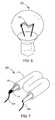
- FIG. 6is an LED light bulb disclosed in the disclosure.
- FIG. 7demonstrates an LED bulb disclosed in the disclosure.
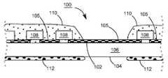
- FIG. 1shows perspective and cross sectional views of the LED assembly 100 .
- the LED assembly 100is flexible, and is capable of being curved to be a tape on a reel. Depending on actual applications, the LED assembly 100 could be cut into pieces with proper lengths, each capable of being a light source in a lighting apparatus such as a light bulb.
- the cross sectional views A, B and Care derived from different locations of the LED assembly 100 in FIG. 1 .
- the LED assembly 100has a flexible, transparent substrate 106 , which is, in one embodiment, composed of a non-conductive material such as glass or resin.
- the transparent substrate 106has surfaces 102 and 104 opposite to each other, and facing the opposite directions respectively and sidewalls 120 and 124 on the surfaces 102 and 104 .
- the transparent substrate 106is a thin, longitudinal strip, having two opposite ends 114 and 116 .
- “transparent”means having the property of transmitting rays of light, and could refer to as transparent, translucent or semitransparent.
- the bodies situated beyond or behind the transparent substrate 106could be distinctly or obscurely seen. Thickness of the transparent substrate 106 , or the distance between the surfaces 102 and 104 , could be 150 micrometer or less.
- FIG. 2is a cross sectional view of the LED assembly 100 along a longitudinal line passing through ends 114 and 116 .
- FIGS. 3A and 3Bshow two opposite surfaces of the LED assembly 100 .
- conductive sections 105On the surface 102 of the flexible, transparent substrate 106 has conductive sections 105 , which are formed by printing for example.
- Another method of forming the conductive sections 105includes forming designed conductive patterns through masks, comprising steps of coating a conductive film on the surface 102 , and patterning the conductive film by lithography and etching to form conductive patterns on the surface 102 , wherein the conductive sections 105 can be further divided into different conductive sections 105 .
- the conductive sections 105could be composed of transparent material, such as indium tin oxide (ITO) or silver thin film, and the thickness of the thin film should be well controlled to be transparent to the light emitted from the blue LED chips 108 .
- ITOindium tin oxide
- FIGS. 1 , 2 , 3 A and 3 Bhas blue LED chips 108 on the surface 102 , each connecting between two adjacent conductive sections 105 .
- a blue LED chip 108might have only one single LED cell, having a forward voltage of about 2 to 3 volts, and this kind of LED chip is referred to as a low-voltage LED chip hereinafter.
- a blue LED chip 108 in another embodimentmight include several LED cells connected in series, and is referred to as a high-voltage LED chip hereinafter, because the forward voltage of the LED chip could be as high as 12V, 24V, or 48V, much higher than that of a low-voltage LED chip.
- each LED cell in an LED chiphas a light-emitting layer, and the LED cell might be formed on an epitaxial or non-epitaxial substrate. More specifically, the LED cells without individual substrate in a high-voltage LED chip are electrically connected to each other on a common substrate by semiconductor processes.
- the LED assembly 100on the surface 102 of the LED assembly 100 are not only blue LED chips 108 but also LED chips (not shown) that emit light different than blue.
- the LED assembly 100could include red, green, and/or yellow LED chips to have light mixture with a desired spectrum or an appropriate color temperature.
- Some or all of the LED chips in the LED assembly 100whether it is blue or not, could be correspondingly replaced by LED packages with one or more LED chips in some embodiments.
- the blue LED chips 108 in FIGS. 1 , 2 and 3 Aare positioned on the surface 102 and arranged as a row along a longitudinal line connecting the ends 114 and 116 .
- the cathode and anode of one blue LED chip 108contact with two adjacent conductive sections 105 respectively, in such a way that all the blue LED chips 108 are electrically connected in series and perform as an LED with a forward voltage higher than that of the individual LED chip 108 , where the forward voltage is the summation of the forward voltages of the individual blue LED chips 108 .
- This disclosureis not limited to, however.
- the blue LED chips 108 and any other kinds of LED chips on the surface 102could be connected in many different configurations, including series, parallel, and the combination thereof.
- solder paste jointsare used to mount the blue LED chips 108 on the conductive sections 105 , with a flip chip technique, to provide both electric interconnection and mechanical adhesion. Even though solder paste is opaque, the joints hardly block or diminish the light emitted from the LED assembly 100 because they are tiny in size and could be ignored in view of the overall light intensity.
- an anisotropic conductive filmis used to mount the blue LED chips 108 on the conductive sections 105 .
- the conductive sections 105are first coated with an ACF, and the blue LED chips 108 are then mounted on the conductive sections 105 through ACF, which provides adhesion and electric connection between the blue LED chips and the conductive sections 105 .
- eutectic alloy or silver pastecould be employed to mount the blue LED chips 108 on the conductive sections 105 .
- each of the blue LED chips 108is mounted on a portion of the surface 102 where no conductive sections 105 are formed, and interconnection means, such as bonding wires, are then formed to connect the blue LED chips 108 to the conductive sections 105 .
- interconnection meanssuch as bonding wires
- material with excellent thermal conductivity but poor electric conductivityis employed first to adhere the blue LED chips 108 to the surface 102 or the LED chips 108 are directly connected to the surface 102 , and then bonding wires are provided to electrically connect blue LED chips 108 and conductive sections 105 .
- the phosphor layer 110comprises epoxy or plastic and wavelength conversion material dispersed therein, such as phosphor or dye powder, that is capable of being stimulated by some light emitted from the blue LED chips (with a dominant wavelength ranging from 430 nm to 480 nm) to produce green or yellow light (with a dominant wavelength ranging from 540 nm to 590 nm), so that the mixture of the lights is perceived as white light by human eyes.
- the phosphor layer 110could comprise thermosetting resin, thermoplastic resin, light-cured resin, acrylic resin, epoxy, or silicone, for example.
- FIGS. 2 and 3Ashow that the blue LED chips 108 are covered by the phosphor layer 110 , which does not cover all conductive sections 105 .
- the cross sectional view C in FIG. 1also demonstrates a portion of a conductive section 105 is not covered by the phosphor layer 110 .
- the phosphor layer 110 shown in FIGS. 2 and 3Acould form segments with different sizes, and the segments are arranged in a row aligned with a longitudinal line connecting ends 114 and 116 . The gap between two adjacent segments exposes a portion of a conductive section 105 .
- Dispensing or screen printingcould form the phosphor layer 110 on the blue LED chips 108 .
- Each segment of the phosphor layer 110could cover one or more blue LED chips 108 . Possibly, one segment of the phosphor layer only covers one blue LED chip 108 , while another segment covers several blue LED chips 108 .
- the phosphor layer 110could be epoxy or silicone, for example, dispersed therein with one kind or several kinds of phosphor, and the phosphor includes, but is not limited to, yttrium aluminum garnet (YAG), terbium aluminum garnet (TAG), Eu-activated alkaline earth silicate, and SiAlON.
- the phosphorcould be green-emitting or yellow-emitting phosphor having elements selected from a group consisting of Sr, Ga, S, P, Si, O, Gd, Ce, Lu, Ba, Ca, N, Eu, Y, Cd, Zn, Se, and Al.
- Thickness and coverage of the phosphor layer 110could determine the flexibility of the LED assembly 100 .
- the phosphor layer 112on the surface 104 , which is opposite to the surface 102 , is another wavelength conversion layer, the phosphor layer 112 , composition and manufacturing of which could be the same or similar with those of the phosphor layer 110 . Similar with the phosphor layer 110 , the phosphor layer 112 is formed to have segments and gaps alternatively arranged in a row. Basically, segments of phosphor layer 112 are formed on the positions of the surface 104 corresponding to the blue LED chips 108 . Moreover, one segment of the phosphor layer 112 is corresponding to one blue LED chip 108 , to multiple blue LED chips 108 , or to a segment of phosphor layer 110 .
- each blue LED chip 108is substantially sandwiched by one segment of the phosphor layer 112 and one segment of the phosphor layer 110 .
- One segment of the phosphor layer 112could be used for, in association with the phosphor layer 110 , sandwiching only one blue LED chip 108 in one embodiment, or several blue LED chips 108 in another embodiment.
- the phosphor layer 112 on the surface 104might be absent in some embodiments while the phosphor layer 110 still presents.
- the phosphor layer 112 and the phosphor layer 110could differ in materials in the phosphor or in the lights emitted by the phosphors having same chemical elements.
- red LED chipsthere on the surface 102 in one embodiment are red LED chips (not shown), and they could be sandwiched between the phosphor layers 110 and 112 .
- covering on the red LED chipsis not the phosphor layer 110 , but a transparent resin or epoxy layer that has no or little phosphor; and there is no phosphor layer 112 on the locations of the surface 104 corresponding to the red LED chips.
- sidewalls 120 and 124connect between surfaces 102 and 104 , and are not covered or partially covered by the phosphor layer 110 or 112 .
- a cutting instrumentsuch as a pair of scissors, a slitter, a film slitter or a cutting machine, could be used to cut the LED assembly 100 at the locations where the conductive sections 105 located without being covered by the phosphor layer 110 to result in several flexible LED filaments.
- An LED filament 130 produced by the cuttingis shown in FIG. 4 , where the LED filament 130 has, at its two ends, two conductive sections 105 uncovered by the phosphor layer 110 to be its cathode and anode respectively, from which the LED chips in the LED filament 130 might be driven by a power supply.
- FIG. 5demonstrates an LED light bulb 200 with the LED filament 130 in FIG. 4 .
- the light bulb 200further includes a bulb base 202 , a transparent or semitransparent lamp cover 204 , supports 206 , conductive wires 207 and an LED filament 130 .
- the bulb base 202could be an Edison screw base capable of screwing into a matching socket and could be equipped with an LED driving circuit 208 therein.
- the lamp cover 204is fixed on the bulb base 202 , and the space enclosed by the lamp cover 204 and the bulb base 202 is referred to as an inner space. Inside the inner space, the LED filament 130 is fixed on the supports 206 , which in one embodiment are substantially transparent in regard to the light emitted from the LED filament 130 .
- the LED filament 130is curved to form a circle with a notch, and the circle is on a plane perpendicular to the screw axis 212 of the bulb base 202 and the lamp cover 204 .
- the screw axis 212passes the center of the circle.
- the conductive wires 207could be used to mechanically support the LED filament 130 .
- the conductive wires 207also electrically connect the two conductive sections 105 at two ends of the LED filament 130 electrically and the LED driving circuit 208 in the bulb base 202 , so that the LED filament 130 can be driven to illuminate.
- Blue light leakagecould be decreased or eliminated.
- the light that the blue LED chips 108 emit in all the directionsconfronts either the phosphor layer 112 or the phosphor layer 110 , except the directions to the sidewall 120 or 124 . It implies that blue light leakage resulted from the blue light emitted from the blue LED chips leaves while the light passing through the sidewalls 120 and 124 .
- Experiment resultsdemonstrate that when the sidewalls 120 and 124 are small enough (or the substrate 106 is thin enough), for example smaller than 150 micrometer in height or in thickness, the blue light leakage through the sidewalls 120 and 124 is hardly detectable and could be ignored.
- Each blue LED chip 108could light in all directions as it is substantially not surrounded or encapsulated by opaque material. That is, the blue LED chip 108 is substantially surrounded or encapsulated by the phosphor layers 112 and 110 , two transparent layers with phosphor dispersed therein.
- the LED assembly 100is easy for storage, as it could be curved into a tape on a reel.
- the length of an LED filamentcan be adjusted. For producing a filament with an expected length, it might only need a knife or a pair of scissors to cut at appropriate locations of the LED assembly 100 .
- the forward voltage of an LED filamentcan be adjusted. Based upon the forward voltage required in an appliance, an assembler could cut the LED assembly 100 to have a filament with a suitable forward voltage. For example, if three blue LED chips 108 are connected in series between every two adjacent exposed conductive sections 105 in FIG. 1 , a filament with an integral multiple of three blue LED chips 108 connected in series can be easily produced by cutting the LED assembly 100 . In case that there is only one blue LED chip 108 between every two adjacent exposed conductive sections 105 , it is possible to form an LED filament having any number of the blue LED chips 108 connected in series.
- the assemblingcould be realized by simple conventional soldering which adjoins the conductive wires 207 and the LED filament.
- Supports 206can be optionally provided to support the filament 130 within the bulb at different locations, and the power supply is connected to the conductive sections 105 at the ends of the filament 130 .
- the filament 130is curved to be almost a circle which is omnidirectional in respect with the screw axis 212 , while the blue LED chips 108 in the filament 130 emit light in all directions. Accordingly, the light bulb 200 could be an omnidirectional lighting apparatus while the lamp cover 204 is not opaque material.
- FIG. 5An LED filament according to the disclosure is flexible and could be curved into any shape suitable for a lighting apparatus.
- Another LED bulb 300 according to the disclosureis demonstrated in FIG. 6 , where the LED filament 130 has an arc, or a curved line shape, and is only supported or fixed in an inner space by two conductive supports.
- FIG. 7demonstrates another LED bulb 400 of the disclosure, which has a transparent or translucent serpentine tube 410 , and the LED filament 130 meanders through its channel. Two exposed conductive sections 105 at the ends of the LED filament 130 in FIG.
- the LED filament 130could be adopted as a lighting source within a channel letter.
- the LED assembly according to embodiments of the disclosureis not limited to have only blue LED chips, and possibly has LED chips with a color other than blue. Furthermore, and not all blue LED chips are covered by a common phosphor layer. In one embodiment of the disclosure, some blue LED chips 108 are covered by the phosphor layer 110 , but some are covered by another phosphor layer with phosphor different from that in the phosphor layer 110 .
Landscapes
- Engineering & Computer Science (AREA)
- Physics & Mathematics (AREA)
- Microelectronics & Electronic Packaging (AREA)
- Optics & Photonics (AREA)
- General Engineering & Computer Science (AREA)
- Led Device Packages (AREA)
- Non-Portable Lighting Devices Or Systems Thereof (AREA)
- Fastening Of Light Sources Or Lamp Holders (AREA)
- Arrangement Of Elements, Cooling, Sealing, Or The Like Of Lighting Devices (AREA)
Abstract
Description
Claims (13)
Priority Applications (1)
| Application Number | Priority Date | Filing Date | Title |
|---|---|---|---|
| US15/863,710USRE49031E1 (en) | 2013-09-11 | 2018-01-05 | Flexible LED assemblies and LED light bulbs |
Applications Claiming Priority (3)
| Application Number | Priority Date | Filing Date | Title |
|---|---|---|---|
| TW102132806ATWI599745B (en) | 2013-09-11 | 2013-09-11 | Flexible LED assembly and LED bulb |
| TW102132806A | 2013-09-11 | ||
| TW102132806 | 2013-09-11 |
Related Child Applications (1)
| Application Number | Title | Priority Date | Filing Date |
|---|---|---|---|
| US15/863,710ReissueUSRE49031E1 (en) | 2013-09-11 | 2018-01-05 | Flexible LED assemblies and LED light bulbs |
Publications (2)
| Publication Number | Publication Date |
|---|---|
| US20150069442A1 US20150069442A1 (en) | 2015-03-12 |
| US9231171B2true US9231171B2 (en) | 2016-01-05 |
Family
ID=52624690
Family Applications (2)
| Application Number | Title | Priority Date | Filing Date |
|---|---|---|---|
| US14/480,084CeasedUS9231171B2 (en) | 2013-09-11 | 2014-09-08 | Flexible LED assemblies and LED light bulbs |
| US15/863,710ActiveUSRE49031E1 (en) | 2013-09-11 | 2018-01-05 | Flexible LED assemblies and LED light bulbs |
Family Applications After (1)
| Application Number | Title | Priority Date | Filing Date |
|---|---|---|---|
| US15/863,710ActiveUSRE49031E1 (en) | 2013-09-11 | 2018-01-05 | Flexible LED assemblies and LED light bulbs |
Country Status (4)
| Country | Link |
|---|---|
| US (2) | US9231171B2 (en) |
| JP (2) | JP6494963B2 (en) |
| CN (2) | CN104425476A (en) |
| TW (1) | TWI599745B (en) |
Cited By (9)
| Publication number | Priority date | Publication date | Assignee | Title |
|---|---|---|---|---|
| US20160363267A1 (en)* | 2015-06-10 | 2016-12-15 | Jiaxing Super Lighting Electric Applicance Co., Ltd. | Led filament, led filament assembly and led bulb |
| US20190157250A1 (en)* | 2017-11-23 | 2019-05-23 | Osram Opto Semiconductors Gmbh | Led filament comprising conversion layer |
| US10598314B2 (en) | 2017-03-31 | 2020-03-24 | Liquidleds Lighting Corp. | LED lamp |
| US11149908B1 (en)* | 2018-08-02 | 2021-10-19 | Osram Oled Gmbh | Light emitting filament device and method of manufacturing a light emitting filament device |
| US20220078892A1 (en)* | 2014-09-28 | 2022-03-10 | Zhejiang Super Lighting Electric Appliance Co.,Ltd | Led filament and led light bulb |
| US11997768B2 (en) | 2014-09-28 | 2024-05-28 | Zhejiang Super Lighting Electric Appliance Co., Ltd | LED filament and LED light bulb |
| US12060455B2 (en) | 2018-04-17 | 2024-08-13 | Jiaxing Super Lighting Electric Appliance Co., Ltd | LED filament and LED light bulb |
| US12066155B2 (en) | 2014-09-28 | 2024-08-20 | Zhejiang Super Lighting Electric Ap | LED bulb lamp |
| US12313227B2 (en) | 2014-09-28 | 2025-05-27 | Zhejiang Super Lighting Electric Appliance Co., Ltd. | LED filament and LED light bulb |
Families Citing this family (77)
| Publication number | Priority date | Publication date | Assignee | Title |
|---|---|---|---|---|
| US10473271B2 (en) | 2015-08-17 | 2019-11-12 | Zhejiang Super Lighting Electric Appliance Co., Ltd. | LED filament module and LED light bulb |
| US10544905B2 (en) | 2014-09-28 | 2020-01-28 | Zhejiang Super Lighting Electric Appliance Co., Ltd. | LED bulb lamp |
| US10240724B2 (en) | 2015-08-17 | 2019-03-26 | Zhejiang Super Lighting Electric Appliance Co., Ltd. | LED filament |
| US10677396B2 (en) | 2006-07-22 | 2020-06-09 | Jiaxing Super Lighting Electric Appliance Co., Ltd | LED light bulb with symmetrical filament |
| US10487987B2 (en) | 2015-08-17 | 2019-11-26 | Zhejiang Super Lighting Electric Appliance Co., Ltd. | LED filament |
| US10655792B2 (en) | 2014-09-28 | 2020-05-19 | Zhejiang Super Lighting Electric Appliance Co., Ltd. | LED bulb lamp |
| US9166116B2 (en) | 2012-05-29 | 2015-10-20 | Formosa Epitaxy Incorporation | Light emitting device |
| US11480305B2 (en) | 2014-09-25 | 2022-10-25 | Jiaxing Super Lighting Electric Appliance Co., Ltd. | LED tube lamp |
| US11015764B2 (en) | 2014-09-28 | 2021-05-25 | Zhejiang Super Lighting Electric Appliance Co., Ltd | LED light bulb with flexible LED filament having perpendicular connecting wires |
| US10784428B2 (en) | 2014-09-28 | 2020-09-22 | Zhejiang Super Lighting Electric Appliance Co., Ltd. | LED filament and LED light bulb |
| US10982816B2 (en) | 2014-09-28 | 2021-04-20 | Zhejiang Super Lighting Electric Appliance Co., Ltd | LED light bulb having uniform light emmision |
| US11543083B2 (en) | 2014-09-28 | 2023-01-03 | Zhejiang Super Lighting Electric Appliance Co., Ltd | LED filament and LED light bulb |
| US10976009B2 (en) | 2014-09-28 | 2021-04-13 | Zhejiang Super Lighting Electric Appliance Co., Ltd | LED filament light bulb |
| US11259372B2 (en) | 2015-06-10 | 2022-02-22 | Zhejiang Super Lighting Electric Appliance Co., Ltd | High-efficiency LED light bulb with LED filament therein |
| US11028970B2 (en) | 2014-09-28 | 2021-06-08 | Zhejiang Super Lighting Electric Appliance Co., Ltd | LED filament light bulb having organosilicon-modified polyimide resin composition filament base layer |
| US10845008B2 (en) | 2014-09-28 | 2020-11-24 | Zhejiang Super Lighting Electric Appliance Co., Ltd. | LED filament and LED light bulb |
| US11421827B2 (en) | 2015-06-19 | 2022-08-23 | Zhejiang Super Lighting Electric Appliance Co., Ltd | LED filament and LED light bulb |
| US20220086975A1 (en)* | 2014-09-28 | 2022-03-17 | Zhejiang Super Lighting Electric Appliance Co., Ltd. | Led filament and led light bulb |
| US11686436B2 (en)* | 2014-09-28 | 2023-06-27 | Zhejiang Super Lighting Electric Appliance Co., Ltd | LED filament and light bulb using LED filament |
| US11085591B2 (en) | 2014-09-28 | 2021-08-10 | Zhejiang Super Lighting Electric Appliance Co., Ltd | LED light bulb with curved filament |
| US11525547B2 (en) | 2014-09-28 | 2022-12-13 | Zhejiang Super Lighting Electric Appliance Co., Ltd | LED light bulb with curved filament |
| US12007077B2 (en) | 2014-09-28 | 2024-06-11 | Zhejiang Super Lighting Electric Appliance Co., Ltd. | LED filament and LED light bulb |
| TWI575184B (en)* | 2015-08-11 | 2017-03-21 | LED bulb structure | |
| US11168844B2 (en) | 2015-08-17 | 2021-11-09 | Zhejiang Super Lighting Electric Appliance Co., Ltd | LED light bulb having filament with segmented light conversion layer |
| GB2543139B (en)* | 2015-08-17 | 2018-05-23 | Jiaxing Super Lighting Electric Appliance Co Ltd | LED light bulb and LED filament thereof |
| US10359152B2 (en) | 2015-08-17 | 2019-07-23 | Zhejiang Super Lighting Electric Appliance Co, Ltd | LED filament and LED light bulb |
| CN106555942A (en)* | 2015-09-29 | 2017-04-05 | 上海德士电器有限公司 | LED light source module and the bubble shape lamp including which |
| USD785821S1 (en) | 2015-12-06 | 2017-05-02 | GE Lighting Solutions, LLC | Retrofit lamp with LED light source filament |
| USD789569S1 (en) | 2015-12-06 | 2017-06-13 | GE Lighting Solutions, LLC | Retrofit lamp with LED light source filament |
| USD790086S1 (en) | 2015-12-06 | 2017-06-20 | GE Lighting Solutions, LLC | Retrofit lamp with LED light source filament |
| USD780958S1 (en) | 2015-12-06 | 2017-03-07 | GE Lighting Solutions, LLC | Retrofit lamp with LED light source filament |
| US9971263B2 (en)* | 2016-01-08 | 2018-05-15 | Canon Kabushiki Kaisha | Toner |
| CN205388272U (en)* | 2016-01-19 | 2016-07-20 | 鹤山建豪电光源有限公司 | LED automobile bulb |
| WO2017133770A1 (en)* | 2016-02-04 | 2017-08-10 | Osram Opto Semiconductors Gmbh | Led-filament and illuminant with led-filament |
| CA3011489A1 (en)* | 2016-04-27 | 2017-11-02 | Jiaxing Super Lighting Electric Appliance Co., Ltd | Led light bulb |
| CN205746257U (en)* | 2016-05-12 | 2016-11-30 | 广州市五度光电科技有限公司 | A kind of LED lamp bar that can arbitrarily bend and shape |
| CN107676637A (en)* | 2016-08-01 | 2018-02-09 | 漳州立达信光电子科技有限公司 | Omnidirectional LED lights |
| US20190191535A1 (en)* | 2016-09-05 | 2019-06-20 | Signify Holding B.V. | Led-filament and lighting device comprising the led-filament |
| EP3290773B1 (en)* | 2016-09-05 | 2019-05-01 | Double Good Co. | Led light bulb and fabrication method thereof |
| TW201705557A (en)* | 2016-10-26 | 2017-02-01 | Liquidleds Lighting Corp | LED filament with heat dissipation structure and LED bulb using the same |
| JP6850112B2 (en)* | 2016-11-28 | 2021-03-31 | 株式会社ディスコ | LED assembly method |
| US10535805B2 (en) | 2017-01-13 | 2020-01-14 | Intematix Corporation | Narrow-band red phosphors for LED lamps |
| US11212967B2 (en) | 2017-01-20 | 2022-01-04 | Hgci, Inc. | Light emitting structures |
| JP3210623U (en)* | 2017-03-10 | 2017-06-01 | スワン電器株式会社 | Hanging decorative lamp |
| CN107514553A (en)* | 2017-07-31 | 2017-12-26 | 浙江亿米光电科技有限公司 | A kind of bulb with self-forming LED light source |
| DE102017121186A1 (en)* | 2017-09-13 | 2019-03-14 | Eaton Intelligent Power Limited | Signal light and signal module |
| EP3480510B1 (en)* | 2017-11-03 | 2020-03-25 | Xiamen Eco Lighting Co., Ltd. | Led lighting apparatus |
| KR102527952B1 (en)* | 2017-11-10 | 2023-05-03 | 서울반도체 주식회사 | Light emitting device filament |
| KR102459144B1 (en) | 2017-11-20 | 2022-10-27 | 서울반도체 주식회사 | Bulb-type lighting source |
| WO2019129034A1 (en) | 2017-12-26 | 2019-07-04 | 嘉兴山蒲照明电器有限公司 | Light-emitting diode filament and light-emitting diode bulb |
| US10790419B2 (en) | 2017-12-26 | 2020-09-29 | Jiaxing Super Lighting Electric Appliance Co., Ltd | LED filament and LED light bulb |
| CN108269901B (en)* | 2018-01-16 | 2019-08-23 | 深圳市晨日科技股份有限公司 | A kind of LED upside-down mounting linear light source and preparation method thereof for fluorescent tube |
| EP3784954B1 (en)* | 2018-04-26 | 2025-01-29 | Lumileds LLC | Flexible led lighting strip with slanted leds |
| US10371325B1 (en) | 2018-06-25 | 2019-08-06 | Intematix Corporation | Full spectrum white light emitting devices |
| US10685941B1 (en)* | 2019-07-09 | 2020-06-16 | Intematix Corporation | Full spectrum white light emitting devices |
| CN110957307A (en)* | 2018-09-27 | 2020-04-03 | Bgt材料有限公司 | LED Filament and LED Filament Bulbs |
| US10752294B2 (en) | 2018-11-28 | 2020-08-25 | Ford Global Technologies, Llc | Vehicle with removable outer body panel and detachable tail lamp support, and corresponding method |
| JP7242894B2 (en) | 2019-03-18 | 2023-03-20 | インテマティックス・コーポレーション | Packaged white light emitting device with photoluminescent layered structure |
| CN119208311A (en) | 2019-03-18 | 2024-12-27 | 英特曼帝克司公司 | LED Filament |
| US11781714B2 (en) | 2019-03-18 | 2023-10-10 | Bridgelux, Inc. | LED-filaments and LED-filament lamps |
| WO2020190960A1 (en)* | 2019-03-18 | 2020-09-24 | Intematix Corporation | Led-filament |
| US11342311B2 (en) | 2019-03-18 | 2022-05-24 | Intematix Corporation | LED-filaments and LED-filament lamps utilizing manganese-activated fluoride red photoluminescence material |
| EP3715699A1 (en)* | 2019-03-29 | 2020-09-30 | GaN Power Technology Co., Ltd. | Led light bulb |
| EP3963252B1 (en) | 2019-05-02 | 2023-11-22 | Signify Holding B.V. | Led filament lamp |
| US11887973B2 (en) | 2019-07-09 | 2024-01-30 | Intematix Corporation | Full spectrum white light emitting devices |
| CN110739382B (en)* | 2019-09-03 | 2020-12-29 | 浙江凯耀照明有限责任公司 | A LED light-emitting device with high color rendering index and light efficiency |
| US11796141B2 (en) | 2019-09-17 | 2023-10-24 | Signify Holding B.V. | Lighting device comprising an LED strip |
| CN118224553A (en)* | 2019-09-19 | 2024-06-21 | 昕诺飞控股有限公司 | LED filament arrangement comprising at least one bending unit |
| KR20230020503A (en)* | 2020-06-03 | 2023-02-10 | 루미레즈 엘엘씨 | Optically embedded flexible filament |
| CN213333738U (en)* | 2020-08-31 | 2021-06-01 | 杭州杭科光电集团股份有限公司 | Color-controllable LED luminescent lamp |
| CN213394756U (en)* | 2020-11-10 | 2021-06-08 | 广东欧曼科技股份有限公司 | Fluorescent LED lamp strip based on CSP or FC chip |
| US12140276B2 (en)* | 2020-12-17 | 2024-11-12 | Signify Holding B.V. | RGB architecture for color controllable LED filament |
| US12429205B2 (en) | 2021-01-05 | 2025-09-30 | Signify Holding B.V. | LED filament arrangement |
| CN117529813A (en)* | 2021-06-22 | 2024-02-06 | 昕诺飞控股有限公司 | LED filament with enhanced phosphor layer for flame appearance |
| CN116123467A (en)* | 2021-11-12 | 2023-05-16 | 液光固态照明股份有限公司 | light emitting diode bulb |
| WO2025008456A1 (en)* | 2023-07-06 | 2025-01-09 | Signify Holding B.V. | Light emitting device |
| WO2025073513A1 (en)* | 2023-10-02 | 2025-04-10 | Signify Holding B.V. | A led filament |
Citations (3)
| Publication number | Priority date | Publication date | Assignee | Title |
|---|---|---|---|---|
| US20090251882A1 (en)* | 2008-04-03 | 2009-10-08 | General Led, Inc. | Light-emitting diode illumination structures |
| US20110163683A1 (en)* | 2011-02-22 | 2011-07-07 | Quarkstar, Llc | Solid State Lamp Using Light Emitting Strips |
| US20130111744A1 (en)* | 2011-09-07 | 2013-05-09 | Michael A. Tischler | Broad-area lighting systems |
Family Cites Families (30)
| Publication number | Priority date | Publication date | Assignee | Title |
|---|---|---|---|---|
| US5660461A (en)* | 1994-12-08 | 1997-08-26 | Quantum Devices, Inc. | Arrays of optoelectronic devices and method of making same |
| JP3075689U (en)* | 2000-08-17 | 2001-02-27 | 舶用電球株式会社 | LED bulb |
| KR100563970B1 (en) | 2004-05-03 | 2006-03-30 | 이엘코리아 주식회사 | Flexible Weapon Elm Dome Sheet and Flexible Weapon Elm Dome Sheet Keypad |
| JP2007165811A (en)* | 2005-12-16 | 2007-06-28 | Nichia Chem Ind Ltd | Light emitting device |
| KR100885894B1 (en)* | 2006-09-29 | 2009-02-26 | 폴리트론 테크놀로지스 인크 | Plain structure of LED light emitting device |
| CN201043697Y (en)* | 2007-04-30 | 2008-04-02 | 陈大庆 | LED picture and text lamp |
| US20110019433A1 (en)* | 2008-03-17 | 2011-01-27 | Osram Gesellschaft Mit Beschraenkter Haftung | Led lighting device |
| JP2010087051A (en) | 2008-09-29 | 2010-04-15 | Toyoda Gosei Co Ltd | Light-emitting device |
| JP5320627B2 (en)* | 2009-05-14 | 2013-10-23 | 東芝ライテック株式会社 | Lamp with lamp and lighting equipment |
| JP4932064B2 (en) | 2010-03-11 | 2012-05-16 | パナソニック株式会社 | Light emitting module, light source device, liquid crystal display device, and method for manufacturing light emitting module |
| JP5533183B2 (en)* | 2010-04-20 | 2014-06-25 | 日亜化学工業株式会社 | LED light source device and manufacturing method thereof |
| JP2012018865A (en)* | 2010-07-09 | 2012-01-26 | Panasonic Corp | Led module and led lamp |
| US9732930B2 (en)* | 2010-07-20 | 2017-08-15 | Panasonic Intellectual Property Management Co., Ltd. | Light bulb shaped lamp |
| BR112013005707B1 (en)* | 2010-09-08 | 2021-03-30 | Zhejiang Ledison Optoelectronics Co., Ltd | LED LAMP |
| CN103069593A (en) | 2010-10-22 | 2013-04-24 | 松下电器产业株式会社 | Mounting board, light emitting device and lamp |
| JP5952828B2 (en)* | 2010-12-22 | 2016-07-13 | コーニンクレッカ フィリップス エヌ ヴェKoninklijke Philips N.V. | LIGHTING DEVICE AND METHOD FOR MANUFACTURING LIGHTING DEVICE |
| US8421111B2 (en)* | 2010-12-27 | 2013-04-16 | Panasonic Corporation | Light-emitting device and lamp |
| US20130141892A1 (en) | 2011-01-14 | 2013-06-06 | Panasonic Corporation | Lamp and lighting apparatus |
| CN102650380A (en)* | 2011-02-25 | 2012-08-29 | 瑞莹光电股份有限公司 | Light emitting diode lamp and manufacturing method thereof |
| CN102650385A (en)* | 2011-02-25 | 2012-08-29 | 瑞莹光电股份有限公司 | Light emitting diode lamp and manufacturing method thereof |
| CN105304800B (en) | 2011-04-20 | 2019-06-11 | 松下电器产业株式会社 | Light emitting device, backlight unit, liquid crystal display device, and lighting device |
| US20130010463A1 (en) | 2011-07-05 | 2013-01-10 | Industrial Technology Research Institute | Illumination device |
| US20120175667A1 (en)* | 2011-10-03 | 2012-07-12 | Golle Aaron J | Led light disposed on a flexible substrate and connected with a printed 3d conductor |
| TW201320412A (en)* | 2011-11-14 | 2013-05-16 | Evergreen Optronics Inc | LED package |
| CN103123949A (en)* | 2011-11-21 | 2013-05-29 | 展晶科技(深圳)有限公司 | Flexible light emitting diode package structure and manufacturing method thereof |
| CN104024723B (en) | 2011-11-23 | 2016-08-24 | 3M创新有限公司 | There is the flexible luminous semiconductor device of three-dimensional structure |
| JP5895166B2 (en)* | 2012-02-13 | 2016-03-30 | パナソニックIpマネジメント株式会社 | Light emitting module, lamp and lighting device |
| TWM459520U (en) | 2013-01-28 | 2013-08-11 | Xu-Wen Liao | LED lamp board structure with double-sided lighting |
| JP6210830B2 (en)* | 2013-05-27 | 2017-10-11 | シチズン時計株式会社 | LED bulb |
| TWI626395B (en) | 2013-06-11 | 2018-06-11 | 晶元光電股份有限公司 | Illuminating device |
- 2013
- 2013-09-11TWTW102132806Apatent/TWI599745B/enactive
- 2014
- 2014-09-08USUS14/480,084patent/US9231171B2/ennot_activeCeased
- 2014-09-10JPJP2014183805Apatent/JP6494963B2/enactiveActive
- 2014-09-11CNCN201410460339.XApatent/CN104425476A/enactivePending
- 2014-09-11CNCN202010418418.XApatent/CN111640736B/enactiveActive
- 2018
- 2018-01-05USUS15/863,710patent/USRE49031E1/enactiveActive
- 2019
- 2019-03-06JPJP2019040727Apatent/JP6851411B2/enactiveActive
Patent Citations (3)
| Publication number | Priority date | Publication date | Assignee | Title |
|---|---|---|---|---|
| US20090251882A1 (en)* | 2008-04-03 | 2009-10-08 | General Led, Inc. | Light-emitting diode illumination structures |
| US20110163683A1 (en)* | 2011-02-22 | 2011-07-07 | Quarkstar, Llc | Solid State Lamp Using Light Emitting Strips |
| US20130111744A1 (en)* | 2011-09-07 | 2013-05-09 | Michael A. Tischler | Broad-area lighting systems |
Cited By (12)
| Publication number | Priority date | Publication date | Assignee | Title |
|---|---|---|---|---|
| US20220078892A1 (en)* | 2014-09-28 | 2022-03-10 | Zhejiang Super Lighting Electric Appliance Co.,Ltd | Led filament and led light bulb |
| US11997768B2 (en) | 2014-09-28 | 2024-05-28 | Zhejiang Super Lighting Electric Appliance Co., Ltd | LED filament and LED light bulb |
| US12066155B2 (en) | 2014-09-28 | 2024-08-20 | Zhejiang Super Lighting Electric Ap | LED bulb lamp |
| US12313227B2 (en) | 2014-09-28 | 2025-05-27 | Zhejiang Super Lighting Electric Appliance Co., Ltd. | LED filament and LED light bulb |
| US20160363267A1 (en)* | 2015-06-10 | 2016-12-15 | Jiaxing Super Lighting Electric Applicance Co., Ltd. | Led filament, led filament assembly and led bulb |
| US9995474B2 (en)* | 2015-06-10 | 2018-06-12 | Jiaxing Super Lighting Electric Appliance Co., Ltd. | LED filament, LED filament assembly and LED bulb |
| US10627098B2 (en)* | 2015-06-10 | 2020-04-21 | Jiaxing Super Lighting Electric Appliance Co., Ltd. | LED filament and LED light bulb having the same |
| US10598314B2 (en) | 2017-03-31 | 2020-03-24 | Liquidleds Lighting Corp. | LED lamp |
| US20190157250A1 (en)* | 2017-11-23 | 2019-05-23 | Osram Opto Semiconductors Gmbh | Led filament comprising conversion layer |
| US10886258B2 (en)* | 2017-11-23 | 2021-01-05 | Osram Oled Gmbh | LED filament comprising conversion layer |
| US12060455B2 (en) | 2018-04-17 | 2024-08-13 | Jiaxing Super Lighting Electric Appliance Co., Ltd | LED filament and LED light bulb |
| US11149908B1 (en)* | 2018-08-02 | 2021-10-19 | Osram Oled Gmbh | Light emitting filament device and method of manufacturing a light emitting filament device |
Also Published As
| Publication number | Publication date |
|---|---|
| CN111640736A (en) | 2020-09-08 |
| TWI599745B (en) | 2017-09-21 |
| JP2015056667A (en) | 2015-03-23 |
| USRE49031E1 (en) | 2022-04-12 |
| CN111640736B (en) | 2022-07-15 |
| JP6494963B2 (en) | 2019-04-03 |
| US20150069442A1 (en) | 2015-03-12 |
| JP2019091944A (en) | 2019-06-13 |
| JP6851411B2 (en) | 2021-03-31 |
| CN104425476A (en) | 2015-03-18 |
| TW201510440A (en) | 2015-03-16 |
Similar Documents
| Publication | Publication Date | Title |
|---|---|---|
| USRE49031E1 (en) | Flexible LED assemblies and LED light bulbs | |
| US11543081B2 (en) | LED assembly with omnidirectional light field | |
| US11450791B2 (en) | LED assembly for omnidirectional light applications | |
| US9157579B2 (en) | LED assembly with omnidirectional light field | |
| US9488345B2 (en) | Light emitting device, illumination apparatus including the same, and mounting substrate | |
| JPWO2014045523A1 (en) | Illumination light source and illumination device | |
| WO2014006901A1 (en) | Lamp and lighting apparatus | |
| CN104976547A (en) | Light emitting diode assembly and light emitting diode bulb using same | |
| US10096747B2 (en) | Lumen maintenance factor deterioration suppressing LED module | |
| US10014458B2 (en) | LED module | |
| US20070075346A1 (en) | Light emitting diode and the package structure thereof | |
| TWI620895B (en) | Flexible led assembly and led light bulb | |
| JP5884054B2 (en) | Illumination light source and illumination device | |
| TWI632322B (en) | Flexible led assembly and led light bulb | |
| TWI655395B (en) | Flexible led assembly and led light bulb | |
| TWI599746B (en) | Flexible led assembly and led light bulb | |
| KR20140123672A (en) | Led lamp | |
| JP2015149240A (en) | Illumination light source and illumination device |
Legal Events
| Date | Code | Title | Description |
|---|---|---|---|
| AS | Assignment | Owner name:HUGA OPTOTECH INC., TAIWAN Free format text:ASSIGNMENT OF ASSIGNORS INTEREST;ASSIGNORS:LIU, HONG-ZHI;CHENG, TZU-CHI;REEL/FRAME:033739/0163 Effective date:20140819 Owner name:INTERLIGHT OPTOTECH CORPORATION, TAIWAN Free format text:ASSIGNMENT OF ASSIGNORS INTEREST;ASSIGNORS:LIU, HONG-ZHI;CHENG, TZU-CHI;REEL/FRAME:033739/0163 Effective date:20140819 | |
| ZAAA | Notice of allowance and fees due | Free format text:ORIGINAL CODE: NOA | |
| ZAAB | Notice of allowance mailed | Free format text:ORIGINAL CODE: MN/=. | |
| STCF | Information on status: patent grant | Free format text:PATENTED CASE | |
| AS | Assignment | Owner name:EPISTAR CORPORATION, TAIWAN Free format text:MERGER;ASSIGNOR:HUGA OPTOTECH INC.;REEL/FRAME:044548/0783 Effective date:20160929 | |
| RF | Reissue application filed | Effective date:20180105 | |
| AS | Assignment | Owner name:KAISTAR LIGHTING (XIAMEN) CO., LTD., CHINA Free format text:ASSIGNMENT OF ASSIGNORS INTEREST;ASSIGNOR:INTERLIGHT OPTOTECH CORPORATION;REEL/FRAME:046577/0672 Effective date:20180403 Owner name:EPISTAR CORPORATION, TAIWAN Free format text:ASSIGNMENT OF ASSIGNORS INTEREST;ASSIGNOR:INTERLIGHT OPTOTECH CORPORATION;REEL/FRAME:046577/0672 Effective date:20180403 | |
| MAFP | Maintenance fee payment | Free format text:PAYMENT OF MAINTENANCE FEE, 4TH YEAR, LARGE ENTITY (ORIGINAL EVENT CODE: M1551); ENTITY STATUS OF PATENT OWNER: LARGE ENTITY Year of fee payment:4 | |
| RF | Reissue application filed | Effective date:20220411 | |
| FEPP | Fee payment procedure | Free format text:MAINTENANCE FEE REMINDER MAILED (ORIGINAL EVENT CODE: REM.); ENTITY STATUS OF PATENT OWNER: LARGE ENTITY | |
| LAPS | Lapse for failure to pay maintenance fees | Free format text:PATENT EXPIRED FOR FAILURE TO PAY MAINTENANCE FEES (ORIGINAL EVENT CODE: EXP.); ENTITY STATUS OF PATENT OWNER: LARGE ENTITY | |
| STCH | Information on status: patent discontinuation | Free format text:PATENT EXPIRED DUE TO NONPAYMENT OF MAINTENANCE FEES UNDER 37 CFR 1.362 | |
| FP | Lapsed due to failure to pay maintenance fee | Effective date:20240105 |