US9227001B2 - High efficiency blood pump - Google Patents
High efficiency blood pumpDownload PDFInfo
- Publication number
- US9227001B2 US9227001B2US12/899,748US89974810AUS9227001B2US 9227001 B2US9227001 B2US 9227001B2US 89974810 AUS89974810 AUS 89974810AUS 9227001 B2US9227001 B2US 9227001B2
- Authority
- US
- United States
- Prior art keywords
- impeller
- pump
- blood pump
- internal surface
- motor
- Prior art date
- Legal status (The legal status is an assumption and is not a legal conclusion. Google has not performed a legal analysis and makes no representation as to the accuracy of the status listed.)
- Active, expires
Links
Images


Classifications
- A61M1/1036—
- A—HUMAN NECESSITIES
- A61—MEDICAL OR VETERINARY SCIENCE; HYGIENE
- A61M—DEVICES FOR INTRODUCING MEDIA INTO, OR ONTO, THE BODY; DEVICES FOR TRANSDUCING BODY MEDIA OR FOR TAKING MEDIA FROM THE BODY; DEVICES FOR PRODUCING OR ENDING SLEEP OR STUPOR
- A61M60/00—Blood pumps; Devices for mechanical circulatory actuation; Balloon pumps for circulatory assistance
- A61M60/40—Details relating to driving
- A61M60/403—Details relating to driving for non-positive displacement blood pumps
- A61M60/419—Details relating to driving for non-positive displacement blood pumps the force acting on the blood contacting member being permanent magnetic, e.g. from a rotating magnetic coupling between driving and driven magnets
- A—HUMAN NECESSITIES
- A61—MEDICAL OR VETERINARY SCIENCE; HYGIENE
- A61M—DEVICES FOR INTRODUCING MEDIA INTO, OR ONTO, THE BODY; DEVICES FOR TRANSDUCING BODY MEDIA OR FOR TAKING MEDIA FROM THE BODY; DEVICES FOR PRODUCING OR ENDING SLEEP OR STUPOR
- A61M60/00—Blood pumps; Devices for mechanical circulatory actuation; Balloon pumps for circulatory assistance
- A61M60/10—Location thereof with respect to the patient's body
- A61M60/122—Implantable pumps or pumping devices, i.e. the blood being pumped inside the patient's body
- A61M60/126—Implantable pumps or pumping devices, i.e. the blood being pumped inside the patient's body implantable via, into, inside, in line, branching on, or around a blood vessel
- A61M60/148—Implantable pumps or pumping devices, i.e. the blood being pumped inside the patient's body implantable via, into, inside, in line, branching on, or around a blood vessel in line with a blood vessel using resection or like techniques, e.g. permanent endovascular heart assist devices
- A61M1/101—
- A61M1/1015—
- A61M1/1017—
- A61M1/122—
- A—HUMAN NECESSITIES
- A61—MEDICAL OR VETERINARY SCIENCE; HYGIENE
- A61M—DEVICES FOR INTRODUCING MEDIA INTO, OR ONTO, THE BODY; DEVICES FOR TRANSDUCING BODY MEDIA OR FOR TAKING MEDIA FROM THE BODY; DEVICES FOR PRODUCING OR ENDING SLEEP OR STUPOR
- A61M60/00—Blood pumps; Devices for mechanical circulatory actuation; Balloon pumps for circulatory assistance
- A61M60/10—Location thereof with respect to the patient's body
- A61M60/122—Implantable pumps or pumping devices, i.e. the blood being pumped inside the patient's body
- A61M60/165—Implantable pumps or pumping devices, i.e. the blood being pumped inside the patient's body implantable in, on, or around the heart
- A61M60/178—Implantable pumps or pumping devices, i.e. the blood being pumped inside the patient's body implantable in, on, or around the heart drawing blood from a ventricle and returning the blood to the arterial system via a cannula external to the ventricle, e.g. left or right ventricular assist devices
- A—HUMAN NECESSITIES
- A61—MEDICAL OR VETERINARY SCIENCE; HYGIENE
- A61M—DEVICES FOR INTRODUCING MEDIA INTO, OR ONTO, THE BODY; DEVICES FOR TRANSDUCING BODY MEDIA OR FOR TAKING MEDIA FROM THE BODY; DEVICES FOR PRODUCING OR ENDING SLEEP OR STUPOR
- A61M60/00—Blood pumps; Devices for mechanical circulatory actuation; Balloon pumps for circulatory assistance
- A61M60/20—Type thereof
- A61M60/205—Non-positive displacement blood pumps
- A61M60/216—Non-positive displacement blood pumps including a rotating member acting on the blood, e.g. impeller
- A61M60/226—Non-positive displacement blood pumps including a rotating member acting on the blood, e.g. impeller the blood flow through the rotating member having mainly radial components
- A61M60/232—Centrifugal pumps
- A—HUMAN NECESSITIES
- A61—MEDICAL OR VETERINARY SCIENCE; HYGIENE
- A61M—DEVICES FOR INTRODUCING MEDIA INTO, OR ONTO, THE BODY; DEVICES FOR TRANSDUCING BODY MEDIA OR FOR TAKING MEDIA FROM THE BODY; DEVICES FOR PRODUCING OR ENDING SLEEP OR STUPOR
- A61M60/00—Blood pumps; Devices for mechanical circulatory actuation; Balloon pumps for circulatory assistance
- A61M60/40—Details relating to driving
- A61M60/403—Details relating to driving for non-positive displacement blood pumps
- A61M60/422—Details relating to driving for non-positive displacement blood pumps the force acting on the blood contacting member being electromagnetic, e.g. using canned motor pumps
- A—HUMAN NECESSITIES
- A61—MEDICAL OR VETERINARY SCIENCE; HYGIENE
- A61M—DEVICES FOR INTRODUCING MEDIA INTO, OR ONTO, THE BODY; DEVICES FOR TRANSDUCING BODY MEDIA OR FOR TAKING MEDIA FROM THE BODY; DEVICES FOR PRODUCING OR ENDING SLEEP OR STUPOR
- A61M60/00—Blood pumps; Devices for mechanical circulatory actuation; Balloon pumps for circulatory assistance
- A61M60/80—Constructional details other than related to driving
- A61M60/802—Constructional details other than related to driving of non-positive displacement blood pumps
- A61M60/804—Impellers
- A61M60/806—Vanes or blades
- A—HUMAN NECESSITIES
- A61—MEDICAL OR VETERINARY SCIENCE; HYGIENE
- A61M—DEVICES FOR INTRODUCING MEDIA INTO, OR ONTO, THE BODY; DEVICES FOR TRANSDUCING BODY MEDIA OR FOR TAKING MEDIA FROM THE BODY; DEVICES FOR PRODUCING OR ENDING SLEEP OR STUPOR
- A61M60/00—Blood pumps; Devices for mechanical circulatory actuation; Balloon pumps for circulatory assistance
- A61M60/80—Constructional details other than related to driving
- A61M60/802—Constructional details other than related to driving of non-positive displacement blood pumps
- A61M60/818—Bearings
- A61M60/824—Hydrodynamic or fluid film bearings
- A—HUMAN NECESSITIES
- A61—MEDICAL OR VETERINARY SCIENCE; HYGIENE
- A61M—DEVICES FOR INTRODUCING MEDIA INTO, OR ONTO, THE BODY; DEVICES FOR TRANSDUCING BODY MEDIA OR FOR TAKING MEDIA FROM THE BODY; DEVICES FOR PRODUCING OR ENDING SLEEP OR STUPOR
- A61M2205/00—General characteristics of the apparatus
- A61M2205/82—Internal energy supply devices
- A61M2205/8206—Internal energy supply devices battery-operated
- A—HUMAN NECESSITIES
- A61—MEDICAL OR VETERINARY SCIENCE; HYGIENE
- A61M—DEVICES FOR INTRODUCING MEDIA INTO, OR ONTO, THE BODY; DEVICES FOR TRANSDUCING BODY MEDIA OR FOR TAKING MEDIA FROM THE BODY; DEVICES FOR PRODUCING OR ENDING SLEEP OR STUPOR
- A61M2207/00—Methods of manufacture, assembly or production
- A—HUMAN NECESSITIES
- A61—MEDICAL OR VETERINARY SCIENCE; HYGIENE
- A61M—DEVICES FOR INTRODUCING MEDIA INTO, OR ONTO, THE BODY; DEVICES FOR TRANSDUCING BODY MEDIA OR FOR TAKING MEDIA FROM THE BODY; DEVICES FOR PRODUCING OR ENDING SLEEP OR STUPOR
- A61M60/00—Blood pumps; Devices for mechanical circulatory actuation; Balloon pumps for circulatory assistance
- A61M60/20—Type thereof
- A61M60/205—Non-positive displacement blood pumps
- A—HUMAN NECESSITIES
- A61—MEDICAL OR VETERINARY SCIENCE; HYGIENE
- A61M—DEVICES FOR INTRODUCING MEDIA INTO, OR ONTO, THE BODY; DEVICES FOR TRANSDUCING BODY MEDIA OR FOR TAKING MEDIA FROM THE BODY; DEVICES FOR PRODUCING OR ENDING SLEEP OR STUPOR
- A61M60/00—Blood pumps; Devices for mechanical circulatory actuation; Balloon pumps for circulatory assistance
- A61M60/80—Constructional details other than related to driving
- A61M60/802—Constructional details other than related to driving of non-positive displacement blood pumps
- A61M60/818—Bearings
- A61M60/82—Magnetic bearings
Definitions
- This inventionrelates to implantable rotary blood pumps.
- Non-pulsatile or continuous flow pumpsare typically rotary and propel fluid with impellers that span the spectrum from radial flow centrifugal type impellers to axial flow auger type impellers.
- a common issue encountered by blood pumpsis blood damage.
- the causes of blood damageare mostly attributed to shear stress and heat generated by the bearings supporting the impeller and/or shaft seals of externally driven impellers. Shear stress and/or heat may cause hemolysis, thrombosis, and the like.
- passive permanent magnetic and active controlled magnetic bearingscan be utilized to provide impeller support in blood pumps.
- Magnetic bearingsmay be combined with hydrodynamic bearings to provide total impeller support in blood pumps.
- Some blood pumpsprovide blood flow utilizing a motor that has a shaft mechanically connected to an impeller. Shaft seals may be utilized to separate the motor chamber from the pump chamber. However, shaft seals can fail and generate excess heat allowing blood to enter the motor and/or produce blood clots.
- Some blood pumpsincorporate electric motors into the pumping chamber, rather than providing separate motor and pumping chambers. For example, a stator may be provided in the pump housing and magnets can be incorporated into an impeller to provide a pump impeller that also functions as the rotor of the electric motor.
- Heart pumps that are suitable for adultsmay call for approximately 5 liters/min of blood flow at 100 mm of Hg pressure, which equates to about 1 watt of hydraulic power.
- Some implantable continuous flow blood pumpsconsume significantly more electric power to produce the desired amount of flow and pressure.
- High power consumptionmakes it impractical to implant a power source in the body. For example, size restrictions of implantable power sources may only allow the implantable power source to provide a few hours of operation. Instead, high power consumption blood pumps may provide a wire connected to the pump that exits the body (i.e. percutaneous) for connection to a power supply that is significantly larger than an implantable power source. These blood pumps may require external power to be provided at all times to operate. In order to provide some mobility, external bulky batteries may be utilized. However, percutaneous wires and external batteries can still restrict the mobility of a person with such a blood pump implant.
- such high power consumption blood pumpshave batteries that frequently require recharging thereby limiting the amount of time the person can be away from a charger or power source, batteries that can be heavy or burdensome thereby restricting mobility, percutaneous wires that are not suitable for prolonged exposure to water submersion (i.e. swimming, bathing, etc.), and/or other additional drawbacks.
- blood pumps discussed hereinmay be suitable for use as a ventricular assist device (VAD) or the like because they cause minimal blood damage, are energy efficient, and can be powered by implanted batteries for extended periods of time. Further, these pumps are also beneficial because they may improve the quality of life of a patient with a VAD by reducing restrictions on the patient's lifestyle.
- VADventricular assist device
- An embodiment of a blood pumpincludes a pump housing, wherein the pump housing provides an inlet and outlet.
- the blood pumpalso includes an impeller housed in the pump housing, wherein the impeller is radially supported by a first hydrodynamic bearing that provides at least one row of flow inducing pattern grooves.
- a blood pumpincludes a pump housing, wherein the pump housing provides an inlet and outlet.
- the blood pumpalso includes an impeller housed in the pump housing, wherein the impeller is axially supported by a first hydrodynamic bearing that provides at least one row of flow inducing pattern grooves.
- a pumpincludes a pump housing providing an inlet and outlet and a motor housing, wherein the motor housing houses a motor.
- the pumpalso includes an impeller housed in the pump housing that is radially supported by a hydrodynamic bearing that provides at least one row of pattern grooves.
- the pumpalso provides a magnetic coupling between the motor and the impeller, wherein the magnetic coupling causes the impeller to rotate when the motor rotates.
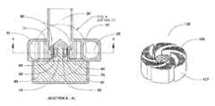
- FIG. 1is a top view of an illustrative embodiment of a pump
- FIG. 2is a cross-sectional side view of an illustrative embodiment of a pump
- FIG. 3is a cross-sectional top view of an illustrative embodiment of a pump
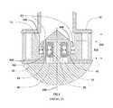
- FIG. 4is a close up cross-sectional view of an area of an illustrative embodiment of a pump
- FIG. 5is a cross-sectional view of an illustrative embodiment of an impeller
- FIG. 6is a cross-sectional view of an illustrative embodiment of a pump housing
- FIG. 7is a cross-sectional view of an illustrative embodiment of a motor housing of a pump
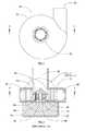
- FIG. 8is an isometric view of an illustrative embodiment of an impeller
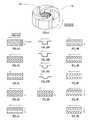
- FIG. 9A-9Kare illustrative embodiments of various types of pattern grooves
- FIG. 10A-10Dare cross-sectional views of various shapes of pattern grooves
- FIG. 11is a cross-sectional side view of an illustrative embodiment of a pump with an axial hydrodynamic bearing
- FIGS. 12A and 12Bare top views of illustrative embodiments of impellers with spiral herringbone grooves and spiral grooves;
- FIG. 13is a close up cross-sectional view of an area of an illustrative embodiment of a pump with an axial hydrodynamic bearing
- FIGS. 14A and 14Bare isometric views of illustrative embodiment of impellers with spiral herringbone grooves and spiral grooves;
- FIG. 15is a cross-sectional side view of an illustrative embodiment of a pump with a conically shaped impeller
- FIG. 16A-16Eare isometric views of illustrative embodiments of conically shaped impellers
- FIG. 17is a close up cross-sectional view of an area of an embodiment of a pump with a conically shaped impeller
- FIG. 18is a cross-sectional side view of an illustrative embodiment of a pump with passive magnetic axial bearings
- FIG. 19is a cross-sectional top view of an illustrative embodiment of a pump with passive magnetic axial bearings.
- FIG. 20is a close up cross-sectional view of an area of an illustrative embodiment of a pump with passive magnetic axial bearings.
- FIG. 21shows a cross-sectional top view of an illustrative embodiment of a pump with an impeller internal surface having a multi-lobe shape.
- FIG. 22shows a close up cross-sectional top view of an illustrative embodiment of a pump with an impeller internal surface having a multi-lobe shape.
- the blood pumpis capable of operating for extended periods of time on a single charge.
- the energy efficient blood pumpmay be suitable for use with an implanted rechargeable power source or the like.
- the pumpcan be installed pericardially (i.e. near the heart) with less complex surgical procedures.
- FIG. 1is a top view of an illustrative embodiment of pump 10 .
- Pump 10is formed from pump housing 15 providing inlet 20 and outlet 25 and motor housing 35 .
- Pump housing 15is composed of two or more pieces and may be joined by welding. However, in other embodiments, pump housing 15 may be joined by fusing, press fit, threading, screw and elastomeric sealing, bonding, fasteners, and/or any other suitable joining method or combinations of joining methods.
- Motor housing 35may be joined to pump housing 15 by welding, fusing, press fit, threading, screw and elastomeric sealing, bonding, fasteners, and/or any other suitable joining method or combinations of joining methods.
- Line A-A passing through pump housing 15indicates the plane from which the cross-sectional view in FIG. 2 is provided.
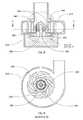
- FIG. 2is a cross-sectional side view of an illustrative embodiment of pump 10 .
- Pump housing 15provides impeller chamber 30 for impeller 75 .
- Impeller chamber 30has inlet 20 for connection to a fluid source and outlet 25 for providing fluid to a desired location.
- Impeller chamber 30is sealed and pressure tight to prevent fluid from entering/exiting impeller chamber 30 from locations other than inlet 20 and outlet 25 .
- Motor housing 35is attached to pump housing 15 to form a fluid and/or pressure tight chamber for motor 40 . While motor housing 35 is shown as a separate component from pump housing 15 , in other embodiments, pump housing 15 and motor housing 35 may be combined to form a single combined housing.
- a cross-sectional view of an illustrative embodiment of motor 40 and motor housing 35 of pump 10is shown in FIG. 7 . In particular, motor housing 35 is shown separate from pump 10 .
- Motor 40is entirely contained between pump housing 15 and motor housing 35 .
- a high efficiency electric motorcan be utilized, such as an electric motor with efficiency of about 85% or greater. However, in other embodiments, any other suitable driving means can be utilized.
- Motor 40provides shaft 45 with hub 50 mounted to shaft 45 .
- Hub 50contains one or more permanent magnets and/or magnetic materials 55 .
- Motor 40rotates shaft 50 causing permanent magnets 55 placed in hub 50 to rotate.
- a motor with a useful life of greater than 10 yearsis utilized.
- the motormay utilize hydrodynamic bearings with fluid support provided by a fluid other than blood.
- Pump housing 15may provide a non-ferromagnetic and/or non-electrically conductive diaphragm 60 separating impeller chamber 30 from the chamber housing motor 40 .
- Diaphragm 60defines cavity 70 providing a region for hub 50 to rotate within.
- diaphragm 60may provide cylindrical bearing surface 65 for impeller 75 to rotate around with hydrodynamic radial support.
- Impeller 75includes one or more permanent magnets and/or magnetic materials 80 . Permanent magnets 80 allow impeller 75 to be magnetically coupled to hub 50 . This magnetic coupling allows motor 40 to cause impeller 75 to rotate when motor 40 rotates hub 50 .
- FIG. 3is a cross-sectional top view of an illustrative embodiment of pump 10 .
- Impeller 75is composed of an array of arc shaped segments 90 joined by central ring 95 .
- Pump housing 15has volute 110 feeding the outlet 25 . In other embodiments, volute 110 could be omitted from pump housing 15 and outlet 25 could have any suitable orientation and shape.
- Pump housing 15is designed in a manner where impeller 75 , when rotated, pressures and moves fluid received from inlet 20 to outlet 25 .
- Permanent magnets 55 in hub 50 and permanent magnets 80 in central ring 95 of impeller 75form a magnetic coupling between the impeller 75 and hub 50 .
- permanent magnets 55 and 80are arranged so that they are attracted to each other.
- permanent magnets 55 and 80provide a minimal magnetic coupling or just enough of a magnetic coupling to rotate impeller 75 under load.
- the attractive force of the magnetic coupling of permanent magnets 55 and 80also provides axial restraint of impeller 75 .
- axial movement of impeller 75would misalign permanent magnets 55 and 80 .
- the magnetic forces of permanent magnets 55 and 80would restrain and re-align the magnets. Because of the magnetic forces caused by permanent magnets 55 and 80 , axial movement of impeller 75 may cause axial force to be exerted on shaft 45 and hub 50 of motor 40 , which is then transferred to bearing(s) (not shown) of motor 40 .
- Permanent magnets 80may be sufficiently small in size that they have no impact on the main fluid flow paths of impeller 75 , thereby allowing the design of impeller 75 to focus on fully optimizing pump efficiency. These benefits can allow pumping efficiencies of greater than 50% to be achieved.
- Impeller internal surface 100 of central ring 95is utilized to form a hydrodynamic bearing between cylindrical bearing surface 65 and impeller internal surface 100 .
- Impeller 75is configured to rotate within impeller chamber 30 with full radial hydrodynamic support from the hydrodynamic bearing formed by cylindrical bearing surface 65 and impeller internal surface 100 .
- a cross section view of an illustrative embodiment of impeller 75is shown in FIG. 5 and an isometric view of an illustrative embodiment of impeller 75 is shown in FIG. 8 , which more thoroughly illustrate the hydrodynamic bearing.
- Pattern grooves on impeller internal surface 100 of impeller 75create a high pressure zone when impeller 75 is rotated, thereby creating a hydrodynamic bearing.
- symmetrical herringbone groovescreate a high pressure zone where the two straight lines of the V-shape grooves meet or the central portion of the symmetrical herringbone grooves.
- the pressure created by the pattern grooves on impeller internal surface 100acts as a radial stabilizing force for impeller 75 when it is rotating concentrically. While the embodiment shown provides symmetrical herringbone grooves on internal surface 100 of impeller 75 , a variety of different groove patterns may be utilized on impeller internal surface 100 to provide a hydrodynamic bearing, which is discussed in detail below. Because low loads are exerted on impeller 75 , the radial hydrodynamic bearing formed between cylindrical bearing surface 65 and impeller internal surface 100 can provide stable radial support of impeller 75 .
- Impeller 75may be an open, pressure balanced type impeller to minimize axial thrust. Impeller 75 is considered to be open because there is no endplate on either side of arc shaped segments 90 . Further, impeller 75 is considered to be pressure balanced because it is designed to minimize axial thrust during the rotation of impeller 75 . However, other types of impellers may be suitable in other embodiments. Impeller 75 could be any other suitable blade shape, rotate in the opposite direction, or non-pressure balanced. For example, other suitable impellers may be semi-open type (i.e. end plate on one side of impeller) or closed type (i.e. end plate on both sides of impeller).
- FIG. 4is a close up cross-sectional view of an area C (see FIG. 2 ) of an illustrative embodiment of pump 10 .
- the magnetic couplingtransmits torque from shaft 45 of the motor 40 to impeller 75 .
- permanent magnets 55 and 80are radially distributed around hub 50 and impeller 75 .
- the poles of permanent magnets 55 and 80are arranged to attract to each other.
- the attractive force of the magnetic coupling of permanent magnets 55 and 80provides axial restraint of impeller 75 .
- permanent magnets 55 and 80are shown as arc shaped like quadrants of a cylinder, it should be recognized that permanent magnets 55 and 80 may be shaped in a variety of different manners to provide the magnetic coupling.
- one or more ring shaped magnets polarized with arc shaped magnetic regions, square/rectangular shaped, rod shaped, disc shaped, or the likemay be utilized.
- permanent magnets 80are shown in the internal portion of impeller 75 .
- Internal magnetic couplingssimilar to the arrangement shown, can be more efficient than face or external type magnetic couplings that place the magnets in the blades of an impeller or rotor because they have a smaller diameter and less eddy current losses.
- Diaphragm 60intermediate the coupling, is non-ferromagnetic and/or non-electrically conductive to minimize eddy current losses.
- couplings with non-electrically conducting diaphragmssuch as bio-compatible ceramic, glass or the like, would exhibit less eddy current losses than those with electrically conducting diaphragms.
- motor 40is of the brushless DC, sensorless, iron core type electric motor with fluid dynamic bearings.
- any suitable type of motorincluding one or more features such as, but not limited to, brushed, hall-effect sensored, coreless, and Halbach array or any type of bearing such as ball or bushing may be used.
- Motor housing 35may include motor control circuitry or be configured to operate with remotely located control circuits.
- Separating motor 40 from impeller chamber 30may allow a high efficiency motor to be utilized. For example, incorporating components into a pump impeller to form the rotor of an electric motor may compromise the design of the pump impeller resulting in reduced efficiency. Further, designing a rotor and stator that is incorporated into the design of a pump may result in an electric motor with large gaps between components of the rotor and stator, thereby decreasing the efficiency of the motor.
- the magnetic coupling arrangements utilized in the embodiments discussed hereinallow a highly efficient motor design to be utilized without compromising the design of an efficient pump impeller.
- a maximum height 320 of the plurality of blades 90overlaps with the internal surface 100 , having a height 312 , the maximum height 320 being in a direction of an axis 350 of impeller rotation.
- a topmost extent 330 of the plurality of blades 90is axially closer to the inlet 20 than is (a) a topmost extent 340 of the hydrodynamic bearing and (b) a bottom 332 of the plurality of blades 90 .
- a maximum cross-sectional dimension 304 of a shape 302 inscribed by all radially innermost edges 300 of the plurality of blades 90is greater than a maximum cross-sectional dimension 310 of the impeller internal surface 100 .
- FIGS. 9A-9K and 10 A- 10 Dillustrate various embodiments of pattern grooves that may be implemented on impeller internal surface 100 .
- impeller internal surface 100provides a hydrodynamic journal bearing.
- impeller internal surface 100may utilize patterned grooves.
- the pattern groovesmay be of any type including, but not limited to, half herringbone ( FIG. 9A ), dual half herringbone ( FIG. 9B ), symmetrical herringbone ( FIG. 9C ), dual symmetrical herringbone ( FIG. 9D ), open symmetrical herringbone ( FIG. 9E ), open dual symmetrical herringbone ( FIG. 9F ), asymmetrical herringbone ( FIG. 9G ), continuous asymmetrical dual herringbone ( FIG.
- Flow inducing pattern groovessuch as half herringbone patterns and asymmetrical herringbone patterns, have the added benefit of producing a substantial secondary flow, particularly along the axis of impeller rotation between cylindrical bearing surface 65 and impeller 75 , thereby minimizing stagnant flow between cylindrical bearing surface 65 and impeller 75 . Because stagnant areas may cause blood clots to form in blood pumps, the secondary flow reduces the chances of blood clots forming.
- each of the pattern grooves of internal surface 100can be shaped in a variety of different manners, such as, but not limited to, rectangular grooves, rectangular grooves with a bevel, semi-circular grooves, elliptical grooves, or the like.
- impeller internal surface 100may also be a plain journal bearing without pattern grooves or a multi-lobe shape, as shown in FIGS. 21 and 22 , that creates a hydrodynamic bearing.
- the pattern grooves or multi-lobe shapesmay be located on the surface of cylindrical bearing surface 65 facing impeller 75 rather than impeller internal surface 100 or the pattern grooves may be located on an outer radial surface of impeller 75 or internal radial surface of pump housing 15 facing the impeller 75 .
- FIG. 11provides a cross-sectional side view of an illustrative embodiment of housing 150 for pump 120 .
- pump 120provides pump housing 150 , impeller 125 , shaft 130 , hub 132 , permanent magnets 135 and 140 , motor housing 142 , motor 145 , and impeller chamber 160 , which all provide a similar function to the components discussed previously.
- These common elementsmay operate in substantially the same manner as previously described. The substantial differences in the embodiments are discussed below.
- FIG. 2provided radial support of impeller 75 utilizing a hydrodynamic bearing.
- one or more external planar surfaces or top surfaces 165 of impeller 125include pattern grooves providing partial axial hydrodynamic support.
- FIG. 13is a close up cross-sectional view of an area D of an illustrative embodiment of pump 120 .
- Each arc shaped segment 127 of impeller 125includes one or more pattern grooves on top surfaces 165 .
- the pattern grooves on top surface 165 of impeller 125 and internal surface 155 of housing 150form a hydrodynamic bearing providing partial axial hydrodynamic support that prevents or minimizes contact between impeller 125 and housing 150 .
- the pattern grooves on top surface 165are considered to be interrupted because they are separated by the flow channels of impeller 125 .
- Pattern grooves on top surface of impeller 125may be any suitable type of grooves including, but not limited to, spiral herringbone and spiral grooves shown in FIGS. 12A and 12B .
- FIGS. 14A and 14Brespectively provide an isometric view of impeller 125 with spiral herringbone and spiral grooves.
- the arrangement of the pattern grooves on top surfaces 165is balanced so that instability during rotation of impeller 125 is prevented or minimized.
- all of the top surfaces 165have pattern grooves in the embodiment shown.
- a balanced arrangement of top surfaces 165 that have pattern grooves and do not have pattern groovesmay be utilized.
- a balanced arrangement of top surfaces 165prevents or minimizes the instability of impeller 125 .
- Examples of balanced arrangements for the embodiment shownmay include, but are not limited to, all top surfaces 165 with grooves or three alternating top surfaces 165 with grooves and three without grooves.
- Flow inducing pattern groovessuch as spiral and spiral herringbone grooves, have the added benefit of producing a substantial secondary flow, particularly between top surface 165 of impeller 75 and internal surface 155 of housing 150 .
- various pattern groove typesincluding symmetrical, asymmetrical, open, and/or dual groove patterns and various groove shapes including rectangular, rectangular with a bevel, semi-circular, and elliptical shown in FIGS. 9A-9K and 10 A- 10 D may be utilized.
- An additional benefit of the hydrodynamic bearing on top surface 165 of impeller 125is that it increases impeller stability during rotation by restraining angular motion along axes normal to the axis of impeller rotation.
- FIG. 15is a cross-sectional side view of an illustrative embodiment of pump 170 with a conically shaped impeller 175 .
- Many of the components of pump 170are substantially similar to the components of the previously discussed illustrative embodiments. These similar components may operate in substantially the same manner as previously described.
- impeller 175is magnetically coupled to shaft 180 of motor 182 . Permanent magnets 185 and 190 couple motor 182 to impeller 175 .
- impeller 175is formed in a generally conical shape.
- Top surfaces 195 of impeller 175 facing internal surface 200 of the pump housing 202are shaped in a manner that provides a hydrodynamic bearing between impeller top surfaces 195 and internal surface 200 .
- FIG. 17is a close up cross-sectional view of an area E of an illustrative embodiment of pump 170 .
- internal surface 205 of impeller 175may include pattern grooves for a hydrodynamic bearing providing radial support.
- Top surfaces 195 of impeller 175are angled to provide a generally conical shaped impeller 175 .
- FIGS. 16A-16Eare views of various embodiments of impeller 175 .
- Impeller 175has multiple blade segments 210 that each have a top surface 195 .
- Top surfaces 195 of blade segments 210may be linear ( FIG. 16A ), convex ( FIG. 16B ), or concave ( FIG. 16C ) surfaces.
- FIGS. 16D-16Eare views of impeller 175 with convex and concave top surfaces 195 .
- top surfaces 195 of impeller 175may incorporate interrupted pattern grooves of any type including, but not limited to, spiral or spiral herringbone grooves.
- the interrupted pattern groovesmay be similar to the pattern grooves shown in FIGS. 12A and 12B .
- the arrangement of the pattern grooves on top surfaces 195is balanced so that instability during rotation of impeller 175 is prevented or minimized.
- all of the top surfaces 195have pattern grooves in the embodiment shown.
- a balanced arrangement of top surfaces 195 that have pattern grooves and do not have pattern groovesmay be utilized.
- Flow inducing pattern groovessuch as spiral and spiral herringbone grooves, have the added benefit of producing a substantial secondary flow, particularly between top surface 195 of impeller 175 and internal surface 200 of pump housing 202 .
- various pattern groove typesincluding symmetrical, asymmetrical, open, and/or dual groove patterns and various groove shapes including rectangular, rectangular with a bevel, semi-circular, and elliptical may alternatively be utilized as shown in FIGS. 9A-9K and 10 A- 10 D.
- top surfaces 195 of impeller 175do not utilize pattern grooves.
- the conical shaped impeller 175may be a pressure balanced type impeller where the magnetic coupling formed by magnets 185 and 190 provides sole axial restraint of impeller 175 .
- top surfaces 195 of impeller 175In addition to the axial restraint provided by the magnetic coupling discussed previously, the hydrodynamic bearing provided by top surfaces 195 of impeller 175 partially restrains axial movement in the direction along the axis of rotation. Because top surfaces 195 are angled, the hydrodynamic bearing of top surfaces 195 also partially restrains radial motion of impeller 175 . Thus, the hydrodynamic bearing of top surfaces 195 provides partial radial and axial support for impeller 175 .
- the hydrodynamic bearings of top surface 195 and impeller internal surface 205 and the partial restraint provided by the magnetic couplingincrease impeller stability during rotation by restraining axial and radial motion.
- FIG. 18is a cross-sectional side view of an illustrative embodiment of pump housing 215 for pump 212 .
- Many of the components of pump 212are substantially similar to the components of the previously discussed illustrative embodiments. These similar components may operate in substantially the same manner as previously described.
- impeller 220is magnetically coupled to shaft 225 .
- Permanent magnets 230 and 235couple the motor to impeller 220 .
- Impeller 220contains permanent magnets 240 and pump housing 215 contains permanent magnets 245 , 250 thereby forming a magnetic thrust bearing for minimizing axial movement of impeller 220 .
- Permanent magnets 245 , 250 in housing 215may be one or more magnets formed into a ring.
- FIG. 20is a close up cross-sectional view of an area H of an illustrative embodiment of pump 212 . Permanent magnets 240 in impeller 220 and permanent magnets 245 in the top portion of pump housing 215 are arranged to provide a repulsive force between impeller 220 and pump housing 215 .
- Permanent magnets 240 in impeller 220 and permanent magnets 250 in the bottom portion of pump housing 215are also arranged to provide a repulsive force between impeller 220 and pump housing 215 .
- the axial restraint forces generated by magnets 240 , 245 , 250are significantly greater than the attractive forces generated by the permanent magnets 230 and 235 and thereby provide sole axial support with greater stiffness for impeller 220 during rotation.
- Magnets 240 in impeller 220 and magnets 245 , 250 in pump housing 215provide large axial restraint forces to allow for increased clearances between impeller 220 and pump housing 215 during rotation. The increased clearances reduce damage to blood and allow for increased flow through the clearances during impeller rotation.
- FIG. 19is a cross sectional top view of an illustrative embodiment of pump 212 .
- Magnets 240are arranged radially around impeller 220 .
- Each blade segment 255 of impeller 220may provide an opening/region for receiving one or more magnets 240 .
- the top and/or bottom surfaces of impeller 220may incorporate various pattern groove types including spiral, spiral herringbone, symmetrical, asymmetrical, open, and/or dual groove patterns. Further, various groove shapes including rectangular, rectangular with a bevel, semi-circular, and elliptical may also be utilized as shown in FIGS. 9A-9K and 10 A- 10 D.
Landscapes
- Health & Medical Sciences (AREA)
- Heart & Thoracic Surgery (AREA)
- Engineering & Computer Science (AREA)
- Cardiology (AREA)
- Life Sciences & Earth Sciences (AREA)
- Public Health (AREA)
- Biomedical Technology (AREA)
- Hematology (AREA)
- Mechanical Engineering (AREA)
- Animal Behavior & Ethology (AREA)
- General Health & Medical Sciences (AREA)
- Anesthesiology (AREA)
- Veterinary Medicine (AREA)
- Vascular Medicine (AREA)
- Physics & Mathematics (AREA)
- Fluid Mechanics (AREA)
- Structures Of Non-Positive Displacement Pumps (AREA)
- External Artificial Organs (AREA)
Abstract
Description
Claims (15)
Priority Applications (18)
| Application Number | Priority Date | Filing Date | Title |
|---|---|---|---|
| US12/899,748US9227001B2 (en) | 2010-10-07 | 2010-10-07 | High efficiency blood pump |
| US13/038,875US8551163B2 (en) | 2010-10-07 | 2011-03-02 | Cardiac support systems and methods for chronic use |
| EP11831215.6AEP2624878A4 (en) | 2010-10-07 | 2011-09-23 | High efficiency blood pump |
| PCT/US2011/052957WO2012047550A1 (en) | 2010-10-07 | 2011-09-23 | Cardiac support systems and methods for chronic use |
| AU2011312596AAU2011312596C1 (en) | 2010-10-07 | 2011-09-23 | High efficiency blood pump |
| EP11831222.2AEP2624879B1 (en) | 2010-10-07 | 2011-09-23 | Cardiac support systems and methods for chronic use |
| EP17169132.2AEP3219339B1 (en) | 2010-10-07 | 2011-09-23 | High efficiency blood pump |
| PCT/US2011/052878WO2012047540A1 (en) | 2010-10-07 | 2011-09-23 | High efficiency blood pump |
| EP14152480.1AEP2727613A3 (en) | 2010-10-07 | 2011-09-23 | High efficiency blood pump |
| AU2011312606AAU2011312606A1 (en) | 2010-10-07 | 2011-09-23 | Cardiac support systems and methods for chronic use |
| US14/018,374US10449277B2 (en) | 2010-10-07 | 2013-09-04 | Cardiac support systems and methods for chronic use |
| US14/158,723US20140200664A1 (en) | 2010-10-07 | 2014-01-17 | High efficiency blood pump |
| US14/973,593US9415147B2 (en) | 2010-10-07 | 2015-12-17 | High efficiency blood pump |
| AU2016203105AAU2016203105B2 (en) | 2010-10-07 | 2016-05-12 | Cardiac support systems and methods for chronic use |
| AU2016204878AAU2016204878B2 (en) | 2010-10-07 | 2016-07-13 | High efficiency blood pump |
| US15/237,508US10568998B2 (en) | 2010-10-07 | 2016-08-15 | High efficiency blood pump |
| US16/659,569US11065437B2 (en) | 2010-10-07 | 2019-10-22 | Cardiac support systems and methods for chronic use |
| US16/800,273US11471662B2 (en) | 2010-10-07 | 2020-02-25 | High efficiency blood pump |
Applications Claiming Priority (1)
| Application Number | Priority Date | Filing Date | Title |
|---|---|---|---|
| US12/899,748US9227001B2 (en) | 2010-10-07 | 2010-10-07 | High efficiency blood pump |
Related Child Applications (4)
| Application Number | Title | Priority Date | Filing Date |
|---|---|---|---|
| US13/038,875Continuation-In-PartUS8551163B2 (en) | 2010-10-07 | 2011-03-02 | Cardiac support systems and methods for chronic use |
| US13/038,875ContinuationUS8551163B2 (en) | 2010-10-07 | 2011-03-02 | Cardiac support systems and methods for chronic use |
| US14/158,723ContinuationUS20140200664A1 (en) | 2010-10-07 | 2014-01-17 | High efficiency blood pump |
| US14/973,593ContinuationUS9415147B2 (en) | 2010-10-07 | 2015-12-17 | High efficiency blood pump |
Publications (2)
| Publication Number | Publication Date |
|---|---|
| US20120089225A1 US20120089225A1 (en) | 2012-04-12 |
| US9227001B2true US9227001B2 (en) | 2016-01-05 |
Family
ID=45925751
Family Applications (5)
| Application Number | Title | Priority Date | Filing Date |
|---|---|---|---|
| US12/899,748Active2032-04-16US9227001B2 (en) | 2010-10-07 | 2010-10-07 | High efficiency blood pump |
| US14/158,723AbandonedUS20140200664A1 (en) | 2010-10-07 | 2014-01-17 | High efficiency blood pump |
| US14/973,593ActiveUS9415147B2 (en) | 2010-10-07 | 2015-12-17 | High efficiency blood pump |
| US15/237,508Active2032-06-27US10568998B2 (en) | 2010-10-07 | 2016-08-15 | High efficiency blood pump |
| US16/800,273Active2031-11-26US11471662B2 (en) | 2010-10-07 | 2020-02-25 | High efficiency blood pump |
Family Applications After (4)
| Application Number | Title | Priority Date | Filing Date |
|---|---|---|---|
| US14/158,723AbandonedUS20140200664A1 (en) | 2010-10-07 | 2014-01-17 | High efficiency blood pump |
| US14/973,593ActiveUS9415147B2 (en) | 2010-10-07 | 2015-12-17 | High efficiency blood pump |
| US15/237,508Active2032-06-27US10568998B2 (en) | 2010-10-07 | 2016-08-15 | High efficiency blood pump |
| US16/800,273Active2031-11-26US11471662B2 (en) | 2010-10-07 | 2020-02-25 | High efficiency blood pump |
Country Status (4)
| Country | Link |
|---|---|
| US (5) | US9227001B2 (en) |
| EP (3) | EP2624878A4 (en) |
| AU (2) | AU2011312596C1 (en) |
| WO (1) | WO2012047540A1 (en) |
Cited By (6)
| Publication number | Priority date | Publication date | Assignee | Title |
|---|---|---|---|---|
| US20160053769A1 (en)* | 2014-08-22 | 2016-02-25 | Nidec Corporation | Dynamic pressure bearing pump |
| US20160053770A1 (en)* | 2014-08-22 | 2016-02-25 | Nidec Corporation | Dynamic pressure bearing pump |
| US20160061209A1 (en)* | 2013-05-23 | 2016-03-03 | Rheinisch-Westfälische Technische Hochschule Aache | Impeller of a centrifugal pump apparatus |
| US9415147B2 (en) | 2010-10-07 | 2016-08-16 | Everheart Systems Inc. | High efficiency blood pump |
| US20180252228A1 (en)* | 2015-08-25 | 2018-09-06 | Reinheart Gmbh | Active magnetic bearing |
| KR20200086274A (en)* | 2017-10-09 | 2020-07-16 | 더 인사이즈 컴퍼니 리미티드 | Nutrient recirculation device |
Families Citing this family (61)
| Publication number | Priority date | Publication date | Assignee | Title |
|---|---|---|---|---|
| US7141071B2 (en) | 2002-12-23 | 2006-11-28 | Python Medical, Inc. | Implantable digestive tract organ |
| US7037343B2 (en) | 2002-12-23 | 2006-05-02 | Python, Inc. | Stomach prosthesis |
| EP2151257B1 (en) | 2004-08-13 | 2013-04-17 | Delgado, Reynolds M., III | Apparatus for long-term assisting a left ventricle to pump blood |
| US8551163B2 (en) | 2010-10-07 | 2013-10-08 | Everheart Systems Inc. | Cardiac support systems and methods for chronic use |
| US9496924B2 (en) | 2010-12-10 | 2016-11-15 | Everheart Systems, Inc. | Mobile wireless power system |
| WO2013082621A1 (en) | 2011-12-03 | 2013-06-06 | Indiana University Research And Technology Corporation | Cavopulmonary viscous impeller assist device and method |
| CN103191476B (en)* | 2012-08-03 | 2015-03-11 | 上海交通大学医学院附属上海儿童医学中心 | Single-fulcrum magnetomotive centrifugal blood pump |
| CN103566419A (en)* | 2012-08-09 | 2014-02-12 | 北京精密机电控制设备研究所 | Magnetic liquid suspension centrifugal vane wheel |
| US10294944B2 (en) | 2013-03-08 | 2019-05-21 | Everheart Systems Inc. | Flow thru mechanical blood pump bearings |
| CN103591028B (en)* | 2013-10-23 | 2016-08-24 | 北京精密机电控制设备研究所 | A kind of apex of the heart implanted centrifugal pump for treating cardiac failure |
| EP2868289A1 (en)* | 2013-11-01 | 2015-05-06 | ECP Entwicklungsgesellschaft mbH | Flexible catheter with a drive shaft |
| US9919085B2 (en) | 2015-03-03 | 2018-03-20 | Drexel University | Dual-pump continuous-flow total artificial heart |
| DE102015209511A1 (en)* | 2015-05-22 | 2016-11-24 | Robert Bosch Gmbh | A rotor shaft for a cardiac assist system, cardiac assist system and method of manufacturing a rotor shaft for a cardiac assist system |
| EP4548956A3 (en)* | 2015-08-04 | 2025-08-06 | Abiomed Europe GmbH | Blood pump with self-flushing bearing |
| JP6646296B2 (en)* | 2015-08-20 | 2020-02-14 | 国立研究開発法人産業技術総合研究所 | How the blood pump works |
| EP4290081A3 (en) | 2015-09-25 | 2024-02-21 | Procyrion, Inc. | Non-occluding intravascular blood pump providing reduced hemolysis |
| US9968720B2 (en) | 2016-04-11 | 2018-05-15 | CorWave SA | Implantable pump system having an undulating membrane |
| US10166319B2 (en) | 2016-04-11 | 2019-01-01 | CorWave SA | Implantable pump system having a coaxial ventricular cannula |
| CA3039285A1 (en) | 2016-10-25 | 2018-05-03 | Magenta Medical Ltd. | Ventricular assist device |
| CA3066361A1 (en) | 2017-06-07 | 2018-12-13 | Shifamed Holdings, Llc | Intravascular fluid movement devices, systems, and methods of use |
| EP3651825A1 (en)* | 2017-07-13 | 2020-05-20 | Everheart Systems, Inc. | High efficiency blood pump |
| FR3073578B1 (en) | 2017-11-10 | 2019-12-13 | Corwave | FLUID CIRCULATOR WITH RINGING MEMBRANE |
| WO2019094963A1 (en) | 2017-11-13 | 2019-05-16 | Shifamed Holdings, Llc | Intravascular fluid movement devices, systems, and methods of use |
| US10188779B1 (en) | 2017-11-29 | 2019-01-29 | CorWave SA | Implantable pump system having an undulating membrane with improved hydraulic performance |
| US10905808B2 (en) | 2018-01-10 | 2021-02-02 | Magenta Medical Ltd. | Drive cable for use with a blood pump |
| EP3638336B1 (en) | 2018-01-10 | 2022-04-06 | Magenta Medical Ltd. | Ventricular assist device |
| DE102018201030B4 (en) | 2018-01-24 | 2025-10-16 | Kardion Gmbh | Magnetic dome element with magnetic bearing function |
| CN112004563B (en) | 2018-02-01 | 2024-08-06 | 施菲姆德控股有限责任公司 | Intravascular blood pump and methods of use and manufacture |
| DE102018207594A1 (en)* | 2018-05-16 | 2019-11-21 | Kardion Gmbh | Rotor, magnetic coupling device, electric motor for a cardiac assist system, pump unit for a cardiac assist system and method for manufacturing a rotor |
| DE102018207611A1 (en) | 2018-05-16 | 2019-11-21 | Kardion Gmbh | Rotor bearing system |
| DE102018207575A1 (en) | 2018-05-16 | 2019-11-21 | Kardion Gmbh | Magnetic face turning coupling for the transmission of torques |
| DE102018208550A1 (en) | 2018-05-30 | 2019-12-05 | Kardion Gmbh | A lead device for directing blood flow to a cardiac assist system, cardiac assist system, and method of making a lead device |
| DE102018208539A1 (en) | 2018-05-30 | 2019-12-05 | Kardion Gmbh | A motor housing module for sealing an engine compartment of a motor of a cardiac assist system and cardiac assistance system and method for mounting a cardiac assist system |
| DE102018208541A1 (en) | 2018-05-30 | 2019-12-05 | Kardion Gmbh | Axial pump for a cardiac assist system and method of making an axial pump for a cardiac assist system |
| DE102018208538A1 (en) | 2018-05-30 | 2019-12-05 | Kardion Gmbh | Intravascular blood pump and process for the production of electrical conductors |
| DE102018210076A1 (en) | 2018-06-21 | 2019-12-24 | Kardion Gmbh | Method and device for detecting a state of wear of a cardiac support system, method and device for operating a cardiac support system and cardiac support system |
| DE102018210058A1 (en) | 2018-06-21 | 2019-12-24 | Kardion Gmbh | Stator blade device for guiding the flow of a fluid flowing out of an outlet opening of a heart support system, heart support system with stator blade device, method for operating a stator blade device and manufacturing method |
| DE102018211327A1 (en) | 2018-07-10 | 2020-01-16 | Kardion Gmbh | Impeller for an implantable vascular support system |
| DE102018212153A1 (en) | 2018-07-20 | 2020-01-23 | Kardion Gmbh | Inlet line for a pump unit of a cardiac support system, cardiac support system and method for producing an inlet line for a pump unit of a cardiac support system |
| US12161857B2 (en) | 2018-07-31 | 2024-12-10 | Shifamed Holdings, Llc | Intravascular blood pumps and methods of use |
| CN112654389A (en) | 2018-08-07 | 2021-04-13 | 开迪恩有限公司 | Bearing device for a cardiac support system and method for flushing an intermediate space in a bearing device for a cardiac support system |
| WO2020073047A1 (en) | 2018-10-05 | 2020-04-09 | Shifamed Holdings, Llc | Intravascular blood pumps and methods of use |
| CN111298221B (en)* | 2018-12-12 | 2024-08-02 | 深圳核心医疗科技股份有限公司 | Ventricular assist device |
| AU2020211431B2 (en) | 2019-01-24 | 2024-10-24 | Magenta Medical Ltd | Ventricular assist device |
| JP7422730B2 (en)* | 2019-02-19 | 2024-01-26 | テルモ株式会社 | pump equipment |
| WO2021011473A1 (en) | 2019-07-12 | 2021-01-21 | Shifamed Holdings, Llc | Intravascular blood pumps and methods of manufacture and use |
| US11654275B2 (en) | 2019-07-22 | 2023-05-23 | Shifamed Holdings, Llc | Intravascular blood pumps with struts and methods of use and manufacture |
| US12121713B2 (en) | 2019-09-25 | 2024-10-22 | Shifamed Holdings, Llc | Catheter blood pumps and collapsible blood conduits |
| EP4501393A3 (en) | 2019-09-25 | 2025-04-09 | Shifamed Holdings, LLC | Catheter blood pumps and collapsible pump housings |
| WO2021062265A1 (en) | 2019-09-25 | 2021-04-01 | Shifamed Holdings, Llc | Intravascular blood pump systems and methods of use and control thereof |
| IL293625A (en) | 2019-12-03 | 2022-08-01 | Procyrion Inc | blood pumps |
| EP4072650A4 (en) | 2019-12-11 | 2024-01-10 | Shifamed Holdings, LLC | Descending aorta and vena cava blood pumps |
| WO2021119413A1 (en) | 2019-12-13 | 2021-06-17 | Procyrion, Inc. | Support structures for intravascular blood pumps |
| DE102020102474A1 (en) | 2020-01-31 | 2021-08-05 | Kardion Gmbh | Pump for conveying a fluid and method for manufacturing a pump |
| US11191946B2 (en)* | 2020-03-06 | 2021-12-07 | CorWave SA | Implantable blood pumps comprising a linear bearing |
| EP3984589B1 (en) | 2020-04-07 | 2023-08-23 | Magenta Medical Ltd. | Magnetic phase sensing |
| US20220186732A1 (en)* | 2020-12-11 | 2022-06-16 | Sapphire Motors | Integrated pump assembly with one moving part with stacked stator |
| WO2023154885A2 (en)* | 2022-02-14 | 2023-08-17 | Narwhal Medical LLC | Expandable mechanical hemodynamic support systems, devices, and methods |
| EP4514442A1 (en) | 2022-04-26 | 2025-03-05 | CorWave SA | Blood pumps having an encapsulated actuator |
| US12257427B2 (en) | 2022-11-15 | 2025-03-25 | CorWave SA | Implantable heart pump systems including an improved apical connector and/or graft connector |
| WO2024105583A1 (en) | 2022-11-15 | 2024-05-23 | CorWave SA | Implantable heart pump system including an improved apical connector and/or graft connector |
Citations (47)
| Publication number | Priority date | Publication date | Assignee | Title |
|---|---|---|---|---|
| US4643641A (en) | 1984-09-10 | 1987-02-17 | Mici Limited Partnership Iv | Method and apparatus for sterilization of a centrifugal pump |
| US4984972A (en)* | 1989-10-24 | 1991-01-15 | Minnesota Mining And Manufacturing Co. | Centrifugal blood pump |
| US5017103A (en)* | 1989-03-06 | 1991-05-21 | St. Jude Medical, Inc. | Centrifugal blood pump and magnetic coupling |
| US5049134A (en)* | 1989-05-08 | 1991-09-17 | The Cleveland Clinic Foundation | Sealless heart pump |
| WO1992021388A1 (en) | 1991-05-29 | 1992-12-10 | Fundação Adib Jatene | Pump |
| US5290227A (en) | 1992-08-06 | 1994-03-01 | Pasque Michael K | Method of implanting blood pump in ascending aorta or main pulmonary artery |
| US5370509A (en)* | 1989-05-08 | 1994-12-06 | The Cleveland Clinic Foundation | Sealless rotodynamic pump with fluid bearing |
| US5611679A (en)* | 1996-04-22 | 1997-03-18 | Eastman Kodak Company | Corrosion-resistant pump |
| US5890883A (en) | 1997-03-19 | 1999-04-06 | The Cleveland Clinic Foundation | Rotodynamic pump with non-circular hydrodynamic bearing journal |
| US5947703A (en)* | 1996-01-31 | 1999-09-07 | Ntn Corporation | Centrifugal blood pump assembly |
| US6015272A (en)* | 1996-06-26 | 2000-01-18 | University Of Pittsburgh | Magnetically suspended miniature fluid pump and method of designing the same |
| US6048363A (en) | 1997-05-13 | 2000-04-11 | Nagyszalanczy; Lorant | Centrifugal blood pump apparatus |
| US6071093A (en)* | 1996-10-18 | 2000-06-06 | Abiomed, Inc. | Bearingless blood pump and electronic drive system |
| US6158984A (en) | 1998-12-28 | 2000-12-12 | Kriton Medical, Inc. | Rotary blood pump with ceramic members |
| US6181040B1 (en)* | 1997-08-25 | 2001-01-30 | Sulzer Electronics Ag | Magnetically journalled rotational arrangement |
| US6227797B1 (en) | 1997-09-05 | 2001-05-08 | Ventrassist Pty Ltd And University Of Technology | Rotary pump with hydrodynamically suspended impeller |
| US6234772B1 (en) | 1999-04-28 | 2001-05-22 | Kriton Medical, Inc. | Rotary blood pump |
| US6302910B1 (en) | 1992-06-23 | 2001-10-16 | Sun Medical Technology Research Corporation | Auxiliary artificial heart of an embedded type |
| US6445956B1 (en) | 1999-10-18 | 2002-09-03 | Abiomed, Inc. | Implantable medical device |
| US20030091249A1 (en) | 2001-11-13 | 2003-05-15 | Tetsuya Kurimura | Fluid lubricated bearing device |
| US20030124007A1 (en)* | 2000-03-24 | 2003-07-03 | Heinrich Schima | Rotary pump comprising a hydraulically mounted rotor |
| US6589031B2 (en) | 2000-09-14 | 2003-07-08 | Jms Co., Ltd. | Turbo blood pump |
| US20030175119A1 (en)* | 2002-03-14 | 2003-09-18 | Sun Medical Technology Research Corporation | Centrifugal pump |
| US6808371B2 (en) | 2001-09-25 | 2004-10-26 | Matsushita Electric Industrial Co., Ltd. | Ultra-thin pump and cooling system including the pump |
| US20040236420A1 (en) | 2001-07-12 | 2004-11-25 | Takashi Yamane | Artificial heart pump equipped with hydrodynamic bearing |
| US20050025630A1 (en)* | 1999-04-23 | 2005-02-03 | Ayre Peter Joseph | Rotary blood pump and control system therefor |
| US20050095151A1 (en)* | 2003-09-18 | 2005-05-05 | Wampler Richard K. | Rotary blood pump |
| US6894456B2 (en) | 2001-11-07 | 2005-05-17 | Quallion Llc | Implantable medical power module |
| US20050281685A1 (en)* | 1997-09-05 | 2005-12-22 | Woodard John C | Rotary pump with exclusively hydrodynamically suspended impeller |
| US20050287022A1 (en)* | 2004-03-24 | 2005-12-29 | Terumo Kabushiki Kaisha | Blood pump apparatus |
| US20060155159A1 (en) | 2003-06-09 | 2006-07-13 | Melvin David B | Power system for a heart actuation device |
| US20060245955A1 (en) | 2005-04-18 | 2006-11-02 | Kiyotaka Horiuchi | Canned pump |
| US7189260B2 (en) | 2000-03-27 | 2007-03-13 | David Horvath | Ventricular assist system secondary impeller |
| US20080124231A1 (en)* | 2006-11-28 | 2008-05-29 | Terumo Kabushiki Kaisha | Sensorless Magnetic Bearing Type Blood Pump Apparatus |
| US20080269880A1 (en) | 2007-04-25 | 2008-10-30 | Robert Jarvik | Blood pump bearings with separated contact surfaces |
| US20090112626A1 (en) | 2007-10-30 | 2009-04-30 | Cary Talbot | Remote wireless monitoring, processing, and communication of patient data |
| WO2009091267A2 (en) | 2008-01-18 | 2009-07-23 | Telemetry Research Limited | Selectable resonant frequency transcutaneous energy transfer system |
| WO2009104451A1 (en) | 2008-02-22 | 2009-08-27 | 三菱重工業株式会社 | Blood pump and pump unit |
| US20090234447A1 (en)* | 2007-04-30 | 2009-09-17 | Larose Jeffrey A | Centrifugal rotary blood pump |
| US20090270679A1 (en) | 2008-04-25 | 2009-10-29 | Hans David Hoeg | Wirelessly powered medical devices and instruments |
| US7616997B2 (en) | 2000-09-27 | 2009-11-10 | Kieval Robert S | Devices and methods for cardiovascular reflex control via coupled electrodes |
| US20100045114A1 (en) | 2008-08-20 | 2010-02-25 | Sample Alanson P | Adaptive wireless power transfer apparatus and method thereof |
| US20100063347A1 (en) | 2008-09-10 | 2010-03-11 | Barry Yomtov | Tet system for implanted medical device |
| US7699586B2 (en) | 2004-12-03 | 2010-04-20 | Heartware, Inc. | Wide blade, axial flow pump |
| US20100164296A1 (en) | 2008-09-27 | 2010-07-01 | Kurs Andre B | Wireless energy transfer using variable size resonators and system monitoring |
| US20110188996A1 (en)* | 2010-02-02 | 2011-08-04 | Mitsubishi Heavy Industries, Ltd. | Centrifugal pump |
| US20110238172A1 (en)* | 2006-08-06 | 2011-09-29 | Mustafa Akdis | Blood pump |
Family Cites Families (11)
| Publication number | Priority date | Publication date | Assignee | Title |
|---|---|---|---|---|
| DE60006926T2 (en) | 1999-12-27 | 2004-06-17 | Terumo K.K. | Liquid pump with magnetically suspended impeller |
| US6547530B2 (en) | 2000-05-19 | 2003-04-15 | Ntn Corporation | Fluid pump apparatus |
| JP2005229020A (en) | 2004-02-16 | 2005-08-25 | Hitachi Ltd | Liquid cooling system and electronic apparatus equipped with the same |
| WO2006004462A1 (en)* | 2004-06-30 | 2006-01-12 | Telefonaktiebolaget Lm Ericsson (Publ) | Data processing in intra-site handover |
| EP1977110B8 (en) | 2006-01-13 | 2018-12-26 | HeartWare, Inc. | Rotary blood pump |
| AU2007266459B2 (en)* | 2006-05-31 | 2013-01-17 | Star Bp, Inc. | Heart assist device |
| CN102237367B (en) | 2010-05-07 | 2014-09-24 | 中国科学院微电子研究所 | A kind of flash memory device and its manufacturing method |
| US9227001B2 (en) | 2010-10-07 | 2016-01-05 | Everheart Systems Inc. | High efficiency blood pump |
| US8551163B2 (en) | 2010-10-07 | 2013-10-08 | Everheart Systems Inc. | Cardiac support systems and methods for chronic use |
| US9496924B2 (en) | 2010-12-10 | 2016-11-15 | Everheart Systems, Inc. | Mobile wireless power system |
| US10294944B2 (en) | 2013-03-08 | 2019-05-21 | Everheart Systems Inc. | Flow thru mechanical blood pump bearings |
- 2010
- 2010-10-07USUS12/899,748patent/US9227001B2/enactiveActive
- 2011
- 2011-09-23EPEP11831215.6Apatent/EP2624878A4/ennot_activeCeased
- 2011-09-23EPEP17169132.2Apatent/EP3219339B1/enactiveActive
- 2011-09-23AUAU2011312596Apatent/AU2011312596C1/enactiveActive
- 2011-09-23EPEP14152480.1Apatent/EP2727613A3/ennot_activeWithdrawn
- 2011-09-23WOPCT/US2011/052878patent/WO2012047540A1/ennot_activeCeased
- 2014
- 2014-01-17USUS14/158,723patent/US20140200664A1/ennot_activeAbandoned
- 2015
- 2015-12-17USUS14/973,593patent/US9415147B2/enactiveActive
- 2016
- 2016-07-13AUAU2016204878Apatent/AU2016204878B2/enactiveActive
- 2016-08-15USUS15/237,508patent/US10568998B2/enactiveActive
- 2020
- 2020-02-25USUS16/800,273patent/US11471662B2/enactiveActive
Patent Citations (51)
| Publication number | Priority date | Publication date | Assignee | Title |
|---|---|---|---|---|
| US4643641A (en) | 1984-09-10 | 1987-02-17 | Mici Limited Partnership Iv | Method and apparatus for sterilization of a centrifugal pump |
| US5017103A (en)* | 1989-03-06 | 1991-05-21 | St. Jude Medical, Inc. | Centrifugal blood pump and magnetic coupling |
| US5049134A (en)* | 1989-05-08 | 1991-09-17 | The Cleveland Clinic Foundation | Sealless heart pump |
| US5370509A (en)* | 1989-05-08 | 1994-12-06 | The Cleveland Clinic Foundation | Sealless rotodynamic pump with fluid bearing |
| US4984972A (en)* | 1989-10-24 | 1991-01-15 | Minnesota Mining And Manufacturing Co. | Centrifugal blood pump |
| WO1992021388A1 (en) | 1991-05-29 | 1992-12-10 | Fundação Adib Jatene | Pump |
| US6302910B1 (en) | 1992-06-23 | 2001-10-16 | Sun Medical Technology Research Corporation | Auxiliary artificial heart of an embedded type |
| US5290227A (en) | 1992-08-06 | 1994-03-01 | Pasque Michael K | Method of implanting blood pump in ascending aorta or main pulmonary artery |
| US5947703A (en)* | 1996-01-31 | 1999-09-07 | Ntn Corporation | Centrifugal blood pump assembly |
| US5611679A (en)* | 1996-04-22 | 1997-03-18 | Eastman Kodak Company | Corrosion-resistant pump |
| US6015272A (en)* | 1996-06-26 | 2000-01-18 | University Of Pittsburgh | Magnetically suspended miniature fluid pump and method of designing the same |
| US6071093A (en)* | 1996-10-18 | 2000-06-06 | Abiomed, Inc. | Bearingless blood pump and electronic drive system |
| US5890883A (en) | 1997-03-19 | 1999-04-06 | The Cleveland Clinic Foundation | Rotodynamic pump with non-circular hydrodynamic bearing journal |
| US6048363A (en) | 1997-05-13 | 2000-04-11 | Nagyszalanczy; Lorant | Centrifugal blood pump apparatus |
| US6181040B1 (en)* | 1997-08-25 | 2001-01-30 | Sulzer Electronics Ag | Magnetically journalled rotational arrangement |
| US6227797B1 (en) | 1997-09-05 | 2001-05-08 | Ventrassist Pty Ltd And University Of Technology | Rotary pump with hydrodynamically suspended impeller |
| US20050281685A1 (en)* | 1997-09-05 | 2005-12-22 | Woodard John C | Rotary pump with exclusively hydrodynamically suspended impeller |
| US6158984A (en) | 1998-12-28 | 2000-12-12 | Kriton Medical, Inc. | Rotary blood pump with ceramic members |
| US20100185280A1 (en) | 1999-04-23 | 2010-07-22 | Ventrassist Pty. Ltd | Rotary blood pump and control system therefor |
| US20050025630A1 (en)* | 1999-04-23 | 2005-02-03 | Ayre Peter Joseph | Rotary blood pump and control system therefor |
| US6234772B1 (en) | 1999-04-28 | 2001-05-22 | Kriton Medical, Inc. | Rotary blood pump |
| US6445956B1 (en) | 1999-10-18 | 2002-09-03 | Abiomed, Inc. | Implantable medical device |
| US20030124007A1 (en)* | 2000-03-24 | 2003-07-03 | Heinrich Schima | Rotary pump comprising a hydraulically mounted rotor |
| US7189260B2 (en) | 2000-03-27 | 2007-03-13 | David Horvath | Ventricular assist system secondary impeller |
| US6589031B2 (en) | 2000-09-14 | 2003-07-08 | Jms Co., Ltd. | Turbo blood pump |
| US7616997B2 (en) | 2000-09-27 | 2009-11-10 | Kieval Robert S | Devices and methods for cardiovascular reflex control via coupled electrodes |
| US20040236420A1 (en) | 2001-07-12 | 2004-11-25 | Takashi Yamane | Artificial heart pump equipped with hydrodynamic bearing |
| US6808371B2 (en) | 2001-09-25 | 2004-10-26 | Matsushita Electric Industrial Co., Ltd. | Ultra-thin pump and cooling system including the pump |
| US6894456B2 (en) | 2001-11-07 | 2005-05-17 | Quallion Llc | Implantable medical power module |
| US20030091249A1 (en) | 2001-11-13 | 2003-05-15 | Tetsuya Kurimura | Fluid lubricated bearing device |
| US20030175119A1 (en)* | 2002-03-14 | 2003-09-18 | Sun Medical Technology Research Corporation | Centrifugal pump |
| US20060155159A1 (en) | 2003-06-09 | 2006-07-13 | Melvin David B | Power system for a heart actuation device |
| US20050095151A1 (en)* | 2003-09-18 | 2005-05-05 | Wampler Richard K. | Rotary blood pump |
| US7682301B2 (en) | 2003-09-18 | 2010-03-23 | Thoratec Corporation | Rotary blood pump |
| US20050287022A1 (en)* | 2004-03-24 | 2005-12-29 | Terumo Kabushiki Kaisha | Blood pump apparatus |
| US7699586B2 (en) | 2004-12-03 | 2010-04-20 | Heartware, Inc. | Wide blade, axial flow pump |
| US20060245955A1 (en) | 2005-04-18 | 2006-11-02 | Kiyotaka Horiuchi | Canned pump |
| US20110238172A1 (en)* | 2006-08-06 | 2011-09-29 | Mustafa Akdis | Blood pump |
| US20080124231A1 (en)* | 2006-11-28 | 2008-05-29 | Terumo Kabushiki Kaisha | Sensorless Magnetic Bearing Type Blood Pump Apparatus |
| US20080269880A1 (en) | 2007-04-25 | 2008-10-30 | Robert Jarvik | Blood pump bearings with separated contact surfaces |
| US20090234447A1 (en)* | 2007-04-30 | 2009-09-17 | Larose Jeffrey A | Centrifugal rotary blood pump |
| US20090112626A1 (en) | 2007-10-30 | 2009-04-30 | Cary Talbot | Remote wireless monitoring, processing, and communication of patient data |
| WO2009091267A2 (en) | 2008-01-18 | 2009-07-23 | Telemetry Research Limited | Selectable resonant frequency transcutaneous energy transfer system |
| WO2009104451A1 (en) | 2008-02-22 | 2009-08-27 | 三菱重工業株式会社 | Blood pump and pump unit |
| US8114008B2 (en) | 2008-02-22 | 2012-02-14 | Mitsubishi Heavy Industries, Ltd. | Blood pump and pump unit |
| US20100280305A1 (en)* | 2008-02-22 | 2010-11-04 | Mitsubishi Heavy Industries, Ltd | Blood pump and pump unit |
| US20090270679A1 (en) | 2008-04-25 | 2009-10-29 | Hans David Hoeg | Wirelessly powered medical devices and instruments |
| US20100045114A1 (en) | 2008-08-20 | 2010-02-25 | Sample Alanson P | Adaptive wireless power transfer apparatus and method thereof |
| US20100063347A1 (en) | 2008-09-10 | 2010-03-11 | Barry Yomtov | Tet system for implanted medical device |
| US20100164296A1 (en) | 2008-09-27 | 2010-07-01 | Kurs Andre B | Wireless energy transfer using variable size resonators and system monitoring |
| US20110188996A1 (en)* | 2010-02-02 | 2011-08-04 | Mitsubishi Heavy Industries, Ltd. | Centrifugal pump |
Non-Patent Citations (6)
| Title |
|---|
| El-Moli, "Study of Parameters Influencing Design Factors of Oil-Lubricated Herringbone Grooved Journal Bearing," Post Graduate Thesis, Jan. 25, 2004. |
| International Search Report and Written Opinion of the International Searching Authority, International Application No. PCT/US11/52878, Feb. 22, 2012. |
| International Search Report and Written Opinion of the International Searching Authority, International Application No. PCT/US11/52957, Jan. 11, 2012. |
| Lawrence Pumps. "Run Times". vol. 2, Issue No. 1. Jan. 2005.* |
| Mielke, et l., "In vitro evaluation of a new resilient, hard-carbon, thin-film coating as a bearing material for ventricular assist devices," J. Biomedical Science and Engineering, 200, 3, 525-528. |
| Zirkelback, et al., "Finite Element Analysis of Herringbone Groove Journal Bearings: A Parametric Study," Transactions of the ASME, Apr. 1998, pp. 234-240, vol. 120. |
Cited By (11)
| Publication number | Priority date | Publication date | Assignee | Title |
|---|---|---|---|---|
| US9415147B2 (en) | 2010-10-07 | 2016-08-16 | Everheart Systems Inc. | High efficiency blood pump |
| US10568998B2 (en) | 2010-10-07 | 2020-02-25 | Everheart Systems Inc. | High efficiency blood pump |
| US11471662B2 (en) | 2010-10-07 | 2022-10-18 | CORVION, Inc. | High efficiency blood pump |
| US20160061209A1 (en)* | 2013-05-23 | 2016-03-03 | Rheinisch-Westfälische Technische Hochschule Aache | Impeller of a centrifugal pump apparatus |
| US10001129B2 (en)* | 2013-05-23 | 2018-06-19 | Reinheart Gmbh | Impeller of a centrifugal pump apparatus |
| US20160053769A1 (en)* | 2014-08-22 | 2016-02-25 | Nidec Corporation | Dynamic pressure bearing pump |
| US20160053770A1 (en)* | 2014-08-22 | 2016-02-25 | Nidec Corporation | Dynamic pressure bearing pump |
| US9879691B2 (en)* | 2014-08-22 | 2018-01-30 | Nidec Corporation | Dynamic pressure bearing pump |
| US20180252228A1 (en)* | 2015-08-25 | 2018-09-06 | Reinheart Gmbh | Active magnetic bearing |
| US10989214B2 (en)* | 2015-08-25 | 2021-04-27 | Reinheart Gmbh | Active magnetic rotor-bearing assembly having an even number of electromagnetic units with a salient connected to inter-yoke portions separated from each other by a permanent magnet structure spacer of defined magnetic permeability |
| KR20200086274A (en)* | 2017-10-09 | 2020-07-16 | 더 인사이즈 컴퍼니 리미티드 | Nutrient recirculation device |
Also Published As
| Publication number | Publication date |
|---|---|
| AU2011312596A1 (en) | 2013-05-30 |
| EP2727613A2 (en) | 2014-05-07 |
| AU2016204878B2 (en) | 2018-03-08 |
| AU2016204878A1 (en) | 2016-07-28 |
| AU2011312596C1 (en) | 2016-10-20 |
| US20160101224A1 (en) | 2016-04-14 |
| US20120089225A1 (en) | 2012-04-12 |
| EP3219339A1 (en) | 2017-09-20 |
| US20160346450A1 (en) | 2016-12-01 |
| EP2727613A3 (en) | 2014-07-09 |
| AU2011312596B2 (en) | 2016-04-14 |
| EP3219339B1 (en) | 2022-06-15 |
| US10568998B2 (en) | 2020-02-25 |
| EP2624878A1 (en) | 2013-08-14 |
| US20200261634A1 (en) | 2020-08-20 |
| US20140200664A1 (en) | 2014-07-17 |
| WO2012047540A1 (en) | 2012-04-12 |
| EP2624878A4 (en) | 2014-07-09 |
| US9415147B2 (en) | 2016-08-16 |
| US11471662B2 (en) | 2022-10-18 |
Similar Documents
| Publication | Publication Date | Title |
|---|---|---|
| US11471662B2 (en) | High efficiency blood pump | |
| US10731652B2 (en) | Hydrodynamic thrust bearings for rotary blood pump | |
| US20110144413A1 (en) | Heart Assist Apparatus | |
| EP2774633B1 (en) | Flow through mechanical blood pump bearings | |
| US12090316B2 (en) | High efficiency blood pump |
Legal Events
| Date | Code | Title | Description |
|---|---|---|---|
| AS | Assignment | Owner name:EVERHEART SYSTEMS LLC, TEXAS Free format text:ASSIGNMENT OF ASSIGNORS INTEREST;ASSIGNORS:AKKERMAN, NEIL H.;ABER, GREG S.;REEL/FRAME:025106/0792 Effective date:20101005 | |
| AS | Assignment | Owner name:EVERHEART SYSTEMS, INC., TEXAS Free format text:CHANGE OF NAME;ASSIGNORS:AKKERMAN, NEIL H.;ABER, GREG S.;REEL/FRAME:026822/0331 Effective date:20101005 | |
| AS | Assignment | Owner name:EVERHEART SYSTEMS LLC, TEXAS Free format text:ASSIGNMENT OF ASSIGNORS INTEREST;ASSIGNORS:AKKERMAN, NEIL H.;ABER, GREG S.;REEL/FRAME:030610/0110 Effective date:20101005 Owner name:EVERHEART SYSTEMS INC., TEXAS Free format text:CHANGE OF NAME;ASSIGNOR:EVERHEART SYSTEMS LLC;REEL/FRAME:030611/0308 Effective date:20110512 | |
| STCF | Information on status: patent grant | Free format text:PATENTED CASE | |
| MAFP | Maintenance fee payment | Free format text:PAYMENT OF MAINTENANCE FEE, 4TH YR, SMALL ENTITY (ORIGINAL EVENT CODE: M2551); ENTITY STATUS OF PATENT OWNER: SMALL ENTITY Year of fee payment:4 | |
| AS | Assignment | Owner name:CORVION, INC., TEXAS Free format text:CHANGE OF NAME;ASSIGNOR:EVERHEART SYSTEMS INC.;REEL/FRAME:053366/0297 Effective date:20200709 | |
| MAFP | Maintenance fee payment | Free format text:PAYMENT OF MAINTENANCE FEE, 8TH YR, SMALL ENTITY (ORIGINAL EVENT CODE: M2552); ENTITY STATUS OF PATENT OWNER: SMALL ENTITY Year of fee payment:8 |