US9226440B2 - Agricultural apparatus with hydraulic cylinder and manifold for a row unit - Google Patents
Agricultural apparatus with hydraulic cylinder and manifold for a row unitDownload PDFInfo
- Publication number
- US9226440B2 US9226440B2US14/063,180US201314063180AUS9226440B2US 9226440 B2US9226440 B2US 9226440B2US 201314063180 AUS201314063180 AUS 201314063180AUS 9226440 B2US9226440 B2US 9226440B2
- Authority
- US
- United States
- Prior art keywords
- hydraulic
- row unit
- hose
- port
- connection manifold
- Prior art date
- Legal status (The legal status is an assumption and is not a legal conclusion. Google has not performed a legal analysis and makes no representation as to the accuracy of the status listed.)
- Active, expires
Links
- 239000012530fluidSubstances0.000claimsabstractdescription102
- 230000033001locomotionEffects0.000claimsabstractdescription34
- 239000002689soilSubstances0.000claimsabstractdescription28
- 230000001681protective effectEffects0.000description13
- 230000008901benefitEffects0.000description12
- 239000007789gasSubstances0.000description11
- 239000011435rockSubstances0.000description9
- 230000008859changeEffects0.000description8
- 230000013011matingEffects0.000description8
- 230000008878couplingEffects0.000description7
- 238000010168coupling processMethods0.000description7
- 238000005859coupling reactionMethods0.000description7
- 238000013016dampingMethods0.000description6
- 238000010586diagramMethods0.000description6
- 239000003337fertilizerSubstances0.000description6
- 230000035939shockEffects0.000description5
- IJGRMHOSHXDMSA-UHFFFAOYSA-NAtomic nitrogenChemical compoundN#NIJGRMHOSHXDMSA-UHFFFAOYSA-N0.000description4
- 230000005611electricityEffects0.000description4
- 238000004146energy storageMethods0.000description4
- 230000004044responseEffects0.000description4
- 239000006096absorbing agentSubstances0.000description3
- 238000009313farmingMethods0.000description3
- 210000004907glandAnatomy0.000description3
- 239000000356contaminantSubstances0.000description2
- 230000000694effectsEffects0.000description2
- 238000002955isolationMethods0.000description2
- 230000007257malfunctionEffects0.000description2
- 229910052757nitrogenInorganic materials0.000description2
- 230000000007visual effectEffects0.000description2
- 230000004888barrier functionEffects0.000description1
- 230000009286beneficial effectEffects0.000description1
- 230000002457bidirectional effectEffects0.000description1
- 230000002301combined effectEffects0.000description1
- 230000000295complement effectEffects0.000description1
- 230000006835compressionEffects0.000description1
- 238000007906compressionMethods0.000description1
- 238000012272crop productionMethods0.000description1
- 230000007423decreaseEffects0.000description1
- 230000007613environmental effectEffects0.000description1
- 238000009434installationMethods0.000description1
- 230000010354integrationEffects0.000description1
- 230000002452interceptive effectEffects0.000description1
- 230000001788irregularEffects0.000description1
- 238000004519manufacturing processMethods0.000description1
- 239000002184metalSubstances0.000description1
- 230000004048modificationEffects0.000description1
- 238000012986modificationMethods0.000description1
- 238000012544monitoring processMethods0.000description1
- 230000002093peripheral effectEffects0.000description1
- 230000009467reductionEffects0.000description1
- 238000007789sealingMethods0.000description1
- 230000011664signalingEffects0.000description1
- 239000007787solidSubstances0.000description1
- 238000003860storageMethods0.000description1
- 239000000126substanceSubstances0.000description1
- 238000003971tillageMethods0.000description1
- 238000012876topographyMethods0.000description1
Images


Classifications
- A—HUMAN NECESSITIES
- A01—AGRICULTURE; FORESTRY; ANIMAL HUSBANDRY; HUNTING; TRAPPING; FISHING
- A01B—SOIL WORKING IN AGRICULTURE OR FORESTRY; PARTS, DETAILS, OR ACCESSORIES OF AGRICULTURAL MACHINES OR IMPLEMENTS, IN GENERAL
- A01B63/00—Lifting or adjusting devices or arrangements for agricultural machines or implements
- A01B63/02—Lifting or adjusting devices or arrangements for agricultural machines or implements for implements mounted on tractors
- A01B63/10—Lifting or adjusting devices or arrangements for agricultural machines or implements for implements mounted on tractors operated by hydraulic or pneumatic means
- A01B63/111—Lifting or adjusting devices or arrangements for agricultural machines or implements for implements mounted on tractors operated by hydraulic or pneumatic means regulating working depth of implements
- A01B63/114—Lifting or adjusting devices or arrangements for agricultural machines or implements for implements mounted on tractors operated by hydraulic or pneumatic means regulating working depth of implements to achieve a constant working depth
- A—HUMAN NECESSITIES
- A01—AGRICULTURE; FORESTRY; ANIMAL HUSBANDRY; HUNTING; TRAPPING; FISHING
- A01B—SOIL WORKING IN AGRICULTURE OR FORESTRY; PARTS, DETAILS, OR ACCESSORIES OF AGRICULTURAL MACHINES OR IMPLEMENTS, IN GENERAL
- A01B61/00—Devices for, or parts of, agricultural machines or implements for preventing overstrain
- A01B61/04—Devices for, or parts of, agricultural machines or implements for preventing overstrain of the connection between tools and carrier beam or frame
- A01B61/044—Devices for, or parts of, agricultural machines or implements for preventing overstrain of the connection between tools and carrier beam or frame the connection enabling a yielding pivoting movement around a substantially horizontal and transverse axis
- A01B61/046—Devices for, or parts of, agricultural machines or implements for preventing overstrain of the connection between tools and carrier beam or frame the connection enabling a yielding pivoting movement around a substantially horizontal and transverse axis the device including an energy accumulator for restoring the tool to its working position
- A—HUMAN NECESSITIES
- A01—AGRICULTURE; FORESTRY; ANIMAL HUSBANDRY; HUNTING; TRAPPING; FISHING
- A01C—PLANTING; SOWING; FERTILISING
- A01C21/00—Methods of fertilising, sowing or planting
- A01C21/005—Following a specific plan, e.g. pattern
- A—HUMAN NECESSITIES
- A01—AGRICULTURE; FORESTRY; ANIMAL HUSBANDRY; HUNTING; TRAPPING; FISHING
- A01C—PLANTING; SOWING; FERTILISING
- A01C7/00—Sowing
- A01C7/20—Parts of seeders for conducting and depositing seed
- A01C7/201—Mounting of the seeding tools
- A01C7/205—Mounting of the seeding tools comprising pressure regulation means
Definitions
- the present inventionrelates to agricultural implements and, more particularly, to an agricultural apparatus with a manifold having or lacking a hydraulic control valve.
- Air bagshave been used to urge row units downward.
- Recently air bag systemshave been used to overcome some of the drawbacks to air spring systems. Air systems provide a more uniform down force through the vertical range of travel, compared to springs, and are somewhat easier to adjust than springs. However due to the compressibility of air and the relatively large volumes required, changes in air pressure are very cumbersome and not adaptable to very fast change and response to in-cab controls on the go. Air bag systems typically have a very large cross-sectional area in relation to the hose feeding the air spring with pressure, which can provide a large multiplication of force and allow for relatively good isolation of one row unit relative to another. However, air bag systems typically do not allow for rapid change of the force being applied, because of the large volume of the air spring in relation to the cross section of the hose supplying the air.
- An air springcan allow for remote adjustment of the planter down pressure without stopping the forward motion of the implement, which is inefficient.
- Mechanical springshave historically required that the operator stop the implement, get out of the tractor, and make a manual adjustment.
- the slow rate at which an air spring system can be inflated or deflatedmeans that even if a GPS system determines that a change needs to be made because of a programmed or sensed change in the local soil composition or conditions, by the time the pump can change the air pressure the implement has already moved too far forward of where the change needed to be made. This forces the average grid size in which active adjustments of the planter down pressure can be made to be quite large.
- an agricultural row unitincludes an attachment frame adapted to be rigidly connected to a towing frame.
- a linkage assemblyis pivotably coupled to the attachment frame to permit vertical pivoting movement of the linkage assembly relative to the attachment frame.
- a hydraulic actuatoris coupled to the linkage assembly for urging the linkage assembly downwardly toward the soil.
- a hose connection manifoldis mounted adjacent to the hydraulic actuator for circulating hydraulic fluid between a hydraulic source and the hydraulic actuator.
- the hose connection manifoldhas a plurality of ports including an inlet port, an outlet port, and a valve port, the inlet port being adapted to receive an inlet hose, the outlet port being adapted to receive an outlet hose, and the valve port being adapted to receive an end of a hydraulic control valve.
- an agricultural systemin another embodiment, includes a hydraulic source for supplying pressurized hydraulic fluid, a towing frame attachable to a towing vehicle, and a first row unit and a second row unit attached to the towing frame.
- the first row unitincludes a first hydraulic actuator for urging the first row unit downwardly toward the soil, and a first hose connection manifold mounted adjacent the first hydraulic actuator for circulating hydraulic fluid between the hydraulic source and the first hydraulic actuator.
- the first hose connection manifoldis a valve-less manifold.
- the second row unitincludes a second hydraulic actuator for urging the second row unit downwardly toward the soil, and a second hose connection manifold mounted adjacent the second hydraulic actuator for circulating hydraulic fluid between the hydraulic source and the second hydraulic actuator.
- the second hose connection manifoldincludes a hydraulic control valve.
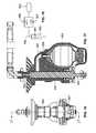
- FIG. 1is a perspective view of a planting row unit attached to a towing frame.
- FIG. 2is a partially sectioned side elevation of the planting row unit of FIG. 1 with the linkage that connects the row unit to the towing frame in a level position.
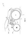
- FIG. 3is the same side elevation shown in FIG. 1 but with the linkage tilted upwardly to move the row unit to a raised position.
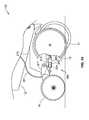
- FIG. 4is the same side elevation shown in FIG. 1 but with the linkage tilted downwardly to move the row unit to a lowered position.
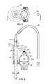
- FIG. 5is a top plan view of the hydraulic cylinder and accumulator unit included in the row unit of FIGS. 1-4 .
- FIG. 6is a vertical section taken along line 6 - 6 in FIG. 5 .
- FIG. 7is a side elevation of the unit shown in FIGS. 5 and 6 connected to a pair of supporting elements, with the support structures and the connecting portions of the hydraulic cylinder shown in section.
- FIGS. 8A and 8Bare enlarged cross sectional views of the supporting structures shown in section in FIG. 7 .
- FIG. 9is an enlarged perspective of the right-hand end portion of FIG. 1 with a portion of the four-bar linkage broken away to reveal the mounting of the hydraulic cylinder/accumulator unit.
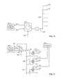
- FIG. 10is a schematic diagram of a first hydraulic control system for use with the row unit of FIGS. 1-9 .
- FIG. 11is a schematic diagram of a second hydraulic control system for use with the row unit of FIGS. 1-9 .
- FIG. 12is a diagram illustrating one application of the hydraulic control system of FIG. 11 .
- FIG. 13is a side elevation of a modified embodiment having the hydraulic control unit coupled to the closing wheels of the row unit;
- FIG. 14is a side elevation of a further modified embodiment having the hydraulic control unit coupled to the closing wheels of the row unit;
- FIG. 15is yet another modified embodiment having the hydraulic control unit coupled to the closing wheels of the row unit;
- FIG. 16is a side elevation of another modified embodiment of a hydraulic control unit
- FIG. 17is an enlarged section taken along the line 17 - 17 in FIG. 16 ;
- FIG. 18is a schematic diagram of the hydraulic circuit in the unit of FIGS. 16 and 17 .
- FIG. 19is a perspective view of a standard configuration of a hydraulic system.
- FIG. 20Ais an exploded view of a standard configuration of a hydraulic assembly.
- FIG. 20Bis an assembled perspective view of FIG. 20A .
- FIG. 21is a perspective view of a hose connection manifold.
- FIG. 22Ais a top cross-sectional view of FIG. 20B .
- FIG. 22Bis a side cross-sectional view of FIG. 20B .
- FIG. 23is a perspective view of an alternative configuration of the hydraulic system of FIG. 19 .
- FIG. 24Ais an exploded view of an alternative configuration of a hydraulic assembly.
- FIG. 24Bis an assembled perspective view of FIG. 24A .
- FIG. 25Ais a perspective view of a control manifold.
- FIG. 25Bis a left cross-sectional view of the control manifold of FIG. 25A .
- FIG. 25Cis a right cross-sectional view of the control manifold of FIG. 25A .
- FIG. 26is a top plan view of a hydraulic cylinder for a row unit.
- FIG. 27Ais a vertical section taken along line 27 A- 27 A in FIG. 26 .
- FIG. 27Bis an enlarged view of a ram leading area that is shown in FIG. 27A .
- FIG. 28Ais a side elevation of a hydraulic control system with double-acting ram for use with a row unit.
- FIG. 28Bis an enlarged view illustrating a hydraulic control unit of the hydraulic control system of FIG. 28A .
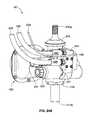
- FIG. 29is a perspective view of an agricultural opener device with integrated controller.
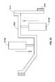
- FIG. 30is a schematic diagram of a hydraulic control system having integrated controllers in one or more row units.
- FIG. 31is a schematic diagram of a hydraulic control system for use with a row unit.
- FIG. 32is a partial perspective of a linkage assembly with two actuators for controlling a row unit.
- FIG. 33is a side illustration of the linkage assembly of FIG. 32 .
- FIG. 34illustrates an actuator having two energy storage devices.
- FIG. 35illustrates a tractor towing a plurality of row units having status indicators.
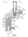
- FIG. 36Ais a cross-sectional view of an assembly having a hydraulic actuator and a manifold with a solenoid cartridge valve configuration, the actuator shown in a first position.
- FIG. 36Billustrates the assembly of FIG. 36A with the actuator shown in a second position.
- FIG. 37illustrates a portion of the manifold of FIG. 36A with a plugged configuration.
- a planting row unit 10includes a furrow-opening device for the purpose of planting seed or injecting fertilizer into the soil.
- the furrow-opening deviceis a V-opener 11 formed by a pair of conventional tilted discs depending from the leading end of a row unit frame 12 .
- a conventional elongated hollow towing frame 13(typically hitched to a tractor by a draw bar) is rigidly attached to the front frame 14 of a conventional four-bar linkage assembly 15 that is part of the row unit 10 .
- the four-bar (sometimes referred to as “parallel-bar”) linkage assembly 15is a conventional and well known linkage used in agricultural implements to permit the raising and lowering of tools attached thereto.
- the V-opener 11penetrates the soil to form a furrow or seed slot. Other portions of the row unit 10 then deposit seed in the seed slot and fertilizer adjacent to the seed slot, and close the seed slot by distributing loosened soil into the seed slot with a pair of closing wheels 16 .
- a gauge wheel 17determines the planting depth for the seed and the height of introduction of fertilizer, etc.
- Bins 18 a and 18 b on the row unitcarry the chemicals and seed which are directed into the soil.
- the planting row unit 10is urged downwardly against the soil by its own weight, and, in addition, a hydraulic cylinder 19 is coupled between the front frame 14 and the linkage assembly 15 to urge the row unit 11 downwardly with a controllable force that can be adjusted for different soil conditions.
- the hydraulic cylinder 19may also be used to lift the row unit off the ground for transport by a heavier, stronger, fixed-height frame that is also used to transport large quantities of fertilizer for application via multiple row units.
- the hydraulic cylinder 19is shown in more detail in FIGS. 5 and 6 .
- Pressurized hydraulic fluid from the tractoris supplied by a hose 20 to a port 21 that leads into a matching port 22 of a housing 23 that forms a cavity 24 of a hydraulic cylinder containing a ram 25 .
- the housing 23also forms a side port 26 a that leads into cavity 26 b that contains a gas-charged hydraulic accumulator 27 .
- the lower end of the cavity 24is formed by the top end surface of the ram 25 , so that the hydraulic pressure exerted by the hydraulic fluid on the end surface of the ram 25 urges the ram downwardly (as viewed in FIG. 6 ), with a force determined by the pressure of the hydraulic fluid and the area of the exposed end surface of the ram 25 .
- the hydraulic fluidthus urges the ram 25 in an advancing direction (see FIG. 4 ).
- the hydraulic cylinder 19 and the accumulator 27are mounted as a single unit on the front frame 14 , with the lower end of the ram 25 connected to a cross bar 30 that is joined at one end to a vertical link 31 .
- the upper and lower ends of the link 31are pivotably attached to upper and lower links 15 a and 15 b , respectively, on one side of the four-bar linkage 15 .
- the other end of the cross bar 30is angled upwardly and pivotably attached to the upper link 15 c on the opposite side of the four-bar linkage 15 .
- the accumulator 27includes a diaphragm 28 that divides the interior of the accumulator into a hydraulic-fluid chamber 29 a and a gas-filled chamber 29 b , e.g., filled with pressurized nitrogen.
- FIG. 2shows the ram 25 in a position where the diaphragm 28 is not deflected in either direction, indicating that the pressures exerted on opposite sides of the diaphragm are substantially equal.
- FIG. 3the ram 25 has been retracted by upward movement of the row unit, and the diaphragm 28 is deflected downwardly by the hydraulic fluid forced into the accumulator 27 by the retracting movement of the ram 25 .
- FIG. 3shows the ram 25 in a position where the diaphragm 28 is not deflected in either direction, indicating that the pressures exerted on opposite sides of the diaphragm are substantially equal.
- FIG. 3the ram 25 has been retracted by upward movement of the row unit, and
- the ram 25has been withdrawn to its most retracted position, which can occur when the row unit encounters a rock or other obstruction, for example.
- the row unitis in its uppermost position.
- retracting movement of the ram 25is limited by engagement of stops 40 , 42 on the lower links of the four-bar linkage 15 , with the row unit frame 12 .
- Retracting movement of the ram 25reduces the volume of the cavity 24 (see FIG. 3 ), which causes a portion of the fixed volume of hydraulic fluid in the cylinder 19 to flow into the chamber 29 a of the accumulator 27 , causing the diaphragm 28 to deflect to the position illustrated in FIG. 3 .
- This deflection of the diaphragm 28 into the chamber 29 bcompresses the gas in that chamber.
- the hydraulic fluidTo enter the chamber 29 a , the hydraulic fluid must flow through a port 32 in the top of the accumulator 27 , which limits the rate at which the hydraulic fluid flows into the accumulator.
- This controlled rate of flow of the hydraulic fluidhas a damping effect on the rate at which the ram 25 retracts or advances, thereby avoiding sudden large movements of the moving parts of the row unit, including the V-opener 11 . This effect also minimizes vibration to improve accuracy of seed metering.
- the single unitary housing 23forms both the cavity 26 b that contains the accumulator 27 and the cavity 24 of the hydraulic cylinder 19 and the fluid passageway 24 that connects the cavity 24 of the hydraulic cylinder 19 to the cavity 27 of the accumulator.
- the accumulator 27which is by definition an energy storage device, to be mounted in a fully enclosed and safe housing.
- the accumulator 27can be securely mounted to avoid puncture or rapid discharge (if it comes loose), or damage from hitting another part of the implement or a foreign object.
- the integrated cylinder and accumulatoris also a convenient single package for installation and replacement and minimizes the number of hydraulic hoses and adapters (potential leakage points).
- FIGS. 7 , 8 A and 8 Billustrate in more detail how the illustrative hydraulic cylinder/accumulator unit is attached to the front frame 14 and the linkage assembly 15 .
- the top of the unitary housing 23forms a stem 41 that projects upwardly through a hole 51 in a bracket 50 attached to the front frame 14 .
- the outer surface of the stem 41is threaded to receive a nut 52 that connects the housing 23 to the bracket 50 .
- the hole 51is oversized and a rubber washer is installed on the stem 41 between the nut 52 and the bracket 50 to allow a limited amount of tilting movement of the housing relative to the bracket 50 .
- the housing 23forms a shoulder 43 that engages a conical bearing ring 53 that also engages a mating lower surface of a washer 54 .
- the housing 23can be tilted relative to the axis of the hole 51 , with the shoulder 43 sliding over the lower surface of the bearing ring 53 .
- a similar arrangementis provided at the lower end of the ram 25 , where a stem 60 extends downwardly through a hole 61 in the cross bar 30 that is pivotably attached to the linkage assembly 15 .
- a nut 62is threaded onto the stem 60 to connect the ram to the cross bar 30 .
- the hole 61is oversized and a rubber washer is installed on the stem 60 between the nut 62 and the cross bar 30 to allow a limited amount of tilting movement of the ram 25 relative to the cross bar 30 .
- a flange 63 on the ram 25forms a curved conical surface 64 that engages a mating surface of a curved conical bearing ring 65 that also engages a mating upper surface of a washer 66 .
- the ram 25can be tilted relative to the axis of the hole 61 , with the flange 63 sliding over the upper surface of the bearing ring 65 .
- the use of a hydraulic systempermits on-the-go adjustments to be made very rapidly because the hydraulic fluid is incompressible and therefore acts more directly than an air system.
- hydraulic fluidstypically operate at higher pressures, which allows greater changes in applied forces.
- the accumulator 27allows the fluid system to flex and float with the changing terrain and soil conditions.
- the accumulator 27is preferably centrally mounted so that when any single row unit moves over an obstruction, the down-pressure cylinder 19 moves to displace the hydraulic fluid along a common set of lines connecting all row units.
- the gas in the accumulatoris compressed at the same time, allowing for isolation among the row units so that upward movement of one row unit does not cause downward movement of other row units.
- the illustrative hydraulic ramis single-acting, it is also possible to use a double-acting ram, or a single-acting ram in combination with a return spring.
- the compact hydraulic cylinder/accumulator unitcan conveniently mounted to the same brackets that are provided in many row units for mounting an air bag, to control the down pressure on the row unit.
- the brackets 50 and 51 on which the hydraulic cylinder/accumulator is mountedare the brackets that are often connected to an air bag, and thus the same row unit can be used interchangeably with either an air bag or the hydraulic cylinder/accumulator to control the down pressure on the row unit.
- FIG. 10is a schematic of a hydraulic control system for supplying pressurized hydraulic fluid to the cylinders 19 of multiple row units.
- a source 100 of pressurized hydraulic fluidtypically located on a tractor, supplies hydraulic fluid under pressure to a valve 101 via supply line 102 and receives returned fluid through a return line 103 .
- the valve 101can be set by an electrical control signal S 1 on line 104 to deliver hydraulic fluid to an output line 105 at a desired constant pressure.
- the output lineis connected to a manifold 106 that in turn delivers the pressurized hydraulic fluid to individual feed lines 107 connected to the ports 21 of the respective hydraulic cylinders 19 of the individual row units.
- the valve 101is turned off, preferably by a manually controlled on/off valve V, after all the cylinders 19 have been filled with pressurized hydraulic fluid, to maintain a fixed volume of fluid in each cylinder.
- FIG. 11is a schematic of a modified hydraulic control system that permits individual control of the supply of hydraulic fluid to the cylinder 19 of each separate row unit via feed lines 107 connected to the ports 21 of the respective cylinders 19 .
- Portions of this system that are common to those of the system of FIG. 10are identified by the same reference numbers.
- the difference in this systemis that each separate feed line 107 leading to one of the row units is provided with a separate control valve 110 that receives its own separate control signal on a line 111 from a controller 112 .
- This arrangementpermits the supply of pressurized hydraulic fluid to each row unit to be turned off and on at different times by the separate valve 110 for each unit, with the times being controlled by the separate control signals supplied to the valves 110 by the controller 112 .
- the individual valves 110receive pressurized hydraulic fluid via the manifold 106 , and return hydraulic fluid to a sump on the tractor via separate return line 113 connected to a return manifold 114 connected back to the hydraulic system 100 of the tractor.
- FIG. 12illustrates on application for the controllable hydraulic control system of FIG. 11 .
- Modern agricultural equipmentoften includes GPS systems that enable the user to know precisely where a tractor is located in real time.
- GPS systemsthat enable the user to know precisely where a tractor is located in real time.
- each planting row unit 120can be turned off just as it enters the headland 122 , to avoid double-planting while the tractor 121 makes a turn through the headland.
- the hydraulic cylinder 19 of each row unitcan also be separately controlled to turn off the supply of pressurized hydraulic fluid at a different time for each row unit, so that each row unit is raised just as it enters the headland, to avoid disrupting the rows already planted in the headland.
- FIG. 11One benefit of the system of FIG. 11 is that as agricultural planters, seeders, fertilizer applicators, tillage equipment and the like become wider with more row units on each frame, often 36 30-inch rows or 54 20-inch rows on a single 90-foot wide toolbar, each row unit can float vertically independently of every other row unit. Yet the following row units still have the down force remotely adjustable from the cab of the tractor or other selected location. This permits very efficient operation of a wide planter or other agricultural machine in varying terrain without having to stop to make manual adjustment to a large number of row units, resulting in a reduction in the number of acres planted in a given time period. One of the most important factors in obtaining a maximum crop yield is timely planting.
- each row unitor group of units
- the ability to quickly release all down force on the row unit when approaching a wet spot in the fieldone can significantly increase the planter productivity or acres planted per day, thereby improving yields and reducing costs of production.
- the toolbar-frame-mounted row unitpermits the planter row unit following independently behind to use less down force for its function, resulting in more uniform seed depth control and more uniform seedling emergence. More uniform seedling stands usually result in higher yields than less uniform seedling stands produced by planters with less accurate row cleaner ground following.
- FIGS. 13-15illustrate modified embodiments in which the hydraulic cylinder 200 urges the closing wheels 16 downwardly with a controllable force that can be adjusted for different conditions.
- pressurized hydraulic fluid from the tractoris supplied by a hose 201 to a port 202 of a housing 203 that forms a cavity of a hydraulic cylinder 204 containing a ram 205 .
- the housing 203also forms a side port 206 that leads into a cavity 207 that contains a gas-charged hydraulic accumulator 208 .
- the lower end of the cavity 204is formed by the top end surface of the ram 205 , so that the hydraulic pressure exerted by the hydraulic fluid on the end surface of the ram 205 urges the ram downwardly (as viewed in FIG. 13 ), with a force determined by the pressure of the hydraulic fluid and the area of the exposed end surface of the ram 205 .
- the hydraulic fluidthus urges the ram 205 in a downward direction.
- the hydraulic cylinder 204 and the accumulator 208are pivotably mounted as a single unit on the row unit frame 210 , with the lower end of the ram 205 pivotably connected to a linkage 211 that carries the closing wheels 16 .
- advancing movement of the ram 205 in the cylinder 204tilts the linkage 211 downwardly, thereby urging the closing wheels 16 downwardly.
- retracting movement of the ram 205tilts the linkage 211 upwardly, thereby raising the closing wheels 16 .
- FIG. 14illustrates an arrangement similar to FIG. 13 except that the hydraulic cylinder 204 is charged with a pressurized gas in chamber 212 on the side of the ram 205 that is not exposed to the pressurized fluid from the hose 201 .
- the hydraulic cylinder 204is positioned such that advancing movement of the ram 205 in the cylinder 204 tilts the linkage 211 upwardly, thereby raising the closing wheels 16 .
- the hydraulic control unithas an added biasing element 220 on the side of the ram 205 that is not exposed to the pressurized hydraulic fluid.
- This biasing element 220may be in addition to, or in place of, pressurized gas in the hydraulic cylinder 204 .
- the biasing element 220may be formed by various types of mechanical springs, such as a compressed coil spring, or may be pressurized air, nitrogen or other gas.
- FIGS. 16-18illustrate a modified hydraulic control unit that includes a hydraulic cylinder 300 containing a ram 301 that can be coupled at its lower end to a device on which the down pressure is to be controlled. Pressurized hydraulic fluid is supplied to the upper end of the cylinder 301 through a port 304 .
- the cylinder 300includes a side port 302 leading to an accumulator 303 of the type described above in connection with FIGS. 5 and 6 .
- the entry port 305 to the accumulator 303is equipped with a check valve 306 and restriction 307 as illustrated in FIG. 18 .
- hydraulic fluidflows from the cylinder 300 into the accumulator 303 via the restriction 307 .
- the restrictionacts as a damper to reduce the shock on the equipment and avoid excessive upward movement of the ram 301 .
- hydraulic fluidflows from the accumulator back into the cylinder 300 via the check valve 306 , which allows unrestricted flow in this direction so that the controlled device quickly re-engages the ground with the down pressure exerted by the hydraulic fluid on the upper end of the ram 301 .
- the check valve unitcan be easily installed in the accumulator entry port 305 . Additionally, the check valve unit can have an orifice system that is bidirectional for damping motion, both in and out.
- row unitrefers to a unit that is attached to a towing frame in a way that permits the unit to move vertically relative to the towing frame and other units attached to that same towing frame. Most row units are equipped to form, plant and close a single seed furrow, but row units are also made to form, plant and close two or more adjacent seed furrows.
- a hydraulic system 400includes a hydraulic assembly 401 , a front frame 404 , and a four-bar linkage assembly 406 .
- the four-bar linkage assembly 406is generally similar to the four-bar linkage assembly 15 described above in reference to FIGS. 1-9 .
- the four-bar linkage assembly 406includes a pair of parallel lower links 408 a , 408 b , a pair of parallel upper links 410 a , 410 b , and a cross bar 412 .
- the hydraulic assembly 401is rigidly attached to the four-bar linkage assembly 406 on a row-unit side, and the front frame 404 is pivotably attached to the four-bar linkage assembly 406 on a towing side.
- the hydraulic assembly 401includes a hydraulic cylinder 402 , an accumulator protective cover 420 , and a hose connection manifold 424 .
- the hydraulic cylinder 402is generally similar to the hydraulic cylinders 19 , 204 described above in reference to FIGS. 1-9 and 13 - 18 , and includes an upper end 413 a and a lower end 413 b .
- the upper endis mounted to a bracket 414 of the linkage assembly 406
- the lower end 413 bis mounted to the cross bar 412 of the linkage assembly 406 .
- a gland and securing nut 418(with internal seals) is interposed at the lower end 413 b between the hydraulic cylinder 402 and the cross bar 412 .
- the accumulator protective cover 420is mounted adjacent to and between a left upper link 410 b and the hydraulic cylinder 402 .
- the accumulator protective cover 420shields from environmental contaminants and physical damage an accumulator 422 (shown in FIG. 20A ).
- the accumulator protective cover 420itself is provided with protection from physical damage, e.g., caused by debris, rocks, etc., by being located between the pair of upper links 410 a , 410 b .
- the upper links 410 , 410 bdo not completely shield the accumulator protective cover 420 , the upper links 410 , 410 b provide some protection from physical damage while, simultaneously, allowing ease of access for servicing and/or replacing the accumulator 422 .
- the hose connection manifold 424which is described in more detail below in reference to FIG. 21 , is mounted adjacent to and between a right upper link 410 a and the hydraulic cylinder 402 .
- the hose connection manifold 424is configured such that it does not interfere with any of the other components of the hydraulic system 400 , including the right upper link 410 a , the hydraulic cylinder 402 , and the accumulator protective cover 420 .
- the hose connection manifold 424is coupled at a distal end to a pair of hydraulic fluid hoses, including an inlet hose 426 and an outlet hose 428 .
- the inlet hose 426receives and delivers hydraulic fluid from an adjacent row unit, and the outlet hose 428 connects to another adjacent row unit.
- the attachment of the hoses 426 , 428 to the hose connection manifold 424in a position that is spaced away from the relatively more-cluttered area of the hydraulic cylinder 402 and bracket 414 , facilitates easy field servicing of the hoses 426 , 428 .
- a usercan easily couple/uncouple the hoses 426 , 428 to/from the hose connection manifold 424 by having a clear path directly to the hose connection manifold 424 .
- the accumulator protective cover 420includes a right cover 420 a and a left cover 420 b that are fastened to each other via a plurality of small nuts 434 and bolts 436 .
- the accumulator 422Enclosed within the accumulator protective cover 420 is the accumulator 422 , which has an accumulator end 430 that is inserted into a accumulator receiver 432 of the hydraulic cylinder 402 .
- the accumulator receiver 432extends from a main body 433 of the hydraulic cylinder 402 a sufficient distance to permit the mounting of the accumulator protective cover 420 without interfering with the hose connection manifold 424 (as further illustrated in FIG. 22A ).
- the main body 433 of the hydraulic cylinder 402receives a spherical rod 438 for axial mounting below the accumulator receiver 432 .
- the gland 418is threaded into the hydraulic cylinder 402 after the spherical rod 438 is installed on the hydraulic cylinder 402 .
- the gland 418contains internal seals and wear rings to hold pressure and seal out contaminants.
- the hydraulic cylinder 402further includes a mounting interface 440 extending from the main body 433 in an opposite direction relative to the accumulator receiver 432 .
- the hose connection manifold 424is mounted directly to the mounting interface 440 via a plurality of long bolts 442 that are received, respectively, in a plurality of threaded holes 444 .
- An O-ring seal 441is positioned between the control manifold 424 and the hydraulic cylinder 402 to prevent leakage of hydraulic fluid.
- the hose connection manifold 424has a mounting face 456 (shown in FIG. 21 ) that is aligned, when mounted, in contact with a receiving face 443 of the mounting interface 440 .
- the mounting face 456 of the hose connection manifold 424 and the receiving face 443 of the mounting interface 440are configured such that they are complementary mating faces with the O-ring seal 441 holding pressure between the components.
- the mounting interface 440further facilitates a modular exchange between hose connection manifolds of different types.
- the hose connection manifold 424is an example of a standard configuration in which the manifold functions solely to attach hydraulic hoses and to circulate hydraulic fluid between the hydraulic source and the hydraulic cylinder 402 .
- the same mounting interface 440(without reliance on additional components or tools) is used to attach a manifold of a different type.
- This modular exchange between different manifold typesis beneficial for quick and easy replacement of the manifolds based on current planting needs, which can quickly change in real time due to weather conditions, terrain conditions, etc.
- a pair of hose ends 446 , 448are attached to the hose connection manifold 424 at a distal end 450 for coupling the inlet and outlet hoses 426 , 428 .
- an inlet hose-end 446is coupled to the inlet hose 426 and an outlet hose-end 446 is coupled to the outlet hose 428 .
- the hose ends 446 , 448are attached to the distal end 450 in a generally parallel configuration relative to a central axis of the hydraulic cylinder 402 .
- the attachment configuration of the hose ends 446 , 448 to the hose connection manifold 424facilitates easy access and servicing of the inlet and outlet hoses 426 , 428 .
- the hose connection manifold 424is a valve-less manifold that lacks a control valve or a control module (in contrast to the integrated control manifold 524 discussed below in reference to FIGS. 23-25C ).
- the hose connection manifold 424has a mounting end 452 that is separated from the distal end 450 by a manifold arm 454 .
- the manifold arm 454includes a curved section that offsets the mounting face 456 of the mounting end 452 by a distance D from an exterior surface 466 of the distal end 450 .
- the offset distance Dis helpful in minimizing space requirements for mounting the hose connection manifold 424 within the space defined by the upper links 410 , 410 b of the linkage assembly 406 .
- the manifold arm 454is positioned generally parallel to the accumulator 422 .
- the mounting face 456includes a plurality of mounting holes 458 arranged in a concentric pattern around a central hydraulic hole 459 , through which hydraulic fluid is delivered to the hydraulic cylinder 402 .
- the pattern of the mounting holes 458matches a pattern of the threaded holes 444 of the mounting interface 440 .
- the hydraulic hole 459is internally connected to an inlet port 460 and an outlet port 462 via an internal channel 464 (illustrated in FIG. 22A ).
- the inlet port 460is adapted to receive the inlet hose-end 446 , to which the inlet hose 426 is coupled
- the outlet port 462is adapted to receive the outlet hose-end 446 , to which the outlet hose 428 is coupled.
- the inlet and outlet ports 460 , 462are aligned with a central axis of the internal channel 464 and are oriented perpendicular to the orientation of the hydraulic hole 459 . Additionally, the spacing between the inlet port 460 and the outlet port 462 facilitates parallel coupling of the two hose ends 446 , 448 adjacent to each other.
- the configuration of the hydraulic assembly 401facilitates delivery of hydraulic fluid to the hydraulic cylinder 402 in a relatively space-constrained environment while still providing easy access to main components, including the accumulator 422 and the hose connection manifold 424 , for service and replacement.
- hydraulic fluidcirculates unrestricted between the hose connection manifold 424 , the hydraulic cylinder 402 , and the accumulator 422 via the internal channel 464 .
- the geometric configuration of the hose connection manifold 424facilitates mounting the accumulator protective cover 420 close to the distal end 450 of the hose connection manifold 424 at a relatively small distance Z, thus minimizing required mounting space, without causing interference between the hose connection manifold 424 and the accumulator protective cover 420 .
- the distal end 450is further defined by a distance X that separates two extreme points of a central axis of the internal channel 464 .
- distance Xis defined by a point of the central axis near the distal end 450 and a point of the central axis near the mounting end 452 .
- the inlet hose 426 and the outlet hose 428can be easily and quickly removed, in the field, based at least on their parallel upward attachment to the hose connection manifold 424 .
- the inlet hose 426 and the outlet hose 428can be daisy chained when using a typical side-by-side arrangement of row units.
- a first row unitis connected directly to the hydraulic source via its inlet hose and directly to the inlet port of an adjacent second row unit via its outlet hose.
- the second row unitreceives hydraulic fluid, indirectly, from the hydraulic source via the first row unit.
- the second row unitis further daisy chained to an adjacent third row unit such that the outlet hose of the second row unit is directly connected to the inlet port of the third row unit.
- This type of daisy-chain configurationcan continue with dozens of row units.
- one of the two ports 460 , 462is plugged and a tee is placed in front of the row unit such that a single hose is connected to the hydraulic cylinder 402 .
- the hose connection manifold 424has been replaced with the integrated control manifold 524 that includes both an electronic control module 525 and a connection manifold 527 (both shown in FIGS. 24A and 24B ).
- the control manifold 524is configured to fit within the upper links 410 a , 410 b next to the accumulator protective cover 420 , similar to the hose connection manifold 424 .
- the control manifold 524does not interfere with any components of the hydraulic system 400 .
- control manifold 524is further connected to a control signal wire 529 for receiving control signals from a central processing unit.
- each row unit of a plurality of adjacent row unitshas its own pressure control valve. Assuming that the control manifold 524 is mounted in each of the plurality of row units, the down pressure in each row unit can be individually controlled. To achieve individual control, both the inlet hose 426 and the outlet hose 428 of each row unit are connected to the hydraulic source in parallel. For example, the inlet hose of a first row unit is connected to the tractor for supplying constant pressure to the first row unit, and the outlet hose of the first row unit is also connected to the tractor for returning hydraulic fluid from the first row unit.
- the inlet hose of a second row unitis connected to the tractor for supplying constant pressure to the second row unit, and the outlet hose of the second row unit is also connected to the tractor for returning hydraulic fluid from the second row unit.
- the pressure in the first and second row unitscan be independently controlled.
- the control manifold 524is mounted to the hydraulic cylinder 402 using the same long bolts 442 , which are fastened to the threaded holes 444 .
- the control manifold 524has a mating face 556 (shown in FIGS. 25A-25C ) that is generally similar (if not identical) to the mating face 456 of the hose connection manifold 424 .
- the mating face 556is configured as a mating face for facilitating attachment of the control module 524 to the mounting interface 440 (similar to the attachment of the hose connection manifold 424 to the mounting interface 440 ).
- An O-ring seal 541is positioned between the control manifold 524 and the hydraulic cylinder 402 to prevent leakage of hydraulic fluid.
- the hose ends 446 , 448are received in respective inlet and outlet ports 560 , 562 for facilitating coupling of the hoses 426 , 428 to the control module 542 .
- the inlet and outlet ports 460 , 462 of the hose connection manifold 424are oriented perpendicular to (not parallel to) the central axis of the hydraulic cylinder 402 . Nevertheless, a user can still reach with relative ease the connection between hoses 426 , 428 and the ports 560 , 562 for service-related needs.
- the control module 525includes a hydraulic valve cartridge 531 for reducing and/or relieving pressure in hydraulic cylinder 402 .
- the valve cartridge 531is enclosed within the control module 525 and has one end inserted in a cartridge port 533 of the connection manifold 527 .
- the valve cartridge 531reduces pressure in the hydraulic cylinder 402 and, optionally, acts as a relief valve relieving any shocks or surges that may occur between the hydraulic source and the hydraulic cylinder 402 .
- the control module 525optionally includes a pressure transducer 535 and/or other embedded electronics.
- an integrated electronic connector 537 of the control module 525is positioned above the valve cartridge 531 for receiving electrical power via an electrical cable (not shown).
- the electronic connector 537is angled towards the accumulator protective cover 420 to provide sufficient space for connecting all the required cables and hoses to the control module 525 , e.g., the inlet and outlet hoses 426 , 428 , the control signal wire 529 , and the electrical cable.
- connection manifold 527is configured to facilitate the integral combination with the control module 525 .
- the connection manifold 527has a mounting face 556 that is aligned, when mounted with the receiving face 443 of the mounting interface 440 .
- the mounting face 556 of the connection manifold 527is generally similar (if not identical) to the mounting face 456 of the hose connection manifold 424 .
- the mounting face 556includes a plurality of mounting holes 558 arranged in a concentric pattern around a central hydraulic hole 559 , through which hydraulic fluid is delivered to the hydraulic cylinder 402 .
- the pattern of the mounting holes 558matches a pattern of the threaded holes 444 of the mounting interface 440 .
- the hydraulic hole 559is internally connected to the inlet port 560 , the outlet port 562 , the cartridge port 533 , and a transducer port 539 .
- the connection manifold 527includes the additional cartridge port 533 for coupling to the valve cartridge 531 (which controls output of fluid pressure from the hydraulic cylinder 402 ) and the transducer port 539 for coupling to the pressure transducer 535 .
- the portsare positioned along a control face 541 , which is generally perpendicular to the mounting face 556 .
- connection manifold 527 and the hose connection manifold 424share some similarities (e.g., sharing the modular mounting interface 440 ), they are different in type at least based on the connection manifold 527 being configured geometrically to facilitate the integration with the control module 525 .
- a hydraulic cylinder 619 and energy storage device 627are generally similar to the hydraulic cylinder 19 and accumulator 27 described and illustrated above in reference to FIGS. 5 and 6 .
- a single unitary housing 623forms a cavity 624 in which the hydraulic cylinder 619 and the energy storage device 627 are enclosed, at least in part.
- the hydraulic cylinder 619contains a ram 625 that advances towards a housing port 622 or retracts towards a stem 660 .
- the ram 625has a leading edge 650 near which a wear ring 652 is mounted.
- the wear ring 652is mounted on the ram 625 concentric with a central axis Z of the ram 625 and in physical contact (or close to being in physical contact) with a cylinder wall 654 .
- the wear ring 652can be a seal or some other component that can provide a barrier zone between the ram 625 and the cylinder wall 654 .
- the wear ring 652can have a cylindrical cross-sectional profile (as illustrated in FIG. 27B ) or any other cross-sectional profile.
- the wear ring 652guides the ram 625 within the cylinder wall 654 of the hydraulic cylinder 619 , absorbing transverse forces.
- the wear ring 652further prevents (or reduces) metal-to-metal contact between the ram 625 and the cylinder wall 654 and, thus, optimizes the performance of the hydraulic cylinder 619 .
- one benefit of the wear ring 652is that it prevents or reduces wear of the ram 625 due to frictional contact with the cylinder wall 654 .
- Another benefit of the wear ring 652is that it tends to act as a seal component (although not necessarily specifically intended to be a seal component).
- tight tolerances between the ram 625 and the cylinder wall 654help achieve a sealing function that prevents, or greatly reduces, undesired fluid flow between the ram 625 and the cylinder wall 654 .
- the tight tolerancescan range between 0.01 inches and 0.03 inches.
- the ram 625further includes a plurality of intersecting internal passageways, including an axial passageway 660 and a radial passageway 662 .
- the axial passageway 660starts at the leading edge 650 and continues partially within the ram 624 , along the central axis Z, until it intersects with the radial passageway 662 .
- the radial passageway 662extends perpendicular to the central axis Z between the central axis Z and a peripheral wall of the ram 625 .
- the internal passageways 660 , 662provide a dampening feature to the hydraulic cylinder 610 .
- the internal passageways 660 , 662equalize pressure on either side of the wear ring 652 (which tends to act as a seal at high-speed ram velocities).
- the hydraulic cylinder 619is intended to generate pressure
- the internal passageways 660 , 662integrate into the hydraulic cylinder 619 damping to control unwanted movement and or pressure.
- the internal passageway 660 , 662are helpful in preventing damage to the hydraulic cylinder 619 by controlling the damping of the hydraulic cylinder 619 .
- the internal passageways 660 , 662can be used for mounting check valves to the ram 625 .
- the check valvescan further control the damping in the hydraulic cylinder 619 .
- the internal passageways 660 , 662provide a hydraulic cylinder with an integrated damping-control system.
- a planting row unit 710is generally similar to the planting row unit 10 described above.
- the planting row unit 710includes a V-opener 711 , a row unit frame 712 , a pair of closing wheels 716 , and a gauge wheel 717 that are assembled and function similarly to the similarly numbered components of the planting row unit 10 .
- the planting row unit 710also includes a hydraulic cylinder 700 that urges the closing wheels 716 downwardly with a controllable force that can be adjusted for different conditions.
- the hydraulic cylinder 700includes a double-acting ram 705 (which further exemplifies the double-acting ram embodiment identified above in reference to the ram 25 ) that can move in opposing directions based on fluid pressure received from either a first hose 701 a or a second hose 701 b .
- hydraulic fluidis received via the hoses 701 a , 701 b to act alternately on both sides of the double-acting ram 705 and, consequently, apply alternate pressure in both directions of arrows A-A′.
- the hydraulic cylinder 700can, optionally, further includes a biasing element 720 (e.g., mechanical spring, compressed coil spring, pressurized gas) to further add pressure in addition to the pressure provided by the double-acting ram 705 .
- the biasing element 720can be added on either side of the double-acting ram 705 .
- the double-acting ram 705can provide both down pressure or up pressure, as needed, for the planting row unit 710 . For example, if additional pressure is required to cause the V-opener 711 to penetrate the soil to a required depth, down pressure would be applied. If, for example, the planting row unit 710 is too heavy and the V-opener 711 penetrates the soil in excess of the required depth, then up pressure would be applied (without requiring an additional hydraulic cylinder).
- a disk opener 800is adapted for attachment to a row unit, such as planting row unit 10 described above in reference to FIG. 1 .
- the disk opener 800includes a support 802 to which a swing arm 804 is mounted for attaching a disk 806 and a gauge wheel 808 .
- the disk 806penetrates the soil to a planting depth for forming a furrow or seed slot, as the row unit is advanced by a tractor or other towing vehicle.
- the gauge wheel 808determines the planting depth for seeds and/or height of introduction of fertilizer.
- the disk opener 800further includes a down-pressure cylinder 810 , with an integrated control valve 812 , that is mounted to a bracket 814 .
- the down-pressure cylinder 810is generally similar to the hydraulic cylinder 402 (e.g., illustrated in FIG. 19 ) and the integrated control valve 812 is generally similar to the control module 525 (e.g., illustrated in FIG. 24A ).
- the control valve 812includes a solenoid 816 that is generally similar to the electronic connector 537 (e.g., illustrated in FIG. 24A ).
- the disk opener 800includes a programmable-logic controller (PLC) or other computer control unit 818 that is also mounted to the bracket 814 .
- PLCprogrammable-logic controller
- the control unit 818is directly integrated into the control valve 812 , e.g., into the solenoid 816 .
- the control unit 818would be generally similar to the embedded electronics integrated with and described above in reference to the control module 525 .
- the control unit 818is coupled to a power supply via a control wire 820 and to the control valve 812 via a valve wire 822 .
- the control wire 820optionally functions to connect the control unit 818 with a control interface such as found in a tractor.
- control unit 818provides better, and specific, control over the control valve 812 .
- each row unit in an arrangement having a plurality of side-by-side row unitscan be individually controlled to apply a desired down pressure specific to the corresponding row unit.
- the control unit 818runs a control algorithm that takes inputs and determines an output signal for the control valve 812 .
- a hydraulic control systemsupplies pressurized hydraulic fluid to cylinders of multiple row units.
- a source 900 of pressurized hydraulic fluidtypically located on a tractor, supplies hydraulic fluid under pressure to an optional main valve 901 via a supply line 902 and receives returned fluid through a return line 903 .
- the main valve 901can be set by an electrical control signal S 1 on line 904 to deliver hydraulic fluid to an output line 905 at a desired constant pressure.
- the output line 905is connected to a manifold 906 that, in turn, delivers the pressurized hydraulic fluid to individual feed lines 907 (which are connected to ports of respective hydraulic cylinders of the individual row units).
- the main valve 901is turned off after all cylinders have been filled with pressurized hydraulic fluid to maintain a fixed volume of fluid in each cylinder.
- Each of the individual feed lines 907leads to one of the row units and is provided with a separate control valve 910 that receives its own separate control signal on a line 911 from a respective controller 912 (which is integrated in the respective row unit as described above in reference to FIGS. 24A and 30 ).
- the separate control valve 910is provided in addition to or instead of the valve 901 . This arrangement permits the supply of pressurized hydraulic fluid to each row unit to be turned off and on at different times by the separate control valve 910 for each row unit, with the times being controlled by the separate control signals supplied to the valves 910 by the respective controllers 912 .
- the individual valves 910receive pressurized hydraulic fluid via the manifold 906 , and return hydraulic fluid to the tractor via separate return lines 913 connected to a return manifold 914 , which is connected back to the hydraulic system 900 of the tractor.
- one or more of the individual integrated controllers 912are connected to a main controller 915 that provides control input for at least one of the integrated controllers 912 .
- the alternative configurationincludes a tractor 950 that generates hydraulic auxiliary power bifurcated into two power subsets: a tractor hydraulic system (THS) 952 and a tractor power take-off (PTO) 954 .
- the tractor hydraulic system 952is coupled to a hydraulically-driven electrical generator 956 for generating electricity for row unit components such as the control valves 910 and/or other control modules (e.g., controllers 912 , 915 ).
- the tractor PTO 954is mechanical power that runs a hydraulic pump 958 to provide mechanical power for row unit components such as hydraulic cylinders connected to the individual feed lines 907 .
- Providing both the hydraulic system 952 and the tractor PTO 954helps provide additional electrical power for electrical components that previously were not included in an agricultural system. For example, adding controllers 912 , 915 and control valves 910 to each row unit results in an increased need of electrical power relative to agricultural systems that, for example, lacked individual row-unit control.
- the electrical generator 956compensates for and provides the required increased electricity.
- a hydraulic cylinder systemincludes two hydraulic cylinders 1019 a , 1019 b , instead of a single actuator as described above in reference to the hydraulic cylinder 19 (which is illustrated, for example, in FIG. 9 ).
- Each of the hydraulic cylinders 1019 a , 1019 bis generally similar to the hydraulic cylinder 19 .
- this alternative embodimentillustrates coupling the two hydraulic cylinders 1019 a , 1019 b between a front frame 1014 and a linkage assembly 1015 .
- the hydraulic cylinders 1019 a , 1019 bare both mounted at one end to a cross bar 1030 , which has been modified in this illustrative embodiment and relative to the cross bar 30 of FIG. 9 to have generally a Z-shape. Specifically, a first hydraulic cylinder 1019 a is mounted such that it can apply down pressure D to the row unit and a second hydraulic cylinder 1019 b is mounted such that it can apply up pressure U to the row unit.
- the row unitcan be controlled both up and down with more precision.
- the controlled row unitmay have a heavy weight that results in a furrow depth exceeding the desired planting depth.
- the second hydraulic cylinder 1019 bis used to raise the row unit such that the shallower depth is achieved.
- the second hydraulic cylinder 1019 bacts to subtract (or counter) at least some of the row-unit weight.
- the first hydraulic cylinder 1019 ais used to lower the row unit such that the deeper depth is achieved. As such, the first hydraulic cylinder 1019 a acts to artificially add weight to the row unit.
- a hydraulic cylinder 1119includes two storage energy devices, which are illustrated in the form of a first accumulator 1127 a and a second accumulator 1127 b .
- Each of the two accumulators 1127 a , 1127 bis generally similar to the accumulator 27 (illustrated, for example, in FIG. 6 ).
- the hydraulic cylinder 1119includes a ram 1125 that acts similar to the double-acting ram 705 illustrated in FIGS. 28A and 28B .
- the ram 1125can provide both down pressure or up pressure, as needed, for a planting row unit (e.g., planting row unit 710 ).
- the accumulators 1127 a , 1127 bact as shock absorbers to help relieve pressure based on the direction of the applied pressure by the double-acting ram 1125 .
- the first accumulator 1127 arelieves pressure when the double-acting ram 1125 applies pressure in a first direction D 1 (e.g., down pressure)
- the second accumulator 1127 brelieves pressure when the double-acting ram 1125 applies pressure in a second direction D 2 (e.g., up pressure).
- this hydraulic cylinder 1119as a compact hydraulic down-force unit with integral accumulators 1127 a , 1127 b on each row unit, provides the advantages of quick response and remote adjustability of a hydraulic down-force and up-force control system. If an obstruction requires quick movement, oil can flow quickly and freely between the force cylinder 1119 and the respective adjacent accumulator 1127 a , 1127 b , without exerting force on other actuators in the system.
- a controllable hydraulic control system 1200includes a plurality of row units 1202 that are towed by a vehicle 1204 through a field.
- Each of the row units 1202includes a status indicator 1206 for signaling performance-related issues.
- the status indicators 1206are light-emitting diodes (LED) that provide a easily discernable way to visually inspect the performance of the row units 1202 .
- the LED status indicators 1206can flash a red color R to indicate improper tilling or a malfunction. If everything performs as intended, the status indicators 1206 can flash a green color G.
- the status indicator 1206can be a single (larger) LED or a plurality of LEDs of various sizes. Alternatively, the status indicator 1206 can include in addition to or instead of the LED an audible indicator to signal a malfunction or other condition of the system 1200 .
- the status indicators 1206can be integrated with control electronics of the row units 1202 (e.g., control module 525 illustrated in FIG. 23 ) and can provide a status-check of the electronics.
- the status indicators 1206are attached to each individual row unit 1202 to provide a person that is far away from the row units 1202 a quick visual check on the performance status of the system 1200 , including the performance status of an electronics controller.
- the status indicators 1206are particularly helpful in a system 1200 that is a human-less farming system.
- the human-less farming systemis a system in which robotic machines are moving about in the field to perform tilling, planting, and/or other agricultural functions. Such a system is monitored by a farm manager that is standing, for example, a quarter-mile away from the system.
- the status indicators 1206provide the farm manager with quick and easy visual signals that indicate the performance of the system.
- the system 1200further emits a wireless signal 1208 for communicating status performance to an online monitoring system.
- the performance of the system 1200can be, then, evaluated using an electronic device such as a smartphone.
- an assembly 1300includes a hydraulic actuator 1302 and a control manifold 1304 (also referred to as a hose connection manifold) with a solenoid cartridge valve 1306 . Except for any changes illustrated in FIGS. 36A and 36B and described in more detail below, the hydraulic actuator 1302 , the control manifold 1304 , and the solenoid cartridge valve 1306 , are similar as applicable, respectively, to any of the hydraulic actuators (or cylinders), the control manifolds, and the valves described above in reference to any of FIGS. 1-35 .
- the solenoid cartridge valve 1306includes a control module having a pressure transducer, embedded electronics, and an electronic connector.
- the assembly 1300may be coupled to a linkage assembly (e.g., four-bar linkage assembly 15 , 406 , 1015 ) and attachment frame (e.g., towing frame 13 ) as described above.
- a linkage assemblye.g., four-bar linkage assembly 15 , 406 ,
- the hydraulic actuator 1302is fixedly attached to the control manifold 1304 along a welded connection 1307 .
- the hydraulic actuator 1302is removably attached to the control manifold 1304 .
- the welded connection 1307is, instead, a fastened (e.g., bolted) connection similar or identical to the embodiment described above in reference to the control manifold 524 and the hydraulic cylinder 402 illustrated in FIGS. 24A-24B .
- the control manifold 1304receives pressurized hydraulic fluid 1308 from a hydraulic fluid supply source (e.g., a tractor) via a down-pressure hose 1310 , which is connected to an inlet port 1312 .
- the down-pressure hose 1310is connected directly to the hydraulic source or indirectly, via an adjacent row unit (in an in-tandem configuration).
- the down-pressure hose 1310is connected to an adjacent hose connection manifold, which is mounted in an adjacent row unit.
- Hydraulic fluid 1308is returned to the fluid supply source (directly or indirectly) via a return-pressure hose 1314 , which is connected to an outlet port 1316 .
- the solenoid cartridge valve 1306is connected to the control manifold 1304 via a valve port 1318 .
- the valve 1306includes a spring 1320 that applies a spring force to a sliding spool 1322 .
- Several O-ring seals 1324prevent (or reduce) fluid leakage within the internal cavity of the valve port 1318 .
- the hydraulic actuator 1302applies down pressure, uplift pressure, or both to an agricultural row unit (or to specific row-unit components).
- the hydraulic actuator 1302receives the pressurized hydraulic fluid 1308 in a cavity 1326 in which a rod 1328 moves a ram 1330 that is slidable along internal walls 1327 of the cavity 1326 .
- O-ring seals 1332control fluid leakage between a down-lift cavity area 1326 a and an uplift cavity area 1326 .
- the down-lift cavity area 1326 ais coupled to an internal channel 1333 of the control manifold 1304 , which facilitates the down pressure applied by the hydraulic actuator 1302 .
- the uplift cavity area 1326includes an uplift port 1334 to which an uplift pressure hose 1336 is connected for providing the uplift pressure.
- the assembly 1300includes a plugged configuration in which the solenoid cartridge valve 1306 is now replaced by a valve port plug 1340 .
- the valve port 1318is a modular port that accepts, one at a time, either the solenoid cartridge valve 1306 or the port plug 1340 .
- the port plug 1340is a cavity plug to which a coupler adapter 1342 (such as a threaded nut) connects a pressure hose 1344 .
- the pressure hose 1344is connected in-tandem to an adjacent row unit (e.g., to an adjacent control manifold, hydraulic actuator, etc.) or directly to the fluid supply source.
- the port plug 1340includes at least one O-ring seal 134 to prevent (or greatly reduce) leakage of hydraulic fluid 1308 to the inlet port 1312 and/or the outlet port 1316 .
- the port plug 1340includes a port cavity 1340 a and a port internal wall 1340 b .
- the hydraulic fluid 1308flows through the port cavity 1340 a between the fluid source and the internal channel 1333 (towards the hydraulic actuator 1302 ).
- the plugged configuration of the assembly 1300further replaces the down-pressure hose 1310 with an inlet plug 1346 , which plugs the inlet port 1312 , and the return-pressure hose 1314 with an outlet plug 1348 , which plugs the outlet port 1316 .
- inlet channel 1350 and outlet channel 1352do not receive hydraulic fluid (except for minimal fluid that may leak past the O-ring seal 134 ).
- One advantage of the plugged configurationis that it improves electrical efficiency in a system with multiple row units. If each row unit includes one or more dedicated solenoid cartridge valves 1306 , the required electrical power for operating each valve 1306 is likely to surpass the maximum electrical capacity of the electrical source, e.g., the tractor. As such, replacement of at least some valves 1306 with a respective port plug 1340 decreases the electricity demand. The greater the number of row units, the higher the electrical demand. For example, a system with 48 row units, with each row unit having at least one valve 1306 may not be able to meet the electrical load. As such, having sections of row units that are operated by the same valve 1306 (e.g., sections of two or more row units) would help reduce the electrical load.
- an agricultural systemincludes a section that includes two row units having a first row unit positioned in-tandem with (or adjacent to) a second row unit.
- the two row unitscan be any two adjacent row units 120 , 1202 described above and illustrated in FIGS. 12 and 35 .
- the first row unithas a first manifold (which is mounted and functions as described above in reference to the control manifold 1304 ) with a valve (which can the same as or similar to the solenoid cartridge valve 1306 described above) inserted into a modular port (which can be in accordance with the valve port 1318 described above).
- the second row unithas a second manifold (which is mounted and functions as described above in reference to the control manifold 1304 ) with a removable plug (which can be in accordance with the plugs 1340 , 1346 , 1348 described above) inserted into a modular port (which can be in accordance with ports 1312 , 1316 , 1318 ).
- a second manifoldwhich is mounted and functions as described above in reference to the control manifold 1304
- a removable plugwhich can be in accordance with the plugs 1340 , 1346 , 1348 described above
- a modular portwhich can be in accordance with ports 1312 , 1316 , 1318 .
- a related advantage of the modular valve port described aboveis that users, e.g., farmers, can customize the agricultural systems, e.g., planter units, to achieve the appropriate balance between control and electrical power consumption.
- a farmercan mount to or remove from any row units the appropriate number of control valves for a particular plot of land at a particular time to achieve the required balance that will provide the desired control but without surpassing the maximum electrical capacity of the tractor.
- the farmerhas the option to decide whether to use more control valves, which will provide greater control, or less control valves, which will draw reduced electricity from the tractor or other electrical source.
- the assembly 1300has plugged configurations in which the hydraulic fluid 1308 is supplied via any of the inlet port 1312 or the outlet port 1316 .
- the port plug 1340is a plug that has no port cavity 1340 a .
- the port plug 1340is a solid plug that prevents fluid flow (in or out of the manifold 1304 ) and is optionally configured to prevent flow in one of the inlet and outlet channels 1350 , 1352 .
- either the inlet plug 1346 or the outlet plug 1348is shaped and configured similar to the port plug 1340 as described above in reference to FIG. 37 to facilitate fluid flow to the hydraulic actuator 1302 .
- either the inlet plug 1346 or the outlet plug 1348is adapted to receive the pressure hose 1344 , through which the hydraulic fluid 1308 is received into the internal channel 1333 of the manifold 1304 .
Landscapes
- Life Sciences & Earth Sciences (AREA)
- Soil Sciences (AREA)
- Environmental Sciences (AREA)
- Engineering & Computer Science (AREA)
- Mechanical Engineering (AREA)
- Lifting Devices For Agricultural Implements (AREA)
Abstract
Description
Claims (18)
Priority Applications (1)
| Application Number | Priority Date | Filing Date | Title |
|---|---|---|---|
| US14/063,180US9226440B2 (en) | 2010-09-15 | 2013-10-25 | Agricultural apparatus with hydraulic cylinder and manifold for a row unit |
Applications Claiming Priority (5)
| Application Number | Priority Date | Filing Date | Title |
|---|---|---|---|
| US12/882,627US8544397B2 (en) | 2010-09-15 | 2010-09-15 | Row unit for agricultural implement |
| US13/075,574US8544398B2 (en) | 2010-09-15 | 2011-03-30 | Hydraulic down pressure control system for closing wheels of an agricultural implement |
| US13/561,934US8776702B2 (en) | 2010-09-15 | 2012-07-30 | Hydraulic down pressure control system for an agricultural implement |
| US13/758,979US9055712B2 (en) | 2010-09-15 | 2013-02-04 | Agricultural apparatus with integrated controller for a row unit |
| US14/063,180US9226440B2 (en) | 2010-09-15 | 2013-10-25 | Agricultural apparatus with hydraulic cylinder and manifold for a row unit |
Related Parent Applications (1)
| Application Number | Title | Priority Date | Filing Date |
|---|---|---|---|
| US13/758,979Continuation-In-PartUS9055712B2 (en) | 2010-09-15 | 2013-02-04 | Agricultural apparatus with integrated controller for a row unit |
Publications (2)
| Publication Number | Publication Date |
|---|---|
| US20140048297A1 US20140048297A1 (en) | 2014-02-20 |
| US9226440B2true US9226440B2 (en) | 2016-01-05 |
Family
ID=50099265
Family Applications (1)
| Application Number | Title | Priority Date | Filing Date |
|---|---|---|---|
| US14/063,180Active2031-01-20US9226440B2 (en) | 2010-09-15 | 2013-10-25 | Agricultural apparatus with hydraulic cylinder and manifold for a row unit |
Country Status (1)
| Country | Link |
|---|---|
| US (1) | US9226440B2 (en) |
Cited By (31)
| Publication number | Priority date | Publication date | Assignee | Title |
|---|---|---|---|---|
| US20150373901A1 (en)* | 2010-09-15 | 2015-12-31 | Dawn Equipment Company | Row Unit For Agricultural Implement |
| US9615497B2 (en) | 2014-02-21 | 2017-04-11 | Dawn Equipment Company | Modular autonomous farm vehicle |
| US9668398B2 (en) | 2014-02-05 | 2017-06-06 | Dawn Equipment Company | Agricultural system for field preparation |
| US9677577B1 (en)* | 2016-12-09 | 2017-06-13 | Ellicott Dredge Enterprises, Llc | Dredge having modular hydraulic manifolds |
| US9723778B2 (en) | 2014-11-07 | 2017-08-08 | Dawn Equipment Company | Agricultural system |
| US9848522B2 (en) | 2014-11-07 | 2017-12-26 | Dawn Equipment Company | Agricultural system |
| US9861022B2 (en) | 2013-02-01 | 2018-01-09 | Dawn Equipment Company | Agricultural apparatus with hybrid single-disk, double-disk coulter arrangement |
| EP3398423A1 (en) | 2017-05-04 | 2018-11-07 | Dawn Equipment Company | System for automatically setting the set point of a planter automatic down pressure control system with a seed furrow sidewall compaction measurement device |
| US10251324B2 (en) | 2011-07-01 | 2019-04-09 | Charles H. Martin | Agricultural field preparation device |
| WO2019104344A1 (en)* | 2017-11-27 | 2019-05-31 | Robert Taylor | Systems, apparatus, and methods for transporting vessels |
| US10444774B2 (en) | 2014-11-07 | 2019-10-15 | Dawn Equipment Company | Agricultural system |
| US10477760B2 (en) | 2015-12-28 | 2019-11-19 | Underground Agriculture, LLC | Agricultural organic device for weed control |
| US10506755B2 (en) | 2010-09-15 | 2019-12-17 | Dawn Equipment Company | Agricultural systems |
| US10582653B2 (en) | 2014-11-07 | 2020-03-10 | Dawn Equipment Company | Agricultural planting system with automatic depth control |
| US10645865B2 (en) | 2017-05-04 | 2020-05-12 | Dawn Equipment Company | Agricultural row unit with automatic control system for furrow closing device |
| US10721855B2 (en) | 2014-02-05 | 2020-07-28 | Dawn Equipment Company | Agricultural system for field preparation |
| US10912246B2 (en) | 2018-07-19 | 2021-02-09 | Cnh Industrial Canada, Ltd. | System for controlling the operation of an actuator mounted on a seed planting implement |
| US10980174B2 (en) | 2015-12-28 | 2021-04-20 | Underground Agriculture, LLC | Agricultural mowing device |
| US11006563B2 (en) | 2017-05-04 | 2021-05-18 | Dawn Equipment Company | Seed firming device for improving seed to soil contact in a planter furrow with feature designed to prevent the buildup of soil on the outer surfaces by discharging pressurized fluid |
| US11083134B2 (en) | 2015-12-28 | 2021-08-10 | Underground Agriculture, LLC | Agricultural inter-row mowing device |
| US11140812B2 (en) | 2017-12-15 | 2021-10-12 | Kinze Manufacturing, Inc. | Systems, methods, and apparatus for controlling downforce of an agricultural implement |
| US11197411B2 (en) | 2014-11-07 | 2021-12-14 | Dawn Equipment Company | Agricultural planting system with automatic depth control |
| US20220000002A1 (en)* | 2010-09-15 | 2022-01-06 | Dawn Equipment Company | System and method for adaptively controlling depth of ground-engaging planting row unit using forward sensor that measures residue ahead of row unit |
| US11224153B2 (en) | 2017-07-28 | 2022-01-18 | Kinze Manufacturing, Inc. | Agricultural implement and row units including double acting actuator systems, methods, and apparatus |
| US11383804B2 (en) | 2019-09-09 | 2022-07-12 | Bardex Corporation | Shiplift platform elevation |
| US11730077B2 (en) | 2011-06-03 | 2023-08-22 | Precision Planting Llc | Agricultural toolbar apparatus, systems and methods |
| US11773881B2 (en) | 2020-12-17 | 2023-10-03 | Cnh Industrial America Llc | Hydraulic system with electronic identifiers |
| US11793097B1 (en) | 2020-03-23 | 2023-10-24 | James Wade Helms | Farming implement quick-attachment system |
| US12144282B2 (en) | 2018-02-09 | 2024-11-19 | Ag Leader Technology | Seed spacing device for an agricultural planter and related systems and methods |
| US12268115B2 (en) | 2020-02-07 | 2025-04-08 | Ag Leader Technology | Planter obstruction monitoring and associated devices and methods |
| US12389816B2 (en) | 2013-02-04 | 2025-08-19 | Deere & Company | Agricultural systems |
Families Citing this family (19)
| Publication number | Priority date | Publication date | Assignee | Title |
|---|---|---|---|---|
| US8997447B2 (en)* | 2007-10-30 | 2015-04-07 | Forage Innovations B.V. | Suspension system for wheel rakes |
| US7673570B1 (en) | 2008-12-01 | 2010-03-09 | Dawn Equipment Company | Row-clearing unit for agricultural implement |
| US9226440B2 (en) | 2010-09-15 | 2016-01-05 | Dawn Equipment Company | Agricultural apparatus with hydraulic cylinder and manifold for a row unit |
| US9107338B2 (en) | 2010-09-15 | 2015-08-18 | Dawn Equipment Company | Agricultural systems |
| US8985232B2 (en) | 2012-08-20 | 2015-03-24 | Dawn Equipment Company | Agricultural apparatus for sensing and providing feedback of soil property changes in real time |
| US9107337B2 (en) | 2012-08-20 | 2015-08-18 | Dawn Equipment Company | Agricultural apparatus for sensing and providing feedback of soil property changes in real time |
| US9307690B2 (en) | 2012-06-14 | 2016-04-12 | Dawn Equipment Company | Forged toothed wheel for a row crop planter |
| US9241438B2 (en) | 2014-02-05 | 2016-01-26 | Dawn Equipment Company | Agricultural system for field preparation |
| USD766992S1 (en)* | 2015-06-30 | 2016-09-20 | Cnh Industrial America Llc | Agricultural planter row unit |
| USD768729S1 (en)* | 2015-06-30 | 2016-10-11 | Cnh Industrial America Llc | On row hopper and lid |
| USD767642S1 (en)* | 2015-06-30 | 2016-09-27 | Cnh Industrial America Llc | Agricultural planter row unit |
| EP3445144B1 (en) | 2016-04-18 | 2023-05-31 | Precision Planting LLC | Implements and application units for placement of applications with respect to agricultural plants of agricultural fields |
| EP3487277B1 (en) | 2016-07-22 | 2024-04-03 | Precision Planting LLC | Fluid applicator for applying fluids to plants in rows in an agricultural field |
| US10561054B2 (en)* | 2016-08-29 | 2020-02-18 | Ronald S. Martin | Wireless control system for floating row cleaner |
| US10918007B2 (en)* | 2016-08-29 | 2021-02-16 | Ronald S. Martin | Wireless control system for row planting systems |
| US10542658B2 (en)* | 2016-11-07 | 2020-01-28 | Cnh Industrial America Llc | System for adjusting down pressure loads on ground engaging elements of an agricultural implement |
| US10255670B1 (en) | 2017-01-08 | 2019-04-09 | Dolly Y. Wu PLLC | Image sensor and module for agricultural crop improvement |
| US10721859B2 (en) | 2017-01-08 | 2020-07-28 | Dolly Y. Wu PLLC | Monitoring and control implement for crop improvement |
| US11985915B2 (en)* | 2017-03-09 | 2024-05-21 | Precision Planting Llc | Fluid covering implement |
Citations (329)
| Publication number | Priority date | Publication date | Assignee | Title |
|---|---|---|---|---|
| US114002A (en) | 1871-04-25 | Joseph s | ||
| US353491A (en) | 1886-11-30 | Soil-pulverizer | ||
| US523508A (en) | 1894-07-24 | Disk harrow | ||
| US736369A (en) | 1903-05-09 | 1903-08-18 | William A Dynes | Double-disk drill. |
| US803088A (en) | 1905-07-19 | 1905-10-31 | Barker Mfg Company | Weeder and cultivator. |
| US1134462A (en) | 1912-07-17 | 1915-04-06 | James Z Kendrick | Shovel-plow. |
| US1158023A (en) | 1915-03-20 | 1915-10-26 | William F Bolin | Agricultural machine. |
| US1247744A (en) | 1913-11-17 | 1917-11-27 | Deere & Co | Combined disk lister and planter. |
| US1260752A (en) | 1916-11-16 | 1918-03-26 | James Oliver Casaday | Plow-colter. |
| US1321040A (en) | 1919-11-04 | Disk plow | ||
| US1391593A (en) | 1920-10-23 | 1921-09-20 | Sweeting Claude Clarence | Plow |
| DE335464C (en) | 1916-02-20 | 1921-09-24 | Paul Plath | Chopping and manuring device for rows of plants |
| US1398668A (en) | 1920-11-15 | 1921-11-29 | Evandor K M Bordsen | Pulverizer attachment for tractors |
| US1791462A (en) | 1928-06-05 | 1931-02-03 | Bermel Anthony John | Cultivator-disk cleaner |
| US1901299A (en) | 1932-02-06 | 1933-03-14 | Edward E Greiner | Mulching wheel for seeding machines |
| US1901778A (en) | 1930-09-27 | 1933-03-14 | Hiram P Schlag | Hoe |
| US2014334A (en) | 1932-12-19 | 1935-09-10 | Edward E Greiner | Seeding machine |
| US2058539A (en) | 1935-05-22 | 1936-10-27 | Noah E Welty | Fertilizer distributor |
| US2269051A (en) | 1939-10-23 | 1942-01-06 | Vincent F Cahoy | Soil and moisture conserving disk or blade |
| US2341143A (en) | 1941-04-22 | 1944-02-08 | Robert C Herr | Straw and foliage cutter attachment for plows |
| US2505276A (en) | 1948-11-08 | 1950-04-25 | Boroski John Adam | Harrow attachment for tractor wheels |
| US2561763A (en) | 1948-12-24 | 1951-07-24 | Buffalo Electronics Corp | Material flow indicator |
| US2593176A (en) | 1946-02-16 | 1952-04-15 | Edie J Patterson | Tool bar mounting |
| US2611306A (en) | 1948-06-01 | 1952-09-23 | Allis Chalmers Mfg Co | Power lift means affording depth control and sequential raising and lowering of implements |
| US2612827A (en) | 1948-12-09 | 1952-10-07 | Sperry Corp | Releasable implement connection |
| US2691353A (en) | 1951-04-10 | 1954-10-12 | Mateo J Secondo | Multirow seed planter |
| US2692544A (en) | 1949-05-23 | 1954-10-26 | Fleco Corp | Root plow |
| US2715286A (en) | 1953-02-03 | 1955-08-16 | Irwin L Saveson | Mole drainer and subsoiling plow |
| US2754622A (en) | 1949-04-26 | 1956-07-17 | Rohnert Frederick Waldo | Apparatus for weed killing and seed sowing |
| CA530673A (en) | 1956-09-25 | B. Erdman Victor | Ejector type seeder machine | |
| US2771044A (en) | 1953-06-09 | 1956-11-20 | Robert E Putifer | Uniform seed coverer attachment for listers |
| US2773343A (en) | 1952-10-10 | 1956-12-11 | Oppel Heinz Carl | Cooperating rotatable disk type beet harvester |
| US2777373A (en) | 1952-10-31 | 1957-01-15 | Harry A Pursche | Two-way roll-over disc plow |
| US2799234A (en) | 1954-10-18 | 1957-07-16 | Andrew J Chancey | Transplanter |
| US2805574A (en) | 1952-09-22 | 1957-09-10 | Standard Oil Co | Wide range flow meter |
| US2925872A (en) | 1957-04-05 | 1960-02-23 | Clarence E Darnell | Subsoiler farm tool |
| US2960358A (en) | 1958-03-06 | 1960-11-15 | Lewis D Christison | Hub and bushing assembly |
| DE1108971B (en) | 1959-11-16 | 1961-06-15 | Bucher Johann Maschf | Control device for the hydraulic power lifting device on agricultural tractors |
| US3010744A (en) | 1957-03-27 | 1961-11-28 | Pittsburgh Forging Co | Tractor attachments |
| US3014547A (en) | 1955-12-17 | 1961-12-26 | Lely Cornelis Van Der | Vehicle wheel tilting arrangement for utilizing different wheel ground engaging surfaces |
| US3038424A (en) | 1960-01-26 | 1962-06-12 | Joseph L Johnson | Sweep type liquid fertilizer tine |
| US3042121A (en) | 1955-12-15 | 1962-07-03 | Howard W Eslien | Depth control for plows |
| US3057092A (en) | 1961-01-09 | 1962-10-09 | Gurries Mfg Co | Valve operating unit for a leveling system |
| US3058243A (en) | 1961-12-14 | 1962-10-16 | Loland T Mcgee | Earth working implement |
| US3065879A (en) | 1959-09-11 | 1962-11-27 | Int Harvester Co | Planter seed wheel |
| US3110973A (en) | 1961-02-23 | 1963-11-19 | Aaron G Reynolds | Land smoother |
| US3122901A (en) | 1962-07-20 | 1964-03-03 | Thompson Ralph | Untversal joint assembly |
| US3123152A (en) | 1964-03-03 | Biskis | ||
| US3188989A (en) | 1963-04-08 | 1965-06-15 | Decatur Foundry & Machine Co | Applicator knife |
| US3213514A (en) | 1961-07-17 | 1965-10-26 | Int Harvester Co | Method of manufacturing cultivating discs for agricultural implements |
| US3250109A (en) | 1962-07-25 | 1966-05-10 | Ingersoll Rand Co | Method for orienting grain flow |
| US3314278A (en) | 1964-03-03 | 1967-04-18 | Daniel T Bergman | Forging process and product therefrom |
| US3319589A (en) | 1965-08-02 | 1967-05-16 | Phillips Petroleum Co | Apparatus for supplying fertilizer to the soil |
| US3351139A (en) | 1966-05-11 | 1967-11-07 | Vincent O Schmitz | Plow colter |
| US3355930A (en) | 1965-03-08 | 1967-12-05 | Zd Gomselmash | Method of, and device for, manufacturing profile articles, preferably gears and starwheels |
| US3370450A (en) | 1965-10-21 | 1968-02-27 | Trw Inc | Forging machine and method |
| US3420273A (en) | 1965-11-30 | 1969-01-07 | Greer Hydraulics Inc | Pressure accumulator |
| US3447495A (en) | 1967-06-01 | 1969-06-03 | Dow Chemical Co | Apparatus for injection of soil chemicals |
| US3539020A (en) | 1967-03-15 | 1970-11-10 | Oeverums Bruk Ab | Plough arrangement |
| US3543603A (en) | 1968-01-10 | 1970-12-01 | Rex Chainbelt Inc | Automatic quick release mechanism |
| US3561541A (en) | 1967-09-21 | 1971-02-09 | Roger W Woelfel | Tractor and implement hydraulic control system |
| US3576098A (en) | 1969-04-16 | 1971-04-27 | Fmc Corp | Forged cutter blade |
| US3581685A (en) | 1968-04-01 | 1971-06-01 | Billy R Taylor | Device for distributing chemicals beneath the soil surface and conditioning seed beds |
| US3593720A (en) | 1968-03-06 | 1971-07-20 | Massey Ferguson Services Nv | Combine grain loss signal |
| US3606745A (en) | 1969-09-08 | 1971-09-21 | Massey Ferguson Ind Ltd | Grain flow rate monitor |
| US3635495A (en) | 1969-11-28 | 1972-01-18 | Int Harvester Co | Telescoping implement tongue |
| US3653446A (en) | 1969-07-24 | 1972-04-04 | White Farm Equip | Draft and position control for tractor drawn implements |
| US3701327A (en) | 1970-06-01 | 1972-10-31 | Allis Chalmers Mfg Co | Planter and method of preparing soil |
| US3708019A (en) | 1970-11-02 | 1973-01-02 | Deere & Co | Split-lift cultivator |
| US3718191A (en) | 1970-08-25 | 1973-02-27 | Acra Plant | Clearing attachment for planter shoes |
| US3749035A (en) | 1970-12-28 | 1973-07-31 | Deere & Co | Precision depth seed planter |
| SU392897A1 (en) | 1971-12-09 | 1973-08-10 | COMBINED UNIT | |
| US3753341A (en) | 1972-09-22 | 1973-08-21 | A Berg | Rake attachment for rotary power mowers |
| US3766988A (en) | 1972-05-15 | 1973-10-23 | Kelley Mfg Co | Rotary hoe |
| US3774446A (en) | 1972-10-19 | 1973-11-27 | Hayes R | System for measurement of volume of flow of a flowable granular-like material |
| SU436778A1 (en) | 1970-08-07 | 1974-07-25 | Ворошиловградский Станкостроительный Завод Им.В.И.Ленина | Device for stacking long products in cassettes |
| DE2402411A1 (en) | 1974-01-18 | 1975-07-31 | Wiedenmann Gmbh | Sports-ground maintenance machine appliance mounting - with carrier plate movable to lower setting by ductile spring element |
| US3939846A (en) | 1974-06-27 | 1976-02-24 | Vladimir Kirillovich Drozhzhin | Device for monitoring and controlling the relative flows and losses of grain in a grain combine thresher |
| US3945532A (en) | 1973-05-29 | 1976-03-23 | Transmatic Fyllan Limited | Metering device for flowable materials |
| US3975890A (en) | 1974-03-18 | 1976-08-24 | Slattery Manufacturing (Proprietary) Ltd. | Automatic height control for harvesting machine |
| US4009668A (en) | 1975-07-07 | 1977-03-01 | Deere & Company | Planter apparatus and method for planting |
| US4018101A (en) | 1975-08-28 | 1977-04-19 | Eaton Corporation | Positioning device for adjustable steering columns |
| US4044697A (en) | 1975-04-24 | 1977-08-30 | Swanson Morton C | No till seed drill |
| US4055126A (en) | 1975-05-16 | 1977-10-25 | Brown Ronald P | Sub-soil breaking, surface-soil conditioning and planter machine |
| US4058171A (en) | 1974-01-31 | 1977-11-15 | Lely Cornelis V D | Mounting of soil working tines |
| US4063597A (en) | 1976-10-29 | 1977-12-20 | Ward A. Warren | Row marker with marker arm folded by servo motor |
| SU611201A1 (en) | 1976-03-22 | 1978-06-15 | Предприятие П/Я А-3780 | Control handle |
| US4096730A (en) | 1976-07-01 | 1978-06-27 | United States Steel Corporation | Forging press and method |
| US4099576A (en) | 1977-06-27 | 1978-07-11 | Borg-Warner Corporation | High-speed agricultural disc |
| SU625648A1 (en) | 1977-04-08 | 1978-09-30 | Всесоюзный Ордена Трудового Красного Знамени Научно-Исследовательский Институт Сельскохозяйственного Машиностроения Им. В.П.Горячкина | Mounted system of sowing machine work-performing member |
| US4122715A (en) | 1976-02-16 | 1978-10-31 | Kabushiki Kaisha Hosokawa Funtai Kogaku Kenkyusho | Apparatus for measuring flow rate of powdery and/or granular material |
| US4129082A (en) | 1977-01-12 | 1978-12-12 | Chem-Farm Inc. | Earth working and fluid distribution apparatus |
| US4141200A (en) | 1976-10-27 | 1979-02-27 | Johnson Farm Machinery Co., Inc. | Automatic header adjustment for harvesters |
| US4141302A (en) | 1975-10-02 | 1979-02-27 | The United States Of America As Represented By The Secretary Of Agriculture | Furrow opener and apparatus for no-tillage transplanters and planters |
| US4141676A (en) | 1977-06-02 | 1979-02-27 | John Blue Company Division Of Subscription Television, Inc. | Pump for soil fumigant |
| US4142589A (en) | 1977-05-16 | 1979-03-06 | Schlagenhauf Alan L | Cultivator disk shield assembly |
| US4147305A (en) | 1977-09-12 | 1979-04-03 | Hunt Larry L | Spray drawbar |
| US4149475A (en) | 1977-03-29 | 1979-04-17 | Massey-Ferguson Services N.V. | Seed and fertilizer drill with spring loaded coulters counter-mounted on vertically adjustable beam |
| JPS5457726U (en) | 1977-09-29 | 1979-04-21 | ||
| US4157661A (en) | 1978-03-07 | 1979-06-12 | Milltronics Limited | Flowmeters |
| US4173259A (en) | 1977-12-29 | 1979-11-06 | Allis-Chalmers Corporation | Rear drive assembly with load sensing |
| US4182099A (en) | 1977-11-21 | 1980-01-08 | Deere & Company | Impeller mower-conditioner rotor |
| US4187916A (en) | 1977-10-13 | 1980-02-12 | Brown Manufacturing Corporation | Soil conditioning and seed bed preparing apparatus |
| US4191262A (en) | 1978-09-01 | 1980-03-04 | Sylvester Merton E | Agriculture light tillage implement and tool mounting mechanism therefor |
| US4196567A (en) | 1978-05-04 | 1980-04-08 | Deere & Company | Side sheet for an impeller mower-conditioner |
| US4196917A (en) | 1978-07-05 | 1980-04-08 | Deere & Company | Hydraulic lock for the swingable tongue of a towed machine |
| US4206817A (en) | 1978-09-18 | 1980-06-10 | Galen Bowerman | Scraper blade mechanism for double disc |
| US4208974A (en) | 1976-09-10 | 1980-06-24 | Amazonen-Werke | Seed drill having parallel guide means for the movable shank |
| US4213408A (en) | 1978-07-07 | 1980-07-22 | W. & A. Manufacturing Co., Inc. | Combination ripper, mixer and planter |
| GB1574412A (en) | 1975-10-06 | 1980-09-03 | Ede A | Subsoil-breaking implements |
| US4225191A (en) | 1979-03-29 | 1980-09-30 | Knoski Jerry L | Quick change wheel assembly |
| US4233803A (en) | 1978-05-04 | 1980-11-18 | Deere & Company | Adjustable conditioning plate for an impeller mower-conditioner |
| US4241674A (en) | 1979-01-11 | 1980-12-30 | Mellinger Manufacturing Co., Inc. | Sub-soil planter |
| GB2056238A (en) | 1979-07-21 | 1981-03-18 | Amazonen Werke Dreyer H | Seed drill |
| US4280419A (en) | 1977-03-21 | 1981-07-28 | International Harvester Company | Pneumatic system for conveying granular material |
| US4295532A (en) | 1979-11-02 | 1981-10-20 | Acra-Plant, Inc. | Planter with cooperating trash clearing discs |
| US4301870A (en) | 1978-09-08 | 1981-11-24 | Regie Nationale Des Usines Renault | Device for electrohydraulically lifting agricultural implements |
| US4307674A (en) | 1979-01-08 | 1981-12-29 | International Harvester Company | Agricultural implement for planting seeds |
| US4311104A (en) | 1977-01-21 | 1982-01-19 | Deere & Company | Press grain drill |
| US4317355A (en) | 1979-03-19 | 1982-03-02 | Diesel Kiki Co., Ltd. | Forging of a camshaft |
| US4359101A (en) | 1979-10-12 | 1982-11-16 | Michel Gagnon | Ground preparation tool for reforestation |
| US4375837A (en) | 1979-01-12 | 1983-03-08 | C. Van Der Lely N.V. | Soil cultivating machine with axially displaceable adjusting rod |
| US4377979A (en) | 1981-03-31 | 1983-03-29 | Hiniker Company | Conservation tillage row crop planter system |
| US4407371A (en) | 1981-06-29 | 1983-10-04 | Hohl Gregory D | Coulter attachment for seed planting apparatus |
| US4430952A (en) | 1982-09-07 | 1984-02-14 | Allis-Chalmers Corporation | Planter gauge wheels with adjustable equalizer mechanism |
| US4433568A (en) | 1980-05-21 | 1984-02-28 | Kabushiki Kaisha Wako | Precision closed-die forging method |
| US4438710A (en) | 1982-03-24 | 1984-03-27 | Timberland Equipment Limited | Seedling planter |
| US4445445A (en) | 1982-05-28 | 1984-05-01 | Sterrett Richard L | Apparatus for fertilizing soil with a V-blade plow |
| US4461355A (en) | 1982-06-01 | 1984-07-24 | Hiniker Company | Cultivator row unit with ridger/bedder implement |
| US4481830A (en) | 1983-01-04 | 1984-11-13 | The United States Of America As Represented By The United States Department Of Energy | Apparatus for measuring fluid flow |
| US4499775A (en) | 1981-02-23 | 1985-02-19 | Massey-Ferguson Services N.V. | Tractor draft sensing apparatus with sensing unit positioned outboard of each link |
| US4506610A (en) | 1983-04-08 | 1985-03-26 | J. E. Love Co. | Subsoil rotary cultivator |
| US4508178A (en) | 1981-09-28 | 1985-04-02 | Cowell Peter A | Tractor linkage with pitch altitude control connected to sensor ram |
| US4528920A (en) | 1983-10-19 | 1985-07-16 | Deere & Company | Tillage and seeding implement with trailing opener and press wheel gangs |
| US4530405A (en) | 1984-03-23 | 1985-07-23 | Deere & Co. | Planter row marker |
| US4537262A (en) | 1982-06-23 | 1985-08-27 | Lely Cornelis V D | Soil cultivation |
| US4538688A (en) | 1984-03-02 | 1985-09-03 | Ingersoll Products Corp. | Fluted coulter blade |
| US4550122A (en) | 1983-07-18 | 1985-10-29 | Fleischer Manufacturing, Inc. | Attachment for removing residue in front of a planter |
| US4553607A (en) | 1983-10-17 | 1985-11-19 | Behn Ernest E | Ridge cleaning attachment for planters |
| US4580506A (en) | 1984-06-25 | 1986-04-08 | Fleischer Manufacturing, Inc. | Liquid fertilizer attachment |
| US4596200A (en) | 1982-09-02 | 1986-06-24 | Deutz-Allis Corporation | Row crop planter |
| US4603746A (en) | 1984-07-19 | 1986-08-05 | Deere & Co | Disk blade scraper |
| US4604906A (en) | 1984-09-24 | 1986-08-12 | Scarpa Thomas J | Flowmeter |
| US4630773A (en) | 1984-11-06 | 1986-12-23 | Soil Teq., Inc. | Method and apparatus for spreading fertilizer |
| US4643043A (en) | 1983-02-11 | 1987-02-17 | Aisin Seiki Kabushiki Kaisha | Stick type vehicle hand brake lever means |
| US4646620A (en) | 1983-07-01 | 1987-03-03 | Buchl Andrew F | Automatic depth control system |
| US4650005A (en) | 1983-12-27 | 1987-03-17 | Tebben John A | Row crop cultivator with setting indicator |
| US4669550A (en) | 1985-08-30 | 1987-06-02 | Sittre Wayne R | Rotary scraper for planter disks |
| US4671193A (en) | 1985-12-27 | 1987-06-09 | States Alan E | Planting tool |
| US4674578A (en) | 1986-01-09 | 1987-06-23 | J. I. Case Company | Floating marker arm mechanism |
| US4703809A (en) | 1985-02-12 | 1987-11-03 | 501 Vandenende B.V. Borssele | Apparatus for soil working |
| US4726304A (en) | 1984-10-27 | 1988-02-23 | Amazonen Werke H. Dreyer Gmbh & Co, Kg | Seed drill |
| US4738461A (en) | 1986-11-06 | 1988-04-19 | Deere & Company | Implement hitch adaptor and transmission assembly for allowing towing tractor to turn sharply |
| US4744316A (en) | 1986-10-24 | 1988-05-17 | J. I. Case Company | Furrow forming apparatus for a seed planter |
| SU1410884A1 (en) | 1986-05-16 | 1988-07-23 | Харьковский Институт Механизации И Электрификации Сельского Хозяйства | Disk coulter |
| US4762075A (en) | 1984-06-19 | 1988-08-09 | Halford James W | Seed/fertilizer minimum tillage planter |
| US4765190A (en) | 1985-07-12 | 1988-08-23 | Ford New Holland, Inc. | Flow metering device |
| US4768387A (en) | 1987-05-13 | 1988-09-06 | Milltronics, Inc. | Flowmeter |
| US4779684A (en) | 1986-06-13 | 1988-10-25 | Schultz Charles R | Method and apparatus for extracting plant stalks and for reshaping beds |
| US4785890A (en) | 1986-09-10 | 1988-11-22 | Deere & Company | Ground-driven rotary row cleaner |
| SU1466674A1 (en) | 1987-06-29 | 1989-03-23 | Украинский научно-исследовательский институт механизации и электрификации сельского хозяйства | Coulter for band placement of mineral fertilizers |
| US4825957A (en) | 1984-03-23 | 1989-05-02 | Deere & Company | Breakaway mechanism for a row marker |
| US4825959A (en) | 1987-11-13 | 1989-05-02 | Wilhelm Loray W | Fertilizer system |
| US4920901A (en) | 1988-07-27 | 1990-05-01 | Pounds Motor Company, Inc. | Double disc seed drill with V-shaped frame |
| US4926767A (en) | 1988-10-24 | 1990-05-22 | Thomas J W | No-till drill providing seed and fertilizer separation |
| US4930431A (en) | 1989-07-10 | 1990-06-05 | Alexander Malcolm H | No-till field implement |
| US4986367A (en) | 1989-12-04 | 1991-01-22 | Kinze Manufacturing, Inc. | Folding row marker |
| US4998488A (en) | 1987-02-19 | 1991-03-12 | Kurt Hansson | Agricultural combined drill dispenser |
| US5015997A (en) | 1988-04-26 | 1991-05-14 | Ford New Holland, Inc. | Method and apparatus for measuring combine grain loss |
| US5027525A (en) | 1989-10-02 | 1991-07-02 | Duane Haukaas | Field marker |
| US5033397A (en) | 1990-07-31 | 1991-07-23 | Aguila Corporation | Soil chemical sensor and precision agricultural chemical delivery system and method |
| US5065632A (en) | 1987-08-04 | 1991-11-19 | Reuter Peter A | Flow line weighing device |
| US5074227A (en) | 1990-07-06 | 1991-12-24 | Wic Incorporated | Seed planting apparatus |
| US5076180A (en) | 1990-10-15 | 1991-12-31 | Yetter Manufacture Company | Trash clearing brush unit for a planter unit |
| US5092255A (en) | 1991-01-22 | 1992-03-03 | Deere & Company | Seed boot extension |
| US5113957A (en) | 1986-10-30 | 1992-05-19 | Isekinoki Kabushiki Kaisha Gijutsubu | Lifting control device for an agricultural machine |
| US5129282A (en) | 1991-07-24 | 1992-07-14 | Dawn Equipment Company | Mechanism for selectively repositioning a farm implement |
| US5136934A (en) | 1991-04-01 | 1992-08-11 | Darby Jr Barney D | Compactor for automotive oil filter with support frame |
| US5190112A (en) | 1991-10-04 | 1993-03-02 | Yetter Manufacturing Company | Rotary hoe extension |
| US5234060A (en) | 1992-02-21 | 1993-08-10 | The United States Of America As Represnted By The Secretary Of Agriculture | Pressure and depth control in agricultural implement |
| US5240080A (en) | 1991-02-25 | 1993-08-31 | Dawn Equipment Company | Adjustable attachment for mounting a farming tool on a drawing vehicle |
| US5255617A (en) | 1992-02-14 | 1993-10-26 | Acra-Plant, Inc. | Ridge preparation tool for seed planting equipment |
| US5269237A (en) | 1991-03-01 | 1993-12-14 | Massey University | Seed sowing apparatus |
| US5282389A (en) | 1992-09-16 | 1994-02-01 | Dawn Equipment Company | Apparatus for measuring agricultural yield |
| US5285854A (en) | 1992-04-15 | 1994-02-15 | Gary Thacker | Stalk and root embedding apparatus |
| US5333694A (en) | 1992-05-01 | 1994-08-02 | Roggenbuck David C | Strip-till seed bed preparation apparatus |
| US5337832A (en) | 1992-08-06 | 1994-08-16 | Bassett James H | Repositioning mechanism for an agricultural implement |
| US5341754A (en) | 1992-04-03 | 1994-08-30 | Farmer's Factory Co. | Rotary row cleaner for a planter |
| US5346019A (en) | 1993-02-26 | 1994-09-13 | Kinze Manufacturing, Inc. | Agricultural implement with common mechanism for raising/lowering and rotating a lift frame about a vertical axis |
| US5346020A (en) | 1992-08-04 | 1994-09-13 | Bassett James H | Forged clearing wheel for agricultural residue |
| US5349911A (en) | 1991-12-06 | 1994-09-27 | Unverferth Manufacturing Company, Inc. | Assembly used in farm implements to clear mulch for minimum tillage |
| US5351635A (en) | 1992-07-30 | 1994-10-04 | Leslie Hulicsko | Agricultural seeder |
| US5379847A (en) | 1993-08-24 | 1995-01-10 | Deere & Company | Tri-fold row marker |
| US5394946A (en) | 1993-06-16 | 1995-03-07 | Deere & Company | Row cleaning attachment |
| US5398771A (en) | 1993-02-23 | 1995-03-21 | Crustbuster/Speed King, Inc. | Grain Drill |
| US5419402A (en) | 1993-06-07 | 1995-05-30 | Heintzman; Rick | Rotary hoe |
| US5427192A (en) | 1992-11-16 | 1995-06-27 | Deere & Company | Sliding pedestal shaft for PTO driven implements |
| US5443125A (en) | 1994-05-02 | 1995-08-22 | Deere & Company | Scraper for planting mechanism gauge wheel |
| US5443023A (en) | 1993-03-15 | 1995-08-22 | Carroll; Walter R. | Seed furrow closing apparatus for agricultural planters |
| US5461995A (en) | 1994-02-25 | 1995-10-31 | Dean A. Winterton | Rotary row cleaner with reversible spring |
| US5462124A (en) | 1993-09-01 | 1995-10-31 | Unverferth Manufacturing Co., Inc. | Dual coulter device |
| US5473999A (en) | 1992-12-08 | 1995-12-12 | Unverferth Manufacturing Co., Inc. | One pass seedbed preparation device and system |
| US5477682A (en) | 1992-01-27 | 1995-12-26 | Automotive Products France, Sa | Hydraulic master cylinder and reservoir assembly |
| US5477792A (en) | 1993-07-27 | 1995-12-26 | Dawn Equipment Company | Apparatus for preparing soil for seed and method of using the apparatus |
| US5479992A (en) | 1993-07-27 | 1996-01-02 | Dawn Equipment Company | Agricultural implement controller to compensate for soil hardness variation |
| US5479868A (en) | 1993-06-08 | 1996-01-02 | Dawn Equipment Co. | Wheels hub mount |
| US5485886A (en) | 1993-12-09 | 1996-01-23 | Dawn Equipment Company | Adjustable agricultural tool holder |
| US5485796A (en) | 1994-03-22 | 1996-01-23 | Dawn Equipment Company | Apparatus for marking soil |
| US5497717A (en) | 1993-11-19 | 1996-03-12 | Martin; Howard | Furrow closing device |
| US5497837A (en) | 1994-03-31 | 1996-03-12 | Dawn Equipment Company | Apparatus for controlling down pressure on agricultural implements |
| US5499683A (en) | 1993-07-27 | 1996-03-19 | Dawn Equipment Company | Soil treating system with hydraulically actuated implement controller |
| US5499685A (en) | 1993-07-13 | 1996-03-19 | Downing, Jr.; James H. | Strip tillage soil conditioner apparatus and method |
| US5517932A (en) | 1994-04-11 | 1996-05-21 | Deere & Company | Scalloped closing wheel for a seeding machine |
| US5524525A (en) | 1994-05-23 | 1996-06-11 | A.I.L. Inc. | Rotary servo valve and guidance system apparatus for controlling the same |
| US5531171A (en) | 1991-12-09 | 1996-07-02 | Etablissements Mauguin Sa | Liquid product device |
| US5542362A (en) | 1992-08-05 | 1996-08-06 | Dawn Equipment Company | Apparatus for continuously planting seed and applying a soil additive |
| US5544709A (en) | 1995-04-17 | 1996-08-13 | Deere & Company | Down pressure spring adjustment |
| US5562165A (en) | 1994-03-14 | 1996-10-08 | Universite Laval | Hydraulic floating system for downpressure control of seeding tools |
| US5590611A (en) | 1995-03-01 | 1997-01-07 | Smith; Casey P. | Liquid fertilizer injection system |
| US5603269A (en) | 1994-02-01 | 1997-02-18 | Dawn Equipment Company | Mechanism for planting agricultural seed |
| US5623997A (en) | 1995-08-29 | 1997-04-29 | Unverferth Manufacturing Co., Inc. | Soil zone-builder coulter closer/tiller |
| US5640914A (en) | 1995-04-05 | 1997-06-24 | Unverferth Manufacturing Company, Inc. | Debris manipulating and clearing assembly for clearing crop residue from soil |
| US5657707A (en) | 1995-07-17 | 1997-08-19 | Great Plains Manufacturing, Incorporated | Spring-tine residue wheel for planters |
| US5660126A (en) | 1994-01-19 | 1997-08-26 | Agricommunication And Technology, Inc. | Method and apparatus for no-till planting |
| US5685245A (en) | 1993-06-08 | 1997-11-11 | Bassett; James H. | Planter unit |
| US5704430A (en) | 1995-05-03 | 1998-01-06 | Smith; David R. | Ground driven row cleaning apparatus |
| US5709271A (en) | 1993-06-08 | 1998-01-20 | Dawn Equipment Company | Agricultural planter |
| US5727638A (en) | 1996-08-01 | 1998-03-17 | Deere & Company | Down pressure system with free float extension |
| US5852982A (en) | 1996-06-07 | 1998-12-29 | Farmer Fabrications, Inc. | Liquid dispenser for seed planter |
| US5868207A (en) | 1995-03-29 | 1999-02-09 | Kverneland Klepp As | Agricultural implement having a set of ground working tools |
| US5878678A (en) | 1997-07-30 | 1999-03-09 | Deere & Company | Trash cleaning structure for a furrow opening device |
| USRE36243E (en) | 1988-09-26 | 1999-07-06 | Unverferth Manufacturing Co., Inc. | Coulter wheel assembly including applying dry or liquid fertilizer |
| US5970891A (en) | 1997-06-05 | 1999-10-26 | Schlagel Manufacturing, Inc. | Seed planter with gauge wheels and closing wheels having horizontal fingers |
| US5988293A (en) | 1998-05-12 | 1999-11-23 | Deere & Company | Gauge structure for a cylinder operated depth control |
| US6067918A (en) | 1998-05-08 | 2000-05-30 | Kirby; Donald | Soil contacting finger wheel |
| US6164385A (en) | 1999-07-01 | 2000-12-26 | Buchl; Andrew F. | Automatic depth control system and method |
| US6223828B1 (en) | 1999-08-24 | 2001-05-01 | Caterpillar S.A.R.L. | Landscape rake with fluid controlled float capability |
| US6223663B1 (en) | 1997-07-30 | 2001-05-01 | Deere & Company | Trash cleaning structure for a furrow opening device |
| US6237696B1 (en) | 1998-10-20 | 2001-05-29 | Flexi-Coil Ltd. | Ground opener with disc scraper mounting |
| US6253692B1 (en) | 1999-02-24 | 2001-07-03 | Deere & Company | Row cleaner suspension |
| US6314897B1 (en) | 1999-11-02 | 2001-11-13 | Matthew P. Hagny | Furrow closing system and method for no-till agricultural seeders |
| US6325156B1 (en) | 1999-02-26 | 2001-12-04 | Kinze Manufacturing, Inc. | Gauge wheel and coulter arrangement for agricultural implement |
| US6331142B1 (en) | 1999-02-16 | 2001-12-18 | Deere & Company | Straw chopper for a combine |
| US6330922B1 (en) | 1999-07-14 | 2001-12-18 | Thomas P. King | Bedding plow featuring a center-cut disk assembly having resilient relief means |
| US6343661B1 (en) | 1999-07-16 | 2002-02-05 | Flexi-Coil Ltd. | Suspension system for a work vehicle |
| US6347594B1 (en) | 2000-01-28 | 2002-02-19 | Deere & Company | Narrow profile opener capable of high speed operation |
| US6382326B1 (en) | 2001-03-20 | 2002-05-07 | Deere & Company | Implement suspension with accumulator |
| US6389999B1 (en) | 2001-11-02 | 2002-05-21 | Dennis Duello | Dynamic controller of excess downpressure for surface engaging implement |
| US6453832B1 (en) | 1997-06-23 | 2002-09-24 | Paul E. Schaffert | Liquid distribution apparatus for distributing liquid into a seed furrow |
| US6454019B1 (en) | 2000-06-28 | 2002-09-24 | Case Corporation | Agricultural implement down pressure system |
| US6460623B1 (en) | 2000-10-20 | 2002-10-08 | Caterpillar Inc. | Hydraulic system providing down force on a work implement |
| US20020162492A1 (en) | 1999-09-04 | 2002-11-07 | Detlef Juptner | Agricultural ground working implement |
| US6516595B2 (en) | 1999-12-03 | 2003-02-11 | Claas Industrietechnik Gmbh | Harvesting machine having an obstacle sensing device |
| US6530334B2 (en) | 2001-05-24 | 2003-03-11 | Matthew P. Hagny | Depth-limited furrow closing arrangement and method for no-till agricultural seeders |
| US6575104B2 (en) | 2000-12-21 | 2003-06-10 | Antonius J. M. Brummelhuis | Apparatus and method for clearing trash from furrow opener path |
| US6644224B1 (en) | 1993-06-08 | 2003-11-11 | Dawn Equipment Company | Apparatus for preparing soil for the placement of seed and additive |
| US6701856B1 (en) | 2001-09-24 | 2004-03-09 | Winske, Inc. | Farming applicator |
| US6701857B1 (en) | 2003-01-16 | 2004-03-09 | Lynn David Jensen | Depth control device for planting implement |
| US6786130B2 (en) | 2002-10-25 | 2004-09-07 | Deere & Company | Directly actuated depth control |
| US6840853B2 (en) | 2000-06-16 | 2005-01-11 | Deere & Company | Distributing device having continuously moving guide vanes |
| US6886650B2 (en) | 2002-11-13 | 2005-05-03 | Deere & Company | Active seat suspension control system |
| US6986313B2 (en) | 2003-09-03 | 2006-01-17 | Vale Farms Ltd. | Dual material agricultural delivery system for seeder |
| US6997400B1 (en) | 2002-07-17 | 2006-02-14 | Iowa State University Research Foundation, Inc. | Apparatus and method for reducing anhydrous ammonia application by optimizing distribution |
| US7004090B2 (en) | 2003-09-09 | 2006-02-28 | Exactrix Llc | Fertilizer injector wing for disc openers |
| US7044070B2 (en) | 2004-02-05 | 2006-05-16 | Kasco Manufacturing Company, Inc. | Seed drill with walking beam assembly |
| US20060102058A1 (en) | 2003-09-09 | 2006-05-18 | Swanson Guy J | Fertilizer injector wing for disc openers |
| US7063167B1 (en) | 2000-06-16 | 2006-06-20 | Case Corporation | Self leveling towed implement |
| US20060191695A1 (en) | 2005-02-28 | 2006-08-31 | Unverferth Manufacturing Co., Inc. | Wheel lift assist frame for strip tilling |
| US20060237203A1 (en) | 2005-03-15 | 2006-10-26 | Miskin Mark R | Hydraulic lift assist for tractor towed earth moving apparatus |
| US7159523B2 (en) | 2005-01-24 | 2007-01-09 | Bourgault Industries Ltd. | Method and apparatus of agricultural field seeding |
| US20070044694A1 (en) | 2005-08-30 | 2007-03-01 | Martin Howard D | Single disc liquid fertilizer opener |
| US7290491B2 (en) | 1998-02-05 | 2007-11-06 | Cnh Canada, Ltd. | Minimum till seeding knife |
| US20070272134A1 (en) | 2006-05-23 | 2007-11-29 | Christopher John Baker | Ground opening device |
| US7360495B1 (en) | 2006-12-18 | 2008-04-22 | Howard D. Martin | Method for planter depth monitoring |
| US7360494B2 (en) | 2006-07-14 | 2008-04-22 | Howard D. Martin | Apparatus for planter depth monitoring |
| US20080093093A1 (en) | 2006-10-24 | 2008-04-24 | Morris Industries Ltd | Combination Hydraulic Hold-Down and Lift System for an Agricultural Implement |
| US20080236461A1 (en) | 2005-08-19 | 2008-10-02 | Precision Planting, Inc. | Wear Resistant Seed Tube for an Agricultural Planter |
| US7438006B2 (en) | 2005-10-27 | 2008-10-21 | Deere & Company | Agricultural seeding machine with compact furrow opener/closer |
| US20080256916A1 (en) | 2007-04-17 | 2008-10-23 | Michael Vaske | Raking Device Disposed Between Outer Raking Devices |
| US7451712B2 (en) | 2004-05-12 | 2008-11-18 | Dawn Equipment Company | Agricultural tillage device |
| US7523709B1 (en) | 2007-04-06 | 2009-04-28 | Kiest Lauren J | Apparatus for prevention of freezing of soil and crop residue to knife applying liquid anhydrous ammonia to the ground |
| US7540333B2 (en) | 2005-08-18 | 2009-06-02 | Cnh America Llc | Row unit down pressure assembly |
| US7575066B2 (en) | 2004-09-28 | 2009-08-18 | Environmental Tillage Systems, Inc. | Zone tillage tool and method |
| US20100019471A1 (en) | 2008-07-24 | 2010-01-28 | Jarrod Ruckle | Hitch and coupling arrangement for automatically effecting towing hitch and fluid quick-coupler connections between a nurse tank wagon and an nh3 applicator implement |
| US7673570B1 (en) | 2008-12-01 | 2010-03-09 | Dawn Equipment Company | Row-clearing unit for agricultural implement |
| US20100108336A1 (en) | 2008-10-31 | 2010-05-06 | Caterpillar Inc. | Ride control for motor graders |
| US7743718B2 (en) | 2007-07-24 | 2010-06-29 | Dawn Equipment Company | Agricultural tillage device |
| US20100180695A1 (en) | 2007-01-08 | 2010-07-22 | Precision Planting, Inc. | Load sensing pin |
| US20100198529A1 (en) | 2007-09-26 | 2010-08-05 | Precision Planting, Inc. | System and method for determining proper downforce for a planter row unit |
| US20100282480A1 (en) | 2007-10-23 | 2010-11-11 | Amity Technology, Llc | Agricultural Seeder Implement |
| US7870827B2 (en) | 2008-12-24 | 2011-01-18 | Dawn Equipment Company | Agricultural implement for delivering ammonia gas to soil |
| US7938074B2 (en) | 2009-01-22 | 2011-05-10 | Deere & Company | Pressure sensing system for a planter |
| US7946231B2 (en) | 2008-07-03 | 2011-05-24 | Martin Howard D | Single arm row cleaner |
| US20110247537A1 (en) | 2010-04-12 | 2011-10-13 | Freed Brian E | Crop residue clearing device |
| US20110313575A1 (en) | 2010-06-22 | 2011-12-22 | Trevor Kowalchuk | Down Pressure Adjustment Device And Method For Use With A Disc Opener Assembly Of An Agricultural Implement |
| US8146519B2 (en) | 2008-12-24 | 2012-04-03 | Dawn Equipment Company | Agricultural implement for delivering multiple media to soil |
| US20120167809A1 (en) | 2011-01-05 | 2012-07-05 | Dawn Equipment Company | Agricultural implement having fluid delivery features |
| US20120186216A1 (en) | 2007-10-30 | 2012-07-26 | Michael Vaske | Suspension System for Wheel Rakes |
| US20120210920A1 (en) | 2011-02-23 | 2012-08-23 | Dawn Equipment Company | Row unit for agricultural implement |
| US20120216731A1 (en) | 2009-11-19 | 2012-08-30 | Cnh Canada, Ltd. | Depth Adjustment Assembly For A Disc Opener Of An Agricultural Implement |
| EP2497348A1 (en) | 2011-03-08 | 2012-09-12 | Deere & Company | Product distribution apparatus and method of controlling |
| US20120255475A1 (en) | 2011-04-11 | 2012-10-11 | Nathan Albert Mariman | Row unit for a seeding machine having active downforce control for the closing wheels |
| WO2012149367A1 (en) | 2011-04-27 | 2012-11-01 | Kinze Manufacturing, Inc. | Down and/or up force adjustment system |
| WO2012149415A1 (en) | 2011-04-27 | 2012-11-01 | Kinze Manufacturing, Inc. | Remote adjustment of a row unit of an agricultural device |
| WO2012167244A1 (en) | 2011-06-03 | 2012-12-06 | Precision Planting, Inc. | Agricultural row unit apparatus, systems, and methods |
| US20120305274A1 (en) | 2010-09-15 | 2012-12-06 | Dawn Equipment Company | Hydraulic down pressure control system for an agricultural implement |
| US8327780B2 (en) | 2009-10-16 | 2012-12-11 | Dawn Equipment Company | Agricultural implement having fluid delivery features |
| US8359988B2 (en) | 2007-07-24 | 2013-01-29 | Dawn Equipment Company | Agricultural tillage device |
| US20130032363A1 (en) | 2011-08-01 | 2013-02-07 | Curry Keith A | Supplemental down force system and ground working implement with same |
| US8380356B1 (en) | 2012-06-12 | 2013-02-19 | Ag Leader Technology | Seeder downforce section control |
| WO2013025898A1 (en) | 2011-08-17 | 2013-02-21 | Deere & Company | Vehicle soil pressure management based on topography |
| US8386137B2 (en) | 2007-01-08 | 2013-02-26 | Precision Planting Llc | Planter monitor system and method |
| US8408149B2 (en) | 2011-05-20 | 2013-04-02 | Deere & Company | Ground working machine with a blockage clearing system and method of operation |
| US20130112124A1 (en) | 2011-11-08 | 2013-05-09 | Gary Bergen | Tool Control System for Agricultural Seeders |
| US20130133904A1 (en) | 2010-09-15 | 2013-05-30 | Dawn Equipment Company | Row Unit For Agricultural Implement |
| US20130146318A1 (en) | 2010-09-15 | 2013-06-13 | Dawn Equipment Company | Agricultural Apparatus With Integrated Controller For A Row Unit |
| US20130192186A1 (en) | 2012-01-27 | 2013-08-01 | Dawn Equipment Company | Agricultural implement with automatic down pressure control |
| US20130248212A1 (en) | 2010-09-15 | 2013-09-26 | Dawn Equipment Company | Agricultural systems |
| US8544398B2 (en)* | 2010-09-15 | 2013-10-01 | Dawn Equipment Company | Hydraulic down pressure control system for closing wheels of an agricultural implement |
| US8550020B2 (en) | 2010-12-16 | 2013-10-08 | Precision Planting Llc | Variable pressure control system for dual acting actuators |
| US8573319B1 (en) | 2012-06-20 | 2013-11-05 | Deere & Company | Position and pressure depth control system for an agricultural implement |
| US8634992B2 (en) | 2011-01-26 | 2014-01-21 | Precision Planting Llc | Dynamic supplemental downforce control system for planter row units |
| US8636077B2 (en) | 2012-05-22 | 2014-01-28 | Dawn Equipment Company | Agricultural tool with structural housing for hydraulic actuator |
| US20140026748A1 (en) | 2012-07-25 | 2014-01-30 | Precision Planting Llc | Integrated implement downforce control systems, methods, and apparatus |
| US20140026792A1 (en) | 2012-07-25 | 2014-01-30 | Dawn Equipment Company | Side dressing fertilizer coulter |
| US20140034344A1 (en) | 2012-07-31 | 2014-02-06 | Dawn Equipment Company | Agricultural implement kit |
| US20140048001A1 (en) | 2012-08-20 | 2014-02-20 | Dawn Equipment Company | Agricultural Apparatus For Sensing And Providing Feedback Of Soil Property Changes In Real Time |
| US20140048297A1 (en) | 2010-09-15 | 2014-02-20 | Dawn Equipment Company | Agricultural Apparatus With Hydraulic Cylinder And Manifold For A Row Unit |
| US20140048296A1 (en) | 2012-08-20 | 2014-02-20 | Dawn Equipment Company | Agricultural Apparatus For Sensing And Providing Feedback Of Soil Property Changes In Real Time |
- 2013
- 2013-10-25USUS14/063,180patent/US9226440B2/enactiveActive
Patent Citations (350)
| Publication number | Priority date | Publication date | Assignee | Title |
|---|---|---|---|---|
| US1321040A (en) | 1919-11-04 | Disk plow | ||
| US353491A (en) | 1886-11-30 | Soil-pulverizer | ||
| US523508A (en) | 1894-07-24 | Disk harrow | ||
| US114002A (en) | 1871-04-25 | Joseph s | ||
| CA530673A (en) | 1956-09-25 | B. Erdman Victor | Ejector type seeder machine | |
| US3123152A (en) | 1964-03-03 | Biskis | ||
| US736369A (en) | 1903-05-09 | 1903-08-18 | William A Dynes | Double-disk drill. |
| US803088A (en) | 1905-07-19 | 1905-10-31 | Barker Mfg Company | Weeder and cultivator. |
| US1134462A (en) | 1912-07-17 | 1915-04-06 | James Z Kendrick | Shovel-plow. |
| US1247744A (en) | 1913-11-17 | 1917-11-27 | Deere & Co | Combined disk lister and planter. |
| US1158023A (en) | 1915-03-20 | 1915-10-26 | William F Bolin | Agricultural machine. |
| DE335464C (en) | 1916-02-20 | 1921-09-24 | Paul Plath | Chopping and manuring device for rows of plants |
| US1260752A (en) | 1916-11-16 | 1918-03-26 | James Oliver Casaday | Plow-colter. |
| US1391593A (en) | 1920-10-23 | 1921-09-20 | Sweeting Claude Clarence | Plow |
| US1398668A (en) | 1920-11-15 | 1921-11-29 | Evandor K M Bordsen | Pulverizer attachment for tractors |
| US1791462A (en) | 1928-06-05 | 1931-02-03 | Bermel Anthony John | Cultivator-disk cleaner |
| US1901778A (en) | 1930-09-27 | 1933-03-14 | Hiram P Schlag | Hoe |
| US1901299A (en) | 1932-02-06 | 1933-03-14 | Edward E Greiner | Mulching wheel for seeding machines |
| US2014334A (en) | 1932-12-19 | 1935-09-10 | Edward E Greiner | Seeding machine |
| US2058539A (en) | 1935-05-22 | 1936-10-27 | Noah E Welty | Fertilizer distributor |
| US2269051A (en) | 1939-10-23 | 1942-01-06 | Vincent F Cahoy | Soil and moisture conserving disk or blade |
| US2341143A (en) | 1941-04-22 | 1944-02-08 | Robert C Herr | Straw and foliage cutter attachment for plows |
| US2593176A (en) | 1946-02-16 | 1952-04-15 | Edie J Patterson | Tool bar mounting |
| US2611306A (en) | 1948-06-01 | 1952-09-23 | Allis Chalmers Mfg Co | Power lift means affording depth control and sequential raising and lowering of implements |
| US2505276A (en) | 1948-11-08 | 1950-04-25 | Boroski John Adam | Harrow attachment for tractor wheels |
| US2612827A (en) | 1948-12-09 | 1952-10-07 | Sperry Corp | Releasable implement connection |
| US2561763A (en) | 1948-12-24 | 1951-07-24 | Buffalo Electronics Corp | Material flow indicator |
| US2754622A (en) | 1949-04-26 | 1956-07-17 | Rohnert Frederick Waldo | Apparatus for weed killing and seed sowing |
| US2692544A (en) | 1949-05-23 | 1954-10-26 | Fleco Corp | Root plow |
| US2691353A (en) | 1951-04-10 | 1954-10-12 | Mateo J Secondo | Multirow seed planter |
| US2805574A (en) | 1952-09-22 | 1957-09-10 | Standard Oil Co | Wide range flow meter |
| US2773343A (en) | 1952-10-10 | 1956-12-11 | Oppel Heinz Carl | Cooperating rotatable disk type beet harvester |
| US2777373A (en) | 1952-10-31 | 1957-01-15 | Harry A Pursche | Two-way roll-over disc plow |
| US2715286A (en) | 1953-02-03 | 1955-08-16 | Irwin L Saveson | Mole drainer and subsoiling plow |
| US2771044A (en) | 1953-06-09 | 1956-11-20 | Robert E Putifer | Uniform seed coverer attachment for listers |
| US2799234A (en) | 1954-10-18 | 1957-07-16 | Andrew J Chancey | Transplanter |
| US3042121A (en) | 1955-12-15 | 1962-07-03 | Howard W Eslien | Depth control for plows |
| US3014547A (en) | 1955-12-17 | 1961-12-26 | Lely Cornelis Van Der | Vehicle wheel tilting arrangement for utilizing different wheel ground engaging surfaces |
| US3010744A (en) | 1957-03-27 | 1961-11-28 | Pittsburgh Forging Co | Tractor attachments |
| US2925872A (en) | 1957-04-05 | 1960-02-23 | Clarence E Darnell | Subsoiler farm tool |
| US2960358A (en) | 1958-03-06 | 1960-11-15 | Lewis D Christison | Hub and bushing assembly |
| US3065879A (en) | 1959-09-11 | 1962-11-27 | Int Harvester Co | Planter seed wheel |
| DE1108971B (en) | 1959-11-16 | 1961-06-15 | Bucher Johann Maschf | Control device for the hydraulic power lifting device on agricultural tractors |
| US3038424A (en) | 1960-01-26 | 1962-06-12 | Joseph L Johnson | Sweep type liquid fertilizer tine |
| US3057092A (en) | 1961-01-09 | 1962-10-09 | Gurries Mfg Co | Valve operating unit for a leveling system |
| US3110973A (en) | 1961-02-23 | 1963-11-19 | Aaron G Reynolds | Land smoother |
| US3213514A (en) | 1961-07-17 | 1965-10-26 | Int Harvester Co | Method of manufacturing cultivating discs for agricultural implements |
| US3058243A (en) | 1961-12-14 | 1962-10-16 | Loland T Mcgee | Earth working implement |
| US3122901A (en) | 1962-07-20 | 1964-03-03 | Thompson Ralph | Untversal joint assembly |
| US3250109A (en) | 1962-07-25 | 1966-05-10 | Ingersoll Rand Co | Method for orienting grain flow |
| US3188989A (en) | 1963-04-08 | 1965-06-15 | Decatur Foundry & Machine Co | Applicator knife |
| US3314278A (en) | 1964-03-03 | 1967-04-18 | Daniel T Bergman | Forging process and product therefrom |
| US3355930A (en) | 1965-03-08 | 1967-12-05 | Zd Gomselmash | Method of, and device for, manufacturing profile articles, preferably gears and starwheels |
| US3319589A (en) | 1965-08-02 | 1967-05-16 | Phillips Petroleum Co | Apparatus for supplying fertilizer to the soil |
| US3370450A (en) | 1965-10-21 | 1968-02-27 | Trw Inc | Forging machine and method |
| US3420273A (en) | 1965-11-30 | 1969-01-07 | Greer Hydraulics Inc | Pressure accumulator |
| US3351139A (en) | 1966-05-11 | 1967-11-07 | Vincent O Schmitz | Plow colter |
| US3539020A (en) | 1967-03-15 | 1970-11-10 | Oeverums Bruk Ab | Plough arrangement |
| US3447495A (en) | 1967-06-01 | 1969-06-03 | Dow Chemical Co | Apparatus for injection of soil chemicals |
| US3561541A (en) | 1967-09-21 | 1971-02-09 | Roger W Woelfel | Tractor and implement hydraulic control system |
| US3543603A (en) | 1968-01-10 | 1970-12-01 | Rex Chainbelt Inc | Automatic quick release mechanism |
| US3593720A (en) | 1968-03-06 | 1971-07-20 | Massey Ferguson Services Nv | Combine grain loss signal |
| US3581685A (en) | 1968-04-01 | 1971-06-01 | Billy R Taylor | Device for distributing chemicals beneath the soil surface and conditioning seed beds |
| US3576098A (en) | 1969-04-16 | 1971-04-27 | Fmc Corp | Forged cutter blade |
| US3653446A (en) | 1969-07-24 | 1972-04-04 | White Farm Equip | Draft and position control for tractor drawn implements |
| US3606745A (en) | 1969-09-08 | 1971-09-21 | Massey Ferguson Ind Ltd | Grain flow rate monitor |
| US3635495A (en) | 1969-11-28 | 1972-01-18 | Int Harvester Co | Telescoping implement tongue |
| US3701327A (en) | 1970-06-01 | 1972-10-31 | Allis Chalmers Mfg Co | Planter and method of preparing soil |
| SU436778A1 (en) | 1970-08-07 | 1974-07-25 | Ворошиловградский Станкостроительный Завод Им.В.И.Ленина | Device for stacking long products in cassettes |
| US3718191A (en) | 1970-08-25 | 1973-02-27 | Acra Plant | Clearing attachment for planter shoes |
| US3708019A (en) | 1970-11-02 | 1973-01-02 | Deere & Co | Split-lift cultivator |
| US3749035A (en) | 1970-12-28 | 1973-07-31 | Deere & Co | Precision depth seed planter |
| SU392897A1 (en) | 1971-12-09 | 1973-08-10 | COMBINED UNIT | |
| US3766988A (en) | 1972-05-15 | 1973-10-23 | Kelley Mfg Co | Rotary hoe |
| US3753341A (en) | 1972-09-22 | 1973-08-21 | A Berg | Rake attachment for rotary power mowers |
| US3774446A (en) | 1972-10-19 | 1973-11-27 | Hayes R | System for measurement of volume of flow of a flowable granular-like material |
| US3945532A (en) | 1973-05-29 | 1976-03-23 | Transmatic Fyllan Limited | Metering device for flowable materials |
| DE2402411A1 (en) | 1974-01-18 | 1975-07-31 | Wiedenmann Gmbh | Sports-ground maintenance machine appliance mounting - with carrier plate movable to lower setting by ductile spring element |
| US4058171A (en) | 1974-01-31 | 1977-11-15 | Lely Cornelis V D | Mounting of soil working tines |
| US3975890A (en) | 1974-03-18 | 1976-08-24 | Slattery Manufacturing (Proprietary) Ltd. | Automatic height control for harvesting machine |
| US3939846A (en) | 1974-06-27 | 1976-02-24 | Vladimir Kirillovich Drozhzhin | Device for monitoring and controlling the relative flows and losses of grain in a grain combine thresher |
| US4044697A (en) | 1975-04-24 | 1977-08-30 | Swanson Morton C | No till seed drill |
| US4055126A (en) | 1975-05-16 | 1977-10-25 | Brown Ronald P | Sub-soil breaking, surface-soil conditioning and planter machine |
| US4009668A (en) | 1975-07-07 | 1977-03-01 | Deere & Company | Planter apparatus and method for planting |
| US4018101A (en) | 1975-08-28 | 1977-04-19 | Eaton Corporation | Positioning device for adjustable steering columns |
| US4141302A (en) | 1975-10-02 | 1979-02-27 | The United States Of America As Represented By The Secretary Of Agriculture | Furrow opener and apparatus for no-tillage transplanters and planters |
| GB1574412A (en) | 1975-10-06 | 1980-09-03 | Ede A | Subsoil-breaking implements |
| US4122715A (en) | 1976-02-16 | 1978-10-31 | Kabushiki Kaisha Hosokawa Funtai Kogaku Kenkyusho | Apparatus for measuring flow rate of powdery and/or granular material |
| SU611201A1 (en) | 1976-03-22 | 1978-06-15 | Предприятие П/Я А-3780 | Control handle |
| US4096730A (en) | 1976-07-01 | 1978-06-27 | United States Steel Corporation | Forging press and method |
| US4208974A (en) | 1976-09-10 | 1980-06-24 | Amazonen-Werke | Seed drill having parallel guide means for the movable shank |
| US4141200A (en) | 1976-10-27 | 1979-02-27 | Johnson Farm Machinery Co., Inc. | Automatic header adjustment for harvesters |
| US4063597A (en) | 1976-10-29 | 1977-12-20 | Ward A. Warren | Row marker with marker arm folded by servo motor |
| US4129082A (en) | 1977-01-12 | 1978-12-12 | Chem-Farm Inc. | Earth working and fluid distribution apparatus |
| US4311104A (en) | 1977-01-21 | 1982-01-19 | Deere & Company | Press grain drill |
| US4280419A (en) | 1977-03-21 | 1981-07-28 | International Harvester Company | Pneumatic system for conveying granular material |
| US4149475A (en) | 1977-03-29 | 1979-04-17 | Massey-Ferguson Services N.V. | Seed and fertilizer drill with spring loaded coulters counter-mounted on vertically adjustable beam |
| SU625648A1 (en) | 1977-04-08 | 1978-09-30 | Всесоюзный Ордена Трудового Красного Знамени Научно-Исследовательский Институт Сельскохозяйственного Машиностроения Им. В.П.Горячкина | Mounted system of sowing machine work-performing member |
| US4142589A (en) | 1977-05-16 | 1979-03-06 | Schlagenhauf Alan L | Cultivator disk shield assembly |
| US4141676A (en) | 1977-06-02 | 1979-02-27 | John Blue Company Division Of Subscription Television, Inc. | Pump for soil fumigant |
| US4099576A (en) | 1977-06-27 | 1978-07-11 | Borg-Warner Corporation | High-speed agricultural disc |
| US4147305A (en) | 1977-09-12 | 1979-04-03 | Hunt Larry L | Spray drawbar |
| JPS5457726U (en) | 1977-09-29 | 1979-04-21 | ||
| US4187916A (en) | 1977-10-13 | 1980-02-12 | Brown Manufacturing Corporation | Soil conditioning and seed bed preparing apparatus |
| US4182099A (en) | 1977-11-21 | 1980-01-08 | Deere & Company | Impeller mower-conditioner rotor |
| US4173259A (en) | 1977-12-29 | 1979-11-06 | Allis-Chalmers Corporation | Rear drive assembly with load sensing |
| US4157661A (en) | 1978-03-07 | 1979-06-12 | Milltronics Limited | Flowmeters |
| US4196567A (en) | 1978-05-04 | 1980-04-08 | Deere & Company | Side sheet for an impeller mower-conditioner |
| US4233803A (en) | 1978-05-04 | 1980-11-18 | Deere & Company | Adjustable conditioning plate for an impeller mower-conditioner |
| US4196917A (en) | 1978-07-05 | 1980-04-08 | Deere & Company | Hydraulic lock for the swingable tongue of a towed machine |
| US4213408A (en) | 1978-07-07 | 1980-07-22 | W. & A. Manufacturing Co., Inc. | Combination ripper, mixer and planter |
| US4191262A (en) | 1978-09-01 | 1980-03-04 | Sylvester Merton E | Agriculture light tillage implement and tool mounting mechanism therefor |
| US4301870A (en) | 1978-09-08 | 1981-11-24 | Regie Nationale Des Usines Renault | Device for electrohydraulically lifting agricultural implements |
| US4206817A (en) | 1978-09-18 | 1980-06-10 | Galen Bowerman | Scraper blade mechanism for double disc |
| US4307674A (en) | 1979-01-08 | 1981-12-29 | International Harvester Company | Agricultural implement for planting seeds |
| US4241674A (en) | 1979-01-11 | 1980-12-30 | Mellinger Manufacturing Co., Inc. | Sub-soil planter |
| US4375837A (en) | 1979-01-12 | 1983-03-08 | C. Van Der Lely N.V. | Soil cultivating machine with axially displaceable adjusting rod |
| US4317355A (en) | 1979-03-19 | 1982-03-02 | Diesel Kiki Co., Ltd. | Forging of a camshaft |
| US4225191A (en) | 1979-03-29 | 1980-09-30 | Knoski Jerry L | Quick change wheel assembly |
| GB2056238A (en) | 1979-07-21 | 1981-03-18 | Amazonen Werke Dreyer H | Seed drill |
| US4359101A (en) | 1979-10-12 | 1982-11-16 | Michel Gagnon | Ground preparation tool for reforestation |
| US4295532A (en) | 1979-11-02 | 1981-10-20 | Acra-Plant, Inc. | Planter with cooperating trash clearing discs |
| US4433568A (en) | 1980-05-21 | 1984-02-28 | Kabushiki Kaisha Wako | Precision closed-die forging method |
| US4499775A (en) | 1981-02-23 | 1985-02-19 | Massey-Ferguson Services N.V. | Tractor draft sensing apparatus with sensing unit positioned outboard of each link |
| US4377979A (en) | 1981-03-31 | 1983-03-29 | Hiniker Company | Conservation tillage row crop planter system |
| US4407371A (en) | 1981-06-29 | 1983-10-04 | Hohl Gregory D | Coulter attachment for seed planting apparatus |
| US4508178A (en) | 1981-09-28 | 1985-04-02 | Cowell Peter A | Tractor linkage with pitch altitude control connected to sensor ram |
| US4438710A (en) | 1982-03-24 | 1984-03-27 | Timberland Equipment Limited | Seedling planter |
| US4445445A (en) | 1982-05-28 | 1984-05-01 | Sterrett Richard L | Apparatus for fertilizing soil with a V-blade plow |
| US4461355A (en) | 1982-06-01 | 1984-07-24 | Hiniker Company | Cultivator row unit with ridger/bedder implement |
| US4537262A (en) | 1982-06-23 | 1985-08-27 | Lely Cornelis V D | Soil cultivation |
| US4596200A (en) | 1982-09-02 | 1986-06-24 | Deutz-Allis Corporation | Row crop planter |
| US4430952A (en) | 1982-09-07 | 1984-02-14 | Allis-Chalmers Corporation | Planter gauge wheels with adjustable equalizer mechanism |
| US4481830A (en) | 1983-01-04 | 1984-11-13 | The United States Of America As Represented By The United States Department Of Energy | Apparatus for measuring fluid flow |
| US4643043A (en) | 1983-02-11 | 1987-02-17 | Aisin Seiki Kabushiki Kaisha | Stick type vehicle hand brake lever means |
| US4506610A (en) | 1983-04-08 | 1985-03-26 | J. E. Love Co. | Subsoil rotary cultivator |
| US4646620A (en) | 1983-07-01 | 1987-03-03 | Buchl Andrew F | Automatic depth control system |
| US4550122A (en) | 1983-07-18 | 1985-10-29 | Fleischer Manufacturing, Inc. | Attachment for removing residue in front of a planter |
| US4553607A (en) | 1983-10-17 | 1985-11-19 | Behn Ernest E | Ridge cleaning attachment for planters |
| US4528920A (en) | 1983-10-19 | 1985-07-16 | Deere & Company | Tillage and seeding implement with trailing opener and press wheel gangs |
| US4650005A (en) | 1983-12-27 | 1987-03-17 | Tebben John A | Row crop cultivator with setting indicator |
| US4538688A (en) | 1984-03-02 | 1985-09-03 | Ingersoll Products Corp. | Fluted coulter blade |
| US4530405A (en) | 1984-03-23 | 1985-07-23 | Deere & Co. | Planter row marker |
| US4825957A (en) | 1984-03-23 | 1989-05-02 | Deere & Company | Breakaway mechanism for a row marker |
| US4762075A (en) | 1984-06-19 | 1988-08-09 | Halford James W | Seed/fertilizer minimum tillage planter |
| US4580506A (en) | 1984-06-25 | 1986-04-08 | Fleischer Manufacturing, Inc. | Liquid fertilizer attachment |
| US4603746A (en) | 1984-07-19 | 1986-08-05 | Deere & Co | Disk blade scraper |
| US4604906A (en) | 1984-09-24 | 1986-08-12 | Scarpa Thomas J | Flowmeter |
| US4726304A (en) | 1984-10-27 | 1988-02-23 | Amazonen Werke H. Dreyer Gmbh & Co, Kg | Seed drill |
| US4630773A (en) | 1984-11-06 | 1986-12-23 | Soil Teq., Inc. | Method and apparatus for spreading fertilizer |
| US4703809A (en) | 1985-02-12 | 1987-11-03 | 501 Vandenende B.V. Borssele | Apparatus for soil working |
| US4765190A (en) | 1985-07-12 | 1988-08-23 | Ford New Holland, Inc. | Flow metering device |
| US4669550A (en) | 1985-08-30 | 1987-06-02 | Sittre Wayne R | Rotary scraper for planter disks |
| US4671193A (en) | 1985-12-27 | 1987-06-09 | States Alan E | Planting tool |
| US4674578A (en) | 1986-01-09 | 1987-06-23 | J. I. Case Company | Floating marker arm mechanism |
| SU1410884A1 (en) | 1986-05-16 | 1988-07-23 | Харьковский Институт Механизации И Электрификации Сельского Хозяйства | Disk coulter |
| US4779684A (en) | 1986-06-13 | 1988-10-25 | Schultz Charles R | Method and apparatus for extracting plant stalks and for reshaping beds |
| US4785890A (en) | 1986-09-10 | 1988-11-22 | Deere & Company | Ground-driven rotary row cleaner |
| US4744316A (en) | 1986-10-24 | 1988-05-17 | J. I. Case Company | Furrow forming apparatus for a seed planter |
| US5113957A (en) | 1986-10-30 | 1992-05-19 | Isekinoki Kabushiki Kaisha Gijutsubu | Lifting control device for an agricultural machine |
| US4738461A (en) | 1986-11-06 | 1988-04-19 | Deere & Company | Implement hitch adaptor and transmission assembly for allowing towing tractor to turn sharply |
| US4998488A (en) | 1987-02-19 | 1991-03-12 | Kurt Hansson | Agricultural combined drill dispenser |
| US4768387A (en) | 1987-05-13 | 1988-09-06 | Milltronics, Inc. | Flowmeter |
| SU1466674A1 (en) | 1987-06-29 | 1989-03-23 | Украинский научно-исследовательский институт механизации и электрификации сельского хозяйства | Coulter for band placement of mineral fertilizers |
| US5065632A (en) | 1987-08-04 | 1991-11-19 | Reuter Peter A | Flow line weighing device |
| US4825959A (en) | 1987-11-13 | 1989-05-02 | Wilhelm Loray W | Fertilizer system |
| US5015997A (en) | 1988-04-26 | 1991-05-14 | Ford New Holland, Inc. | Method and apparatus for measuring combine grain loss |
| US4920901A (en) | 1988-07-27 | 1990-05-01 | Pounds Motor Company, Inc. | Double disc seed drill with V-shaped frame |
| USRE36243E (en) | 1988-09-26 | 1999-07-06 | Unverferth Manufacturing Co., Inc. | Coulter wheel assembly including applying dry or liquid fertilizer |
| US4926767A (en) | 1988-10-24 | 1990-05-22 | Thomas J W | No-till drill providing seed and fertilizer separation |
| US4930431A (en) | 1989-07-10 | 1990-06-05 | Alexander Malcolm H | No-till field implement |
| US5027525A (en) | 1989-10-02 | 1991-07-02 | Duane Haukaas | Field marker |
| US4986367A (en) | 1989-12-04 | 1991-01-22 | Kinze Manufacturing, Inc. | Folding row marker |
| US5074227A (en) | 1990-07-06 | 1991-12-24 | Wic Incorporated | Seed planting apparatus |
| US5033397A (en) | 1990-07-31 | 1991-07-23 | Aguila Corporation | Soil chemical sensor and precision agricultural chemical delivery system and method |
| US5076180A (en) | 1990-10-15 | 1991-12-31 | Yetter Manufacture Company | Trash clearing brush unit for a planter unit |
| US5092255A (en) | 1991-01-22 | 1992-03-03 | Deere & Company | Seed boot extension |
| US5240080A (en) | 1991-02-25 | 1993-08-31 | Dawn Equipment Company | Adjustable attachment for mounting a farming tool on a drawing vehicle |
| US5269237A (en) | 1991-03-01 | 1993-12-14 | Massey University | Seed sowing apparatus |
| US5136934A (en) | 1991-04-01 | 1992-08-11 | Darby Jr Barney D | Compactor for automotive oil filter with support frame |
| US5129282A (en) | 1991-07-24 | 1992-07-14 | Dawn Equipment Company | Mechanism for selectively repositioning a farm implement |
| US5190112A (en) | 1991-10-04 | 1993-03-02 | Yetter Manufacturing Company | Rotary hoe extension |
| US5349911A (en) | 1991-12-06 | 1994-09-27 | Unverferth Manufacturing Company, Inc. | Assembly used in farm implements to clear mulch for minimum tillage |
| US5531171A (en) | 1991-12-09 | 1996-07-02 | Etablissements Mauguin Sa | Liquid product device |
| US5477682A (en) | 1992-01-27 | 1995-12-26 | Automotive Products France, Sa | Hydraulic master cylinder and reservoir assembly |
| US5255617A (en) | 1992-02-14 | 1993-10-26 | Acra-Plant, Inc. | Ridge preparation tool for seed planting equipment |
| US5234060A (en) | 1992-02-21 | 1993-08-10 | The United States Of America As Represnted By The Secretary Of Agriculture | Pressure and depth control in agricultural implement |
| US5341754A (en) | 1992-04-03 | 1994-08-30 | Farmer's Factory Co. | Rotary row cleaner for a planter |
| US5285854A (en) | 1992-04-15 | 1994-02-15 | Gary Thacker | Stalk and root embedding apparatus |
| US5333694A (en) | 1992-05-01 | 1994-08-02 | Roggenbuck David C | Strip-till seed bed preparation apparatus |
| US5351635A (en) | 1992-07-30 | 1994-10-04 | Leslie Hulicsko | Agricultural seeder |
| US5346020A (en) | 1992-08-04 | 1994-09-13 | Bassett James H | Forged clearing wheel for agricultural residue |
| US5542362A (en) | 1992-08-05 | 1996-08-06 | Dawn Equipment Company | Apparatus for continuously planting seed and applying a soil additive |
| US5337832A (en) | 1992-08-06 | 1994-08-16 | Bassett James H | Repositioning mechanism for an agricultural implement |
| US5282389A (en) | 1992-09-16 | 1994-02-01 | Dawn Equipment Company | Apparatus for measuring agricultural yield |
| US5427192A (en) | 1992-11-16 | 1995-06-27 | Deere & Company | Sliding pedestal shaft for PTO driven implements |
| US5473999A (en) | 1992-12-08 | 1995-12-12 | Unverferth Manufacturing Co., Inc. | One pass seedbed preparation device and system |
| US5398771A (en) | 1993-02-23 | 1995-03-21 | Crustbuster/Speed King, Inc. | Grain Drill |
| US5346019A (en) | 1993-02-26 | 1994-09-13 | Kinze Manufacturing, Inc. | Agricultural implement with common mechanism for raising/lowering and rotating a lift frame about a vertical axis |
| US5443023A (en) | 1993-03-15 | 1995-08-22 | Carroll; Walter R. | Seed furrow closing apparatus for agricultural planters |
| US5419402A (en) | 1993-06-07 | 1995-05-30 | Heintzman; Rick | Rotary hoe |
| US6912963B2 (en) | 1993-06-08 | 2005-07-05 | James H. Bassett | Apparatus for preparing soil for the placement of seed and additive |
| US7222575B2 (en) | 1993-06-08 | 2007-05-29 | Bassett James H | Apparatus for preparing soil for the placement of seed and additive |
| US6644224B1 (en) | 1993-06-08 | 2003-11-11 | Dawn Equipment Company | Apparatus for preparing soil for the placement of seed and additive |
| US5685245A (en) | 1993-06-08 | 1997-11-11 | Bassett; James H. | Planter unit |
| US5479868A (en) | 1993-06-08 | 1996-01-02 | Dawn Equipment Co. | Wheels hub mount |
| US5709271A (en) | 1993-06-08 | 1998-01-20 | Dawn Equipment Company | Agricultural planter |
| US5394946A (en) | 1993-06-16 | 1995-03-07 | Deere & Company | Row cleaning attachment |
| US5499685A (en) | 1993-07-13 | 1996-03-19 | Downing, Jr.; James H. | Strip tillage soil conditioner apparatus and method |
| US5499683A (en) | 1993-07-27 | 1996-03-19 | Dawn Equipment Company | Soil treating system with hydraulically actuated implement controller |
| US5479992A (en) | 1993-07-27 | 1996-01-02 | Dawn Equipment Company | Agricultural implement controller to compensate for soil hardness variation |
| US5477792A (en) | 1993-07-27 | 1995-12-26 | Dawn Equipment Company | Apparatus for preparing soil for seed and method of using the apparatus |
| US5379847A (en) | 1993-08-24 | 1995-01-10 | Deere & Company | Tri-fold row marker |
| US5462124A (en) | 1993-09-01 | 1995-10-31 | Unverferth Manufacturing Co., Inc. | Dual coulter device |
| US5497717A (en) | 1993-11-19 | 1996-03-12 | Martin; Howard | Furrow closing device |
| US5485886A (en) | 1993-12-09 | 1996-01-23 | Dawn Equipment Company | Adjustable agricultural tool holder |
| US5660126A (en) | 1994-01-19 | 1997-08-26 | Agricommunication And Technology, Inc. | Method and apparatus for no-till planting |
| US5603269A (en) | 1994-02-01 | 1997-02-18 | Dawn Equipment Company | Mechanism for planting agricultural seed |
| US5461995A (en) | 1994-02-25 | 1995-10-31 | Dean A. Winterton | Rotary row cleaner with reversible spring |
| US5562165A (en) | 1994-03-14 | 1996-10-08 | Universite Laval | Hydraulic floating system for downpressure control of seeding tools |
| US5485796A (en) | 1994-03-22 | 1996-01-23 | Dawn Equipment Company | Apparatus for marking soil |
| US5497837A (en) | 1994-03-31 | 1996-03-12 | Dawn Equipment Company | Apparatus for controlling down pressure on agricultural implements |
| US5517932A (en) | 1994-04-11 | 1996-05-21 | Deere & Company | Scalloped closing wheel for a seeding machine |
| US5443125A (en) | 1994-05-02 | 1995-08-22 | Deere & Company | Scraper for planting mechanism gauge wheel |
| US5524525A (en) | 1994-05-23 | 1996-06-11 | A.I.L. Inc. | Rotary servo valve and guidance system apparatus for controlling the same |
| US5590611A (en) | 1995-03-01 | 1997-01-07 | Smith; Casey P. | Liquid fertilizer injection system |
| US5868207A (en) | 1995-03-29 | 1999-02-09 | Kverneland Klepp As | Agricultural implement having a set of ground working tools |
| US5640914A (en) | 1995-04-05 | 1997-06-24 | Unverferth Manufacturing Company, Inc. | Debris manipulating and clearing assembly for clearing crop residue from soil |
| US5544709A (en) | 1995-04-17 | 1996-08-13 | Deere & Company | Down pressure spring adjustment |
| US5704430A (en) | 1995-05-03 | 1998-01-06 | Smith; David R. | Ground driven row cleaning apparatus |
| US5657707A (en) | 1995-07-17 | 1997-08-19 | Great Plains Manufacturing, Incorporated | Spring-tine residue wheel for planters |
| US5623997A (en) | 1995-08-29 | 1997-04-29 | Unverferth Manufacturing Co., Inc. | Soil zone-builder coulter closer/tiller |
| US5852982A (en) | 1996-06-07 | 1998-12-29 | Farmer Fabrications, Inc. | Liquid dispenser for seed planter |
| US5727638A (en) | 1996-08-01 | 1998-03-17 | Deere & Company | Down pressure system with free float extension |
| US5970891A (en) | 1997-06-05 | 1999-10-26 | Schlagel Manufacturing, Inc. | Seed planter with gauge wheels and closing wheels having horizontal fingers |
| US6453832B1 (en) | 1997-06-23 | 2002-09-24 | Paul E. Schaffert | Liquid distribution apparatus for distributing liquid into a seed furrow |
| US5970892A (en) | 1997-07-30 | 1999-10-26 | Deere & Company | Trash cleaning structure for a furrow opening device |
| US6223663B1 (en) | 1997-07-30 | 2001-05-01 | Deere & Company | Trash cleaning structure for a furrow opening device |
| US5878678A (en) | 1997-07-30 | 1999-03-09 | Deere & Company | Trash cleaning structure for a furrow opening device |
| US7290491B2 (en) | 1998-02-05 | 2007-11-06 | Cnh Canada, Ltd. | Minimum till seeding knife |
| US6067918A (en) | 1998-05-08 | 2000-05-30 | Kirby; Donald | Soil contacting finger wheel |
| US5988293A (en) | 1998-05-12 | 1999-11-23 | Deere & Company | Gauge structure for a cylinder operated depth control |
| US6237696B1 (en) | 1998-10-20 | 2001-05-29 | Flexi-Coil Ltd. | Ground opener with disc scraper mounting |
| US6331142B1 (en) | 1999-02-16 | 2001-12-18 | Deere & Company | Straw chopper for a combine |
| US6253692B1 (en) | 1999-02-24 | 2001-07-03 | Deere & Company | Row cleaner suspension |
| US6325156B1 (en) | 1999-02-26 | 2001-12-04 | Kinze Manufacturing, Inc. | Gauge wheel and coulter arrangement for agricultural implement |
| US6164385A (en) | 1999-07-01 | 2000-12-26 | Buchl; Andrew F. | Automatic depth control system and method |
| US6330922B1 (en) | 1999-07-14 | 2001-12-18 | Thomas P. King | Bedding plow featuring a center-cut disk assembly having resilient relief means |
| US6343661B1 (en) | 1999-07-16 | 2002-02-05 | Flexi-Coil Ltd. | Suspension system for a work vehicle |
| US6223828B1 (en) | 1999-08-24 | 2001-05-01 | Caterpillar S.A.R.L. | Landscape rake with fluid controlled float capability |
| US20020162492A1 (en) | 1999-09-04 | 2002-11-07 | Detlef Juptner | Agricultural ground working implement |
| US6834598B2 (en) | 1999-09-04 | 2004-12-28 | Deere & Company | Agricultural ground working implement |
| US6314897B1 (en) | 1999-11-02 | 2001-11-13 | Matthew P. Hagny | Furrow closing system and method for no-till agricultural seeders |
| US6516595B2 (en) | 1999-12-03 | 2003-02-11 | Claas Industrietechnik Gmbh | Harvesting machine having an obstacle sensing device |
| US6347594B1 (en) | 2000-01-28 | 2002-02-19 | Deere & Company | Narrow profile opener capable of high speed operation |
| US6840853B2 (en) | 2000-06-16 | 2005-01-11 | Deere & Company | Distributing device having continuously moving guide vanes |
| US7063167B1 (en) | 2000-06-16 | 2006-06-20 | Case Corporation | Self leveling towed implement |
| US6454019B1 (en) | 2000-06-28 | 2002-09-24 | Case Corporation | Agricultural implement down pressure system |
| US6460623B1 (en) | 2000-10-20 | 2002-10-08 | Caterpillar Inc. | Hydraulic system providing down force on a work implement |
| US6575104B2 (en) | 2000-12-21 | 2003-06-10 | Antonius J. M. Brummelhuis | Apparatus and method for clearing trash from furrow opener path |
| US6382326B1 (en) | 2001-03-20 | 2002-05-07 | Deere & Company | Implement suspension with accumulator |
| US6530334B2 (en) | 2001-05-24 | 2003-03-11 | Matthew P. Hagny | Depth-limited furrow closing arrangement and method for no-till agricultural seeders |
| US6701856B1 (en) | 2001-09-24 | 2004-03-09 | Winske, Inc. | Farming applicator |
| US6389999B1 (en) | 2001-11-02 | 2002-05-21 | Dennis Duello | Dynamic controller of excess downpressure for surface engaging implement |
| US6997400B1 (en) | 2002-07-17 | 2006-02-14 | Iowa State University Research Foundation, Inc. | Apparatus and method for reducing anhydrous ammonia application by optimizing distribution |
| US6786130B2 (en) | 2002-10-25 | 2004-09-07 | Deere & Company | Directly actuated depth control |
| US6886650B2 (en) | 2002-11-13 | 2005-05-03 | Deere & Company | Active seat suspension control system |
| US6701857B1 (en) | 2003-01-16 | 2004-03-09 | Lynn David Jensen | Depth control device for planting implement |
| US6986313B2 (en) | 2003-09-03 | 2006-01-17 | Vale Farms Ltd. | Dual material agricultural delivery system for seeder |
| US20060102058A1 (en) | 2003-09-09 | 2006-05-18 | Swanson Guy J | Fertilizer injector wing for disc openers |
| US7004090B2 (en) | 2003-09-09 | 2006-02-28 | Exactrix Llc | Fertilizer injector wing for disc openers |
| US7044070B2 (en) | 2004-02-05 | 2006-05-16 | Kasco Manufacturing Company, Inc. | Seed drill with walking beam assembly |
| US7665539B2 (en) | 2004-05-12 | 2010-02-23 | Dawn Equipment Company | Agricultural tillage device |
| US7451712B2 (en) | 2004-05-12 | 2008-11-18 | Dawn Equipment Company | Agricultural tillage device |
| US7575066B2 (en) | 2004-09-28 | 2009-08-18 | Environmental Tillage Systems, Inc. | Zone tillage tool and method |
| US7159523B2 (en) | 2005-01-24 | 2007-01-09 | Bourgault Industries Ltd. | Method and apparatus of agricultural field seeding |
| US20060191695A1 (en) | 2005-02-28 | 2006-08-31 | Unverferth Manufacturing Co., Inc. | Wheel lift assist frame for strip tilling |
| US20060237203A1 (en) | 2005-03-15 | 2006-10-26 | Miskin Mark R | Hydraulic lift assist for tractor towed earth moving apparatus |
| US7540333B2 (en) | 2005-08-18 | 2009-06-02 | Cnh America Llc | Row unit down pressure assembly |
| US7584707B2 (en) | 2005-08-19 | 2009-09-08 | Precision Planting, Inc. | Wear resistant seed tube for an agricultural planter |
| US20080236461A1 (en) | 2005-08-19 | 2008-10-02 | Precision Planting, Inc. | Wear Resistant Seed Tube for an Agricultural Planter |
| US20070044694A1 (en) | 2005-08-30 | 2007-03-01 | Martin Howard D | Single disc liquid fertilizer opener |
| US7438006B2 (en) | 2005-10-27 | 2008-10-21 | Deere & Company | Agricultural seeding machine with compact furrow opener/closer |
| US20070272134A1 (en) | 2006-05-23 | 2007-11-29 | Christopher John Baker | Ground opening device |
| US7360494B2 (en) | 2006-07-14 | 2008-04-22 | Howard D. Martin | Apparatus for planter depth monitoring |
| US20080093093A1 (en) | 2006-10-24 | 2008-04-24 | Morris Industries Ltd | Combination Hydraulic Hold-Down and Lift System for an Agricultural Implement |
| US7360495B1 (en) | 2006-12-18 | 2008-04-22 | Howard D. Martin | Method for planter depth monitoring |
| US20100180695A1 (en) | 2007-01-08 | 2010-07-22 | Precision Planting, Inc. | Load sensing pin |
| US20140034339A1 (en) | 2007-01-08 | 2014-02-06 | Precision Planting Llc | Load sensing pin |
| US8386137B2 (en) | 2007-01-08 | 2013-02-26 | Precision Planting Llc | Planter monitor system and method |
| US7523709B1 (en) | 2007-04-06 | 2009-04-28 | Kiest Lauren J | Apparatus for prevention of freezing of soil and crop residue to knife applying liquid anhydrous ammonia to the ground |
| US20080256916A1 (en) | 2007-04-17 | 2008-10-23 | Michael Vaske | Raking Device Disposed Between Outer Raking Devices |
| US8151717B2 (en) | 2007-07-24 | 2012-04-10 | Dawn Equipment Company | Agricultural tillage device |
| US7743718B2 (en) | 2007-07-24 | 2010-06-29 | Dawn Equipment Company | Agricultural tillage device |
| US8359988B2 (en) | 2007-07-24 | 2013-01-29 | Dawn Equipment Company | Agricultural tillage device |
| US20100198529A1 (en) | 2007-09-26 | 2010-08-05 | Precision Planting, Inc. | System and method for determining proper downforce for a planter row unit |
| US20100282480A1 (en) | 2007-10-23 | 2010-11-11 | Amity Technology, Llc | Agricultural Seeder Implement |
| US20120186216A1 (en) | 2007-10-30 | 2012-07-26 | Michael Vaske | Suspension System for Wheel Rakes |
| US7946231B2 (en) | 2008-07-03 | 2011-05-24 | Martin Howard D | Single arm row cleaner |
| US20100019471A1 (en) | 2008-07-24 | 2010-01-28 | Jarrod Ruckle | Hitch and coupling arrangement for automatically effecting towing hitch and fluid quick-coupler connections between a nurse tank wagon and an nh3 applicator implement |
| US20100108336A1 (en) | 2008-10-31 | 2010-05-06 | Caterpillar Inc. | Ride control for motor graders |
| US7673570B1 (en) | 2008-12-01 | 2010-03-09 | Dawn Equipment Company | Row-clearing unit for agricultural implement |
| US8146519B2 (en) | 2008-12-24 | 2012-04-03 | Dawn Equipment Company | Agricultural implement for delivering multiple media to soil |
| US7870827B2 (en) | 2008-12-24 | 2011-01-18 | Dawn Equipment Company | Agricultural implement for delivering ammonia gas to soil |
| US7938074B2 (en) | 2009-01-22 | 2011-05-10 | Deere & Company | Pressure sensing system for a planter |
| US8327780B2 (en) | 2009-10-16 | 2012-12-11 | Dawn Equipment Company | Agricultural implement having fluid delivery features |
| US20120216731A1 (en) | 2009-11-19 | 2012-08-30 | Cnh Canada, Ltd. | Depth Adjustment Assembly For A Disc Opener Of An Agricultural Implement |
| US8393407B2 (en) | 2010-04-12 | 2013-03-12 | Brian E. Freed | Crop residue clearing device |
| US20110247537A1 (en) | 2010-04-12 | 2011-10-13 | Freed Brian E | Crop residue clearing device |
| US20110313575A1 (en) | 2010-06-22 | 2011-12-22 | Trevor Kowalchuk | Down Pressure Adjustment Device And Method For Use With A Disc Opener Assembly Of An Agricultural Implement |
| WO2011161140A1 (en) | 2010-06-22 | 2011-12-29 | Cnh Belgium N.V. | Down pressure adjustment device and method for use with a disc opener assembly of an agricultural implement |
| US20130133904A1 (en) | 2010-09-15 | 2013-05-30 | Dawn Equipment Company | Row Unit For Agricultural Implement |
| US20130306337A1 (en) | 2010-09-15 | 2013-11-21 | Dawn Equipment Company | Agricultural Apparatus With Hydraulic Cylinder And Manifold For A Row Unit |
| US8776702B2 (en)* | 2010-09-15 | 2014-07-15 | Dawn Equipment Company | Hydraulic down pressure control system for an agricultural implement |
| US20120305274A1 (en) | 2010-09-15 | 2012-12-06 | Dawn Equipment Company | Hydraulic down pressure control system for an agricultural implement |
| US8770308B2 (en)* | 2010-09-15 | 2014-07-08 | Dawn Equipment Company | Row unit for agricultural implement |
| US20140048297A1 (en) | 2010-09-15 | 2014-02-20 | Dawn Equipment Company | Agricultural Apparatus With Hydraulic Cylinder And Manifold For A Row Unit |
| US20130199808A1 (en) | 2010-09-15 | 2013-08-08 | Dawn Equipment Company | Row Unit For Agricultural Implement |
| US20130248212A1 (en) | 2010-09-15 | 2013-09-26 | Dawn Equipment Company | Agricultural systems |
| US20130146318A1 (en) | 2010-09-15 | 2013-06-13 | Dawn Equipment Company | Agricultural Apparatus With Integrated Controller For A Row Unit |
| US20130213676A1 (en) | 2010-09-15 | 2013-08-22 | Dawn Equipment Company | Row Unit For Agricultural Implement |
| US20130264078A1 (en) | 2010-09-15 | 2013-10-10 | Dawn Equipment Company | Row Unit For Agricultural Implement |
| US8544397B2 (en)* | 2010-09-15 | 2013-10-01 | Dawn Equipment Company | Row unit for agricultural implement |
| US8544398B2 (en)* | 2010-09-15 | 2013-10-01 | Dawn Equipment Company | Hydraulic down pressure control system for closing wheels of an agricultural implement |
| US8550020B2 (en) | 2010-12-16 | 2013-10-08 | Precision Planting Llc | Variable pressure control system for dual acting actuators |
| US20140034343A1 (en) | 2010-12-16 | 2014-02-06 | Precision Planting Llc | Variable pressure control system for dual acting actuators |
| US20120167809A1 (en) | 2011-01-05 | 2012-07-05 | Dawn Equipment Company | Agricultural implement having fluid delivery features |
| US8634992B2 (en) | 2011-01-26 | 2014-01-21 | Precision Planting Llc | Dynamic supplemental downforce control system for planter row units |
| US20120210920A1 (en) | 2011-02-23 | 2012-08-23 | Dawn Equipment Company | Row unit for agricultural implement |
| EP2497348A1 (en) | 2011-03-08 | 2012-09-12 | Deere & Company | Product distribution apparatus and method of controlling |
| US20120232691A1 (en) | 2011-03-08 | 2012-09-13 | Green Lawrence D | Control system and method of operating a product distribution machine |
| US20120255475A1 (en) | 2011-04-11 | 2012-10-11 | Nathan Albert Mariman | Row unit for a seeding machine having active downforce control for the closing wheels |
| WO2012149367A1 (en) | 2011-04-27 | 2012-11-01 | Kinze Manufacturing, Inc. | Down and/or up force adjustment system |
| US20130112121A1 (en) | 2011-04-27 | 2013-05-09 | Kinze Manufacturing, Inc. | Down and/or up force adjustment system |
| WO2012149415A1 (en) | 2011-04-27 | 2012-11-01 | Kinze Manufacturing, Inc. | Remote adjustment of a row unit of an agricultural device |
| US8408149B2 (en) | 2011-05-20 | 2013-04-02 | Deere & Company | Ground working machine with a blockage clearing system and method of operation |
| WO2012167244A1 (en) | 2011-06-03 | 2012-12-06 | Precision Planting, Inc. | Agricultural row unit apparatus, systems, and methods |
| US20130032363A1 (en) | 2011-08-01 | 2013-02-07 | Curry Keith A | Supplemental down force system and ground working implement with same |
| WO2013025898A1 (en) | 2011-08-17 | 2013-02-21 | Deere & Company | Vehicle soil pressure management based on topography |
| US20130112124A1 (en) | 2011-11-08 | 2013-05-09 | Gary Bergen | Tool Control System for Agricultural Seeders |
| US20130192186A1 (en) | 2012-01-27 | 2013-08-01 | Dawn Equipment Company | Agricultural implement with automatic down pressure control |
| US8636077B2 (en) | 2012-05-22 | 2014-01-28 | Dawn Equipment Company | Agricultural tool with structural housing for hydraulic actuator |
| US8380356B1 (en) | 2012-06-12 | 2013-02-19 | Ag Leader Technology | Seeder downforce section control |
| US8573319B1 (en) | 2012-06-20 | 2013-11-05 | Deere & Company | Position and pressure depth control system for an agricultural implement |
| US20140026792A1 (en) | 2012-07-25 | 2014-01-30 | Dawn Equipment Company | Side dressing fertilizer coulter |
| US20140026748A1 (en) | 2012-07-25 | 2014-01-30 | Precision Planting Llc | Integrated implement downforce control systems, methods, and apparatus |
| US20140034344A1 (en) | 2012-07-31 | 2014-02-06 | Dawn Equipment Company | Agricultural implement kit |
| US20140048295A1 (en) | 2012-08-20 | 2014-02-20 | Dawn Equipment Company | Agricultural Apparatus For Sensing And Providing Feedback Of Soil Property Changes In Real Time |
| US20140048001A1 (en) | 2012-08-20 | 2014-02-20 | Dawn Equipment Company | Agricultural Apparatus For Sensing And Providing Feedback Of Soil Property Changes In Real Time |
| US20140048296A1 (en) | 2012-08-20 | 2014-02-20 | Dawn Equipment Company | Agricultural Apparatus For Sensing And Providing Feedback Of Soil Property Changes In Real Time |
Non-Patent Citations (24)
| Title |
|---|
| Acu-Grain, "Combine Yield Monitor 99% Accurate? 'You Bet Your Bushels!!'" date estimated as early as Feb. 1993 (2 pages). |
| Borgelt, Steven C., "Sensor Technologies and Control Strategies for Managing Variability," University of Missouri, Apr. 14-16, 1992 (15 pages). |
| Buffalo Farm Equipment All Flex Cultivator Operator Manual, Apr. 1990 (7 pages). |
| Buffalo Farm Equipment Catalog on Models 4600, 4630, 4640, and 4620, date estimated as early as Feb. 1992 (4 pages). |
| Case Corporation Brochure, Planters 900 Series Units/Modules Product Information, Aug. 1986 (4 pages). |
| Exner, Rick, "Sustainable Agriculture: Practical Farmers of Iowa Reducing Weed Pressure in Ridge-Till," Iowa State University University Extension, http://www.extension.iastate.edu/Publications/SA2.pdf, Jul. 1992, Reviewed Jul. 2009, retrieved Nov. 2, 2012 (4 pages). |
| Finck, Charlene, "Listen to Your Soil," Farm Journal Article, Jan. 1993, pp. 14-15 (2 pages). |
| Hiniker 5000 Cultivator Brochure, date estimated as early as Feb. 1992 (4 pages). |
| Hiniker Company, Flow & Acreage Continuous Tracking System Monitor Demonstration Manuel, date estimated as early as Feb. 1991 (7 pages). |
| Hiniker Series 5000 Row Cultivator Rigid and Folding Toolbar Operator's Manual, date estimated as early as Feb. 1992 (5 pages). |
| John Deere, New 4435 Hydro Row-Crop and Small-Grain Combine, date estimated as early as Feb. 1993 (8 pages). |
| John Deere, New Semi-Active Sea Suspension, http://www.deere.com/en-US/parts/agparts/semiactiveseat.html, date estimated as early as Jan. 2014, retrieved Feb. 6, 2014 (2 pages). |
| John Deere, Seat Catalog, date estimated as early Sep. 2011 (19 pages). |
| Martin Industries, LLC Paired 13'' Spading Closing Wheels Brochure, date estimated as early as Jun. 6, 2012, pp. 18-25 (8 pages). |
| Martin Industries, LLC Paired 13″ Spading Closing Wheels Brochure, date estimated as early as Jun. 6, 2012, pp. 18-25 (8 pages). |
| Orthman Manufacturing, Inc., Rowcrop Cultivator Booklet, date estimated as early as Feb. 1992 (4 pages). |
| Russnogle, John, "Sky Spy: Gulf War Technology Pinpoints Field and Yields," Top Producer, A Farm Journal Publication, Nov. 1991, pp. 12-14 (4 pages). |
| Shivvers, Moisture Trac 3000 Brochure, Aug. 21, 1990 (5 pages). |
| The New Farm, "New Efficiencies in Nitrogen Application," Feb. 1991, p. 6 (1 page). |
| Vansichen, R. et al., "Continuous Wheat Yield Measurement on a Combine," date estimated as early as Feb. 1993 (5 pages). |
| Vogt, Willie, "Revisiting Robotics," http://m.farmindustrynews.com/farm-equipment/revisiting-robotics, Dec. 19, 2013 (3 pages). |
| Yetter 2010 Product Catalog, date estimated as early as Jan. 2010 (2 pages). |
| Yetter Catalog, date estimated as early as Feb. 1992 (4 pages). |
| Yetter Cut and Move Manual, Sep. 2010 (28 pages). |
Cited By (48)
| Publication number | Priority date | Publication date | Assignee | Title |
|---|---|---|---|---|
| US20150373901A1 (en)* | 2010-09-15 | 2015-12-31 | Dawn Equipment Company | Row Unit For Agricultural Implement |
| US11470754B2 (en) | 2010-09-15 | 2022-10-18 | Dawn Equipment Company | Agricultural systems |
| US12171152B2 (en)* | 2010-09-15 | 2024-12-24 | Deere & Company | System and method for adaptively controlling depth of ground-engaging planting row unit using forward sensor that measures residue ahead of row unit |
| US12150399B2 (en) | 2010-09-15 | 2024-11-26 | Deere & Company | Row unit for agricultural implement |
| US9788472B2 (en)* | 2010-09-15 | 2017-10-17 | Dawn Equipment Company | Row unit for agricultural implement |
| US11122726B2 (en) | 2010-09-15 | 2021-09-21 | Dawn Equipment Company | Agricultural systems |
| US20220000002A1 (en)* | 2010-09-15 | 2022-01-06 | Dawn Equipment Company | System and method for adaptively controlling depth of ground-engaging planting row unit using forward sensor that measures residue ahead of row unit |
| US11576295B2 (en)* | 2010-09-15 | 2023-02-14 | Deere & Company | Row unit for agricultural implement |
| US10506755B2 (en) | 2010-09-15 | 2019-12-17 | Dawn Equipment Company | Agricultural systems |
| US11730077B2 (en) | 2011-06-03 | 2023-08-22 | Precision Planting Llc | Agricultural toolbar apparatus, systems and methods |
| US12058944B2 (en) | 2011-07-01 | 2024-08-13 | Charles H. Martin | Agricultural field preparation device |
| US11375653B2 (en) | 2011-07-01 | 2022-07-05 | Charles H. Martin | Agricultural field preparation device |
| US10251324B2 (en) | 2011-07-01 | 2019-04-09 | Charles H. Martin | Agricultural field preparation device |
| US10806064B2 (en) | 2011-07-01 | 2020-10-20 | Charles H. Martin | Agricultural field preparation device |
| US9861022B2 (en) | 2013-02-01 | 2018-01-09 | Dawn Equipment Company | Agricultural apparatus with hybrid single-disk, double-disk coulter arrangement |
| US12389816B2 (en) | 2013-02-04 | 2025-08-19 | Deere & Company | Agricultural systems |
| US10433472B2 (en) | 2014-02-05 | 2019-10-08 | Dawn Equipment Company | Agricultural system for field preparation |
| US10721855B2 (en) | 2014-02-05 | 2020-07-28 | Dawn Equipment Company | Agricultural system for field preparation |
| US9668398B2 (en) | 2014-02-05 | 2017-06-06 | Dawn Equipment Company | Agricultural system for field preparation |
| US9615497B2 (en) | 2014-02-21 | 2017-04-11 | Dawn Equipment Company | Modular autonomous farm vehicle |
| US10485153B2 (en) | 2014-02-21 | 2019-11-26 | Dawn Equipment Company | Modular autonomous farm vehicle |
| US10582653B2 (en) | 2014-11-07 | 2020-03-10 | Dawn Equipment Company | Agricultural planting system with automatic depth control |
| US11197411B2 (en) | 2014-11-07 | 2021-12-14 | Dawn Equipment Company | Agricultural planting system with automatic depth control |
| US9848522B2 (en) | 2014-11-07 | 2017-12-26 | Dawn Equipment Company | Agricultural system |
| US10251333B2 (en) | 2014-11-07 | 2019-04-09 | Dawn Equipment Company | Agricultural system |
| US10444774B2 (en) | 2014-11-07 | 2019-10-15 | Dawn Equipment Company | Agricultural system |
| US9723778B2 (en) | 2014-11-07 | 2017-08-08 | Dawn Equipment Company | Agricultural system |
| US10477760B2 (en) | 2015-12-28 | 2019-11-19 | Underground Agriculture, LLC | Agricultural organic device for weed control |
| US11083134B2 (en) | 2015-12-28 | 2021-08-10 | Underground Agriculture, LLC | Agricultural inter-row mowing device |
| US10980174B2 (en) | 2015-12-28 | 2021-04-20 | Underground Agriculture, LLC | Agricultural mowing device |
| US9677577B1 (en)* | 2016-12-09 | 2017-06-13 | Ellicott Dredge Enterprises, Llc | Dredge having modular hydraulic manifolds |
| US12290020B2 (en) | 2017-05-04 | 2025-05-06 | Deere & Company | System for automatically setting the set point of a planter automatic down pressure control system with a seed furrow sidewall compaction measurement device |
| US10548260B2 (en) | 2017-05-04 | 2020-02-04 | Dawn Equipment Company | System for automatically setting the set point of a planter automatic down pressure control system with a seed furrow sidewall compaction measurement device |
| US10645865B2 (en) | 2017-05-04 | 2020-05-12 | Dawn Equipment Company | Agricultural row unit with automatic control system for furrow closing device |
| US11006563B2 (en) | 2017-05-04 | 2021-05-18 | Dawn Equipment Company | Seed firming device for improving seed to soil contact in a planter furrow with feature designed to prevent the buildup of soil on the outer surfaces by discharging pressurized fluid |
| EP3398423A1 (en) | 2017-05-04 | 2018-11-07 | Dawn Equipment Company | System for automatically setting the set point of a planter automatic down pressure control system with a seed furrow sidewall compaction measurement device |
| US12089518B2 (en) | 2017-05-04 | 2024-09-17 | Dawn Equipment Company, Inc. | Seed firming device for improving seed to soil contact in a planter furrow with feature designed to prevent the buildup of soil on the outer surfaces by discharging pressurized fluid |
| US11224153B2 (en) | 2017-07-28 | 2022-01-18 | Kinze Manufacturing, Inc. | Agricultural implement and row units including double acting actuator systems, methods, and apparatus |
| WO2019104344A1 (en)* | 2017-11-27 | 2019-05-31 | Robert Taylor | Systems, apparatus, and methods for transporting vessels |
| US11390364B2 (en) | 2017-11-27 | 2022-07-19 | Bardex Corporation | Systems, apparatus, and methods for transporting vessels |
| US11140812B2 (en) | 2017-12-15 | 2021-10-12 | Kinze Manufacturing, Inc. | Systems, methods, and apparatus for controlling downforce of an agricultural implement |
| US12144282B2 (en) | 2018-02-09 | 2024-11-19 | Ag Leader Technology | Seed spacing device for an agricultural planter and related systems and methods |
| US10912246B2 (en) | 2018-07-19 | 2021-02-09 | Cnh Industrial Canada, Ltd. | System for controlling the operation of an actuator mounted on a seed planting implement |
| US11383804B2 (en) | 2019-09-09 | 2022-07-12 | Bardex Corporation | Shiplift platform elevation |
| US12268115B2 (en) | 2020-02-07 | 2025-04-08 | Ag Leader Technology | Planter obstruction monitoring and associated devices and methods |
| US11793097B1 (en) | 2020-03-23 | 2023-10-24 | James Wade Helms | Farming implement quick-attachment system |
| US12071964B2 (en) | 2020-12-17 | 2024-08-27 | Cnh Industrial America Llc | Hydraulic system with electronic identifiers |
| US11773881B2 (en) | 2020-12-17 | 2023-10-03 | Cnh Industrial America Llc | Hydraulic system with electronic identifiers |
Also Published As
| Publication number | Publication date |
|---|---|
| US20140048297A1 (en) | 2014-02-20 |
Similar Documents
| Publication | Publication Date | Title |
|---|---|---|
| US9226440B2 (en) | Agricultural apparatus with hydraulic cylinder and manifold for a row unit | |
| US9144187B2 (en) | Agricultural apparatus with hydraulic cylinder and manifold for a row unit | |
| US8776702B2 (en) | Hydraulic down pressure control system for an agricultural implement | |
| US12150399B2 (en) | Row unit for agricultural implement | |
| US9107338B2 (en) | Agricultural systems | |
| US8544398B2 (en) | Hydraulic down pressure control system for closing wheels of an agricultural implement | |
| US11470754B2 (en) | Agricultural systems | |
| RU2739383C1 (en) | Agricultural tool and single row seeders, including two-way systems, methods and devices | |
| US7673570B1 (en) | Row-clearing unit for agricultural implement | |
| US8763713B2 (en) | Agricultural implement with automatic down pressure control | |
| US12171152B2 (en) | System and method for adaptively controlling depth of ground-engaging planting row unit using forward sensor that measures residue ahead of row unit | |
| US20230041214A1 (en) | Agricultural systems |
Legal Events
| Date | Code | Title | Description |
|---|---|---|---|
| AS | Assignment | Owner name:DAWN EQUIPMENT COMPANY, ILLINOIS Free format text:ASSIGNMENT OF ASSIGNORS INTEREST;ASSIGNOR:BASSETT, JOSEPH D.;REEL/FRAME:032293/0194 Effective date:20140224 | |
| FEPP | Fee payment procedure | Free format text:PAT HOLDER NO LONGER CLAIMS SMALL ENTITY STATUS, ENTITY STATUS SET TO UNDISCOUNTED (ORIGINAL EVENT CODE: STOL); ENTITY STATUS OF PATENT OWNER: LARGE ENTITY | |
| STCF | Information on status: patent grant | Free format text:PATENTED CASE | |
| SULP | Surcharge for late payment | ||
| MAFP | Maintenance fee payment | Free format text:PAYMENT OF MAINTENANCE FEE, 4TH YEAR, LARGE ENTITY (ORIGINAL EVENT CODE: M1551); ENTITY STATUS OF PATENT OWNER: LARGE ENTITY Year of fee payment:4 | |
| AS | Assignment | Owner name:RESOURCE BANK, N.A, ILLINOIS Free format text:SECURITY INTEREST;ASSIGNOR:DAWN EQUIPMENT COMPANY, INC;REEL/FRAME:061356/0527 Effective date:20180917 | |
| AS | Assignment | Owner name:DAWN EQUIPMENT COMPANY, INC, ILLINOIS Free format text:RELEASE BY SECURED PARTY;ASSIGNOR:RESOURCE BANK, N.A;REEL/FRAME:061823/0057 Effective date:20221031 | |
| MAFP | Maintenance fee payment | Free format text:PAYMENT OF MAINTENANCE FEE, 8TH YEAR, LARGE ENTITY (ORIGINAL EVENT CODE: M1552); ENTITY STATUS OF PATENT OWNER: LARGE ENTITY Year of fee payment:8 | |
| AS | Assignment | Owner name:DEERE & COMPANY, ILLINOIS Free format text:ASSIGNMENT OF ASSIGNORS INTEREST;ASSIGNOR:DAWN EQUIPMENT COMPANY, INC.;REEL/FRAME:067734/0994 Effective date:20220921 |