US9224020B2 - Method, transponder, and circuit for selecting one or more transponders - Google Patents
Method, transponder, and circuit for selecting one or more transpondersDownload PDFInfo
- Publication number
- US9224020B2 US9224020B2US14/145,139US201314145139AUS9224020B2US 9224020 B2US9224020 B2US 9224020B2US 201314145139 AUS201314145139 AUS 201314145139AUS 9224020 B2US9224020 B2US 9224020B2
- Authority
- US
- United States
- Prior art keywords
- random number
- operating mode
- number generator
- counter
- base station
- Prior art date
- Legal status (The legal status is an assumption and is not a legal conclusion. Google has not performed a legal analysis and makes no representation as to the accuracy of the status listed.)
- Expired - Lifetime
Links
Images


Classifications
- G—PHYSICS
- G06—COMPUTING OR CALCULATING; COUNTING
- G06K—GRAPHICAL DATA READING; PRESENTATION OF DATA; RECORD CARRIERS; HANDLING RECORD CARRIERS
- G06K7/00—Methods or arrangements for sensing record carriers, e.g. for reading patterns
- G06K7/10—Methods or arrangements for sensing record carriers, e.g. for reading patterns by electromagnetic radiation, e.g. optical sensing; by corpuscular radiation
- G06K7/10009—Methods or arrangements for sensing record carriers, e.g. for reading patterns by electromagnetic radiation, e.g. optical sensing; by corpuscular radiation sensing by radiation using wavelengths larger than 0.1 mm, e.g. radio-waves or microwaves
- G06K7/10019—Methods or arrangements for sensing record carriers, e.g. for reading patterns by electromagnetic radiation, e.g. optical sensing; by corpuscular radiation sensing by radiation using wavelengths larger than 0.1 mm, e.g. radio-waves or microwaves resolving collision on the communication channels between simultaneously or concurrently interrogated record carriers.
- G06K7/10029—Methods or arrangements for sensing record carriers, e.g. for reading patterns by electromagnetic radiation, e.g. optical sensing; by corpuscular radiation sensing by radiation using wavelengths larger than 0.1 mm, e.g. radio-waves or microwaves resolving collision on the communication channels between simultaneously or concurrently interrogated record carriers. the collision being resolved in the time domain, e.g. using binary tree search or RFID responses allocated to a random time slot
- G06K7/10059—Methods or arrangements for sensing record carriers, e.g. for reading patterns by electromagnetic radiation, e.g. optical sensing; by corpuscular radiation sensing by radiation using wavelengths larger than 0.1 mm, e.g. radio-waves or microwaves resolving collision on the communication channels between simultaneously or concurrently interrogated record carriers. the collision being resolved in the time domain, e.g. using binary tree search or RFID responses allocated to a random time slot transponder driven
- G—PHYSICS
- G06—COMPUTING OR CALCULATING; COUNTING
- G06K—GRAPHICAL DATA READING; PRESENTATION OF DATA; RECORD CARRIERS; HANDLING RECORD CARRIERS
- G06K7/00—Methods or arrangements for sensing record carriers, e.g. for reading patterns
- G06K7/0008—General problems related to the reading of electronic memory record carriers, independent of its reading method, e.g. power transfer
- G—PHYSICS
- G06—COMPUTING OR CALCULATING; COUNTING
- G06K—GRAPHICAL DATA READING; PRESENTATION OF DATA; RECORD CARRIERS; HANDLING RECORD CARRIERS
- G06K19/00—Record carriers for use with machines and with at least a part designed to carry digital markings
- G06K19/06—Record carriers for use with machines and with at least a part designed to carry digital markings characterised by the kind of the digital marking, e.g. shape, nature, code
- G06K19/067—Record carriers with conductive marks, printed circuits or semiconductor circuit elements, e.g. credit or identity cards also with resonating or responding marks without active components
- G06K19/07—Record carriers with conductive marks, printed circuits or semiconductor circuit elements, e.g. credit or identity cards also with resonating or responding marks without active components with integrated circuit chips
- G06K19/0723—Record carriers with conductive marks, printed circuits or semiconductor circuit elements, e.g. credit or identity cards also with resonating or responding marks without active components with integrated circuit chips the record carrier comprising an arrangement for non-contact communication, e.g. wireless communication circuits on transponder cards, non-contact smart cards or RFIDs
- G—PHYSICS
- G06—COMPUTING OR CALCULATING; COUNTING
- G06K—GRAPHICAL DATA READING; PRESENTATION OF DATA; RECORD CARRIERS; HANDLING RECORD CARRIERS
- G06K7/00—Methods or arrangements for sensing record carriers, e.g. for reading patterns
- G06K7/10—Methods or arrangements for sensing record carriers, e.g. for reading patterns by electromagnetic radiation, e.g. optical sensing; by corpuscular radiation
- G06K7/10009—Methods or arrangements for sensing record carriers, e.g. for reading patterns by electromagnetic radiation, e.g. optical sensing; by corpuscular radiation sensing by radiation using wavelengths larger than 0.1 mm, e.g. radio-waves or microwaves
- G06K7/10019—Methods or arrangements for sensing record carriers, e.g. for reading patterns by electromagnetic radiation, e.g. optical sensing; by corpuscular radiation sensing by radiation using wavelengths larger than 0.1 mm, e.g. radio-waves or microwaves resolving collision on the communication channels between simultaneously or concurrently interrogated record carriers.
- G06K7/10029—Methods or arrangements for sensing record carriers, e.g. for reading patterns by electromagnetic radiation, e.g. optical sensing; by corpuscular radiation sensing by radiation using wavelengths larger than 0.1 mm, e.g. radio-waves or microwaves resolving collision on the communication channels between simultaneously or concurrently interrogated record carriers. the collision being resolved in the time domain, e.g. using binary tree search or RFID responses allocated to a random time slot
- G06K7/10039—Methods or arrangements for sensing record carriers, e.g. for reading patterns by electromagnetic radiation, e.g. optical sensing; by corpuscular radiation sensing by radiation using wavelengths larger than 0.1 mm, e.g. radio-waves or microwaves resolving collision on the communication channels between simultaneously or concurrently interrogated record carriers. the collision being resolved in the time domain, e.g. using binary tree search or RFID responses allocated to a random time slot interrogator driven, i.e. synchronous
Definitions
- the present inventionrelates to a method for selecting one or more transponders, in particular backscatter-based transponders, from a plurality of transponders by a base station.
- Selection methodswhich are also called anticollision methods, are typically used in, for example, contactless identification systems or radio frequency identification (RFID) systems.
- RFIDradio frequency identification
- a system of this naturetypically has a base station or a reader and a plurality of transponders or remote sensors, which are located in a response area of the base station at the same time. If the data transmission is to take place only between one transponder or a group of transponders and the base station, a selection process must be carried out prior to the data transmission in question.
- stochastic methodsdo not presuppose a unique identification (U-ID) with a structure such as those described in the ISO 15963 standard. Assignment of such U-IDs is undertaken by bodies including a variety of manufacturer-independent organizations, for example the EAN/UCC or the IATA. However, the assignment can also be made by a manufacturer on its own. As a result, it is not always possible to ensure the uniqueness of U-IDs in open systems in which transponders from arbitrary manufacturers may be located in the response area of a base station. Stochastic methods permit selection even in these cases. Examples of such stochastic methods include the ALOHA method, the slotted ALOHA method, and the dynamic slotted ALOHA method.
- the ALOHA methodis a transponder-controlled, stochastic method in which the transponders transmit their data for transmission with a time offset.
- the time offsetis set on the basis of a random number generated in the transponder. If multiple transponders transmit an identification within the same time slot, a so-called collision occurs. This generally prevents the base station from being able to receive the transmitted data error-free.
- the probability of collisionis significantly reduced as compared to the plain ALOHA method.
- Itis a base-station controlled, stochastic method in which the transponders are active, i.e. begin transmission of data, only at defined, synchronous points in time.
- the base stationprescribes numbered time slots, or slots, and the transponders each generate a random number, with every transponder whose random number corresponds to the number of a time slot transmitting data or an identification to the base station in this time slot.
- the base stationgenerally transmits a command to the transponders, which indicates the start of a selection procedure. After receiving the command, the transponders store the applicable random numbers, which for example were previously generated or calculated in the transponder.
- this transponderWhen only one transponder transmits an identification within a time slot, this transponder is selected within the time slot, or can be selected by the base station by transmission of a command or an acknowledgement signal. The base station can then, for example, perform write and/or read operations on this transponder.
- the base stationcan detect such a collision immediately or after a delay, and can skip the corresponding time slot and attempt to process time slots in which no collision occurs, or can initiate a new selection procedure by sending an appropriate command to the transponders. Since the transponders typically generate or store new random numbers, the possibility exists that no collision will now occur.
- the probability of collisiondepends on the number of transponders in the base station's response area and the number of time slots made available. Since the number of transponders can fluctuate tremendously, a static number of time slots can lead to problems. If the number of time slots is too small, the probability of collision increases sharply. If the number of time slots is too large, there are correspondingly many time slots in which no transponder transmits data. The time required for the selection process thus increases sharply in both cases. To achieve optimum throughput, the number of time slots in which the transponders transmit data should be selected to approximately equal the number of transponders.
- the dynamic slotted ALOHA methodin which the number of available time slots can be controlled by the base station, was created in order to solve this problem.
- the base stationcan initiate a selection process with a small number of time slots, for example. If collisions frequently occur in this case, the base station can initiate a new selection process in which the number of time slots is increased, thus reducing the probability of collisions.
- a variety of methodsare known for producing a random number for the stochastic methods.
- the time period between a reset of the transponder and the point in time when a first symbol is receivedcan be used as a basis for calculating the random number.
- Other methodscombine numbers from two different areas of memory in order to determine the random number, while as a further refinement, a received data item can additionally be included in the calculation.
- the base stationdefines numbered time slots and a transponder whose random number corresponds to the number of a time slot sends data or identification to the base station during this time slot.
- a transpondercustomarily has what is known as a slot counter and a binary comparator in addition to the random number generator.
- the slot counteris decremented or incremented, starting from an initial value, when the base station indicates the start of a new slot or time slot by transmitting a corresponding command.
- the binary comparatorcompares the random number present in the random number generator with the current slot number of the slot counter, and if the random number and slot number match, the relevant transponder transmits its identification to the base station. Since the random number generator and the slot counter are designed as separate units, such an implementation requires a relatively large chip area.
- the random numbercan be generated in a given transponder with the aid of a random number generator.
- the random number generatoris switched into a counter operating mode after reception of a selection command transmitted by the base station.
- the random number generatoroperates as a normal counter or slot counter.
- the count state of the random number generator operating as a counteris decremented or incremented when the base station transmits the start of a time slot. If the count state of the random number generator is equal to a predetermined value, the relevant transponder transmits a transponder-specific identification to the base station. The relevant random number generator is then switched back into the operating mode for random number generation.
- the random number generatoralso serves as a slot counter during certain time intervals, it is possible to eliminate a separate slot counter used only for this purpose. This reduces the chip area needed. Due to the switchover of the random number generator to the operating mode for random number generation after the transmission of the transponder-specific identification, the generation of a new random number begins as early as possible. In the case of random number generation based on a dispersion of the clock source, this ensures optimal utilization of the random number space, since the differences in the clock sources of different transponders have a greater effect as a result of the longer time duration of random number generation. When another selection process is to be performed after the current selection process, for example because collisions have occurred in a slot, usable random numbers are thus available soon in the transponders in question, with the result that no waiting time is necessary between successive selection processes.
- the random numbercan be generated with the aid of a linear feedback shift register.
- Such shift registerscan easily be switched between the operating mode for generating the random number and the counter operating mode.
- switchover into the operating mode for generating random numberscan depend on whether the base station transmits a command to the transponder following the transmission of the transponder-specific identification. For example, switchover into the operating mode for generating random numbers can be omitted if the base station sends an acknowledgement command to the transponder in question. The selection of the transponder is indicated by the acknowledgement command, i.e., it need not necessarily participate in a subsequent process. In this case, the immediate switchover into the operating mode for generating random numbers can be omitted, which reduces the power consumption of the transponder and thus increases its transmission range.
- an initial count state of the random number generatorcan be the generated random number, and the relevant transponder transmits its transponder-specific identification to the base station when the count state of its random number generator is zero.
- the random number generatormerely switches to the counter operating mode here and then decrements or increments the count state. Consequently, no separate storage element for storing the random number is necessary, thus reducing the chip area needed. Detection that the count state has assumed the value ZERO is simpler to implement in circuit technology than a comparison with an arbitrary value. This in turn reduces the necessary chip area.
- the generated random numbercan be stored, then the count state of the random number generator can be set to an initial value, in particular zero, and the transponder in question transmits its transponder-specific identification to the base station when the count state is equal to the stored value of the random number.
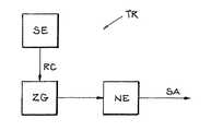
- FIG. 1is a block diagram of a transponder having a random number generator—that is operated in an operating mode for generating random numbers or in a counter operating mode—, a control logic unit, and a zero detection unit;
- FIG. 2is a timing diagram of control signals of the units from FIG. 1 during a selection process.
- FIG. 3is a state diagram of the transponder from FIG. 1 during the selection process shown in FIG. 2 .
- FIG. 1shows a block diagram of a backscatter-based, passive transponder TR with a control logic unit SE, a random number generator ZG that operates either in an operating mode for generating random numbers or in a counter operating mode as a function of a signal RC provided by the control logic unit SE, and a zero detection unit NE that provides a signal SA, which signal enables the transmission of a transponder-specific identification to a base station.
- the random number generator ZGis configured as a linear feedback shift register that is operated with a clock provided in the transponder TR.
- the clock provided in the transponder TRexhibits a certain dispersion between different transponders, by which means different values arise in the shift registers of the transponders in question after a certain operating period.
- the random number generator ZGis configured as a conventional counter, for example as a ripple counter.
- the zero detection unit NEis coupled to the random number generator ZG and monitors the count state of the random number generator ZG when the latter is in the counter operating mode. If the count state of the random number generator ZG is zero, the signal SA becomes active, thus activating the transmission of the transponder-specific identification to the base station.
- FIG. 2shows a timing diagram of control signals of the units shown in FIG. 1 during a selection process by a base station BS.
- the selection method or selection processin this example, is based on a slotted ALOHA selection method or on a dynamic slotted ALOHA selection method.
- the base stationinitiates the selection process by transmitting a selection command AK.
- the transponder TRreceives the selection command AK.
- the control logic unit SEthen activates the signal RC by a level transition from low to high.
- the random number generator ZGis switched over from the operating mode for generating random numbers to the counter operating mode by clocking of the linear feedback shift register.
- a count state ZS of the random number generatoris decremented when the base station transmits the start of a time slot.
- the initial count state ZShere is the random number contained in the shift register prior to the switchover into the counter operating mode. In the example embodiment shown, the initial count state ZS is 3.
- the base stationnow transmits a command NS, which indicates the start of a time slot.
- the count state ZS of the random number generator ZGis reduced by one, to 2.
- the zero detection unit NEchecks whether the count state ZS is zero. Since this is not yet the case, the signal SA remains at a low level.
- the base station BSnow transmits two additional commands NS, with the count state ZS again being reduced by one in each case.
- the count state ZSis zero.
- the zero detection unit NEdetects this, and activates the signal SA by a level transition from low to high.
- the transponder TRtransmits a transponder-specific identification ID to the base station BS.
- the base station BSreceives the transponder-specific identification ID and sends an acknowledgement signal QS to the transponder TR.
- the transponder TRis now selected in the current time slot, which is indicated by a signal SEL.
- the base station BScan then, for example, perform write and/or read operations (not shown) on the transponder TR.
- the control logic unit SEdeactivates the signal RC through a level transition from high to low.
- the random number generator ZGis again switched over to the operating mode for generating random numbers by clocking of the linear feedback shift register, with an initial value X being assigned to the shift register. This switchover could also be omitted in the case shown, since the base station BS transmits the acknowledgement signal QS.
- the base station BStransmits an additional command NS, indicating a new time slot in which other transponders (not shown) can be selected.
- the transponder shownthen withdraws from the current selection process.
- FIG. 3shows a state diagram of the transponder from FIG. 1 during the selection process shown in FIG. 2 .
- the transponder TRis in a base state Z 1 .
- the random number generator ZGcontinuously generates random numbers.
- the transponder TRWhen the transponder TR receives the command AK sent by the base station BS, it switches to a state Z 2 . In the state Z 2 , the random number generator ZG is switched over to the counter operating mode. The initial count state ZS now is the random number contained in the shift register prior to the switchover to the counter operating mode. The transponder now waits to receive a command NS.
- the transponder TRWhen the transponder TR receives the command NS sent by the base station BS, it switches to a state Z 3 and decrements the count state ZS. In the state Z 3 , the count state ZS is decremented by one each time a command NS is received from the base station.
- the transponder TRswitches to a state Z 4 , in which it transmits its transponder-specific identification ID to the base station BS.
- the random number generator ZGis then again switched over into the operating mode for random number generation.
- the transpondernow waits to receive the acknowledgement command QS from the base station BS.
- the transponder TRWhen the transponder TR receives the acknowledgement command QS sent by the base station BS, it switches to a state Z 5 during which it is selected. The base station BS can then, for example, perform write and/or read operations (not shown) on the transponder TR.
- the transponder TRWhen the transponder TR receives another command NS sent by the base station BS, it switches back to the state Z 1 , which is to say it withdraws from the current selection process and waits for a new selection command AK.
- the generated random numbercan be stored after the command AK is received, with the count state of the random number generator now functioning as a counter then being set to an initial value, in particular zero. As in the illustrated example embodiment, the count state is also incremented with each command NS.
- the transpondertransmits its transponder-specific identification to the base station when the count state is equal to the stored value of the random number.
- the embodiment shownreduces the number of components needed for a slotted selection process, making it possible to reduce the chip area required.
- the available random number spaceis better utilized as a result of the early switchover to renewed random number generation. This permits an additional selection process immediately thereafter, if such is necessary.
Landscapes
- Engineering & Computer Science (AREA)
- Physics & Mathematics (AREA)
- General Physics & Mathematics (AREA)
- Theoretical Computer Science (AREA)
- Toxicology (AREA)
- Health & Medical Sciences (AREA)
- Computer Vision & Pattern Recognition (AREA)
- Computer Networks & Wireless Communication (AREA)
- Artificial Intelligence (AREA)
- Electromagnetism (AREA)
- General Health & Medical Sciences (AREA)
- Computer Hardware Design (AREA)
- Microelectronics & Electronic Packaging (AREA)
- Mobile Radio Communication Systems (AREA)
- Time-Division Multiplex Systems (AREA)
- Radar Systems Or Details Thereof (AREA)
Abstract
Description
Claims (20)
Priority Applications (1)
| Application Number | Priority Date | Filing Date | Title |
|---|---|---|---|
| US14/145,139US9224020B2 (en) | 2004-08-27 | 2013-12-31 | Method, transponder, and circuit for selecting one or more transponders |
Applications Claiming Priority (6)
| Application Number | Priority Date | Filing Date | Title |
|---|---|---|---|
| DE102004041437 | 2004-08-27 | ||
| DE102004041437ADE102004041437B3 (en) | 2004-08-27 | 2004-08-27 | Method for selecting one or more transponders |
| DE102004041437.8-31 | 2004-08-27 | ||
| US11/210,896US20060044114A1 (en) | 2004-08-27 | 2005-08-25 | Method for selecting one or more transponders |
| US13/051,797US8638195B2 (en) | 2004-08-27 | 2011-03-18 | Method, transponder, and circuit for selecting one or more transponders |
| US14/145,139US9224020B2 (en) | 2004-08-27 | 2013-12-31 | Method, transponder, and circuit for selecting one or more transponders |
Related Parent Applications (1)
| Application Number | Title | Priority Date | Filing Date |
|---|---|---|---|
| US13/051,797ContinuationUS8638195B2 (en) | 2004-08-27 | 2011-03-18 | Method, transponder, and circuit for selecting one or more transponders |
Publications (2)
| Publication Number | Publication Date |
|---|---|
| US20140111309A1 US20140111309A1 (en) | 2014-04-24 |
| US9224020B2true US9224020B2 (en) | 2015-12-29 |
Family
ID=35385456
Family Applications (3)
| Application Number | Title | Priority Date | Filing Date |
|---|---|---|---|
| US11/210,896AbandonedUS20060044114A1 (en) | 2004-08-27 | 2005-08-25 | Method for selecting one or more transponders |
| US13/051,797Expired - LifetimeUS8638195B2 (en) | 2004-08-27 | 2011-03-18 | Method, transponder, and circuit for selecting one or more transponders |
| US14/145,139Expired - LifetimeUS9224020B2 (en) | 2004-08-27 | 2013-12-31 | Method, transponder, and circuit for selecting one or more transponders |
Family Applications Before (2)
| Application Number | Title | Priority Date | Filing Date |
|---|---|---|---|
| US11/210,896AbandonedUS20060044114A1 (en) | 2004-08-27 | 2005-08-25 | Method for selecting one or more transponders |
| US13/051,797Expired - LifetimeUS8638195B2 (en) | 2004-08-27 | 2011-03-18 | Method, transponder, and circuit for selecting one or more transponders |
Country Status (5)
| Country | Link |
|---|---|
| US (3) | US20060044114A1 (en) |
| EP (1) | EP1630715B1 (en) |
| JP (1) | JP2006067600A (en) |
| CN (1) | CN1741400B (en) |
| DE (2) | DE102004041437B3 (en) |
Families Citing this family (13)
| Publication number | Priority date | Publication date | Assignee | Title |
|---|---|---|---|---|
| KR100625675B1 (en)* | 2005-09-30 | 2006-09-18 | 에스케이 텔레콤주식회사 | Multiple Tag Identification Method Using Adaptive Binary Tree Segmentation in RFID System and RFID System for the Same |
| US8299900B2 (en)* | 2006-09-27 | 2012-10-30 | Alcatel Lucent | Anonymous tracking using a set of wireless devices |
| US7999675B2 (en)* | 2007-02-21 | 2011-08-16 | Impinj, Inc. | RFID tags replying using changed reply timing |
| US8446258B2 (en)* | 2007-02-21 | 2013-05-21 | Impinj, Inc. | Causing RFID tag to change how many remaining commands it will comply with |
| CN101441699B (en)* | 2007-11-20 | 2011-08-10 | 中兴通讯股份有限公司 | Multiple-label anti-collision method for radio frequency recognition |
| DE102009005352A1 (en) | 2009-01-16 | 2010-07-22 | Oliver Bartels | Radio device/network device, has two different slots or transmission facilities or frequencies with optical colors, used for message, where message is redundantly transferred to slots or transmission facilities or frequencies or colors |
| US9081996B2 (en)* | 2009-05-21 | 2015-07-14 | Alcatel Lucent | Identifying RFID categories |
| EP2509027B1 (en)* | 2011-04-04 | 2019-02-06 | Nxp B.V. | Method for handling collision in an identification system |
| KR101307491B1 (en)* | 2011-10-18 | 2013-09-11 | 성균관대학교산학협력단 | Anti-collision system and method with moving tags in rfid systems |
| US11163050B2 (en) | 2013-08-09 | 2021-11-02 | The Board Of Trustees Of The Leland Stanford Junior University | Backscatter estimation using progressive self interference cancellation |
| CN104918361B (en)* | 2015-05-08 | 2017-11-21 | 中山易能智达电子有限公司 | Scanning recognition method between controller and actuator in wireless lighting control system |
| DE102016113302A1 (en)* | 2016-07-19 | 2018-01-25 | Sick Ag | RFID device and method for communicating with at least one RFID transponder |
| JP2020509618A (en)* | 2016-10-25 | 2020-03-26 | ザ ボード オブ トラスティーズ オブ ザ レランド スタンフォード ジュニア ユニバーシティー | Backscatter ambient ISM band signal |
Citations (13)
| Publication number | Priority date | Publication date | Assignee | Title |
|---|---|---|---|---|
| US4471345A (en) | 1982-03-05 | 1984-09-11 | Sensormatic Electronics Corporation | Randomized tag to portal communication system |
| US5124699A (en) | 1989-06-30 | 1992-06-23 | N.V. Netherlandsche Apparatenfabriek Nedap | Electromagnetic identification system for identifying a plurality of coded responders simultaneously present in an interrogation field |
| US5550547A (en) | 1994-09-12 | 1996-08-27 | International Business Machines Corporation | Multiple item radio frequency tag identification protocol |
| US5875465A (en) | 1996-04-03 | 1999-02-23 | Arm Limited | Cache control circuit having a pseudo random address generator |
| US6154136A (en) | 1998-02-26 | 2000-11-28 | Van Eeden; Hendrik Lodewyk | Free running RF identification system with increasing average inter transmission intervals |
| US20010014090A1 (en) | 1998-02-19 | 2001-08-16 | Wood Clifton W. | Method of addressing messages and communications system |
| US6499656B1 (en) | 1998-03-04 | 2002-12-31 | Trolley Scan (Proprietary) Limited | Identification of objects by a reader |
| US6538563B1 (en) | 1998-03-18 | 2003-03-25 | National University Of Singapore | RF transponder identification system and protocol |
| WO2003040998A1 (en) | 2001-11-07 | 2003-05-15 | Supersensor (Pty) Limited | Method and system for periodically sampling a plurality of transponders |
| US20030179078A1 (en) | 2002-03-25 | 2003-09-25 | Holtek Semiconductor Inc. | Radio frequency tag circuit and method for reading multiple tags |
| WO2003107256A1 (en) | 2002-06-14 | 2003-12-24 | Btg International Limited | Electronic identification system |
| US20040012486A1 (en)* | 2002-06-04 | 2004-01-22 | Stmicroelectronics Sa | Anti-collision method for contactless electronic module |
| US20040160310A1 (en) | 2003-02-14 | 2004-08-19 | Mao-Song Chen | Radio frequency identification device |
Family Cites Families (3)
| Publication number | Priority date | Publication date | Assignee | Title |
|---|---|---|---|---|
| JPH02272822A (en)* | 1989-04-13 | 1990-11-07 | Fujitsu Ltd | Register with counter function and shift register function |
| JP4116273B2 (en)* | 2001-09-10 | 2008-07-09 | 株式会社東芝 | Wireless card having random number generator, semiconductor device for the wireless card, and wireless card system using the wireless card |
| JP2004054394A (en)* | 2002-07-17 | 2004-02-19 | Toshiba Corp | Wireless information processing system, wireless information recording medium, wireless information processing apparatus, and communication method of wireless information processing system |
- 2004
- 2004-08-27DEDE102004041437Apatent/DE102004041437B3/ennot_activeExpired - Fee Related
- 2005
- 2005-08-23DEDE502005001603Tpatent/DE502005001603D1/ennot_activeExpired - Lifetime
- 2005-08-23EPEP05018246Apatent/EP1630715B1/ennot_activeExpired - Lifetime
- 2005-08-25USUS11/210,896patent/US20060044114A1/ennot_activeAbandoned
- 2005-08-26JPJP2005246748Apatent/JP2006067600A/enactivePending
- 2005-08-29CNCN200510099408XApatent/CN1741400B/ennot_activeExpired - Fee Related
- 2011
- 2011-03-18USUS13/051,797patent/US8638195B2/ennot_activeExpired - Lifetime
- 2013
- 2013-12-31USUS14/145,139patent/US9224020B2/ennot_activeExpired - Lifetime
Patent Citations (13)
| Publication number | Priority date | Publication date | Assignee | Title |
|---|---|---|---|---|
| US4471345A (en) | 1982-03-05 | 1984-09-11 | Sensormatic Electronics Corporation | Randomized tag to portal communication system |
| US5124699A (en) | 1989-06-30 | 1992-06-23 | N.V. Netherlandsche Apparatenfabriek Nedap | Electromagnetic identification system for identifying a plurality of coded responders simultaneously present in an interrogation field |
| US5550547A (en) | 1994-09-12 | 1996-08-27 | International Business Machines Corporation | Multiple item radio frequency tag identification protocol |
| US5875465A (en) | 1996-04-03 | 1999-02-23 | Arm Limited | Cache control circuit having a pseudo random address generator |
| US20010014090A1 (en) | 1998-02-19 | 2001-08-16 | Wood Clifton W. | Method of addressing messages and communications system |
| US6154136A (en) | 1998-02-26 | 2000-11-28 | Van Eeden; Hendrik Lodewyk | Free running RF identification system with increasing average inter transmission intervals |
| US6499656B1 (en) | 1998-03-04 | 2002-12-31 | Trolley Scan (Proprietary) Limited | Identification of objects by a reader |
| US6538563B1 (en) | 1998-03-18 | 2003-03-25 | National University Of Singapore | RF transponder identification system and protocol |
| WO2003040998A1 (en) | 2001-11-07 | 2003-05-15 | Supersensor (Pty) Limited | Method and system for periodically sampling a plurality of transponders |
| US20030179078A1 (en) | 2002-03-25 | 2003-09-25 | Holtek Semiconductor Inc. | Radio frequency tag circuit and method for reading multiple tags |
| US20040012486A1 (en)* | 2002-06-04 | 2004-01-22 | Stmicroelectronics Sa | Anti-collision method for contactless electronic module |
| WO2003107256A1 (en) | 2002-06-14 | 2003-12-24 | Btg International Limited | Electronic identification system |
| US20040160310A1 (en) | 2003-02-14 | 2004-08-19 | Mao-Song Chen | Radio frequency identification device |
Non-Patent Citations (1)
| Title |
|---|
| Finkenzeller, Klaus RFID-Handbuch: 3rd edition, Carl Hanser Verlag Munchen, Wien, pp. 203-224, 2002. |
Also Published As
| Publication number | Publication date |
|---|---|
| EP1630715B1 (en) | 2007-10-03 |
| CN1741400A (en) | 2006-03-01 |
| CN1741400B (en) | 2010-06-23 |
| US20110163853A1 (en) | 2011-07-07 |
| DE102004041437B3 (en) | 2006-03-09 |
| EP1630715A1 (en) | 2006-03-01 |
| US20140111309A1 (en) | 2014-04-24 |
| DE502005001603D1 (en) | 2007-11-15 |
| US8638195B2 (en) | 2014-01-28 |
| JP2006067600A (en) | 2006-03-09 |
| US20060044114A1 (en) | 2006-03-02 |
Similar Documents
| Publication | Publication Date | Title |
|---|---|---|
| US9224020B2 (en) | Method, transponder, and circuit for selecting one or more transponders | |
| Vogt | Efficient object identification with passive RFID tags | |
| US6952157B1 (en) | System and method for concurrently addressing multiple radio frequency identification tags from a single reader | |
| EP0898815B1 (en) | Transponder communications device | |
| KR101048612B1 (en) | RFID tag recognition method to prevent RFID tag collision, RFID reader and RFID tag using same | |
| US6456191B1 (en) | Tag system with anti-collision features | |
| US7312692B2 (en) | Method for selecting one or several transponders | |
| US8477017B2 (en) | Method, system, and integrated circuit for communication in RFID or remote sensor systems | |
| US20070075838A1 (en) | Method and apparatus for avoiding radio frequency identification (RFID) tag response collisions | |
| US20060232383A1 (en) | RFID tag and RFID reader for anti-collision and operating method thereof | |
| WO2008069891A2 (en) | Rfid communication systems and methods, and rfid readers and systems | |
| JP2006302283A (en) | RFID reader and RFID tag using bit synchronization signal, and tag recognition system and method | |
| JP2007533016A (en) | Method for selecting one or more transponders | |
| US20030116626A1 (en) | IC card reader/writer, identification method and program | |
| US7152799B2 (en) | Contactless IC card | |
| KR19990067371A (en) | Transmitter Identification System and Method for Improved Multiple Data Transmission Detection | |
| EP0910899B1 (en) | Transponder communication device | |
| US20050231327A1 (en) | Method for selecting one or more transponders | |
| KR100926130B1 (en) | Aloha-based Tag Recognition Method in RF ID System | |
| RU2388157C2 (en) | Method of preventing conflicts in radio frequency identification technology | |
| US6961829B2 (en) | Data carrier comprising memory means for storing information significant for intermediate operating states | |
| EP1798660A2 (en) | Method of reading a plurality of non-contact data carriers, including an anti-collision scheme | |
| US20050231326A1 (en) | Maintenance of an anticollision channel in an electronic identification system | |
| KR100747758B1 (en) | Apparatus and Method for Preventing Data Collision in Wireless Recognition System | |
| Alma'aitah et al. | Modulation silencing: Novel RFID anti-collision resolution for passive tags |
Legal Events
| Date | Code | Title | Description |
|---|---|---|---|
| AS | Assignment | Owner name:ATMEL CORPORATION, CALIFORNIA Free format text:ASSIGNMENT OF ASSIGNORS INTEREST;ASSIGNOR:ATMEL AUTOMOTIVE GMBH;REEL/FRAME:031863/0162 Effective date:20110228 Owner name:ATMEL AUTOMOTIVE GMBH, GERMANY Free format text:ASSIGNMENT OF ASSIGNORS INTEREST;ASSIGNOR:ATMEL GERMANY GMBH & CO KG;REEL/FRAME:031863/0227 Effective date:20081205 Owner name:ATMEL GERMANY GMBH, GERMANY Free format text:ASSIGNMENT OF ASSIGNORS INTEREST;ASSIGNOR:FRIEDRICH, ULRICH;REEL/FRAME:031863/0262 Effective date:20050825 | |
| AS | Assignment | Owner name:ATMEL GERMANY GMBH, GERMANY Free format text:ASSIGNMENT OF ASSIGNORS INTEREST;ASSIGNOR:PANGELS, MICHAEL;REEL/FRAME:032236/0873 Effective date:20050825 | |
| AS | Assignment | Owner name:MORGAN STANLEY SENIOR FUNDING, INC., NEW YORK Free format text:PATENT SECURITY AGREEMENT;ASSIGNOR:ATMEL CORPORATION;REEL/FRAME:032908/0485 Effective date:20131206 | |
| STCF | Information on status: patent grant | Free format text:PATENTED CASE | |
| AS | Assignment | Owner name:ATMEL CORPORATION, CALIFORNIA Free format text:TERMINATION AND RELEASE OF SECURITY INTEREST IN PATENT COLLATERAL;ASSIGNOR:MORGAN STANLEY SENIOR FUNDING, INC.;REEL/FRAME:038375/0490 Effective date:20160404 | |
| AS | Assignment | Owner name:JPMORGAN CHASE BANK, N.A., AS ADMINISTRATIVE AGENT, ILLINOIS Free format text:SECURITY INTEREST;ASSIGNOR:ATMEL CORPORATION;REEL/FRAME:041715/0747 Effective date:20170208 Owner name:JPMORGAN CHASE BANK, N.A., AS ADMINISTRATIVE AGENT Free format text:SECURITY INTEREST;ASSIGNOR:ATMEL CORPORATION;REEL/FRAME:041715/0747 Effective date:20170208 | |
| AS | Assignment | Owner name:JPMORGAN CHASE BANK, N.A., AS ADMINISTRATIVE AGENT, ILLINOIS Free format text:SECURITY INTEREST;ASSIGNORS:MICROCHIP TECHNOLOGY INCORPORATED;SILICON STORAGE TECHNOLOGY, INC.;ATMEL CORPORATION;AND OTHERS;REEL/FRAME:046426/0001 Effective date:20180529 Owner name:JPMORGAN CHASE BANK, N.A., AS ADMINISTRATIVE AGENT Free format text:SECURITY INTEREST;ASSIGNORS:MICROCHIP TECHNOLOGY INCORPORATED;SILICON STORAGE TECHNOLOGY, INC.;ATMEL CORPORATION;AND OTHERS;REEL/FRAME:046426/0001 Effective date:20180529 | |
| AS | Assignment | Owner name:WELLS FARGO BANK, NATIONAL ASSOCIATION, AS NOTES COLLATERAL AGENT, CALIFORNIA Free format text:SECURITY INTEREST;ASSIGNORS:MICROCHIP TECHNOLOGY INCORPORATED;SILICON STORAGE TECHNOLOGY, INC.;ATMEL CORPORATION;AND OTHERS;REEL/FRAME:047103/0206 Effective date:20180914 Owner name:WELLS FARGO BANK, NATIONAL ASSOCIATION, AS NOTES C Free format text:SECURITY INTEREST;ASSIGNORS:MICROCHIP TECHNOLOGY INCORPORATED;SILICON STORAGE TECHNOLOGY, INC.;ATMEL CORPORATION;AND OTHERS;REEL/FRAME:047103/0206 Effective date:20180914 | |
| MAFP | Maintenance fee payment | Free format text:PAYMENT OF MAINTENANCE FEE, 4TH YEAR, LARGE ENTITY (ORIGINAL EVENT CODE: M1551); ENTITY STATUS OF PATENT OWNER: LARGE ENTITY Year of fee payment:4 | |
| AS | Assignment | Owner name:JPMORGAN CHASE BANK, N.A., AS ADMINISTRATIVE AGENT, DELAWARE Free format text:SECURITY INTEREST;ASSIGNORS:MICROCHIP TECHNOLOGY INC.;SILICON STORAGE TECHNOLOGY, INC.;ATMEL CORPORATION;AND OTHERS;REEL/FRAME:053311/0305 Effective date:20200327 | |
| AS | Assignment | Owner name:SILICON STORAGE TECHNOLOGY, INC., ARIZONA Free format text:RELEASE BY SECURED PARTY;ASSIGNOR:JPMORGAN CHASE BANK, N.A, AS ADMINISTRATIVE AGENT;REEL/FRAME:053466/0011 Effective date:20200529 Owner name:MICROSEMI STORAGE SOLUTIONS, INC., ARIZONA Free format text:RELEASE BY SECURED PARTY;ASSIGNOR:JPMORGAN CHASE BANK, N.A, AS ADMINISTRATIVE AGENT;REEL/FRAME:053466/0011 Effective date:20200529 Owner name:MICROCHIP TECHNOLOGY INC., ARIZONA Free format text:RELEASE BY SECURED PARTY;ASSIGNOR:JPMORGAN CHASE BANK, N.A, AS ADMINISTRATIVE AGENT;REEL/FRAME:053466/0011 Effective date:20200529 Owner name:ATMEL CORPORATION, ARIZONA Free format text:RELEASE BY SECURED PARTY;ASSIGNOR:JPMORGAN CHASE BANK, N.A, AS ADMINISTRATIVE AGENT;REEL/FRAME:053466/0011 Effective date:20200529 Owner name:MICROSEMI CORPORATION, CALIFORNIA Free format text:RELEASE BY SECURED PARTY;ASSIGNOR:JPMORGAN CHASE BANK, N.A, AS ADMINISTRATIVE AGENT;REEL/FRAME:053466/0011 Effective date:20200529 | |
| AS | Assignment | Owner name:WELLS FARGO BANK, NATIONAL ASSOCIATION, MINNESOTA Free format text:SECURITY INTEREST;ASSIGNORS:MICROCHIP TECHNOLOGY INC.;SILICON STORAGE TECHNOLOGY, INC.;ATMEL CORPORATION;AND OTHERS;REEL/FRAME:053468/0705 Effective date:20200529 | |
| AS | Assignment | Owner name:WELLS FARGO BANK, NATIONAL ASSOCIATION, AS COLLATERAL AGENT, MINNESOTA Free format text:SECURITY INTEREST;ASSIGNORS:MICROCHIP TECHNOLOGY INCORPORATED;SILICON STORAGE TECHNOLOGY, INC.;ATMEL CORPORATION;AND OTHERS;REEL/FRAME:055671/0612 Effective date:20201217 | |
| AS | Assignment | Owner name:WELLS FARGO BANK, NATIONAL ASSOCIATION, AS NOTES COLLATERAL AGENT, MINNESOTA Free format text:SECURITY INTEREST;ASSIGNORS:MICROCHIP TECHNOLOGY INCORPORATED;SILICON STORAGE TECHNOLOGY, INC.;ATMEL CORPORATION;AND OTHERS;REEL/FRAME:057935/0474 Effective date:20210528 | |
| AS | Assignment | Owner name:MICROSEMI STORAGE SOLUTIONS, INC., ARIZONA Free format text:RELEASE BY SECURED PARTY;ASSIGNOR:JPMORGAN CHASE BANK, N.A., AS ADMINISTRATIVE AGENT;REEL/FRAME:059333/0222 Effective date:20220218 Owner name:MICROSEMI CORPORATION, ARIZONA Free format text:RELEASE BY SECURED PARTY;ASSIGNOR:JPMORGAN CHASE BANK, N.A., AS ADMINISTRATIVE AGENT;REEL/FRAME:059333/0222 Effective date:20220218 Owner name:ATMEL CORPORATION, ARIZONA Free format text:RELEASE BY SECURED PARTY;ASSIGNOR:JPMORGAN CHASE BANK, N.A., AS ADMINISTRATIVE AGENT;REEL/FRAME:059333/0222 Effective date:20220218 Owner name:SILICON STORAGE TECHNOLOGY, INC., ARIZONA Free format text:RELEASE BY SECURED PARTY;ASSIGNOR:JPMORGAN CHASE BANK, N.A., AS ADMINISTRATIVE AGENT;REEL/FRAME:059333/0222 Effective date:20220218 Owner name:MICROCHIP TECHNOLOGY INCORPORATED, ARIZONA Free format text:RELEASE BY SECURED PARTY;ASSIGNOR:JPMORGAN CHASE BANK, N.A., AS ADMINISTRATIVE AGENT;REEL/FRAME:059333/0222 Effective date:20220218 | |
| AS | Assignment | Owner name:ATMEL CORPORATION, ARIZONA Free format text:RELEASE BY SECURED PARTY;ASSIGNOR:JPMORGAN CHASE BANK, N.A., AS ADMINISTRATIVE AGENT;REEL/FRAME:059262/0105 Effective date:20220218 | |
| AS | Assignment | Owner name:MICROSEMI STORAGE SOLUTIONS, INC., ARIZONA Free format text:RELEASE BY SECURED PARTY;ASSIGNOR:WELLS FARGO BANK, NATIONAL ASSOCIATION, AS NOTES COLLATERAL AGENT;REEL/FRAME:059358/0001 Effective date:20220228 Owner name:MICROSEMI CORPORATION, ARIZONA Free format text:RELEASE BY SECURED PARTY;ASSIGNOR:WELLS FARGO BANK, NATIONAL ASSOCIATION, AS NOTES COLLATERAL AGENT;REEL/FRAME:059358/0001 Effective date:20220228 Owner name:ATMEL CORPORATION, ARIZONA Free format text:RELEASE BY SECURED PARTY;ASSIGNOR:WELLS FARGO BANK, NATIONAL ASSOCIATION, AS NOTES COLLATERAL AGENT;REEL/FRAME:059358/0001 Effective date:20220228 Owner name:SILICON STORAGE TECHNOLOGY, INC., ARIZONA Free format text:RELEASE BY SECURED PARTY;ASSIGNOR:WELLS FARGO BANK, NATIONAL ASSOCIATION, AS NOTES COLLATERAL AGENT;REEL/FRAME:059358/0001 Effective date:20220228 Owner name:MICROCHIP TECHNOLOGY INCORPORATED, ARIZONA Free format text:RELEASE BY SECURED PARTY;ASSIGNOR:WELLS FARGO BANK, NATIONAL ASSOCIATION, AS NOTES COLLATERAL AGENT;REEL/FRAME:059358/0001 Effective date:20220228 | |
| AS | Assignment | Owner name:MICROSEMI STORAGE SOLUTIONS, INC., ARIZONA Free format text:RELEASE BY SECURED PARTY;ASSIGNOR:WELLS FARGO BANK, NATIONAL ASSOCIATION, AS NOTES COLLATERAL AGENT;REEL/FRAME:059863/0400 Effective date:20220228 Owner name:MICROSEMI CORPORATION, ARIZONA Free format text:RELEASE BY SECURED PARTY;ASSIGNOR:WELLS FARGO BANK, NATIONAL ASSOCIATION, AS NOTES COLLATERAL AGENT;REEL/FRAME:059863/0400 Effective date:20220228 Owner name:ATMEL CORPORATION, ARIZONA Free format text:RELEASE BY SECURED PARTY;ASSIGNOR:WELLS FARGO BANK, NATIONAL ASSOCIATION, AS NOTES COLLATERAL AGENT;REEL/FRAME:059863/0400 Effective date:20220228 Owner name:SILICON STORAGE TECHNOLOGY, INC., ARIZONA Free format text:RELEASE BY SECURED PARTY;ASSIGNOR:WELLS FARGO BANK, NATIONAL ASSOCIATION, AS NOTES COLLATERAL AGENT;REEL/FRAME:059863/0400 Effective date:20220228 Owner name:MICROCHIP TECHNOLOGY INCORPORATED, ARIZONA Free format text:RELEASE BY SECURED PARTY;ASSIGNOR:WELLS FARGO BANK, NATIONAL ASSOCIATION, AS NOTES COLLATERAL AGENT;REEL/FRAME:059863/0400 Effective date:20220228 | |
| AS | Assignment | Owner name:MICROSEMI STORAGE SOLUTIONS, INC., ARIZONA Free format text:RELEASE BY SECURED PARTY;ASSIGNOR:WELLS FARGO BANK, NATIONAL ASSOCIATION, AS NOTES COLLATERAL AGENT;REEL/FRAME:059363/0001 Effective date:20220228 Owner name:MICROSEMI CORPORATION, ARIZONA Free format text:RELEASE BY SECURED PARTY;ASSIGNOR:WELLS FARGO BANK, NATIONAL ASSOCIATION, AS NOTES COLLATERAL AGENT;REEL/FRAME:059363/0001 Effective date:20220228 Owner name:ATMEL CORPORATION, ARIZONA Free format text:RELEASE BY SECURED PARTY;ASSIGNOR:WELLS FARGO BANK, NATIONAL ASSOCIATION, AS NOTES COLLATERAL AGENT;REEL/FRAME:059363/0001 Effective date:20220228 Owner name:SILICON STORAGE TECHNOLOGY, INC., ARIZONA Free format text:RELEASE BY SECURED PARTY;ASSIGNOR:WELLS FARGO BANK, NATIONAL ASSOCIATION, AS NOTES COLLATERAL AGENT;REEL/FRAME:059363/0001 Effective date:20220228 Owner name:MICROCHIP TECHNOLOGY INCORPORATED, ARIZONA Free format text:RELEASE BY SECURED PARTY;ASSIGNOR:WELLS FARGO BANK, NATIONAL ASSOCIATION, AS NOTES COLLATERAL AGENT;REEL/FRAME:059363/0001 Effective date:20220228 | |
| AS | Assignment | Owner name:MICROSEMI STORAGE SOLUTIONS, INC., ARIZONA Free format text:RELEASE BY SECURED PARTY;ASSIGNOR:WELLS FARGO BANK, NATIONAL ASSOCIATION, AS NOTES COLLATERAL AGENT;REEL/FRAME:060894/0437 Effective date:20220228 Owner name:MICROSEMI CORPORATION, ARIZONA Free format text:RELEASE BY SECURED PARTY;ASSIGNOR:WELLS FARGO BANK, NATIONAL ASSOCIATION, AS NOTES COLLATERAL AGENT;REEL/FRAME:060894/0437 Effective date:20220228 Owner name:ATMEL CORPORATION, ARIZONA Free format text:RELEASE BY SECURED PARTY;ASSIGNOR:WELLS FARGO BANK, NATIONAL ASSOCIATION, AS NOTES COLLATERAL AGENT;REEL/FRAME:060894/0437 Effective date:20220228 Owner name:SILICON STORAGE TECHNOLOGY, INC., ARIZONA Free format text:RELEASE BY SECURED PARTY;ASSIGNOR:WELLS FARGO BANK, NATIONAL ASSOCIATION, AS NOTES COLLATERAL AGENT;REEL/FRAME:060894/0437 Effective date:20220228 Owner name:MICROCHIP TECHNOLOGY INCORPORATED, ARIZONA Free format text:RELEASE BY SECURED PARTY;ASSIGNOR:WELLS FARGO BANK, NATIONAL ASSOCIATION, AS NOTES COLLATERAL AGENT;REEL/FRAME:060894/0437 Effective date:20220228 | |
| MAFP | Maintenance fee payment | Free format text:PAYMENT OF MAINTENANCE FEE, 8TH YEAR, LARGE ENTITY (ORIGINAL EVENT CODE: M1552); ENTITY STATUS OF PATENT OWNER: LARGE ENTITY Year of fee payment:8 |