US9221496B2 - Suspension module having a skidplate - Google Patents
Suspension module having a skidplateDownload PDFInfo
- Publication number
- US9221496B2 US9221496B2US13/915,685US201313915685AUS9221496B2US 9221496 B2US9221496 B2US 9221496B2US 201313915685 AUS201313915685 AUS 201313915685AUS 9221496 B2US9221496 B2US 9221496B2
- Authority
- US
- United States
- Prior art keywords
- subframe
- skid plate
- mounting
- notch
- suspension module
- Prior art date
- Legal status (The legal status is an assumption and is not a legal conclusion. Google has not performed a legal analysis and makes no representation as to the accuracy of the status listed.)
- Active, expires
Links
- 239000000725suspensionSubstances0.000titleclaimsabstractdescription44
- 239000006096absorbing agentSubstances0.000description5
- 230000008878couplingEffects0.000description5
- 238000010168coupling processMethods0.000description5
- 238000005859coupling reactionMethods0.000description5
- 230000035939shockEffects0.000description5
- 230000000712assemblyEffects0.000description3
- 238000000429assemblyMethods0.000description3
- 230000005540biological transmissionEffects0.000description1
- 230000007547defectEffects0.000description1
- 238000003466weldingMethods0.000description1
Images


Classifications
- B—PERFORMING OPERATIONS; TRANSPORTING
- B62—LAND VEHICLES FOR TRAVELLING OTHERWISE THAN ON RAILS
- B62D—MOTOR VEHICLES; TRAILERS
- B62D21/00—Understructures, i.e. chassis frame on which a vehicle body may be mounted
- B62D21/15—Understructures, i.e. chassis frame on which a vehicle body may be mounted having impact absorbing means, e.g. a frame designed to permanently or temporarily change shape or dimension upon impact with another body
- B62D21/152—Front or rear frames
- B62D21/155—Sub-frames or underguards
- B—PERFORMING OPERATIONS; TRANSPORTING
- B62—LAND VEHICLES FOR TRAVELLING OTHERWISE THAN ON RAILS
- B62D—MOTOR VEHICLES; TRAILERS
- B62D21/00—Understructures, i.e. chassis frame on which a vehicle body may be mounted
- B62D21/11—Understructures, i.e. chassis frame on which a vehicle body may be mounted with resilient means for suspension, e.g. of wheels or engine; sub-frames for mounting engine or suspensions
- B—PERFORMING OPERATIONS; TRANSPORTING
- B60—VEHICLES IN GENERAL
- B60K—ARRANGEMENT OR MOUNTING OF PROPULSION UNITS OR OF TRANSMISSIONS IN VEHICLES; ARRANGEMENT OR MOUNTING OF PLURAL DIVERSE PRIME-MOVERS IN VEHICLES; AUXILIARY DRIVES FOR VEHICLES; INSTRUMENTATION OR DASHBOARDS FOR VEHICLES; ARRANGEMENTS IN CONNECTION WITH COOLING, AIR INTAKE, GAS EXHAUST OR FUEL SUPPLY OF PROPULSION UNITS IN VEHICLES
- B60K17/00—Arrangement or mounting of transmissions in vehicles
- B60K17/04—Arrangement or mounting of transmissions in vehicles characterised by arrangement, location or kind of gearing
- B60K17/16—Arrangement or mounting of transmissions in vehicles characterised by arrangement, location or kind of gearing of differential gearing
- B60K17/165—Arrangement or mounting of transmissions in vehicles characterised by arrangement, location or kind of gearing of differential gearing provided between independent half axles
- B—PERFORMING OPERATIONS; TRANSPORTING
- B62—LAND VEHICLES FOR TRAVELLING OTHERWISE THAN ON RAILS
- B62D—MOTOR VEHICLES; TRAILERS
- B62D21/00—Understructures, i.e. chassis frame on which a vehicle body may be mounted
- B—PERFORMING OPERATIONS; TRANSPORTING
- B60—VEHICLES IN GENERAL
- B60G—VEHICLE SUSPENSION ARRANGEMENTS
- B60G2204/00—Indexing codes related to suspensions per se or to auxiliary parts
- B60G2204/10—Mounting of suspension elements
- B60G2204/15—Mounting of subframes
- B—PERFORMING OPERATIONS; TRANSPORTING
- B60—VEHICLES IN GENERAL
- B60G—VEHICLE SUSPENSION ARRANGEMENTS
- B60G2204/00—Indexing codes related to suspensions per se or to auxiliary parts
- B60G2204/10—Mounting of suspension elements
- B60G2204/19—Mounting of transmission differential
Definitions
- This applicationrelates to a suspension module for a vehicle having a skid plate.
- a suspension module for a vehiclemay include a subframe, upper and lower control arms, a skid plate, and a differential.
- the subframemay be configured to be mounted to the vehicle.
- the upper and lower control armsmay be pivotally mounted to the subframe.
- the skid platemay be mounted to the subframe proximate the lower control arm.
- the differentialmay be mounted to the skid plate.
- a suspension module for a vehiclemay include a subframe, a skid plate, and a differential.
- the subframemay be configured to be mounted to the vehicle.
- the subframemay have first and second arms disposed along a first side of the subframe and third and fourth arms disposed along a second side of the subframe.
- the skid platemay be mounted to the first, second, third, and fourth arms.
- the differentialmay be mounted to the skid plate and may be spaced apart from the subframe.
- a suspension module for a vehiclemay include a subframe, a skid plate, and a differential.
- the subframemay be configured to be mounted to the vehicle.
- the subframemay have a first arm that may have a mounting notch that extends from an end surface of the first arm.
- the skid platemay be received in the mounting notch such that an upper surface of the skid plate engages the first arm.
- the differentialmay be mounted to the upper surface of the skid plate and may be spaced apart from the subframe.
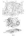
- FIG. 1is a perspective view of an exemplary suspension module.
- FIG. 2is an exploded view of a portion of the suspension module including a subframe, a differential, and a skid plate.
- FIG. 3is a top view of the portion of the suspension module shown in FIG. 2 .
- FIG. 4is a perspective view of the skid plate.
- the suspension module 10may be provided with a motor vehicle like a truck, bus, farm equipment, military transport or weaponry vehicle, or cargo loading equipment for land, air, or marine vessels.
- the suspension module 10may include an axle subassembly 20 , a suspension subsystem 22 , and a subframe assembly 24 .
- the axle subassembly 20may interconnect a plurality of wheel assemblies to the vehicle.
- the axle subassembly 20may include a differential 30 , at least one half shaft 32 , and a wheel hub assembly 34 .
- the differential 30may be configured to allow different wheels to rotate at different speeds.
- the differential 30may be part of or may be connected to a vehicle drivetrain that may provide torque to one or more wheels.
- a vehicle drivetrainmay include at least one power source, such as an engine and/or electric motor, and a power transfer unit, such as a transmission.
- the power sourcemay be connected to an input of the power transfer unit.
- An output of the power transfer unitmay be connected to an input 36 or input shaft of the differential 30 via a drive shaft.
- the drive shaftmay rotate the input 36 about an axis of rotation 38 , which is shown in FIG. 3 .
- a half shaft 32may interconnect the differential 30 to an associated wheel hub assembly 34 .
- two half shafts 32are provided that extend from opposite sides of the differential 30 .
- Each half shaft 32may extend along and may be configured to rotate about an axis.
- Each half shaft 32may be coupled to an output of the differential 30 at a first end and may be fixedly coupled to a corresponding wheel hub assembly 34 at a second end.
- the wheel hub assembly 34may facilitate coupling of a wheel to a half shaft 32 .
- the wheelmay be fixedly mounted on and may rotate with the wheel hub assembly 34 .
- a tiremay be disposed on the wheel that may engage a road or support surface.
- the differential 30may be fixedly mounted on the subframe assembly 24 .
- the differential 30may include a housing 40 that may engage or may be mounted to the subframe assembly 24 .
- the housing 40may be assembled from multiple individual components in one or more embodiments.
- the differential 30may or may not have an output shaft for transmitting torque to another differential, such as in a tandem axle configuration.
- the differential 30may have a front side 42 and a rear side 44 .
- the input 36may extend from the front side 42 .
- the rear side 44may be disposed opposite the front side 42 .
- the housing 40may include or may be coupled to a front mounting bracket 50 and a rear mounting bracket 52 .
- One or more front mounting brackets 50may interconnect the differential 30 to the subframe assembly 24 .
- two front mounting brackets 50are shown that are disposed on the front side 42 of the differential 30 and disposed proximate opposite sides of the input 36 or on opposite sides of the axis of rotation 38 or a plane that may extend through the axis of rotation 38 .
- the front mounting bracket 50may be integrally formed with the housing 40 or may be provided as a separate component that is not integrally formed with the housing 40 . In FIGS. 1-3 , the front mounting brackets 50 are provided separately from the housing 40 .
- the front mounting bracket 50may include a first end and a second end disposed opposite the first end.
- One or more differential mounting holes 54may be provided proximate the first end.
- the differential mounting holes 54may each receive a fastener 56 , such as a bolt, that may fixedly couple the front mounting bracket 50 to the housing 40 .
- the fastener 56may extend through a differential mounting hole 54 and into a corresponding threaded hole in the housing 40 .
- the front mounting bracket 50may also include a mounting pin hole 58 that may be disposed proximate the second end.
- the mounting pin hole 58may extend in the same direction or substantially parallel to a differential mounting hole 54 in one or more embodiments.
- the mounting pin hole 58may receive a mounting pin 60 .
- the mounting pin 60may extend through the mounting pin hole 58 such that first and second ends of the mounting pin 60 protrude from opposite sides of the front mounting bracket 50 , such as a first mounting bracket side 62 and a second mounting bracket side 64 .
- the first mounting bracket side 62may face away from the front side 42 of the differential 30 and the second mounting bracket side 64 is disposed opposite the first mounting bracket side 62 .
- the first and second ends of the mounting pin 60may each have a hole 66 that may receive a fastener 56 that may fixedly couple the mounting pin 60 to the subframe assembly 24 as will be discussed in more detail below.
- the rear mounting bracket 52may be integrally or non-integrally formed with the differential 30 .
- the rear mounting bracket 52may be integrally formed with the housing 40 or a housing component, such as a cover portion that may be assembled to a main portion of the housing 40 , and may be disposed on the rear side 44 of the differential 30 that may be disposed opposite the input 36 .
- the rear mounting bracket 52may include a mounting pin hole 70 disposed proximate a distal end of the rear mounting bracket 52 . As is best shown in FIG.
- the mounting pin hole 70may receive a mounting pin 60 that may extend through the mounting pin hole 70 such that first and second ends of the mounting pin 60 protrude from first and second sides 72 , 74 of the rear mounting bracket 52 .
- the first and second sides 72 , 74may be disposed opposite each other and face toward the wheel hub assemblies 34 .
- the mounting pin hole 70 in the rear mounting bracket 52may not be disposed parallel to the mounting pin hole 58 in the front mounting bracket 50 .
- the mounting pin hole 70is disposed substantially perpendicular to the mounting pin hole 58 .
- the first and second ends of the mounting pin 60may each have a hole 66 that may receive a fastener 56 that couples the mounting pin 60 to the subframe assembly 24 .
- the suspension subsystem 22may interconnect the axle subassembly 20 to the subframe assembly 24 and/or the vehicle chassis to dampen vibrations, to provide a desired level of ride quality, and/or to control vehicle ride height.
- the suspension subsystem 22may include an upper control arm 80 , a lower control arm 82 , a shock absorber 84 , and a coil spring 86 .
- the upper and lower control arms 80 , 82may couple the subframe assembly 24 to the wheel hub assembly 34 .
- the upper and lower control arms 80 , 82may be pivotally coupled to the subframe assembly 24 at a first end and may be coupled to the wheel hub assembly 34 at a second end that may be disposed opposite the first end.
- the upper and lower control arms 80 , 82may permit independent movement of an associated half shaft 32 , wheel hub assembly 34 , and wheel with respect to the subframe assembly 24 and differential 30 .
- An upper control arm 80 and a lower control arm 82may be associated with each wheel hub assembly 34 .
- two upper control arms 80 and two lower control arms 82may be provided with the suspension module 10 and may extend from opposite sides of the subframe assembly 24 to support different wheel hub assemblies 34 .
- the shock absorber 84 and coil spring 86may be provided to control and dampen movement of the suspension subsystem 22 .
- the shock absorber 84is disposed inside of the coil spring 86 .
- the shock absorber 84 and coil spring 86may each have a first end that is disposed proximate or coupled to the lower control arm 82 and a second end disposed opposite the first end that may be coupled to another component, such as a chassis or frame of the vehicle or the subframe assembly 24 .
- a shock absorber 84 and coil spring 86may be provided with each lower control arm 82 .
- the subframe assembly 24may facilitate mounting of the suspension module 10 to the vehicle.
- the subframe assembly 24may include a subframe 90 and a skid plate 92 .
- the subframe 90may be configured to be mounted to a portion of the vehicle, such as a frame or chassis.
- the subframe 90may or may not be a unitary one-piece component that may be cast or molded to form an individual part.
- Providing a unitary subframe 90may reduce weight, eliminate welding operations and associated quality defects (e.g., missing welds, poor quality welds, improper weld location), improve ability to maintain design tolerances, and reduce tooling cost as compared to a weldment configuration.
- the subframe 90may include a plate 100 , a first arm 102 , a second arm 104 , a third arm 106 , and a fourth arm 108 .
- the plate 100may be configured to be mounted to the vehicle.
- the plate 100may have a plurality of chassis mounting holes 110 that may facilitate coupling of the subframe 90 to the chassis or frame of the vehicle.
- Each chassis mounting hole 110may receive a fastener, such as a bolt, that couples the plate 100 to the chassis.
- the plate 100may be disposed above and may be spaced apart from the differential 30 .
- the first, second, third, and fourth arms 102 , 104 , 106 , 108may extend from the plate 100 toward the skid plate 92 .
- the first and second arms 102 , 104may be disposed along a first side 112 of the subframe 90 and the third and fourth arms 106 , 108 may be disposed along a second side 114 of the subframe 90 that may be disposed opposite the first side 112 .
- the first and second arms 102 , 104may be spaced apart from each other such that an opening 116 is provided between the first and second arms 102 , 104 .
- the third and fourth arms 106 , 108may be spaced apart from each other such that an opening 116 is provided between the third and fourth arms 106 , 108 .
- the differential 30 and/or a half shaft 32may be disposed in or may extend through the openings 116 .
- a brace 118may extend from the second arm 104 to the fourth arm 108 .
- the brace 118may structurally reinforce the subframe 90 .
- the brace 118may be disposed below the plate 100 and above the skid plate 92 . In FIG. 2 , the brace 118 extends in a generally horizontal direction. Moreover, the brace 118 may be spaced apart from the differential 30 and the skid plate 92 in one or more embodiments.
- the first and second arms 102 , 104may be spaced apart from and disposed opposite the third and fourth arms, 106 , 108 , respectively.
- the third and fourth arms 106 , 108may be mirror images of the first and second arms 102 , 104 , respectively.
- features common to the first, second, third, and fourth arms 102 , 104 , 106 , 108are designated with common reference numbers below. For brevity, these features are described with reference to the first arm 102 rather than repeating the description for each arm.
- the armsmay include a first branch 120 and a second branch 122 .
- the first and second branches 120 , 122may be disposed at an end of each arm that may be disposed opposite the plate 100 .
- each armmay have an end surface 124 that is disposed at an end of the first and/or second branches 120 , 122 .
- the first branch 120may be spaced apart from the second branch 122 such that a lower control arm mounting opening 126 is disposed between the first and second branches 120 , 122 .
- the lower control arm mounting opening 126may receive an end of the lower control arm 82 and may be configured as an open ended slot that may be open at an end that is disposed opposite or faces away from the plate 100 .
- One or more lower control arm mounting holes 130may be provided on the first and/or second branches 120 , 122 .
- the lower control arm mounting holes 130may be blind holes that extend from an outer surface 132 of an arm that may be disposed proximate the lower control arm 82 toward an inner surface 134 that may be disposed opposite the outer surface 132 .
- the lower control arm mounting holes 130may each receive a fastener 136 , such as a bolt, that may couple the lower control arm 82 to the subframe 90 .
- the lower control arm mounting holes 130may be disposed above the skid plate 92 in one or more embodiments.
- the mounting notch 140may be provided with the first branch 120 and/or the second branch 122 .
- the mounting notch 140may be configured to receive and inhibit movement of the skid plate 92 . More specifically, one or more mounting notches 140 may receive and/or engage the skid plate 92 and inhibit the skid plate 92 from moving upward toward the plate 100 in the event that the skid plate 92 encounters a foreign object with enough force to shear the fasteners that couple the skid plate 92 to the subframe 90 . Such upward movement could cause the differential 30 or differential carrier to move or be damaged, which in turn may cause additional damage or impair operation of the axle subassembly 20 and/or suspension subsystem 22 .
- the mounting notch 140may be disposed proximate the end surface 124 and the inner surface 134 of the first arm 102 . As such, the mounting notch 140 may be disposed opposite the lower control arm 82 .
- the mounting notch 140may include or may be at least partially defined by a first notch surface 142 and a second notch surface 144 .
- the first notch surface 142may extend from the end surface 124 to or toward the second notch surface 144 .
- the first notch surface 142may face toward and may engage the skid plate 92 and may be disposed substantially perpendicular to the end surface 124 in one or more embodiments.
- the second notch surface 144may extend from the first notch surface 142 to the inner surface 134 .
- the second notch surface 144may also engage the skid plate 92 and may be disposed at an angle with respect to the first notch surface 142 in one or more embodiments.
- a skid plate mounting hole 150may be provided to facilitate mounting of the skid plate 92 to the subframe 90 .
- the skid plate mounting hole 150may be a through hole that extends from the outer surface 132 to the first notch surface 142 .
- a skid plate mounting hole 150is provided with the first branch 120 and the second branch 122 between the end surface 124 and the second notch surface 144 .
- the skid plate mounting hole 150may receive a fastener 152 , such as a bolt, that may couple the subframe 90 to the skid plate 92 .
- one or more upper control arm mounts 160may be provided with the subframe 90 to facilitate coupling of the upper control arm 80 .
- a pair of upper control arm mounts 160may be provided on the subframe 90 along the first and second sides 112 , 114 of the subframe 90 .
- Each upper control arm mount 160 that is disposed on a common side 112 , or 114may facilitate mounting of different ends of the upper control arm 80 .
- each upper control arm mount 160may have one or more upper control arm mounting holes 162 that may be threaded and configured to receive a fastener, such as a bolt, that couples the upper control arm 80 to the subframe 90 .
- the skid plate 92may be provided to prevent impact damage to components of the suspension module 10 , such as the differential 30 .
- the skid plate 92may have an upper surface 170 and a pair of lateral surfaces 172 .
- the upper surface 170may face toward the differential 30 .
- the upper surface 170may include a plurality of differential mounting bracket holes 174 , a plurality of subframe mounting holes 176 and one or more subframe mounting notches 178 .
- the differential mounting bracket holes 174may facilitate coupling of the differential 30 to the skid plate 92 .
- FIG. 4six differential mounting bracket holes 174 are shown, although it is contemplated that a different number of differential mounting bracket holes may be provided.
- the differential mounting bracket holes 174may be aligned with a corresponding hole 66 on a mounting pin 60 .
- the two pairs of differential mounting bracket holes 174 disposed near the bottom of FIG. 4may be aligned with corresponding holes 66 of the mounting pins 60 that are provided with the front mounting brackets 50 while the pair of differential mounting bracket holes 174 disposed near the top of FIG. 4 may be aligned with corresponding holes 66 of the mounting pin 60 provided with the rear mounting bracket 52 .
- the differential mounting bracket holes 174may or may not be through holes that may extend through the skid plate 92 .
- the subframe mounting holes 176may facilitate coupling of the skid plate 92 to the subframe 90 .
- two pairs of subframe mounting holes 176are provided along each lateral surface 172 .
- Each subframe mounting hole 176may be aligned with a corresponding skid plate mounting hole 150 on the first and/or second branches 120 , 122 and may receive the fastener 152 .
- the skid plate 92 and differential 30may be removed by removing the fasteners 152 and decoupling a drive shaft and/or the half shafts 32 from the differential 30 , thereby improving differential serviceability (e.g., removal and replacement) as compared to a suspension module having a non-removable skid plate or a differential that is coupled to a subframe.
- a subframe mounting notch 178may be disposed proximate or extend from the upper surface 170 .
- two subframe mounting notches 178are provided between the along opposing lateral surfaces 172 of the skid plate 92 between the differential mounting bracket holes 174 and the subframe mounting holes 176 .
- the subframe mounting notch 178may engage a corresponding arm.
- a subframe mounting notch 178may be received in the mounting notches 140 on an associated arm.
- subframe mounting notches 178are provided that are aligned with the first and third arms 102 , 106 .
- subframe mounting notches 178may instead be provided for the second and fourth arms 104 , 108 or that additional or longer subframe mounting notches 178 may be provided such that a subframe mounting notch 178 may be provided for each arm 102 , 104 , 106 , 108 .
- subframe mounting notches 178may be omitted from the skid plate 92 in one or more embodiments.
- Each subframe mounting notch 178may have any suitable cross section that may mate with a corresponding notch 140 on the subframe 90 .
- the subframe mounting notch 178may include a first subframe notch surface 180 and a second subframe notch surface 182 .
- the first subframe notch surface 180may extend from the upper surface 170 and may engage the inner surface 134 .
- the second subframe notch surface 182may extend from the first subframe notch surface 180 to or toward the lateral surface 172 and may engage the second notch surface 144 .
- the mounting notches 140 and subframe mounting notches 178may cooperate to inhibit lateral movement of the skid plate 92 with respect to the subframe 90 and upward movement of the skid plate 92 toward the plate 100 of the subframe 90 .
- a subframe mounting notch 178may provide additional clearance that may facilitate rotation of a corresponding lower control arm 82 .
Landscapes
- Engineering & Computer Science (AREA)
- Chemical & Material Sciences (AREA)
- Combustion & Propulsion (AREA)
- Transportation (AREA)
- Mechanical Engineering (AREA)
- Vehicle Body Suspensions (AREA)
Abstract
Description
Claims (18)
Priority Applications (1)
| Application Number | Priority Date | Filing Date | Title |
|---|---|---|---|
| US13/915,685US9221496B2 (en) | 2013-06-12 | 2013-06-12 | Suspension module having a skidplate |
Applications Claiming Priority (1)
| Application Number | Priority Date | Filing Date | Title |
|---|---|---|---|
| US13/915,685US9221496B2 (en) | 2013-06-12 | 2013-06-12 | Suspension module having a skidplate |
Publications (2)
| Publication Number | Publication Date |
|---|---|
| US20140367951A1 US20140367951A1 (en) | 2014-12-18 |
| US9221496B2true US9221496B2 (en) | 2015-12-29 |
Family
ID=52018585
Family Applications (1)
| Application Number | Title | Priority Date | Filing Date |
|---|---|---|---|
| US13/915,685Active2033-06-19US9221496B2 (en) | 2013-06-12 | 2013-06-12 | Suspension module having a skidplate |
Country Status (1)
| Country | Link |
|---|---|
| US (1) | US9221496B2 (en) |
Cited By (30)
| Publication number | Priority date | Publication date | Assignee | Title |
|---|---|---|---|---|
| US20150283889A1 (en)* | 2014-04-07 | 2015-10-08 | Squaw-Fleet, LLC | Rear carriage structure for an electric vehicle |
| US9656640B1 (en)* | 2012-03-26 | 2017-05-23 | Oshkosh Defense, Llc | Military vehicle |
| US20180057061A1 (en)* | 2016-08-31 | 2018-03-01 | Ford Global Technologies, Llc | Rear drive unit detachment system and method |
| DE102016216219A1 (en) | 2016-08-29 | 2018-03-01 | Zf Friedrichshafen Ag | axle |
| USD814979S1 (en)* | 2016-06-06 | 2018-04-10 | Axletech International Ip Holdings, Llc | Suspension axle |
| CN108058592A (en)* | 2018-01-16 | 2018-05-22 | 北京汽车研究总院有限公司 | Fixing bracket and with its vehicle among a kind of main reducing gear |
| USD821930S1 (en)* | 2016-06-06 | 2018-07-03 | Axletech International Ip Holdings, Llc | Gearbox assembly for an axle |
| USD823735S1 (en)* | 2016-07-14 | 2018-07-24 | Aircraft Gear Corporation | Constant velocity joint |
| US10207751B2 (en) | 2016-05-09 | 2019-02-19 | Nikola Motor Company Llc | Motor gearbox assembly |
| US10221055B2 (en) | 2016-04-08 | 2019-03-05 | Oshkosh Corporation | Leveling system for lift device |
| US10266025B2 (en) | 2016-05-06 | 2019-04-23 | Arvinmeritor Technology, Llc | Suspension module having an air spring pedestal |
| US20190135063A1 (en)* | 2017-11-07 | 2019-05-09 | Volvo Car Corporation | System for wheel suspension of a vehicle |
| EP3543087A1 (en) | 2018-01-05 | 2019-09-25 | ArvinMeritor Technology, LLC | Vehicle chassis assembly |
| US10435075B2 (en) | 2016-05-06 | 2019-10-08 | Arvinmeritor Technology, Llc | Suspension module having a subframe assembly |
| USD866683S1 (en)* | 2017-10-27 | 2019-11-12 | Traxxas Lp | Rear axle assembly for a model vehicle |
| US10518627B2 (en)* | 2018-06-05 | 2019-12-31 | Ford Global Technologies, Llc | Electric machine integrated axle assemblies for electrified vehicles |
| US10814917B2 (en) | 2019-03-04 | 2020-10-27 | Arvinmeritor Technology, Llc | Assembly having a skid plate module |
| US20200406682A1 (en)* | 2018-03-09 | 2020-12-31 | Toyota Jidosha Kabushiki Kaisha | Axle structure |
| US10882389B2 (en) | 2016-05-06 | 2021-01-05 | Allison Transmission, Inc. | Axle assembly with electric motor |
| US10913321B2 (en) | 2019-03-04 | 2021-02-09 | Arvinmeritor Technology, Llc | Suspension system |
| US10926596B2 (en) | 2019-02-28 | 2021-02-23 | Arvinmeritor Technology, Llc | Suspension system |
| US10981609B2 (en) | 2015-12-30 | 2021-04-20 | Nikola Corporation | Systems, methods, and devices for an automobile door or window |
| US11001129B2 (en) | 2015-12-30 | 2021-05-11 | Nikola Corporation | Cargo door for semi-truck |
| USD927578S1 (en) | 2018-09-27 | 2021-08-10 | Allison Transmission, Inc. | Axle assembly |
| US11161407B2 (en)* | 2018-06-29 | 2021-11-02 | Joseph Coffman | Conversion kit for front differential on a utility vehicle |
| US11247556B2 (en) | 2015-12-17 | 2022-02-15 | Allison Transmission, Inc. | Axle assembly for a vehicle |
| USD966958S1 (en) | 2011-09-27 | 2022-10-18 | Oshkosh Corporation | Grille element |
| US20240083507A1 (en)* | 2022-09-12 | 2024-03-14 | Ferrari S.P.A. | Motor vehicle provided with a reinforcing structure |
| US11951794B2 (en) | 2012-09-20 | 2024-04-09 | Polaris Industries Inc. | Vehicle |
| USD1089445S1 (en) | 2022-09-07 | 2025-08-19 | Traxxas, L.P. | Model vehicle axle housing |
Families Citing this family (5)
| Publication number | Priority date | Publication date | Assignee | Title |
|---|---|---|---|---|
| DE102015212743B4 (en)* | 2015-07-08 | 2023-06-29 | Ford Global Technologies, Llc | Wheel suspension for a motor vehicle |
| US10532772B2 (en)* | 2018-01-22 | 2020-01-14 | Honda Motor Co., Ltd. | Mounting assembly for a suspension and wheel assembly of a vehicle, and vehicle including same |
| US10525781B2 (en)* | 2018-01-22 | 2020-01-07 | Honda Motor Co., Ltd. | Mounting assembly for a suspension and wheel assembly of a vehicle, and vehicle including same |
| CN108327525B (en)* | 2018-02-28 | 2024-07-19 | 北京汽车集团越野车有限公司 | Main reducer fixed bolster and vehicle |
| US12187087B2 (en)* | 2023-05-23 | 2025-01-07 | Aeon Motor Co., Ltd. | Vehicle drivetrain device |
Citations (25)
| Publication number | Priority date | Publication date | Assignee | Title |
|---|---|---|---|---|
| US5199526A (en)* | 1989-09-21 | 1993-04-06 | Derviller Peter R J | Lightweight high performance road racing vehicle |
| US5327989A (en)* | 1991-03-20 | 1994-07-12 | Honda Giken Kogyo Kabushiki Kaisha | Four-wheeled buggy |
| US5538274A (en) | 1993-04-14 | 1996-07-23 | Oshkosh Truck Corporation | Modular Independent coil spring suspension |
| US5833026A (en)* | 1994-06-28 | 1998-11-10 | Ab Volvo | Wheel suspension for a pair of driven vehicle wheels |
| US6357769B1 (en)* | 1997-10-31 | 2002-03-19 | Mosler Auto Care Center, Inc. | Independent rear suspension system |
| US6398262B1 (en)* | 2000-09-26 | 2002-06-04 | Dana Corporation | Modular subframe assembly for a motor vehicle |
| US6516914B1 (en)* | 1993-04-14 | 2003-02-11 | Oshkosh Truck Corporation | Integrated vehicle suspension, axle and frame assembly |
| US6733021B1 (en)* | 2001-10-26 | 2004-05-11 | Dana Corporation | Vehicle subframe mounting |
| US6752235B1 (en)* | 2000-02-14 | 2004-06-22 | Meritor Heavy Vehicle Systems Llc | Subframe driveline module |
| US6925735B2 (en)* | 2002-08-30 | 2005-08-09 | Deere & Co. | Bumper, skid plate and attachment system for utility vehicle |
| US7143861B2 (en)* | 2004-01-20 | 2006-12-05 | Daimler Chu | Front suspending and stabilizing structure for remote control car |
| US7207600B2 (en)* | 2001-11-27 | 2007-04-24 | Daimlerchrysler Ag | Modular chassis for commercial vehicles |
| US7380831B2 (en) | 2000-12-28 | 2008-06-03 | Dana Heavy Vehicle Systems Group, Llc | Modular cast independent front suspension subframe |
| US7464954B2 (en)* | 2004-11-26 | 2008-12-16 | Grow Gordon G | Motorcycle skidplate |
| US7510235B2 (en)* | 2006-03-31 | 2009-03-31 | Honda Motor Co., Ltd. | Body cover structure for seat type vehicle |
| US7850181B2 (en)* | 2004-09-23 | 2010-12-14 | Axletech International Ip Holdings, Llc | Independent suspension with adjustable sub-frame |
| US7896369B2 (en)* | 2008-02-04 | 2011-03-01 | Hendrickson Usa, L.L.C. | Vehicle suspension assembly with unique geometry |
| US20110079978A1 (en)* | 2009-10-01 | 2011-04-07 | Oshkosh Corporation | Axle assembly |
| US8029021B2 (en)* | 2007-03-16 | 2011-10-04 | Polaris Industries Inc. | Vehicle |
| US20110240393A1 (en)* | 2010-04-06 | 2011-10-06 | Polaris Industries Inc. | Vehicle with hydraulic unit |
| US20130093154A1 (en)* | 2011-10-13 | 2013-04-18 | Axletech International Ip Holdings, Llc | Modular independent suspension and method of producing the same |
| US8517140B2 (en)* | 2011-04-28 | 2013-08-27 | Heidts Acquisition, Llc | Independent rear suspension kit |
| US8522911B2 (en)* | 2010-04-06 | 2013-09-03 | Polaris Industries Inc. | Prime mover and transmission support for a vehicle |
| US20140062047A1 (en)* | 2011-02-17 | 2014-03-06 | Daf Trucks N.V. | Support structure for a vehicle wheel suspension |
| US20140124279A1 (en)* | 2012-09-20 | 2014-05-08 | Polaris Industries Inc. | Vehicle |
- 2013
- 2013-06-12USUS13/915,685patent/US9221496B2/enactiveActive
Patent Citations (28)
| Publication number | Priority date | Publication date | Assignee | Title |
|---|---|---|---|---|
| US5199526A (en)* | 1989-09-21 | 1993-04-06 | Derviller Peter R J | Lightweight high performance road racing vehicle |
| US5327989A (en)* | 1991-03-20 | 1994-07-12 | Honda Giken Kogyo Kabushiki Kaisha | Four-wheeled buggy |
| US6516914B1 (en)* | 1993-04-14 | 2003-02-11 | Oshkosh Truck Corporation | Integrated vehicle suspension, axle and frame assembly |
| US5538274A (en) | 1993-04-14 | 1996-07-23 | Oshkosh Truck Corporation | Modular Independent coil spring suspension |
| US5833026A (en)* | 1994-06-28 | 1998-11-10 | Ab Volvo | Wheel suspension for a pair of driven vehicle wheels |
| US6357769B1 (en)* | 1997-10-31 | 2002-03-19 | Mosler Auto Care Center, Inc. | Independent rear suspension system |
| US6752235B1 (en)* | 2000-02-14 | 2004-06-22 | Meritor Heavy Vehicle Systems Llc | Subframe driveline module |
| US6398262B1 (en)* | 2000-09-26 | 2002-06-04 | Dana Corporation | Modular subframe assembly for a motor vehicle |
| US7380831B2 (en) | 2000-12-28 | 2008-06-03 | Dana Heavy Vehicle Systems Group, Llc | Modular cast independent front suspension subframe |
| US6733021B1 (en)* | 2001-10-26 | 2004-05-11 | Dana Corporation | Vehicle subframe mounting |
| US7207600B2 (en)* | 2001-11-27 | 2007-04-24 | Daimlerchrysler Ag | Modular chassis for commercial vehicles |
| US6925735B2 (en)* | 2002-08-30 | 2005-08-09 | Deere & Co. | Bumper, skid plate and attachment system for utility vehicle |
| US7143861B2 (en)* | 2004-01-20 | 2006-12-05 | Daimler Chu | Front suspending and stabilizing structure for remote control car |
| US8096567B2 (en)* | 2004-09-23 | 2012-01-17 | Axletech International Ip Holdings, Llc | Independent suspension with adjustable sub-frame |
| US7850181B2 (en)* | 2004-09-23 | 2010-12-14 | Axletech International Ip Holdings, Llc | Independent suspension with adjustable sub-frame |
| US7464954B2 (en)* | 2004-11-26 | 2008-12-16 | Grow Gordon G | Motorcycle skidplate |
| US7510235B2 (en)* | 2006-03-31 | 2009-03-31 | Honda Motor Co., Ltd. | Body cover structure for seat type vehicle |
| US20120000719A1 (en)* | 2007-03-16 | 2012-01-05 | Leonard Joshua J | Vehicle |
| US8029021B2 (en)* | 2007-03-16 | 2011-10-04 | Polaris Industries Inc. | Vehicle |
| US7896369B2 (en)* | 2008-02-04 | 2011-03-01 | Hendrickson Usa, L.L.C. | Vehicle suspension assembly with unique geometry |
| US20110079978A1 (en)* | 2009-10-01 | 2011-04-07 | Oshkosh Corporation | Axle assembly |
| US8402878B2 (en)* | 2009-10-01 | 2013-03-26 | Oshkosh Corporation | Axle assembly |
| US20110240393A1 (en)* | 2010-04-06 | 2011-10-06 | Polaris Industries Inc. | Vehicle with hydraulic unit |
| US8522911B2 (en)* | 2010-04-06 | 2013-09-03 | Polaris Industries Inc. | Prime mover and transmission support for a vehicle |
| US20140062047A1 (en)* | 2011-02-17 | 2014-03-06 | Daf Trucks N.V. | Support structure for a vehicle wheel suspension |
| US8517140B2 (en)* | 2011-04-28 | 2013-08-27 | Heidts Acquisition, Llc | Independent rear suspension kit |
| US20130093154A1 (en)* | 2011-10-13 | 2013-04-18 | Axletech International Ip Holdings, Llc | Modular independent suspension and method of producing the same |
| US20140124279A1 (en)* | 2012-09-20 | 2014-05-08 | Polaris Industries Inc. | Vehicle |
Cited By (83)
| Publication number | Priority date | Publication date | Assignee | Title |
|---|---|---|---|---|
| USD966958S1 (en) | 2011-09-27 | 2022-10-18 | Oshkosh Corporation | Grille element |
| USD1008127S1 (en) | 2011-09-27 | 2023-12-19 | Oshkosh Corporation | Vehicle fender |
| US11840208B2 (en) | 2012-03-26 | 2023-12-12 | Oshkosh Defense, Llc | Military vehicle |
| USD909934S1 (en) | 2012-03-26 | 2021-02-09 | Oshkosh Corporation | Vehicle hood |
| US12434672B1 (en) | 2012-03-26 | 2025-10-07 | Oshkosh Defense, Llc | Military vehicle |
| US11541851B2 (en) | 2012-03-26 | 2023-01-03 | Oshkosh Defense, Llc | Military vehicle |
| US12420752B1 (en) | 2012-03-26 | 2025-09-23 | Oshkosh Defense, Llc | Military vehicle |
| US11535212B2 (en) | 2012-03-26 | 2022-12-27 | Oshkosh Defense, Llc | Military vehicle |
| US12384337B1 (en) | 2012-03-26 | 2025-08-12 | Oshkosh Defense, Llc | Military vehicle |
| US9656640B1 (en)* | 2012-03-26 | 2017-05-23 | Oshkosh Defense, Llc | Military vehicle |
| US11364882B2 (en) | 2012-03-26 | 2022-06-21 | Oshkosh Defense, Llc | Military vehicle |
| US11866018B2 (en) | 2012-03-26 | 2024-01-09 | Oshkosh Defense, Llc | Military vehicle |
| US12377824B1 (en) | 2012-03-26 | 2025-08-05 | Oshkosh Defense, Llc | Military vehicle |
| US11338781B2 (en) | 2012-03-26 | 2022-05-24 | Oshkosh Defense, Llc | Military vehicle |
| USD1085958S1 (en) | 2012-03-26 | 2025-07-29 | Oshkosh Corporation | Grille element |
| US10434995B2 (en) | 2012-03-26 | 2019-10-08 | Oshkosh Defense, Llc | Military vehicle |
| US11332104B2 (en) | 2012-03-26 | 2022-05-17 | Oshkosh Defense, Llc | Military vehicle |
| USD863144S1 (en) | 2012-03-26 | 2019-10-15 | Oshkosh Corporation | Grille element |
| US12351149B1 (en) | 2012-03-26 | 2025-07-08 | Oshkosh Defense, Llc | Military vehicle |
| USD949069S1 (en) | 2012-03-26 | 2022-04-19 | Oshkosh Corporation | Vehicle hood |
| USD1076745S1 (en) | 2012-03-26 | 2025-05-27 | Oshkosh Corporation | Set of vehicle doors |
| USD871283S1 (en) | 2012-03-26 | 2019-12-31 | Oshkosh Corporation | Vehicle hood |
| USD1064940S1 (en) | 2012-03-26 | 2025-03-04 | Oshkosh Corporation | Grille element |
| US11260835B2 (en) | 2012-03-26 | 2022-03-01 | Oshkosh Defense, Llc | Military vehicle |
| USD888629S1 (en) | 2012-03-26 | 2020-06-30 | Oshkosh Corporation | Vehicle hood |
| US11273805B2 (en) | 2012-03-26 | 2022-03-15 | Oshkosh Defense, Llc | Military vehicle |
| USD892002S1 (en) | 2012-03-26 | 2020-08-04 | Oshkosh Corporation | Grille element |
| US11273804B2 (en) | 2012-03-26 | 2022-03-15 | Oshkosh Defense, Llc | Military vehicle |
| USD898632S1 (en) | 2012-03-26 | 2020-10-13 | Oshkosh Corporation | Grille element |
| US11866019B2 (en) | 2012-03-26 | 2024-01-09 | Oshkosh Defense, Llc | Military vehicle |
| US12036967B2 (en) | 2012-03-26 | 2024-07-16 | Oshkosh Defense, Llc | Military vehicle |
| US11878669B2 (en) | 2012-03-26 | 2024-01-23 | Oshkosh Defense, Llc | Military vehicle |
| USD930862S1 (en) | 2012-03-26 | 2021-09-14 | Oshkosh Corporation | Vehicle hood |
| US12036966B2 (en) | 2012-03-26 | 2024-07-16 | Oshkosh Defense, Llc | Military vehicle |
| US11958457B2 (en) | 2012-03-26 | 2024-04-16 | Oshkosh Defense, Llc | Military vehicle |
| USD929913S1 (en) | 2012-03-26 | 2021-09-07 | Oshkosh Corporation | Grille element |
| US11951794B2 (en) | 2012-09-20 | 2024-04-09 | Polaris Industries Inc. | Vehicle |
| US20150283889A1 (en)* | 2014-04-07 | 2015-10-08 | Squaw-Fleet, LLC | Rear carriage structure for an electric vehicle |
| US9573452B2 (en)* | 2014-04-07 | 2017-02-21 | Squaw-Fleet, LLC | Rear carriage structure for an electric vehicle |
| US11951828B2 (en) | 2015-12-17 | 2024-04-09 | Allison Transmission, Inc. | Axle assembly for a vehicle |
| US11247556B2 (en) | 2015-12-17 | 2022-02-15 | Allison Transmission, Inc. | Axle assembly for a vehicle |
| US10981609B2 (en) | 2015-12-30 | 2021-04-20 | Nikola Corporation | Systems, methods, and devices for an automobile door or window |
| US11001129B2 (en) | 2015-12-30 | 2021-05-11 | Nikola Corporation | Cargo door for semi-truck |
| US11613312B2 (en) | 2015-12-30 | 2023-03-28 | Nikola Corporation | Systems, methods, and devices for an automobile door or window |
| US10221055B2 (en) | 2016-04-08 | 2019-03-05 | Oshkosh Corporation | Leveling system for lift device |
| US12091298B2 (en) | 2016-04-08 | 2024-09-17 | Oshkosh Corporation | Leveling system for lift device |
| US11679967B2 (en) | 2016-04-08 | 2023-06-20 | Oshkosh Corporation | Leveling system for lift device |
| US10934145B2 (en) | 2016-04-08 | 2021-03-02 | Oshkosh Corporation | Leveling system for lift device |
| US11565920B2 (en) | 2016-04-08 | 2023-01-31 | Oshkosh Corporation | Leveling system for lift device |
| US10435075B2 (en) | 2016-05-06 | 2019-10-08 | Arvinmeritor Technology, Llc | Suspension module having a subframe assembly |
| US10266025B2 (en) | 2016-05-06 | 2019-04-23 | Arvinmeritor Technology, Llc | Suspension module having an air spring pedestal |
| US10882389B2 (en) | 2016-05-06 | 2021-01-05 | Allison Transmission, Inc. | Axle assembly with electric motor |
| US12187131B2 (en) | 2016-05-06 | 2025-01-07 | Allison Transmission, Inc. | Axle assembly with electric motor |
| US10336379B2 (en) | 2016-05-09 | 2019-07-02 | Nikola Motor Company Llc | Vehicle rear suspension system |
| US10207751B2 (en) | 2016-05-09 | 2019-02-19 | Nikola Motor Company Llc | Motor gearbox assembly |
| US10752300B2 (en) | 2016-05-09 | 2020-08-25 | Nikola Motor Company Llc | Motor gearbox assembly |
| USD821930S1 (en)* | 2016-06-06 | 2018-07-03 | Axletech International Ip Holdings, Llc | Gearbox assembly for an axle |
| USD814979S1 (en)* | 2016-06-06 | 2018-04-10 | Axletech International Ip Holdings, Llc | Suspension axle |
| USD869348S1 (en)* | 2016-06-06 | 2019-12-10 | Allison Transmission, Inc. | Gearbox assembly for an axle |
| USD878252S1 (en) | 2016-07-14 | 2020-03-17 | Aircraft Gear Corporation | Constant velocity joint |
| USD823735S1 (en)* | 2016-07-14 | 2018-07-24 | Aircraft Gear Corporation | Constant velocity joint |
| DE102016216219A1 (en) | 2016-08-29 | 2018-03-01 | Zf Friedrichshafen Ag | axle |
| US10703413B2 (en)* | 2016-08-31 | 2020-07-07 | Ford Global Technologies, Llc | Rear drive unit detachment system and method |
| US20180057061A1 (en)* | 2016-08-31 | 2018-03-01 | Ford Global Technologies, Llc | Rear drive unit detachment system and method |
| USD866683S1 (en)* | 2017-10-27 | 2019-11-12 | Traxxas Lp | Rear axle assembly for a model vehicle |
| US20190135063A1 (en)* | 2017-11-07 | 2019-05-09 | Volvo Car Corporation | System for wheel suspension of a vehicle |
| US11001112B2 (en)* | 2017-11-07 | 2021-05-11 | Volvo Car Corporation | System for wheel suspension of a vehicle |
| EP3543087A1 (en) | 2018-01-05 | 2019-09-25 | ArvinMeritor Technology, LLC | Vehicle chassis assembly |
| US10501123B2 (en) | 2018-01-05 | 2019-12-10 | Arvinmeritor Technology, Llc | Vehicle chassis assembly |
| CN108058592A (en)* | 2018-01-16 | 2018-05-22 | 北京汽车研究总院有限公司 | Fixing bracket and with its vehicle among a kind of main reducing gear |
| US20200406682A1 (en)* | 2018-03-09 | 2020-12-31 | Toyota Jidosha Kabushiki Kaisha | Axle structure |
| US11840115B2 (en)* | 2018-03-09 | 2023-12-12 | Toyota Jidosha Kabushiki Kaisha | Axle structure |
| US10518627B2 (en)* | 2018-06-05 | 2019-12-31 | Ford Global Technologies, Llc | Electric machine integrated axle assemblies for electrified vehicles |
| US11453288B2 (en) | 2018-06-05 | 2022-09-27 | Ford Global Technologies, Llc | Electric machine integrated axle assemblies for electrified vehicles |
| US11161407B2 (en)* | 2018-06-29 | 2021-11-02 | Joseph Coffman | Conversion kit for front differential on a utility vehicle |
| USD927578S1 (en) | 2018-09-27 | 2021-08-10 | Allison Transmission, Inc. | Axle assembly |
| US10926596B2 (en) | 2019-02-28 | 2021-02-23 | Arvinmeritor Technology, Llc | Suspension system |
| US11345204B2 (en) | 2019-02-28 | 2022-05-31 | Arvinmeritor Technology, Llc | Suspension system |
| US10814917B2 (en) | 2019-03-04 | 2020-10-27 | Arvinmeritor Technology, Llc | Assembly having a skid plate module |
| US10913321B2 (en) | 2019-03-04 | 2021-02-09 | Arvinmeritor Technology, Llc | Suspension system |
| USD1089445S1 (en) | 2022-09-07 | 2025-08-19 | Traxxas, L.P. | Model vehicle axle housing |
| US12084111B2 (en)* | 2022-09-12 | 2024-09-10 | Ferrari S.P.A. | Motor vehicle provided with a reinforcing structure |
| US20240083507A1 (en)* | 2022-09-12 | 2024-03-14 | Ferrari S.P.A. | Motor vehicle provided with a reinforcing structure |
Also Published As
| Publication number | Publication date |
|---|---|
| US20140367951A1 (en) | 2014-12-18 |
Similar Documents
| Publication | Publication Date | Title |
|---|---|---|
| US9221496B2 (en) | Suspension module having a skidplate | |
| US8579308B2 (en) | Suspension module for a vehicle and a method of manufacture | |
| US10435075B2 (en) | Suspension module having a subframe assembly | |
| US20240116568A1 (en) | Modular chassis | |
| EP3241692B1 (en) | Suspension module having an air spring pedestal | |
| EP3708467B1 (en) | Assembly having a skid plate module | |
| US8517140B2 (en) | Independent rear suspension kit | |
| CN102056788B (en) | Power steering for an all terrain vehicle | |
| EP3705321A1 (en) | Suspension system | |
| JP2012051554A (en) | Engine mounting structure for vehicle | |
| KR102089486B1 (en) | Chassis platform module for electric vehicle | |
| JP2017019458A (en) | Rear structure of vehicle | |
| KR20120081414A (en) | Chassis frame for green car | |
| US11642953B2 (en) | Mounting arrangement for a powertrain of a four-wheeled vehicle | |
| US20220041055A1 (en) | Car provided with a rear subframe | |
| JP2023044029A (en) | Vehicle rear part structure and trailer coupling structure for vehicle | |
| US12330471B1 (en) | Horizontal damper for a suspension assembly of an electrified vehicle | |
| KR101573157B1 (en) | Vehicle axle with receiver for towing | |
| OA18478A (en) | Conversion of a two-wheel drive vehicle to a four-wheel drive vehicle. | |
| HK1156919B (en) | Power steering for an all terrain vehicle |
Legal Events
| Date | Code | Title | Description |
|---|---|---|---|
| AS | Assignment | Owner name:ARVINMERITOR TECHNOLOGY, LLC, MICHIGAN Free format text:ASSIGNMENT OF ASSIGNORS INTEREST;ASSIGNORS:BARR, PAUL LAWRENCE;WEEKS, GORDON AARON;FEDERIGHE, STEPHEN A.;SIGNING DATES FROM 20130611 TO 20130612;REEL/FRAME:030592/0925 | |
| AS | Assignment | Owner name:JPMORGAN CHASE BANK, N.A., AS ADMINISTRATIVE AGENT Free format text:SECURITY AGREEMENT;ASSIGNOR:ARVINMERITOR TECHNOLOGY, LLC;REEL/FRAME:032264/0857 Effective date:20140213 | |
| STCF | Information on status: patent grant | Free format text:PATENTED CASE | |
| MAFP | Maintenance fee payment | Free format text:PAYMENT OF MAINTENANCE FEE, 4TH YEAR, LARGE ENTITY (ORIGINAL EVENT CODE: M1551); ENTITY STATUS OF PATENT OWNER: LARGE ENTITY Year of fee payment:4 | |
| AS | Assignment | Owner name:AXLETECH INTERNATIONAL IP HOLDINGS, LLC, MICHIGAN Free format text:RELEASE BY SECURED PARTY;ASSIGNOR:JPMORGAN CHASE BANK, N.A., AS ADMINISTRATIVE AGENT;REEL/FRAME:061521/0550 Effective date:20220803 Owner name:MERITOR TECHNOLOGY, LLC, MICHIGAN Free format text:RELEASE BY SECURED PARTY;ASSIGNOR:JPMORGAN CHASE BANK, N.A., AS ADMINISTRATIVE AGENT;REEL/FRAME:061521/0550 Effective date:20220803 Owner name:MOTOR HEAVY VEHICLE SYSTEMS, LLC, MICHIGAN Free format text:RELEASE BY SECURED PARTY;ASSIGNOR:JPMORGAN CHASE BANK, N.A., AS ADMINISTRATIVE AGENT;REEL/FRAME:061521/0550 Effective date:20220803 Owner name:ARVINMERITOR OE, LLC, MICHIGAN Free format text:RELEASE BY SECURED PARTY;ASSIGNOR:JPMORGAN CHASE BANK, N.A., AS ADMINISTRATIVE AGENT;REEL/FRAME:061521/0550 Effective date:20220803 Owner name:MERITOR HEAVY VEHICLE SYSTEMS, LLC, MICHIGAN Free format text:RELEASE BY SECURED PARTY;ASSIGNOR:JPMORGAN CHASE BANK, N.A., AS ADMINISTRATIVE AGENT;REEL/FRAME:061521/0550 Effective date:20220803 Owner name:ARVINMERITOR TECHNOLOGY, LLC, MICHIGAN Free format text:RELEASE BY SECURED PARTY;ASSIGNOR:JPMORGAN CHASE BANK, N.A., AS ADMINISTRATIVE AGENT;REEL/FRAME:061521/0550 Effective date:20220803 Owner name:MAREMOUNT CORPORATION, MICHIGAN Free format text:RELEASE BY SECURED PARTY;ASSIGNOR:JPMORGAN CHASE BANK, N.A., AS ADMINISTRATIVE AGENT;REEL/FRAME:061521/0550 Effective date:20220803 Owner name:EUCLID INDUSTRIES, LLC, MICHIGAN Free format text:RELEASE BY SECURED PARTY;ASSIGNOR:JPMORGAN CHASE BANK, N.A., AS ADMINISTRATIVE AGENT;REEL/FRAME:061521/0550 Effective date:20220803 Owner name:GABRIEL RIDE CONTROL PRODUCTS, INC., MICHIGAN Free format text:RELEASE BY SECURED PARTY;ASSIGNOR:JPMORGAN CHASE BANK, N.A., AS ADMINISTRATIVE AGENT;REEL/FRAME:061521/0550 Effective date:20220803 Owner name:ARVIN TECHNOLOGIES, INC., MICHIGAN Free format text:RELEASE BY SECURED PARTY;ASSIGNOR:JPMORGAN CHASE BANK, N.A., AS ADMINISTRATIVE AGENT;REEL/FRAME:061521/0550 Effective date:20220803 Owner name:MERITOR TRANSMISSION CORPORATION, MICHIGAN Free format text:RELEASE BY SECURED PARTY;ASSIGNOR:JPMORGAN CHASE BANK, N.A., AS ADMINISTRATIVE AGENT;REEL/FRAME:061521/0550 Effective date:20220803 Owner name:ARVINMERITOR, INC., MICHIGAN Free format text:RELEASE BY SECURED PARTY;ASSIGNOR:JPMORGAN CHASE BANK, N.A., AS ADMINISTRATIVE AGENT;REEL/FRAME:061521/0550 Effective date:20220803 | |
| MAFP | Maintenance fee payment | Free format text:PAYMENT OF MAINTENANCE FEE, 8TH YEAR, LARGE ENTITY (ORIGINAL EVENT CODE: M1552); ENTITY STATUS OF PATENT OWNER: LARGE ENTITY Year of fee payment:8 |