US9220877B2 - Multi-branched anti-reflux valve - Google Patents
Multi-branched anti-reflux valveDownload PDFInfo
- Publication number
- US9220877B2 US9220877B2US12/772,847US77284710AUS9220877B2US 9220877 B2US9220877 B2US 9220877B2US 77284710 AUS77284710 AUS 77284710AUS 9220877 B2US9220877 B2US 9220877B2
- Authority
- US
- United States
- Prior art keywords
- catheter
- proximal end
- opening
- way valve
- distal end
- Prior art date
- Legal status (The legal status is an assumption and is not a legal conclusion. Google has not performed a legal analysis and makes no representation as to the accuracy of the status listed.)
- Active, expires
Links
Images


Classifications
- A—HUMAN NECESSITIES
- A61—MEDICAL OR VETERINARY SCIENCE; HYGIENE
- A61M—DEVICES FOR INTRODUCING MEDIA INTO, OR ONTO, THE BODY; DEVICES FOR TRANSDUCING BODY MEDIA OR FOR TAKING MEDIA FROM THE BODY; DEVICES FOR PRODUCING OR ENDING SLEEP OR STUPOR
- A61M27/00—Drainage appliance for wounds or the like, i.e. wound drains, implanted drains
- A61M27/002—Implant devices for drainage of body fluids from one part of the body to another
- A61M27/006—Cerebrospinal drainage; Accessories therefor, e.g. valves
Definitions
- the present inventionrelates to a multi-branched anti-reflux valve. More specifically, the present invention relates to a system and method for draining fluid from multiple drainage sites within the human brain.
- Hydrocephalusis most often treated by surgically inserting a shunt.
- the shuntdiverts the flow of cerebrospinal fluid (“CSF”) from the ventricles of the brain to another area of the body where the CSF can be absorbed as part of the circulatory system.
- a shunttypically includes a ventricular catheter that is introduced through a burr hole in the skull and implanted in the patient's ventricle.
- a drainage catheterdelivers the CSF to its ultimate drainage site (e.g., the peritoneum).
- a valvemay be used to regulate the one-way flow of CSF from the patient's ventricle to the drainage site.
- a surgeonhas used multiple shunts. That is, a first shunt, having its own ventricular catheter and drainage catheter, is used to drain CSF from a first site, and a second shunt, having its own ventricular catheter and drainage catheter, is used to drain CSF from a second site.
- a shunt systemthat includes a first catheter having a proximal end and a distal end.
- the first catheterhas at least one opening adjacent to its distal end.
- a second catheterhas a proximal end and a distal end.
- the second catheterhas at least one opening adjacent to its distal end.
- a drainage catheterhas a proximal end and a distal end. The proximal end of the drainage catheter is in fluid communication with the proximal end of the first catheter and the proximal end of the second catheter.
- a first one-way valveis disposed in fluid communication with the first catheter between its proximal end and its at least one opening.
- the first one-way valvepermits fluid flow from the at least one opening to the proximal end with approximately zero opening pressure.
- the first one-way valveeffectively blocks fluid flow from the proximal end to the at least one opening.
- a second one-way valveis disposed in fluid communication with the second catheter between its proximal end and its at least one opening.
- the second one-way valvepermits fluid flow from the at least one opening to the proximal end with approximately zero opening pressure.
- the second one-way valveeffectively blocks fluid flow from the proximal end to the at least one opening.
- the two one-way valvescould both open with approximately zero opening pressure, or the two one-way valves could both open with a predetermined opening pressure that is greater than zero.
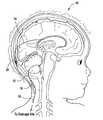
- FIG. 1Ais a partial sectional view showing a first catheter draining fluid from the lateral ventricle of the human brain, and a second catheter draining fluid from the fourth ventricle of a human brain;
- FIG. 1Bis a partial sectional view showing a first catheter draining fluid from a fluid filled cyst, and a second catheter draining fluid from the lateral ventricle;
- FIG. 2Ashows a plan view of a branched drainage conduit, with each conduit having a one-way valve that opens with a predetermined opening pressure that is greater than zero;
- FIG. 2Bshows a plan view of a branched drainage conduit, with each conduit having a one-way valve that opens with approximately zero opening pressure;
- FIG. 2Cshows a plan view of a branched drainage conduit, with one conduit having a one-way valve that opens with a predetermined opening pressure that is greater than zero and the other conduit having a one-way valve that opens with approximately zero opening pressure.
- FIGS. 1A-2Ca shunt system 10 in accordance with the present invention is illustrated.
- a first catheter 12having a proximal end and a distal end.
- the first catheterhas at least one opening adjacent to its distal end, as is known in the art.
- a second catheter 14has a proximal end and a distal end.
- the second catheteralso has at least one opening adjacent to its distal end.
- a drainage catheter 16has a proximal end and a distal end. The proximal end of the drainage catheter 16 is in fluid communication with the proximal end of the first catheter and the proximal end of the second catheter.
- a first one-way valve 18is disposed in fluid communication with the first catheter 12 between its proximal end and its at least one opening.
- the first one-way valvepermits fluid flow within the first catheter 12 from the at least one opening to the proximal end with approximately zero opening pressure.
- the first one-way valvealso effectively blocks fluid flow within the first catheter 12 from the proximal end to the at least one opening.
- a second one-way valve 20is disposed in fluid communication with the second catheter 14 between the proximal end and the at least one opening.
- the second one-way valve 20permits fluid flow within the second catheter 14 from the at least one opening to the proximal end with a predetermined opening pressure that is greater than zero.
- the second one-way valvealso effectively blocks fluid flow within the second catheter 14 from the proximal end to the at least one opening.
- the first one-way valve 18 and the second one-way valve 20can be, for example, ball and cone valves or diaphragm valves.
- the second one-way valve 20is preferably an adjustable valve so that the threshold or opening pressure that allows fluid flow through a shunt system may vary.
- the predetermined opening pressure of the second one-way valve 20can be adjusted non-invasively with means such as a wireless communications (e.g., magnetically) or a wireless telemetric communication, which includes the transfer of data or other information.
- the predetermined opening pressure of the second one-way valve 20is preferably programmable in the range from approximately 10 mmH 2 O to approximately 400 mmH 2 O, and more preferably from approximately 10 mmH 2 O to approximately 200 mmH 2 O.
- Connector 22 , 22 ′, 22 ′′that may be used to facilitate fluid handling is illustrated.
- Connector 22 , 22 ′, 22 ′′has a first port 24 , 24 ′, 24 ′′, a second port 26 , 26 ′, 26 ′′ and a third port 28 , 28 ′, 28 ′′.
- the first portis in fluid communication with the proximal end of the first catheter.
- the second portis in fluid communication with the proximal end of the second catheter, and the third port is in fluid communication with the proximal end of the drainage catheter.
- the distal end of the drainage catheteris typically placed in the peritoneum. But the fluid could be drained elsewhere in the body, or the system could be used to drain fluid externally from the body.
- a first one-way valveis placed in fluid communication with the first catheter between its proximal end and the at least one opening such that the first one-way valve permits fluid flow from the at least one opening to the proximal end with a predetermined opening pressure that is greater than zero.
- the first one-way valveeffectively blocks fluid flow from the proximal end to the at least one opening.
- a second one-way valveis placed in fluid communication with the second catheter between the proximal end and the at least one opening such that the second one-way valve permits fluid flow from the at least one opening to the proximal end with approximately zero opening pressure.
- the second one-way valveeffectively blocks fluid flow from the proximal end to the at least one opening.
- the distal end of the first cathetercan be placed, for example, in the lateral ventricle, and the distal end of the second catheter can be placed in the fourth ventricle.
- the distal end of the first cathetercan be placed, for example, in fluid communication with a fluid filled cyst 30 , and the distal end of the second catheter can be placed in the fourth ventricle.
- the two one-way valvescould both open with approximately zero opening pressure as shown in FIG. 2B .
- the two one-way valvescould both open with a predetermined opening pressure that is greater than zero as shown in FIG. 2A .
Landscapes
- Health & Medical Sciences (AREA)
- Engineering & Computer Science (AREA)
- Biomedical Technology (AREA)
- Neurology (AREA)
- Ophthalmology & Optometry (AREA)
- Otolaryngology (AREA)
- Anesthesiology (AREA)
- Heart & Thoracic Surgery (AREA)
- Hematology (AREA)
- Life Sciences & Earth Sciences (AREA)
- Animal Behavior & Ethology (AREA)
- General Health & Medical Sciences (AREA)
- Public Health (AREA)
- Veterinary Medicine (AREA)
- External Artificial Organs (AREA)
Abstract
Description
Claims (3)
Priority Applications (1)
| Application Number | Priority Date | Filing Date | Title |
|---|---|---|---|
| US12/772,847US9220877B2 (en) | 2005-08-27 | 2010-05-03 | Multi-branched anti-reflux valve |
Applications Claiming Priority (2)
| Application Number | Priority Date | Filing Date | Title |
|---|---|---|---|
| US11/212,412US20070078398A1 (en) | 2005-08-27 | 2005-08-27 | Multi-branched anti-reflux valve |
| US12/772,847US9220877B2 (en) | 2005-08-27 | 2010-05-03 | Multi-branched anti-reflux valve |
Related Parent Applications (1)
| Application Number | Title | Priority Date | Filing Date |
|---|---|---|---|
| US11/212,412DivisionUS20070078398A1 (en) | 2005-08-27 | 2005-08-27 | Multi-branched anti-reflux valve |
Publications (2)
| Publication Number | Publication Date |
|---|---|
| US20100210992A1 US20100210992A1 (en) | 2010-08-19 |
| US9220877B2true US9220877B2 (en) | 2015-12-29 |
Family
ID=37902785
Family Applications (2)
| Application Number | Title | Priority Date | Filing Date |
|---|---|---|---|
| US11/212,412AbandonedUS20070078398A1 (en) | 2005-08-27 | 2005-08-27 | Multi-branched anti-reflux valve |
| US12/772,847Active2028-04-04US9220877B2 (en) | 2005-08-27 | 2010-05-03 | Multi-branched anti-reflux valve |
Family Applications Before (1)
| Application Number | Title | Priority Date | Filing Date |
|---|---|---|---|
| US11/212,412AbandonedUS20070078398A1 (en) | 2005-08-27 | 2005-08-27 | Multi-branched anti-reflux valve |
Country Status (1)
| Country | Link |
|---|---|
| US (2) | US20070078398A1 (en) |
Families Citing this family (4)
| Publication number | Priority date | Publication date | Assignee | Title |
|---|---|---|---|---|
| DE102008030942A1 (en) | 2008-07-02 | 2010-01-07 | Christoph Miethke Gmbh & Co Kg | Cerebrospinal fluid drainage |
| DE102009060533B4 (en)* | 2009-12-23 | 2019-07-11 | Christoph Miethke Gmbh & Co Kg | Implantable shunt system |
| US20140276347A1 (en)* | 2013-03-15 | 2014-09-18 | University Of Rochester | Intraosseous shunts |
| CN110496299A (en)* | 2019-08-14 | 2019-11-26 | 福建医科大学附属第一医院 | A double-lumen catheter for continuous purification of cerebrospinal fluid |
Citations (20)
| Publication number | Priority date | Publication date | Assignee | Title |
|---|---|---|---|---|
| US2866457A (en) | 1956-12-20 | 1958-12-30 | Cutter Lab | Apparatus for administration of parenteral fluids |
| US4072153A (en) | 1976-03-03 | 1978-02-07 | Swartz William H | Post hysterectomy fluid drainage tube |
| US4432853A (en) | 1981-06-10 | 1984-02-21 | The United States Of America As Represented By The Administrator Of The National Aeronautics And Space Administration | Method of making an ion beam sputter-etched ventricular catheter for hydrocephalus shunt |
| US4595390A (en) | 1983-07-21 | 1986-06-17 | Salomon Hakim | Magnetically-adjustable cerebrospinal fluid shunt valve |
| US4615691A (en) | 1983-12-08 | 1986-10-07 | Salomon Hakim | Surgically-implantable stepping motor |
| US4681559A (en)* | 1985-12-23 | 1987-07-21 | Cordis Corporation | Plural valve three stage pressure relief system |
| US4712551A (en) | 1986-10-14 | 1987-12-15 | Rayhanabad Simon B | Vascular shunt |
| US4772257A (en) | 1983-12-08 | 1988-09-20 | Salomon Hakim | External programmer for magnetically-adjustable cerebrospinal fluid shunt valve |
| US4979937A (en) | 1987-12-22 | 1990-12-25 | Khorasani Ahmad R | Method and apparatus involving intercostal and lumbar perfusion |
| US5575767A (en) | 1994-09-16 | 1996-11-19 | Stevens; Robert C. | Method and apparatus for high pressure one-way fluid valving in angiography |
| US5755773A (en) | 1996-06-04 | 1998-05-26 | Medtronic, Inc. | Endoluminal prosthetic bifurcation shunt |
| US5906641A (en) | 1997-05-27 | 1999-05-25 | Schneider (Usa) Inc | Bifurcated stent graft |
| US5928182A (en) | 1997-07-02 | 1999-07-27 | Johnson & Johnson Professional, Inc. | Pediatric programmable hydrocephalus valve |
| US6086553A (en) | 1999-07-01 | 2000-07-11 | Akbik; Mohamad J. | Arteriovenous shunt |
| US6554790B1 (en) | 1998-11-20 | 2003-04-29 | Intuitive Surgical, Inc. | Cardiopulmonary bypass device and method |
| US20030135148A1 (en)* | 2002-01-14 | 2003-07-17 | Dextradeur Alan J. | Multi-catheter insertion device and method |
| US6689085B1 (en) | 1996-07-11 | 2004-02-10 | Eunoe, Inc. | Method and apparatus for treating adult-onset dementia of the Alzheimer's type |
| US6817985B2 (en) | 1999-03-31 | 2004-11-16 | Coaxia, Inc. | Intravascular spinal perfusion and cooling for use during aortic surgery |
| US6859953B1 (en) | 2002-09-13 | 2005-03-01 | Steven E. Christensen | Jet propulsion system for spa or jetted bath using control of air draw to Venturi jets with a three-way air control valve |
| US6866647B2 (en) | 1999-11-16 | 2005-03-15 | Coaxia, Inc. | Aortic shunt with spinal perfusion and cooling device |
Family Cites Families (20)
| Publication number | Priority date | Publication date | Assignee | Title |
|---|---|---|---|---|
| US686647A (en)* | 1901-07-05 | 1901-11-12 | William H Booth | Fishing-rod. |
| US5171415A (en)* | 1990-12-21 | 1992-12-15 | Novellus Systems, Inc. | Cooling method and apparatus for magnetron sputtering |
| US5333726A (en)* | 1993-01-15 | 1994-08-02 | Regents Of The University Of California | Magnetron sputtering source |
| US5747119A (en)* | 1993-02-05 | 1998-05-05 | Kabushiki Kaisha Toshiba | Vapor deposition method and apparatus |
| JP2642849B2 (en)* | 1993-08-24 | 1997-08-20 | 株式会社フロンテック | Thin film manufacturing method and manufacturing apparatus |
| US6221217B1 (en)* | 1995-07-10 | 2001-04-24 | Cvc, Inc. | Physical vapor deposition system having reduced thickness backing plate |
| US5985115A (en)* | 1997-04-11 | 1999-11-16 | Novellus Systems, Inc. | Internally cooled target assembly for magnetron sputtering |
| US6235634B1 (en)* | 1997-10-08 | 2001-05-22 | Applied Komatsu Technology, Inc. | Modular substrate processing system |
| US5953827A (en)* | 1997-11-05 | 1999-09-21 | Applied Materials, Inc. | Magnetron with cooling system for process chamber of processing system |
| US6730194B2 (en)* | 1997-11-05 | 2004-05-04 | Unaxis Balzers Aktiengesellschaft | Method for manufacturing disk-shaped workpieces with a sputter station |
| US6093293A (en)* | 1997-12-17 | 2000-07-25 | Balzers Hochvakuum Ag | Magnetron sputtering source |
| US6080287A (en)* | 1998-05-06 | 2000-06-27 | Tokyo Electron Limited | Method and apparatus for ionized physical vapor deposition |
| DE19830223C1 (en)* | 1998-07-07 | 1999-11-04 | Techno Coat Oberflaechentechni | Magnetron sputtering unit for multilayer coating of substrates especially in small to medium runs or in laboratories |
| US6207026B1 (en)* | 1999-10-13 | 2001-03-27 | Applied Materials, Inc. | Magnetron with cooling system for substrate processing system |
| US6238532B1 (en)* | 1999-10-29 | 2001-05-29 | International Business Machines Corporation | Radio-frequency coil for use in an ionized physical vapor deposition apparatus |
| TW584905B (en)* | 2000-02-25 | 2004-04-21 | Tokyo Electron Ltd | Method and apparatus for depositing films |
| US6641701B1 (en)* | 2000-06-14 | 2003-11-04 | Applied Materials, Inc. | Cooling system for magnetron sputtering apparatus |
| US6413380B1 (en)* | 2000-08-14 | 2002-07-02 | International Business Machines Corporation | Method and apparatus for providing deposited layer structures and articles so produced |
| EP1254970A1 (en)* | 2001-05-03 | 2002-11-06 | Unaxis Balzers Aktiengesellschaft | Magnetron sputter source having mosaic target |
| US20030029715A1 (en)* | 2001-07-25 | 2003-02-13 | Applied Materials, Inc. | An Apparatus For Annealing Substrates In Physical Vapor Deposition Systems |
- 2005
- 2005-08-27USUS11/212,412patent/US20070078398A1/ennot_activeAbandoned
- 2010
- 2010-05-03USUS12/772,847patent/US9220877B2/enactiveActive
Patent Citations (20)
| Publication number | Priority date | Publication date | Assignee | Title |
|---|---|---|---|---|
| US2866457A (en) | 1956-12-20 | 1958-12-30 | Cutter Lab | Apparatus for administration of parenteral fluids |
| US4072153A (en) | 1976-03-03 | 1978-02-07 | Swartz William H | Post hysterectomy fluid drainage tube |
| US4432853A (en) | 1981-06-10 | 1984-02-21 | The United States Of America As Represented By The Administrator Of The National Aeronautics And Space Administration | Method of making an ion beam sputter-etched ventricular catheter for hydrocephalus shunt |
| US4595390A (en) | 1983-07-21 | 1986-06-17 | Salomon Hakim | Magnetically-adjustable cerebrospinal fluid shunt valve |
| US4615691A (en) | 1983-12-08 | 1986-10-07 | Salomon Hakim | Surgically-implantable stepping motor |
| US4772257A (en) | 1983-12-08 | 1988-09-20 | Salomon Hakim | External programmer for magnetically-adjustable cerebrospinal fluid shunt valve |
| US4681559A (en)* | 1985-12-23 | 1987-07-21 | Cordis Corporation | Plural valve three stage pressure relief system |
| US4712551A (en) | 1986-10-14 | 1987-12-15 | Rayhanabad Simon B | Vascular shunt |
| US4979937A (en) | 1987-12-22 | 1990-12-25 | Khorasani Ahmad R | Method and apparatus involving intercostal and lumbar perfusion |
| US5575767A (en) | 1994-09-16 | 1996-11-19 | Stevens; Robert C. | Method and apparatus for high pressure one-way fluid valving in angiography |
| US5755773A (en) | 1996-06-04 | 1998-05-26 | Medtronic, Inc. | Endoluminal prosthetic bifurcation shunt |
| US6689085B1 (en) | 1996-07-11 | 2004-02-10 | Eunoe, Inc. | Method and apparatus for treating adult-onset dementia of the Alzheimer's type |
| US5906641A (en) | 1997-05-27 | 1999-05-25 | Schneider (Usa) Inc | Bifurcated stent graft |
| US5928182A (en) | 1997-07-02 | 1999-07-27 | Johnson & Johnson Professional, Inc. | Pediatric programmable hydrocephalus valve |
| US6554790B1 (en) | 1998-11-20 | 2003-04-29 | Intuitive Surgical, Inc. | Cardiopulmonary bypass device and method |
| US6817985B2 (en) | 1999-03-31 | 2004-11-16 | Coaxia, Inc. | Intravascular spinal perfusion and cooling for use during aortic surgery |
| US6086553A (en) | 1999-07-01 | 2000-07-11 | Akbik; Mohamad J. | Arteriovenous shunt |
| US6866647B2 (en) | 1999-11-16 | 2005-03-15 | Coaxia, Inc. | Aortic shunt with spinal perfusion and cooling device |
| US20030135148A1 (en)* | 2002-01-14 | 2003-07-17 | Dextradeur Alan J. | Multi-catheter insertion device and method |
| US6859953B1 (en) | 2002-09-13 | 2005-03-01 | Steven E. Christensen | Jet propulsion system for spa or jetted bath using control of air draw to Venturi jets with a three-way air control valve |
Also Published As
| Publication number | Publication date |
|---|---|
| US20100210992A1 (en) | 2010-08-19 |
| US20070078398A1 (en) | 2007-04-05 |
Similar Documents
| Publication | Publication Date | Title |
|---|---|---|
| US7699800B2 (en) | Multi-catheter insertion device and method | |
| US7235060B2 (en) | Hydrocephalus shunt system with endoscopic placement features | |
| JP4309649B2 (en) | Cerebrospinal fluid shunt device and hydrocephalus treatment method | |
| CA2477054C (en) | Vesicular shunt for the drainage of excess fluid | |
| JP3532219B2 (en) | Hydrocephalus treatment device | |
| AU2016204328B2 (en) | Multi-lumen ventricular drainage catheter | |
| JP4597610B2 (en) | Cutable detection catheter | |
| US5098411A (en) | Closed end hollow stylet assembly | |
| US9220877B2 (en) | Multi-branched anti-reflux valve | |
| US20040236309A1 (en) | Mesh ventricular catheter with antithrombogenic coating | |
| Børgesen et al. | Shunting to the cranial venous sinus using the SinuShunt | |
| Lee et al. | Pseudotumor cerebri patients with shunts from the cisterna magna: clinical course and telemetric intracranial pressure data | |
| Oliveira et al. | Updating technology of shunt valves | |
| US20170189655A1 (en) | System and method for draining cerebrospinal fluid | |
| US12171966B2 (en) | Cerebral spinal fluid shunt plug |
Legal Events
| Date | Code | Title | Description |
|---|---|---|---|
| AS | Assignment | Owner name:HAND INNOVATIONS LLC, FLORIDA Free format text:ASSIGNMENT OF ASSIGNORS INTEREST;ASSIGNOR:DEPUY SPINE, LLC;REEL/FRAME:030341/0713 Effective date:20121230 Owner name:DEPUY SYNTHES PRODUCTS, LLC, MASSACHUSETTS Free format text:CHANGE OF NAME;ASSIGNOR:HAND INNOVATIONS LLC;REEL/FRAME:030341/0721 Effective date:20121231 Owner name:DEPUY SPINE, INC., MASSACHUSETTS Free format text:ASSIGNMENT OF ASSIGNORS INTEREST;ASSIGNOR:CODMAN & SHURTLEFF, INC.;REEL/FRAME:030341/0689 Effective date:20121230 | |
| AS | Assignment | Owner name:DEPUY SPINE, LLC, MASSACHUSETTS Free format text:CORRECTIVE ASSIGNMENT TO CORRECT THE ASSIGNEE'S NAME PREVIOUSLY RECORDED AT REEL: 030341 FRAME: 0689. ASSIGNOR(S) HEREBY CONFIRMS THE ASSIGNMENT;ASSIGNOR:CODMAN & SHURTLEFF, INC.;REEL/FRAME:033684/0122 Effective date:20121230 | |
| AS | Assignment | Owner name:DEPUY SYNTHES PRODUCTS, INC., MASSACHUSETTS Free format text:CHANGE OF NAME;ASSIGNOR:DEPUY SYNTHES PRODUCTS, LLC;REEL/FRAME:037082/0158 Effective date:20141219 | |
| STCF | Information on status: patent grant | Free format text:PATENTED CASE | |
| AS | Assignment | Owner name:INTEGRA LIFESCIENCES SWITZERLAND SARL, SWITZERLAND Free format text:ASSIGNMENT OF ASSIGNORS INTEREST;ASSIGNOR:DEPUY SYNTHES PRODUCTS, INC.;REEL/FRAME:045167/0118 Effective date:20171002 | |
| MAFP | Maintenance fee payment | Free format text:PAYMENT OF MAINTENANCE FEE, 4TH YEAR, LARGE ENTITY (ORIGINAL EVENT CODE: M1551); ENTITY STATUS OF PATENT OWNER: LARGE ENTITY Year of fee payment:4 | |
| MAFP | Maintenance fee payment | Free format text:PAYMENT OF MAINTENANCE FEE, 8TH YEAR, LARGE ENTITY (ORIGINAL EVENT CODE: M1552); ENTITY STATUS OF PATENT OWNER: LARGE ENTITY Year of fee payment:8 |