US9220523B2 - Snaring systems and methods - Google Patents
Snaring systems and methodsDownload PDFInfo
- Publication number
- US9220523B2 US9220523B2US12/878,648US87864810AUS9220523B2US 9220523 B2US9220523 B2US 9220523B2US 87864810 AUS87864810 AUS 87864810AUS 9220523 B2US9220523 B2US 9220523B2
- Authority
- US
- United States
- Prior art keywords
- elongate element
- lumen
- pacing lead
- snaring
- section
- Prior art date
- Legal status (The legal status is an assumption and is not a legal conclusion. Google has not performed a legal analysis and makes no representation as to the accuracy of the status listed.)
- Expired - Fee Related, expires
Links
- 238000000034methodMethods0.000titleclaimsabstractdescription47
- 230000007246mechanismEffects0.000claimsabstractdescription54
- 238000000605extractionMethods0.000abstractdescription6
- 210000004731jugular veinAnatomy0.000description17
- 229910001220stainless steelInorganic materials0.000description11
- 210000005245right atriumAnatomy0.000description10
- 238000013459approachMethods0.000description8
- 210000002620vena cava superiorAnatomy0.000description7
- 239000011324beadSubstances0.000description6
- 210000003129brachiocephalic veinAnatomy0.000description5
- 210000003191femoral veinAnatomy0.000description5
- 239000000463materialSubstances0.000description5
- 210000002435tendonAnatomy0.000description5
- 239000004809TeflonSubstances0.000description4
- 229920006362Teflon®Polymers0.000description4
- 230000009471actionEffects0.000description4
- 230000009286beneficial effectEffects0.000description4
- 210000005166vasculatureAnatomy0.000description4
- 239000004677NylonSubstances0.000description3
- 230000008901benefitEffects0.000description3
- 239000011248coating agentSubstances0.000description3
- 238000000576coating methodMethods0.000description3
- 210000005003heart tissueAnatomy0.000description3
- 229920001778nylonPolymers0.000description3
- 239000004033plasticSubstances0.000description3
- 229920003023plasticPolymers0.000description3
- 230000008569processEffects0.000description3
- 239000010935stainless steelSubstances0.000description3
- 210000001519tissueAnatomy0.000description3
- 210000001631vena cava inferiorAnatomy0.000description3
- 229920002614Polyether block amidePolymers0.000description2
- 239000004698PolyethyleneSubstances0.000description2
- 210000003484anatomyAnatomy0.000description2
- 229920001903high density polyethylenePolymers0.000description2
- 239000004700high-density polyethyleneSubstances0.000description2
- 229910052751metalInorganic materials0.000description2
- 239000002184metalSubstances0.000description2
- 230000004048modificationEffects0.000description2
- 238000012986modificationMethods0.000description2
- 229910001000nickel titaniumInorganic materials0.000description2
- 210000005241right ventricleAnatomy0.000description2
- 239000007921spraySubstances0.000description2
- 239000004812Fluorinated ethylene propyleneSubstances0.000description1
- 239000004696Poly ether ether ketoneSubstances0.000description1
- RTAQQCXQSZGOHL-UHFFFAOYSA-NTitaniumChemical compound[Ti]RTAQQCXQSZGOHL-UHFFFAOYSA-N0.000description1
- 229920010741Ultra High Molecular Weight Polyethylene (UHMWPE)Polymers0.000description1
- 229920000122acrylonitrile butadiene styrenePolymers0.000description1
- 239000004676acrylonitrile butadiene styreneSubstances0.000description1
- 230000006978adaptationEffects0.000description1
- 238000005452bendingMethods0.000description1
- JUPQTSLXMOCDHR-UHFFFAOYSA-Nbenzene-1,4-diol;bis(4-fluorophenyl)methanoneChemical compoundOC1=CC=C(O)C=C1.C1=CC(F)=CC=C1C(=O)C1=CC=C(F)C=C1JUPQTSLXMOCDHR-UHFFFAOYSA-N0.000description1
- 230000000747cardiac effectEffects0.000description1
- HGAZMNJKRQFZKS-UHFFFAOYSA-Nchloroethene;ethenyl acetateChemical compoundClC=C.CC(=O)OC=CHGAZMNJKRQFZKS-UHFFFAOYSA-N0.000description1
- 230000000295complement effectEffects0.000description1
- 238000010276constructionMethods0.000description1
- 238000013461designMethods0.000description1
- 230000000694effectsEffects0.000description1
- 238000001125extrusionMethods0.000description1
- 239000012634fragmentSubstances0.000description1
- 239000002783friction materialSubstances0.000description1
- 239000011521glassSubstances0.000description1
- 229910052737goldInorganic materials0.000description1
- 230000004217heart functionEffects0.000description1
- 230000023597hemostasisEffects0.000description1
- 238000010874in vitro modelMethods0.000description1
- 238000010348incorporationMethods0.000description1
- 208000015181infectious diseaseDiseases0.000description1
- 229910052741iridiumInorganic materials0.000description1
- 239000003550markerSubstances0.000description1
- 239000011159matrix materialSubstances0.000description1
- 239000007769metal materialSubstances0.000description1
- HLXZNVUGXRDIFK-UHFFFAOYSA-Nnickel titaniumChemical compound[Ti].[Ti].[Ti].[Ti].[Ti].[Ti].[Ti].[Ti].[Ti].[Ti].[Ti].[Ni].[Ni].[Ni].[Ni].[Ni].[Ni].[Ni].[Ni].[Ni].[Ni].[Ni].[Ni].[Ni].[Ni]HLXZNVUGXRDIFK-UHFFFAOYSA-N0.000description1
- 230000037361pathwayEffects0.000description1
- 229920009441perflouroethylene propylenePolymers0.000description1
- 229910052697platinumInorganic materials0.000description1
- 239000004417polycarbonateSubstances0.000description1
- 229920000515polycarbonatePolymers0.000description1
- 229920002530polyetherether ketonePolymers0.000description1
- 229920001343polytetrafluoroethylenePolymers0.000description1
- 239000004810polytetrafluoroethyleneSubstances0.000description1
- 230000002441reversible effectEffects0.000description1
- 230000033764rhythmic processEffects0.000description1
- 238000011477surgical interventionMethods0.000description1
- 238000001356surgical procedureMethods0.000description1
- 229910052719titaniumInorganic materials0.000description1
- 239000010936titaniumSubstances0.000description1
- 238000013519translationMethods0.000description1
- 238000011282treatmentMethods0.000description1
- -1tubingSubstances0.000description1
- WFKWXMTUELFFGS-UHFFFAOYSA-NtungstenChemical compound[W]WFKWXMTUELFFGS-UHFFFAOYSA-N0.000description1
- 229910052721tungstenInorganic materials0.000description1
- 239000010937tungstenSubstances0.000description1
- 210000003462veinAnatomy0.000description1
- 230000002861ventricularEffects0.000description1
Images


Classifications
- A—HUMAN NECESSITIES
- A61—MEDICAL OR VETERINARY SCIENCE; HYGIENE
- A61B—DIAGNOSIS; SURGERY; IDENTIFICATION
- A61B17/00—Surgical instruments, devices or methods
- A61B17/22—Implements for squeezing-off ulcers or the like on inner organs of the body; Implements for scraping-out cavities of body organs, e.g. bones; for invasive removal or destruction of calculus using mechanical vibrations; for removing obstructions in blood vessels, not otherwise provided for
- A61B17/221—Gripping devices in the form of loops or baskets for gripping calculi or similar types of obstructions
- A—HUMAN NECESSITIES
- A61—MEDICAL OR VETERINARY SCIENCE; HYGIENE
- A61B—DIAGNOSIS; SURGERY; IDENTIFICATION
- A61B17/00—Surgical instruments, devices or methods
- A61B17/34—Trocars; Puncturing needles
- A61B17/3468—Trocars; Puncturing needles for implanting or removing devices, e.g. prostheses, implants, seeds, wires
- A—HUMAN NECESSITIES
- A61—MEDICAL OR VETERINARY SCIENCE; HYGIENE
- A61B—DIAGNOSIS; SURGERY; IDENTIFICATION
- A61B17/00—Surgical instruments, devices or methods
- A61B17/22—Implements for squeezing-off ulcers or the like on inner organs of the body; Implements for scraping-out cavities of body organs, e.g. bones; for invasive removal or destruction of calculus using mechanical vibrations; for removing obstructions in blood vessels, not otherwise provided for
- A61B17/221—Gripping devices in the form of loops or baskets for gripping calculi or similar types of obstructions
- A61B2017/2217—Gripping devices in the form of loops or baskets for gripping calculi or similar types of obstructions single wire changing shape to a gripping configuration
- A—HUMAN NECESSITIES
- A61—MEDICAL OR VETERINARY SCIENCE; HYGIENE
- A61N—ELECTROTHERAPY; MAGNETOTHERAPY; RADIATION THERAPY; ULTRASOUND THERAPY
- A61N1/00—Electrotherapy; Circuits therefor
- A61N1/02—Details
- A61N1/04—Electrodes
- A61N1/05—Electrodes for implantation or insertion into the body, e.g. heart electrode
- A61N1/056—Transvascular endocardial electrode systems
- A61N1/057—Anchoring means; Means for fixing the head inside the heart
- A61N2001/0578—Anchoring means; Means for fixing the head inside the heart having means for removal or extraction
Definitions
- Embodiments of the present applicationrelate generally to systems and methods for separating or removing an object from a patient, and more specifically, to techniques for grasping pacing leads within a patient.
- a pacemakercan be used to improve heart function in a patient.
- a pacemakercan transmit electrical signals to the patient's heart, so as to assist the heart to beat in a desired heart rhythm.
- a pacing systemtypically includes a pacemaker, a pacing lead, and a controller or processor.
- a pacing leadoften has a wire that transmits electrical impulses to cardiac tissue.
- a pacing leadmay transmit information regarding cardiac activity to the pacemaker or processor.
- a pacing leadit may be desirable or necessary to remove a pacing lead from a patient.
- a patientmay develop an infection in tissue which is contacting the pacing lead or pacemaker. It may also be advantageous to remove the lead or lead fragment if the lead breaks or otherwise poses a risk of damage, discomfort, or obstruction or interference, if the lead interferes with the operation of another implanted device, or if the patient's vasculature or tissue which is located at or near the lead becomes obliterated or occluded.
- a leadmay develop or present a free end, which can occur when a lead breaks, is pulled out of a header, or is otherwise abandoned during a surgical intervention. If a lead has a free end, it is typically located in the brachiocephalic vein. To remove a lead having a free end, it may be desirable for the physician or operator to navigate the free end of the lead toward an incision site.
- pig tail cathetersmay have a limited holding capability, and the lead may slip out of the catheter before it is freed from the patient's anatomy.
- pig tail catheterscan tend to straighten out when pulled by the operator, thus disengaging the lead from the pig tail.
- Some snaresgrasp the lead with inappropriate levels of force.
- Embodiments of the present inventionprovide or intravascular hook or snaring solutions that address the problems which may be associated with the techniques described above, and hence provide answers to at least some of these outstanding needs.
- Grasping snares and method for grasping a pacing lead and removing it from the bodyare disclosed herein.
- an operatormay advance a snaring system through a jugular access site in a patient, providing a relatively non-tortuous pathway to the superior vena cava where the snaring system can be engaged with a pacing lead.
- the pacing leadwhich optionally may involve pulling the lead so as to disengage a proximal portion or a distal portion of the lead from an attachment site within the patient.
- the physiciancan maneuver the free end toward the access site, by loosely engaging the snaring system with the pacing lead. In some cases, this may involve the use of a snaring system having one or more roller bearings or sleeves.
- the snaring systemcan be translated along a length of the pacing lead, and can be used to maneuver or pull a free end of the pacing lead, without transmitting an excessive amount of pulling force or stress on the opposing secured end of the pacing lead.
- Such grasping snaresmay be operated with significant pulling forces, while maintaining an engagement with a pacing lead.
- Exemplary snaring systemsinclude a snare wire with a hooked distal end that is slidable within the wall or lumen of an outer sheath or jacket. Such arrangements permit the distal end of the snare wire to be moved distally away from the outer jacket in order to snare the pacing lead. Once grasped, the pacing lead can be pulled back into the inner lumen of the outer jacket so that it can be withdrawn from the body.
- Embodiments of the present inventionalso encompass deflection tendons or bending wires that can be incorporated into the outer jacket to bend or deflect the distal tip of the outer jacket.
- Embodimentsmay also include snares having a closed hook at their distal end.
- a distal end or snare hookmay have one or more rotatable bearings.
- a snarecan be inserted into the jugular vein of a patient. The snare can be used to grasp or engage the pacing lead and pull one end out through the jugular vein access site. Once the lead end is extending outside the body, typical lead extraction techniques can be employed. In some cases, grasping snare wires can be extended or advanced through a wall of a catheter body.
- embodiments of the present inventionencompass systems and methods for snaring or grasping a lead which is disposed within an anatomical location of the patient, such as the jugular vein, the superior vena cava, the right atrium, the right ventricle, the brachiocephalic vein, or the like.
- the techniques disclosed hereinallow a surgeon or operator to effectively grasp, push, pull, twist, rotate, or otherwise maneuver or manipulate an object, such as a pacing lead, within the patient.
- snaring systems disclosed hereincan withstand high pulling forces without releasing a pacing lead, and can effectively snare a lead in a midsection or central portion, without being threaded over the end of the pacing lead.
- Exemplary snaring systemsallow a pacing lead to slide through a distal hook of a snare wire, without imparting high forces to the pacing lead or adhered vasculature.
- Featuressuch as a hook tag end and a bent or shaped snare wire allow an operator to effectively steer or navigate the snare system to the pacing lead for capture.
- snaring systems disclosed hereinare easily releasable from the pacing lead.
- snaring systemscan include a hook or snare that can hook and retain a pacing lead, and pull a portion of the pacing lead downward toward the femoral vein or upward toward the jugular vein and out of the access site.
- Systemscan also allow the pacing lead to move through a snare wire or catch mechanism as the lead is being pulled or during the snaring process.
- Exemplary embodimentscan also release a hook or snare if the procedure is not successful or is interrupted.
- an exemplary snaring systemincludes an elongate element having a proximal end and a distal end.
- the distal endcan include a loop.
- the systemalso includes an outer sheath having a central lumen.
- the central lumencan be configured to receive at least a portion of the loop of the distal end of the elongate element.
- a systemmay also include a rotatable bearing in operative association with the loop of the distal end of the elongate element.
- the distal end of the elongate elementcan include a tag, and the central lumen of the outer sheath can be configured to receive the tag.
- the outer sheathincludes a second lumen extending through a side wall of the sheath, and the second lumen is configured to receive at least a portion of the elongate element.
- the elongate elementincludes a flattened portion, a square cross section portion, or a rectangular cross section portion.
- the systemmay include a deflection mechanism coupled with the outer sheath.
- embodiments of the present inventionencompass systems and methods for engaging a pacing lead disposed within a patient.
- An exemplary methodincludes inserting a snaring system through a jugular or femoral access site of a patient, engaging a pacing lead with the snaring system, sliding the snaring system along a length of the pacing lead so as to move a portion of the pacing lead toward the jugular or femoral access site of the patient, and withdrawing the snaring system from the jugular or femoral access site so as to remove at least a portion of the pacing lead from the patient.
- the step of engaging the pacing leadcan include engaging the pacing lead with a roller mechanism of the snaring system. In some cases, the step of engaging the pacing lead can include engaging the pacing lead with a capture mechanism of the snaring system.
- the capture mechanism of the snaring systemcan include an elongate element having a loop. In some cases, the step of engaging the pacing lead can include sliding the elongate element along a side wall lumen of a catheter of the snaring system.
- An exemplary methodmay include inserting a snaring system through an access site of a patient.
- the snaring systemcan include an elongate element having a distal loop and a rotatable roller mechanism disposed along the distal loop of the elongate element.
- the methodmay also include engaging the object with rotatable roller mechanism of the snaring system, and withdrawing the snaring system toward the access site so as to move at least a portion of the object toward the access site.
- the elongate elementmay include a tag end that is disposed distal to the rotatable roller mechanism.
- the rotatable roller mechanismmay include a bearing having a tubular shape.
- the rotatable roller mechanismmay include a bearing having a spherical shape.
- the rotatable roller mechanismincludes a first cylindrical bearing defining a first central longitudinal axis and a second cylindrical bearing defining a second central longitudinal axis.
- the first central longitudinal axiscan be angularly offset from the second central longitudinal axis.
- the first central longitudinal axisis angularly offset from the second central longitudinal axis by about 90 degrees.
- embodiments of the present inventionencompass a snaring system for engaging an object within a patient's body, which includes an elongate element having a proximal end and a distal end.
- the distal end of the elongate elementcan include a loop and a tag.
- the snaring systemmay also include a rotatable bearing in operative association with the loop of the distal end of the elongate element.
- the rotatable bearingis disposed on a first section of the loop, and the loop has a second section distal to the first section and a third section proximal to the first section, such that the second section and the third section are in substantial parallel alignment.
- the first sectionis in substantial perpendicular alignment with each of the second section and the third sections.
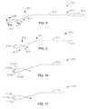
- FIGS. 1A to 1Fillustrates aspects of object grasping or removal systems and methods according to embodiments of the present invention.
- FIG. 2illustrates aspects of an object removal system or grasping snare according to embodiments of the present invention.
- FIGS. 3A to 3Dillustrate aspects of an object removal system or grasping snare according to embodiments of the present invention.
- FIGS. 4A and 4Billustrate aspects of a grasping snare system according to embodiments of the present invention.
- FIGS. 5A and 5Billustrate aspects of a grasping snare system according to embodiments of the present invention.
- FIG. 6illustrates aspects of an object removal or snaring system according to embodiments of the present invention.
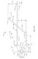
- FIGS. 7A and 7Billustrates aspects of pacing lead snaring or removal systems and methods according to embodiments of the present invention.
- FIG. 8depicts aspects of a snaring system according to embodiments of the present invention.
- FIG. 9depicts aspects of a snaring system according to embodiments of the present invention.
- FIG. 10depicts aspects of a snaring system according to embodiments of the present invention.
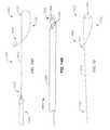
- FIGS. 11 to 11Cdepict aspects of a snaring system according to embodiments of the present invention.
- FIGS. 12A to 12Cdepict aspects of a snaring system according to embodiments of the present invention.
- FIGS. 13A and 13Bdepict aspects of a snaring system according to embodiments of the present invention.
- FIGS. 14A and 14Bdepict aspects of a snaring system according to embodiments of the present invention.
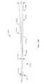
- FIGS. 15 to 15Cdepict aspects of a snaring system according to embodiments of the present invention.
- a patientmay present with a pacing lead that is no longer disposed within the pocket, but instead is freely floating in the brachiocephalic vein, the superior vena cava, the right atrium, or the like.
- Embodiments of the present inventionprovide techniques for grasping a free end of the pacing lead and maneuvering or pulling it toward the jugular vein.
- Exemplary approachesprovide removal or snare systems that can hook, grasp, push, pull, and twist a pacing lead. Such advances allow an operator may degrees of freedom when removing a lead having a free end.
- techniquesmay include pulling the free end of the lead down from the femoral vein using a femoral vein approach.
- the physiciancan use a snare device inserted through the jugular vein to grasp or engage the lead and pull it toward an opening or incision in the jugular vein.
- the free end of the leadcan be pulled back up through the jugular vein, via the inferior vena cava, right atrium, and superior vena cava.
- this techniquecan involve using a first snare to hook the lead and pull the lead down through the inferior vena cava and into the femoral vein.
- the techniquecan also involve using a second snare to grasp or engage the end of the lead from a jugular access site, and pull the free end up through the jugular access site.
- a laser sheath or other removal devicecan then be used over the lead to free or dislodge the distal end of the lead for removal.
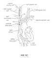
- FIGS. 1A to 1Fillustrates aspects of an object grasping or removal system 100 according to embodiments of the present invention.
- FIG. 1Ashows a pacing lead 10 disposed within a patient's body, such that a free end 12 of the lead is floating freely within the brachiocephalic vein.
- an object grasping or removal system 100can be advanced within the jugular vein, and then used to snare, grasp, hook, or otherwise engage the pacing lead.
- grasping or removal system 100is used to grasp or engage pacing lead 10 at or near a central portion 14 of the pacing lead.
- grasping or removal system 100can be used to grasp or engage a portion of pacing lead 10 which is disposed at or near the right atrium, or at or near the superior vena cava.
- object grasping or removal system 100includes an outer sheath 110 and a catch mechanism 120 .
- the catch mechanismis extended from the outer sheath, so that it may contact, hook, or engage the pacing lead.
- catch mechanism 120can be activated, for example by withdrawing it into outer sheath 110 , so as to capture, secure, or engage the pacing lead. While pacing lead 10 is engaged or firmly held by grasping or removal system 100 , the operator may manipulate the removal system so as maneuver the pacing lead as desired. In some cases, it may be desirable or beneficial for the physician to administer a pulling action, wherein the pacing lead is not firmly grasped by the snaring system, but instead is more loosely engaged by the snaring system, such that he snaring system allows movement of the pacing lead through a snaring loop of the system during withdrawal of the lead. As shown in FIG.
- FIG. 1Cillustrates the operator can push grasping or removal system 100 into or toward the right atrium, in the direction illustrated by arrow A, thus advancing the pacing lead into or toward the right atrium. Subsequently, free end 12 of pacing lead 10 is withdrawn from the brachiocephalic vein and into or near the right atrium, as illustrated in FIG. 1D .
- FIG. 1Dillustrates the situation where a proximal portion of the pacing lead becomes freed
- embodiments of the present inventionalso encompass situations where instead, or in addition, a distal portion of the pacing lead becomes freed. For example, when physician uses the snaring system to pull on the pacing lead, the distal end of the pacing lead may become dislodged or separated from the cardiac tissue.
- the surgeonmay adjust the positioning of the object grasping or removal system on the pacing lead.
- catch mechanism 120can be released or relaxed, for example by extending it from outer sheath 110 .
- the catch mechanismis in an open configuration, and the grasping or object removal system can be repositioned as desired at another location along the pacing lead.
- grasping or object removal systemis repositioned toward free end 12 of pacing lead 10 .
- the operatormay slide the grasping or removal system along the pacing lead to achieve the desired repositioning.
- the operatormay activate catch mechanism 120 so as to firmly secure or grasp pacing lead 10 with removal system 100 , as shown in FIG. 1F .
- the operatormay then pull or withdraw the pacing lead through the jugular vein, and toward a jugular access site, in direction indicated by arrow A.
- the operatormay then use the jugular access site to pass a laser sheath or other lead removal device along grasping or removal system 100 .
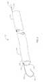
- an object removal system or grasping snare 200can include an outer sheath 210 such as a jacket or tube, and a catch mechanism 220 such as an snare wire.
- catch mechanism 220includes an internal wire having a distal hook.
- the internal wirecan run along a length of the tube, and the wire can be configured to move axially within the tube.
- the wirecan slide along an inner wire lumen 212 of the tube.
- the distal end 222 of the wire 220 which includes the hookcan also be received or disposed within a catch lumen 214 of the tube.
- the distal hookcan be extended from a distal portion 216 of the tube, and retracted back toward or into the tube.
- the wirecan have a proximal end 224 , which extends from a proximal portion 218 of tube 210 , that includes a loop or pull mechanism 226 such as a pull or torque handle.
- Outer jacket or tube 210can be used by the operator to support or carry snare wire 220 , and to provide push, pull, and rotation movements.
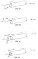
- FIG. 3Aillustrates an object removal system or grasping snare 300 having an outer tube 310 and a snare wire 320 .
- the catch mechanism or snare wire 320is in an open position.
- FIG. 3Balso shows snare wire 320 in an open position, wherein the snare wire is rotated about 180 degrees relative to the configuration shown in FIG. 3A .
- a distal hook 322can assist in functioning as a grasping snare or a hook snare.
- the operatorcan pull the snare wire toward the outer tube, as shown in the closing position or configuration depicted in FIG. 3C .
- the hookcan be moved along a length of the pacing lead, or the hook can be used to maneuver the positioning of the pacing lead, without applying a significant pulling or pushing force to the pacing lead, or to an affixed or embedded portion of the pacing lead.
- the operatorcan pull snare wire 320 further into tube 310 , thus firmly grasping the lead, as shown in the closed position or configuration depicted in FIG. 3D .
- the grasping snare 300can then be used to push, pull, twist, or otherwise maneuver pacing lead 330 .
- the operatorcan extend the distal hook of the wire from the tube, for example by pushing it forward relative to the tube, thus exposing the hook.
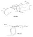
- grasping snare system 400can include an outer tube 410 and an inner snare wire 420 .
- Snare wire 420can be rotated relative to tube 410 as indicated by arrow A, optionally via rotation of a wire handle 426 as indicated by arrow A shown in FIG. 4B .
- snare wire 420can be translated relative to tube 410 as indicated by arrow B shown in FIG. 4A , optionally via translation of wire handle 426 as indicated by arrow B shown in FIG. 4B .
- snare system 400can include a seal disposed toward a proximal end of tube 410 , or a luer fitting that accepts a rotating hemostasis valve.
- tube or outer jacket 410 of snare system 400may have two lumens, for example a wire lumen 412 and a capture lumen 414 .
- wire lumen 412can be laterally offset from a central longitudinal axis 416 of the outer jacket.
- wire lumen 412can be disposed within a wall 418 of jacket 410 .
- snare wire 420can be constrained to or contained within one side of the tube.
- Such tube configurationcan also allow a distal hook 422 of the wire to be rotated outside the axis or silhouette defined by the outer diameter 419 of the tube, so as to provide a larger snaring area.
- Wire lumen 412 within the tubecan present a slot configuration.
- wire lumen 512 acan present an oval shaped cross section.
- wire lumen 512 bcan present a square or rectangular shaped cross section.
- Such shaped inner wire lumens 512 a , 512 bcan be formed during an extrusion process, or reformed with an insert.
- the snare wirecan include a shaped portion, which presents a similarly shaped ovular or rectangular profile.
- FIG. 4Ait is possible to provide a flattened portion 423 at or near the distal curve section 422 of the snare wire 420 to key it into the lumen or slot 412 in the side or wall of outer jacket 410 . In this way, snare wire 420 can be keyed with tube 410 .
- Such modificationscan increase the surface area on the outer or top portion of the loop 422 to prevent or inhibit snare wire 420 from cutting into or stripping the pacing lead.
- a flattened or shaped portioncan be can be placed on the distal section of the wire to key the snare wire to the tube.
- a section of the wire proximal to the flattened or shaped portioncan be round or rounded in shape, so as to allow the snare wire to be rotated relative to the tube within the inner wire aperture, when the flattened or shaped section is distal to the tube lumen.
- the snare wire and slot 412may present square cross-section shapes, rectangular cross-section shapes, and other complementary interlocking or keyed shapes.
- such keyed snaring systemsmay include roller bearings or sleeves as described elsewhere herein, for example with reference to FIGS. 9 to 11C , and 15 to 15 C.
- snare wire 420 or loop area 422can include a slip coating or reduced friction surface, to allow the snare to slide along the lead, for example when the snare is being opened or closed.
- a coating or surfacecan include PTFE, Teflon, Teflon spray, paralene, or any suitable reduced-friction spray, tubing, coating, or solution.
- Outer jacket or tube 410can be constructed of one or materials including Pebax, ABS, PEEK, FEP, PE, Nylon, a Pebax braid matrix, or the like.
- the outer diameter (OD) of the tubecan be within a range from about 0.090 inches to about 0.160 inches. In some cases, the outer diameter of the tube can be sized so as to allow a laser sheath, which may be 12 Fr to 16 Fr, to pass over the snaring assembly. For example, the outer diameter can be sized to allow a 12 Fr laser sheath pass over the tube 410 .
- the snare wirecan be constructed of one or more materials such as stainless steel, NiTi, or the like. The outer diameter (OD) of the wire can be within a range from about 0.010 inches to about 0.050 inches. The wire can be configured to provide sufficient strength to pull on a pacing lead while providing sufficient flexibility to navigate the patient's anatomy.
- Snaring system 600includes an outer tube 610 , a snare wire or capture mechanism 620 , and a deflection mechanism 650 .
- the deflection mechanismmay include, for example, a pull wire or a steering tendon 660 .
- Deflection mechanism 650can provide to the snare system an additional degree of freedom while manipulating the snare system to grasp a pacing lead.
- a deflection mechanismcan include a tendon wire that is housed in a wall of outer tube 610 , for example within a deflection mechanism lumen 616 , and anchored at some point distal, for example at an anchor point 618 .
- the location of anchor point 618 along the length of tube 610can be determined by the radius of curvature desired during operation of the deflection mechanism. For example, as the anchor point is located more closely to a distal end 619 of tube 610 , it is possible to achieve a bend in tube 610 having a smaller radius of curvature when actuating the deflection mechanism.
- anchor point 618can be located within 20 cm of the distal end of tube 610 .
- anchor point 618may include an embedded eyelet or an anchor band. Anchor point 618 can serve to fix a distal portion of the pull wire relative to the outer tube.
- deflectioncan be effected by applying tension to a proximal end 652 of the tendon wire, for example by pulling the wire in the direction indicated by arrow A, which in turn causes the distal end of the tube to deflect in the direction indicated by arrow B.
- the tendon wirecan have a diameter within a range from about 0.005 inches to about 0.030 inches, according to some embodiments.
- the tensioncan be applied by through the use of a mechanical mechanism or through the use of manual force provided directly by the user.
- a mechanical deflection mechanismcan include a screw, a cam or cylindrical disk, a lever, or other mechanical means to tension a wire.
- a mechanical deflection mechanismcould be mounted in a housing to create a handle.
- a handlecan be configured to lock the tube in a deflected configuration as desired during a surgical procedure, and until the operator unlocked the tube from the deflected orientation.
- a snare systemmay include a pre-shaped outer tube that can be straightened or shaped by advancing a straight or shaped mandrel through a lumen in the wall of the outer tube. The degree of straightening, or deflection, can be controlled by the distance or extent to which the mandrel is advanced distally into the wall or lumen of the outer tube.
- a mandrelcan be integrated with the outer tube, yet allow it to be slidable.
- a mandrelcan be an auxiliary member that is removable. A distal end of the mandrel can be made with a ball-end tip to prevent or inhibit it from perforating the outer tube when it is advanced.
- Snaring systemswhich include shaped wire element such as those depicted in FIGS. 2 , 3 A to 3 D, 4 A, and 6 are well suited for loosely engaging and maneuvering a pacing lead without subjecting the pacing lead to significant pulling forces. Such systems are particularly useful in pacing lead removal methods such as those described herein with reference to FIGS. 7A and 7B .
- the physicianmay be desirable or beneficial for the physician to administer a pulling action, wherein the pacing lead is not firmly grasped by the snaring system, but instead is more loosely engaged by the snaring system, such that the snaring system allows movement of the pacing lead through a snaring loop of the system as the system is navigated or manipulated by the physician.
- an elongate element or hooked wire of the snaring systemcan be inserted into the vasculature through a snaring system sheath, either from a jugular vein or femoral vein access site.
- the distal hook or loopcan be placed near the pacing lead at or near the vicinity of the superior vena cava.
- a distal loop 712 of snaring system 710can be used to hook a central portion 704 of the pacing lead, optionally by maneuvering or manipulating a control handle 714 of the snaring system.
- the snaring wirecan be rotated via a handle or pin vice 714 so that a hook tag end of distal portion 712 catches the lead. The operator can pull up on the snare wire or snaring system to cause the pacing lead to slide into the enclosed area of the distal hook.
- the snaring systemcan be retracted or pulled up in the direction indicated by arrow A, so as to withdraw proximal portion 703 of the pacing lead away from the pacemaker pocket, and into the jugular vein.
- distal loop 712 of the snaring systemcan slide along a length of the pacing lead, from central portion 704 toward proximal portion 703 , as indicated by arrow B.
- FIG. 7A and 7Billustrate the situation where a proximal portion of the pacing lead becomes freed
- embodiments of the present inventionalso encompass situations where instead, or in addition, a distal portion of the pacing lead becomes freed.
- a distal portion of the pacing leadbecomes freed.
- physicianuses the snaring system to pull on the pacing lead, the distal end of the pacing lead may become dislodged or separated from the cardiac tissue.
- a sheathcan be placed over the snaring wire and advanced over the tag end of the distal hook, so as to cinch or secure the pacing lead to the snaring system.
- the sheath and snaring wirecan then be pulled to free the proximal portion of the pacing lead. Once free, the snaring wire and sheath can be pulled out of the body access site along with the proximal end of the pacing lead.
- the entire pacing leadcan be extracted via lead extraction techniques, for example via laser lead extraction.
- the operatorcan push and rotate the snaring wire to release the hook from the pacing lead.
- FIG. 8depicts a snaring system 800 according to embodiments of the present invention.
- Snaring system 800includes an elongate element or wire 810 having a proximal portion 812 and a distal portion 814 .
- System 800can include a pin vice or handle 820 coupled with proximal portion 812 of elongate element 810 .
- distal portion 814 of elongate element 810includes a looped or hooked portion 815 .
- Distal portion 814can also include a tag end 816 .
- elongate element 810includes a stainless steel wire having a diameter of about 0.020 inches.
- Looped portion 815can have a length L of about 0.5 inches and a width W of about 0.2 inches.
- tag end 816can have a length LT of about 0.25 inches. In some cases, tag end 816 can have a length LT of about 0.50 inches.
- FIG. 9depicts a snaring system 900 according to embodiments of the present invention.
- Snaring system 900includes an elongate element or wire 910 having a proximal portion 912 and a distal portion 914 .
- System 900can include a handle 920 coupled with proximal portion 912 of elongate element 910 .
- distal portion 914 of elongate element 910includes a looped or hooked portion 915 .
- Distal portion 914can also include a tag end 916 .
- System 900further includes a bearing or sleeve 919 disposed about a section of distal portion 914 . In some cases, bearing 919 can rotate about elongate element 910 .
- Bearing 919can provide reduced friction between elongate element 910 and a pacing lead.
- Elongate element 910can include one or more bends 911 which can enhance steerability of the snaring system.
- a bearing elementcan include a metal material, such as stainless steel, titanium, or the like.
- a bearing elementmay include a plastic material, such as Teflon, nylon, polycarbonate, high-density polyethylene (HDPE), ultra high molecular weight polyethylene (UHMWPE), or the like.
- a bearing or sleevecan have a cylindrical or tubular shape.
- a bearingcan present a cylindrical shape, having a diameter with a range from about 0.04 inches to about 0.12 inches.
- bearing or sleeve 1019 amay define, for example by way of an internal lumen, a central longitudinal axis 1019 ai
- bearing or sleeve 1019 bmay define, for example by way of an internal lumen, a central longitudinal axis 1019 bi
- Axis 1019 aimay be angularly offset from axis 1019 bi .
- FIG. 11illustrates a snaring system 1100 which includes three bearings or sleeves 1119 a , 1119 b , 1119 c disposed about an elongate element 1110 .
- One or more of the bearingsmay present a spherical shape.
- bearing 1119 bcan present a spherical shape having a diameter within a range from about 0.04 inches to about 0.10 inches.
- Snaring systems having roller bearings or sleevescan allow a physician to apply significant pulling forces to the catheter, while still maintaining an operable engagement between the snaring system and the pacing lead.
- the roller bearing or sleevecan act to dissipate a portion of the applied force, such that a reduced amount of force is applied to the pacing lead itself.
- elongate element 810can have a radiused bottom or distal looped portion.
- elongate element 910can have a straight bottom or distal looped portion.
- elongate element 1010can have an angled bottom or distal looped portion, such that a first straight section is angularly offset from a second straight section by about 90 degrees.
- the snaring systemwhich presents two roller bearings 1019 a , 1019 b that can simultaneously contact a pacing lead, provides roller bearings edges that are angularly offset from one another by about 90 degrees.
- FIG. 10which presents two roller bearings 1019 a , 1019 b that can simultaneously contact a pacing lead
- elongate element 1110can have an angled bottom or distal looped portion, such that a first straight section is angularly offset from a second straight section by about 90 degrees.
- the snaring systemwhich presents three roller bearings 1119 a , 1119 b , 1119 c that can simultaneously contact a pacing lead, provides cylindrical roller bearings edges that are angularly offset from one another by about 90 degrees.
- the bottom or distal looped portionsare appropriately sized to accommodate a pacing lead.
- a bottom or distal looped portionmay have a length L that is about twice as long as a width W.
- the looped or hooked portion 815may have a length L of about 0.5 inches and a width W of about 0.2 inches.
- the incorporation of an increased number of rollers or bearings, for example as depicted in FIG. 11allows the operator to pull the snaring system along a pacing lead using a correspondingly reduced amount of force.
- Snaring systemswhich include a roller bearing or sleeve as described herein are well suited for loosely engaging and maneuvering a pacing lead without subjecting the pacing lead to significant pulling forces. Such systems are particularly useful in pacing lead removal methods such as those described herein with reference to FIGS. 7A and 7B .
- it may be desirable or beneficial for the physician to administer a pulling actionwherein the pacing lead is not firmly grasped by the snaring system, but instead is more loosely engaged by the snaring system, such that he snaring system allows movement of the pacing lead through a snaring loop of the system as the system is navigated or manipulated by the physician.
- snare systemscan include a closed hook and tag end which can be used to grab a pacing lead or otherwise allow the pacing lead entry into the hook.
- An elongate element or wiremay include a medical grade wire constructed of stainless steel, Nitinol, or the like.
- the elongate element or wirecan be tapered from a larger diameter on a proximal portion or end to smaller diameter on a distal portion or end, and may have varying diameters along the length of the wire to add flexibility or strength where needed or desired.
- the constructioncan also include a central core mandrel, which may also be tapered or of varying diameter, which in turn is covered with a coil.
- a tag endmay present an atraumatic configuration. In some cases, a tag end may terminate in a ball end. In some cases, a tag end may terminate in a pig tail configuration or a flexible coil. Atraumatic configurations can help to prevent or inhibit perforation of the vasculature.
- FIG. 11Aillustrates side view of a snaring system 1100 a according to embodiments of the present invention.
- snaring system 1100 aincludes an elongate element or wire 1110 a having a proximal portion 1112 a and a distal portion 1114 a .
- System 1100 acan include a pin vice or handle (not shown) coupled with proximal portion 1114 a of elongate element 1110 a .
- distal portion 1114 a of elongate element 1110 aincludes a looped or hooked portion 1115 a .
- Distal portion 1114 acan also include a tag end 1116 a .
- elongate element 1110 aincludes a stainless steel wire having a diameter of about 0.020 inches. Looped portion 1115 a can have a first length L 1 of about 0.41 inches and a second length L 2 of about 0.19 inches. As shown here, tag end 1116 a extends from a central portion 1113 a of elongate element 1110 a to a distance ET of about 0.22 inches.
- Snaring system 1100 aincludes three bearings or sleeves 1120 a , 1120 b , 1120 c disposed about an elongate element 1110 a . Snaring system 1100 a also includes a distal bead or spherical mechanism 1130 a disposed on a distal portion of elongate element 1110 a.
- Bearing 1120 apresents a cylindrical or barrel shape having a diameter within a range from about 0.04 inches to about 0.10 inches.
- bearing 1120 acan have a diameter of about 0.07 inches.
- bearing 1120 acan have a length of about 0.12 inches.
- an end portion of bearing 1120 apresents a radius of curvature of about 0.2 inches.
- Bearing 1120 bpresents a spherical or oblate shape having a diameter within a range from about 0.04 inches to about 0.10 inches.
- bearing 1120 bcan have a diameter of about 0.07 inches.
- bearing 1120 bcan have a length of about 0.06 inches.
- Bearing 1120 cpresents a cylindrical or barrel shape having a diameter within a range from about 0.04 inches to about 0.10 inches.
- bearing 1120 ccan have a diameter of about 0.07 inches.
- bearing 1120 ccan have a length of about 0.19 inches.
- elongate element 1110 acan have an angled bottom or distal looped portion, such that a first section 1151 a is angularly offset from a second section 1152 a .
- second section 1152 ais angularly offset from a third section 1153 a , which is angularly offset from a fourth section 1154 a .
- fourth section 1154 ais angularly offset from a fifth section 1155 a , which is angularly offset from a sixth section 1156 a .
- fourth section 1154 a and fifth section 1155 a of elongate element 1110 adefine an angle of about 157.4 degrees
- fifth section 1155 a and sixth section 1156 a of elongate element 1110 adefine an angle of about 130 degrees.
- Distal bead or spherical mechanism 1130 acan present a radius of curvature of about 0.03 inches.
- the bottom or distal looped portions of the elongate element, optionally in combination with the bearings,are appropriately sized or configured to accommodate a pacing lead.
- FIG. 11Billustrates a perspective view of a snaring system 1100 b according to embodiments of the present invention.
- snaring system 1100 bincludes an elongate element or wire 1110 b having a proximal portion 1112 b and a distal portion 1114 b .
- System 1100 bcan include a pin vice or handle (not shown) coupled with proximal portion 1114 b of elongate element 1110 b .
- distal portion 1114 b of elongate element 1110 bincludes a looped or hooked portion 1115 b .
- Distal portion 1114 bcan also include a tag end 1116 b .
- elongate element 1110 bincludes a stainless steel wire having a diameter of about 0.020 inches.
- Elongate element 1110 b and looped portion 1115 bcan present geometrical configurations similar to those described above with reference to FIG. 11A .
- Snaring system 1100 bincludes three bearings or sleeves 1121 a , 1121 b , 1121 c disposed about an elongate element 1110 b .
- Snaring system 1100 balso includes a distal bead or spherical mechanism 1130 b disposed on a distal portion of elongate element 1110 b .
- the bearings and bead mechanismscan present geometrical configurations similar to those described above with reference to FIG. 11A .
- FIG. 11Cillustrates a top view of a snaring system 1100 c according to embodiments of the present invention.
- snaring system 1100 cincludes an elongate element or wire 1110 c having a proximal portion 1112 c and a distal portion 1114 c .
- System 1100 ccan include a pin vice or handle (not shown) coupled with proximal portion 1114 c of elongate element 1110 c .
- distal portion 1114 c of elongate element 1110 cincludes a looped or hooked portion 1115 c .
- Distal portion 1114 ccan also include a tag end 1116 c .
- elongate element 1110 cincludes a stainless steel wire having a diameter of about 0.019 inches.
- Elongate element 1110 c and looped portion 1115 ccan present geometrical configurations similar to those described above with reference to FIG. 11A .
- Snaring system 1100 cincludes three bearings or sleeves 1122 a , 1122 b , 1122 c disposed about an elongate element 1110 c .
- Snaring system 1100 calso includes a distal bead or spherical mechanism 1130 c disposed on a distal portion of elongate element 1110 c .
- the bearings and bead mechanismscan present geometrical configurations similar to those described above with reference to FIG. 11A .
- tag end 1116 ccan be offset from a central portion 1113 c of elongate element 1110 c at an angle of about 5 degrees.
- a hookcan be radiopaque, for example by either being constructed of a base material having a suitable thickness, or by incorporating radiopaque material.
- a hook or elongate elementcan contain radiopaque marker bands placed at appropriate or desired locations along the element.
- a hook or coilcan include a radiopaque metal such as Pt, Au, Ir, Tungsten, or the like.
- snaring systemscan also include a hook or elongate element in conjunction with one or more bearing surfaces.
- a bearing or sleevecan include a low friction material such as Teflon, PE, nylon, or the like, optionally in a tubular or sheath configuration.
- the bearing or sleevecan be disposed or placed over the wire or elongate element.
- a bearing or sleevecan be placed or positioned over a hard metal or plastic component mounted on the wire or elongate element, and can be designed or configured to rotate when a pacing lead is pulled out of the body with the snare system.
- a snare systemcan include an outer jacket, such as a plastic sheath.
- FIG. 12Aillustrates aspects of a snaring system 1200 according to embodiments of the present invention.
- Snaring system 1200includes an outer jacket or sheath 1210 and a capture mechanism or elongate element 1220 .
- An operatorcan position the snaring system so as to capture a portion of a pacing lead 1250 with a hook tag end 1226 of the elongate element.
- FIG. 12Ban operator can maneuver the snaring system, for example by pulling and rotating the elongate element, so as to enclose pacing lead 1250 within a distal loop 1225 of the elongate element.
- an operatorcan maneuver the snaring system, for example by advancing or translating sheath 1210 relative to elongate element 1220 , so as to bring distal loop 1225 toward sheath 1210 , such that hook tag end 1226 is received within the sheath, and pacing lead 1250 is securely grasped by distal loop 1225 .
- distal loop 1225operates to squeeze or press the pacing lead against a distal end 1212 of sheath 1210 .
- Snaring systemswhich include a hook tag end as described herein are well suited for loosely engaging and maneuvering a pacing lead without subjecting the pacing lead to significant pulling forces. Such systems are particularly useful in pacing lead removal methods such as those described herein with reference to FIGS. 7A and 7B .
- it may be desirable or beneficial for the physician to administer a pulling actionwherein the pacing lead is not firmly grasped by the snaring system, but instead is more loosely engaged by the snaring system, such that he snaring system allows movement of the pacing lead through a snaring loop of the system as the system is navigated or manipulated by the physician.
- outer jacket or sheath 1210 of the snaring systemcan have an inner or central lumen.
- sheath 1210can have an inner diameter of about 0.18 inches and an outer diameter of about 0.22 inches.
- Sheath 1210can have a bevel 1211 disposed at distal end 1212 .
- sheath 1210can present a 12 Fr sheath.
- sheath 1210can be embodied by an outer sheath which is used in conjunction with a laser sheath.
- FIG. 13Ashows an outer sheath 1300 of a snaring system according to embodiments of the present invention.
- sheath 1300has a length L of about 32 cm to about 33 cm.
- Sheath 1300includes an angled distal end 1310 that presents an angle ⁇ of about 40 degrees to about 45 degrees. Both distal end 1310 and proximal end 1320 are beveled or chamfered, to reduce or remove burrs or frays that may be present.
- sheath 1300can have an inner diameter ID of about 0.176 inches, and an outer diameter OD of about 0.2205 inches.
- a jugular approachit is possible to snare the implanted pacing lead and pull a proximal portion of the pacing lead up through the right jugular vein.
- a pacing leadis typically long enough to extend out the neck, and allow placement of a locking stylet.
- a jugular approachpresents a straight anatomic approach to binding sites in the superior vena cava and ventricle areas. It is possible to free the pacing lead in the subclavian and innominant vein with a sheath, which can also be used as part of a snaring method to remove the pacing lead via the jugular vein.
- a glass venous heart modelwas fitted with Tygon tubing of approximately 1′′ diameter, to exceed the model to the jugular and femoral entry sites.
- Small and medium simulated leadswere placed in the model in the superior configuration and secured on the distal end by hemostats at the ventricular apex.
- FIG. 14Aillustrates a snaring system 1400 that was also tested with the heart model.
- Snaring system 1400includes an elongate element 1410 having a distal end 1420 and a proximal end 1430 .
- System 1400also includes a pin device 1440 coupled with proximal end 1430 of the elongate element.
- Distal end 1420includes a loop 1422 and a tag 1424 .
- the elongate element 1410includes a stainless steel wire having a 0.020 inch diameter.
- distal section 1420includes a straight bend 1421 which allows engagement of tag end 1424 with a pacing lead, for example, when rotating the hook or loop 1422 via rotation of pin vice 1440 .
- a slight pull applied to the snaring systemcan secure the pacing lead in loop 1422 . The first attempt using this design was successful in pulling the pacing lead up and out the jugular.
- snaring system 1400may also include an outer sheath 1450 .
- sheath 1450can be employed to secure loop 1422 , for example by receiving the tag Within a central lumen or distal opening 1452 of the sheath. In this way, snaring system 1400 can further cinch or grasp a pacing lead 1460 .
- the tag endmay remain covered by sheath 1450 while the snaring system is used to remove or maneuver the pacing lead.
- FIG. 15shows aspects of a snaring system 1500 which provided excellent results when used in the heart model.
- the snaring systemincludes an elongate element 1510 having a distal end 1520 and a proximal end 1530 .
- Distal end 1520includes a loop 1522 and a tag 1524 .
- Snaring system 1500also includes a sleeve or bearing 1560 disposed toward distal end 1520 of elongate element 1510 .
- bearing 1560can be disposed about a portion of loop 1522 . It was discovered that by using this system, the pacing lead could be maneuvered up and out the jugular vein of the in vitro model, using reduced pulling forces.
- the elongate elementcan conveniently fit within a 12 Fr. outer sheath, and can be used to effectively remove or maneuver a 12 Fr. pacing lead.
- bearing 1560is disposed toward a distal end, or bottom, of loop or hook 1522 .
- FIG. 15Aillustrates a side view of a snaring system 1500 a according to embodiments of the present invention.
- the snaring systemincludes an elongate element 1510 a having a distal portion 1520 a and a proximal portion 1530 a .
- Distal portion 1520 aincludes a loop 1522 a and a tag 1524 a .
- Snaring system 1500 aalso includes a sleeve or bearing 1560 a disposed toward distal portion 1520 a of elongate element 1510 a .
- bearing 1560 acan be disposed about a portion of loop 1522 a .
- Bearing 1560 acan have a length of about 0.13 inches, and may present a radius of curvature of about 0.2 inches. As shown here, bearing 1560 a is disposed toward a distal end, or bottom, of loop or hook 1522 a . Distal portion 1520 a can also include a tag end 1524 a . According to some embodiments, elongate element 1510 a includes a stainless steel wire having a diameter of about 0.020 inches. In some cases, tag end 1524 a can extend from a central portion 1513 a of elongate element 1510 a to a distance of about 0.24 inches. Tag end 1524 a can include a distal curve or bend 1525 a.
- elongate element 1510 acan have an angled bottom or distal looped portion, such that a first section 1551 a is angularly offset and separated from a third section 1553 a by a second section 1552 a .
- third section 1553 ais angularly offset and separated from a fifth section 1555 a by a fourth section 1554 a .
- fifth section 1555 ais angularly offset and separated from a seventh section 1557 a by a sixth section 1556 a .
- Second section 1552 acan present a radius of curvature of about 0.07 inches
- fifth section 1555 acan have a length of about 0.34 inches.
- first section 1551 acan be disposed parallel to fifth section 1555 a , such that first section 1551 a and fifth section 1555 a are separated by a distance of about 0.18 inches.
- First section 1551 a and seventh section 1557 acan be angularly offset, so as to define an angle of about 129.6 degrees.
- rotatable bearing 1560 acan be disposed on a section 1553 a of loop 1522 a , and loop 1522 a can include a section 1555 a distal to the section 1553 a , and a section 1551 a proximal to the section 1553 a .
- Sections 1551 a and 1555 acan be in substantial parallel alignment.
- section 1553 acan be in substantial perpendicular alignment with each of the sections 1551 a and 1555 a.
- FIG. 15Billustrates a perspective view of a snaring system 1500 b according to embodiments of the present invention.
- snaring system 1500 bincludes an elongate element or wire 1510 b having a proximal portion 1530 b and a distal portion 1520 b .
- System 1500 bcan include a pin vice or handle (not shown) coupled with proximal portion 1530 b of elongate element 1510 b .
- distal portion 1520 b of elongate element 1510 bincludes a looped or hooked portion 1522 b .
- Distal portion 1520 bcan also include a tag end 1524 b .
- elongate element 1510 bincludes a stainless steel wire having a diameter of about 0.020 inches.
- Elongate element 1510 b and looped portion 1522 bcan present geometrical configurations similar to those described above with reference to FIG. 15A .
- Snaring system 1500 bincludes a bearing or sleeve 1560 b disposed about elongate element 1510 b .
- Snaring system 1500 balso includes a distal curve or bend mechanism 1525 b disposed on a distal portion of elongate element 1510 b .
- the bearings and bend mechanismscan present geometrical configurations similar to those described above with reference to FIG. 15A .
- FIG. 15Cillustrates a bottom view of a snaring system 1500 c according to embodiments of the present invention.
- snaring system 1500 cincludes an elongate element or wire 1510 c having a proximal portion 1530 c and a distal portion 1520 c .
- System 1500 ccan include a pin vice or handle (not shown) coupled with proximal portion 1530 c of elongate element 1510 c .
- distal portion 1520 c of elongate element 1510 cincludes a looped or hooked portion 1522 c .
- Distal portion 1520 ccan also include a tag end 1524 c .
- elongate element 1510 cincludes a stainless steel wire having a diameter of about 0.019 inches.
- Elongate element 1510 c and looped portion 1552 ccan present geometrical configurations similar to those described above with reference to FIG. 15A .
- Snaring system 1500 cincludes a bearing or sleeve 1560 c .
- bearing 1560has an inner diameter of about 0.02 inches, and an outer diameter of about 0.07 inches.
- Snaring system 1500 calso includes a distal bend or curve mechanism 1525 c disposed on a distal portion of elongate element 1510 c .
- the bearing and bend mechanismscan present geometrical configurations similar to those described above with reference to FIG. 15A .
- tag end 1524 ccan be offset from a central portion 1513 c of elongate element 1510 c at an angle of about 5 degrees.
- snaring systemsare well suited for use in grasping or maneuvering pacing leads. Such systems can be conveniently used in conjunction with a locking stylet which provides reliable unlocking.
- Systemsmay also be used in conjunction with or incorporate introducers placed at an access site.
- a snaring systemcan be used with an introducer at a jugular entry site.
- an introducermay include a valve.
- Snaring systemsmay be reversible, and thus can be used to easily grasp and release a pacing lead.
- snaring systemsmay include a tag end or other atraumatic feature which provides protection at or near a distal portion of the system, and thus prevents or reduces the likelihood of damaging a patient tissue.
- a snarecan be inserted into the jugular vein of a patient.
- the snarecan be used to grasp the pacing lead and push it down into the right atrium.
- the snaremay be slid down the pacing lead so that it may grasp the pacing lead near the free end. Once grasped near its free end, the pacing lead may be pulled out through the jugular vein.
- grasping snare wirescan be extended or advanced through a wall of a catheter body.
Landscapes
- Health & Medical Sciences (AREA)
- Surgery (AREA)
- Life Sciences & Earth Sciences (AREA)
- Medical Informatics (AREA)
- Animal Behavior & Ethology (AREA)
- Engineering & Computer Science (AREA)
- Biomedical Technology (AREA)
- Heart & Thoracic Surgery (AREA)
- Veterinary Medicine (AREA)
- Molecular Biology (AREA)
- Nuclear Medicine, Radiotherapy & Molecular Imaging (AREA)
- General Health & Medical Sciences (AREA)
- Public Health (AREA)
- Orthopedic Medicine & Surgery (AREA)
- Vascular Medicine (AREA)
- Pathology (AREA)
- Electrotherapy Devices (AREA)
Abstract
Description
Claims (18)
Priority Applications (5)
| Application Number | Priority Date | Filing Date | Title |
|---|---|---|---|
| US12/878,648US9220523B2 (en) | 2009-09-14 | 2010-09-09 | Snaring systems and methods |
| PCT/US2010/048792WO2011032157A1 (en) | 2009-09-14 | 2010-09-14 | Snaring systems and methods |
| US14/978,731US9918729B2 (en) | 2009-09-14 | 2015-12-22 | Snaring systems and methods |
| US15/893,378US10687836B2 (en) | 2009-09-14 | 2018-02-09 | Snaring systems and methods |
| US16/908,196US20200315643A1 (en) | 2009-09-14 | 2020-06-22 | Snaring systems and methods |
Applications Claiming Priority (2)
| Application Number | Priority Date | Filing Date | Title |
|---|---|---|---|
| US24222509P | 2009-09-14 | 2009-09-14 | |
| US12/878,648US9220523B2 (en) | 2009-09-14 | 2010-09-09 | Snaring systems and methods |
Related Child Applications (1)
| Application Number | Title | Priority Date | Filing Date |
|---|---|---|---|
| US14/978,731ContinuationUS9918729B2 (en) | 2009-09-14 | 2015-12-22 | Snaring systems and methods |
Publications (2)
| Publication Number | Publication Date |
|---|---|
| US20110098720A1 US20110098720A1 (en) | 2011-04-28 |
| US9220523B2true US9220523B2 (en) | 2015-12-29 |
Family
ID=43732851
Family Applications (4)
| Application Number | Title | Priority Date | Filing Date |
|---|---|---|---|
| US12/878,648Expired - Fee RelatedUS9220523B2 (en) | 2009-09-14 | 2010-09-09 | Snaring systems and methods |
| US14/978,731Active2031-01-28US9918729B2 (en) | 2009-09-14 | 2015-12-22 | Snaring systems and methods |
| US15/893,378Expired - Fee RelatedUS10687836B2 (en) | 2009-09-14 | 2018-02-09 | Snaring systems and methods |
| US16/908,196AbandonedUS20200315643A1 (en) | 2009-09-14 | 2020-06-22 | Snaring systems and methods |
Family Applications After (3)
| Application Number | Title | Priority Date | Filing Date |
|---|---|---|---|
| US14/978,731Active2031-01-28US9918729B2 (en) | 2009-09-14 | 2015-12-22 | Snaring systems and methods |
| US15/893,378Expired - Fee RelatedUS10687836B2 (en) | 2009-09-14 | 2018-02-09 | Snaring systems and methods |
| US16/908,196AbandonedUS20200315643A1 (en) | 2009-09-14 | 2020-06-22 | Snaring systems and methods |
Country Status (2)
| Country | Link |
|---|---|
| US (4) | US9220523B2 (en) |
| WO (1) | WO2011032157A1 (en) |
Cited By (11)
| Publication number | Priority date | Publication date | Assignee | Title |
|---|---|---|---|---|
| US9731113B2 (en) | 2014-12-30 | 2017-08-15 | The Spectranetics Corporation | Collapsing coil coupling for lead extension and extraction |
| US9884184B2 (en) | 2014-12-30 | 2018-02-06 | The Spectranetics Corporation | Wire hook coupling for lead extension and extraction |
| US9918729B2 (en) | 2009-09-14 | 2018-03-20 | The Spectranetics Corporation | Snaring systems and methods |
| US10105533B2 (en) | 2014-12-30 | 2018-10-23 | The Spectranetics Corporation | Multi-loop coupling for lead extension and extraction |
| US10772683B2 (en) | 2014-05-18 | 2020-09-15 | Eximo Medical Ltd. | System for tissue ablation using pulsed laser |
| US11000300B2 (en)* | 2019-04-22 | 2021-05-11 | Atrial Systems, Llc | Magnetically coupled vascular snare system and method |
| US11357977B2 (en) | 2014-12-30 | 2022-06-14 | Spectranetics Llc | Expanding coil coupling for lead extension and extraction |
| US11576724B2 (en) | 2011-02-24 | 2023-02-14 | Eximo Medical Ltd. | Hybrid catheter for vascular intervention |
| US11684420B2 (en) | 2016-05-05 | 2023-06-27 | Eximo Medical Ltd. | Apparatus and methods for resecting and/or ablating an undesired tissue |
| US12038322B2 (en) | 2022-06-21 | 2024-07-16 | Eximo Medical Ltd. | Devices and methods for testing ablation systems |
| US12376904B1 (en) | 2020-09-08 | 2025-08-05 | Angiodynamics, Inc. | Dynamic laser stabilization and calibration system |
Families Citing this family (8)
| Publication number | Priority date | Publication date | Assignee | Title |
|---|---|---|---|---|
| WO2013090619A1 (en) | 2011-12-15 | 2013-06-20 | The Board Of Trustees Of The Leland Stanford Junior University | Devices and methods for preventing tracheal aspiration |
| JP6182675B2 (en) | 2013-08-16 | 2017-08-16 | カーディアック ペースメイカーズ, インコーポレイテッド | Leadless cardiac pacemaker and collection device |
| US9770194B2 (en) | 2013-11-05 | 2017-09-26 | Ciel Medical, Inc. | Devices and methods for airway measurement |
| US20150366585A1 (en)* | 2014-06-18 | 2015-12-24 | Matthieu Olivier Lemay | Tension-limiting temporary epicardial pacing wire extraction device |
| KR20160011530A (en)* | 2014-07-22 | 2016-02-01 | 부산대학교 산학협력단 | Devices and Method of trans-coronary sinus intraseptal pacing in the lead end of the cardiac pacemaker |
| US11433222B2 (en) | 2015-02-20 | 2022-09-06 | Children's Hospital Los Angeles | Sheath for maintaining position in a body cavity |
| AU2019372428A1 (en) | 2018-11-02 | 2021-06-17 | Grey Matter Medical Products | Rail tension extraction devices |
| US11957578B2 (en)* | 2020-12-14 | 2024-04-16 | Synecor Llc | Device and method for percutaneously delivering a tricuspid valve |
Citations (23)
| Publication number | Priority date | Publication date | Assignee | Title |
|---|---|---|---|---|
| US3610231A (en) | 1967-07-21 | 1971-10-05 | Olympus Optical Co | Endoscope |
| US4326530A (en) | 1980-03-05 | 1982-04-27 | Fleury Jr George J | Surgical snare |
| US4574800A (en) | 1984-12-07 | 1986-03-11 | Cordis Corporation | Implanted lead extractor |
| US5254088A (en) | 1990-02-02 | 1993-10-19 | Ep Technologies, Inc. | Catheter steering mechanism |
| US5281238A (en) | 1991-11-22 | 1994-01-25 | Chin Albert K | Endoscopic ligation instrument |
| US5387219A (en) | 1992-09-23 | 1995-02-07 | Target Therapeutics | Medical retrieval snare with coil wrapped loop |
| US5562678A (en) | 1995-06-02 | 1996-10-08 | Cook Pacemaker Corporation | Needle's eye snare |
| US5697936A (en) | 1988-11-10 | 1997-12-16 | Cook Pacemaker Corporation | Device for removing an elongated structure implanted in biological tissue |
| US5752961A (en) | 1996-03-25 | 1998-05-19 | The University Of Kentucky Research Foundation | Angled snare assembly |
| US5823971A (en)* | 1993-10-29 | 1998-10-20 | Boston Scientific Corporation | Multiple biopsy sampling coring device |
| US6007546A (en) | 1998-10-26 | 1999-12-28 | Boston Scientific Ltd. | Injection snare |
| US6068603A (en) | 1998-02-17 | 2000-05-30 | Olympus Optical Co., Ltd. | Medical instrument for use in combination with an endoscope |
| US6126633A (en) | 1997-07-11 | 2000-10-03 | Olympus Optical Co., Ltd. | Surgical instrument |
| US6273880B1 (en) | 1998-01-21 | 2001-08-14 | St. Jude Medical Anastomotic Technology Group, Inc. | Catheters with integrated lumen and methods of their manufacture and use |
| US6500182B2 (en) | 1998-03-27 | 2002-12-31 | Cook Urological, Incorporated | Minimally-invasive medical retrieval device |
| US6575988B2 (en)* | 2001-05-15 | 2003-06-10 | Ethicon, Inc. | Deployment apparatus for supple surgical materials |
| US20040153096A1 (en) | 2003-02-05 | 2004-08-05 | Goode Louis B. | Device for removing an elongated structure implanted in biological tissue |
| US20040199200A1 (en)* | 2003-04-07 | 2004-10-07 | Scimed Life Systems, Inc. | Beaded basket retrieval device |
| US20050209609A1 (en)* | 2004-02-24 | 2005-09-22 | Board Of Regents, The University Of Texas System | Foreign body retrieval devices |
| US6966914B2 (en) | 2001-05-17 | 2005-11-22 | The Regents Of The University Of California | Retrieval catheter |
| US20060064113A1 (en) | 2004-09-17 | 2006-03-23 | Nakao Naomi L | Endoscopic mucosal resection method and associated instrument |
| US20070060920A1 (en) | 2005-08-25 | 2007-03-15 | Boston Scientific Scimed, Inc. | Endoscopic resection method |
| US7651503B1 (en)* | 2005-10-26 | 2010-01-26 | The Spectranetics Corporation | Endocardial lead cutting apparatus |
Family Cites Families (153)
| Publication number | Priority date | Publication date | Assignee | Title |
|---|---|---|---|---|
| US1891497A (en) | 1931-05-15 | 1932-12-20 | Matthews W N Corp | Grip |
| US2446710A (en) | 1945-11-30 | 1948-08-10 | Makaroff Gregory | Safety type ski towrope grip |
| US2627137A (en) | 1951-01-22 | 1953-02-03 | Hans A Koski | Animal trap |
| US2615402A (en) | 1951-07-11 | 1952-10-28 | Jr Edward T Chamberlain | Cable grip |
| US2856933A (en) | 1958-01-27 | 1958-10-21 | Hildebrand Herbert | Surgical snare |
| US3068608A (en) | 1961-04-03 | 1962-12-18 | Counts Herbert | Animal traps |
| US3220138A (en) | 1964-06-12 | 1965-11-30 | William D Greenfield | Hook setter |
| US3955578A (en) | 1974-12-23 | 1976-05-11 | Cook Inc. | Rotatable surgical snare |
| US4208827A (en) | 1978-03-10 | 1980-06-24 | Starkey Henry L | Adjustable animal trap |
| US4250653A (en) | 1979-02-05 | 1981-02-17 | Davies Elmer T | Humane animal trap |
| US4471777A (en) | 1983-03-30 | 1984-09-18 | Mccorkle Jr Charles E | Endocardial lead extraction apparatus and method |
| US4582056A (en) | 1983-03-30 | 1986-04-15 | Mccorkle Jr Charles E | Endocardial lead extraction apparatus and method |
| US4506472A (en) | 1983-04-04 | 1985-03-26 | Barman David A | Spring-loaded snare |
| US4506471A (en) | 1983-09-19 | 1985-03-26 | Rieadco Corporation | Line attachment for fishing float |
| US4636346A (en) | 1984-03-08 | 1987-01-13 | Cordis Corporation | Preparing guiding catheter |
| IT1176442B (en) | 1984-07-20 | 1987-08-18 | Enrico Dormia | INSTRUMENT FOR THE EXTRACTION OF FOREIGN BODIES FROM THE BODY'S PHYSIOLOGICAL CHANNELS |
| US4824435A (en) | 1987-05-18 | 1989-04-25 | Thomas J. Fogarty | Instrument guidance system |
| US4943289A (en) | 1989-05-03 | 1990-07-24 | Cook Pacemaker Corporation | Apparatus for removing an elongated structure implanted in biological tissue |
| US5011482A (en) | 1989-01-17 | 1991-04-30 | Cook Pacemaker Corporation | Apparatus for removing an elongated structure implanted in biological tissue |
| CA2001200C (en) | 1988-11-09 | 2000-12-19 | Louis Goode | Apparatus for removing an elongated structure implanted in biological tissue |
| US6136005A (en) | 1988-11-09 | 2000-10-24 | Cook Pacemaker Corporation | Apparatus for removing a coiled structure implanted in biological tissue, having expandable means including a laterally deflectable member |
| US5207683A (en) | 1988-11-09 | 1993-05-04 | Cook Pacemaker Corporation | Apparatus for removing an elongated structure implanted in biological tissue |
| US4988347A (en) | 1988-11-09 | 1991-01-29 | Cook Pacemaker Corporation | Method and apparatus for separating a coiled structure from biological tissue |
| US5013310A (en) | 1988-11-09 | 1991-05-07 | Cook Pacemaker Corporation | Method and apparatus for removing an implanted pacemaker lead |
| US5036854A (en) | 1990-02-15 | 1991-08-06 | Angeion Corporation | Lead insertion tool |
| US5171233A (en) | 1990-04-25 | 1992-12-15 | Microvena Corporation | Snare-type probe |
| US5224935A (en) | 1990-05-02 | 1993-07-06 | E. R. Squibb & Sons, Inc. | Catheter retainer |
| US5163938A (en) | 1990-07-19 | 1992-11-17 | Olympus Optical Co., Ltd. | High-frequency surgical treating device for use with endoscope |
| US5171314A (en) | 1990-07-24 | 1992-12-15 | Andrew Surgical, Inc. | Surgical snare |
| US5098440A (en) | 1990-08-14 | 1992-03-24 | Cordis Corporation | Object retrieval method and apparatus |
| US5192286A (en) | 1991-07-26 | 1993-03-09 | Regents Of The University Of California | Method and device for retrieving materials from body lumens |
| US5282478A (en) | 1991-08-21 | 1994-02-01 | Baxter International, Inc. | Guidewire extension system with coil connectors |
| US5263493A (en) | 1992-02-24 | 1993-11-23 | Boaz Avitall | Deflectable loop electrode array mapping and ablation catheter for cardiac chambers |
| US5555883A (en) | 1992-02-24 | 1996-09-17 | Avitall; Boaz | Loop electrode array mapping and ablation catheter for cardiac chambers |
| US5247942A (en) | 1992-04-06 | 1993-09-28 | Scimed Life Systems, Inc. | Guide wire with swivel |
| US5312423A (en) | 1992-10-01 | 1994-05-17 | Advanced Surgical Intervention, Inc. | Apparatus and method for laparaoscopic ligation |
| AU6405994A (en) | 1993-03-11 | 1994-09-26 | Wilson Greatbatch Ltd. | Laparoscopic surgical grasper |
| US5443472A (en) | 1993-10-08 | 1995-08-22 | Li Medical Technologies, Inc. | Morcellator system |
| US5342371A (en) | 1993-11-24 | 1994-08-30 | Cook Incorporated | Helical surgical snare |
| US5522819A (en) | 1994-05-12 | 1996-06-04 | Target Therapeutics, Inc. | Dual coil medical retrieval device |
| US5509902A (en) | 1994-07-25 | 1996-04-23 | Raulerson; J. Daniel | Subcutaneous catheter stabilizing devices and methods for securing a catheter using the same |
| US5836947A (en) | 1994-10-07 | 1998-11-17 | Ep Technologies, Inc. | Flexible structures having movable splines for supporting electrode elements |
| US5611803A (en) | 1994-12-22 | 1997-03-18 | Urohealth Systems, Inc. | Tissue segmentation device |
| US5653716A (en) | 1994-12-29 | 1997-08-05 | Acufex Microsurgical, Inc. | Suture manipulating instrument with grasping members |
| US5613973A (en) | 1995-03-10 | 1997-03-25 | Wilson Greatbatch Ltd. | Laraposcopic surgical grasper having an attachable strap |
| US5681347A (en) | 1995-05-23 | 1997-10-28 | Boston Scientific Corporation | Vena cava filter delivery system |
| US5637098A (en) | 1995-08-07 | 1997-06-10 | Venetec International, Inc. | Catheter securement device |
| US5693059A (en) | 1995-09-15 | 1997-12-02 | Yoon; Inbae | Ligating instrument with multiple loop ligature supply and methods therefor |
| US5769858A (en) | 1995-10-20 | 1998-06-23 | Medtronic, Inc. | Locking stylet for extracting implantable lead or catheter |
| US6090129A (en) | 1996-06-11 | 2000-07-18 | Asahi Kogaku Kogyo Kabushiki Kaisha | Treatment accessory for endoscope |
| US5868754A (en) | 1996-06-12 | 1999-02-09 | Target Therapeutics, Inc. | Medical retrieval device |
| US6379319B1 (en) | 1996-10-11 | 2002-04-30 | Transvascular, Inc. | Systems and methods for directing and snaring guidewires |
| US6309339B1 (en) | 1997-03-28 | 2001-10-30 | Endosonics Corporation | Intravascular radiation delivery device |
| US6159165A (en) | 1997-12-05 | 2000-12-12 | Micrus Corporation | Three dimensional spherical micro-coils manufactured from radiopaque nickel-titanium microstrand |
| US6511492B1 (en) | 1998-05-01 | 2003-01-28 | Microvention, Inc. | Embolectomy catheters and methods for treating stroke and other small vessel thromboembolic disorders |
| US6088609A (en) | 1998-06-30 | 2000-07-11 | Larison, Ii; Wayne A. | Apparatus and method for monitoring a fetus |
| JP3244660B2 (en) | 1998-08-17 | 2002-01-07 | 旭光学工業株式会社 | Endoscope treatment tool |
| US6375639B1 (en) | 1998-10-09 | 2002-04-23 | Renee F. Duplessie | Intravenous stabilizing device |
| US6893450B2 (en) | 1999-03-26 | 2005-05-17 | Cook Urological Incorporated | Minimally-invasive medical retrieval device |
| US6077277A (en) | 1999-04-05 | 2000-06-20 | Starion Instruments, Inc. | Suture welding device |
| US7499756B2 (en) | 1999-04-05 | 2009-03-03 | Spectranetics | Lead locking device and method |
| US6167315A (en) | 1999-04-05 | 2000-12-26 | Spectranetics Corporation | Lead locking device and method |
| US6695813B1 (en) | 1999-12-30 | 2004-02-24 | Advanced Cardiovascular Systems, Inc. | Embolic protection devices |
| DE19964093B4 (en) | 1999-12-31 | 2006-09-07 | Neuß, Malte, Dipl.-Ing. (FH) Dr.med. | A sling for use with a catheter for retrieving debris from vessels or body cavities |
| US6517550B1 (en) | 2000-02-02 | 2003-02-11 | Board Of Regents, The University Of Texas System | Foreign body retrieval device |
| US6712826B2 (en) | 2000-05-17 | 2004-03-30 | Cook Vascular Incorporated | Apparatus for removing an elongated structure implanted in biological tissue |
| US6478777B1 (en) | 2000-05-25 | 2002-11-12 | Medtronic, Inc. | Introducer system for medical electrical lead |
| DE10192161T1 (en) | 2000-05-30 | 2002-09-05 | Olympus Optical Co | Medical guidewire |
| US7285126B2 (en) | 2000-06-29 | 2007-10-23 | Concentric Medical, Inc. | Systems, methods and devices for removing obstructions from a blood vessel |
| US6598335B2 (en) | 2000-08-07 | 2003-07-29 | Michael Akhtar | Object catcher |
| US6544269B2 (en) | 2000-08-10 | 2003-04-08 | Cook Incorporated | Localizer needle |
| DE60138030D1 (en) | 2000-09-14 | 2009-04-30 | Cook Urological Inc | MINIMALLY INVASIVE APPARATUS FOR COLLECTING OBJECTS IN HOLLOWERS |
| US7753917B2 (en) | 2000-11-03 | 2010-07-13 | Cook Incorporated | Medical grasping device |
| US7753918B2 (en) | 2000-11-03 | 2010-07-13 | William A. Cook Australia Pty. Ltd. | Medical grasping device |
| US7776052B2 (en) | 2000-11-03 | 2010-08-17 | Cook Incorporated | Medical grasping device |
| US7713275B2 (en) | 2000-11-03 | 2010-05-11 | Cook Incorporated | Medical grasping device |
| US7727253B2 (en) | 2000-11-03 | 2010-06-01 | Cook Incorporated | Medical grasping device having embolic protection |
| US6743228B2 (en) | 2001-09-12 | 2004-06-01 | Manoa Medical, Inc. | Devices and methods for tissue severing and removal |
| US7037307B2 (en) | 2001-12-07 | 2006-05-02 | Dennis William G | Automatically deforming surgical snare |
| US20030187457A1 (en) | 2002-04-02 | 2003-10-02 | Weber John A. | Apparatus and method for removing an object from a body |
| US7041108B2 (en) | 2002-05-28 | 2006-05-09 | Lippitt Extractor Company, Llc | Grasper mechanism with biased fixed flexure elements |
| JP2004073582A (en) | 2002-08-20 | 2004-03-11 | Olympus Corp | Vital tissue abscise tool |
| US7520881B2 (en) | 2002-12-02 | 2009-04-21 | Wilson-Cook Medical Incorporated | Loop tip wire guide |
| US7758592B2 (en) | 2002-12-02 | 2010-07-20 | Wilson-Cook Medical Inc. | Loop tip wire guide |
| JP2004209342A (en) | 2002-12-27 | 2004-07-29 | Takata Corp | Initiator and gas producer |
| WO2004069290A2 (en) | 2003-01-31 | 2004-08-19 | Cordis Corporation | Filter retrieval catheter system, and methods |
| US8252019B2 (en) | 2003-01-31 | 2012-08-28 | Cordis Corporation | Filter retrieval catheter system, and methods |
| US20040220604A1 (en) | 2003-04-30 | 2004-11-04 | Fogarty Thomas J. | Tissue separation apparatus and method |
| US7276066B2 (en) | 2003-10-29 | 2007-10-02 | Pentax Corporation | Medical instrument for endoscope |
| EP1696803B1 (en) | 2003-11-17 | 2016-09-28 | Boston Scientific Limited | Systems relating to associating a medical implant with a delivery device |
| WO2005084563A1 (en) | 2004-02-27 | 2005-09-15 | Cook Vascular Incorporated | Device for removing an elongated structure implanted in biological tissue |
| US8070693B2 (en) | 2004-09-30 | 2011-12-06 | Cook Medical Technologies Llc | Articulating steerable wire guide |
| JP4940395B2 (en) | 2004-09-30 | 2012-05-30 | クック メディカル テクノロジーズ エルエルシー | Wire guide with looped tip |
| EP1804885B1 (en) | 2004-09-30 | 2009-01-07 | Wilson-Cook Medical Inc. | Steerable loop tip wire-guide |
| US20060073904A1 (en) | 2004-10-05 | 2006-04-06 | Novak Donald R | Object retrieving device |
| US7470256B2 (en) | 2004-10-29 | 2008-12-30 | Merit Medical Systems, Inc., | Self-suturing anchor device for a catheter |
| US20080147111A1 (en) | 2005-01-03 | 2008-06-19 | Eric Johnson | Endoluminal Filter With Fixation |
| US7993359B1 (en) | 2005-07-27 | 2011-08-09 | The Spectrametics Corporation | Endocardial lead removing apparatus |
| JP4488981B2 (en) | 2005-08-23 | 2010-06-23 | 日本シャーウッド株式会社 | Extractor and medical suture tool set |
| US7731693B2 (en) | 2005-10-27 | 2010-06-08 | Cook Incorporated | Coupling wire guide |
| US8137291B2 (en) | 2005-10-27 | 2012-03-20 | Cook Medical Technologies Llc | Wire guide having distal coupling tip |
| US8597303B2 (en) | 2005-11-03 | 2013-12-03 | Cook Medical Technologies Llc | Articulating basket with simultaneous basket extension or basket retraction |
| EP1951350B1 (en) | 2005-11-21 | 2014-05-07 | Cook Medical Technologies LLC | Articulating steerable wire guide |
| US7824342B2 (en) | 2006-02-03 | 2010-11-02 | Olympus Medical Systems Corp. | Tissue cutting device |
| WO2007100474A2 (en) | 2006-02-13 | 2007-09-07 | Cook Vascular Incorporated | Device and method for removing lumenless leads |
| US7641646B2 (en) | 2006-02-15 | 2010-01-05 | Wilson-Cook Medical Inc. | Catheter aperture with attachable structure |
| AU2007227295B2 (en) | 2006-03-20 | 2012-04-05 | Cook Incorporated | Medical grasping device |
| EP2054116B1 (en) | 2006-08-25 | 2010-11-24 | Wilson-Cook Medical Inc. | Loop tip wire guide |
| US8715205B2 (en) | 2006-08-25 | 2014-05-06 | Cook Medical Tecnologies Llc | Loop tip wire guide |
| US8858567B2 (en) | 2006-10-14 | 2014-10-14 | Rafic Saleh | Surgical retrieval device and method |
| ATE514382T1 (en) | 2006-11-30 | 2011-07-15 | Wilson Cook Medical Inc | FABRIC ANCHOR FOR SEAM CLOSURE OF PERFORATIONS |
| WO2008073947A2 (en) | 2006-12-12 | 2008-06-19 | Synthes (U.S.A.) | Wire twister |
| US8192430B2 (en) | 2006-12-15 | 2012-06-05 | Cook Medical Technologies Llc | Device for extracting an elongated structure implanted in biological tissue |
| US7621923B2 (en) | 2007-02-23 | 2009-11-24 | Goldenberg Alec S | Snare coil retrieval device for capturing and retrieving a specimen |
| US20130131688A1 (en) | 2007-03-09 | 2013-05-23 | Jeremy Schwartz | Two-stage snare-basket medical device |
| US20080221587A1 (en) | 2007-03-09 | 2008-09-11 | Jeremy Schwartz | Two-stage snare-basket medical device |
| FR2913879B1 (en) | 2007-03-21 | 2009-06-12 | Perouse Soc Par Actions Simpli | DEVICE FOR LAGGING A RADIALLY EXPANSIBLE IMPLANT, NECESSARY FOR TREATMENT AND METHOD OF RELAUNCHING |
| EP2052688B1 (en) | 2007-10-25 | 2012-06-06 | pfm medical ag | Snare mechanism for surgical retrieval |
| US7871414B2 (en) | 2007-12-28 | 2011-01-18 | Wilson-Cook Medical Inc. | Loop tip wire guide with outer sleeve |
| WO2009102435A1 (en) | 2008-02-13 | 2009-08-20 | William Cook Europe Aps | Apparatus for and method of fitting a stent-graft or similar device |
| US9032806B2 (en) | 2008-02-25 | 2015-05-19 | Atrial Systems, Llc | Force assessment device and method for lead extraction |
| WO2010002549A2 (en) | 2008-06-08 | 2010-01-07 | Hotspur Technologies, Inc | Apparatus and methods for removing obstructive material from body lumens |
| EP2349026B1 (en) | 2008-08-14 | 2016-05-04 | United States Endoscopy Group, Inc. | Apparatus for retrieving an object from a body passage |
| JP2012512715A (en) | 2008-12-19 | 2012-06-07 | クック メディカル テクノロジーズ エルエルシー | A tacking device of varying thickness and method of delivery and deployment thereof |
| US8326437B2 (en) | 2009-03-04 | 2012-12-04 | W. L. Gore & Associates, Inc. | Atraumatic lead removal sheath |
| US20100252049A1 (en) | 2009-04-02 | 2010-10-07 | Kost Louis G | Endotracheal tube securing device |
| WO2011005971A1 (en) | 2009-07-09 | 2011-01-13 | Cook Incorporated | Spring action medical device |
| US9220523B2 (en)* | 2009-09-14 | 2015-12-29 | The Spectranetics Corporation | Snaring systems and methods |
| US20110106099A1 (en) | 2009-10-29 | 2011-05-05 | Medtronic, Inc. | Lead extraction device |
| US9144428B2 (en) | 2009-10-30 | 2015-09-29 | Cook Medical Technologies Llc | Apparatus and methods for maintaining a force upon tissue using a loop member |
| US20110112548A1 (en) | 2009-11-06 | 2011-05-12 | Daniel Fifer | Methods and systems for removal of implantable intravascular devices |
| EP2552327B1 (en) | 2010-03-29 | 2017-08-09 | Cook Medical Technologies LLC | Device for positioning an implanted structure to facilitate removal |
| WO2012006247A1 (en) | 2010-07-06 | 2012-01-12 | Cook Medical Technologies, Inc. | Devices and methods for anchoring a tube |
| EP2651502B1 (en) | 2010-12-13 | 2016-11-09 | Pacesetter, Inc. | Pacemaker retrieval systems |
| EP2661233A4 (en) | 2011-01-04 | 2014-09-03 | Merit Medical Systems Inc | Multiple loop snare |
| EP2489313A1 (en) | 2011-02-18 | 2012-08-22 | Anna Krokovay | Retrieval device for retrieving articles |
| US8758326B2 (en) | 2011-06-03 | 2014-06-24 | Cook Medical Technologies Llc | Embedded wire extrusion with continuous loop tip |
| US8469970B2 (en) | 2011-07-11 | 2013-06-25 | Great Aspirations Ltd. | Apparatus for entrapping and extracting objects from body cavities |
| US9039715B2 (en) | 2011-07-11 | 2015-05-26 | Great Aspirations Ltd. | Apparatus for entrapping and extracting objects from body cavities |
| DE102011054821A1 (en) | 2011-10-26 | 2013-05-02 | Medizinische Hochschule Hannover | Device combination for connecting hollow organs (anastomosis) |
| US9931079B2 (en) | 2012-01-04 | 2018-04-03 | Medtronic Xomed, Inc. | Clamp for securing a terminal end of a wire to a surface electrode |
| US10548706B2 (en) | 2012-01-13 | 2020-02-04 | Volcano Corporation | Retrieval snare device and method |
| US10426501B2 (en) | 2012-01-13 | 2019-10-01 | Crux Biomedical, Inc. | Retrieval snare device and method |
| EP2806936A1 (en) | 2012-01-26 | 2014-12-03 | Cook Medical Technologies LLC | Catheter for positioning a wire guide |
| US8945181B2 (en) | 2012-03-10 | 2015-02-03 | Cook Medical Technologies Llc | Suture retention devices and associated products and methods |
| ITBO20120636A1 (en) | 2012-11-20 | 2014-05-21 | Ht Consultant Di Giovanni Righini | PROSTHETIC REPLACEMENT SYSTEM FOR CARDIAC VALVE |
| US9308074B2 (en) | 2012-12-04 | 2016-04-12 | Cook Medical Technologies Llc | Filter retrieval device |
| US9055930B2 (en) | 2012-12-17 | 2015-06-16 | Cook Medical Technologies Llc | Device for preparing an implanted medical apparatus for extraction |
| EP2967604A4 (en) | 2013-03-15 | 2016-11-23 | Volcano Corp | Retrieval and centering device and method with pressure and ultrasound features |
| GB2512386B (en) | 2013-03-28 | 2017-02-01 | Cook Medical Technologies Llc | Medical device retrieval apparatus |
| US10105533B2 (en) | 2014-12-30 | 2018-10-23 | The Spectranetics Corporation | Multi-loop coupling for lead extension and extraction |
| US9884184B2 (en) | 2014-12-30 | 2018-02-06 | The Spectranetics Corporation | Wire hook coupling for lead extension and extraction |
| US9731113B2 (en) | 2014-12-30 | 2017-08-15 | The Spectranetics Corporation | Collapsing coil coupling for lead extension and extraction |
- 2010
- 2010-09-09USUS12/878,648patent/US9220523B2/ennot_activeExpired - Fee Related
- 2010-09-14WOPCT/US2010/048792patent/WO2011032157A1/enactiveApplication Filing
- 2015
- 2015-12-22USUS14/978,731patent/US9918729B2/enactiveActive
- 2018
- 2018-02-09USUS15/893,378patent/US10687836B2/ennot_activeExpired - Fee Related
- 2020
- 2020-06-22USUS16/908,196patent/US20200315643A1/ennot_activeAbandoned
Patent Citations (23)
| Publication number | Priority date | Publication date | Assignee | Title |
|---|---|---|---|---|
| US3610231A (en) | 1967-07-21 | 1971-10-05 | Olympus Optical Co | Endoscope |
| US4326530A (en) | 1980-03-05 | 1982-04-27 | Fleury Jr George J | Surgical snare |
| US4574800A (en) | 1984-12-07 | 1986-03-11 | Cordis Corporation | Implanted lead extractor |
| US5697936A (en) | 1988-11-10 | 1997-12-16 | Cook Pacemaker Corporation | Device for removing an elongated structure implanted in biological tissue |
| US5254088A (en) | 1990-02-02 | 1993-10-19 | Ep Technologies, Inc. | Catheter steering mechanism |
| US5281238A (en) | 1991-11-22 | 1994-01-25 | Chin Albert K | Endoscopic ligation instrument |
| US5387219A (en) | 1992-09-23 | 1995-02-07 | Target Therapeutics | Medical retrieval snare with coil wrapped loop |
| US5823971A (en)* | 1993-10-29 | 1998-10-20 | Boston Scientific Corporation | Multiple biopsy sampling coring device |
| US5562678A (en) | 1995-06-02 | 1996-10-08 | Cook Pacemaker Corporation | Needle's eye snare |
| US5752961A (en) | 1996-03-25 | 1998-05-19 | The University Of Kentucky Research Foundation | Angled snare assembly |
| US6126633A (en) | 1997-07-11 | 2000-10-03 | Olympus Optical Co., Ltd. | Surgical instrument |
| US6273880B1 (en) | 1998-01-21 | 2001-08-14 | St. Jude Medical Anastomotic Technology Group, Inc. | Catheters with integrated lumen and methods of their manufacture and use |
| US6068603A (en) | 1998-02-17 | 2000-05-30 | Olympus Optical Co., Ltd. | Medical instrument for use in combination with an endoscope |
| US6500182B2 (en) | 1998-03-27 | 2002-12-31 | Cook Urological, Incorporated | Minimally-invasive medical retrieval device |
| US6007546A (en) | 1998-10-26 | 1999-12-28 | Boston Scientific Ltd. | Injection snare |
| US6575988B2 (en)* | 2001-05-15 | 2003-06-10 | Ethicon, Inc. | Deployment apparatus for supple surgical materials |
| US6966914B2 (en) | 2001-05-17 | 2005-11-22 | The Regents Of The University Of California | Retrieval catheter |
| US20040153096A1 (en) | 2003-02-05 | 2004-08-05 | Goode Louis B. | Device for removing an elongated structure implanted in biological tissue |
| US20040199200A1 (en)* | 2003-04-07 | 2004-10-07 | Scimed Life Systems, Inc. | Beaded basket retrieval device |
| US20050209609A1 (en)* | 2004-02-24 | 2005-09-22 | Board Of Regents, The University Of Texas System | Foreign body retrieval devices |
| US20060064113A1 (en) | 2004-09-17 | 2006-03-23 | Nakao Naomi L | Endoscopic mucosal resection method and associated instrument |
| US20070060920A1 (en) | 2005-08-25 | 2007-03-15 | Boston Scientific Scimed, Inc. | Endoscopic resection method |
| US7651503B1 (en)* | 2005-10-26 | 2010-01-26 | The Spectranetics Corporation | Endocardial lead cutting apparatus |
Non-Patent Citations (2)
| Title |
|---|
| International Preliminary Report on Patentability for International (PCT) Patent Application No. PCT/US2010/048792, mailed Mar. 29, 2012 6 pages. |
| Notification of Transmittal of the International Search report of the International Searching Authority or the Declaration, application No. PCT/US2010/048792, mailing date Nov. 15, 2010, pp. 7. |
Cited By (20)
| Publication number | Priority date | Publication date | Assignee | Title |
|---|---|---|---|---|
| US9918729B2 (en) | 2009-09-14 | 2018-03-20 | The Spectranetics Corporation | Snaring systems and methods |
| US20180185041A1 (en)* | 2009-09-14 | 2018-07-05 | The Spectranetics Corporation | Snaring systems and methods |
| US10687836B2 (en)* | 2009-09-14 | 2020-06-23 | Spectranetics Llc | Snaring systems and methods |
| US11576724B2 (en) | 2011-02-24 | 2023-02-14 | Eximo Medical Ltd. | Hybrid catheter for vascular intervention |
| US12042223B2 (en) | 2011-02-24 | 2024-07-23 | Eximo Medical Ltd. | Hybrid catheter for vascular intervention |
| US10792103B2 (en) | 2014-05-18 | 2020-10-06 | Eximo Medical Ltd. | System for tissue ablation using pulsed laser |
| US11116573B2 (en) | 2014-05-18 | 2021-09-14 | Eximo Medical Ltd | System for tissue ablation using pulsed laser |
| US10772683B2 (en) | 2014-05-18 | 2020-09-15 | Eximo Medical Ltd. | System for tissue ablation using pulsed laser |
| US10105533B2 (en) | 2014-12-30 | 2018-10-23 | The Spectranetics Corporation | Multi-loop coupling for lead extension and extraction |
| US10864370B2 (en) | 2014-12-30 | 2020-12-15 | Koninklijke Philips N.V. | Multi-loop coupling for lead extension and extraction |
| US10391300B2 (en) | 2014-12-30 | 2019-08-27 | The Spectranetics Corporation | Collapsing coil coupling for lead extension and extraction |
| US11826563B2 (en) | 2014-12-30 | 2023-11-28 | Koninklijke Philips N.V. | Expanding tube coupling for reversible lead locking |
| US11173298B2 (en) | 2014-12-30 | 2021-11-16 | Spectranetics Llc. | Collapsing coil coupling for lead extension and extraction |
| US11357977B2 (en) | 2014-12-30 | 2022-06-14 | Spectranetics Llc | Expanding coil coupling for lead extension and extraction |
| US9884184B2 (en) | 2014-12-30 | 2018-02-06 | The Spectranetics Corporation | Wire hook coupling for lead extension and extraction |
| US9731113B2 (en) | 2014-12-30 | 2017-08-15 | The Spectranetics Corporation | Collapsing coil coupling for lead extension and extraction |
| US11684420B2 (en) | 2016-05-05 | 2023-06-27 | Eximo Medical Ltd. | Apparatus and methods for resecting and/or ablating an undesired tissue |
| US11000300B2 (en)* | 2019-04-22 | 2021-05-11 | Atrial Systems, Llc | Magnetically coupled vascular snare system and method |
| US12376904B1 (en) | 2020-09-08 | 2025-08-05 | Angiodynamics, Inc. | Dynamic laser stabilization and calibration system |
| US12038322B2 (en) | 2022-06-21 | 2024-07-16 | Eximo Medical Ltd. | Devices and methods for testing ablation systems |
Also Published As
| Publication number | Publication date |
|---|---|
| US20180185041A1 (en) | 2018-07-05 |
| US20160183954A1 (en) | 2016-06-30 |
| US20200315643A1 (en) | 2020-10-08 |
| US9918729B2 (en) | 2018-03-20 |
| WO2011032157A1 (en) | 2011-03-17 |
| US10687836B2 (en) | 2020-06-23 |
| US20110098720A1 (en) | 2011-04-28 |
Similar Documents
| Publication | Publication Date | Title |
|---|---|---|
| US10687836B2 (en) | Snaring systems and methods | |
| EP2217156B1 (en) | Tethered coil for treatment of body lumens | |
| US8192430B2 (en) | Device for extracting an elongated structure implanted in biological tissue | |
| US8157818B2 (en) | Integrated medical apparatus for non-traumatic grasping, manipulating and closure of tissue | |
| US6356791B1 (en) | Modified guidewire for left ventricular access lead | |
| EP2528517B1 (en) | Shapeable retrieval device | |
| WO1985004320A1 (en) | Endocardial lead extraction apparatus and method | |
| US20040220587A1 (en) | Treatment and removal of objects in anatomical lumens | |
| US20140081289A1 (en) | Lead removal sleeve | |
| US20040116849A1 (en) | Steerable medical device having means for imparting curves the device and in elongated implantable medical instruments | |
| CN104415452B (en) | Enhancing outer sheath for draw-out device | |
| US11000300B2 (en) | Magnetically coupled vascular snare system and method | |
| US8257422B2 (en) | Over-the-wire detachment mechanism | |
| EP3863534B1 (en) | Medical device retrieval tool with adjustable curve | |
| US8177790B2 (en) | Medical retriever | |
| WO2022240660A1 (en) | Directable tunnel device for subcutaneous implantable cardio defibrillator | |
| Segreti et al. | Tools, Techniques, and Approaches |
Legal Events
| Date | Code | Title | Description |
|---|---|---|---|
| AS | Assignment | Owner name:THE SPECTRANETICS CORPORATION, COLORADO Free format text:ASSIGNMENT OF ASSIGNORS INTEREST;ASSIGNORS:TAYLOR, KEVIN D.;BURTON, PETE;ATWELL, DAVE;AND OTHERS;SIGNING DATES FROM 20101203 TO 20101206;REEL/FRAME:025456/0832 | |
| AS | Assignment | Owner name:WELLS FARGO BANK, NATIONAL ASSOCIATION, COLORADO Free format text:SECURITY AGREEMENT;ASSIGNOR:THE SPECTRANETICS CORPORATION;REEL/FRAME:026100/0647 Effective date:20110225 | |
| ZAAA | Notice of allowance and fees due | Free format text:ORIGINAL CODE: NOA | |
| ZAAB | Notice of allowance mailed | Free format text:ORIGINAL CODE: MN/=. | |
| STCF | Information on status: patent grant | Free format text:PATENTED CASE | |
| AS | Assignment | Owner name:THE SPECTRANETICS CORPORATION, COLORADO Free format text:RELEASE BY SECURED PARTY;ASSIGNOR:WELLS FARGO BANK, NATIONAL ASSOCIATION;REEL/FRAME:037261/0819 Effective date:20151208 | |
| AS | Assignment | Owner name:MIDCAP FINANCIAL TRUST, AS AGENT, MARYLAND Free format text:SECURITY INTEREST (TERM);ASSIGNOR:THE SPECTRANETICS CORPORATION;REEL/FRAME:037269/0506 Effective date:20151207 Owner name:MIDCAP FINANCIAL TRUST, AS AGENT, MARYLAND Free format text:SECURITY INTEREST (REVOLVER);ASSIGNOR:THE SPECTRANETICS CORPORATION;REEL/FRAME:037269/0425 Effective date:20151207 | |
| CC | Certificate of correction | ||
| AS | Assignment | Owner name:ANGIOSCORE INC., CALIFORNIA Free format text:RELEASE BY SECURED PARTY;ASSIGNOR:MIDCAP FINANCIAL TRUST;REEL/FRAME:043518/0142 Effective date:20170809 Owner name:THE SPECTRANETICS CORPORATION, COLORADO Free format text:RELEASE BY SECURED PARTY;ASSIGNOR:MIDCAP FINANCIAL TRUST;REEL/FRAME:043518/0142 Effective date:20170809 Owner name:ANGIOSCORE INC., CALIFORNIA Free format text:RELEASE BY SECURED PARTY;ASSIGNOR:MIDCAP FINANCIAL TRUST;REEL/FRAME:043518/0066 Effective date:20170809 Owner name:THE SPECTRANETICS CORPORATION, COLORADO Free format text:RELEASE BY SECURED PARTY;ASSIGNOR:MIDCAP FINANCIAL TRUST;REEL/FRAME:043518/0066 Effective date:20170809 | |
| MAFP | Maintenance fee payment | Free format text:PAYMENT OF MAINTENANCE FEE, 4TH YEAR, LARGE ENTITY (ORIGINAL EVENT CODE: M1551); ENTITY STATUS OF PATENT OWNER: LARGE ENTITY Year of fee payment:4 | |
| FEPP | Fee payment procedure | Free format text:MAINTENANCE FEE REMINDER MAILED (ORIGINAL EVENT CODE: REM.); ENTITY STATUS OF PATENT OWNER: LARGE ENTITY | |
| LAPS | Lapse for failure to pay maintenance fees | Free format text:PATENT EXPIRED FOR FAILURE TO PAY MAINTENANCE FEES (ORIGINAL EVENT CODE: EXP.); ENTITY STATUS OF PATENT OWNER: LARGE ENTITY | |
| STCH | Information on status: patent discontinuation | Free format text:PATENT EXPIRED DUE TO NONPAYMENT OF MAINTENANCE FEES UNDER 37 CFR 1.362 | |
| FP | Lapsed due to failure to pay maintenance fee | Effective date:20231229 |