US9220395B2 - Rotate-to-advance catheterization system - Google Patents
Rotate-to-advance catheterization systemDownload PDFInfo
- Publication number
- US9220395B2 US9220395B2US13/065,469US201113065469AUS9220395B2US 9220395 B2US9220395 B2US 9220395B2US 201113065469 AUS201113065469 AUS 201113065469AUS 9220395 B2US9220395 B2US 9220395B2
- Authority
- US
- United States
- Prior art keywords
- catheter
- tube
- thread
- distal end
- bladder
- Prior art date
- Legal status (The legal status is an assumption and is not a legal conclusion. Google has not performed a legal analysis and makes no representation as to the accuracy of the status listed.)
- Expired - Fee Related, expires
Links
- 230000008878couplingEffects0.000claimsdescription32
- 238000010168coupling processMethods0.000claimsdescription32
- 238000005859coupling reactionMethods0.000claimsdescription32
- 238000012800visualizationMethods0.000claimsdescription13
- 230000033001locomotionEffects0.000claimsdescription12
- 210000000056organAnatomy0.000abstractdescription17
- 230000002496gastric effectEffects0.000abstractdescription7
- 238000000034methodMethods0.000description55
- 210000001072colonAnatomy0.000description51
- 210000003708urethraAnatomy0.000description51
- 210000002700urineAnatomy0.000description24
- 239000000463materialSubstances0.000description18
- 239000012530fluidSubstances0.000description17
- 238000002725brachytherapyMethods0.000description15
- 210000005070sphincterAnatomy0.000description14
- 210000000664rectumAnatomy0.000description13
- 238000010276constructionMethods0.000description12
- 210000002307prostateAnatomy0.000description12
- 238000013461designMethods0.000description11
- 210000004534cecumAnatomy0.000description10
- 238000003780insertionMethods0.000description10
- 230000037431insertionEffects0.000description10
- XLYOFNOQVPJJNP-UHFFFAOYSA-NwaterSubstancesOXLYOFNOQVPJJNP-UHFFFAOYSA-N0.000description10
- 210000004204blood vesselAnatomy0.000description9
- 208000015181infectious diseaseDiseases0.000description9
- 238000007915intraurethral administrationMethods0.000description9
- 206010004446Benign prostatic hyperplasiaDiseases0.000description8
- 208000004403Prostatic HyperplasiaDiseases0.000description8
- 210000003484anatomyAnatomy0.000description8
- 239000003814drugSubstances0.000description8
- 238000002594fluoroscopyMethods0.000description8
- 229920002635polyurethanePolymers0.000description8
- 239000004814polyurethaneSubstances0.000description8
- 210000001519tissueAnatomy0.000description8
- 238000011282treatmentMethods0.000description8
- 210000001015abdomenAnatomy0.000description7
- 230000008901benefitEffects0.000description7
- 230000000694effectsEffects0.000description7
- 230000002787reinforcementEffects0.000description7
- 206010028980NeoplasmDiseases0.000description6
- 206010066218Stress Urinary IncontinenceDiseases0.000description6
- 238000000576coating methodMethods0.000description6
- 238000005516engineering processMethods0.000description6
- 208000014674injuryDiseases0.000description6
- 239000012857radioactive materialSubstances0.000description6
- 208000022170stress incontinenceDiseases0.000description6
- 206010071445Bladder outlet obstructionDiseases0.000description5
- 208000000921Urge Urinary IncontinenceDiseases0.000description5
- 208000003800Urinary Bladder Neck ObstructionDiseases0.000description5
- 206010046543Urinary incontinenceDiseases0.000description5
- 238000006073displacement reactionMethods0.000description5
- 229940079593drugDrugs0.000description5
- 230000006870functionEffects0.000description5
- 239000000314lubricantSubstances0.000description5
- 210000003205muscleAnatomy0.000description5
- 230000003387muscularEffects0.000description5
- 230000036407painEffects0.000description5
- 230000036961partial effectEffects0.000description5
- 230000008569processEffects0.000description5
- 210000003384transverse colonAnatomy0.000description5
- 238000002604ultrasonographyMethods0.000description5
- 206010046494urge incontinenceDiseases0.000description5
- WYURNTSHIVDZCO-UHFFFAOYSA-NTetrahydrofuranChemical compoundC1CCOC1WYURNTSHIVDZCO-UHFFFAOYSA-N0.000description4
- 208000027418Wounds and injuryDiseases0.000description4
- 238000005452bendingMethods0.000description4
- 210000004877mucosaAnatomy0.000description4
- 210000004400mucous membraneAnatomy0.000description4
- -1physical propertiesSubstances0.000description4
- 229920003023plasticPolymers0.000description4
- 239000004033plasticSubstances0.000description4
- 230000002829reductive effectEffects0.000description4
- 238000001356surgical procedureMethods0.000description4
- 238000012549trainingMethods0.000description4
- 230000000007visual effectEffects0.000description4
- 208000031481Pathologic ConstrictionDiseases0.000description3
- 238000004873anchoringMethods0.000description3
- 210000001815ascending colonAnatomy0.000description3
- 230000005540biological transmissionEffects0.000description3
- 230000006378damageEffects0.000description3
- 210000001731descending colonAnatomy0.000description3
- 230000010339dilationEffects0.000description3
- 238000002513implantationMethods0.000description3
- 230000006872improvementEffects0.000description3
- 230000007246mechanismEffects0.000description3
- 230000035515penetrationEffects0.000description3
- 239000004800polyvinyl chlorideSubstances0.000description3
- 230000005855radiationEffects0.000description3
- 238000011084recoveryMethods0.000description3
- 210000001599sigmoid colonAnatomy0.000description3
- 239000010935stainless steelSubstances0.000description3
- 229910001220stainless steelInorganic materials0.000description3
- 239000000126substanceSubstances0.000description3
- 230000008733traumaEffects0.000description3
- 210000001113umbilicusAnatomy0.000description3
- 201000001988urethral strictureDiseases0.000description3
- 230000002485urinary effectEffects0.000description3
- 229910000906BronzeInorganic materials0.000description2
- 206010021639IncontinenceDiseases0.000description2
- 241000124008MammaliaSpecies0.000description2
- 208000000693Neurogenic Urinary BladderDiseases0.000description2
- 206010029279Neurogenic bladderDiseases0.000description2
- 206010046555Urinary retentionDiseases0.000description2
- 230000003187abdominal effectEffects0.000description2
- 230000009471actionEffects0.000description2
- 230000001154acute effectEffects0.000description2
- 239000000853adhesiveSubstances0.000description2
- 230000001070adhesive effectEffects0.000description2
- 238000013459approachMethods0.000description2
- 210000004556brainAnatomy0.000description2
- 210000000481breastAnatomy0.000description2
- 239000010974bronzeSubstances0.000description2
- 201000011510cancerDiseases0.000description2
- 238000002052colonoscopyMethods0.000description2
- 239000002131composite materialSubstances0.000description2
- 230000008602contractionEffects0.000description2
- KUNSUQLRTQLHQQ-UHFFFAOYSA-Ncopper tinChemical compound[Cu].[Sn]KUNSUQLRTQLHQQ-UHFFFAOYSA-N0.000description2
- 230000007812deficiencyEffects0.000description2
- 210000005069earsAnatomy0.000description2
- 229920001971elastomerPolymers0.000description2
- 230000012010growthEffects0.000description2
- 230000002440hepatic effectEffects0.000description2
- 210000002429large intestineAnatomy0.000description2
- 230000007774longtermEffects0.000description2
- 229910052751metalInorganic materials0.000description2
- 239000002184metalSubstances0.000description2
- 238000012986modificationMethods0.000description2
- 230000004048modificationEffects0.000description2
- 238000012544monitoring processMethods0.000description2
- 210000005036nerveAnatomy0.000description2
- 239000004417polycarbonateSubstances0.000description2
- 229920000515polycarbonatePolymers0.000description2
- 229920000915polyvinyl chloridePolymers0.000description2
- 230000002441reversible effectEffects0.000description2
- 239000005060rubberSubstances0.000description2
- 239000000344soapSubstances0.000description2
- 239000007787solidSubstances0.000description2
- 208000024891symptomDiseases0.000description2
- YLQBMQCUIZJEEH-UHFFFAOYSA-NtetrahydrofuranNatural productsC=1C=COC=1YLQBMQCUIZJEEH-UHFFFAOYSA-N0.000description2
- 229940124597therapeutic agentDrugs0.000description2
- 238000002691topical anesthesiaMethods0.000description2
- 230000000472traumatic effectEffects0.000description2
- 210000000626ureterAnatomy0.000description2
- 210000001635urinary tractAnatomy0.000description2
- 239000011800void materialSubstances0.000description2
- 208000018680Abdominal injuryDiseases0.000description1
- 229920002972Acrylic fiberPolymers0.000description1
- 241000234282AlliumSpecies0.000description1
- 235000002732Allium cepa var. cepaNutrition0.000description1
- 206010006187Breast cancerDiseases0.000description1
- 208000026310Breast neoplasmDiseases0.000description1
- 208000032170Congenital AbnormalitiesDiseases0.000description1
- 206010010356Congenital anomalyDiseases0.000description1
- 208000032843HemorrhageDiseases0.000description1
- 241000282412HomoSpecies0.000description1
- 206010020880HypertrophyDiseases0.000description1
- 208000003618Intervertebral Disc DisplacementDiseases0.000description1
- 206010050296Intervertebral disc protrusionDiseases0.000description1
- 206010053236Mixed incontinenceDiseases0.000description1
- 206010060862Prostate cancerDiseases0.000description1
- 208000000236Prostatic NeoplasmsDiseases0.000description1
- 208000001647Renal InsufficiencyDiseases0.000description1
- 206010039897SedationDiseases0.000description1
- 201000001880Sexual dysfunctionDiseases0.000description1
- 241001473780Sideroxylon lanuginosumSpecies0.000description1
- 208000005392SpasmDiseases0.000description1
- 201000010829Spina bifidaDiseases0.000description1
- 208000006097Spinal DysraphismDiseases0.000description1
- 208000020339Spinal injuryDiseases0.000description1
- 229910001362Ta alloysInorganic materials0.000description1
- 229910001069Ti alloyInorganic materials0.000description1
- RTAQQCXQSZGOHL-UHFFFAOYSA-NTitaniumChemical compound[Ti]RTAQQCXQSZGOHL-UHFFFAOYSA-N0.000description1
- 206010046542Urinary hesitationDiseases0.000description1
- 210000003815abdominal wallAnatomy0.000description1
- 230000002745absorbentEffects0.000description1
- 239000002250absorbentSubstances0.000description1
- 230000006978adaptationEffects0.000description1
- 210000002255anal canalAnatomy0.000description1
- 238000004458analytical methodMethods0.000description1
- 230000000844anti-bacterial effectEffects0.000description1
- 230000003466anti-cipated effectEffects0.000description1
- 210000001367arteryAnatomy0.000description1
- 230000001174ascending effectEffects0.000description1
- 230000001580bacterial effectEffects0.000description1
- 238000009412basement excavationMethods0.000description1
- DMFGNRRURHSENX-UHFFFAOYSA-Nberyllium copperChemical compound[Be].[Cu]DMFGNRRURHSENX-UHFFFAOYSA-N0.000description1
- 230000007698birth defectEffects0.000description1
- 208000034158bleedingDiseases0.000description1
- 230000000740bleeding effectEffects0.000description1
- 239000008280bloodSubstances0.000description1
- 210000004369bloodAnatomy0.000description1
- 210000001124body fluidAnatomy0.000description1
- 238000006243chemical reactionMethods0.000description1
- 239000003795chemical substances by applicationSubstances0.000description1
- 238000002512chemotherapyMethods0.000description1
- 230000035606childbirthEffects0.000description1
- 238000004140cleaningMethods0.000description1
- 230000003749cleanlinessEffects0.000description1
- 230000000112colonic effectEffects0.000description1
- 230000006835compressionEffects0.000description1
- 238000007906compressionMethods0.000description1
- 210000002808connective tissueAnatomy0.000description1
- 238000011109contaminationMethods0.000description1
- 238000002574cystoscopyMethods0.000description1
- 230000003247decreasing effectEffects0.000description1
- 230000000994depressogenic effectEffects0.000description1
- 238000001514detection methodMethods0.000description1
- 238000011161developmentMethods0.000description1
- 206010012601diabetes mellitusDiseases0.000description1
- 238000002405diagnostic procedureMethods0.000description1
- 238000010586diagramMethods0.000description1
- 230000000916dilatatory effectEffects0.000description1
- 201000010099diseaseDiseases0.000description1
- 208000037265diseases, disorders, signs and symptomsDiseases0.000description1
- 238000012377drug deliveryMethods0.000description1
- 238000011846endoscopic investigationMethods0.000description1
- 210000003238esophagusAnatomy0.000description1
- 239000004744fabricSubstances0.000description1
- 239000000835fiberSubstances0.000description1
- 210000004907glandAnatomy0.000description1
- 230000036541healthEffects0.000description1
- 208000014617hemorrhoidDiseases0.000description1
- 206010020718hyperplasiaDiseases0.000description1
- 238000005286illuminationMethods0.000description1
- 238000003384imaging methodMethods0.000description1
- 239000007943implantSubstances0.000description1
- 238000001727in vivoMethods0.000description1
- 230000008595infiltrationEffects0.000description1
- 238000001764infiltrationMethods0.000description1
- 230000005764inhibitory processEffects0.000description1
- 238000007689inspectionMethods0.000description1
- 210000000936intestineAnatomy0.000description1
- 230000007794irritationEffects0.000description1
- 201000006370kidney failureDiseases0.000description1
- 238000002386leachingMethods0.000description1
- 230000003902lesionEffects0.000description1
- 210000003750lower gastrointestinal tractAnatomy0.000description1
- 230000014759maintenance of locationEffects0.000description1
- 238000004519manufacturing processMethods0.000description1
- 238000005259measurementMethods0.000description1
- 210000004379membraneAnatomy0.000description1
- 239000012528membraneSubstances0.000description1
- 210000000713mesenteryAnatomy0.000description1
- 238000013508migrationMethods0.000description1
- 230000005012migrationEffects0.000description1
- 210000003097mucusAnatomy0.000description1
- 201000006417multiple sclerosisDiseases0.000description1
- 229910001000nickel titaniumInorganic materials0.000description1
- 210000002445nippleAnatomy0.000description1
- IAIWVQXQOWNYOU-FPYGCLRLSA-NnitrofuralChemical compoundNC(=O)N\N=C\C1=CC=C([N+]([O-])=O)O1IAIWVQXQOWNYOU-FPYGCLRLSA-N0.000description1
- 229960001907nitrofurazoneDrugs0.000description1
- 231100000344non-irritatingToxicity0.000description1
- 230000009972noncorrosive effectEffects0.000description1
- 231100000252nontoxicToxicity0.000description1
- 230000003000nontoxic effectEffects0.000description1
- 230000000414obstructive effectEffects0.000description1
- 210000003101oviductAnatomy0.000description1
- 230000037361pathwayEffects0.000description1
- 230000000704physical effectEffects0.000description1
- 229920001296polysiloxanePolymers0.000description1
- 229920001343polytetrafluoroethylenePolymers0.000description1
- 239000004810polytetrafluoroethyleneSubstances0.000description1
- 230000035935pregnancyEffects0.000description1
- 238000012545processingMethods0.000description1
- 230000000750progressive effectEffects0.000description1
- 208000023958prostate neoplasmDiseases0.000description1
- 230000001681protective effectEffects0.000description1
- 230000000306recurrent effectEffects0.000description1
- 230000008439repair processEffects0.000description1
- 238000002271resectionMethods0.000description1
- 208000037803restenosisDiseases0.000description1
- 230000000717retained effectEffects0.000description1
- 239000000523sampleSubstances0.000description1
- 238000007789sealingMethods0.000description1
- 230000028327secretionEffects0.000description1
- 230000036280sedationEffects0.000description1
- 231100000872sexual dysfunctionToxicity0.000description1
- 229910052709silverInorganic materials0.000description1
- 239000004332silverSubstances0.000description1
- 210000002460smooth muscleAnatomy0.000description1
- 239000002904solventSubstances0.000description1
- 230000000087stabilizing effectEffects0.000description1
- 238000011272standard treatmentMethods0.000description1
- 239000008223sterile waterSubstances0.000description1
- 230000000153supplemental effectEffects0.000description1
- 238000011477surgical interventionMethods0.000description1
- GUVRBAGPIYLISA-UHFFFAOYSA-Ntantalum atomChemical compound[Ta]GUVRBAGPIYLISA-UHFFFAOYSA-N0.000description1
- VCKUSRYTPJJLNI-UHFFFAOYSA-NterazosinChemical compoundN=1C(N)=C2C=C(OC)C(OC)=CC2=NC=1N(CC1)CCN1C(=O)C1CCCO1VCKUSRYTPJJLNI-UHFFFAOYSA-N0.000description1
- 229960001909terazosin hydrochlorideDrugs0.000description1
- 238000012360testing methodMethods0.000description1
- 230000001225therapeutic effectEffects0.000description1
- 238000002560therapeutic procedureMethods0.000description1
- 229920001169thermoplasticPolymers0.000description1
- 239000004416thermosoftening plasticSubstances0.000description1
- 230000002885thrombogenetic effectEffects0.000description1
- 230000008467tissue growthEffects0.000description1
- 239000010936titaniumSubstances0.000description1
- 230000001515vagal effectEffects0.000description1
- 230000002792vascularEffects0.000description1
- 210000003462veinAnatomy0.000description1
Images


Classifications
- A—HUMAN NECESSITIES
- A61—MEDICAL OR VETERINARY SCIENCE; HYGIENE
- A61B—DIAGNOSIS; SURGERY; IDENTIFICATION
- A61B1/00—Instruments for performing medical examinations of the interior of cavities or tubes of the body by visual or photographical inspection, e.g. endoscopes; Illuminating arrangements therefor
- A61B1/00064—Constructional details of the endoscope body
- A61B1/00071—Insertion part of the endoscope body
- A61B1/0008—Insertion part of the endoscope body characterised by distal tip features
- A—HUMAN NECESSITIES
- A61—MEDICAL OR VETERINARY SCIENCE; HYGIENE
- A61B—DIAGNOSIS; SURGERY; IDENTIFICATION
- A61B1/00—Instruments for performing medical examinations of the interior of cavities or tubes of the body by visual or photographical inspection, e.g. endoscopes; Illuminating arrangements therefor
- A61B1/00112—Connection or coupling means
- A61B1/00121—Connectors, fasteners and adapters, e.g. on the endoscope handle
- A61B1/00128—Connectors, fasteners and adapters, e.g. on the endoscope handle mechanical, e.g. for tubes or pipes
- A—HUMAN NECESSITIES
- A61—MEDICAL OR VETERINARY SCIENCE; HYGIENE
- A61B—DIAGNOSIS; SURGERY; IDENTIFICATION
- A61B1/00—Instruments for performing medical examinations of the interior of cavities or tubes of the body by visual or photographical inspection, e.g. endoscopes; Illuminating arrangements therefor
- A61B1/00131—Accessories for endoscopes
- A61B1/00137—End pieces at either end of the endoscope, e.g. caps, seals or forceps plugs
- A—HUMAN NECESSITIES
- A61—MEDICAL OR VETERINARY SCIENCE; HYGIENE
- A61B—DIAGNOSIS; SURGERY; IDENTIFICATION
- A61B1/00—Instruments for performing medical examinations of the interior of cavities or tubes of the body by visual or photographical inspection, e.g. endoscopes; Illuminating arrangements therefor
- A61B1/00147—Holding or positioning arrangements
- A61B1/00148—Holding or positioning arrangements using anchoring means
- A—HUMAN NECESSITIES
- A61—MEDICAL OR VETERINARY SCIENCE; HYGIENE
- A61B—DIAGNOSIS; SURGERY; IDENTIFICATION
- A61B1/00—Instruments for performing medical examinations of the interior of cavities or tubes of the body by visual or photographical inspection, e.g. endoscopes; Illuminating arrangements therefor
- A61B1/00147—Holding or positioning arrangements
- A61B1/00154—Holding or positioning arrangements using guiding arrangements for insertion
- A—HUMAN NECESSITIES
- A61—MEDICAL OR VETERINARY SCIENCE; HYGIENE
- A61M—DEVICES FOR INTRODUCING MEDIA INTO, OR ONTO, THE BODY; DEVICES FOR TRANSDUCING BODY MEDIA OR FOR TAKING MEDIA FROM THE BODY; DEVICES FOR PRODUCING OR ENDING SLEEP OR STUPOR
- A61M25/00—Catheters; Hollow probes
- A61M25/0021—Catheters; Hollow probes characterised by the form of the tubing
- A—HUMAN NECESSITIES
- A61—MEDICAL OR VETERINARY SCIENCE; HYGIENE
- A61M—DEVICES FOR INTRODUCING MEDIA INTO, OR ONTO, THE BODY; DEVICES FOR TRANSDUCING BODY MEDIA OR FOR TAKING MEDIA FROM THE BODY; DEVICES FOR PRODUCING OR ENDING SLEEP OR STUPOR
- A61M25/00—Catheters; Hollow probes
- A61M25/0043—Catheters; Hollow probes characterised by structural features
- A—HUMAN NECESSITIES
- A61—MEDICAL OR VETERINARY SCIENCE; HYGIENE
- A61B—DIAGNOSIS; SURGERY; IDENTIFICATION
- A61B1/00—Instruments for performing medical examinations of the interior of cavities or tubes of the body by visual or photographical inspection, e.g. endoscopes; Illuminating arrangements therefor
- A61B1/00064—Constructional details of the endoscope body
- A61B1/00071—Insertion part of the endoscope body
- A61B1/0008—Insertion part of the endoscope body characterised by distal tip features
- A61B1/00082—Balloons
- A—HUMAN NECESSITIES
- A61—MEDICAL OR VETERINARY SCIENCE; HYGIENE
- A61B—DIAGNOSIS; SURGERY; IDENTIFICATION
- A61B1/00—Instruments for performing medical examinations of the interior of cavities or tubes of the body by visual or photographical inspection, e.g. endoscopes; Illuminating arrangements therefor
- A61B1/00147—Holding or positioning arrangements
- A61B1/0016—Holding or positioning arrangements using motor drive units
- A—HUMAN NECESSITIES
- A61—MEDICAL OR VETERINARY SCIENCE; HYGIENE
- A61B—DIAGNOSIS; SURGERY; IDENTIFICATION
- A61B1/00—Instruments for performing medical examinations of the interior of cavities or tubes of the body by visual or photographical inspection, e.g. endoscopes; Illuminating arrangements therefor
- A61B1/012—Instruments for performing medical examinations of the interior of cavities or tubes of the body by visual or photographical inspection, e.g. endoscopes; Illuminating arrangements therefor characterised by internal passages or accessories therefor
- A61B1/015—Control of fluid supply or evacuation
- A—HUMAN NECESSITIES
- A61—MEDICAL OR VETERINARY SCIENCE; HYGIENE
- A61B—DIAGNOSIS; SURGERY; IDENTIFICATION
- A61B1/00—Instruments for performing medical examinations of the interior of cavities or tubes of the body by visual or photographical inspection, e.g. endoscopes; Illuminating arrangements therefor
- A61B1/273—Instruments for performing medical examinations of the interior of cavities or tubes of the body by visual or photographical inspection, e.g. endoscopes; Illuminating arrangements therefor for the upper alimentary canal, e.g. oesophagoscopes, gastroscopes
- A—HUMAN NECESSITIES
- A61—MEDICAL OR VETERINARY SCIENCE; HYGIENE
- A61B—DIAGNOSIS; SURGERY; IDENTIFICATION
- A61B1/00—Instruments for performing medical examinations of the interior of cavities or tubes of the body by visual or photographical inspection, e.g. endoscopes; Illuminating arrangements therefor
- A61B1/307—Instruments for performing medical examinations of the interior of cavities or tubes of the body by visual or photographical inspection, e.g. endoscopes; Illuminating arrangements therefor for the urinary organs, e.g. urethroscopes, cystoscopes
- A—HUMAN NECESSITIES
- A61—MEDICAL OR VETERINARY SCIENCE; HYGIENE
- A61M—DEVICES FOR INTRODUCING MEDIA INTO, OR ONTO, THE BODY; DEVICES FOR TRANSDUCING BODY MEDIA OR FOR TAKING MEDIA FROM THE BODY; DEVICES FOR PRODUCING OR ENDING SLEEP OR STUPOR
- A61M25/00—Catheters; Hollow probes
- A61M25/01—Introducing, guiding, advancing, emplacing or holding catheters
- A61M25/0102—Insertion or introduction using an inner stiffening member, e.g. stylet or push-rod
- A—HUMAN NECESSITIES
- A61—MEDICAL OR VETERINARY SCIENCE; HYGIENE
- A61M—DEVICES FOR INTRODUCING MEDIA INTO, OR ONTO, THE BODY; DEVICES FOR TRANSDUCING BODY MEDIA OR FOR TAKING MEDIA FROM THE BODY; DEVICES FOR PRODUCING OR ENDING SLEEP OR STUPOR
- A61M25/00—Catheters; Hollow probes
- A61M25/01—Introducing, guiding, advancing, emplacing or holding catheters
- A61M25/0105—Steering means as part of the catheter or advancing means; Markers for positioning
Definitions
- This inventionrelates to apparatus and methods for catheterization and related treatments of the genitourinary and gastrointestinal passages of mammals. More particularly, this invention relates to catheters, dilators, occluders, stents, suprapubic catheters, camera introducers and related medical devices subject to being proximally propelled and directed for advancement and control in mammalian genitourinary and gastrointestinal passages.
- mucous membranesline all those passages by which the internal parts communicate with the exterior, and are continuous with the skin at the various orifices of the surface of the body.
- the mucous membranesare soft and velvety, and very vascular, and their surface is coated over by their secretion, mucus, which is of a tenacious consistency, and serves to protect them from the foreign substances introduced into the body with which they are brought in contact.
- Mucous membranesare described as lining the two primary mammalian tracts, i.e., the genitourinary and the gastrointestinal—and all, or almost all, mucous membranes may be classified as belonging to, and continuous with, the one or the other of these tracts.
- Catheterization of any of these bodily passagesmay at times be useful or necessary.
- Urinary outlet problemshave presumably been around for as long as humans. History has the ancient Chinese using onion stalks to relieve people of acute urinary retention. Literature refers to such problems as far back as 206 B.C., more than 2000 years ago.
- the ancient Romansare known to have used catheters, which are believed to have been first invented by Erasistratus, a Greek doctor in the third century B.C.
- the Roman catheterswere fine tubes made of bronze.
- the Roman gynecologist Soranusdescribes how catheters could be used to push stones out of the way and back into the cavity of the bladder, thus restoring urine flow.
- the catheters of the prior artare generally large and stiff, difficult and uncomfortable to administer, and uncomfortable to wear for extended periods of time. There is a degree of skill, tolerance and patience required from medical personnel installing the catheters that takes much time, training and practice to learn. The difficulty, discomfort, risk of injury and infection, inhibition and inconvenience of the methods and apparatus of the prior art results in the deprivation, for many patients, of the freedom to work, play and travel as do unaffected people.
- the anatomy of the adult male urinary tracthas a bladder 4 where urine is collected prior to exiting the body via the urethra 6 .
- the bladder 4converges into the urethra 6 at a muscular exit called the bladder neck 5 .
- Approximately the first inch of the urethra 6lies within the prostate 7 , which is a chestnut-sized gland.
- the next approximately half inch of the urethrapasses through the external sphincter 8 , which is the muscular flow valve that controls the release of urine.
- the remaining six inches of the urethra 6lie in a spongy zone, exiting the body at the meatus 9 .
- bladder outlet obstructionThe normal process of emptying the bladder can be interrupted by two causes. One is bladder outlet obstruction, and the other is failure of the nerves linking the bladder to the brain.
- the most frequent cause of bladder outlet obstruction in malesis enlargement of the prostate gland by hypertrophy or hyperplasia. In older males, it is not uncommon for a progressive enlargement of the prostate to constrict the prostate urethra. This condition, known as benign prostatic hyperplasia (BPH), can cause a variety of obstructive symptoms, including urinary hesitancy, straining to void, decreased size and force of the urinary stream and, in extreme cases, complete urinary retention possibly leading to renal failure.
- BPHbenign prostatic hyperplasia
- Urethral stricturesare another cause of outlet obstruction, often due to fibrous tissue growth resulting from reaction to catheters or cystoscopes or from injury, birth defects or disease, and are commonly treated by urethral dilation, catheterization or surgery. Men with urethral strictures also experience a limited ability to urinate, which may cause extreme discomfort and, if left untreated, may cause complications that necessitate catheterization. Approximately 50,000 patients in the United States were diagnosed with recurrent urethral strictures in 1994, according to industry sources. It is estimated that approximately 75,000 additional patients were diagnosed internationally.
- the prevalence of urinary incontinenceis estimated to range from 10 to 25 percent of the population.
- the prevalence of urinary incontinenceranges from 15 to 30 percent, with the prevalence in women twice that of men.
- the involuntary loss of urinecan be caused by a variety of anatomical and physiological factors.
- the type and cause of urinary incontinenceis important to how the condition is treated and managed.
- the two broad categories of urinary incontinenceare urge and stress incontinence.
- Some peoplesuffer from what is termed mixed incontinence, or a combination of stress and urge incontinence.
- Urge incontinenceis the involuntary loss of urine associated with an abrupt and strong desire to void. In most cases, urge incontinence is caused by involuntary detrusor (the smooth muscle in the wall of the bladder) contractions or over-activity. For many people, urge incontinence can be satisfactorily managed with pharmaceuticals.
- the more frequently occurring stress incontinenceis the involuntary loss of urine caused by movement or activity that increases abdominal pressure.
- the most common cause of stress incontinenceis hypermobility or significant displacement of the urethra and bladder neck during exertion.
- a less frequent cause of stress incontinenceis intrinsic urethral sphincter deficiency (ISD), a condition in which the sphincter is unable to generate enough resistance to retain urine in the bladder.
- ISDintrinsic urethral sphincter deficiency
- neuropathic bladderFemales, and males with no benign prostatic hyperplasia condition, might also have the inability to empty their bladder because of the nerves linking the bladder to the brain. This condition is known as neuropathic bladder, and may occur in a wide variety of conditions which include spina bifida, multiple sclerosis, spinal injury, slipped disc and diabetes. When these and other problems prevent the bladder from effectively controlling urine, there are a number of treatment options. They are catheters, dilators, occluders, and stents.
- an indwelling catheteris retained in the bladder by a water-filled balloon.
- the indwelling catheterdrains urine continuously from the bladder into a bag which is attached to the leg or bed.
- the baghas a tap so that the urine can be emptied at intervals.
- the catheteris usually inserted by a doctor or nurse and changed about every four to six weeks. But difficulty in placement has always been inherent in this design. This is due to the traditional “push to advance” technology which necessitates a relatively stiff, thick-walled catheter to traverse the delicate mucosal-lined urethra.
- the French (unit of measurement) size of the catheteris dictated by the need for stiffness to insert rather than the lumen size needed to pass urine.
- a 14 French or smaller Foley catheteris rarely used because catheters of this size lack the column strength needed to push the catheter along the full length of the urethra into the bladder.
- French Foley cathetersare painful to place, uncomfortable when indwelling, and require a highly-skilled care provider to insert.
- a simple catheter made of plastic, rubber, or metalis inserted by the patient or a helper for just long enough to empty the bladder completely, which is typically about one minute.
- These temporary cathetersare usually smaller in diameter and stiffer than an indwelling catheter of the same size. This stiffness can make catheterization difficult in men because the male urethra is long and has an acute bend within the prostate. Also, when the external sphincter is reached, the sphincter muscle will contract, making passage difficult. Most patients learn to catheterize themselves and thereby gain a large degree of independence. This process is repeated about every 3-4 hours during the day and occasionally as needed at night.
- Intermittent catheterizationis mainly used by people who are incontinent due to neuropathic bladder. Intermittent catheterization may also be utilized by people who cannot empty their bladder because the bladder muscle is weak and does not contract properly.
- an alternate apparatus and method used to maintain long term drainage of the bladderis the use of a suprapubic tube.
- Suprapubic catheterization of the bladderis performed via transabdominal puncture which enters the body above the pubic arch and is directed into the bladder using ultrasound or fluoroscopy to guide the trocar introducer and suprapubic catheter.
- the trocar introduceris then removed when proper catheter placement within the bladder is confirmed, leaving the drainage catheter in place.
- Long term drainagemay require the fixation of the catheter at the skin using standard adhesive-based interface components to address mechanical fixation, infection control, and skin compatibility.
- the distal end of the catheteris commonly contained within the bladder by inflated balloon, or by winged-shaped tip configurations which expand within the bladder, or by pre-shaped curved catheter tips which curl to their original J-shape when stiffening wire is removed from the catheter lumen.
- a problem with this form of distal end emplacement through the bladder wallis that it is only unidirectional; that is, it only resists the inadvertent pulling out of the tip of the catheter from the wall of the bladder, while allowing the catheter to freely pass further into the bladder, and to back out up to the point of the containment structure.
- This continuing catheter motion in and out of the bladder puncture sitemay irritate tissue and cause infection or other difficulty at the bladder-catheter interface.
- Urineis especially irritating to most parts of the human body that are outside of the urinary tract.
- Dilationis accomplished by pushing successively larger urethral dilation tubes through the urethra so as to increase the size of the urethral lumen, a procedure which is painful and traumatic to the patient.
- Surgical treatment of stricturesinvolves surgical risks as well as complications, including infection, bleeding and restenosis, which frequently requires further treatment.
- Occludersare used in some cases to control incontinence. Occluders of the prior art are constructed and applied with the same push-to-advance concept as the catheters and dilators described above, and hence suffer from the same disadvantages.
- the basic occluderis a bulb or plug on a shaft which is inserted within the urethra to stop or prevent the normal flow of urine through the urethra, or driven all the way into the bladder, for example, and allowed to seat as a plug at the neck of the urethra to prevent the flow of urine from the bladder.
- a stentis a tubular metallic mesh device that is implanted in to open and support a stricture so as to allow for urine flow.
- the stent bodyis between 3.5 cm and 6.5 cm in length, depending on the anatomy, and is expandable by design to anchor in place.
- the stentbeing a mesh, has openings that allow the tissue to grow through the wall, making removal difficult and causing encrustation that reduces urine flow.
- An intraurethral valved catheteris a device that is implanted to control the flow of urine by means of an integral valve that is remotely actuated. Since the entire catheter length is within the urethra, the chance for external infection is reduced.
- the anchoring mechanism of current designsis accomplished with balloons, or “petal-like” projections from the catheter. Both of the aforementioned designs are complicated to install and difficult to remove and, if the valve fails, leaves the patient in a painful and dangerous situation.
- the current device used for inspection and treatment of the GI (gastrointestinal) tractis a flexible endoscope.
- This devicetakes a high level of skill to use, is difficult to maneuver and can be very painful for the patient, due to the basic push-to-advance design that has not changed since the device was invented in the early 1960's.
- the distal tip of the endoscopetypically has the following parts:
- the so-called “bending section”is the distal end of the tube, ranging from approximately 8-15 cm long, which can articulate so as to steer the scope as it is pushed inward and is controlled by a cable mechanism that is connected to control knobs on the proximal handle.
- the colonis a tubular organ which runs from the cecum in the right lower quadrant to the rectum. It is widest in the cecum and ascending colon and gradually narrows as one approaches the rectum.
- the colonis divided into the following sections:
- the inner layer of circular muscleis present throughout the colon.
- the outer longitudinal muscle in the wall of the colonis fined into three bands, the teniae coli. These bands start at the base of the appendix and run in the wall of the colon down to the rectum, where they diffuse into the muscular coat.
- the three teniaecause the colon to have a triangular appearance endoscopically; this is especially prominent in the ascending and transverse colon.
- the haustraare outpouchings of the colon, separated by folds. In the descending colon the endoscopic appearance is often tubular.
- in and out maneuversare used to “accordian” the colon on the colonoscope, keeping the colonoscope as free of loops as possible.
- special maneuverssuch as the creating of an alpha loop in the sigmoid colon are used to pass the sharply angulated sigmoid/descending colon junction. This maneuver may require fluoroscopic guidance and training in the technique.
- the colonoscopeis advanced to the cecum under direct visualization.
- the detailed examination of the mucosais usually performed as the colonoscope is slowly removed from the cecum.
- distaldistal
- distal endrefers to the end of the device further from, or in the direction away from, a practitioner who might be applying the device or method to the subject. Stated otherwise, the aforementioned terms refer to the end of the device closer to, or in the direction towards, the subject's interior.
- proximalrefers to the end of the device closer to, or in the direction towards, the practitioner who might be applying the device or method, rather than to the subject.
- Objects of the inventioninclude providing and employing screw-based means for rotational advancement and anchoring of catheters, probes, occluders, stents, and dilators into genitourinary and gastrointestinal passageways such as the urethra, ureter, esophagus and fallopian tube, and for the emplacement of suprapubic catheters for draining genitourinary organs such as the bladder, whereby the subject device is applied through a natural body orifice or surgically created opening and is drawn through the passage by the longitudinal pull of a helix on the walls of the passage or organ as the device is rotated.
- the catheter of the inventioneliminates the problems of conventional devices by using helix or rotational technology that provides controlled insertion and flexibility to negotiate the urethra.
- the helix designaccomplishes a pre-dilatation of the passageway at a steady rate that relaxes the sphincter and lessens or prevents spasm.
- the helixis located on the shaft under a Foley-type balloon and disappears when the balloon is inflated.
- the flexible, reinforced shaftneed be only about half the wall thickness of conventional Foley catheters, which means a smaller outer diameter (OD) catheter can be used.
- the helixadvances the shaft and dilates the urethra as the catheter is inserted. Once the bladder is reached, the balloon is inflated with sterile water, and the helix is engulfed by the balloon. The process is then reversed to remove the catheter. This technology fosters reduced costs for patent care, improved clinical outcomes and enhanced patient quality of life.
- the continence catheter of the inventionis intended for BPH patients who are not able to, or choose not to, undergo TURP.
- This embodiment of the inventionallows the urethra in the area of the prostate to remain open.
- a flow valvewhich can be depressed or otherwise opened to empty the bladder.
- the cathetermay be produced as a sterile, single-use, disposable item that can be used once and replaced as needed.
- the same embodiment of the catheter of the inventionprovides a female Stress UI sufferer with lifestyle benefits that greatly outperform absorbent products intended to manage this condition.
- the patientsimply inserts the catheter into the urethral opening and rotates the shaft to advance the catheter into the bladder. This can be done in the morning in the convenience of home.
- the valve end of the flexible shaftmay be exposed through the clothing and the valve opened to empty the bladder. Since the device is not removed and reinserted after each voiding, the risk of infection is reduced. At the end of the day, the catheter is easily removed and disposed of.
- the male or female intraurethral valved catheter of the inventionis indicated for bladder control.
- This embodiment of the inventionallows the flow of urine to be controlled by a valve mechanism that is within the catheter.
- This valvemay be actuated directly by insertion of a tool such as a stylet, or remotely by using a magnetic field device.
- the intraurethral devicereduces the potential for infection by eliminating the external tubing which can be an entry path for bacterial contamination.
- These cathetersare typically 3.5 to 6.5 centimeters in length, depending on the anatomy, and have the helical element of the invention on the outer diameter of the body.
- the thread height of the helixmay vary over its length, as an aid to the advancement and retention characteristics of the device.
- the sidewall of the cathetermay be reinforced to resist collapsing due to contraction pressure.
- This cathetermay be inserted in the urethra under fluoroscopy, using a detachable flexible stylet which keys into the proximal end of the catheter in a non-rotational fitment, and may be inserted in an outpatient procedure using topical anesthesia.
- the stent of the inventionkeeps the urethra open in the area of the stricture.
- the stent bodymay be between 3.5 cm and 6.5 cm in length, depending on the anatomy, and has a helical element on the outer diameter of the body to advance and retain the stent.
- the sidewall of the stentmay have a reinforcement means to prevent collapsing due to prostate pressure.
- the stentcan be inserted in the urethra under fluoroscopy, using a detachable flexible stylet which keys into the proximal end of the stent body, and may be inserted in an outpatient procedure using topical anesthesia.
- the stents of the inventionare not susceptible to being incorporated by the urethral mucosa in a manner preventing rotation, thereby permitting a lengthy period of emplacement and subsequent removal by the same rotational technique.
- the stentmay also have a sufficiently large internal diameter, or lumen, to permit cystoscopies, thereby allowing examination of the bladder without removing the stent.
- Helically-adapted dilators and occluders of the inventionare likewise rotatingly advanced and retracted; the helical element performing a dilatory function to some degree. Dilators of respectively larger diameters may be used to achieve a gradually more pronounced effect.
- the rotational advancement meansmay be combined with the push-to-advance methodology in any of these devices.
- a dilatorfor example, a helically-equipped leader shaft extending distally of the bulbous portion of the device rotatingly advances the device up to the point that the helix passes out of the interior end of the passage; the remainder of the leader shaft then providing a guidewire that leads the bulb through the remainder of the passageway when the dilator is pushed from the proximal end.
- the adaptation of the invention to suprapubic catheters, used in a classic transabdominal puncture for the drainage of the bladder or other genitourinary organs,permits the helix on the distal end of the catheter to be emplaced in the wall of the organ far enough so that the helical vane extends from both sides of the organ wall, so that the longitudinal sliding motion of the catheter into and out of the organ is inhibited by the helical vane. This reduces a source of irritation and associated complications at the organ wall entry point.
- the helically-adapted suprapubic cathetermay be placed in the organ using ultrasound or fluoroscopy to visualize placement, by rotatingly advancing the catheter over a guidewire leading to the organ; the guidewire having been installed through a tubular access created by using a cannula and trocar to reach the organ, the trocar and the cannula having been successively removed.
- Any embodiment of the inventionmay be radiopaque, or have radiopaque features, markers or other components, permitting the use of fluoroscopy to monitor emplacement or removal of the device, or even the rotational orientation and rotational movement of the device.
- the thread elementmay be solid, hollow, or fluid-filled. It may taper in height at various locations to optimize advancement and anchoring.
- Embodiments or elements of the inventionmay be fabricated, molded, wound, extruded or otherwise constructed of non-toxic, non-corrosive materials, or combinations of materials, e.g., a composite construction, that are otherwise tolerant of bodily fluids and/or durable when implanted in vivo.
- Such materialsmay include, but are not limited to, polyurethane, medical grade stainless steel, silicone, bicarbon, polytetrafluoroethylene, tantalum, titanium, or nickel-titanium alloy.
- materialsmay be specifically chosen to be bioabsorable so as to obviate the need for removal.
- the devices of the inventionmay be enhanced with one or a combination of the following coatings: a water-based hydrophilic; antibacterial coatings such as nitrofurazone; bateriostatic coatings such as silver; or other mediations to further enhance their clinical performance.
- the threaded camera introducer systempresents a novel means for the introduction of visualization sensors and other implements into and through the full length of the colon.
- the fundamental structure of the introducerconsistent with the rotate-to-advance structure and methodology of the invention, is a large, soft, flexible worm-like tubular device with a helix of soft, pliant threads which translate rotational force at the proximal end to a pulling action on the colon wall.
- the hollow core or central lumenconnects the distal and proximal ends of the tube.
- a camera head or other visual sensorcan be introduced into the device and arranged to “see” forward from the center of the bulbous tip on the distal end. Light bundles or wires connected to the camera pass through the central lumen and out the proximal end of the device to an appropriate control and viewing apparatus.
- the distal end of the deviceis gently urged into the rectum sufficiently far to engage the helix.
- the deviceis rotated from just outside the point of entry, to slowly advance into and through the entire length of the colon to the cecum.
- the helical threadspull the device gently along the interior colon wall; the flexibility of the device allows it to easily negotiate the major turns of the colon.
- the larger threads at the distal endprovide the greatest grip or pull, the smaller threads closer to the proximal end contributing a lesser degree of grip or pull.
- the deviceis removed using the same method in reverse.
- the light bundles or cablesmay be encased in a flexible torque tube or assembly which provides or contributes to the torsional strength necessary to rotatingly advance and withdraw the device.
- the interior wall of the main tubular device or introducermay be configured to contain the torque tube or vertebra in a non-rotational manner, such that torque applied at any place on the exterior wall of the introducer is transmitted to the torque tube and hence over the full length of the device.
- the entire coloncan be examined without the need for a conventional colonoscope or endoscope, and without the attendant expertise, pain, medication, post-procedure recovery time, and cost.
- the means and method of the inventionrequire less training and have far greater likelihood of reaching the cecum (far end of the colon) than conventional tools and procedures.
- Other body cavities and passagewaysmay be similarly examined.
- the camera introducer cathetercan be used in four different modes:
- FIG. 1is an illustration of the lower abdominal anatomy of a male subject, with the threaded portion of the catheter of FIG. 2 extending into the bladder;
- FIG. 2is a perspective view of a threaded catheter for a male
- FIG. 3is a cross-sectional view of the threaded portion of the catheter of FIG. 2 ;
- FIG. 4is an illustration of the threaded end of the catheter of FIG. 1 engaged in the urethra;
- FIG. 5is a perspective view of a threaded catheter for a female
- FIG. 6is a cross-sectional view of the threaded portion of the catheter of FIG. 5 ;
- FIG. 7is a perspective view of a threaded catheter and a flexible shaft stylet with which it is installed;
- FIG. 8is a cross-sectional view of the tip of the catheter of FIG. 7 , showing the non-rotational fitment that receives the tip of the stylet of FIG. 7 ;
- FIG. 9is a perspective view of the tip of the stylet of FIG. 7 that is insertable into the fitment of FIG. 8 ;
- FIG. 10is a diagrammatic, longitudinal cross-sectional view of a threaded balloon catheter showing the thread element inside the inflated balloon, with lumens shown as dashed lines;
- FIG. 11is a cross-sectional view of the shaft of the catheter of FIG. 10 , showing the central drain lumen and the smaller inflation lumen;
- FIG. 12is a longitudinal cross-sectional view of the distal end of the catheter of FIG. 10 , showing the balloon contracted around the helical element;
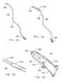
- FIG. 13is a side elevation of a threaded dilator
- FIG. 14is a side elevation of a threaded occluder
- FIG. 15is a side elevation of another variation of a threaded occluder
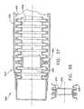
- FIG. 16is a perspective view of a threaded stent, dashed lines showing an internal sidewall reinforcement member and a bushing with a hexagonal drive socket;
- FIG. 17is a cross-sectional view of the stent of FIG. 16 ;
- FIG. 18is a proximal end view of the stent of FIG. 16 , with the hexagonal drive socket visible at the center;
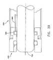
- FIG. 19is a perspective view of a stylet, with a grip on the proximal end and a hexagonal drive tip on the distal end;
- FIG. 20is a perspective view of the hexagonal drive tip of the stylet of FIG. 19 ;
- FIG. 21is a perspective view of a stent-follower with a helical element at the distal end
- FIG. 22is an enlarged, cross-sectional view of the distal end of the stent-follower of FIG. 21 , showing the hidden portion of the bushing, with the hexagonal drive aperture in dashed lines;
- FIG. 23is a cross-sectional view of an intraurethral catheter with flow control, showing the coiled wall reinforcement member acting as a spring on the ball of the check valve;
- FIG. 24is an enlarged perspective view of a stylet tip for operating the check valve of the intraurethral catheter of FIG. 23 ;
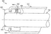
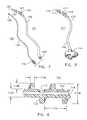
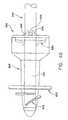
- FIG. 25is a diagrammatic illustration of a suprapubic catheter emplaced through the abdomen, with the distal end anchored by the helical thread in the bladder wall;
- FIG. 26is a partial side perspective view of the helical thread of the suprapubic catheter of FIG. 25 , anchored by the helical thread in a hole in the bladder wall;
- FIG. 27is a partial front perspective view of the suprapubic catheter of FIGS. 25 and 26 anchored in a hole in the bladder wall, the hole being stretched and deformed to fit tightly about the tube and thread of the catheter;
- FIG. 28is a diagrammatic view of a trocar, cannula and guide wire used to install the suprapubic catheter of FIG. 25 ;
- FIG. 29is a distal end view of the suprapubic catheter of FIG. 21 , showing rotational orientation markers;
- FIG. 30is a front perspective diagram of a threaded camera introducer catheter advanced into the transverse colon area
- FIG. 31Ais a partial side view of the distal end of the catheter of FIG. 30 , showing the larger thread height of the thread in the distal area of the catheter's length;
- FIG. 31Bis a partial side view of the mid-section of the catheter of FIG. 30 , showing the reduced thread height of the thread in other than the distal area of the catheter's length;
- FIG. 32is a perspective view of a camera assembly with a video camera or visual sensor head attached to a flexible torque tube or assembly within which run electrical cables and/or light bundles;
- FIG. 33is a partial cross-sectional view of the distal end of the preferred embodiment of FIG. 31A , with the camera assembly of FIG. 32 installed as it would be used;
- FIG. 34is a rotating container and dispensing device by which the catheter of FIG. 30 may be managed and administered during application to a patient;
- FIGS. 35-39are schematic views showing various constructions for a camera introducer with rotary coupling
- FIG. 40is a schematic view of a conduit fitting formed in accordance with the present invention.
- FIGS. 41-43are schematic views of an access device formed in accordance with the present invention.
- a rotate-to-advance structure and methodologyapplicable to a range of medical devices that have heretofore relied entirely or substantially on a push-to-advance technique for penetration of bodily passages.
- Such devicesinclude catheters, dilators, and occluders for mammalian genitourinary or gastrointestinal passages such as the urethra or ureter for the usual purposes associated with such devices where no incising or rupture of passage walls or membranes is intended.
- a threaded catheter 101 for malesis made up of a tube 102 with an external thread 103 , attachable to a flow control device 104 .
- Tube 102is extruded from a polyurethane material, has an inside diameter of 0.06 inches, an outside diameter 103 d of 0.125 inches, and is approximately 13 inches long.
- the durometer, as measured on the smooth, outside wall of the tube,is 85 Shore A.
- Distal end 105is closed off, with its tip rounded to a uniform radius of about 0.06 inches.
- Proximal end 106 of tube 102is cut off square and attached to flow control device 104 .
- Tube 102is sufficiently strong such that when the majority of its length is contained within the urethra, it will withstand and transmit torque, as applied by finger force at the lower end of the tube external of the urethra, to the thread.
- external thread 103is formed from a strip of polyurethane material with a rectangular cross-section of width 103 a , 0.05 inches, and height 103 b , 0.032 inches, and continuously attached over its length to tube 102 , starting 0.2 inches from distal end 105 and extending four complete turns around tube 102 in a clockwise direction towards proximal end 106 at a uniform pitch 103 c of 0.25 inches, resulting in a four-turn thread or helix about one inch long.
- the thread height 103 b of catheter 101is greater than twenty percent (20%) of the 103 d thread diameter. This relative height is desirable to expand and penetrate the longitudinal folds of the urethra to a sufficient depth to achieve a useful grip by the thread.
- the diameter of the helix formed by thread 103 of catheter 101is referred to as thread diameter 103 d , and is equal to two thread heights 103 b plus the outside diameter 102 d of catheter tube 102 or, in this case, 2 times 0.032 inches plus 0.125 inches, or approximately 0.19 inches.
- the circumference C of the helix formed by thread 30is calculated as H (pi) times thread diameter 103 d or, in this case, 3.14 times 0.19, or approximately 0.6 inches.
- C⁇ thread diameter 103 d
- the ratio R of thread pitch 103 c , 0.25 inches, to the circumference of thread diameter 103 d , at 0.6 inches,is much less than 1 to 1, thereby improving the leverage of the screw thread for converting rotation into longitudinal pulling power, as compared to ratios larger than 1/1.
- thread 103has a radius of 0.015 inches.
- thread 103may be attached to tube 102 by wicking tetrahydrofuran (THF) solvent under the thread using a fine hollow tube.
- Catheter 101may be molded in large quantities with thread 103 being an integral part of the molded structure.
- two drainage ports 107connecting to lumen 108 , are oval in shape, the major axis of the oval being parallel to the axis of tube 102 and about 1.5 times the minor axis, which is about equal to the diameter of the lumen.
- the two portsare configured 180 degrees apart radially, and spaced longitudinally to fit between the turns of thread 103 .
- Both ends of thread 103are tapered from zero to full height in one-half turn of the helix, to facilitate gentle, gradual displacement of urethra wall 2 by thread 103 when catheter 101 is rotated clockwise for advancement into the urethra and counterclockwise for retraction.
- the difference between thread height 103 b and pitch 103 c shown in FIG. 3is sufficient that the urethra wall 2 does not bridge between adjacent turns of thread 103 , but rather is only displaced in a manner closely conforming to the cross-section of thread 103 , thereby providing the longitudinal grip on urethra wall 2 for advancing and retracting the catheter.
- catheter 101is shown in proper position for draining bladder 4 , after it has been advanced through the urethra 6 until the helix passes out of the urethra into the bladder.
- thread 103must be limited in length to be advanced to any point above the sphincter 8 , so that the sphincter may contract directly onto the smooth, round, exterior of tube 102 , thereby preventing leakage around the tube, and further constraining catheter 101 from migrating or being forced out of the urethra by pressure from urine in the bladder. It is further apparent from the anatomy shown in FIG. 1 that there is a limit to the length of thread 103 on a catheter that can be advanced to a position above the sphincter 8 , not more than about six turns within the optimal range of thread pitch, and still fit within the bladder 4 without interference. A limited length of thread 103 also localizes the area of pulling force to the upper end of catheter 101 , thereby assuring that the trailing length of the catheter is drawn, not pushed, through the passage.
- a useful alternative embodiment of catheter 101incorporates the recited external thread 103 for rotational advancement, but provides for the central lumen to connect to or terminate in a straight-through or axially-aligned drainage port at the distal tip of the catheter, similar to the most basic conventional catheters. This is likewise useful for drainage and also enables the insertion or passage of guidewires or other devices where specific procedures require it.
- a threaded catheter 111 for femalesis made up of a tube 112 with a thread 113 , attachable to a flow control device 114 .
- Tube 112is extruded from polyurethane material, has an inside diameter of 0.063 inches, an outside diameter 112 d of 0.125 inches, and is approximately seven inches long.
- the durometer, as measured on the smooth, outside wall of the tube,is 85 Shore A.
- Distal end 115is closed off, with its tip rounded to a uniform radius of about 0.06 inches.
- Proximal end 116 of tube 112is cut off square and attached to flow control device 114 .
- Tube 112is sufficiently strong such that when the majority of its length is contained within the urethra, it will withstand and transmit torque, as applied by finger force at the lower end of the tube external of the urethra, to the thread or helix.
- thread 113 of catheter 111is formed from a strip of polyurethane material with a rectangular cross-section of width 113 a of 0.05 inches and height 113 b of 0.10 inches, attached to tube 112 starting 0.2 inches from distal end 115 and extending four turns around tube 112 in a clockwise direction towards proximal end 116 at a uniform pitch 113 c of 0.25 inches, resulting in a four-turn thread or helix about one inch long.
- the thread height 113 b of catheter 111is much greater than twenty percent (20%) of tube diameter 112 d , at 0.125 inches. This relative thread height is desirable in order to expand and penetrate the longitudinal folds of the female urethra sufficiently far to achieve a useful grip by the thread.
- the diameter 113 d of the helix formed by thread 113is equal to two thread heights 113 b plus the diameter 112 d or, in this case, 2 times 0.10 plus 0.125, or approximately 0.33 inches.
- the circumference C of the helix formed by thread 113is calculated as ⁇ (pi) times the thread diameter 113 d or, in this case, 3.14 times 0.33, or approximately 1.0 inches.
- the ratio R of thread pitch 113 cat 0.25 inches, to the circumference C, at 1.0 inches, is again much less than 1 to 1, thereby improving the leverage of the thread for converting rotation into longitudinal pulling power as compared to larger ratios.
- Catheter 111may be constructed or fabricated by the same means as catheter 101 .
- two side drainage ports 117connecting to lumen 118 , are oval in shape, the major axis of the oval being parallel to the axis of tube 112 and about 1.5 times the minor axis, which is about equal to the diameter of the lumen.
- the two side ports 117are configured 180 degrees apart radially, and spaced longitudinally to fit between the turns of the thread.
- the ends of thread 113are tapered from zero to full height in three-quarters turn of the helix, to facilitate gentle, gradual displacement of the urethra wall by the thread when the catheter is rotated clockwise for advancement and counterclockwise for retraction.
- the difference between width 113 a and pitch 113 cis sufficient that the urethra wall does not bridge between adjacent turns, but rather is displaced in a manner closely conforming to the profile of the thread, thereby providing the longitudinal grip on the urethra wall for advancing and retracting the catheter, in the same manner as the thread of catheter 101 of FIGS. 2 and 3 .
- the optimal position for threaded catheter 111 for draining the bladder of a female subjectis where it is advanced through the urethra until the thread passes out of the urethra into the bladder, similar to how catheter 101 is illustrated in FIG. 1 , but for females.
- the userassembles materials including a sterile threaded catheter 101 or 111 , a container for urine, soap and water, a water soluble lubricant (if the catheter is not pre-lubricated), a mirror (for females), and tissues.
- the userwill then wash the hands and urethral opening with soap and water, squeeze out a small amount of lubricant into clean tissue, dip the distal end tip of the catheter into the lubricant, and manually engage the tip of the catheter into the urethral opening (the mirror may be helpful for females to assist in locating the opening).
- the userwill then gently push and turn the catheter in, far enough to engage the thread about one full turn with the urethra, and then gently rotate the tube of the catheter in the direction of the thread, preferably clockwise, to advance the catheter into the urethra until urine appears in the tube.
- the userthen pauses to drain the bladder, directing the urine into the container, then resumes rotation of the catheter until it is no longer advanced by the rotation, indicating that the thread of the catheter has passed into the bladder and the catheter is in proper position.
- the catheteris removed when appropriate using similar precautions for cleanliness and containment, by rotating the catheter in a direction opposite the direction of insertion, presumably counterclockwise.
- a catheter 121which is made up of tube 122 with thread 123 applied in the form of a helix, and utilizing a flexible shaft stylet 131 as an insertion and retraction tool.
- Stylet 131has a grip 133 at its proximal end for turning the device.
- Tube 122is configured with non-rotational fitment 124 ( FIG.
- stylet 131can be inserted through the tube's proximal end 126 , passed up through lumen 128 of tube 122 , and the tip 134 of stylet 131 engaged with fitment 124 in a manner that allows rotation of grip 133 in one direction to rotate catheter 121 for advancement into the urethra, and in the other direction for retraction.
- the flexible shaft 132 of stylet 131is sufficiently strong such that when it is fully inserted into catheter 121 , shaft 132 will withstand and transmit torque, as applied by finger force to knurled knob grip 133 external of the urethra, to the thread 123 .
- Stylet 131is removed after catheter 121 is installed, and reinserted for retracting the catheter when required.
- Fitment 124is an elongated collar with a multi-faceted interior wall, securely anchored within tube 122 , and configured to receive, in a non-rotational relationship, tip 134 .
- Tip 134is configured with a corresponding elongated, multi-faceted exterior shape and rounded end, to readily enter fitment 124 .
- Stylet tip 134 and fitment 124can be alternatively configured and connected by various means to provide a non-sliding, as well as non-rotational, connection.
- a threaded Foley-type catheter 141 of the inventionis made from polyurethane material.
- Catheter 141comprises a flexible tube 142 with an axial drainage lumen 148 running from a drainage port 149 to its proximal end 146 a , and a thread 143 applied to its external surface near its distal end 145 in the manner of the threaded catheters previously described.
- Catheter 141has a thin-walled inflatable elastic balloon 150 encasing the helical thread 143 and sealed to tube 142 above and below (i.e., distal and proximal to) the thread 143 . Drainage port 149 is located above (or distally) from balloon 150 .
- a smaller inflation lumen 151 within tube 142communicates between inflation port 152 (within the envelope of balloon 150 ) and the distal end 146 b of the catheter. Lumens 148 and 151 are isolated from each other, as indicated by FIGS. 11 and 12 .
- Balloon 150when uninflated, is normally contracted tightly about helical element 143 as illustrated in FIG. 12 , and may be inflated as in FIG. 10 by injecting fluid through lumen 151 and into the balloon cavity 153 .
- the flexible tube 142is of sufficient torsional strength to withstand and transmit rotational finger force, applied at the proximal end of tube 142 , to thread 143 .
- a dilator 201 and occluders 211 and 221are similarly constructed by configuring the upper end 205 of a flexible shaft 202 with a tapered bulb 204 near its distal end, and disposing thereon one or two sections of thread 203 .
- These threadsare similar to thread 103 on catheter 101 of FIGS. 2 and 3 , wherein the height of the thread is at least twenty percent (20%) of the diameter of the shaft 202 , and the ratio of thread pitch to the circumference of the thread diameter at any given point on the bulb or shaft is less than one to one (1/1).
- the ends of threads 203are tapered for ease of advancing and retracting, again similar to the threaded catheter of FIGS. 2 and 3 .
- Dilator 201of FIG. 13 , is configured with multiple turns of thread 203 extending over both ends of tapered bulb 204 , and is used to dilate a constricted passage by being rotatingly advanced and retracted through the obstructed area of the passage in the same fashion as the threaded catheters of the invention.
- Occluder 211of FIG. 14 , is configured with two sections of thread 203 , leaving the midsection or bulbous portion of tapered bulb 204 smooth and round in order to provide a uniform occluding surface.
- This occluderis used to plug or constrict a passageway at an interior point, being rotatingly advanced to and retracted from that point in the same fashion as the threaded catheters of the invention.
- Occluder 221of FIG. 15 , is configured with two sections of thread 203 , the lower or proximal end thread 203 being disposed on the shaft 202 below the tapered bulb 204 , leaving the lower tapered end of bulb 204 smooth and round in order to provide a uniform occluding surface.
- This occluderis used to plug a passageway at the interior end neck or entrance, being rotatingly advanced until the tapered bulb passes entirely through the passage while the lower thread remains engaged in the passage, and being then rotatingly retracted to seat the tapered bulb against the neck of the passage. The occluder is then rotatingly retracted when appropriate.
- a threaded urethral stent 301 made from polyurethane materialhas a tube 302 with an external thread 303 of uniform pitch.
- Thread 303is similar to thread 103 of catheter 101 of FIGS. 2 and 3 , wherein the height of the thread is at least twenty percent (20%) of the diameter of the shaft 202 , and the ratio of thread pitch to the circumference of the thread diameter is less than one to one (1/1).
- the ends of thread 303are tapered for ease of advancing and retracting through a passage.
- Bushing 304has a tapered interior wall 308 extending from the bushing's full diameter at one end to a uniform hexagonal aperture 309 .
- Coiled sidewall reinforcement member 310is secured within stent 301 intermediate bushing 307 and interior shoulder 304 .
- Alternative embodimentsmay have a section of the thread being tapered to a lesser height or no height, so as to provide a “waist” for gripping by a muscular zone such as the prostate or sphincter.
- reinforcement member 310could be configured or molded into the sidewall of tube 302 .
- a stylet 331similar to the stylet 131 of FIG. 7 , has a flexible shaft 332 with a grip 333 at the proximal end for turning, and a hardened hexagonal tip 334 at the distal end which closely fits into aperture 309 of stent 301 in a non-rotational manner for emplacement of the stent by the method of the invention.
- the flexible shaft 332 of the styletis sufficiently strong such that when tip 334 is inserted into aperture 309 , the shaft will withstand and transmit torque, as applied by rotational finger force at grip 333 , to thread 303 .
- a threaded stent-follower 341has a flexible tube 342 , the lumen 347 ( FIG. 22 ) of which is sized to accept the ready insertion of tip 334 and shaft 332 of stylet 331 of FIG. 19 .
- Tube 342is of sufficient torsional strength to accept and transmit rotational finger force applied at its proximal end 346 to its distal end 345 .
- a thread 343 of uniform pitch, and not more than six turns,is applied to the external surface of tube 342 near distal end 345 .
- Thread 343preferably conforms to the same twenty percent (20%) “rule” of thread height to tube diameter, and the ratio of thread pitch to thread circumference of less than one to one (1/1), as thread 103 in FIGS. 2 and 3 as described above.
- the ends of thread 343are tapered for ease of advancing and retracting.
- bushing 351( FIG. 22 ) has a uniform hexagonal aperture 352 which is the same size as aperture 309 in bushing 307 of stent 301 , and a tapered interior wall 353 extended from its full diameter at its proximal end to aperture 352 .
- Bushing 351also has an external tapered tip 354 at its distal end.
- Bushing 351is affixed within the distal end 345 of tube 342 , with tip 354 protruding, such that the distal end 345 of stent-follower 341 mates with a self-centering action with the proximal end of stent 301 when the two devices are brought into contact with approximate axial alignment.
- tip 334 ( FIG. 19 ) of stylet 331may be extended through aperture 352 ( FIG. 22 ) and into aperture 309 ( FIG. 17 ), thereby locking stent 301 and stent-follower 341 into a fixed rotational relationship.
- the rotation of the proximal end of stylet 331 and stent-follower 341causes the concurrent rotation of stent 301 , whether to rotatingly advance or retract the stent.
- Stylet 331may be withdrawn and stent-follower 341 rotatingly retracted, leaving stent 301 positioned at any useful point within a passageway.
- threaded intraurethral catheter 361incorporates means for flow control.
- the catheterhas a tube 362 made from a section of extruded polyurethane tubing material, with thread 363 of uniform pitch and not more than six turns applied to its external surface.
- Thread 363preferably conforms to the same twenty percent (20%) “rule” of thread height to tube diameter, and ratio of thread pitch to thread circumference of less than one to one (1/1), as thread 103 in FIGS. 2 and 3 as described above.
- Alternative embodimentsmay have a section of the thread being tapered to a lesser height or no height, to provide a “waist” for gripping by a muscular zone such as the prostate or sphincter.
- a portion of reinforcement member 370could be configured or molded into the side wall of tube 362 .
- Bushing 367has a tapered interior wall 368 extending from the bushing's full diameter at one end to a uniform hexagonal aperture 369 .
- a coiled sidewall reinforcement member 370 and a check ball 371are secured between interior shoulder 364 and bushing 367 so that coiled member 370 holds ball 371 in compression against the upper (proximal) end of bushing 367 in the manner of a check valve, whereby to prevent outward (proximal) flow through the lumen 372 of the stent.
- Coiled member 370may be compressed by upward movement of ball 371 , thereby opening the check valve to flow.
- alternate hexagonal tip 384 for stylet 331has a slightly concave proximal end 385 and flutes 386 .
- tip 384When used in conjunction with stent-follower 341 to actuate the check valve of catheter 361 , tip 384 is adapted to be inserted through aperture 369 of catheter 361 to push ball 371 upward against coil member 370 , thereby opening the check valve function and permitting outward flow of fluid through flutes 386 and aperture 369 and then into and through stent-follower 341 .
- the threaded suprapubic catheter 401 of FIGS. 25 and 26is constructed with a flexible tube 402 , with a lumen 408 connecting axial ports at the proximal end and the distal end, and an external thread 403 of uniform pitch applied at its distal end.
- the ratio of thread pitch 403 c to the circumference of thread diameter 403 dis much less than one to one (1/1).
- Tube 402is of sufficient torsional strength to accept and transmit rotational finger force, applied at the proximal end, to the distal end.
- the ends of thread 403are tapered for ease of advancing and retracting the catheter through the abdomen and into the bladder wall.
- relative thread height 403 bis greater than in the case of catheter 101 of FIGS. 2 and 3 ; preferably greater than fifty percent (50%). This is because suprapubic catheter 401 is being advanced by the rotation of thread 403 along an unlined path through the abdomen, and being anchored against longitudinal displacement by the engagement of pitch 403 c of thread 403 in a hole pierced into the wall of organ 31 that must encompass tube 402 plus thread 403 passing through the plane of the organ wall 31 . This is distinguished from the longer gripping surface available in a lined passageway as is the case for the catheter 101 of FIG. 4 .
- the method by which suprapubic catheter 401 is deployedis conventional to the extent that trocar 421 and cannula 422 are used with ultrasound or fluoroscopy to create the path through abdomen wall 21 into the bladder organ 31 ; trocar 421 is removed and temporary guidewire 423 is then inserted through cannula 422 , extending from outside the abdomen wall 21 to inside the bladder organ 31 . Cannula 422 is then withdrawn, leaving guidewire 423 as a connecting path, extending from outside the body, passing through the abdominal wall 21 , and into the bladder organ 31 .
- Suprapubic catheter 401is then threaded over the proximal end of guidewire 423 , and gently started into the abdomen wall 21 with a rotating motion of about one turn until thread 403 is firmly engaged.
- the catheteris then rotatingly advanced along the guidewire through the unlined pathway in the same manner as other threaded devices of the invention, until thread 403 penetrates the wall of organ 31 about one full turn, as determined by ultrasound, fluoroscopy or equivalent means.
- the distal end of catheter 401is then secured in a non-rotatable fashion to abdomen wall 21 using conventional adhesive means or equivalent means, thereby locking thread 403 at the distal end of the catheter in position in the wall of organ 31 .
- Guidewire 423is then withdrawn. Threaded suprapubic catheter 401 is then available for use.
- radiopaque markers 411embedded at select points displaced along the perimeter of thread 403 , provide the capability for external detection and monitoring (through fluoroscopy or other means) of the orientation and movement of the distal end of the catheter.
- threaded camera introducer catheter 500suitable for an average size adult's colon, consists of a bulbous tip 501 connecting to a soft, flexible tube 502 which is about 5 feet long with a tube diameter 502 d of 1 inch.
- Lumen 508extends from the interior face of a window 511 on the distal end of tip 501 , through tip 501 and tube 502 to the proximal end of tube 502 .
- external thread 503with uniform pitch 502 c of 1 inch, begins at the edge of window 511 , tapering from nothing to a height of about 0.16 inches, extending around tip 501 and tapering there to about 0.32 inches, and continuing proximally for about 6 inches along tube 502 .
- thread heightthen tapers from a thread height of 0.32 inches down to 0.16 inches and continues at this height to the proximal end of tube 502 .
- introducer 500may have a relatively diminutive tip, but maintain an external thread of equal or greater height and total circumference.
- Another variation of introducer 500may have thread 503 applied only to the introducer's distal end, the thread terminating after a few turns, analogous to catheter 101 of FIG. 2 .
- the 0.32 inch thread height of thread 503 spanning about 6 inches at the distal end of camera introducer 500is greater than twenty percent (20%) of tube diameter 502 d .
- a relative thread height in the range of 20 percent or more of the camera introducer diameter size, appropriate to the subject's size,is desirable to expand and penetrate the walls of the colon to a sufficient depth to achieve a useful grip by the thread in accordance with the rotate-to-advance technology of the invention.
- the relatively lower thread height of the continuing threadis adequate to assist in the rotational advancement of the fill length of the device without exerting undue forward pressure on the distal end. It also aids in the easing of advancement over the full length of the introducer around and through the bends in the colon.
- the thread pitch 503 cis much less than the overall circumference of thread 503 , thereby providing the necessary leverage to translate rotational effort at the proximal end to a forward force greater than the friction against the wall of the colon.
- Simple vector analysisconfirms this result.
- a camera assembly 520consists of camera 521 , with light lens 522 and image lens 523 , attached to a flexible, hollow, jointed spine 531 .
- a cable harness 541connected to camera 521 , passes through spine 531 , extending out the proximal end and connecting to the necessary power, control and display equipment.
- Spine 531is constructed of a chain of vertebrae 532 , connected by universal joints which combine flexibility with torsional strength.
- camera assembly 520is shown installed in camera introducer catheter 501 , with camera 521 secured within tip 501 by set screw 512 , so that the camera views forward through the window.
- the camera assembly and catheterare combined here as a camera introducer system.
- rotating container and dispensing system 550consists of drum 551 with axial opening 552 around which handle 553 is rotatably attached.
- Catheter 501is rotatingly dispensed during application by holding handle 553 and rotating drum 551 while catheter 501 is being rotatingly advanced in the subject colon.
- FIGS. 30-34there is shown a threaded camera introducer catheter 500 which may be used to position a camera assembly 520 within a body passageway.
- the camera assembly's umbilage connectionse.g., light, electrical, fluid, etc.
- water connections to the distal end of the endoscopemust be designed to rotate freely about the axis of the endoscope, with a leak-proof seal, etc. Again, this can add significant cost and complexity to an already costly and complex endoscope system.
- a new threaded camera introducer catheterwhich has a rotary coupling at its distal end which is free to rotate relative to the body of the introducer.
- This new camera introducer catheteris installed over the distal end the endoscope, with the distal end of the endoscope being secured to the rotary coupling. Due to the fact that the endoscope is attached to the camera introducer catheter by means of the rotary coupling, the camera introducer catheter is free to rotate about its axis while the endoscope remains rotationally stationary.
- This new arrangementallows the camera introducer catheter to rotate about its longitudinal axis, whereby to advance the introducer (and hence the endoscope) within the colon; at the same time, however, inasmuch as rotation of the camera introducer catheter is not transferred to the endoscope, the endoscope (and hence all of its associated input and output connections) remains rotationally stationary.
- the new camera introducer catheterallows the medical practitioner to hold the proximal end of the endoscope in the customary manner, i.e., rotationally fixed, yet to deploy the endoscope using the rotate-to-advance methodology of the present invention. This is a significant advance in the art.
- FIGS. 35 and 36there is shown a threaded camera introducer catheter 600 which may be used to position a camera assembly or endoscope 700 within the colon.
- camera introducer catheter 600is preferably substantially the same as the camera introducer catheter 500 described above, except for the provision and use of the rotary coupling 605 which will hereinafter be discussed in further detail. More particularly, camera introducer catheter 600 generally comprises a tube 610 upon which is formed a helical thread 615 . Tube 610 has sufficient rigidity that rotation applied to the proximal end of the tube will be transmitted to the distal end of the tube; at the same time, tube 610 also has sufficient flexibility that the tube may bend around curves in the colon.
- helical thread 615has a geometry such that when the camera introducer catheter 600 is positioned within the colon, rotation of the proximal end of the catheter will cause helical thread 615 to pull the camera introducer catheter 600 along the colon, in the rotate-to-advance fashion of the present invention.
- camera introducer catheter 600includes the rotary coupling 605 .
- Rotary coupling 605is rotatably attached to the distal end of tube 610 , such that the rotary coupling may rotate freely about the axis of the tube while being fixed, longitudinally, to the tube.
- camera introducer catheter 600is constructed so as to minimize friction between rotary coupling 605 and tube 610 when tube 610 is rotated.
- low friction bushings or bearingsmay be used, and/or appropriate lubricants and/or coatings may be applied to contacting surfaces.
- the joinder between rotary coupling 605 and tube 610may be sealed to prevent fluid infiltration.
- a design addressing this featuremay include labyrinth, point-contact and wiper configurations. See, for example, FIG. 36 , where a pair of O-ring seals 620 and 625 seal the construction against fluid penetration.
- the camera assembly or endoscope 700is intended to be secured to rotary coupling 605 so that the endoscope will be longitudinally fixed to camera introducer catheter 600 but free to rotate relative to the camera introducer catheter.
- camera assembly or endoscope 700may be mounted to rotary coupling 605 by means of a set screw 630 which causes a protective ring liner 635 into binding engagement with endoscope 700 .
- Access to set screw 630may be through an opening 640 in tube 610 .
- camera assembly or endoscope 700may be secured to rotary coupling 605 of camera introducer catheter 600 whereby, when the camera introducer catheter 600 is thereafter placed within the colon and the proximal end of the catheter's tube 610 is rotated, the distal end of tube 610 will turn, whereby helical thread 615 will pull the catheter (and hence endoscope 700 ) distally along the colon.
- endoscope 700will remain rotationally stationary with respect to the rotating catheter.
- endoscope 700may be advanced within the colon using the rotate-to-advance technique of the present invention, without requiring any corresponding rotation of the endoscope itself.
- the medical practitionerwill be able to maintain effective visualization of the colon as the endoscope is advanced within the colon.
- the endoscope's umbilage connectione.g., light, electrical, fluid, etc.
- threaded camera introducer catheter 600may be provided with multiple rotary couplings, with the additional rotary couplings being positioned anywhere along the length of catheter 600 .
- a relatively short introducer catheter 600might utilize a pair of rotary couplings, one (i.e., 605 ) at the distal end of the catheter and one (i.e., 605 A) at the proximal end of the catheter;
- a longer introducer catheter 600might include several additional rotary couplings, with the additional rotary couplings (i.e., 605 B) being disposed between the two end rotary couplings.
- threaded introducer catheter 600may include design features designed to maximize the tortional stiffness of its tube 610 while minimizing bending stiffness of the tube.
- tube 610may be formed with a composite construction comprising an inner convoluted or corrugated tube 645 , a braided fiber layer 650 and a flexible outside layer 655 .
- one or more low friction bearings 660may be positioned within the catheter's interior lumen so as to reduce surface contact with the endoscope (not shown in FIG.
- bearings 660include a protrusion 665 which is adapted to ride in the helical trough of the convoluted or corrugated tube 645 .
- bearings 670may be provided, where bearings 670 include a recess 675 for receiving the helical peak of convoluted corrugated tube 645 .
- the threaded camera introducer catheter 600may also include a feature to disconnect the rotary coupling 605 from the endoscope while the catheter 600 is deployed within the body. This disconnect may be effected via fluid, mechanical, electrical or other means. See, for example, FIG. 39 , where a fluid line 680 is used to expand and deflate a bladder 685 so as to selectively bind and release, respectively, the endoscope 700 to and from rotary coupling 605 .
- threaded introducer catheter 600may be used to deploy objects other than an endoscope 700 .
- introducer catheter 600may be used to deploy other visualization apparatus (e.g., ultrasound devices) and other objects which have umbilage associated therewith, e.g., a fluid dispenser apparatus, a vacuum snare, surgical instruments, etc.
- novel apparatus for effecting Brachytherapythat is, for directing radioactive material to a target site within the body, while allowing for easy implantation and removal.
- Such novel Brachytherapy apparatusmay be cannulated or non-cannulated, depending on the anatomy which is to be targeted.
- the devicemay be used for the treatment of prostate cancer where the radioactive material must be delivered to the region of the affected prostate gland.
- the radioactive materialmust be delivered to the region of the affected prostate gland.
- itwill generally be desirable to use a cannulated form of the invention.
- the novel Brachytherapy apparatusmay comprise a stent such as the stent 301 shown in FIGS. 16-18 , along with its associated threaded stent-follower 341 shown in FIGS. 21 and 22 , as well as its associated stylet 331 shown in FIGS. 19 and 20 , except that the stent includes radioactive materials RM ( FIG. 17 ) incorporated into its construction.
- the Brachytherapy stent 301when Brachytherapy stent 301 is emplaced within the urethra adjacent to the target prostate tumor, the Brachytherapy stent may irradiate the tumor so as to effect the desired Brachytherapy.
- the devicein another preferred application of the novel Brachytherapy apparatus, may be used for the treatment of breast cancer, where the therapeutic radiation must be delivered to the breast.
- the devicemay be desirable to use a non-cannulated form of the invention.
- the novel Brachytherapy apparatusmay comprise a threaded solid element such as the dilator 201 shown in FIG. 13 , except that the dilator may include radioactive materials RM ( FIG. 13 ) incorporated into its construction.
- the Brachytherapy dilator 201when Brachytherapy dilator 201 is advanced through a mammary canal (accessed through an opening on the nipple) and into the interior of the breast, whereby it may reside adjacent to a target tumor, the Brachytherapy dilator may irradiate the tumor.
- the radioactive materials RM of the aforementioned Brachytherapy stent 301 and/or the aforementioned Brachytherapy dilator 201may be replaced by a therapeutic agent capable of leaching out of the wall of the delivery device and thereby be delivered to the target tumor. Additionally, the therapeutic agent may be coated onto a wall of the delivery device for delivery to the target region.
- FIG. 40there is shown a conduit fitting 800 which can be used to provide a quick and effective access to a corporeal conduit such as an artery or vein, etc.
- Conduit fitting 800generally comprises a body 805 and an obturator 810 .
- Body 805has a helical thread 815 formed on its distal end, and an enlarged flange 820 formed on body 805 proximal to helical thread 815 .
- a central lumen 825extends the length of body 805 .
- a fluid valve 830preferably in the form of one or more deformable seals, is disposed at the distal end of the device so as to selectively close off lumen 825 .
- Obturator 810is sized to fit within, and close off, lumen 825 of body 805 .
- obturator 810is adapted to drivingly engage body 805 , whereby rotation of obturator 810 may be converted into corresponding rotation of body 805 .
- obturator 810may be drivingly connected to body 805 by an obturator pin 835 which engages a pair of body ears 840 .
- a small holeis first made into a corporeal conduit, e.g., a blood vessel.
- a corporeal conduite.g., a blood vessel.
- the distal end of body 805with obturator 810 in place, is then inserted into the hole.
- obturator 810is turned so as to cause body 805 to turn, whereupon thread 815 will pull the distal end of body 805 into the interior of the blood vessel.
- Engagement of flange 820 with the outer surface of the blood vesselwill prevent further movement of body 805 into the blood vessel.
- Engagement of flange 820can also assist in sealing the blood vessel against leakage.
- flange 820may comprise a compliant seal and/or may comprise a thrombogenic agent.
- Obturator 810may then be removed; however, blood will not pass out of the proximal end of body 805 due to the presence of fluid valve 830 . Thereafter, when instruments or the like are to be introduced into the blood vessel by means of body 805 , they may be pushed through the fluid valve 830 and lumen 825 .
- body 805may be backed out of the blood vessel, e.g., by reinserting obturator 810 into body 805 so that obturator pin 835 engages body ears 840 , and then appropriately turning the distal end of the obturator so as to unscrew body 805 from the wall of the blood vessel.
- Body 805is preferable absent of perforations so as to minimize any ingrowth of tissue into the body, which may render subsequent removal more difficult. Additionally, various materials and/or coatings may be used to minimize tissue ingrowth to body 805 .
- colonoscopeVisual examination of the large intestine (colonoscopy) is performed by passing a colonoscope, retrograge, the entire length of the intestine, starting at the rectum and advancing to the cecum.
- Standard practiceis to lubricate the colonoscope and the entry site (i.e., the anal sphincter) prior to inserting the colonoscope with a combination of push-and-quarter turn twisting motion.
- Access device 900comprises two main elements, a liner 905 having a central lumen 907 and an obturator 910 sized to selectively close off lumen 907 .
- obturator 910is first positioned in lumen 907 of liner 905 , and then the assembly is inserted into the rectum. Once access device 900 is inserted in the rectum, obturator 910 is removed, thereby providing a tubular access into the rectum. Then the colonoscope (with associated threaded introducer catheter 500 if desired) can be passed freely into the rectum.
- Liner 905may or may not have a helical thread or other surface geometry on the exterior of the tube to help advance the liner into the rectum or to help keep it in place. Additionally, liner 905 may be designed with a feature to cause it to split so it can be easily removed from the procedure site once the colonoscope has entered the rectum.
Landscapes
- Health & Medical Sciences (AREA)
- Life Sciences & Earth Sciences (AREA)
- Surgery (AREA)
- Engineering & Computer Science (AREA)
- General Health & Medical Sciences (AREA)
- Veterinary Medicine (AREA)
- Public Health (AREA)
- Animal Behavior & Ethology (AREA)
- Heart & Thoracic Surgery (AREA)
- Biophysics (AREA)
- Biomedical Technology (AREA)
- Nuclear Medicine, Radiotherapy & Molecular Imaging (AREA)
- Medical Informatics (AREA)
- Molecular Biology (AREA)
- Radiology & Medical Imaging (AREA)
- Physics & Mathematics (AREA)
- Pathology (AREA)
- Optics & Photonics (AREA)
- Pulmonology (AREA)
- Anesthesiology (AREA)
- Hematology (AREA)
- Mechanical Engineering (AREA)
- Media Introduction/Drainage Providing Device (AREA)
Abstract
Description
- 1. a channel opening for suction and passage of accessories;
- 2. a light guide lens to distribute light from a fiberoptic bundle to illuminate the visual field;
- 3. an objective lens to focus an image of the mucosa onto the face of an image bundle for transmission back to an eyepiece; and
- 4. an air/water jet, which supplies air to inflate the organ being observed, and water to clean off the image (i.e., objective) lens.
- a. the cecum;
- b. the ascending colon, which runs cephalad (towards the head) from the cecum to the hepatic flexure;
- c. the transverse colon, which runs from the hepatic flexure in the upper quadrant to the splenic flexure in the left upper quadrant;
- d. the descending colon, which runs caudad (toward the feet) from the splenic flexure to the left lower quadrant;
- e. the sigmoid colon, which runs from the left lower quadrant to the rectosigmoid junction; and
- f. the rectum, which extends down to the anal canal.
- 1. The helical thread or spiral extending the length of the device may be used for auxiliary purposes, including to:
- a) carry fluids into the colon/passage;
- b) provide vacuum to the passageway itself, or vacuum within the device to facilitate the advancement of the camera or endoscope into the device;
- c) convey light bundles or electrical wires for specific purposes, and/or;
- d) provide depth markers to assist the practitioner in determining the general position of the device within the body;
- 2. the spiral may also be inflated with a fluid during entry to obtain full thread form and rotationally grip or fix the catheter to the camera element, and then deflated to permit non-rotational removal by pulling the device through the colon;
- 3. the video screen, or the image on the screen as seen through the rotating camera introducer as it advances, may be electronically processed to hold the image in a non-rotating, stationary manner for the benefit of the person administering the procedure;
- 4. the distal portion of the device may be relatively more flexible to enhance trackability along the path of the colon/passageway;
- 5. the device may have sufficient torque transmission capability from the proximal to the distal end so the distal portion of the device can be thus rotated at full length in the colon without interior support;
- 6. the distal tip or zone may have a sufficient thread height to grip the colon wall and provide the primary “pulling power” to advance the device into the body and negotiate the turns, while the somewhat lower thread height along the remainder of the device is adequate to support rotational advancement without drag and avoid bunching or gathering of the colon wall;
- 7. there are at least three methods of containing and controlling this 160 cm long instrument to ensure it remains within the operating field:
- a) a dispensing device as shown in
FIG. 34 ; - b) a straight tubular component; or
- c) held by an assistant;
- a) a dispensing device as shown in
- 8. material of construction:
- a) the main body may be produced from polyvinylchloride (PVC) plastic and may be reinforced with wire or fabric;
- b) the helix may be made of PVC and may be reinforced with wire or otherwise;
- c) a distal end window may be a flat, optically clear plastic lens made from PVC, polycarbonate, or acrylic plastic;
- 9. alternative uses:
- a) variations on the introducer device within the scope of the invention include full length tubes, or short sections analogous to urethral stents, being emplaced in the colon by the rotational structures and techniques of the invention for temporary purposes such as to aid in the repair of a damaged colon or a related abdominal injury or condition, by providing a supplemental lining and/or form to the colon or to a section of the colon;
- 10. camera with torque control umbilicus:
- a) the camera body which houses both the camera and the light source may be made of stainless steel or molded with a dimensionally stable plastic such as polycarbonate;
- b) the vertebrae which makes up the torque control umbilicus may be made of a high strength thermoplastic or a metal such as stainless steel or beryllium copper.
- 1. The helical thread or spiral extending the length of the device may be used for auxiliary purposes, including to:
- 1. as an “introducer”, it includes the following characteristics and benefits:
- a) it conveys a camera assembly along the entire colon to screen patients for polyps, lesions, cancer sights and other maladies;
- b) the entire colon can be examined without the need for a conventional colonoscope/endoscope;
- c) a total examination of the colon can be successfully performed with significantly less manipulation technique, pain, medication and post procedure recovery time;
- d) it requires less training and has greater success in reaching the cecum;
- e) as a single-use disposable device, it allows the expensive camera with its torque controlled umbilicus to be used repeatedly without danger of sequential infections;
- f) the procedure is less expensive when compared to the cost of cleaning and repairing conventional endoscopes and amortizing the cost of a costly video processing unit;
- g) the procedure can be successfully performed by less-specialized, less-expensive individuals; and
- h) the “introducer” is supplied sterilized and ready for use;
- 2. as a more “conventional style endoscope”—by adapting a conventional endoscope to the structure and method of the invention, the benefits of the invention are coupled with the following conventional functions:
- a) tip articulation;
- b) air and water delivery;
- c) suction of fluids;
- d) illumination of passages;
- e) imaging capability;
- f) drug delivery; and
- g) accessories (e.g., working tools).
- 3. as a “hybrid catheter” having some of the functions and features of the more “conventional style endoscope” and/or the “introducer” built into the device for procedure-specific applications; also, it could be used in conjunction with, or independent of, conventional endoscopic devices and accessories; and
- 4. as a “transporter” or “introducer” to deliver a conventional endoscope to any location of the colon or other passageway—this may occur by:
- a) providing a fluid-tight envelope for the endoscope; and
- b) providing a means for the endoscope to exit the distal end of the “introducer” to perform diagnostic/therapeutic procedures normally done with the endoscope.
- 1. as an “introducer”, it includes the following characteristics and benefits:
C=π×
Claims (3)
Priority Applications (12)
| Application Number | Priority Date | Filing Date | Title |
|---|---|---|---|
| US13/065,469US9220395B2 (en) | 1999-09-27 | 2011-03-22 | Rotate-to-advance catheterization system |
| US13/099,223US8435229B2 (en) | 2006-02-28 | 2011-05-02 | Rotate-to-advance catheterization system |
| EP11778191.4AEP2566564B1 (en) | 2010-05-03 | 2011-05-03 | Rotate-to-advance catheterization system |
| CN201180022578.1ACN102933254B (en) | 2010-05-03 | 2011-05-03 | Rotate-to-advance catheterization system |
| JP2013509188AJP5985468B2 (en) | 2010-05-03 | 2011-05-03 | Rotating advance catheter insertion system |
| PCT/US2011/035038WO2011140118A1 (en) | 2010-05-03 | 2011-05-03 | Rotate-to-advance catheterization system |
| US13/100,098US8574220B2 (en) | 2006-02-28 | 2011-05-03 | Rotate-to-advance catheterization system |
| DK11778191.4TDK2566564T3 (en) | 2010-05-03 | 2011-05-03 | SYSTEM FOR CATERIZATION BY ROTARY INSERT |
| US13/192,281US8500628B2 (en) | 2006-02-28 | 2011-07-27 | Rotate-to-advance catheterization system |
| US13/770,641US8684913B2 (en) | 2006-02-28 | 2013-02-19 | Rotate-to-advance catheterization system |
| US13/770,692US8764640B2 (en) | 2006-02-28 | 2013-02-19 | Rotate-to-advance catheterization system |
| US14/294,869US9907456B2 (en) | 2006-02-28 | 2014-06-03 | Rotate-to-advance catheterization system |
Applications Claiming Priority (5)
| Application Number | Priority Date | Filing Date | Title |
|---|---|---|---|
| US15621899P | 1999-09-27 | 1999-09-27 | |
| US09/448,054US6379334B1 (en) | 1997-02-10 | 1999-11-23 | Rotate advance catheterization system |
| US09/671,048US7048717B1 (en) | 1999-09-27 | 2000-09-27 | Rotate-to-advance catheterization system |
| US11/121,751US7909799B2 (en) | 1999-09-27 | 2005-05-04 | Rotate-to-advance catheterization system |
| US13/065,469US9220395B2 (en) | 1999-09-27 | 2011-03-22 | Rotate-to-advance catheterization system |
Related Parent Applications (2)
| Application Number | Title | Priority Date | Filing Date |
|---|---|---|---|
| US11/121,751ContinuationUS7909799B2 (en) | 1999-09-27 | 2005-05-04 | Rotate-to-advance catheterization system |
| US11/363,990Continuation-In-PartUS8377041B2 (en) | 2005-02-28 | 2006-02-28 | Rotate-to-advance catheterization system |
Related Child Applications (2)
| Application Number | Title | Priority Date | Filing Date |
|---|---|---|---|
| US12/924,807Continuation-In-PartUS8764631B2 (en) | 1997-02-10 | 2010-10-05 | Rotate to advance catheterization system |
| US12/942,807Continuation-In-PartUS8485627B2 (en) | 2009-12-11 | 2010-11-09 | Inkjet recording apparatus and landing-location adjustment method |
Publications (2)
| Publication Number | Publication Date |
|---|---|
| US20120059210A1 US20120059210A1 (en) | 2012-03-08 |
| US9220395B2true US9220395B2 (en) | 2015-12-29 |
Family
ID=38291138
Family Applications (3)
| Application Number | Title | Priority Date | Filing Date |
|---|---|---|---|
| US09/671,048Expired - LifetimeUS7048717B1 (en) | 1999-09-27 | 2000-09-27 | Rotate-to-advance catheterization system |
| US11/121,751Expired - Fee RelatedUS7909799B2 (en) | 1999-09-27 | 2005-05-04 | Rotate-to-advance catheterization system |
| US13/065,469Expired - Fee RelatedUS9220395B2 (en) | 1999-09-27 | 2011-03-22 | Rotate-to-advance catheterization system |
Family Applications Before (2)
| Application Number | Title | Priority Date | Filing Date |
|---|---|---|---|
| US09/671,048Expired - LifetimeUS7048717B1 (en) | 1999-09-27 | 2000-09-27 | Rotate-to-advance catheterization system |
| US11/121,751Expired - Fee RelatedUS7909799B2 (en) | 1999-09-27 | 2005-05-04 | Rotate-to-advance catheterization system |
Country Status (3)
| Country | Link |
|---|---|
| US (3) | US7048717B1 (en) |
| AU (1) | AU7720100A (en) |
| WO (1) | WO2001023027A1 (en) |
Cited By (1)
| Publication number | Priority date | Publication date | Assignee | Title |
|---|---|---|---|---|
| US11439572B2 (en)* | 2017-02-06 | 2022-09-13 | Sanford Health | Trans-abdominal intra-gastric tube |
Families Citing this family (80)
| Publication number | Priority date | Publication date | Assignee | Title |
|---|---|---|---|---|
| AU7720100A (en)* | 1999-09-27 | 2001-04-30 | Essex Technology, Inc. | Rotate-to-advance catheterization system |
| US7601171B2 (en)* | 2003-10-23 | 2009-10-13 | Trans1 Inc. | Spinal motion preservation assemblies |
| US7776068B2 (en)* | 2003-10-23 | 2010-08-17 | Trans1 Inc. | Spinal motion preservation assemblies |
| US7938836B2 (en)* | 2003-10-23 | 2011-05-10 | Trans1, Inc. | Driver assembly for simultaneous axial delivery of spinal implants |
| US7717958B2 (en)* | 2000-02-16 | 2010-05-18 | Trans1, Inc. | Prosthetic nucleus apparatus |
| US7776042B2 (en)* | 2002-12-03 | 2010-08-17 | Trans1 Inc. | Methods and apparatus for provision of therapy to adjacent motion segments |
| US20040199052A1 (en) | 2003-04-01 | 2004-10-07 | Scimed Life Systems, Inc. | Endoscopic imaging system |
| US7473242B2 (en)* | 2003-04-30 | 2009-01-06 | Medtronic Vascular, Inc. | Method and systems for treating vulnerable plaque |
| US7338430B2 (en)* | 2003-06-18 | 2008-03-04 | Xoft, Inc. | Gynecological brachytherapy applicator and system |
| US7445596B2 (en)* | 2004-01-29 | 2008-11-04 | Cannuflow, Inc. | Atraumatic arthroscopic instrument sheath |
| EP1726251A4 (en)* | 2004-03-18 | 2009-07-29 | Olympus Corp | Insertion device |
| JP4652713B2 (en)* | 2004-04-02 | 2011-03-16 | オリンパス株式会社 | Endoscopic treatment device |
| DE102004018128A1 (en)* | 2004-04-08 | 2005-11-03 | Olympus Winter & Ibe Gmbh | Endoscope with different heights |
| JP2005296412A (en)* | 2004-04-13 | 2005-10-27 | Olympus Corp | Endoscopic treatment apparatus |
| JP4436833B2 (en)* | 2004-05-14 | 2010-03-24 | オリンパス株式会社 | Insertion device |
| JP2008508980A (en)* | 2004-08-09 | 2008-03-27 | トランス1,インク. | Nucleus nucleus prosthesis device and method |
| JP4365865B2 (en)* | 2004-09-28 | 2009-11-18 | オリンパス株式会社 | Insertion device |
| JP4668643B2 (en)* | 2005-02-23 | 2011-04-13 | オリンパスメディカルシステムズ株式会社 | Endoscope device |
| EP1861133B1 (en)* | 2005-02-28 | 2012-11-21 | Spirus Medical Inc. | Rotate-to-advance catheterization system |
| US7780650B2 (en) | 2005-05-04 | 2010-08-24 | Spirus Medical, Inc. | Rotate-to-advance catheterization system |
| US8235942B2 (en) | 2005-05-04 | 2012-08-07 | Olympus Endo Technology America Inc. | Rotate-to-advance catheterization system |
| US8343040B2 (en) | 2005-05-04 | 2013-01-01 | Olympus Endo Technology America Inc. | Rotate-to-advance catheterization system |
| US8317678B2 (en) | 2005-05-04 | 2012-11-27 | Olympus Endo Technology America Inc. | Rotate-to-advance catheterization system |
| US8414477B2 (en) | 2005-05-04 | 2013-04-09 | Olympus Endo Technology America Inc. | Rotate-to-advance catheterization system |
| EP1885410B1 (en)* | 2005-05-19 | 2016-08-31 | Spirus Medical Inc. | Rotate-to-advance catheterization system |
| US7794422B2 (en)* | 2005-05-27 | 2010-09-14 | Medical Components, Inc. | Catheter port assembly for extracorporeal treatment |
| US20090281387A1 (en)* | 2005-10-05 | 2009-11-12 | Olympus Medical Systems Corp. | Capsule-type medical apparatus, guidance system and guidance method therefor, and intrasubject insertion apparatus |
| US8328792B2 (en) | 2005-10-27 | 2012-12-11 | C. R. Bard, Inc. | Enhanced pre-wetted intermittent catheter with lubricious coating |
| JP2007185393A (en)* | 2006-01-13 | 2007-07-26 | Olympus Medical Systems Corp | Endoscope insertion part with case |
| JP4922618B2 (en)* | 2006-01-13 | 2012-04-25 | オリンパスメディカルシステムズ株式会社 | Endoscope and endoscope system |
| US8574220B2 (en) | 2006-02-28 | 2013-11-05 | Olympus Endo Technology America Inc. | Rotate-to-advance catheterization system |
| US8435229B2 (en) | 2006-02-28 | 2013-05-07 | Olympus Endo Technology America Inc. | Rotate-to-advance catheterization system |
| WO2007103161A2 (en)* | 2006-03-08 | 2007-09-13 | Wilson-Cook Medical Inc. | Rotary dilator with internal threading |
| US8652090B2 (en)* | 2006-05-18 | 2014-02-18 | Cannuflow, Inc. | Anti-extravasation surgical portal plug |
| JP5030514B2 (en) | 2006-09-15 | 2012-09-19 | オリンパスメディカルシステムズ株式会社 | Endoscope and endoscope system |
| US20100145462A1 (en)* | 2006-10-24 | 2010-06-10 | Trans1 Inc. | Preformed membranes for use in intervertebral disc spaces |
| US8088147B2 (en)* | 2006-10-24 | 2012-01-03 | Trans1 Inc. | Multi-membrane prosthetic nucleus |
| US8287519B2 (en)* | 2006-10-27 | 2012-10-16 | Smith Tech Innovations, Llc | Self-cleansing bladder drainage catheter |
| US8870755B2 (en) | 2007-05-18 | 2014-10-28 | Olympus Endo Technology America Inc. | Rotate-to-advance catheterization system |
| JP2009112530A (en)* | 2007-11-06 | 2009-05-28 | Olympus Medical Systems Corp | Medical instruments |
| WO2009079545A1 (en)* | 2007-12-19 | 2009-06-25 | Boston Scientific Scimed, Inc. | Structure for use as part of a medical device |
| WO2009094511A1 (en)* | 2008-01-24 | 2009-07-30 | Boston Scientific Scimed, Inc. | Structure for use as part of a medical device |
| JP5128979B2 (en)* | 2008-02-15 | 2013-01-23 | オリンパスメディカルシステムズ株式会社 | Rotating self-propelled endoscope |
| US8958460B2 (en)* | 2008-03-18 | 2015-02-17 | On-Ramp Wireless, Inc. | Forward error correction media access control system |
| US20090240109A1 (en)* | 2008-03-24 | 2009-09-24 | Boston Scientific Scimed, Inc. | Flexible endoscope with core member |
| EP2349080B1 (en)* | 2008-10-22 | 2016-04-13 | Boston Scientific Scimed, Inc. | Shape memory tubular stent with grooves |
| US8241310B2 (en)* | 2009-01-19 | 2012-08-14 | Cornell University | Urethral catheterless radical prostatectomy |
| US8343035B2 (en)* | 2009-04-20 | 2013-01-01 | Spine View, Inc. | Dilator with direct visualization |
| US8663210B2 (en) | 2009-05-13 | 2014-03-04 | Novian Health, Inc. | Methods and apparatus for performing interstitial laser therapy and interstitial brachytherapy |
| WO2011014201A1 (en) | 2009-07-29 | 2011-02-03 | C. R. Bard, Inc. | Catheter having improved drainage and/or a retractable sleeve and method of using the same |
| WO2011019359A1 (en) | 2009-08-13 | 2011-02-17 | C. R. Bard, Inc. | Catheter having internal hydrating fluid storage and/or catheter package using the same and method of making and/or using the same |
| US20110040290A1 (en)* | 2009-08-17 | 2011-02-17 | Filiberto Zadini | Threaded urinary catheter |
| JP4755315B2 (en)* | 2009-09-08 | 2011-08-24 | オリンパスメディカルシステムズ株式会社 | In-tube insertion tool |
| US8721621B2 (en)* | 2009-09-10 | 2014-05-13 | Taris Biomedical, Inc. | Systems and methods for deploying devices to genitourinary sites |
| US9962229B2 (en)* | 2009-10-12 | 2018-05-08 | Corindus, Inc. | System and method for navigating a guide wire |
| WO2011076211A1 (en)* | 2009-12-21 | 2011-06-30 | Coloplast A/S | A catheter kit for a urinary catheter |
| US10912917B2 (en) | 2009-12-23 | 2021-02-09 | C. R. Bard, Inc. | Catheter assembly/package utilizing a hydrating/hydrogel sleeve and method of making and using the same |
| EP2542291A4 (en) | 2010-03-04 | 2013-08-07 | Bard Inc C R | CATHETER ASSEMBLY / PACKAGE USING MOISTURIZER / HYDROGEL SLEEVE AND EXTERNAL SHEET LAYER AND METHOD OF MANUFACTURING AND USING THE SAME |
| US20110230946A1 (en)* | 2010-03-16 | 2011-09-22 | Abbott Laboratories | Easy marker placement balloon mold |
| US8814775B2 (en)* | 2010-03-18 | 2014-08-26 | Cianna Medical, Inc. | Expandable brachytherapy apparatus and methods for using them |
| WO2012074751A1 (en)* | 2010-11-17 | 2012-06-07 | Boston Scientific Scimed, Inc. | Bearing assembly for instrument |
| CN103402414B (en)* | 2011-04-08 | 2016-05-11 | 奥林巴斯株式会社 | Endoscope |
| US8498686B2 (en)* | 2011-10-04 | 2013-07-30 | Biosense Webster (Israel), Ltd. | Mapping catheter with spiral electrode assembly |
| US8731335B2 (en)* | 2011-11-28 | 2014-05-20 | Ati Technologies Ulc | Method and apparatus for correcting rotation of video frames |
| JP5502249B1 (en)* | 2012-06-13 | 2014-05-28 | オリンパスメディカルシステムズ株式会社 | Rotating unit and insertion device |
| EP2873362B1 (en)* | 2012-07-10 | 2018-09-19 | Olympus Corporation | Insertion device |
| CN104837395B (en)* | 2012-11-05 | 2018-04-03 | 奥林巴斯株式会社 | Insertion aid and endoscope with the insertion aid |
| US8998882B2 (en) | 2013-03-13 | 2015-04-07 | C. R. Bard, Inc. | Enhanced pre-wetted intermittent catheter with lubricious coating |
| CA2903164C (en) | 2013-03-15 | 2024-06-11 | Taris Biomedical Llc | Drug delivery devices with drug-permeable component and methods |
| WO2015103094A1 (en)* | 2013-12-30 | 2015-07-09 | H. Lee Moffitt Cancer Center And Research Institute, Inc. | Locking brakes for enteral feeding tube retention member |
| WO2016009819A1 (en)* | 2014-07-17 | 2016-01-21 | オリンパス株式会社 | Insertion device |
| KR102559338B1 (en)* | 2014-12-18 | 2023-07-24 | 가부시키가이샤 오츠카 세이야쿠 고죠 | Port, and drug solution bag |
| WO2016172704A1 (en) | 2015-04-23 | 2016-10-27 | Taris Biomedical Llc | Drug delivery devices with drug-permeable component and methods |
| US11647896B2 (en)* | 2019-03-28 | 2023-05-16 | Olympus Corporation | Rollerless tubular connector for transferring rotative force from insertion section of endoscope to spiral tube |
| CN211856471U (en) | 2019-08-22 | 2020-11-03 | 贝克顿·迪金森公司 | Quantitative testing system for echogenicity of echogenic medical instrument |
| CN211884905U (en) | 2019-08-22 | 2020-11-10 | 贝克顿·迪金森公司 | Balloon dilatation catheter and balloon thereof |
| CN112401971B (en) | 2019-08-23 | 2025-09-09 | 贝克顿·迪金森公司 | Stone extraction for percutaneous nephroscope surgical design kit |
| CN110575603A (en)* | 2019-10-14 | 2019-12-17 | 苏州法兰克曼医疗器械有限公司 | A guidewire delivery device with visual function |
| JP2023516439A (en)* | 2020-03-04 | 2023-04-19 | シファメド・ホールディングス・エルエルシー | Thrombectomy system and related methods |
| DE102021107191A1 (en)* | 2021-03-23 | 2022-09-29 | Hoya Corporation | Distal end with free space between camera and working channel |
Citations (251)
| Publication number | Priority date | Publication date | Assignee | Title |
|---|---|---|---|---|
| US207932A (en) | 1878-09-10 | Improvement in surgical dilators | ||
| US761235A (en) | 1902-08-07 | 1904-05-31 | Goodrich Co B F | Catheter. |
| FR564832A (en) | 1923-03-29 | 1924-01-12 | Drains, probes, tubes and solid cylinders with screw threads made of rubber, gum or any other material suitable for replacing these two substances | |
| GB248130A (en) | 1924-12-23 | 1926-03-04 | Samuel Heath & Sons Ltd | A new or improved pipe joint or connector |
| US1644919A (en) | 1926-03-08 | 1927-10-11 | Hayes Oscar | Instrument for treating urethritis |
| US1888349A (en) | 1932-02-15 | 1932-11-22 | Charles M Jacoby | Catheter |
| US2173527A (en) | 1937-02-23 | 1939-09-19 | John D Agayoff | Catheter or drainage tube |
| US2896629A (en) | 1957-02-08 | 1959-07-28 | Warr John Henry | Catheters |
| US3428046A (en) | 1965-04-06 | 1969-02-18 | Robert K Remer | Catheter |
| DE2311807A1 (en) | 1972-03-10 | 1973-09-13 | East West Medical Products Inc | MEDICAL CATHETER |
| US3897751A (en) | 1974-07-10 | 1975-08-05 | Us Health | Cage for continuous infusion |
| JPS5478883U (en) | 1977-11-15 | 1979-06-05 | ||
| JPS5542657Y2 (en) | 1977-12-14 | 1980-10-07 | ||
| US4445509A (en) | 1982-02-04 | 1984-05-01 | Auth David C | Method and apparatus for removal of enclosed abnormal deposits |
| US4624243A (en)* | 1985-04-08 | 1986-11-25 | American Hospital Supply Corp. | Endoscope having a reusable eyepiece and a disposable distal section |
| US4646738A (en) | 1985-12-05 | 1987-03-03 | Concept, Inc. | Rotary surgical tool |
| US4682981A (en) | 1984-08-07 | 1987-07-28 | Terumo Kabushiki Kaisha | Medical device |
| US4696544A (en)* | 1985-11-18 | 1987-09-29 | Olympus Corporation | Fiberscopic device for inspection of internal sections of construction, and method for using same |
| US4728319A (en) | 1986-03-20 | 1988-03-01 | Helmut Masch | Intravascular catheter |
| US4732154A (en) | 1984-05-14 | 1988-03-22 | Surgical Systems & Instruments, Inc. | Rotary catheter system |
| US4759346A (en) | 1987-02-17 | 1988-07-26 | Olympus Optical Co., Ltd. | Endoscope device |
| US4762130A (en) | 1987-01-15 | 1988-08-09 | Thomas J. Fogarty | Catheter with corkscrew-like balloon |
| US4762128A (en) | 1986-12-09 | 1988-08-09 | Advanced Surgical Intervention, Inc. | Method and apparatus for treating hypertrophy of the prostate gland |
| US4763671A (en)* | 1983-12-27 | 1988-08-16 | Stanford University | Method of treating tumors using selective application of heat and radiation |
| JPS63140902U (en) | 1987-03-10 | 1988-09-16 | ||
| US4819634A (en) | 1984-05-14 | 1989-04-11 | Surgical Systems & Instruments | Rotary-catheter for atherectomy system |
| US4834724A (en) | 1987-04-06 | 1989-05-30 | Geiss Alan C | Device for aspirating fluids from a body cavity or hollow organ |
| US4842579A (en) | 1984-05-14 | 1989-06-27 | Surgical Systems & Instruments, Inc. | Atherectomy device |
| US4883458A (en) | 1987-02-24 | 1989-11-28 | Surgical Systems & Instruments, Inc. | Atherectomy system and method of using the same |
| US4886490A (en) | 1984-05-14 | 1989-12-12 | Surgical Systems & Instruments, Inc. | Atherectomy catheter system and method of using the same |
| US4894051A (en) | 1984-05-14 | 1990-01-16 | Surgical Systems & Instruments, Inc. | Atherectomy system with a biasing sleeve and method of using the same |
| US4893623A (en) | 1986-12-09 | 1990-01-16 | Advanced Surgical Intervention, Inc. | Method and apparatus for treating hypertrophy of the prostate gland |
| US4927412A (en) | 1988-12-08 | 1990-05-22 | Retroperfusion Systems, Inc. | Coronary sinus catheter |
| US4935025A (en) | 1989-01-30 | 1990-06-19 | Bundy Mark A | Transluminal lysing device |
| US4950232A (en) | 1987-08-11 | 1990-08-21 | Surelab Superior Research Laboratories | Cerebrospinal fluid shunt system |
| US4955859A (en) | 1989-07-07 | 1990-09-11 | C. R. Bard, Inc. | High-friction prostatic stent |
| US4957482A (en) | 1988-12-19 | 1990-09-18 | Surgical Systems & Instruments, Inc. | Atherectomy device with a positive pump means |
| US4979939A (en) | 1984-05-14 | 1990-12-25 | Surgical Systems & Instruments, Inc. | Atherectomy system with a guide wire |
| US4994032A (en) | 1987-12-01 | 1991-02-19 | Terumo Kabushiki Kaisha | Balloon catheter |
| US5002553A (en) | 1984-05-14 | 1991-03-26 | Surgical Systems & Instruments, Inc. | Atherectomy system with a clutch |
| US5007896A (en) | 1988-12-19 | 1991-04-16 | Surgical Systems & Instruments, Inc. | Rotary-catheter for atherectomy |
| US5009643A (en) | 1989-08-09 | 1991-04-23 | Richard Wolf Medical Instruments Corp. | Self-retaining electrically insulative trocar sleeve and trocar |
| US5019121A (en) | 1990-05-25 | 1991-05-28 | Welch Allyn, Inc. | Helical fluid-actuated torsional motor |
| US5041082A (en) | 1986-06-16 | 1991-08-20 | Samuel Shiber | Mechanical atherectomy system and method |
| US5047040A (en) | 1987-11-05 | 1991-09-10 | Devices For Vascular Intervention, Inc. | Atherectomy device and method |
| US5049130A (en) | 1988-12-23 | 1991-09-17 | Cardiovascular Imaging Systems, Inc. | System and method for pressure filling of catheters |
| US5054501A (en) | 1990-05-16 | 1991-10-08 | Brigham & Women's Hospital | Steerable guide wire for cannulation of tubular or vascular organs |
| US5059169A (en) | 1989-07-07 | 1991-10-22 | C. R. Bard, Inc. | High-friction prostatic stent |
| US5087244A (en) | 1989-01-31 | 1992-02-11 | C. R. Bard, Inc. | Catheter and method for locally applying medication to the wall of a blood vessel or other body lumen |
| US5087252A (en) | 1990-07-18 | 1992-02-11 | Ruthie Denard | Urinary catheter for human males |
| US5129910A (en) | 1991-07-26 | 1992-07-14 | The Regents Of The University Of California | Stone expulsion stent |
| US5129906A (en) | 1989-09-08 | 1992-07-14 | Linvatec Corporation | Bioabsorbable tack for joining bodily tissue and in vivo method and apparatus for deploying same |
| DE9203077U1 (en) | 1992-03-05 | 1992-07-30 | Fuhrmann, Dörte, 14167 Berlin | Flexible metal catheter |
| US5135531A (en) | 1984-05-14 | 1992-08-04 | Surgical Systems & Instruments, Inc. | Guided atherectomy system |
| US5147376A (en) | 1990-05-04 | 1992-09-15 | Francesco Pianetti | Trocar needle laparoscopy with a threaded truncated cone bit |
| US5171223A (en) | 1989-04-07 | 1992-12-15 | Renate Dunsch-Herzberg Und Gudrun Voss | Drainage and instrument duct for the arthroscopy |
| US5188093A (en) | 1991-02-04 | 1993-02-23 | Citation Medical Corporation | Portable arthroscope with periscope optics |
| US5197482A (en) | 1989-06-15 | 1993-03-30 | Research Corporation Technologies, Inc. | Helical-tipped lesion localization needle device and method of using the same |
| US5213561A (en)* | 1990-09-06 | 1993-05-25 | Weinstein Joseph S | Method and devices for preventing restenosis after angioplasty |
| US5217474A (en) | 1991-07-15 | 1993-06-08 | Zacca Nadim M | Expandable tip atherectomy method and apparatus |
| US5232444A (en) | 1988-06-25 | 1993-08-03 | Just Hansjoerg | Dilatation catheter |
| US5236413A (en) | 1990-05-07 | 1993-08-17 | Feiring Andrew J | Method and apparatus for inducing the permeation of medication into internal tissue |
| WO1993017748A1 (en) | 1992-03-13 | 1993-09-16 | Medtronic, Inc. | Autoperfusion dilatation catheter |
| US5246445A (en) | 1990-04-19 | 1993-09-21 | Instent Inc. | Device for the treatment of constricted ducts in human bodies |
| US5271380A (en) | 1990-11-06 | 1993-12-21 | Siegfried Riek | Penetration instrument |
| US5273545A (en) | 1991-10-15 | 1993-12-28 | Apple Medical Corporation | Endoscopic cannula with tricuspid leaf valve |
| US5292332A (en) | 1992-07-27 | 1994-03-08 | Lee Benjamin I | Methods and device for percutanceous sealing of arterial puncture sites |
| US5297443A (en) | 1992-07-07 | 1994-03-29 | Wentz John D | Flexible positioning appendage |
| US5300035A (en) | 1991-10-24 | 1994-04-05 | Mectra Labs, Inc. | Threaded screw trocar with sealing mechanism |
| US5306244A (en) | 1984-05-14 | 1994-04-26 | Surgical Systems & Instruments, Inc. | Method of guidewire insertion |
| WO1994008505A1 (en) | 1992-10-08 | 1994-04-28 | Ebling Wendell V | Endoscope with sterile sleeve |
| US5313934A (en) | 1992-09-10 | 1994-05-24 | Deumed Group Inc. | Lens cleaning means for invasive viewing medical instruments |
| US5318532A (en) | 1989-10-03 | 1994-06-07 | C. R. Bard, Inc. | Multilumen catheter with variable cross-section lumens |
| US5324261A (en) | 1991-01-04 | 1994-06-28 | Medtronic, Inc. | Drug delivery balloon catheter with line of weakness |
| US5334211A (en) | 1984-05-14 | 1994-08-02 | Surgical System & Instruments, Inc. | Lumen tracking atherectomy system |
| US5339800A (en) | 1992-09-10 | 1994-08-23 | Devmed Group Inc. | Lens cleaning means for invasive viewing medical instruments with anti-contamination means |
| US5342301A (en) | 1992-08-13 | 1994-08-30 | Advanced Polymers Incorporated | Multi-lumen balloons and catheters made therewith |
| US5364372A (en) | 1993-03-29 | 1994-11-15 | Endoscopic Concepts, Inc. | Trocar and cannula |
| US5387419A (en)* | 1988-03-31 | 1995-02-07 | The University Of Michigan | System for controlled release of antiarrhythmic agents |
| US5396880A (en) | 1992-04-08 | 1995-03-14 | Danek Medical, Inc. | Endoscope for direct visualization of the spine and epidural space |
| US5405320A (en) | 1990-01-08 | 1995-04-11 | The Curators Of The University Of Missouri | Multiple lumen catheter for hemodialysis |
| WO1995009664A1 (en) | 1993-10-01 | 1995-04-13 | Biosys Corp. | Catheter having imperforate protective barrier |
| US5415634A (en) | 1990-08-23 | 1995-05-16 | Devices For Vascular Intervention, Inc. | Catheter having helical inflation lumen |
| US5439478A (en) | 1990-05-10 | 1995-08-08 | Symbiosis Corporation | Steerable flexible microsurgical instrument with rotatable clevis |
| US5443443A (en) | 1984-05-14 | 1995-08-22 | Surgical Systems & Instruments, Inc. | Atherectomy system |
| US5443481A (en) | 1992-07-27 | 1995-08-22 | Lee; Benjamin I. | Methods and device for percutaneous sealing of arterial puncture sites |
| US5456685A (en) | 1994-02-14 | 1995-10-10 | Smith & Nephew Dyonics, Inc. | Interference screw having a tapered back root |
| JPH07275188A (en) | 1994-04-04 | 1995-10-24 | Fuji Photo Optical Co Ltd | Endoscope to be percutaneously inserted |
| US5478329A (en) | 1994-05-06 | 1995-12-26 | Ternamian; Artin M. | Trocarless rotational entry cannula |
| US5486155A (en) | 1994-07-15 | 1996-01-23 | Circon Corporation | Rotatable endoscope sheath |
| US5489256A (en)* | 1992-09-01 | 1996-02-06 | Adair; Edwin L. | Sterilizable endoscope with separable disposable tube assembly |
| US5496289A (en) | 1994-02-23 | 1996-03-05 | Mitek Surgical Products, Inc. | Surgical cannula system |
| US5523092A (en) | 1993-04-14 | 1996-06-04 | Emory University | Device for local drug delivery and methods for using the same |
| US5527336A (en) | 1986-12-09 | 1996-06-18 | Boston Scientific Corporation | Flow obstruction treatment method |
| US5551443A (en) | 1993-06-24 | 1996-09-03 | Conceptus, Inc. | Guidewire-type device axially moveable by torque or axial force and methods for use thereof |
| US5554119A (en) | 1991-08-02 | 1996-09-10 | Scimed | Drug delivery catheter with manifold |
| US5556382A (en) | 1995-08-29 | 1996-09-17 | Scimed Life Systems, Inc. | Balloon perfusion catheter |
| US5571085A (en) | 1995-03-24 | 1996-11-05 | Electro-Catheter Corporation | Steerable open lumen catheter |
| US5577654A (en) | 1992-10-09 | 1996-11-26 | Ethicon Endo-Surgery, Inc. | Surgical instrument |
| US5582575A (en) | 1994-02-23 | 1996-12-10 | Richard Wolf Gmbh | Instrument for endoscopic therapy |
| US5588948A (en) | 1993-02-17 | 1996-12-31 | Olympus Optical Co. Ltd. | Stereoscopic endoscope |
| US5601537A (en) | 1995-06-05 | 1997-02-11 | Frassica; James J. | Catheter system |
| US5624392A (en) | 1990-05-11 | 1997-04-29 | Saab; Mark A. | Heat transfer catheters and methods of making and using same |
| WO1997025090A1 (en)* | 1995-06-05 | 1997-07-17 | Frassica James J | Rotate-to-advance catheter system |
| US5653696A (en) | 1984-05-14 | 1997-08-05 | Surgical Systems & Instruments, Inc. | Stent unclogging method |
| US5662673A (en) | 1995-04-05 | 1997-09-02 | Kieturakis; Maciej J. | Surgical trocar and method for placing a trocar sleeve in a body wall |
| US5672158A (en) | 1992-01-07 | 1997-09-30 | Sherwood Medical Company | Catheter introducer |
| US5728066A (en)* | 1995-12-13 | 1998-03-17 | Daneshvar; Yousef | Injection systems and methods |
| US5730744A (en) | 1994-09-27 | 1998-03-24 | Justin; Daniel F. | Soft tissue screw, delivery device, and method |
| US5746720A (en) | 1995-10-18 | 1998-05-05 | Stouder, Jr.; Albert E. | Method and apparatus for insertion of a cannula and trocar |
| US5755697A (en) | 1995-11-22 | 1998-05-26 | Jones; Calvin E. | Self-tunneling, self-securing percutaneous catheterization device and method of use thereof |
| US5762603A (en) | 1995-09-15 | 1998-06-09 | Pinotage, Llc | Endoscope having elevation and azimuth control of camera assembly |
| US5797836A (en) | 1995-06-07 | 1998-08-25 | Smith & Nephew, Inc. | Endoscope with relative rotation and axial motion between an optical element and an imaging device |
| US5871474A (en) | 1995-05-19 | 1999-02-16 | General Surgical Innovations, Inc. | Screw-type skin seal with inflatable membrane |
| US5871475A (en) | 1995-06-05 | 1999-02-16 | Frassica; James J. | Catheter system |
| US5882344A (en) | 1995-10-18 | 1999-03-16 | Stouder, Jr.; Albert E. | Adjustable length cannula and trocar |
| US5964732A (en) | 1997-02-07 | 1999-10-12 | Abbeymoor Medical, Inc. | Urethral apparatus with position indicator and methods of use thereof |
| US5971967A (en) | 1997-08-19 | 1999-10-26 | Abbeymoor Medical, Inc. | Urethral device with anchoring system |
| US5989230A (en) | 1996-01-11 | 1999-11-23 | Essex Technology, Inc. | Rotate to advance catheterization system |
| US5997526A (en) | 1996-03-25 | 1999-12-07 | The Uab Research Foundation | Shape memory catheter |
| US6010449A (en) | 1997-02-28 | 2000-01-04 | Lumend, Inc. | Intravascular catheter system for treating a vascular occlusion |
| US6027522A (en) | 1998-06-02 | 2000-02-22 | Boston Scientific Corporation | Surgical instrument with a rotatable distal end |
| WO2000009190A1 (en) | 1998-08-14 | 2000-02-24 | Incept Llc | Methods and apparatus for intraluminal deposition of hydrogels |
| US6049601A (en)* | 1996-06-21 | 2000-04-11 | Nec Corporation | Method of and apparatus for establishing call forwarding service for subscriber's telephone terminal in switching system with verification function |
| US6053860A (en) | 1997-09-02 | 2000-04-25 | Andco Tek Inc. | Apparatus for viewing and treating body tissue |
| US6106485A (en) | 1997-11-18 | 2000-08-22 | Advanced Cardivascular Systems, Inc. | Guidewire with shaped intermediate portion |
| US6106538A (en) | 1984-05-14 | 2000-08-22 | Shiber; Samuel | Method for forming an internal coronary bypass |
| CN1268032A (en) | 1997-07-03 | 2000-09-27 | 柔性内窥镜仪器有限公司 | Flexible sheath for introducing a medical device into a duct |
| US6129706A (en) | 1998-12-10 | 2000-10-10 | Janacek; Jaroslav | Corrugated catheter balloon |
| US6190353B1 (en) | 1995-10-13 | 2001-02-20 | Transvascular, Inc. | Methods and apparatus for bypassing arterial obstructions and/or performing other transvascular procedures |
| JP2001070310A (en) | 1999-09-01 | 2001-03-21 | Olympus Optical Co Ltd | Trocar |
| US6210397B1 (en)* | 1999-01-13 | 2001-04-03 | A-Med Systems, Inc. | Sealing cannula device |
| US6224608B1 (en) | 1990-08-10 | 2001-05-01 | United States Surgical Corporation | Tissue holding device and method |
| US6245040B1 (en) | 1994-01-14 | 2001-06-12 | Cordis Corporation | Perfusion balloon brace and method of use |
| US6264618B1 (en) | 1999-01-28 | 2001-07-24 | Minrad, Inc. | Sampling device and method of retrieving a sample |
| US6264633B1 (en) | 1997-07-31 | 2001-07-24 | WILLY RüSCH AG | Balloon catheter |
| US20010016730A1 (en) | 1999-02-17 | 2001-08-23 | Harold M. Martins | Apparatus for the dialysis of blood, method for fabricating the same, and method for the dialysis of blood |
| US20010044619A1 (en) | 1998-04-08 | 2001-11-22 | Peter A. Altman | Cardiac drug delivery system and method for use |
| US20020026175A1 (en) | 1991-07-15 | 2002-02-28 | Paskar Larry D. | Catheter with out-of-plane configurations |
| US20020045855A1 (en) | 1997-02-10 | 2002-04-18 | Essex Technology, Inc. | Rotate to advance catheterization system |
| US6398794B1 (en) | 2000-11-17 | 2002-06-04 | Eldon J. Hinshaw | Splinter removal device |
| US6398725B1 (en) | 1995-09-15 | 2002-06-04 | Pinotage, Llc | Endoscope having elevation and azimuth control of camera |
| US20020072730A1 (en) | 2000-10-12 | 2002-06-13 | Mcgill Scott A. | Methods and apparatus for protecting the proximal end of a medical device |
| US6436100B1 (en)* | 1998-08-07 | 2002-08-20 | J. Lee Berger | Cannulated internally threaded bone screw and reduction driver device |
| US6447488B2 (en) | 1998-03-19 | 2002-09-10 | Biolink Corporation | Apparatus for the dialysis of blood, method for fabricating the same, and method for the dialysis of blood |
| US6451036B1 (en) | 1998-04-10 | 2002-09-17 | Endicor Medical, Inc. | Rotational atherectomy system with stationary cutting elements |
| US20020132076A1 (en) | 2000-11-17 | 2002-09-19 | Stevens Robert C. | Reinforced catheter device, catheter stock, and methods and apparatus for making same |
| US6464631B1 (en) | 1999-11-17 | 2002-10-15 | Olympus Winter & Ibe Gmbh | Endoscope with a distal video camera and a camera rotating device |
| US6471637B1 (en) | 1999-09-24 | 2002-10-29 | Karl Storz Imaging, Inc. | Image orientation for endoscopic video displays |
| US6478776B1 (en) | 2000-04-05 | 2002-11-12 | Biocardia, Inc. | Implant delivery catheter system and methods for its use |
| US20020193735A1 (en) | 2001-06-19 | 2002-12-19 | Medtronic Ave, Inc. | Intraluminal therapy catheter with inflatable helical member and methods of use |
| US6511471B2 (en) | 2000-12-22 | 2003-01-28 | Biocardia, Inc. | Drug delivery catheters that attach to tissue and methods for their use |
| US6517519B1 (en) | 1999-08-13 | 2003-02-11 | The Johns Hopkins University | Device and method for rapid chest tube insertion |
| US6517518B2 (en) | 2000-03-10 | 2003-02-11 | Kensey Nash Corporation | Tool for facilitating the connecting of a catheter or other tubular member onto a guide-wire without access to the ends of the guide-wire |
| US20030060802A1 (en) | 1999-02-22 | 2003-03-27 | Omaleki Samuel L. | Flexible catheter |
| US6544223B1 (en) | 2001-01-05 | 2003-04-08 | Advanced Cardiovascular Systems, Inc. | Balloon catheter for delivering therapeutic agents |
| US6551300B1 (en) | 2000-10-04 | 2003-04-22 | Vidamed, Inc. | Device and method for delivery of topically applied local anesthetic to wall forming a passage in tissue |
| US6589262B1 (en) | 2000-03-31 | 2003-07-08 | Medamicus, Inc. | Locking catheter introducing system |
| US6589213B2 (en) | 1997-12-12 | 2003-07-08 | Wilson-Cook Medical Incorporated | Body canal intrusion instrumentation having bi-directional coefficient of surface friction with body tissue |
| US20030135198A1 (en) | 1999-07-23 | 2003-07-17 | Tfx Medical Extrusion Products | Catheter device having multi-lumen reinforced shaft and method of manufacture for same |
| US6595982B2 (en) | 1996-06-03 | 2003-07-22 | Terumo Kabushiki Kaisha | Tubular medical device |
| US6623516B2 (en) | 1992-08-13 | 2003-09-23 | Mark A. Saab | Method for changing the temperature of a selected body region |
| US6623509B2 (en) | 2000-12-14 | 2003-09-23 | Core Medical, Inc. | Apparatus and methods for sealing vascular punctures |
| US6638266B2 (en) | 2000-12-21 | 2003-10-28 | Advanced Cardiovascular Systems, Inc. | Guidewire with an intermediate variable stiffness section |
| US6656134B2 (en) | 1997-03-06 | 2003-12-02 | Scimed Life Systems, Inc. | Guide wire with hydrophilically coated tip |
| US6663655B2 (en) | 2000-12-14 | 2003-12-16 | Core Medical, Inc. | Apparatus and methods for sealing vascular punctures |
| US20030236505A1 (en) | 2000-07-21 | 2003-12-25 | Frank Bonadio | Cannula |
| US6692431B2 (en) | 2001-09-07 | 2004-02-17 | Smith & Nephew, Inc. | Endoscopic system with a solid-state light source |
| US6695774B2 (en) | 2001-01-19 | 2004-02-24 | Endactive, Inc. | Apparatus and method for controlling endoscopic instruments |
| US6695767B2 (en) | 2000-01-20 | 2004-02-24 | Universidad De Murcia | Device, a probe and a method for introducing and/or collecting fluids in the inside of an animal uterus |
| US20040054335A1 (en) | 1993-07-30 | 2004-03-18 | Lesh Michael D. | Catheter system for delivery of therapeutic compounds to cardiac tissue |
| US20040059292A1 (en) | 2002-06-26 | 2004-03-25 | Terumo Kabushiki Kaisha | Catheter and medical tube |
| US6730105B2 (en) | 1988-07-29 | 2004-05-04 | Samuel Shiber | Clover leaf shaped tubular medical device |
| US20040087885A1 (en) | 2000-03-11 | 2004-05-06 | Takumi Kawano | Medical tube and production method and production device therefor and medical appliance |
| US20040092892A1 (en) | 2002-11-01 | 2004-05-13 | Jonathan Kagan | Apparatus and methods for treatment of morbid obesity |
| US6755826B2 (en) | 2001-05-09 | 2004-06-29 | Olympus Winter & Ibe Gmbh | Urological resectoscope having an insulating case |
| US6767355B2 (en) | 2000-11-03 | 2004-07-27 | Willy Rusch Gmbh | Tracheostomy dilator |
| US20040158229A1 (en) | 2002-01-24 | 2004-08-12 | Quinn David G. | Catheter assembly and method of catheter insertion |
| US6776945B2 (en) | 2001-07-03 | 2004-08-17 | Scimed Life Systems, Inc. | Medical device with extruded member having helical orientation |
| US20040167509A1 (en) | 2003-02-24 | 2004-08-26 | Scimed Life Systems, Inc. | Probes having helical and loop shaped inflatable therapeutic elements |
| US20040193139A1 (en) | 2003-01-17 | 2004-09-30 | Armstrong Joseph R. | Puncturable catheter |
| US20040220549A1 (en) | 2003-04-14 | 2004-11-04 | Dittman Jay A. | Large diameter delivery catheter/sheath |
| US6817976B2 (en) | 2001-11-19 | 2004-11-16 | Tokendo (S.A.R.L.) | Deviated distal viewing endoscope |
| US20040236346A1 (en) | 2003-04-25 | 2004-11-25 | Cook Incorporated | Delivery catheter and method of manufacture |
| US20040236180A1 (en) | 2003-02-04 | 2004-11-25 | Olympus Corporation | Medical apparatus guiding system |
| US20040249360A1 (en) | 1999-03-22 | 2004-12-09 | Spehalski Stephan R. | Steerable wound drain device |
| US20040254544A1 (en) | 2003-06-12 | 2004-12-16 | Russell Scott M. | Orifice device for delivering drugs at low fluid flow rates |
| US6845259B2 (en) | 2001-12-26 | 2005-01-18 | Advanced Cardiovascular Systems, Inc. | MRI compatible guide wire |
| US6843793B2 (en) | 1998-02-24 | 2005-01-18 | Endovia Medical, Inc. | Surgical instrument |
| US6852095B1 (en) | 1997-07-09 | 2005-02-08 | Charles D. Ray | Interbody device and method for treatment of osteoporotic vertebral collapse |
| US20050038410A1 (en) | 2003-04-23 | 2005-02-17 | Friedman Paul A. | Rotatable infusion sheath apparatus |
| US20050070879A1 (en) | 2003-09-26 | 2005-03-31 | Medtronic Vascular, Inc | Transition section for a catheter |
| US20050070880A1 (en) | 2003-09-26 | 2005-03-31 | Medtronic Vascular, Inc. | Transition section for a catheter |
| US20050085696A1 (en) | 2003-08-06 | 2005-04-21 | Akio Uchiyama | Medical apparatus, medical apparatus guide system, capsule type medical apparatus, and capsule type medical apparatus guide apparatus |
| US20050096502A1 (en) | 2003-10-29 | 2005-05-05 | Khalili Theodore M. | Robotic surgical device |
| US20050096607A1 (en) | 2000-08-11 | 2005-05-05 | Beck Robert C. | Hydrostream thrombectomy system |
| US6890343B2 (en) | 2000-12-14 | 2005-05-10 | Ensure Medical, Inc. | Plug with detachable guidewire element and methods for use |
| US6896671B2 (en) | 2003-03-12 | 2005-05-24 | Arrow International, Inc. | Catheter with limited longitudinal extension |
| US6896692B2 (en) | 2000-12-14 | 2005-05-24 | Ensure Medical, Inc. | Plug with collet and apparatus and method for delivering such plugs |
| US20050113631A1 (en) | 2003-11-12 | 2005-05-26 | Bolling Steven F. | Cannulae having a redirecting tip |
| US6899674B2 (en) | 2002-03-07 | 2005-05-31 | Stm Medizintechnik Starnberg Gmbh | Endoscope shaft comprising a movable end portion |
| US20050119613A1 (en) | 2000-02-23 | 2005-06-02 | Moenning Stephen P. | Fluid delivery trocar-cannula complex, fluid delivery accessory, and method for delivering fluids during minimally invasive surgery |
| US20050137581A1 (en) | 2003-12-17 | 2005-06-23 | Kouros Azar | Liposuction/tubing coupling for providing rotational movement |
| US6913594B2 (en) | 2001-12-31 | 2005-07-05 | Biosense Webster, Inc. | Dual-function catheter handle |
| US6916286B2 (en) | 2001-08-09 | 2005-07-12 | Smith & Nephew, Inc. | Endoscope with imaging probe |
| US20050159647A1 (en) | 2003-01-17 | 2005-07-21 | Applied Medical Resources Corporation | Surgical access apparatus and method |
| JP2005193000A (en) | 2003-12-08 | 2005-07-21 | Yamamoto Hironori | Endoscope balloon mounting jig |
| US6921362B2 (en) | 2002-10-10 | 2005-07-26 | Pentax Corporation | Outer sheathed endoscope |
| US20050197533A1 (en) | 2000-03-16 | 2005-09-08 | Medivision, Inc. | Endoscope and camera mount |
| US20050203339A1 (en) | 2001-03-08 | 2005-09-15 | Atropos Limited | Colonic overtube |
| JP2005253892A (en) | 2004-03-15 | 2005-09-22 | Olympus Corp | Internal propelling device for endoscope |
| US20050228479A1 (en) | 2001-11-29 | 2005-10-13 | Cook Incorporated | Medical device delivery system |
| US20050228224A1 (en) | 2004-04-13 | 2005-10-13 | Olympus Corporation | Endoscope therapeutic device |
| US20050256504A1 (en) | 2004-05-14 | 2005-11-17 | Ethicon Endo-Surgery, Inc. | Medical instrument having a catheter and a medical guidewire |
| US20050256506A1 (en) | 2004-05-14 | 2005-11-17 | Ethicon Endo-Surgery, Inc. | Medical instrument having a medical guidewire |
| US20050256508A1 (en) | 2002-05-07 | 2005-11-17 | Cardiac Pacemakers, Inc. | Guide catheter system having relative markings |
| US20050267442A1 (en) | 2004-05-27 | 2005-12-01 | Randolf Von Oepen | Catheter having main body portion with coil-defined guidewire passage |
| JP2005329000A (en) | 2004-05-19 | 2005-12-02 | Olympus Corp | Endoscope and endoscope apparatus |
| US20050273076A1 (en) | 2004-06-07 | 2005-12-08 | C.R. Bard, Inc. | Subcutaneous infusion devices |
| JP2006034627A (en) | 2004-07-27 | 2006-02-09 | Olympus Corp | Endoscope insertion auxiliary device |
| US7005026B2 (en) | 2002-11-15 | 2006-02-28 | Applied Medical Resources Corporation | Kink-resistant access sheath and method of making same |
| US7011655B2 (en) | 1996-05-13 | 2006-03-14 | Boston Scientific Scimed, Inc. | Assemblies for creating compound curves in distal catheter regions |
| US7018372B2 (en) | 2001-04-17 | 2006-03-28 | Salviac Limited | Catheter |
| US7025758B2 (en) | 2000-01-28 | 2006-04-11 | William Cook Europe Aps | Endovascular medical device with plurality of wires |
| US7048717B1 (en)* | 1999-09-27 | 2006-05-23 | Essex Technology, Inc. | Rotate-to-advance catheterization system |
| US7056294B2 (en) | 2000-04-13 | 2006-06-06 | Ev3 Sunnyvale, Inc | Method and apparatus for accessing the left atrial appendage |
| US7070586B2 (en) | 2003-01-17 | 2006-07-04 | Applied Medical Resources Corporation | Surgical access apparatus and method |
| US20060190022A1 (en) | 2004-07-14 | 2006-08-24 | By-Pass, Inc. | Material delivery system |
| US7104979B2 (en) | 1998-06-11 | 2006-09-12 | Target Therapeutics, Inc. | Catheter with composite stiffener |
| WO2006104057A1 (en) | 2005-03-28 | 2006-10-05 | Olympus Corporation | Medical instrument insertion device and medical instrument insertion device system |
| US7122001B2 (en) | 2002-04-08 | 2006-10-17 | Olympus Corporation | Encapsulated endoscope system in which endoscope moves in lumen by itself and rotation of image of region to be observed is ceased |
| US7128862B2 (en) | 2001-07-03 | 2006-10-31 | Scimed Life Systems, Inc. | Biaxially oriented multilayer polymer tube for medical devices |
| US20070005041A1 (en) | 2005-05-04 | 2007-01-04 | Frassica James J | Rotate-to-advance catheterization system |
| WO2006125187A3 (en) | 2005-05-19 | 2007-01-18 | Spirus Medical Inc | Rotate-to-advance catheterization system |
| US7182757B2 (en) | 2003-12-25 | 2007-02-27 | Asahi Intecc Co., Ltd. | Medical guide wire |
| US7192396B2 (en) | 2004-04-08 | 2007-03-20 | Scimed Life Systems, Inc. | System and method for orienting endoscope and operator control |
| US7207980B2 (en) | 2004-01-23 | 2007-04-24 | Iscience Surgical Corporation | Composite ophthalmic microcannula |
| WO2007086073A3 (en) | 2006-01-30 | 2008-02-14 | Vision Sciences Inc | Controllable endoscope |
| JP2008043361A (en) | 2006-08-10 | 2008-02-28 | Olympus Medical Systems Corp | Endoscope tip device and storage container for storing the same |
| WO2008144033A2 (en) | 2007-05-18 | 2008-11-27 | Spirus Medical, Inc. | Rotate-to-advance catheterizaton system |
| US20090012359A1 (en) | 2005-03-28 | 2009-01-08 | Shinsuke Tanaka | Medical instrument insertion apparatus and medical instrument insertion apparatus system |
| JP2009050557A (en) | 2007-08-28 | 2009-03-12 | Olympus Medical Systems Corp | Rotating self-propelled endoscope system |
| US20090118644A1 (en) | 2007-11-02 | 2009-05-07 | Boston Scientific Scimed, Inc. | Medical device for crossing an occlusion in a vessel |
| WO2009134686A1 (en) | 2008-04-27 | 2009-11-05 | Loma Vista Medical, Inc. | Biological navigation device |
| US20090286412A1 (en) | 2008-05-16 | 2009-11-19 | Fujifilm Corporation | Connector for endoscope |
| JP2009273792A (en) | 2008-05-16 | 2009-11-26 | Fujinon Corp | Connector for endoscope |
| JP2009273609A (en) | 2008-05-14 | 2009-11-26 | Nippon Sherwood Medical Industries Ltd | Catheter with valve |
| WO2009143069A1 (en) | 2008-05-17 | 2009-11-26 | Spirus Medical, Inc. | Rotate-to advance catheterization system |
| JP2010082414A (en) | 2008-09-30 | 2010-04-15 | Toshifumi Hayakawa | Loop type automatic insertion endoscope |
| WO2009143077A9 (en) | 2008-05-17 | 2010-07-08 | Spirus Medical, Inc. | Rotate-to-advance catheterization system |
| WO2011085319A1 (en) | 2010-01-09 | 2011-07-14 | Spirus Medical, Inc. | Rotate-to-advance catheterization system |
Family Cites Families (2)
| Publication number | Priority date | Publication date | Assignee | Title |
|---|---|---|---|---|
| FR2613493B1 (en)* | 1987-03-30 | 1989-06-23 | Alsthom | DEVICES FOR DETECTING TRANSITIONS TO THE NORMAL STATE IN A SUPERCONDUCTING WINDING, ESPECIALLY AN ELECTRIC GENERATOR, AND FOR PROTECTING SUCH A WINDING |
| US4850232A (en)* | 1988-04-15 | 1989-07-25 | Eastman Kodak Company | System for measuring the dimensions of a workpiece |
- 2000
- 2000-09-27AUAU77201/00Apatent/AU7720100A/ennot_activeAbandoned
- 2000-09-27WOPCT/US2000/026487patent/WO2001023027A1/enactiveApplication Filing
- 2000-09-27USUS09/671,048patent/US7048717B1/ennot_activeExpired - Lifetime
- 2005
- 2005-05-04USUS11/121,751patent/US7909799B2/ennot_activeExpired - Fee Related
- 2011
- 2011-03-22USUS13/065,469patent/US9220395B2/ennot_activeExpired - Fee Related
Patent Citations (292)
| Publication number | Priority date | Publication date | Assignee | Title |
|---|---|---|---|---|
| US207932A (en) | 1878-09-10 | Improvement in surgical dilators | ||
| US761235A (en) | 1902-08-07 | 1904-05-31 | Goodrich Co B F | Catheter. |
| FR564832A (en) | 1923-03-29 | 1924-01-12 | Drains, probes, tubes and solid cylinders with screw threads made of rubber, gum or any other material suitable for replacing these two substances | |
| GB248130A (en) | 1924-12-23 | 1926-03-04 | Samuel Heath & Sons Ltd | A new or improved pipe joint or connector |
| US1644919A (en) | 1926-03-08 | 1927-10-11 | Hayes Oscar | Instrument for treating urethritis |
| US1888349A (en) | 1932-02-15 | 1932-11-22 | Charles M Jacoby | Catheter |
| US2173527A (en) | 1937-02-23 | 1939-09-19 | John D Agayoff | Catheter or drainage tube |
| US2896629A (en) | 1957-02-08 | 1959-07-28 | Warr John Henry | Catheters |
| US3428046A (en) | 1965-04-06 | 1969-02-18 | Robert K Remer | Catheter |
| DE2311807A1 (en) | 1972-03-10 | 1973-09-13 | East West Medical Products Inc | MEDICAL CATHETER |
| US3815608A (en) | 1972-03-10 | 1974-06-11 | East West Med Prod | Retaining catheter |
| US3897751A (en) | 1974-07-10 | 1975-08-05 | Us Health | Cage for continuous infusion |
| JPS5478883U (en) | 1977-11-15 | 1979-06-05 | ||
| JPS5542657Y2 (en) | 1977-12-14 | 1980-10-07 | ||
| US4445509A (en) | 1982-02-04 | 1984-05-01 | Auth David C | Method and apparatus for removal of enclosed abnormal deposits |
| US4763671A (en)* | 1983-12-27 | 1988-08-16 | Stanford University | Method of treating tumors using selective application of heat and radiation |
| US5002553A (en) | 1984-05-14 | 1991-03-26 | Surgical Systems & Instruments, Inc. | Atherectomy system with a clutch |
| US4979939A (en) | 1984-05-14 | 1990-12-25 | Surgical Systems & Instruments, Inc. | Atherectomy system with a guide wire |
| US6106538A (en) | 1984-05-14 | 2000-08-22 | Shiber; Samuel | Method for forming an internal coronary bypass |
| US5653696A (en) | 1984-05-14 | 1997-08-05 | Surgical Systems & Instruments, Inc. | Stent unclogging method |
| US4732154A (en) | 1984-05-14 | 1988-03-22 | Surgical Systems & Instruments, Inc. | Rotary catheter system |
| US4886490A (en) | 1984-05-14 | 1989-12-12 | Surgical Systems & Instruments, Inc. | Atherectomy catheter system and method of using the same |
| US5306244A (en) | 1984-05-14 | 1994-04-26 | Surgical Systems & Instruments, Inc. | Method of guidewire insertion |
| US4842579B1 (en) | 1984-05-14 | 1995-10-31 | Surgical Systems & Instr Inc | Atherectomy device |
| US5443443A (en) | 1984-05-14 | 1995-08-22 | Surgical Systems & Instruments, Inc. | Atherectomy system |
| US4894051A (en) | 1984-05-14 | 1990-01-16 | Surgical Systems & Instruments, Inc. | Atherectomy system with a biasing sleeve and method of using the same |
| US4819634A (en) | 1984-05-14 | 1989-04-11 | Surgical Systems & Instruments | Rotary-catheter for atherectomy system |
| US5135531A (en) | 1984-05-14 | 1992-08-04 | Surgical Systems & Instruments, Inc. | Guided atherectomy system |
| US4842579A (en) | 1984-05-14 | 1989-06-27 | Surgical Systems & Instruments, Inc. | Atherectomy device |
| US5334211A (en) | 1984-05-14 | 1994-08-02 | Surgical System & Instruments, Inc. | Lumen tracking atherectomy system |
| US4682981A (en) | 1984-08-07 | 1987-07-28 | Terumo Kabushiki Kaisha | Medical device |
| US4624243A (en)* | 1985-04-08 | 1986-11-25 | American Hospital Supply Corp. | Endoscope having a reusable eyepiece and a disposable distal section |
| US4696544A (en)* | 1985-11-18 | 1987-09-29 | Olympus Corporation | Fiberscopic device for inspection of internal sections of construction, and method for using same |
| US4646738A (en) | 1985-12-05 | 1987-03-03 | Concept, Inc. | Rotary surgical tool |
| US4728319A (en) | 1986-03-20 | 1988-03-01 | Helmut Masch | Intravascular catheter |
| US5041082A (en) | 1986-06-16 | 1991-08-20 | Samuel Shiber | Mechanical atherectomy system and method |
| US5527336A (en) | 1986-12-09 | 1996-06-18 | Boston Scientific Corporation | Flow obstruction treatment method |
| US4762128A (en) | 1986-12-09 | 1988-08-09 | Advanced Surgical Intervention, Inc. | Method and apparatus for treating hypertrophy of the prostate gland |
| US4893623A (en) | 1986-12-09 | 1990-01-16 | Advanced Surgical Intervention, Inc. | Method and apparatus for treating hypertrophy of the prostate gland |
| US5752971A (en) | 1986-12-09 | 1998-05-19 | Boston Scientific Technology, Inc. | Method of treating a flow obstruction |
| US5836951A (en) | 1986-12-09 | 1998-11-17 | Boston Scientific Corporation | Balloon dilation catheter |
| US4762130A (en) | 1987-01-15 | 1988-08-09 | Thomas J. Fogarty | Catheter with corkscrew-like balloon |
| US4759346A (en) | 1987-02-17 | 1988-07-26 | Olympus Optical Co., Ltd. | Endoscope device |
| US4883458A (en) | 1987-02-24 | 1989-11-28 | Surgical Systems & Instruments, Inc. | Atherectomy system and method of using the same |
| JPS63140902U (en) | 1987-03-10 | 1988-09-16 | ||
| US4834724A (en) | 1987-04-06 | 1989-05-30 | Geiss Alan C | Device for aspirating fluids from a body cavity or hollow organ |
| US4950232A (en) | 1987-08-11 | 1990-08-21 | Surelab Superior Research Laboratories | Cerebrospinal fluid shunt system |
| US5047040A (en) | 1987-11-05 | 1991-09-10 | Devices For Vascular Intervention, Inc. | Atherectomy device and method |
| US4994032A (en) | 1987-12-01 | 1991-02-19 | Terumo Kabushiki Kaisha | Balloon catheter |
| US5387419A (en)* | 1988-03-31 | 1995-02-07 | The University Of Michigan | System for controlled release of antiarrhythmic agents |
| US5232444A (en) | 1988-06-25 | 1993-08-03 | Just Hansjoerg | Dilatation catheter |
| US6730105B2 (en) | 1988-07-29 | 2004-05-04 | Samuel Shiber | Clover leaf shaped tubular medical device |
| US4927412A (en) | 1988-12-08 | 1990-05-22 | Retroperfusion Systems, Inc. | Coronary sinus catheter |
| US4957482A (en) | 1988-12-19 | 1990-09-18 | Surgical Systems & Instruments, Inc. | Atherectomy device with a positive pump means |
| US5007896A (en) | 1988-12-19 | 1991-04-16 | Surgical Systems & Instruments, Inc. | Rotary-catheter for atherectomy |
| US5049130A (en) | 1988-12-23 | 1991-09-17 | Cardiovascular Imaging Systems, Inc. | System and method for pressure filling of catheters |
| US4935025A (en) | 1989-01-30 | 1990-06-19 | Bundy Mark A | Transluminal lysing device |
| US5087244A (en) | 1989-01-31 | 1992-02-11 | C. R. Bard, Inc. | Catheter and method for locally applying medication to the wall of a blood vessel or other body lumen |
| US5171223A (en) | 1989-04-07 | 1992-12-15 | Renate Dunsch-Herzberg Und Gudrun Voss | Drainage and instrument duct for the arthroscopy |
| US5197482A (en) | 1989-06-15 | 1993-03-30 | Research Corporation Technologies, Inc. | Helical-tipped lesion localization needle device and method of using the same |
| US4955859A (en) | 1989-07-07 | 1990-09-11 | C. R. Bard, Inc. | High-friction prostatic stent |
| US5059169A (en) | 1989-07-07 | 1991-10-22 | C. R. Bard, Inc. | High-friction prostatic stent |
| US5009643A (en) | 1989-08-09 | 1991-04-23 | Richard Wolf Medical Instruments Corp. | Self-retaining electrically insulative trocar sleeve and trocar |
| US5129906A (en) | 1989-09-08 | 1992-07-14 | Linvatec Corporation | Bioabsorbable tack for joining bodily tissue and in vivo method and apparatus for deploying same |
| US5246441A (en) | 1989-09-08 | 1993-09-21 | Linvatec Corporation | Bioabsorbable tack for joining bodily tissue |
| US5318532A (en) | 1989-10-03 | 1994-06-07 | C. R. Bard, Inc. | Multilumen catheter with variable cross-section lumens |
| US5405320A (en) | 1990-01-08 | 1995-04-11 | The Curators Of The University Of Missouri | Multiple lumen catheter for hemodialysis |
| US5246445A (en) | 1990-04-19 | 1993-09-21 | Instent Inc. | Device for the treatment of constricted ducts in human bodies |
| US5147376A (en) | 1990-05-04 | 1992-09-15 | Francesco Pianetti | Trocar needle laparoscopy with a threaded truncated cone bit |
| US5236413B1 (en) | 1990-05-07 | 1996-06-18 | Andrew J Feiring | Method and apparatus for inducing the permeation of medication into internal tissue |
| US5236413A (en) | 1990-05-07 | 1993-08-17 | Feiring Andrew J | Method and apparatus for inducing the permeation of medication into internal tissue |
| US5439478A (en) | 1990-05-10 | 1995-08-08 | Symbiosis Corporation | Steerable flexible microsurgical instrument with rotatable clevis |
| US5624392A (en) | 1990-05-11 | 1997-04-29 | Saab; Mark A. | Heat transfer catheters and methods of making and using same |
| US6440158B1 (en) | 1990-05-11 | 2002-08-27 | Mark A. Saab | Heat transfer catheter apparatus and method of making and using same |
| US5902268A (en) | 1990-05-11 | 1999-05-11 | Saab; Mark A. | Heat transfer catheter apparatus and method of making and using same |
| US5054501A (en) | 1990-05-16 | 1991-10-08 | Brigham & Women's Hospital | Steerable guide wire for cannulation of tubular or vascular organs |
| US5019121A (en) | 1990-05-25 | 1991-05-28 | Welch Allyn, Inc. | Helical fluid-actuated torsional motor |
| US5087252A (en) | 1990-07-18 | 1992-02-11 | Ruthie Denard | Urinary catheter for human males |
| US6224608B1 (en) | 1990-08-10 | 2001-05-01 | United States Surgical Corporation | Tissue holding device and method |
| US5415634A (en) | 1990-08-23 | 1995-05-16 | Devices For Vascular Intervention, Inc. | Catheter having helical inflation lumen |
| US5213561A (en)* | 1990-09-06 | 1993-05-25 | Weinstein Joseph S | Method and devices for preventing restenosis after angioplasty |
| US5431151A (en) | 1990-11-06 | 1995-07-11 | Partomed Medizintechnik Gmbh | Instrument for the penetration of body tissue |
| US5271380A (en) | 1990-11-06 | 1993-12-21 | Siegfried Riek | Penetration instrument |
| US5324261A (en) | 1991-01-04 | 1994-06-28 | Medtronic, Inc. | Drug delivery balloon catheter with line of weakness |
| US5188093A (en) | 1991-02-04 | 1993-02-23 | Citation Medical Corporation | Portable arthroscope with periscope optics |
| US6623449B2 (en) | 1991-07-15 | 2003-09-23 | Larry D. Paskar | Catheter with up-going and down-going configurations |
| US5217474A (en) | 1991-07-15 | 1993-06-08 | Zacca Nadim M | Expandable tip atherectomy method and apparatus |
| US5308354A (en) | 1991-07-15 | 1994-05-03 | Zacca Nadim M | Atherectomy and angioplasty method and apparatus |
| US20020026175A1 (en) | 1991-07-15 | 2002-02-28 | Paskar Larry D. | Catheter with out-of-plane configurations |
| US5129910A (en) | 1991-07-26 | 1992-07-14 | The Regents Of The University Of California | Stone expulsion stent |
| US5554119A (en) | 1991-08-02 | 1996-09-10 | Scimed | Drug delivery catheter with manifold |
| US5273545A (en) | 1991-10-15 | 1993-12-28 | Apple Medical Corporation | Endoscopic cannula with tricuspid leaf valve |
| US5300035A (en) | 1991-10-24 | 1994-04-05 | Mectra Labs, Inc. | Threaded screw trocar with sealing mechanism |
| US5672158A (en) | 1992-01-07 | 1997-09-30 | Sherwood Medical Company | Catheter introducer |
| DE9203077U1 (en) | 1992-03-05 | 1992-07-30 | Fuhrmann, Dörte, 14167 Berlin | Flexible metal catheter |
| WO1993017748A1 (en) | 1992-03-13 | 1993-09-16 | Medtronic, Inc. | Autoperfusion dilatation catheter |
| JPH07507697A (en) | 1992-03-13 | 1995-08-31 | メドトロニック インコーポレーテッド | automatic local perfusion dilatation catheter |
| US5396880A (en) | 1992-04-08 | 1995-03-14 | Danek Medical, Inc. | Endoscope for direct visualization of the spine and epidural space |
| US5297443A (en) | 1992-07-07 | 1994-03-29 | Wentz John D | Flexible positioning appendage |
| US5292332A (en) | 1992-07-27 | 1994-03-08 | Lee Benjamin I | Methods and device for percutanceous sealing of arterial puncture sites |
| US5443481A (en) | 1992-07-27 | 1995-08-22 | Lee; Benjamin I. | Methods and device for percutaneous sealing of arterial puncture sites |
| US6905510B2 (en) | 1992-08-13 | 2005-06-14 | Mark A. Saab | Heat transfer catheters and methods of making and using same |
| US5569195A (en) | 1992-08-13 | 1996-10-29 | Saab; Mark A. | Medical balloon and method of making same |
| US6623516B2 (en) | 1992-08-13 | 2003-09-23 | Mark A. Saab | Method for changing the temperature of a selected body region |
| US5342301A (en) | 1992-08-13 | 1994-08-30 | Advanced Polymers Incorporated | Multi-lumen balloons and catheters made therewith |
| US5489256A (en)* | 1992-09-01 | 1996-02-06 | Adair; Edwin L. | Sterilizable endoscope with separable disposable tube assembly |
| US5313934A (en) | 1992-09-10 | 1994-05-24 | Deumed Group Inc. | Lens cleaning means for invasive viewing medical instruments |
| US5339800A (en) | 1992-09-10 | 1994-08-23 | Devmed Group Inc. | Lens cleaning means for invasive viewing medical instruments with anti-contamination means |
| WO1994008505A1 (en) | 1992-10-08 | 1994-04-28 | Ebling Wendell V | Endoscope with sterile sleeve |
| US5577654A (en) | 1992-10-09 | 1996-11-26 | Ethicon Endo-Surgery, Inc. | Surgical instrument |
| US5588948A (en) | 1993-02-17 | 1996-12-31 | Olympus Optical Co. Ltd. | Stereoscopic endoscope |
| US5720706A (en) | 1993-02-17 | 1998-02-24 | Olympus Optical Co., Ltd. | Stereoscopic endoscope |
| US5364372A (en) | 1993-03-29 | 1994-11-15 | Endoscopic Concepts, Inc. | Trocar and cannula |
| US5523092A (en) | 1993-04-14 | 1996-06-04 | Emory University | Device for local drug delivery and methods for using the same |
| US5551443A (en) | 1993-06-24 | 1996-09-03 | Conceptus, Inc. | Guidewire-type device axially moveable by torque or axial force and methods for use thereof |
| US20040054335A1 (en) | 1993-07-30 | 2004-03-18 | Lesh Michael D. | Catheter system for delivery of therapeutic compounds to cardiac tissue |
| US20050159727A1 (en) | 1993-07-30 | 2005-07-21 | Lesh Michael D. | Catheter system for delivery of therapeutic compounds to cardiac tissue |
| US5474542A (en) | 1993-10-01 | 1995-12-12 | Gandi; Robert A. | Catheter having imperforate protective barrier and method for making and using the same |
| EP0746363B1 (en) | 1993-10-01 | 2003-04-02 | Biosys Corp. | Catheter having imperforate protective barrier |
| WO1995009664A1 (en) | 1993-10-01 | 1995-04-13 | Biosys Corp. | Catheter having imperforate protective barrier |
| US6245040B1 (en) | 1994-01-14 | 2001-06-12 | Cordis Corporation | Perfusion balloon brace and method of use |
| US5456685A (en) | 1994-02-14 | 1995-10-10 | Smith & Nephew Dyonics, Inc. | Interference screw having a tapered back root |
| US5496289A (en) | 1994-02-23 | 1996-03-05 | Mitek Surgical Products, Inc. | Surgical cannula system |
| US5582575A (en) | 1994-02-23 | 1996-12-10 | Richard Wolf Gmbh | Instrument for endoscopic therapy |
| JPH07275188A (en) | 1994-04-04 | 1995-10-24 | Fuji Photo Optical Co Ltd | Endoscope to be percutaneously inserted |
| US5478329A (en) | 1994-05-06 | 1995-12-26 | Ternamian; Artin M. | Trocarless rotational entry cannula |
| US5630805A (en) | 1994-05-06 | 1997-05-20 | Ternamian; Artin M. | Method for accessing the peritoneal cavity |
| US5486155A (en) | 1994-07-15 | 1996-01-23 | Circon Corporation | Rotatable endoscope sheath |
| US5730744A (en) | 1994-09-27 | 1998-03-24 | Justin; Daniel F. | Soft tissue screw, delivery device, and method |
| US5571085A (en) | 1995-03-24 | 1996-11-05 | Electro-Catheter Corporation | Steerable open lumen catheter |
| US5662673A (en) | 1995-04-05 | 1997-09-02 | Kieturakis; Maciej J. | Surgical trocar and method for placing a trocar sleeve in a body wall |
| US5871474A (en) | 1995-05-19 | 1999-02-16 | General Surgical Innovations, Inc. | Screw-type skin seal with inflatable membrane |
| US5871475A (en) | 1995-06-05 | 1999-02-16 | Frassica; James J. | Catheter system |
| US5601537A (en) | 1995-06-05 | 1997-02-11 | Frassica; James J. | Catheter system |
| WO1997025090A1 (en)* | 1995-06-05 | 1997-07-17 | Frassica James J | Rotate-to-advance catheter system |
| US5797836A (en) | 1995-06-07 | 1998-08-25 | Smith & Nephew, Inc. | Endoscope with relative rotation and axial motion between an optical element and an imaging device |
| US5961490A (en) | 1995-08-29 | 1999-10-05 | Scimed Life Systems, Inc. | Balloon perfusion catheter |
| US5556382A (en) | 1995-08-29 | 1996-09-17 | Scimed Life Systems, Inc. | Balloon perfusion catheter |
| US5720723A (en) | 1995-08-29 | 1998-02-24 | Scimed Life Systems, Inc. | Balloon perfusion catheter |
| US6398725B1 (en) | 1995-09-15 | 2002-06-04 | Pinotage, Llc | Endoscope having elevation and azimuth control of camera |
| US5762603A (en) | 1995-09-15 | 1998-06-09 | Pinotage, Llc | Endoscope having elevation and azimuth control of camera assembly |
| US6190353B1 (en) | 1995-10-13 | 2001-02-20 | Transvascular, Inc. | Methods and apparatus for bypassing arterial obstructions and/or performing other transvascular procedures |
| US5882344A (en) | 1995-10-18 | 1999-03-16 | Stouder, Jr.; Albert E. | Adjustable length cannula and trocar |
| US5746720A (en) | 1995-10-18 | 1998-05-05 | Stouder, Jr.; Albert E. | Method and apparatus for insertion of a cannula and trocar |
| US5755697A (en) | 1995-11-22 | 1998-05-26 | Jones; Calvin E. | Self-tunneling, self-securing percutaneous catheterization device and method of use thereof |
| US5728066A (en)* | 1995-12-13 | 1998-03-17 | Daneshvar; Yousef | Injection systems and methods |
| US5989230A (en) | 1996-01-11 | 1999-11-23 | Essex Technology, Inc. | Rotate to advance catheterization system |
| US5997526A (en) | 1996-03-25 | 1999-12-07 | The Uab Research Foundation | Shape memory catheter |
| US7011655B2 (en) | 1996-05-13 | 2006-03-14 | Boston Scientific Scimed, Inc. | Assemblies for creating compound curves in distal catheter regions |
| US6595982B2 (en) | 1996-06-03 | 2003-07-22 | Terumo Kabushiki Kaisha | Tubular medical device |
| US6049601A (en)* | 1996-06-21 | 2000-04-11 | Nec Corporation | Method of and apparatus for establishing call forwarding service for subscriber's telephone terminal in switching system with verification function |
| US5964732A (en) | 1997-02-07 | 1999-10-12 | Abbeymoor Medical, Inc. | Urethral apparatus with position indicator and methods of use thereof |
| US6258060B1 (en) | 1997-02-07 | 2001-07-10 | Abbeymoon Medical, Inc. | Urethral apparatus with position indicator and methods of use thereof |
| US20020045855A1 (en) | 1997-02-10 | 2002-04-18 | Essex Technology, Inc. | Rotate to advance catheterization system |
| US6379334B1 (en) | 1997-02-10 | 2002-04-30 | Essex Technology, Inc. | Rotate advance catheterization system |
| US6010449A (en) | 1997-02-28 | 2000-01-04 | Lumend, Inc. | Intravascular catheter system for treating a vascular occlusion |
| US6656134B2 (en) | 1997-03-06 | 2003-12-02 | Scimed Life Systems, Inc. | Guide wire with hydrophilically coated tip |
| CN1268032A (en) | 1997-07-03 | 2000-09-27 | 柔性内窥镜仪器有限公司 | Flexible sheath for introducing a medical device into a duct |
| US6852095B1 (en) | 1997-07-09 | 2005-02-08 | Charles D. Ray | Interbody device and method for treatment of osteoporotic vertebral collapse |
| US6264633B1 (en) | 1997-07-31 | 2001-07-24 | WILLY RüSCH AG | Balloon catheter |
| US5971967A (en) | 1997-08-19 | 1999-10-26 | Abbeymoor Medical, Inc. | Urethral device with anchoring system |
| US6221060B1 (en) | 1997-08-19 | 2001-04-24 | Abbeymoor Medical, Inc. | Urethral device with anchoring system |
| US6053860A (en) | 1997-09-02 | 2000-04-25 | Andco Tek Inc. | Apparatus for viewing and treating body tissue |
| US6106485A (en) | 1997-11-18 | 2000-08-22 | Advanced Cardivascular Systems, Inc. | Guidewire with shaped intermediate portion |
| US6589213B2 (en) | 1997-12-12 | 2003-07-08 | Wilson-Cook Medical Incorporated | Body canal intrusion instrumentation having bi-directional coefficient of surface friction with body tissue |
| US6843793B2 (en) | 1998-02-24 | 2005-01-18 | Endovia Medical, Inc. | Surgical instrument |
| US6447488B2 (en) | 1998-03-19 | 2002-09-10 | Biolink Corporation | Apparatus for the dialysis of blood, method for fabricating the same, and method for the dialysis of blood |
| US20010044619A1 (en) | 1998-04-08 | 2001-11-22 | Peter A. Altman | Cardiac drug delivery system and method for use |
| US6666874B2 (en) | 1998-04-10 | 2003-12-23 | Endicor Medical, Inc. | Rotational atherectomy system with serrated cutting tip |
| US6451036B1 (en) | 1998-04-10 | 2002-09-17 | Endicor Medical, Inc. | Rotational atherectomy system with stationary cutting elements |
| US6027522A (en) | 1998-06-02 | 2000-02-22 | Boston Scientific Corporation | Surgical instrument with a rotatable distal end |
| US7104979B2 (en) | 1998-06-11 | 2006-09-12 | Target Therapeutics, Inc. | Catheter with composite stiffener |
| US6436100B1 (en)* | 1998-08-07 | 2002-08-20 | J. Lee Berger | Cannulated internally threaded bone screw and reduction driver device |
| US6152943A (en) | 1998-08-14 | 2000-11-28 | Incept Llc | Methods and apparatus for intraluminal deposition of hydrogels |
| EP1105180B1 (en) | 1998-08-14 | 2009-04-15 | Incept Llc | Apparatus for intraluminal deposition of hydrogels |
| WO2000009190A1 (en) | 1998-08-14 | 2000-02-24 | Incept Llc | Methods and apparatus for intraluminal deposition of hydrogels |
| US6129706A (en) | 1998-12-10 | 2000-10-10 | Janacek; Jaroslav | Corrugated catheter balloon |
| US6210397B1 (en)* | 1999-01-13 | 2001-04-03 | A-Med Systems, Inc. | Sealing cannula device |
| US6264618B1 (en) | 1999-01-28 | 2001-07-24 | Minrad, Inc. | Sampling device and method of retrieving a sample |
| US20010016730A1 (en) | 1999-02-17 | 2001-08-23 | Harold M. Martins | Apparatus for the dialysis of blood, method for fabricating the same, and method for the dialysis of blood |
| US20030060802A1 (en) | 1999-02-22 | 2003-03-27 | Omaleki Samuel L. | Flexible catheter |
| US20040249360A1 (en) | 1999-03-22 | 2004-12-09 | Spehalski Stephan R. | Steerable wound drain device |
| US20030135198A1 (en) | 1999-07-23 | 2003-07-17 | Tfx Medical Extrusion Products | Catheter device having multi-lumen reinforced shaft and method of manufacture for same |
| US6517519B1 (en) | 1999-08-13 | 2003-02-11 | The Johns Hopkins University | Device and method for rapid chest tube insertion |
| JP2001070310A (en) | 1999-09-01 | 2001-03-21 | Olympus Optical Co Ltd | Trocar |
| US6471637B1 (en) | 1999-09-24 | 2002-10-29 | Karl Storz Imaging, Inc. | Image orientation for endoscopic video displays |
| US7048717B1 (en)* | 1999-09-27 | 2006-05-23 | Essex Technology, Inc. | Rotate-to-advance catheterization system |
| US6464631B1 (en) | 1999-11-17 | 2002-10-15 | Olympus Winter & Ibe Gmbh | Endoscope with a distal video camera and a camera rotating device |
| US6695767B2 (en) | 2000-01-20 | 2004-02-24 | Universidad De Murcia | Device, a probe and a method for introducing and/or collecting fluids in the inside of an animal uterus |
| US7025758B2 (en) | 2000-01-28 | 2006-04-11 | William Cook Europe Aps | Endovascular medical device with plurality of wires |
| US20050119613A1 (en) | 2000-02-23 | 2005-06-02 | Moenning Stephen P. | Fluid delivery trocar-cannula complex, fluid delivery accessory, and method for delivering fluids during minimally invasive surgery |
| US6517518B2 (en) | 2000-03-10 | 2003-02-11 | Kensey Nash Corporation | Tool for facilitating the connecting of a catheter or other tubular member onto a guide-wire without access to the ends of the guide-wire |
| US20040087885A1 (en) | 2000-03-11 | 2004-05-06 | Takumi Kawano | Medical tube and production method and production device therefor and medical appliance |
| US20050197533A1 (en) | 2000-03-16 | 2005-09-08 | Medivision, Inc. | Endoscope and camera mount |
| US6589262B1 (en) | 2000-03-31 | 2003-07-08 | Medamicus, Inc. | Locking catheter introducing system |
| US6478776B1 (en) | 2000-04-05 | 2002-11-12 | Biocardia, Inc. | Implant delivery catheter system and methods for its use |
| US7056294B2 (en) | 2000-04-13 | 2006-06-06 | Ev3 Sunnyvale, Inc | Method and apparatus for accessing the left atrial appendage |
| US20030236505A1 (en) | 2000-07-21 | 2003-12-25 | Frank Bonadio | Cannula |
| US20050096607A1 (en) | 2000-08-11 | 2005-05-05 | Beck Robert C. | Hydrostream thrombectomy system |
| US6551300B1 (en) | 2000-10-04 | 2003-04-22 | Vidamed, Inc. | Device and method for delivery of topically applied local anesthetic to wall forming a passage in tissue |
| US20020072730A1 (en) | 2000-10-12 | 2002-06-13 | Mcgill Scott A. | Methods and apparatus for protecting the proximal end of a medical device |
| US6767355B2 (en) | 2000-11-03 | 2004-07-27 | Willy Rusch Gmbh | Tracheostomy dilator |
| US6398794B1 (en) | 2000-11-17 | 2002-06-04 | Eldon J. Hinshaw | Splinter removal device |
| US20020132076A1 (en) | 2000-11-17 | 2002-09-19 | Stevens Robert C. | Reinforced catheter device, catheter stock, and methods and apparatus for making same |
| US20040127940A1 (en) | 2000-12-14 | 2004-07-01 | Ginn Richard S. | Apparatus and methods for sealing vascular punctures |
| US6623509B2 (en) | 2000-12-14 | 2003-09-23 | Core Medical, Inc. | Apparatus and methods for sealing vascular punctures |
| US6896692B2 (en) | 2000-12-14 | 2005-05-24 | Ensure Medical, Inc. | Plug with collet and apparatus and method for delivering such plugs |
| US6890343B2 (en) | 2000-12-14 | 2005-05-10 | Ensure Medical, Inc. | Plug with detachable guidewire element and methods for use |
| US6663655B2 (en) | 2000-12-14 | 2003-12-16 | Core Medical, Inc. | Apparatus and methods for sealing vascular punctures |
| US6846319B2 (en) | 2000-12-14 | 2005-01-25 | Core Medical, Inc. | Devices for sealing openings through tissue and apparatus and methods for delivering them |
| US6638266B2 (en) | 2000-12-21 | 2003-10-28 | Advanced Cardiovascular Systems, Inc. | Guidewire with an intermediate variable stiffness section |
| US6511471B2 (en) | 2000-12-22 | 2003-01-28 | Biocardia, Inc. | Drug delivery catheters that attach to tissue and methods for their use |
| US7048711B2 (en) | 2000-12-22 | 2006-05-23 | Biocardia, Inc. | Drug delivery catheter and steering guide catheter combination |
| US6544223B1 (en) | 2001-01-05 | 2003-04-08 | Advanced Cardiovascular Systems, Inc. | Balloon catheter for delivering therapeutic agents |
| US6695774B2 (en) | 2001-01-19 | 2004-02-24 | Endactive, Inc. | Apparatus and method for controlling endoscopic instruments |
| US20050203339A1 (en) | 2001-03-08 | 2005-09-15 | Atropos Limited | Colonic overtube |
| US7018372B2 (en) | 2001-04-17 | 2006-03-28 | Salviac Limited | Catheter |
| US6755826B2 (en) | 2001-05-09 | 2004-06-29 | Olympus Winter & Ibe Gmbh | Urological resectoscope having an insulating case |
| US20020193735A1 (en) | 2001-06-19 | 2002-12-19 | Medtronic Ave, Inc. | Intraluminal therapy catheter with inflatable helical member and methods of use |
| US20040236310A1 (en) | 2001-07-03 | 2004-11-25 | Scimed Life Systems, Inc. | Medical device with extruded member having helical orientation |
| US7128862B2 (en) | 2001-07-03 | 2006-10-31 | Scimed Life Systems, Inc. | Biaxially oriented multilayer polymer tube for medical devices |
| US6776945B2 (en) | 2001-07-03 | 2004-08-17 | Scimed Life Systems, Inc. | Medical device with extruded member having helical orientation |
| US6916286B2 (en) | 2001-08-09 | 2005-07-12 | Smith & Nephew, Inc. | Endoscope with imaging probe |
| US6692431B2 (en) | 2001-09-07 | 2004-02-17 | Smith & Nephew, Inc. | Endoscopic system with a solid-state light source |
| US6817976B2 (en) | 2001-11-19 | 2004-11-16 | Tokendo (S.A.R.L.) | Deviated distal viewing endoscope |
| US20050228479A1 (en) | 2001-11-29 | 2005-10-13 | Cook Incorporated | Medical device delivery system |
| US6845259B2 (en) | 2001-12-26 | 2005-01-18 | Advanced Cardiovascular Systems, Inc. | MRI compatible guide wire |
| US6913594B2 (en) | 2001-12-31 | 2005-07-05 | Biosense Webster, Inc. | Dual-function catheter handle |
| US20040158229A1 (en) | 2002-01-24 | 2004-08-12 | Quinn David G. | Catheter assembly and method of catheter insertion |
| US6899674B2 (en) | 2002-03-07 | 2005-05-31 | Stm Medizintechnik Starnberg Gmbh | Endoscope shaft comprising a movable end portion |
| US7122001B2 (en) | 2002-04-08 | 2006-10-17 | Olympus Corporation | Encapsulated endoscope system in which endoscope moves in lumen by itself and rotation of image of region to be observed is ceased |
| US20050256508A1 (en) | 2002-05-07 | 2005-11-17 | Cardiac Pacemakers, Inc. | Guide catheter system having relative markings |
| US20040059292A1 (en) | 2002-06-26 | 2004-03-25 | Terumo Kabushiki Kaisha | Catheter and medical tube |
| US6921362B2 (en) | 2002-10-10 | 2005-07-26 | Pentax Corporation | Outer sheathed endoscope |
| US20040092892A1 (en) | 2002-11-01 | 2004-05-13 | Jonathan Kagan | Apparatus and methods for treatment of morbid obesity |
| US7005026B2 (en) | 2002-11-15 | 2006-02-28 | Applied Medical Resources Corporation | Kink-resistant access sheath and method of making same |
| US20050059957A1 (en) | 2003-01-17 | 2005-03-17 | Campbell Carey V. | Catheter assembly |
| US7070586B2 (en) | 2003-01-17 | 2006-07-04 | Applied Medical Resources Corporation | Surgical access apparatus and method |
| US20050159647A1 (en) | 2003-01-17 | 2005-07-21 | Applied Medical Resources Corporation | Surgical access apparatus and method |
| US20040193139A1 (en) | 2003-01-17 | 2004-09-30 | Armstrong Joseph R. | Puncturable catheter |
| US20040236180A1 (en) | 2003-02-04 | 2004-11-25 | Olympus Corporation | Medical apparatus guiding system |
| US20040167509A1 (en) | 2003-02-24 | 2004-08-26 | Scimed Life Systems, Inc. | Probes having helical and loop shaped inflatable therapeutic elements |
| US6896671B2 (en) | 2003-03-12 | 2005-05-24 | Arrow International, Inc. | Catheter with limited longitudinal extension |
| US20040220549A1 (en) | 2003-04-14 | 2004-11-04 | Dittman Jay A. | Large diameter delivery catheter/sheath |
| US20050038410A1 (en) | 2003-04-23 | 2005-02-17 | Friedman Paul A. | Rotatable infusion sheath apparatus |
| US20040236346A1 (en) | 2003-04-25 | 2004-11-25 | Cook Incorporated | Delivery catheter and method of manufacture |
| US20040254544A1 (en) | 2003-06-12 | 2004-12-16 | Russell Scott M. | Orifice device for delivering drugs at low fluid flow rates |
| US20050085696A1 (en) | 2003-08-06 | 2005-04-21 | Akio Uchiyama | Medical apparatus, medical apparatus guide system, capsule type medical apparatus, and capsule type medical apparatus guide apparatus |
| US20050070879A1 (en) | 2003-09-26 | 2005-03-31 | Medtronic Vascular, Inc | Transition section for a catheter |
| US20050070880A1 (en) | 2003-09-26 | 2005-03-31 | Medtronic Vascular, Inc. | Transition section for a catheter |
| US20050096502A1 (en) | 2003-10-29 | 2005-05-05 | Khalili Theodore M. | Robotic surgical device |
| US20050113631A1 (en) | 2003-11-12 | 2005-05-26 | Bolling Steven F. | Cannulae having a redirecting tip |
| JP2005193000A (en) | 2003-12-08 | 2005-07-21 | Yamamoto Hironori | Endoscope balloon mounting jig |
| US20050137581A1 (en) | 2003-12-17 | 2005-06-23 | Kouros Azar | Liposuction/tubing coupling for providing rotational movement |
| US7182757B2 (en) | 2003-12-25 | 2007-02-27 | Asahi Intecc Co., Ltd. | Medical guide wire |
| US7207980B2 (en) | 2004-01-23 | 2007-04-24 | Iscience Surgical Corporation | Composite ophthalmic microcannula |
| CN1933761A (en) | 2004-03-15 | 2007-03-21 | 奥林巴斯株式会社 | Endoscope insertion auxiliary device |
| JP2005253892A (en) | 2004-03-15 | 2005-09-22 | Olympus Corp | Internal propelling device for endoscope |
| US7192396B2 (en) | 2004-04-08 | 2007-03-20 | Scimed Life Systems, Inc. | System and method for orienting endoscope and operator control |
| US20050228224A1 (en) | 2004-04-13 | 2005-10-13 | Olympus Corporation | Endoscope therapeutic device |
| US20050256506A1 (en) | 2004-05-14 | 2005-11-17 | Ethicon Endo-Surgery, Inc. | Medical instrument having a medical guidewire |
| US20050256504A1 (en) | 2004-05-14 | 2005-11-17 | Ethicon Endo-Surgery, Inc. | Medical instrument having a catheter and a medical guidewire |
| US20050256507A1 (en) | 2004-05-14 | 2005-11-17 | Ethicon Endo-Surgery, Inc. | Medical instrument having a guidewire and articulated catheter |
| US20050256429A1 (en) | 2004-05-14 | 2005-11-17 | Ethicon Endo-Surgery, Inc. | Guidewire structure |
| US20050256505A1 (en) | 2004-05-14 | 2005-11-17 | Ethicon Endo-Surgery, Inc. | Medical instrument having a controlled guidewire drive |
| JP2005329000A (en) | 2004-05-19 | 2005-12-02 | Olympus Corp | Endoscope and endoscope apparatus |
| US20050267442A1 (en) | 2004-05-27 | 2005-12-01 | Randolf Von Oepen | Catheter having main body portion with coil-defined guidewire passage |
| US20050273076A1 (en) | 2004-06-07 | 2005-12-08 | C.R. Bard, Inc. | Subcutaneous infusion devices |
| US20060190022A1 (en) | 2004-07-14 | 2006-08-24 | By-Pass, Inc. | Material delivery system |
| JP2006034627A (en) | 2004-07-27 | 2006-02-09 | Olympus Corp | Endoscope insertion auxiliary device |
| JP2006305320A (en) | 2005-03-28 | 2006-11-09 | Olympus Corp | Medical instrument insertion device and medical instrument insertion device system |
| WO2006104057A1 (en) | 2005-03-28 | 2006-10-05 | Olympus Corporation | Medical instrument insertion device and medical instrument insertion device system |
| US20090012359A1 (en) | 2005-03-28 | 2009-01-08 | Shinsuke Tanaka | Medical instrument insertion apparatus and medical instrument insertion apparatus system |
| US20070005041A1 (en) | 2005-05-04 | 2007-01-04 | Frassica James J | Rotate-to-advance catheterization system |
| WO2006125187A3 (en) | 2005-05-19 | 2007-01-18 | Spirus Medical Inc | Rotate-to-advance catheterization system |
| WO2007086073A3 (en) | 2006-01-30 | 2008-02-14 | Vision Sciences Inc | Controllable endoscope |
| JP2008043361A (en) | 2006-08-10 | 2008-02-28 | Olympus Medical Systems Corp | Endoscope tip device and storage container for storing the same |
| WO2008144033A2 (en) | 2007-05-18 | 2008-11-27 | Spirus Medical, Inc. | Rotate-to-advance catheterizaton system |
| JP2009050557A (en) | 2007-08-28 | 2009-03-12 | Olympus Medical Systems Corp | Rotating self-propelled endoscope system |
| US20090118644A1 (en) | 2007-11-02 | 2009-05-07 | Boston Scientific Scimed, Inc. | Medical device for crossing an occlusion in a vessel |
| WO2009134686A1 (en) | 2008-04-27 | 2009-11-05 | Loma Vista Medical, Inc. | Biological navigation device |
| EP2119468B1 (en) | 2008-05-14 | 2013-08-14 | Nippon Sherwood Medical Industries Ltd. | Catheter with valve |
| JP2009273609A (en) | 2008-05-14 | 2009-11-26 | Nippon Sherwood Medical Industries Ltd | Catheter with valve |
| US20090312718A1 (en) | 2008-05-14 | 2009-12-17 | Tadatsugu Onuma | Catheter with valve |
| US20090286412A1 (en) | 2008-05-16 | 2009-11-19 | Fujifilm Corporation | Connector for endoscope |
| JP2009273792A (en) | 2008-05-16 | 2009-11-26 | Fujinon Corp | Connector for endoscope |
| WO2009143069A1 (en) | 2008-05-17 | 2009-11-26 | Spirus Medical, Inc. | Rotate-to advance catheterization system |
| WO2009143077A9 (en) | 2008-05-17 | 2010-07-08 | Spirus Medical, Inc. | Rotate-to-advance catheterization system |
| JP2011520563A (en) | 2008-05-17 | 2011-07-21 | スパイラス・メディカル・インコーポレーテッド | Rotary advance catheterization system |
| JP2010082414A (en) | 2008-09-30 | 2010-04-15 | Toshifumi Hayakawa | Loop type automatic insertion endoscope |
| WO2011085319A1 (en) | 2010-01-09 | 2011-07-14 | Spirus Medical, Inc. | Rotate-to-advance catheterization system |
| JP2013516296A (en) | 2010-01-09 | 2013-05-13 | オリンパス エンド テクノロジー アメリカ インコーポレイテッド | Rotating advance catheter insertion system |
Non-Patent Citations (6)
| Title |
|---|
| A Presentation of Catheters and Urological Specialties for . . . , 1 page, Foley Catheters/Urological Specialties. |
| Gray, Anatomy, Descriptive & Surgical, 1977, pp. 98-1001, 1004-1007, 1026-1027, Crown Publishers. |
| Hoffman-Larducue, Perspective in Urology, Pub. of American Urological Assoc., 1976, pp. 117-134. |
| James et al., Ancient Inventions, 1994, pp. 15-16, Ballantine Books. |
| Urology Productions, Bard Urological Div., 6 pages, Product Data Sheets. |
| Wilbur, Antique Medical Instruments, pp. 74-75, Schiffer Pub. Ltd. |
Cited By (1)
| Publication number | Priority date | Publication date | Assignee | Title |
|---|---|---|---|---|
| US11439572B2 (en)* | 2017-02-06 | 2022-09-13 | Sanford Health | Trans-abdominal intra-gastric tube |
Also Published As
| Publication number | Publication date |
|---|---|
| US20120059210A1 (en) | 2012-03-08 |
| WO2001023027A1 (en) | 2001-04-05 |
| US7048717B1 (en) | 2006-05-23 |
| US20050251108A1 (en) | 2005-11-10 |
| AU7720100A (en) | 2001-04-30 |
| US7909799B2 (en) | 2011-03-22 |
Similar Documents
| Publication | Publication Date | Title |
|---|---|---|
| US9220395B2 (en) | Rotate-to-advance catheterization system | |
| US8377041B2 (en) | Rotate-to-advance catheterization system | |
| US8366674B2 (en) | Rotate-to-advance catheterization system | |
| US5989230A (en) | Rotate to advance catheterization system | |
| US7806888B2 (en) | Rotate to advance catheterization system | |
| US8747300B2 (en) | Rotate-to-advance catheterization system | |
| US8870755B2 (en) | Rotate-to-advance catheterization system | |
| EP2160129B1 (en) | Rotate-to-advance catheterizaton system | |
| US8317678B2 (en) | Rotate-to-advance catheterization system | |
| US8414477B2 (en) | Rotate-to-advance catheterization system | |
| EP1885410B1 (en) | Rotate-to-advance catheterization system | |
| US8435229B2 (en) | Rotate-to-advance catheterization system | |
| US8343040B2 (en) | Rotate-to-advance catheterization system | |
| EP2296747A1 (en) | Rotate-to advance catheterization system |
Legal Events
| Date | Code | Title | Description |
|---|---|---|---|
| AS | Assignment | Owner name:ESSEX TECHNOLOGY, INC., MASSACHUSETTS Free format text:ASSIGNMENT OF ASSIGNORS INTEREST;ASSIGNOR:FRASSICA, JAMES J.;REEL/FRAME:035827/0828 Effective date:20000927 Owner name:SPIRUS MEDICAL, INC., MASSACHUSETTS Free format text:ASSIGNMENT OF ASSIGNORS INTEREST;ASSIGNOR:ESSEX TECHNOLOGY, INC.;REEL/FRAME:035828/0217 Effective date:20060428 Owner name:OLYMPUS ENDO TECHNOLOGY AMERICA INC., MASSACHUSETT Free format text:CHANGE OF NAME;ASSIGNOR:SPIRUS MEDICAL, INC.;REEL/FRAME:035904/0028 Effective date:20110804 | |
| ZAAA | Notice of allowance and fees due | Free format text:ORIGINAL CODE: NOA | |
| ZAAB | Notice of allowance mailed | Free format text:ORIGINAL CODE: MN/=. | |
| ZAAA | Notice of allowance and fees due | Free format text:ORIGINAL CODE: NOA | |
| STCF | Information on status: patent grant | Free format text:PATENTED CASE | |
| MAFP | Maintenance fee payment | Free format text:PAYMENT OF MAINTENANCE FEE, 4TH YEAR, LARGE ENTITY (ORIGINAL EVENT CODE: M1551); ENTITY STATUS OF PATENT OWNER: LARGE ENTITY Year of fee payment:4 | |
| FEPP | Fee payment procedure | Free format text:MAINTENANCE FEE REMINDER MAILED (ORIGINAL EVENT CODE: REM.); ENTITY STATUS OF PATENT OWNER: LARGE ENTITY | |
| LAPS | Lapse for failure to pay maintenance fees | Free format text:PATENT EXPIRED FOR FAILURE TO PAY MAINTENANCE FEES (ORIGINAL EVENT CODE: EXP.); ENTITY STATUS OF PATENT OWNER: LARGE ENTITY | |
| STCH | Information on status: patent discontinuation | Free format text:PATENT EXPIRED DUE TO NONPAYMENT OF MAINTENANCE FEES UNDER 37 CFR 1.362 | |
| FP | Lapsed due to failure to pay maintenance fee | Effective date:20231229 |