US9220386B2 - Robotic vacuum - Google Patents
Robotic vacuumDownload PDFInfo
- Publication number
- US9220386B2 US9220386B2US13/460,347US201213460347AUS9220386B2US 9220386 B2US9220386 B2US 9220386B2US 201213460347 AUS201213460347 AUS 201213460347AUS 9220386 B2US9220386 B2US 9220386B2
- Authority
- US
- United States
- Prior art keywords
- roller
- vacuum
- cleaning head
- mobile robot
- autonomous mobile
- Prior art date
- Legal status (The legal status is an assumption and is not a legal conclusion. Google has not performed a legal analysis and makes no representation as to the accuracy of the status listed.)
- Active, expires
Links
Images


Classifications
- A—HUMAN NECESSITIES
- A47—FURNITURE; DOMESTIC ARTICLES OR APPLIANCES; COFFEE MILLS; SPICE MILLS; SUCTION CLEANERS IN GENERAL
- A47L—DOMESTIC WASHING OR CLEANING; SUCTION CLEANERS IN GENERAL
- A47L11/00—Machines for cleaning floors, carpets, furniture, walls, or wall coverings
- A47L11/40—Parts or details of machines not provided for in groups A47L11/02 - A47L11/38, or not restricted to one of these groups, e.g. handles, arrangements of switches, skirts, buffers, levers
- A47L11/4036—Parts or details of the surface treating tools
- A47L11/4041—Roll shaped surface treating tools
- A—HUMAN NECESSITIES
- A47—FURNITURE; DOMESTIC ARTICLES OR APPLIANCES; COFFEE MILLS; SPICE MILLS; SUCTION CLEANERS IN GENERAL
- A47L—DOMESTIC WASHING OR CLEANING; SUCTION CLEANERS IN GENERAL
- A47L9/00—Details or accessories of suction cleaners, e.g. mechanical means for controlling the suction or for effecting pulsating action; Storing devices specially adapted to suction cleaners or parts thereof; Carrying-vehicles specially adapted for suction cleaners
- A47L9/02—Nozzles
- A47L9/04—Nozzles with driven brushes or agitators
- A—HUMAN NECESSITIES
- A47—FURNITURE; DOMESTIC ARTICLES OR APPLIANCES; COFFEE MILLS; SPICE MILLS; SUCTION CLEANERS IN GENERAL
- A47L—DOMESTIC WASHING OR CLEANING; SUCTION CLEANERS IN GENERAL
- A47L11/00—Machines for cleaning floors, carpets, furniture, walls, or wall coverings
- A47L11/24—Floor-sweeping machines, motor-driven
- A—HUMAN NECESSITIES
- A47—FURNITURE; DOMESTIC ARTICLES OR APPLIANCES; COFFEE MILLS; SPICE MILLS; SUCTION CLEANERS IN GENERAL
- A47L—DOMESTIC WASHING OR CLEANING; SUCTION CLEANERS IN GENERAL
- A47L11/00—Machines for cleaning floors, carpets, furniture, walls, or wall coverings
- A47L11/40—Parts or details of machines not provided for in groups A47L11/02 - A47L11/38, or not restricted to one of these groups, e.g. handles, arrangements of switches, skirts, buffers, levers
- A47L11/4013—Contaminants collecting devices, i.e. hoppers, tanks or the like
- A—HUMAN NECESSITIES
- A47—FURNITURE; DOMESTIC ARTICLES OR APPLIANCES; COFFEE MILLS; SPICE MILLS; SUCTION CLEANERS IN GENERAL
- A47L—DOMESTIC WASHING OR CLEANING; SUCTION CLEANERS IN GENERAL
- A47L11/00—Machines for cleaning floors, carpets, furniture, walls, or wall coverings
- A47L11/40—Parts or details of machines not provided for in groups A47L11/02 - A47L11/38, or not restricted to one of these groups, e.g. handles, arrangements of switches, skirts, buffers, levers
- A47L11/4027—Filtering or separating contaminants or debris
- A—HUMAN NECESSITIES
- A47—FURNITURE; DOMESTIC ARTICLES OR APPLIANCES; COFFEE MILLS; SPICE MILLS; SUCTION CLEANERS IN GENERAL
- A47L—DOMESTIC WASHING OR CLEANING; SUCTION CLEANERS IN GENERAL
- A47L11/00—Machines for cleaning floors, carpets, furniture, walls, or wall coverings
- A47L11/40—Parts or details of machines not provided for in groups A47L11/02 - A47L11/38, or not restricted to one of these groups, e.g. handles, arrangements of switches, skirts, buffers, levers
- A47L11/4061—Steering means; Means for avoiding obstacles; Details related to the place where the driver is accommodated
- A—HUMAN NECESSITIES
- A47—FURNITURE; DOMESTIC ARTICLES OR APPLIANCES; COFFEE MILLS; SPICE MILLS; SUCTION CLEANERS IN GENERAL
- A47L—DOMESTIC WASHING OR CLEANING; SUCTION CLEANERS IN GENERAL
- A47L11/00—Machines for cleaning floors, carpets, furniture, walls, or wall coverings
- A47L11/40—Parts or details of machines not provided for in groups A47L11/02 - A47L11/38, or not restricted to one of these groups, e.g. handles, arrangements of switches, skirts, buffers, levers
- A47L11/4063—Driving means; Transmission means therefor
- A—HUMAN NECESSITIES
- A47—FURNITURE; DOMESTIC ARTICLES OR APPLIANCES; COFFEE MILLS; SPICE MILLS; SUCTION CLEANERS IN GENERAL
- A47L—DOMESTIC WASHING OR CLEANING; SUCTION CLEANERS IN GENERAL
- A47L11/00—Machines for cleaning floors, carpets, furniture, walls, or wall coverings
- A47L11/40—Parts or details of machines not provided for in groups A47L11/02 - A47L11/38, or not restricted to one of these groups, e.g. handles, arrangements of switches, skirts, buffers, levers
- A47L11/4094—Accessories to be used in combination with conventional vacuum-cleaning devices
- A—HUMAN NECESSITIES
- A47—FURNITURE; DOMESTIC ARTICLES OR APPLIANCES; COFFEE MILLS; SPICE MILLS; SUCTION CLEANERS IN GENERAL
- A47L—DOMESTIC WASHING OR CLEANING; SUCTION CLEANERS IN GENERAL
- A47L7/00—Suction cleaners adapted for additional purposes; Tables with suction openings for cleaning purposes; Containers for cleaning articles by suction; Suction cleaners adapted to cleaning of brushes; Suction cleaners adapted to taking-up liquids
- A47L7/02—Suction cleaners adapted for additional purposes; Tables with suction openings for cleaning purposes; Containers for cleaning articles by suction; Suction cleaners adapted to cleaning of brushes; Suction cleaners adapted to taking-up liquids with driven tools for special purposes
- A—HUMAN NECESSITIES
- A47—FURNITURE; DOMESTIC ARTICLES OR APPLIANCES; COFFEE MILLS; SPICE MILLS; SUCTION CLEANERS IN GENERAL
- A47L—DOMESTIC WASHING OR CLEANING; SUCTION CLEANERS IN GENERAL
- A47L9/00—Details or accessories of suction cleaners, e.g. mechanical means for controlling the suction or for effecting pulsating action; Storing devices specially adapted to suction cleaners or parts thereof; Carrying-vehicles specially adapted for suction cleaners
- A47L9/02—Nozzles
- A47L9/04—Nozzles with driven brushes or agitators
- A47L9/0427—Gearing or transmission means therefor
- A47L9/0433—Toothed gearings
- A—HUMAN NECESSITIES
- A47—FURNITURE; DOMESTIC ARTICLES OR APPLIANCES; COFFEE MILLS; SPICE MILLS; SUCTION CLEANERS IN GENERAL
- A47L—DOMESTIC WASHING OR CLEANING; SUCTION CLEANERS IN GENERAL
- A47L9/00—Details or accessories of suction cleaners, e.g. mechanical means for controlling the suction or for effecting pulsating action; Storing devices specially adapted to suction cleaners or parts thereof; Carrying-vehicles specially adapted for suction cleaners
- A47L9/02—Nozzles
- A47L9/04—Nozzles with driven brushes or agitators
- A47L9/0461—Dust-loosening tools, e.g. agitators, brushes
- A47L9/0466—Rotating tools
- A47L9/0477—Rolls
- A—HUMAN NECESSITIES
- A47—FURNITURE; DOMESTIC ARTICLES OR APPLIANCES; COFFEE MILLS; SPICE MILLS; SUCTION CLEANERS IN GENERAL
- A47L—DOMESTIC WASHING OR CLEANING; SUCTION CLEANERS IN GENERAL
- A47L9/00—Details or accessories of suction cleaners, e.g. mechanical means for controlling the suction or for effecting pulsating action; Storing devices specially adapted to suction cleaners or parts thereof; Carrying-vehicles specially adapted for suction cleaners
- A47L9/02—Nozzles
- A47L9/06—Nozzles with fixed, e.g. adjustably fixed brushes or the like
- A47L9/066—Nozzles with fixed, e.g. adjustably fixed brushes or the like with adjustably mounted brushes, combs, lips or pads; Height adjustment of nozzle or dust loosening tools
- B—PERFORMING OPERATIONS; TRANSPORTING
- B25—HAND TOOLS; PORTABLE POWER-DRIVEN TOOLS; MANIPULATORS
- B25J—MANIPULATORS; CHAMBERS PROVIDED WITH MANIPULATION DEVICES
- B25J11/00—Manipulators not otherwise provided for
- B25J11/008—Manipulators for service tasks
- B25J11/0085—Cleaning
- A—HUMAN NECESSITIES
- A47—FURNITURE; DOMESTIC ARTICLES OR APPLIANCES; COFFEE MILLS; SPICE MILLS; SUCTION CLEANERS IN GENERAL
- A47L—DOMESTIC WASHING OR CLEANING; SUCTION CLEANERS IN GENERAL
- A47L2201/00—Robotic cleaning machines, i.e. with automatic control of the travelling movement or the cleaning operation
- A47L2201/02—Docking stations; Docking operations
- A47L2201/028—Refurbishing floor engaging tools, e.g. cleaning of beating brushes
- A—HUMAN NECESSITIES
- A47—FURNITURE; DOMESTIC ARTICLES OR APPLIANCES; COFFEE MILLS; SPICE MILLS; SUCTION CLEANERS IN GENERAL
- A47L—DOMESTIC WASHING OR CLEANING; SUCTION CLEANERS IN GENERAL
- A47L2201/00—Robotic cleaning machines, i.e. with automatic control of the travelling movement or the cleaning operation
- A47L2201/04—Automatic control of the travelling movement; Automatic obstacle detection
- A—HUMAN NECESSITIES
- A47—FURNITURE; DOMESTIC ARTICLES OR APPLIANCES; COFFEE MILLS; SPICE MILLS; SUCTION CLEANERS IN GENERAL
- A47L—DOMESTIC WASHING OR CLEANING; SUCTION CLEANERS IN GENERAL
- A47L2201/00—Robotic cleaning machines, i.e. with automatic control of the travelling movement or the cleaning operation
- A47L2201/06—Control of the cleaning action for autonomous devices; Automatic detection of the surface condition before, during or after cleaning
- A—HUMAN NECESSITIES
- A47—FURNITURE; DOMESTIC ARTICLES OR APPLIANCES; COFFEE MILLS; SPICE MILLS; SUCTION CLEANERS IN GENERAL
- A47L—DOMESTIC WASHING OR CLEANING; SUCTION CLEANERS IN GENERAL
- A47L9/00—Details or accessories of suction cleaners, e.g. mechanical means for controlling the suction or for effecting pulsating action; Storing devices specially adapted to suction cleaners or parts thereof; Carrying-vehicles specially adapted for suction cleaners
- A47L9/02—Nozzles
- A47L9/04—Nozzles with driven brushes or agitators
- A47L9/0494—Height adjustment of dust-loosening tools
- A—HUMAN NECESSITIES
- A47—FURNITURE; DOMESTIC ARTICLES OR APPLIANCES; COFFEE MILLS; SPICE MILLS; SUCTION CLEANERS IN GENERAL
- A47L—DOMESTIC WASHING OR CLEANING; SUCTION CLEANERS IN GENERAL
- A47L9/00—Details or accessories of suction cleaners, e.g. mechanical means for controlling the suction or for effecting pulsating action; Storing devices specially adapted to suction cleaners or parts thereof; Carrying-vehicles specially adapted for suction cleaners
- A47L9/02—Nozzles
- A47L9/06—Nozzles with fixed, e.g. adjustably fixed brushes or the like
- A47L9/0666—Nozzles with fixed, e.g. adjustably fixed brushes or the like with tilting, floating or similarly arranged brushes, combs, lips or pads
- A—HUMAN NECESSITIES
- A47—FURNITURE; DOMESTIC ARTICLES OR APPLIANCES; COFFEE MILLS; SPICE MILLS; SUCTION CLEANERS IN GENERAL
- A47L—DOMESTIC WASHING OR CLEANING; SUCTION CLEANERS IN GENERAL
- A47L9/00—Details or accessories of suction cleaners, e.g. mechanical means for controlling the suction or for effecting pulsating action; Storing devices specially adapted to suction cleaners or parts thereof; Carrying-vehicles specially adapted for suction cleaners
- A47L9/28—Installation of the electric equipment, e.g. adaptation or attachment to the suction cleaner; Controlling suction cleaners by electric means
- A47L9/2805—Parameters or conditions being sensed
- A47L9/2821—Pressure, vacuum level or airflow
- Y—GENERAL TAGGING OF NEW TECHNOLOGICAL DEVELOPMENTS; GENERAL TAGGING OF CROSS-SECTIONAL TECHNOLOGIES SPANNING OVER SEVERAL SECTIONS OF THE IPC; TECHNICAL SUBJECTS COVERED BY FORMER USPC CROSS-REFERENCE ART COLLECTIONS [XRACs] AND DIGESTS
- Y10—TECHNICAL SUBJECTS COVERED BY FORMER USPC
- Y10S—TECHNICAL SUBJECTS COVERED BY FORMER USPC CROSS-REFERENCE ART COLLECTIONS [XRACs] AND DIGESTS
- Y10S901/00—Robots
- Y10S901/01—Mobile robot
Definitions
- the present teachingsrelate to a cleaning head for a robotic vacuum.
- the present teachingsrelate more specifically to a cleaning head for a robotic vacuum having improved cleaning ability.
- a dust bincollects hair, dirt and debris that has been vacuumed and/or swept from a floor.
- a larger dust bin volumecan allow the robotic vacuum to remove more debris from an environment before requiring that the user remove and empty the dust bin, which can increase user satisfaction.
- Robotic vacuumstypically remove debris from the floor primarily using one or more rotating brushes and/or a vacuum stream that pulls the debris into the cleaning head and generally toward the dust bin.
- impellerscan be located in a robotic vacuum dust bin to pull air carrying swept dirt, hair, and debris into the dust bin.
- the present teachingsprovide an improved cleaning head for a robotic vacuum.
- a compressible, resilient roller rotatably engaged with an autonomous coverage robotincludes a resilient tubular member having one or more vanes extending outwardly from an outer surface thereon.
- the resilient tubular memberhas integrally formed therein a plurality of resilient curvilinear spokes extending between an inner surface of the flexible tubular member and a hub disposed along the longitudinal axis of the tubular member.
- the hubhas one or more engagement elements formed therein for engaging securely with a rigid drive shaft.
- engagement elementsare a pair of receptacles formed into the circumference of the hub for receiving raised key elements formed along the outer surface of the rigid drive shaft. The engagement elements enable the transfer of torque from the drive shaft to the resilient tubular member via the resilient curvilinear spokes.
- the curvilinear spokesextend within about 5% to about 50% of the longitudinal length of the flexible tubular member, or more specifically about 10% to about 30% of the longitudinal length of the flexible tubular member, or more specifically about 10% to about 20% of the longitudinal length of the flexible tubular member
- the compressible rollerfurther includes a resilient compressible material disposed between the flexible tubular tube and the rigid drive shaft.
- the resilient compressible materialmay be, for example, Thermoplastic Polyurethan (TPU) foam, Ethyl Vinyl Acetate (EVA), or polypropylene foam, and in some implementations, the resilient compressible material may be affixed permanently to the rigid shaft to resist shear forces that would otherwise dislodge the resilient compressible material.
- the curvilinear spokesare serpentine shaped in cross section and therefore automatically spring back to their full extension upon removal of external (e.g., a radial) force.
- the curvilinear spokes and hubmay be located along the entire longitudinal length of the tubular member, but need only occupy a portion of the longitudinal length.
- the curvilinear spokes and hubmay occupy only about 10% to about 20% of the length of the resilient tubular member and may be centered about a central portion of the tubular member along the longitudinal axis of the tubular member, leaving 80% or more of unobstructed length along which compressible resilient material may be disposed.
- the one or more vanesare integrally formed with the resilient tubular member and define V-shaped chevrons extending from one end of the resilient tubular member to the other end.
- the one or more vanesare equidistantly spaced around the circumference of the resilient tube member.
- the vanesare aligned such that the ends of one chevron are coplanar with a central tip of an adjacent chevron. This arrangement provides constant contact between the vanes and a contact surface with which the compressible roller engages. Such uninterrupted contact eliminates noise otherwise created by varying between contact and non-contact conditions.
- the one or more vanesextend from the outer surface of the tubular roller at an angle ⁇ between 30° and 60° relative to a radial axis and inclined toward the direction of rotation (see FIG. 20 ). In one embodiment the angle ⁇ of the vanes is 45° to the radial axis. Angling the vanes in the direction of rotation can reduce stress at the root of the vane, thereby reducing or eliminating the likelihood of a vane tearing away from the resilient tubular member. The one or more vanes contact debris on a cleaning surface and direct the debris in the direction of rotation of the compressible, resilient roller.
- the vanesare V-shaped chevrons and the legs of the V are at a 5° to 10° angle ⁇ relative a linear path traced on the surface of the tubular member and extending from one end of the resilient tubular member to the other end (see FIG. 22 ).
- the two legs of the V-shaped chevronare at an angle ⁇ of 7°.
- the tubular member and curvilinear spokes and hubare injection molded from a resilient material of a durometer ranging from and including 60 A to 80 A.
- a softer durometer material than this rangemay exhibit premature wear and catastrophic rupture and a resilient material of harder durometer will create substantial drag (i.e. resistance to rotation) and will result in fatigue and stress fracture.
- the resilient tubular memberis manufactured from TPU and the wall of the resilient tubular member has a thickness of about 1 mm.
- the inner diameter of the resilient tubular memberis about 23 mm and the outer diameter is about 25 mm.
- the resilient tubular member having a plurality of vanesthe diameter of the outside circumference swept by the tips of the plurality of vanes is 30 mm.
- the one or more vanesextend from the outer surface of the resilient tubular member by a height that is, in one embodiment, at least 10% of the diameter of the resilient tubular roller, they can prevent cord-like elements from directly wrapping around the outer surface of the resilient tubular member.
- the one or more vanestherefore prevent hair or other string-like debris from wrapping tightly around the core of the compressible roller and reducing efficacy of cleaning.
- Defining the vanes as V-shaped chevronsfurther assists with directing hair and other debris from the ends of a roller toward the center of the roller, where the point of the V-shaped chevron is located.
- the V-shaped chevron pointis located directly in line with the center of a vacuum inlet of the autonomous coverage robot.
- These structural elements of the compressible rollerenable contact with objects passing by the compressible roller into the vacuum airway, while minimizing clearance spaces. Tight clearances (e.g., 1 mm gaps) between the compressible roller and the cleaning head module concentrate the vacuum airflow from the vacuum airway at the cleaning surface, thereby maintaining airflow rate.
- the compressibility of the rollerenables objects larger than those narrow clearance gaps to be directed by the one or more vanes into the vacuum airway.
- the compressible rollerresiliently expands and regains full structural extension once the object passes by the compressible roller into the vacuum airway, thereby removing the contact force.
- the frame or cage of the cleaning headsurrounds the cleaning head and facilitates attachment of the cleaning head to the robotic vacuum chassis.
- the four-bar linkage discuss hereinabovefacilitates movement (i.e., “floating”) of the cleaning head within its frame.
- a bottom surface of the cleaning headremain substantially parallel to the floor, and in some embodiments, it is preferable that the front roller be positioned slightly higher than the rear roller during operation to prevent the front roller from digging into the cleaning surface, especially during transition from a firm surface (e.g., hardwood or tile) to a compressible surface (e.g., carpet).
- the cleaning headmoves vertically during operation, for example to accommodate floor irregularities like thresholds, vents, or moving from a vinyl floor to carpet.
- the illustrated four-bar linkageprovides a simple mechanism to support the cleaning head within the frame and allow the cleaning head to move relative to the frame so that the cleaning head can adjust vertically during operation of the robotic vacuum without pivoting in a manner that will cause the cleaning head to lose its parallel position with respect to the floor.
- the frameis intended to remain fixed relative to the robotic vacuum chassis as the cleaning head components illustrated herein move relative to the frame and the chassis.
- an autonomous coverage robothas a chassis having forward and rearward portions.
- a drive systemis mounted to the chassis and configured to maneuver the robot over a cleaning surface.
- a cleaning assemblyis mounted on the forward portion of the chassis and at has two counter-rotating rollers mounted therein for retrieving debris from the cleaning surface, the longitudinal axis of the forward roller lying in a first horizontal plane positioned above a second horizontal plane on which the longitudinal axis of the rearward roller lies.
- the cleaning assemblyis movably mounted to the chassis by a linkage affixed at a forward end to the chassis and at a rearward end to the cleaning assembly. When the robot transitions from a firm surface to a compressible surface, the linkage lifts the cleaning assembly from the cleaning surface. The linkage lifts the cleaning assembly substantially parallel to the cleaning surface but such that the front roller lifts at a faster rate than the rearward roller.
- the robothas an enclosed dust bin module mounted on the rearward portion of the chassis, and the enclosed dust bin module defines a collection volume in communication with the two counter rotating rollers via a sealed vacuum plenum (which can include an air inlet).
- the sealed vacuum plenumhas a first opening positioned above the two counter-rotating rollers and a second opening positioned adjacent an entry port to the collection volume.
- the plenumcomprises a substantially horizontal elastomeric or hinged portion leading into the collection volume.
- the substantially horizontal portionflexes or pivots to create a downward slope when the linkage lifts the cleaning assembly to accommodate height differentials in cleaning surfaces.
- the substantially horizontal elastomeric portionflexes in a vertical dimension at least 5 mm such that debris lifted from the cleaning surface by the rollers travels up into the plenum and is directed down into the enclosed dust bin.
- the elastomeric portionflexes in a range of about 1 mm to about 10 mm, or more specifically from about 2 mm to about 8 mm, or more specifically from about 4 mm to about 6 mm (e.g., 5 mm)
- the linkagelifts at a variable rate (the front roller lifting at a faster rate than the rearward roller) such that maximum lift angle from resting state is less than 10°.
- the forward rolleris positioned higher than the rearward roller such that, on a firm cleaning surface, such as hardwood, the forward roller suspends above the surface and only the rearward roller makes contact.
- a firm cleaning surfacesuch as hardwood
- the linkageraises the entire cleaning assembly, including the two counter rotating rollers, upward and substantially parallel to the cleaning surface. Additionally, the linkage lifts the front of the cleaning assembly at a faster rate than the rear of the cleaning assembly such that the forward roller lifts faster than the rearward roller.
- This uneven lift rateaccommodates for a transition, for example, between hardwood flooring and carpet while reducing current draw. The current draw would spike if the forward wheel, which rotates in the same direction as the drive wheels of the robot, were to dig into the carpet.
- an autonomous mobile robotincludes a chassis having a drive system mounted therein in communication with a control system.
- the chassishas a vacuum airway disposed therethrough for delivering debris from a cleaning assembly mounted to the chassis to a debris collection bin mounted to the chassis.
- the vacuum airwayextends between the cleaning assembly and debris collection bin and is in fluid communication at with an impeller member disposed within the debris collection bin.
- a cleaning head module connected to the chassishas, rotatably engaged therewith, a front roller and a rear roller positioned adjacent one another and beneath an inlet to the vacuum airway.
- the front roller and rear rollerare in parallel longitudinal alignment with the inlet.
- both the front roller and rear rollerare compressible.
- one of the front and rear rollersis a compressible roller.
- the cleaning head assemblyfurther includes at least two raised prows positioned adjacent the front roller directly above a cleaning surface on which the autonomous mobile robot moves. Each prow is separated from an adjacent prow by a distance equal to or less than the shortest cross sectional dimension within the vacuum airway. Additionally, the maximum distance formable between the front roller and rear roller, at least one of which is compressible, is equal to or shorter than the shortest cross sectional dimension of the vacuum airway. Any debris larger than the shortest cross-sectional airway dimension therefore will be pushed away from the vacuum airway by the at least two prows such that no objects lodge in the vacuum airway. In one implementation, the at least two prows are a plurality of prows distributed evenly across the cleaning head along the length of the front roller.
- the cleaning head assemblyincludes a pair of “norkers,” or protrusions, disposed substantially horizontally to the cleaning surface and positioned between the cleaning surface and the front and rear rollers.
- Each of the protrusionsextends inward along the non-collapsible ends of the rollers, thereby preventing objects from lodging between the ends of the rollers.
- the protrusionswill prevent electrical cords from migrating between the front roller and rear roller and arresting a drive motor.
- a compressible roller rotatably engaged with the cleaning head moduleincludes a resilient tubular member having one or more vanes extending outwardly from an outer surface thereon.
- the resilient tubular memberhas integrally formed therein a plurality of resilient curvilinear spokes extending between an inner surface of the flexible tubular member and a hub disposed along the longitudinal axis of the tubular member.
- the hubhas one or more engagement elements formed therein for engaging securely with a rigid drive shaft.
- engagement elementsare a pair of receptacles formed into the circumference of the hub for receiving raised key elements formed along the outer surface of the rigid drive shaft. The engagement elements enable the transfer of torque from the drive shaft to the resilient tubular member via the resilient curvilinear spokes.
- the compressible rollerfurther includes a resilient compressible material disposed between the flexible tubular member and the rigid drive shaft.
- the resilient compressible materialmay be, for example, TPU foam, EVA foam, or polypropylene foam, and in some implementations, the resilient compressible material may be affixed permanently to the rigid shaft to resist shear forces that would otherwise dislodge the resilient compressible material. In other implementations, the resilient compressible material may be affixed permanently to the inner surface of the flexible tubular member to resist shear forces that would otherwise dislodge the resilient compressible material.
- the curvilinear spokesare serpentine shaped in cross section and therefore automatically spring back to their full extension upon removal of external (e.g. radial) force.
- the curvilinear spokes and hubmay be located along the entire longitudinal length of the tubular member but need only occupy a portion of the longitudinal length.
- the curvilinear spokes and hubmay occupy only about 10% to 20% of the length of the resilient tubular member and may be centered about a central point along the longitudinal axis of the tubular member, leaving 80% or more of unobstructed length along which compressible resilient material may be disposed.
- the one or more vanesare integrally formed with the resilient tubular member and define V-shaped chevrons extending from one end of the resilient tubular member to the other end.
- the one or more vanesare equidistantly spaced around the circumference of the resilient tubular member.
- the vanesare aligned such that the ends of one chevron are coplanar with a central tip of an adjacent chevron. This arrangement provides constant contact between the vanes and a contact surface with which the compressible roller engages. Such uninterrupted contact eliminates noise otherwise created by varying between contact and no contact conditions.
- the one or more vanesextend from the outer surface of the tubular roller at an angle ⁇ between 30° and 60° relative to a radial axis and inclined toward the direction of rotation. In one embodiment the angle ⁇ of the vanes is 45° to the radial axis. Angling the vanes in the direction of rotation reduces stress at the root of the vane, thereby reducing or eliminating the likelihood of the vanes tearing away from the resilient tubular member.
- the one or more vanescontact debris on a cleaning surface and direct the debris in the direction of rotation of the compressible roller.
- the vanesare V-shaped chevrons and the legs of the V are at a 5° to 10° angle ⁇ relative a linear path traced on the surface of the tubular member and extending from one end of the resilient tubular member to the other end.
- the two legs of the V-shaped chevronare at an angle ⁇ of 7°.
- the tubular member and curvilinear spokes and hubare injection molded from a resilient material of a durometer in a range of 60 A to 80 A. A soft durometer material than this range may exhibit premature wear and catastrophic rupture and a resilient material of harder durometer will create substantial drag (i.e. resistance to rotation) and will result in fatigue and stress fracture.
- the resilient tubular memberis manufactured from TPU and the wall of the resilient tubular member has a thickness of about 1 mm. In one embodiment, the inner diameter of the resilient tubular member is about 23 mm and the outer diameter is about 25 mm. In one embodiment of the resilient tubular member having a plurality of vanes, the diameter of the outside circumference swept by the tips of the plurality of vanes is 30 mm.
- the one or more vanesextend from the outer surface of the resilient tubular member by a height that is, in one embodiment, at least 10% of the diameter of the resilient tubular roller, they prevent cord like elements from directly wrapping around the outer surface of the resilient tubular member.
- the one or more vanestherefore prevent hair or other string like debris from wrapping tightly around the core of the compressible roller and reducing efficacy of cleaning.
- Defining the vanes as V-shaped chevronsfurther assists with directing hair and other debris from the ends of a roller toward the center of the roller, where the point of the V-shaped chevron is located.
- the V-shaped chevron pointis located directly in line with the center of a vacuum inlet of the autonomous coverage robot.
- These structural elements of the compressible rollerenable contact with objects passing by the compressible roller into the vacuum airway, while minimizing clearance spaces. Tight clearances (e.g., 1 mm gaps) between the compressible roller and the cleaning head module concentrate the vacuum airflow from the vacuum airway at the cleaning surface, thereby maintaining airflow rate.
- the compressibility of the rollerenables objects larger than those narrow clearance gaps to be directed by the one or more vanes into the vacuum airway.
- the compressible rollerresiliently expands and regains full structural extension once the object passes by the compressible roller into the vacuum airway, thereby removing the contact force.
- objects twice as largemay pass between the two compressible rollers into the vacuum airway, as compared to an embodiment having a single compressible roller.
- the outer surfaces of the resilient tubular membersare spaced apart by a distance of 7 mm.
- the vanes on each compressible rollerextend a distance of 3 mm from the outer surface of the resilient tubular member, and the vanes on each roller are spaced apart by 1 mm at their closest contact point.
- objects as large as 14 mmmay compress the compressible rollers on their way to a vacuum plenum that has a shortest dimension of no less than 14 mm.
- the gap between the rollersis about 7 mm
- the vanescome within 1 mm of one another and each vane has a height of about 3 mm.
- the compressibility of the rollerssuch an embodiment is configured to allow an item as large as about 14 mm, and for example, items ranging in size from about 7 mm to about 21 mm, to pass between the rollers and into the vacuum inlet and central plenum for deposit within the dust bin.
- the space between the rollercan range from 5 mm to 10 mm, or more specifically from 6 mm to 8 mm (e.g., 7 mm).
- the height of the vanescan range, for example, from 1 mm to 5 mm, or preferably from 2 mm to 4 mm (e.g., 3 mm).
- the spacing between the vanes of adjacent rollerscan range from, for example, 1 ⁇ 2 mm to 5 mm, or more specifically 1 ⁇ 2 mm to 2 mm (e.g., 1 mm).
- the rollers, with vanescan have a diameter of about 30 mm to 31 mm, and can have diameter of the tube, without vanes, of about 25 mm., in such an embodiment, the central axes of adjacent rollers are about 33 mm apart.
- the outer diameter of the roller tube without vanescan be, for example, about 15 mm to about 50 mm, or more specifically about 20 mm to about 40 mm, or more specifically about 25 mm to about 30 mm.
- the collapsible, resilient, shape-changing rollerscan co-deform or bend in, such that each roller shape changes to permit debris of greater than 1 ⁇ 3 of the roller diameter to pass between the rollers, or preferably greater than 1 ⁇ 2 of the roller diameter to pass through the rollers.
- the height of the vanesmakes up less than 2 ⁇ 3 of the full separation between the rollers, and preferably less than 1 ⁇ 2 of the full separation of the roller, and further preferably more than about 1 cm of the full separation.
- a roller rotatably engaged with an autonomous coverage robotincludes a resilient tubular member having therein a plurality of resilient curvilinear spokes extending between an inner surface of the flexible tubular member and a hub disposed along the longitudinal axis of the tubular member.
- the hubhas one or more engagement elements formed therein for engaging securely with a rigid drive shaft.
- the engagement elementsare a pair of receptacles formed into the circumference of the hub for receiving raised key elements formed along the outer surface of the rigid drive shaft. The engagement elements enable the transfer of torque form the drive shaft to the resilient tubular member via the resilient curvilinear spokes.
- the compressible rollerfurther includes a resilient compressible material disposed between the flexible tubular sheet and the rigid drive shaft.
- the resilient compressible materialmay be TPU foam, EVA foam, or polypropylene foam, and in some implementations, the resilient compressible material may be affixed permanently to the rigid shaft to resist shear forces that would otherwise dislodge the resilient compressible material.
- the curvilinear spokesare serpentine shaped in cross section and therefore automatically spring back to their full extension upon removal of external (e.g., radial) force.
- the curvilinear spokes and hubmay be located along the entire longitudinal length of the tubular member but need only occupy a portion of the longitudinal length.
- the curvilinear spokes and hubmay occupy only about 10% to 20% of the length of the resilient tubular member and may be centered about the central point along the longitudinal axis of the tubular member, leaving 80% or more of unobstructed length along which compressible resilient material may be disposed.
- the resilient compressible materialextends along the length of the drive shaft a from the hub to a location inward from one or both ends of the drive shaft, the resilient tubular member thereby leaving at least one hollow pocket at either or both ends of the roller.
- each end of the rollerhas therein a first hollow pocket and a second hollow pocket.
- the first hollow pockedis a substantially cylindrical volume bounded by the resilient tubular member and a first guard member (or flange) extending radially outward from the drive shaft at a distance shorter than the inner radius of the resilient tubular member and substantially in parallel alignment with the end of the resilient tubular member.
- the rollerfurther includes an end cap having one or more concentric walls, or shrouds, inserted into the ends of the resilient tubular member and concentrically aligned with the longitudinal axis of the drive shaft.
- the outer shroud memberis longer than the inner shroud member. The outer shroud member of the cap fits into, but does not fully occlude the gap between the shroud and the resilient tubular member such that hair migrates into the first hollow pocket.
- Hair migrating into the first hollow pocketthen may migrate further into a second hollow pocket bounded by the inner and outer shroud members, the first guard member a second guard member extending radially from the drive shaft and positioned on the end of the drive shaft in alignment with the end of the inner shroud member.
- the first hollow pocket and second hollow pocketcollect hair so as to prevent the hair from interfering with rotational drive elements, for example, gears. Once the first and second hollow pockets are filled with hair, additional hair will be rejected and prevented from migrating toward rotational drive elements.
- the hair collected within the first and second hollow pocketsadditionally will build up a static charge that repels additional hair attempting to migrate into the roller.
- Both the drive end and non-driven end of the rollerhave similarly constructed first and second hollow pockets for collecting hair and preventing interference with rotational elements.
- an autonomous mobile robotin another implementation, includes a chassis having a drive system mounted therein in communication with a control system.
- the chassishas a vacuum airway disposed therethrough for delivering debris from a cleaning head assembly mounted to the chassis to a debris collection bin mounted to the chassis.
- the vacuum airwayextends between the cleaning assembly and debris collection bin and is in fluid communication with an impeller member disposed within the debris collection bin.
- a cleaning head module connected to the chassishas, rotatably engaged therewith, a tubular front roller and a tubular rear roller positioned adjacent one another and beneath an inlet to the vacuum airway.
- the longitudinal axis of the front rollerlies in a first horizontal plane positioned above a second horizontal plane on which the longitudinal axis of the rear roller lies, and the rear roller extends beneath a lower cage of the cleaning head assembly to make contact with the cleaning surface.
- the front roller and rear rollerare separated by a narrow air gap such that the vacuum draw directed from the vacuum airway is concentrated at a point on a cleaning surface directly beneath the gap.
- the narrow gapspans a distance at or between about 1 mm and about 2 mm.
- the cross sectional area of the gap between the front and rear rollersis substantially equal to or less than the cross sectional area of the vacuum inlet. This further maintains vacuum concentration at the cleaning surface directly beneath the gap between the front and rear rollers.
- the ratio of the area of the gap to the area of a planar cross section taken across the vacuum airway inlet positioned above the front and rear rollersis 1:1 and may range to as much as 10:1. In one embodiment, the ratio of the area of the gap to the area of a planar cross section taken across the vacuum airway inlet positioned above the front and rear rollers is 4:1.
- a lower surface of the lower cageis positioned above the cleaning surface at a distance no greater than 1 mm, thereby further maintaining a concentrated vacuum beneath the cleaning head assembly, beneath the front roller (which floats above the cleaning surface), and up through the gap between the front and rear rollers.
- the vacuum airwayhas a substantially constant non-angular cross section from a vacuum inlet positioned above the rollers to an airway outlet positioned adjacent the debris collection bin.
- the vacuum inletflares outward along the longitudinal axis of the front and rear rollers to capture debris entering along the entire length of the rollers.
- the vacuum inletis angled toward, and redirects the debris into, the smaller cross sectional volume of the vacuum airway extending from the vacuum inlet.
- the airway outletmay be flared to distribute debris throughout the entire width of the debris collection bin rather than ejecting debris in a single mound directly adjacent the airway outlet.
- the airflow velocityis maximized through the vacuum airway, including at a throat, or bend, in the vacuum airway. Maintaining high air velocity throughout the vacuum airway enables debris to pass through the throat of the vacuum airway rather than settling there and obstructing airflow.
- the front roller and the rear rollerare in parallel longitudinal alignment with the vacuum airway inlet and both rollers have one or more vanes extending outwardly from an outer surface thereof.
- the one or more vanesextend from the outer surface of the roller by a height that is, in one embodiment, at least 10% of the diameter of the resilient tubular roller, and the vanes on the front roller are spaced apart from the vanes on the rear roller by a distance of 1 mm. Maintaining a gap between the vanes allows airflow to pass between the front and rear rollers, and minimizing that gap maintains airflow velocity at the cleaning surface directly beneath and between the front and rear rollers.
- the one or more vanesprevent cord-like elements, such as hair or string, from directly wrapping around the outer surface of the roller and reducing efficacy of cleaning.
- the one or more vanesare V-shaped chevrons. Defining the vanes as V-shaped chevrons further assists with directing hair and other debris from the ends of the roller toward the center of the roller, where the point of the V-shaped chevron is located. In one embodiment, the V-shaped chevron point is located directly in line with the center of the vacuum airway inlet of the autonomous coverage robot.
- an autonomous mobile robotin another implementation, includes a chassis having a drive system mounted therein in communication with a control system.
- the chassishas a vacuum airway disposed therethrough for delivering debris from a cleaning head assembly mounted to the chassis to a debris collection bin mounted to the chassis.
- the vacuum airwayextends between the cleaning head assembly and debris collection bin and is in fluid communication at with an impeller member disposed within the debris collection bin.
- a cleaning head module connected to the chassishas rotatably engaged therewith a tubular front roller and a tubular rear roller positioned adjacent one another and beneath an inlet to the vacuum airway.
- the longitudinal axis of the front rollerlies in a first horizontal plane positioned above a second horizontal plane on which the longitudinal axis of the rear roller lies, and the rear roller extends beneath a lower cage of the cleaning head assembly to make contact with the cleaning surface.
- the front roller and rear rollerare separated by an air gap such that the vacuum draw directed from the vacuum airway is concentrated at a point on a cleaning surface directly beneath the air gap.
- the air gapspans a distance at or between 1 mm and 2 mm.
- the cleaning head moduleenvelopes between 125° and 175° of the outer circumference of each roller at a spacing of 1 mm or less between an inner surface of the cleaning head module and the outer surfaces of the front and rear rollers.
- the cleaning head moduleenvelopes 150° of the outer circumferential surface of each roller at distance of 1 mm or less. Vacuum airflow is therefore directed substantially between the rollers, and debris lifted by the rollers from the cleaning surface will flow into the vacuum airway through the air gap between the rollers rather than lodging between the rollers the cleaning head module.
- a lower surface of the lower cage of the cleaning headis positioned above the cleaning surface at a distance no greater than 1 mm, thereby further maintaining a concentrated vacuum beneath the cleaning head assembly, beneath the front roller (which floats above the cleaning surface), and up through the gap between the front and rear rollers.
- the cross-sectional area of the gap between the front and rear rollersis substantially equal to or less than the cross-sectional area of the vacuum inlet. This further maintains vacuum concentration at the cleaning surface directly beneath the gap between the front and rear rollers.
- the ratio of the area of the gap to the area of a planar cross section taken across the vacuum airway inlet positioned above the front and rear rollersis 1:1 and may range to as much as 10:1. In one embodiment, the ratio of the area of the gap to the area of a planar cross section taken across the vacuum airway inlet positioned above the front and rear rollers is 4:1.
- the front roller and rear rollerare in parallel longitudinal alignment with the vacuum airway inlet and both rollers have one or more vanes extending outwardly from an outer roller surface.
- the one or more vanesextend from the outer surface of the roller by a height that is, in one embodiment, at least 10% of the diameter of the resilient tubular roller, and the vanes on the front roller are spaced apart from the vanes on the rear roller by a distance of 1 mm. Maintaining a gap between the vanes allows airflow to pass between the front and rear rollers, and minimizing that gap maintains airflow velocity at the cleaning surface directly beneath and between the front and rear rollers.
- the vanesare V-shaped chevrons and the legs of the V are at a 5° to 10° angle ⁇ relative a linear path traced on the surface of each roller and extending from one end of a roller to the other end.
- the one or more vanesprevent cord-like elements, such as hair or string, from directly wrapping around the outer surface of the roller and reducing efficacy of cleaning.
- the one or more vanesare V-shaped chevrons. Defining the vanes as V-shaped chevrons further assists with directing hair and other debris from the ends of the roller toward the center of the roller, where the point of the V-shaped chevron is located.
- the V-shaped chevron pointis located directly in line with the center of the vacuum airway inlet of the autonomous coverage robot.
- an autonomous mobile robotin another implementation, includes a chassis having a drive system mounted therein in communication with a control system.
- the chassishas a vacuum airway disposed therethrough for delivering debris from a cleaning head assembly mounted to the chassis to a debris collection bin mounted to the chassis.
- the vacuum airwayextends between the cleaning head assembly and debris collection bin and is in fluid communication with an impeller member disposed within the debris collection bin.
- a cleaning head module connected to the chassishas rotatably engaged therewith a tubular front roller and a tubular rear roller positioned adjacent one another and beneath an inlet to the vacuum airway.
- the longitudinal axis of the front rollerlies in a first horizontal plane positioned above a second horizontal plane on which the longitudinal axis of the rear roller lies, and the rear roller extends beneath a lower cage of the cleaning head assembly to make contact with the cleaning surface.
- the front roller and rear rollerare separated by a gap equal to or less than 1 mm such that the vacuum draw directed from the vacuum airway is concentrated at a point on a cleaning surface directly beneath the gap.
- the cleaning head moduleenvelopes between 125° and 175° of the outer circumference of each roller at a distance of 1 mm or less between an inner surface of the cleaning head module and the outer surfaces of the front and rear rollers. In one embodiment, the cleaning head module envelopes 150° of the outer circumferential surface of each roller at spacing of 1 mm or less. Vacuum airflow is therefore directed substantially between the rollers, and debris lifted by the rollers from the cleaning surface will flow into the vacuum airway through the air gap between the rollers rather than lodging between the rollers the cleaning head module.
- a lower surface of the lower cage of the cleaning headis positioned above the cleaning surface at a distance no greater than 1 mm, thereby further maintaining a concentrated vacuum beneath the cleaning head assembly, beneath the front roller (which floats above the cleaning surface), and up through the gap between the front and rear rollers.
- the robotfurther includes an air filter disposed between the debris collection bin, and an axial intake of the impeller such that the axial intake of the impeller and the longitudinal axis of the air filter are substantially coplanar.
- a removable air filter lidencapsulates the air filter and impeller intake. The volume defined beneath the removable air filter lid and the air filter has a transverse cross-sectional area equal to the cross-sectional area of the impeller intake such that airflow remains continuous and free of airflow contraction and/or constriction throughout the volume and into the debris collection bin.
- the front roller and rear rollerare in parallel longitudinal alignment with the vacuum airway inlet and both rollers have one or more vanes extending outwardly from an outer roller surface.
- the one or more vanesextend from the outer surface of the roller by a height that is, in one embodiment, at least 10% of the diameter of the resilient tubular roller and the vanes on the front roller are spaced apart from the vanes on the rear roller by a distance of 1 mm. Maintaining a gap between the vanes allows airflow to pass between the front and rear rollers, and minimizing that gap maintains airflow velocity at the cleaning surface directly beneath and between the front and rear rollers.
- the vanesare V-shaped chevrons, and the legs of the V are at a 5° to 10° angle ⁇ relative a linear path traced on the surface of each roller, extending from one end of a roller to the other end.
- the one or more vanesprevent cord-like elements, such as hair or string, from directly wrapping around the outer surface of the roller and reducing efficacy of cleaning.
- the one or more vanesare V-shaped chevrons. Defining the vanes as V-shaped chevrons further assists with directing hair and other debris from the ends of the roller toward the center of the roller, where the point of the V-shaped chevron is located.
- the V-shaped chevron pointis located directly in line with the center of the vacuum airway inlet of the autonomous coverage robot.
- an autonomous mobile robotin another implementation, includes a chassis having a drive system mounted therein in communication with a control system.
- the chassishas a vacuum airway disposed therethrough for delivering debris from a cleaning head assembly mounted to the chassis to a debris collection bin mounted to the chassis.
- the vacuum airwayextends between the cleaning head assembly and debris collection bin and is in fluid communication with an impeller member disposed within the debris collection bin.
- a cleaning head module connected to the chassishas rotatably engaged therewith a tubular front roller and a tubular rear roller positioned adjacent one another and beneath an inlet to the vacuum airway such that a fluid airflow travels upward from a vacuum airway inlet positioned above the rollers through a front portion of the vacuum airway and into a rear portion of the vacuum airway mated to the debris collection bin.
- the front portion extending from the vacuum airway(e.g., the vacuum inlet 392 shown in FIG. 3 ) is sloped such that a top inner surface redirects debris, particularly heavy debris, into the rear portion of the vacuum airway.
- the longitudinal axis of the front portionis sloped at less than 90° and preferably around 45° relative to a vertical axis.
- the front portion extending from the vacuum airway inletis curved toward the rear portion.
- the front portionmay form a partial parabola for instance, having a variable radius.
- the apex of the parabolamay be located above the rear roller, behind a vertical axis aligned with vacuum inlet.
- the inner wall of the upper surface of the curved vacuum airwaywill deflect debris into the rear portion of the vacuum airway.
- the front portion and rear portion of the vacuum airwaymay be formed as a unitary, monolithic component, but in some embodiments the rear portion is an elastomeric member adjoined to a rigid front portion at a sealed joint.
- the sealed joinedis a compression fit wherein the rigid front portion is inserted into an elastomeric rear portion and affixed by radial compression forces.
- the sealed jointis an elastomeric overmold.
- the sealed jointforms a sealed vacuum path that prevents vacuum loses.
- the rear portionterminates in a flange abutting an opening to the debris collection bin in a sealed configuration. The vacuum airway therefore enables a smooth, sealed vacuum airflow.
- the elastomeric rear portionis manufactured from a thermoplastic material such as MedipreneTM or a thermoplastic vulcanizate (TPV) such as SantopreneTM.
- the rigid from portionis manufactured from a plastic material such as acrylonitrile butadiene styrene (ABS) or Nylon, which materials have anti-static properties and resist the accumulation of hair.
- the longitudinal axis of the front rollerlies a first horizontal plane positioned above a second horizontal plane on which the longitudinal axis of the rear roller lies, and the rear roller extends beneath a lower cage of the cleaning head assembly to make contact with the cleaning surface.
- a lower surface of the lower cageis positioned above the cleaning surface at a distance no greater than 1 mm, thereby further maintaining a concentrated vacuum beneath the cleaning head assembly, beneath the front roller (which floats above the cleaning surface), and up through the gap between the front and rear rollers.
- the front roller and rear rollerare in parallel longitudinal alignment with the vacuum airway inlet and both rollers have one or more vanes extending outwardly from an outer roller surface.
- the one or more vanesextend from the outer surface of the roller by a height that is, in one embodiment, at least 10% of the diameter of the resilient tubular roller and the vanes on the front roller are spaced apart from the vanes on the rear roller by a distance of 1 mm. Maintaining a gap between the vanes allows airflow to pass between the front and rear rollers, and minimizing that gap maintains airflow velocity at the cleaning surface directly beneath and between the front and rear rollers.
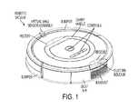
- FIG. 1is a top perspective view of an embodiment of a cleaning robot in accordance with the present teachings.
- FIG. 2Ais a cross sectional view of an exemplary embodiment of a robotic vacuum cleaning head in accordance with the present teachings.
- FIG. 2Bis a cross sectional view of another exemplary embodiment of a robotic vacuum cleaning head in accordance with the present teachings.
- FIG. 3is a cross sectional view of the embodiment of a cleaning head depicted in FIG. 2A , in combination with a corresponding removable dust bin.
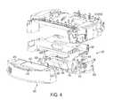
- FIG. 4is an exploded rear perspective view of the cleaning head and dust bin embodiment of FIGS. 2A and 3 .
- FIG. 5is a side rear perspective view of the cleaning head and dust bin embodiment of FIG. 2B .
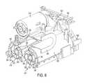
- FIG. 6is a partial side perspective cross-sectional view of the cleaning head embodiment of FIGS. 2A , 3 , and 4 .
- FIG. 7is a side perspective view of an exemplary motor and cleaning head gear box for the cleaning head shown in FIG. 2B .
- FIG. 8is a side perspective view of an embodiment of an impeller assembly in accordance with the present teachings, for use in a cleaning head such as that shown in FIG. 2B .
- FIG. 9is a cross-sectional view of the cleaning head embodiment of FIG. 5 , taken through the impeller shown in FIG. 8 .
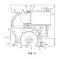
- FIG. 10is a cross-sectional view of an embodiment of the cleaning head in accordance with FIG. 2B .
- FIG. 11is a side view of the cleaning head embodiment of FIG. 3 , showing two arms of a four-bar linkage.
- FIG. 12is another side view of the cleaning head embodiment of FIG. 3 , showing two other arms of the four-bar linkage.
- FIG. 13is a perspective view of an exemplary arm for a four-bar linkage suspension in accordance with the present teachings.
- FIG. 14is a perspective view of another exemplary arm for a four-bar linkage suspension in accordance with the present teachings.
- FIG. 15is bottom perspective view of the embodiment of FIG. 3 .
- FIG. 16is bottom perspective view of a portion of the cleaning head embodiment of FIG. 3 with a roller frame opened to expose the rollers.
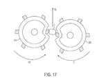
- FIG. 17illustrates, schematically, passage of large debris through exemplary collapsible resilient rollers in accordance with embodiments of the present teachings.
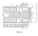
- FIG. 18is a partial cross-sectional view of an exemplary embodiment of a driven end of a roller in accordance with the present teachings.
- FIG. 19is a partial cross-sectional view of an exemplary embodiment of a non-driven end of a roller in accordance with the present teachings.
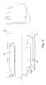
- FIG. 20is a side perspective view of an exemplary embodiment of resilient rollers in accordance with the present teachings.
- FIG. 21is an exploded side perspective view of an exemplary embodiment of a resilient roller in accordance with the present teachings.
- FIG. 22is a cross-sectional view of an exemplary embodiment of a roller having a spoked resilient support in accordance with the present teachings.
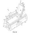
- FIG. 23is a front perspective view of a dust bin accordance with the present teachings, having a front bin door open.
- FIG. 24is a top perspective view of the dust bin of FIG. 24 , having a filter access door open.
- FIG. 25is a top perspective view of the dust bin of FIG. 24 , having the bin top and filter removed.
- FIG. 26is a cross sectional view of the dust bin of FIG. 23 , taken through the impeller housing.
- FIGS. 27A to 27Cschematically illustrate three positions for an exemplary cleaning assembly suspension in accordance with the present teachings.
- FIGS. 28A and 28Bshow section views of an example cleaning robot.
- FIG. 29is a bottom view of an example cleaning robot.
- the present teachingscontemplate a cleaning head or cleaning head assembly utilizing at least one, and for example two, rollers having collapsible but resilient cores.
- Embodiments of the collapsible but resilient rollerinclude an outer tubular surface having vanes extending there from.
- the outer tubular surfacecan be supported underneath with a resilient support system including, for example, one or more of a foam material and a flexible spoke.
- the flexible spokes and foamcan be designed to have a curvature, size, and composition suitable to obtain a desired roller flexibility and resiliency. While it may be desirable, in certain embodiments, for the flexibility and resiliency of the roller to be consistent along an entire length of the roller, the present teachings contemplate embodiments wherein the flexibility and resiliency of the roller varying along its length.
- the foam supportcan simply be glued to a vane tubular outer tube of the flexible, resilient roller, and can be provided along the entire length of the roller.
- the rollercan be molded to have resilient spokes supporting the tubular tube along the entire length of the roller.
- the tubular tubecan be provided by both resilient spokes and foam, for example utilizing resilient spokes in a center portion of the roller and foam at it souter edges, or vice versa.
- the tubular tubecan be keyed to a drive shaft to transfer torque from the drive shaft to the tubular tube to turn the roller appropriately in the cleaning head.
- vanes extending from an outer surface of the tubular tube, from one of the roller to the other end of the rollercan have a generally chevron-type shape.
- the chevron-type shapecan facilitate movement of debris swept by the roller toward a center of the roller (i.e., toward a point of the chevron) so that debris such as hair does not get caught in the ends of the rollers where it can interfere with operation of the roller and thus the cleaning head.
- the point of one vane chevroncan be tangent with the apex of an adjacent vane.
- a trailing (rear) rollercan be set lower that a leading (front) roller.
- Embodiments of the present teachingscan also employ a linkage within the cleaning head attaching the rollers to the cleaning head frame that allows the cleaning head to float the cleaning head leading edge higher than a the cleaning head trailing edge. Keeping the leading roller elevated can prevent the leading roller, which typically rotates in the same direction as the wheels of the robotic vacuum during its forward motion, from digging into carpeting during operation of the vacuum.
- the trailing rollertypically rotates in a the opposite direction from the wheels of the robotic vacuum during its forward motion, and therefore tends to not run the risk of digging into carpeting as it encounters and/or moves across carpeting.
- the front rollercan be aligned, for example, with a bottom portion of the cleanings head, structure, so as to not protrude beyond it.
- one collapsible, resilient rollercan be aligned parallel to and “face” another roller.
- the other rollercan similarly be collapsible and resilient. “Facing” the other roller can mean that the chevron shapes of the roller vanes mirror each other as the rollers are installed in the cleaning head to be parallel with one another.
- the present teachingscan also pair a resilient collapsible roller as disclosed herein with a conventional robotic vacuum cleaning head roller or brush.
- a cleaning head in accordance with certain embodiment of the present teachingscan provide a high velocity air system, maximizing air flow velocity by situating the cleaning head rollers close together (with minimal spacing between them) so that the vanes thereon are close together, having an air intake tube of the cleaning head situated directly above the minimal space between the rollers.
- a roller frame and a lower housing of the cleaning headcan be shaped to minimize the space between the rollers and the portions of the cleaning head housing surrounding the rollers, to again minimize the area of vacuum flow to maximize its speed.
- the roller frame and a lower housing of the cleaning headshould be close enough to the rollers to maximize airflow or obtain a predetermined level of air flow, but should also be spaced from the rollers such that debris does not get wedged therein.
- airflowgoes straight up from the rollers into a vacuum inlet having a surface that can act as a deflecting surface (e.g., it is angled or curved) to bounce denser/heavier debris swept upward by the rollers toward a plenum that leads to the dust bin.
- Bouncing denser debris toward the plenum and dust binis better facilitated by an angled vacuum inlet, and such bouncing can assist the vacuum in moving denser/heavier debris to the dust bin.
- the vacuum inletcan have a parabolic shape or a constant radius of curvature, although a parabolic shape is preferred. The vacuum inlet need not have a constant radius.
- the vacuum inletcan be shaped to help guide larger debris toward the center of the plenum, where the air velocity is highest.
- the vacuum inletdirects air into the plenum and can comprises a more rigid material for better wear resistance and to better bounce debris toward the dust bin.
- the plenumcan comprise a more flexible material that allows the cleaning head to float.
- the junction of the vacuum inlet and the plenumis overmolded to provide a smooth surface over which incoming air flows.
- airflow from the cleaning head through to the vacuum impelleris substantially sealed to prevent leaks from lowering vacuum strength.
- Various embodiments of the present teachingsemploy a sealed filter within the removable dust bin.
- the filteris located along the path of the air flow between the cleaning head and the vacuum impeller to prevent dust from migrating to the impeller.
- the filteris preferably removable but sealed when installed to prevent airflow leakage.
- Certain embodiments of the present teachingsinclude a “filter presence” indicator tab within a filter cavity. The filter presence indicator tab can prevent operation of the vacuum when the filter is not properly installed, for example by preventing a filter access door from closing such that the removable dust bin cannot be installed in the robotic vacuum.
- a robotic vacuum having a cleaning head and dust bin in accordance with the present teachingshas improved fluid dynamics due to one or more of the following: impeller design, impeller enclosure design, minimizing turns in the air path from the rollers to the vacuum impeller, minimizing the length of the path from the rollers to the vacuum impeller, minimizing any eddy-producing protrusions along the path from the rollers to the vacuum impeller.
- the improved fluid dynamicscan, for example, allow a lower-powered vacuum impeller (drawing less battery power) to provide a suitable amount of airflow for the robotic vacuum.
- air flow velocitycan additionally or alternatively be maximized by maintaining a substantially constant cross sectional area of air flow across the filter and into the impeller.
- the cleaning head rollers/brushes disclosed and illustrated hereinmay include, for example, brushes as disclosed in U.S. patent application Ser. No. 13/028,996, filed Feb. 16, 2011, titled Vacuum Brush, the disclosure of which is incorporated by reference herein in its entirety.
- “climb rotation”shall mean a rotation of a roller that opposes the direction of forward movement of the robot, i.e., that is opposite to the rotation of the drive wheels as the robot moves in a forward direction.
- “Roll rotation”shall mean the opposite direction, i.e., a rotation of the roller that is in the same direction as the rotation of the drive wheels in a forward direction. Such rotation need not be at the same speed as the drive wheels, and the directional description is for reference purposes, i.e., a roller may rotate in “climb rotation” even if the robot is stationary or moves backward.
- “Tube”, as used herein,means “covering tube” and need not have a terminal or sealed end.
- “Linkage”has its ordinary meaning, and is considered to encompass planar linkages, four-bar linkages, slider-crank linkages, and arrangements of link members with pivots, springs, wires, strings, cords, cams, and/or grooves.
- FIG. 1is a top perspective view of an embodiment of a cleaning robot in accordance with the present teachings.
- FIGS. 2A and 2Bare cross sectional views of different embodiments of a similar portion of a robotic vacuum, each depicting an embodiment of a cleaning head 300 , 100 in accordance with the present teachings.
- the following descriptionshall describe common features of different embodiments; as well as pairs of matching features within one embodiment, using reference numerals separated by a comma.
- the cleaning headincludes a front roller 310 , 110 and a rear roller 320 , 120 , each roller having an axle 330 , 130 that is preferably substantially rigid and not collapsible and a collapsible, resilient core 340 , 140 surrounding the axle 330 , 130 .
- the collapsible, resilient core 340 , 140can comprise, for example, a foam material, or other resilient material such as curvilinear spokes, discussed in further detail below.
- “Collapsible roller” as used hereinmeans a roller with a substantially contiguous tubular outer surface. Upon material external pressure, the tubular outer surface bends or deforms, and upon relief of such pressure, resiliently returns to its former shape, like a balloon, ball, or “run-flat” tire.
- the rollers 310 , 320 , 110 , 120preferably have a circular cross section.
- the collapsible, resilient core 340 , 140can be surrounded by a tube 350 , 150 having chevron vanes 360 , 160 .
- the chevron vanes 360 , 160are chevron-shaped and, for example, spaced at equal intervals 170 around the tube 350 , 150 , although the present teachings contemplate a variety of vane spacing intervals and shapes.
- the chevron vanes 360 , 160may be arranged as 5, 6, 7, 8, or 9 regularly spaced chevron vanes, and are integral with the collapsible tube 350 , 150 (preferably injection molded as a complete part) and deform together with the collapsible tube 350 , 150 .
- the height H (see FIG. 2 ) of the chevron vanes 360 , 160can be selected to bridge a preselected amount of a gap G between the front roller 310 , 110 and the rear roller 320 , 120 , for example at least about half of the gap G between the front roller 310 , 110 and the rear roller 320 , 120 .
- the gap G between the front roller 310 , 110 and the rear roller 320 , 120is about 7 mm, and the height H of the vanes 360 , 160 is about 3 mm, making the gap g between the vanes 360 , 160 about 1 mm.
- a roller frame 380 , 180 and the lower housing 390 , 190 of the cleaning head 300 , 100can be shaped to complement the outer shape of rollers 310 , 320 , 110 , 120 such that the roller frame 380 , 180 and lower housing 390 , 190 are close enough to the rollers to maximize airflow in the gap G between the rollers 310 , 320 , 110 , 120 , but should also be spaced from the rollers such that debris does not get wedged therein.
- Proximity of the roller frame 380 , 180 and the lower housing 390 , 190 to the rollers 310 , 320 , 110 , 120resists air from being pulled from an outboard gap OG, so that the vacuum pull will be stronger within the gap G between the rollers 310 , 320 , 110 , 120 .
- the clearance between the chevron vanes 360 , 160 (or other outermost portion of the rollers 310 , 320 , 110 , 120 ) and the surrounding portions of the roller frame 380 , 180 and the lower housing 390 , 190can be about 1 mm.
- aircan be pulled through the air gap G between the front roller 310 , 110 and the rear roller 320 , 120 , for example by an impeller housed within or adjacent to the cleaning head.
- the impellercan pull air into the cleaning head from the environment below the cleaning head, and the resulting vacuum suction can assist the rollers 310 , 320 , 110 , 120 in pulling dirt and debris from the environment below the cleaning head 300 , 100 into a dust bin of the robotic vacuum.
- the vacuum impellerpulls air (airflow being indicated by the arrows) through a vacuum inlet 392 , 200 to a central plenum 394 , 210 that can extend between the vacuum inlet 392 , 200 and the dust bin (not shown in FIG. 1 ).
- FIG. 3is a cross sectional view of, with reference to the embodiment of FIG. 2A , a portion of a robotic vacuum having an embodiment of a cleaning head 300 and an embodiment of a removable dust bin 400 in accordance with the present teachings.
- Aircan be pulled through the air gap between the front roller 310 and the rear roller 320 , for example by a vacuum impeller housed within or adjacent to the cleaning head 300 .
- the impellercan pull air into the cleaning head from the environment below the cleaning head, and the resulting vacuum suction can assist the rollers 310 , 320 in pulling dirt and debris from the environment below the cleaning head 300 into the dust bin 400 of the robotic vacuum.
- the vacuum impellershown in FIGS.
- the vacuum inlet 392has an angled surface that can act as a deflecting surface such that debris swept upward by the rollers and pulled upward by the vacuum suction can strike the angled wall of the vacuum inlet 392 and bounce toward the central plenum 394 and the dust bin 400 .
- Bouncing denser debris toward the central plenum 394 and dust bin 400is better facilitated by an angled vacuum inlet, for example having an angle of inclination with respect to the horizontal of from about 30° to about 60°.
- the vacuum inlet 392directs air into the central plenum 394 .
- the vacuum inlet 392can comprise a more rigid material for better wear resistance and to better bounce debris toward the dust bin 400 .
- the central plenum 394can comprise a more flexible material that allows the cleaning head 300 to “float” with respect to cleaning head frame 398 and the dust bin 400 .
- the central plenum 394is made of an elastomer approximately half the thickness or thinner than the relatively rigid plastic of the introductory plenum 392 .
- the junction of the vacuum inlet 392 and the central plenum 394is overmolded or otherwise smoothed at joint 396 to provide a smooth surface over which incoming air flows.
- a seal(not shown) can be provided to reduce friction, provide wear resistance, and serve as a face seal between the cleaning head 300 and the dust bin 400 .
- Seals within the cleaning head and the dust binmay be subject to a combination of rotation and translation forces along their surfaces as the cleaning head moves up and down within the robotic vacuum chassis. In such cases, sealed surfaces may be forced or biased toward one another with mechanical engagements that accommodate such rotation and translation (such as, e.g., elastomer to elastomer butt joints and/or interlocking joints).
- the illustrated exemplary removable dust bin 400includes a release mechanism 410 that can be, for example, spring-loaded, a cavity 420 for debris collection, a removable filter 430 , and a filter door 440 that, in the illustrated embodiment, provides an air flow cavity 445 that allows air to flow from the filter to a vacuum impeller housed within the dust bin.
- the cavity 420has a collection volume.
- the exemplary dust binis described in greater detail below.
- FIG. 4is an exploded rear perspective view of the cleaning head 300 and the dust bin 400 embodiments of FIG. 3 .
- the dust bin 400includes a release mechanism 410 and a filter door 440 .
- the vacuum impellerwould be housed within the dust bin under the portion 450 depicted in FIG. 5 .
- the portion 450 of FIG.can be a removable panel allowing access to the vacuum impeller.
- a chassislies above the cleaning head frame 398 .
- a roller motor 610is illustrated at a front of the cleaning head 300 , and a gear box 620 is shown that performs gear reduction so that the roller motor 610 can drive the rollers that are positioned under the roller housing 390 .
- the central plenum 394 and vacuum inlet 392are also shown.
- the exhaust vent for exhaust air exiting the binis directed through a series of parallel slats angled upward, so as to direct airflow away from the floor. This prevents exhaust air from blowing dust and fluff on the floor as the robot passes.
- the cleaning head 300is supported by a ‘four bar linkage’, ‘slider-crank linkage’, or equivalent mechanism permitting the front of the cleaning head 300 to move upward at a slightly faster rate than the rear.
- the very front of the cleaning head 300 , integral with the floating linkis synthesized to lift at a higher rate than the very rear (e.g., 100% to 120% rate).
- the cleaning head 300 , integral with the floating linkis synthesized to lift to start with a small angle lift (e.g., 0% to 5%) and end with a higher angle lift (e.g., 1% to 10%).
- the cleaning head 300integral with the floating link, is synthesized to translate upwards by a fixed amount and to simultaneously, or later in the synthesis, rotate up by a small angle (0% to 10%). Synthesis of the linkage through three positions or two positions, function generation, path generation, or motion generation, as is known in the art, determines the links' lengths and pivot locations.
- FIGS. 27A to 27Cshow a suspended position; a hard floor operating position, and a position as the robot and cleaning head encounter a carpet or rug.
- a first link 630 and a second link 640 (grounded links) of a four-bar linkageare shown on a right side of the FIG. 4 depiction of the cleaning head 300 , and are substantially similar to the two linkages 530 , 560 of the four-bar linkage of FIG. 5 (described below).
- the cleaning headforms a floating link between the joints connecting the two grounded links 630 , 640 , and the chassis supports the fixed link.
- the links 630 , 640extend adjacent to the roller gearbox 620 and connect to roller gearbox 620 to the frame 398 so that the roller gearbox 620 (and thus the rollers connected thereto) can “float” with respect to the frame 398 .
- Another second link 650 of a second, parallel four-bar linkageis shown on the opposite side of the cleaning head 300 .
- Another first link 660 of the second, parallel four-bar linkagecan also be seen located under the second link 650 .
- the links 640 , 650 , and 660are substantially straight.
- the first link 630 of the illustrated four-bar linkagehas a bent, somewhat shallow V-shape.
- FIG. 5is a front perspective view of the second embodiment of a cleaning head in accordance with the present teachings, such as the cleaning head illustrated in FIG. 2B .
- the impelleris positioned within the robot body rather than within the cleaning bin, and vacuum airflow is drawn through the bin via vacuum inlet 200 .
- a central plenum 210 and vacuum inlet 200can be seen, as well as an air input 520 to a vacuum impeller 500 .
- the vacuum impeller 500 , a motor 510 , and a roller gearbox 530can also be seen in FIG. 5 .
- the second (grounded) link 570 of the far-sidein FIG.
- four-bar linkagecomprises an exemplary L-shaped wire connecting the cage 540 to an impeller housing, which is illustrated in more detail below.
- a wireis used as the second link 570 to provide more room in the cleaning head 100 for the impeller 500 , in embodiments of the present teachings accommodating the vacuum impeller within the cleaning head.
- Advantages of housing the impeller within the cleaning headcan include facilitating a larger dust bin cavity and allowing the same motor to power the impeller and the rollers.
- FIG. 6is a partial side perspective cross-sectional view of the cleaning head embodiment of FIGS. 2A and 4 .
- the relationship of the front roller 310 , rear roller 320 , vacuum inlet 392 , central plenum 394 , roller motor 610 , and roller gearbox 620can be seen.
- the roller motor 610drives both the front roller 310 and the rear roller 320 via the gear box 620 in a known manner.
- the roller motor 610rotates the front roller 310 in a roll rotation direction to sweep debris from the floor at an angle toward the rear roller 320 , and the roller motor 610 rotates the rear roller 320 in a climb rotation direction to catch the debris launched by the front roller 310 (and other debris) and sweep that debris further upward at an angle toward the vacuum inlet and the suction provided by a vacuum impeller.
- the debriscan bounce off of the rigid, angled surface of the vacuum inlet 392 through the central plenum 394 and into the dust bin 400 .
- the illustrated roller axles 330are preferably not collapsible and are capable of transferring torque, via key features 335 , from the gearbox 620 through to the rollers 310 , 320 .
- the illustrated axles 330can be solid or hollow, and can be keyed at 335 to facilitate rotating torque transfer to the rollers 310 , 320 . Also shown are curved spokes 340 to provide collapsible but resilient support to the roller tube 350 .
- FIGS. 7 , 8 , 9 , 10 A, and 10 BAnother embodiment of a cleaning head drive system, complementary to the cleaning head arrangement of FIGS. 2B and 5 , is illustrated in FIGS. 7 , 8 , 9 , 10 A, and 10 B.
- the illustrated exemplary drive systemcan be used with the cleaning head of FIG. 5 , and in contrast to the embodiment of FIGS. 2A , 4 , and 6 , includes a motor 510 that can drive both a vacuum impeller and two cleaning head rollers.
- a vacuum impeller, such as impeller 500 shown in FIG. 4can be driven by an output shaft 700
- a front rollere.g., front roller 110 in FIG. 1
- a rear rollere.g., rear roller 120 in FIG.
- a cleaning head gear box of 730contains gears that allow the motor, having a given rotational speed sufficient to drive a vacuum impeller, to drive the front roller at a desired rotational speed in a roll rotation direction and the rear roller at a desired rotational speed in a climb rotation direction.
- the illustrated exemplary cleaning head gear box 730includes a gearbox housing 740 being illustrated as transparent so that the gears can be seen.
- roller drive shafts 720 , 710are shown extending from a first gear 750 and a fourth gear 758 , the roller drive shafts 710 , 720 being used to drive the front and rear cleaning head rollers 110 , 110 , respectively.
- FIG. 7also shows the motor output shaft 700 for connection to a vacuum impeller drive shaft (see FIG. 8 ), the motor output shaft 700 extending directly from a first end of the motor 510 .
- Another output shaft of the motor 510extends from an opposite end of the motor into the cleaning head gearbox 730 to drive the rollers.
- the rotational velocity of the front roller and the rear rollercan be different than the rotational velocity of the motor output, and can be different than the rotational velocity of the impeller.
- the rotational velocity of the impellercan be different than the rotational velocity of the motor. In use, the rotational velocity of the front and rear rollers, the motor, and the impeller can remain substantially constant.
- FIG. 8is a side perspective view of an exemplary embodiment of a vacuum impeller assembly 800 in accordance with the present teachings, to be used together with the assembly of FIG. 7 .
- the illustrated impeller assembly 800can be used in a cleaning head such as the cleaning head 100 shown in FIG. 4 .
- the assembly 800includes an impeller 500 , a coupler 810 that can be coupled to the motor output shaft 700 shown in FIG. 7 , an impeller drive shaft 820 , an impeller housing 830 including an outer portion 832 and an inner portion 834 , the inner portion 834 of the impeller housing 830 including an air outlet 840 that directs air exiting the impeller 500 back into the environment.
- a gearbox cover 850is shown to run along the outer portion of the impeller housing 830 , the gearbox cover protecting gears (not shown) that provide a gear reduction from the drive shaft 820 to the impeller 500 .
- the drive shaft 820is a 2 mm steel shaft and bushings support the drive shaft on either end.
- ribs on the impeller housing 830can stiffen the housing to prevent deformation under loading and to limit vibration for sound reduction.
- the illustrated impeller housing 830includes a connection point 860 for the link 570 shown in FIG. 5 , such that the link 570 can connect the impeller housing 830 to the cage 540 to facilitate “floating” of the rollers within the chassis.
- FIG. 9is a cross-sectional view of an embodiment of the robotic vacuum cleaning head 100 of FIG. 5 , taken through the impeller 500 and a portion of the air inlet 520 .
- the front roller 110can also be seen, with a portion of the vacuum inlet 200 above it.
- a portion of the air inlet 520 to the impeller 500is shown, the air inlet conduit mating with in inner portion 900 of the impeller housing as shown.
- the impeller 500is enclosed by the inner portion 900 of the impeller housing and an outer portion 910 of the impeller housing.
- a gear 920 of the impeller gearboxis shown along with bushings 930 on each side thereof, which are housed between the outer portion 910 of the impeller housing and the gearbox cover 850 .
- the illustrated impeller 500includes an inner portion 940 and an outer portion 950 that can, for example, be snapped together, fastened, adhered, or integrally molded. In use, air is pulled by the impeller 500 from the dust bin through the air inlet.
- FIGS. 10A and 10Bare is a cross-sectional views of the cleaning head of FIGS. 2B and 5 , showing respectively the plenum 210 in cutaway and the impeller air inlet conduit 520 in cutaway.
- the central plenum 210is a low-friction plenum comprising, for example, a polyoxymethylene (e.g, Delrin®), which is an engineering thermoplastic used in precision parts that require high stiffness, low friction and excellent dimensional stability.
- a felt seal 220can be provided to reduce friction, provide excellent wear resistance, and serve as a face seal between the cleaning head 100 and the dust bin (not shown). All seals within the cleaning head and between the cleaning head and the dust bin will be subject to a combination of rotation and translation forces along their surfaces as the cleaning head moves up and down within the robotic vacuum chassis.
- FIG. 2is a partial cross sectional view of the robotic vacuum cleaning head environment of FIG. 1 , illustrating an exemplary embodiment of an annular seal 230 that can be employed between the vacuum conduit 200 and the central plenum 210 .
- the illustrated annular seal 230can be mounted to a protrusion 240 extending from an end of the vacuum conduit 200 , the annular seal 230 facilitating a substantially airtight mating between the vacuum conduit 200 and an opening 250 of the central plenum 210 .
- the illustrated exemplary annular seal 230includes a rubber lip 260 configured to maintain an airtight seal between the vacuum conduit 200 and the central plenum 210 , while allowing the vacuum conduit 200 and central plenum 210 to move relative to each other during operation of the robotic vacuum.
- the vacuum conduit 200 and the central plenum 210may move relative to each other as the cleaning head moves relative to the robotic vacuum chassis.
- the central plenum opening 250has an increased radius to accommodate the vacuum conduit 200 and the annular seal 230 , and provide room for relative movement of the vacuum conduit 200 and the central plenum 210 .
- the impeller inlet conduit 520is shown to include two portions, a front portion 1010 and a rear portion 1020 .
- the rear portion 1020extends from the dust bin to the front portion 1010 .
- the front portion 1010extends from the rear portion 1020 to the impeller 500 .
- a rotating and sliding seal arrangement 1030is shown to mate the front portion 1010 of the air inlet conduit 520 with the rear portion 1020 of the air inlet conduit 520 .
- the sliding seal arrangement 1030 between the front portion 1010 and the rear portion 1020 of the air inlet conduit 520includes lips/protrusions (two are shown in the illustrated embodiment) that maintain an airtight seal between the air inlet and the air input duct, while allowing the air inlet and the air input duct to move relative to each other during operation of the robotic vacuum, and particularly while portions of the cleaning head “float” using the four-bar linkage described herein.
- FIG. 11shows a left side view of a cleaning head of FIG. 4 , wherein the frame 398 is shown, along with the attached link 650 and link 660 of one side's four-bar linkage that allows portions of the cleaning head 300 to move with respect to the frame 398 and thus the robotic vacuum chassis; and
- FIG. 12shows a right side view of the cleaning head of FIG. 4 , wherein the frame 398 is shown, along with the attached link 630 and fourth link 640 of the opposite side's four-bar linkage that allows portions of the cleaning head 300 to move with respect to the frame 398 and thus the robotic vacuum chassis.
- the four-bar linkage(s)operates to lift the front roller a slightly faster rate than the rear roller.
- the four-bar linkageis “floating” the cleaning head, and the linkages have slightly different lengths (e.g., only millimeters different) and the points of attachment to the frame, cage, or cleaning head do not form a rectangle or a parallelogram.
- FIGS. 13 and 14are perspective views of an exemplary links for a four-bar linkage suspension in accordance with the present teachings, for example the link 550 of the embodiment of FIG. 4 or the link 640 of the embodiment of FIG. 12 .
- FIG. 13depicts a substantially straight link;
- FIG. 14depicts one having a bent, somewhat shallow V-shape.
- the armscan comprise, for example, PEI, PC, Acetal, Nylon 6, PBT, PC/PET, ABS, PET, or a combination thereof.
- FIG. 15is a bottom perspective view of the cleaning head 300 and dust bin 400 embodiment of FIG. 5 , with the dust bin 400 removably engaged with the cleaning head 300 .
- the rollers 310 , 320are shown, along with the roller frame 380 in a closed position.
- a removable roller frame 380allowing access to the roller 310 , 320 for, for example, removal or cleaning of the rollers 310 , 320 .
- the roller frame 380can be releasably and hingedly attached to the gearbox 620 or the lower housing 390 , for example via hinges 1525 and tabs 1520 of a known sort.
- the tabs 1520can be pressed toward a front of the cleaning head to release the rear side of the roller frame 380 and the roller frame 380 can pivot open to provide access to the rollers 310 , 320 .
- the illustrated exemplary roller frame 380 shown in FIG. 15includes multiple prows 1500 on a forward edge. The prows can be provided to support the cleaning head as it floats across the surface to be cleaned, and also limit the size of debris that can enter the cleaning head to the size of the vacuum conduit.
- the illustrated exemplary roller frame 380also includes “norkers” 1510 that can be used to prevent cords and other long, thin material from getting pulled between the rollers 310 , 320 .
- a “norker”is a short, V-shaped trough as depicted.
- the “norkers” 1510are located at very end of the rollers 310 , 320 , and can additionally prevent larger debris from entering between the rollers 310 , 320 at the end of the rollers 310 where the rollers may not be as compressible.
- the tubular outer shell of the rollerwhich itself can deform substantially, abuts a hard cylindrical core at the end of the roller.
- the purpose of the “norker”is to prevent captured objects larger than a certain size (e.g., larger than the gap G) from jamming between the rollers at the very ends, where the rollers may not deform because of the hard cylindrical core at the roller end.
- a certain sizee.g., larger than the gap G
- FIG. 16is a bottom perspective view of the cleaning head of FIG. 15 , with the roller frame 380 open to expose the rollers 310 , 320 . As can be seen, some of the roller area covered by the norkers 1510 may not be the compressible, resilient tubing 350 of the rollers.
- the tabs 1520 that allow the roller frame 380 to release from the lower housing 390can releasably engage latching mechanisms 1535 of the lower housing 390 to close the roller housing 380 .
- the non-driven ends 1600 of the rollers 310 , 320are shown in FIG. 16 and an exemplary embodiment thereof is shown in FIG. 19 and described below.
- FIG. 17schematically illustrates a large piece of debris D being accommodated by the rollers 310 , 320 , the rollers being collapsible to allow the debris D to pass through a center of the rollers 310 , 320 , despite the size of the debris D being larger than the gap between the rollers.
- the rollerswill retain (rebound to) their circular cross section due to their resiliency and the debris will move upward toward a dust bin conduit in a direction V B .
- the front roller 310rotates in a roll rotation direction CC and the rear roller 320 rotates in a climb rotation direction C.
- FIG. 18is a cross sectional view of an exemplary driven end of an embodiment of a cleaning head roller (e.g., rollers 110 , 120 , 310 , 320 ) in accordance with the present teachings.
- the roller drive gear 1800is shown in the gearbox housing 1810 , along with a roller drive shaft 1820 and two bushings 1822 , 1824 .
- the roller drive shaft 1820can have, for example, a square cross section or a hexagonal cross section as would be appreciate by those skilled in the art.
- a shroud 1830is shown to extend from the within the roller tube 350 to contact the gearbox housing 1810 and the bearing 1824 and can prevent hair and debris from reaching the gear 1800 .
- the axle 330 of the rollerengages the roller drive shaft 1820 .
- the area of the axle 330 surrounding the drive shaft 1800includes a larger flange or guard 1840 and a smaller flange or guard 1850 spaced outwardly therefrom.
- the flanges/guards 1840 , 1850cooperate with the shroud 1830 to prevent hair and other debris from migrating toward the gear 1800 .
- An exemplary tube overlap region 1860is shown, where the tube 350 overlaps the shroud 1830 .
- the flanges and overlapping portions of the drive end shown in FIG. 18can create a labyrinth-type seal to prevent movement of hair and debris toward the gear.
- hair and debris that manages to enter the roller despite the shroud overlap region 1860can gather within a hair well or hollow pocket 1870 that can collect hair and debris in a manner that substantially prevents the hair and debris from interfering with operation of the cleaning head.
- Another hair well or hollow pocketcan be defined by the larger flange 1840 and the shroud 1830 .
- the axle and a surrounding collapsible corepreferably extend from a hair well on this driven end of the roller to a hair well or other shroud-type structure on the other non-driven end of the roller.
- curvilinear spokesreplace all or a portion of the foam supporting the tube 350 .
- FIG. 19is a cross sectional view of an exemplary non-driven end of an embodiment of a cleaning head roller (e.g., rollers 110 , 120 , 310 , 320 ) in accordance with the present teachings.
- a pin 1900 and bushing 1910 of the non-driven end of the rollerare shown seated in the cleaning head lower housing 390 .
- a shroudextends from the bushing housing 1920 into the roller tube 350 , for example with legs 1922 , to surround the pin 1900 and bushing 1910 , as well as an axle insert 1930 having a smaller flange or guard 1932 and a larger flange or guard 1934 , the larger flange 1934 extending outwardly to almost contact an inner surface of the shroud 1920 .
- An exemplary tube overlap region 1960is shown, where the tube 350 overlaps the shroud 1920 .
- the flanges/guards and overlapping portions of the drive end shown in FIG. 19can create a labyrinth-type seal to prevent movement of hair and debris toward the gear.
- the shroudis preferably shaped to prevent entry of hair into an interior of the roller and migration of hair to an area of the pin.
- hair and debris that manages to enter the roller despite the shroud overlap region 1960can gather within a hair well or hollow pocket 1970 that can collect hair and debris in a manner that substantially prevents the hair and debris from interfering with operation of the cleaning head.
- Another hair well or hollow pocketcan be defined by the larger flange 1934 and the shroud 1920 .
- FIG. 20illustrates exemplary facing, spaced chevron vane rollers such as the front roller 310 and rear roller 320 of FIG. 3 .
- the flanges 1840 and 1850 of the axle 330can be seen, as can the foam 140 supporting the tubular tube 350 .
- the rollers 310 , 320face each other, which means that, in the illustrated embodiment, the chevron-shaped vanes 360 are mirror images.
- Each chevron-shaped vane of the illustrated exemplary rollersinclude a central point 365 and two sides or legs 367 extending downwardly therefrom on the front roller 310 and upwardly therefrom on the rear roller 320 .
- the chevron shape of the vane 360can draw hair and debris away from the sides of the rollers and toward a center of the rollers to further prevent hair and debris from migrating toward the roller ends where they can interfere with operation of the robotic vacuum.
- FIG. 21illustrates a side perspective exploded view of an exemplary embodiment of a roller, such as roller 310 of FIG. 20 .
- the axle 330is shown, along with the flanges 1840 and 1850 of its driven end.
- the axle insert 1930 and flange 1934 of the non-driven endare also shown, along with the shroud 1920 of the non-driven end.
- Two foam inserts 140are shown, which fit into the tubular tube 350 to provide a collapsible, resilient core for the tube.
- the foam insertscan be replaced by curvilinear spokes (e.g., spokes 340 shown in FIG. 6 , or can be combined with curvilinear spokes.
- the curvilinear spokescan support the central portion of the roller 310 , between the two foam inserts 140 and can, for example, be integrally molded with the roller tube 350 and chevron vane 360 .
- FIG. 22illustrates a cross sectional view of an exemplary roller having curvilinear spokes 340 supporting the chevron vane tube 350 .
- the curvilinear spokescan have a first (inner) portion 342 curvilinear in a first direction, and a second (outer) portion 344 that is either lacks curvature or curves in an opposite direction.
- the relative lengths of the portionscan vary and can be selected based on such factors as molding requirements and desired firmness/collapsibility/resiliency.
- a central hub 2200 of the rollercan be sized and shaped to mate with the axle that drives the roller (e.g., axle 330 of FIG. 21 ).
- the illustrated rollerincludes two recesses or engagement elements/receptacles 2210 that are configured to receive protrusions or keys 335 (see FIG. 6 ) of the axle.
- the illustrated rollerincludes two recesses or engagement elements/receptacles 2210 that are configured to receive protrusions or keys 335 (see FIG. 6 ) of the axle.
- FIG. 23is a front perspective view of an exemplary embodiment of a dust bin 400 in accordance with the present teachings.
- the dust binincludes, on its top surface a release mechanism 410 and a filter door 440 .
- the vacuum impellerwould be housed within the dust bin under the portion 450 of the top surface of the bin.
- the portion 450 of the top surfacecan be a removable panel allowing access to the vacuum impeller.
- the embodiment of FIG. 23also illustrates a filter door release mechanism 2300 that, as shown in FIG. 24 , can include a resilient tab 2400 and a recess 2410 that the tab engages in a known manner.
- a door 2310 of the dust bin 400is shown in a open position, exposing hinges 2330 and the cavity 420 for debris collection.
- the door 2310includes an opening 2320 that preferably matches up in size and location with, for example, the central plenum 394 of the cleaning head 300 shown in FIGS. 5 and 6 .
- An impeller housing 2340is located within the housing. In the illustrated embodiment, the impeller housing 2340 is located toward a side of the dust bin cavity 420 .
- FIG. 24is a top perspective view of the dust bin 400 of FIG. 23 , showing the filter door 440 in an open position that exposes the filter 430 and the walls 442 , 444 , 446 that partially define the air flow cavity 445 that allows air to flow from the filter 430 to a vacuum impeller housed within the dust bin cavity 420 .
- air flows from the central plenume.g., central plenum 394 of FIG. 5
- the central plenume.g., central plenum 394 of FIG. 5
- the central plenume.g., central plenum 394 of FIG. 5
- the filter 430is preferably releasable and includes a tab 430 T that allows a user to remove the filter 430 from the dust bin, for example for cleaning and/or replacement.
- the exemplary embodiment of FIG. 24includes an optional a “filter presence” indicator tab 2430 within a filter cavity.
- the filter presence indicator tab 2430can, for example, prevent operation of the robotic vacuum when the filter 430 is not properly installed, for example by moving to a position that prevents the filter door 440 from closing, which in turn prevents the removable dust bin 400 from being installed in the robotic vacuum.
- the filteris sealed within the surrounding portion of the dust bin. The seal can be employed on the filter, on the dust bin, or on both the filter and the dust bin.
- FIG. 25is a top perspective view of a portion of the dust bin 400 of FIGS. 23 and 24 , with a top portion of the dust bin and the filter 430 removed.
- a multiple bars 2510are used to retain the filter 430 within the dust bin.
- a transverse cross sectional area of the air flow cavity 445e.g. a cross section taken transverse to the longitudinal axis
- FIG. 26is a cross sectional view of the dust bin of FIGS. 23-25 , taken through the impeller housing 2340 , the impeller motor 2610 , and the impeller 2620 . The pathway from the air flow cavity 445 to the impeller 2500 can be seen.
- the one or more vanesare integrally formed with the resilient tubular member and define V-shaped chevrons extending from one end of the resilient tubular member to the other end.
- the one or more chevron vanesare equidistantly spaced around the circumference of the resilient tube member.
- the vanesare aligned such that the ends of one chevron are coplanar with a central tip of an adjacent chevron. This arrangement provides constant contact between the chevron vanes and a contact surface with which the compressible roller engages. Such uninterrupted contact eliminates noise otherwise created by varying between contact and no contact conditions.
- the one or more chevron vanesextend from the outer surface of the tubular roller at an angle ⁇ between 30° and 60° relative to a radial axis and inclined toward the direction of rotation (see FIG. 20 ). In one embodiment the angle ⁇ of the chevron vanes is 45° to the radial axis. Angling the chevron vanes in the direction of rotation reduces stress at the root of the vane, thereby reducing or eliminating the likelihood of vane tearing away from the resilient tubular member. The one or more chevron vanes contact debris on a cleaning surface and direct the debris in the direction of rotation of the compressible roller.
- the vanesare V-shaped chevrons and the legs of the V are at a 5° to 10° angle ⁇ relative a linear path traced on the surface of the tubular member and extending from one end of the resilient tubular member to the other end (see FIG. 22 ).
- the two legs of the V-shaped chevronare at an angle ⁇ of 7°.
- the compressible rolleris manufacturable by molding processes. Angles steeper than 10° create failures in manufacturability for elastomers having a durometer harder than 80 A.
- the tubular member and curvilinear spokes and hubare injection molded from a resilient material of a durometer between 60 and 80 A.
- the resilient tubular memberis manufactured from TPU and the wall of the resilient tubular member has a thickness of about 1 mm.
- the inner diameter of the resilient tubular memberis about 23 mm and the outer diameter is about 25 mm.
- the resilient tubular member having a plurality of chevron vanesthe diameter of the outside circumference swept by the tips of the plurality of vanes is 30 mm.
- the one or more chevron vanesextend from the outer surface of the resilient tubular member by a height that is, in one embodiment, at least 10% of the diameter of the resilient tubular roller, they prevent cord like elements from directly wrapping around the outer surface of the resilient tubular member.
- the one or more vanestherefore prevent hair or other string like debris from wrapping tightly around the core of the compressible roller and reducing efficacy of cleaning.
- Defining the vanes as V-shaped chevronsfurther assists with directing hair and other debris from the ends of a roller toward the center of the roller, where the point of the V-shaped chevron is located.
- the V-shaped chevron pointis located directly in line with the center of a vacuum inlet of the autonomous coverage robot.
- the four-bar linkage embodiments discussed hereinabovefacilitate movement (“floating”) of the cleaning head within its frame.
- a bottom surface of the cleaning headremain substantially parallel to the floor, and in some embodiments, it is preferable that the front roller 110 , 310 be positioned slightly higher than the rear roller 120 , 320 during operation.
- the cleaning headshould be able to move vertically during operation, for example to accommodate floor irregularities like thresholds, vents, or moving from a vinyl floor to carpet.
- both the top and bottom linkscan be snap fit to the cleaning head assembly.
- the top linkconnects the frame to the outer portion of the impeller housing.
- the bottom linkalso connects the frame to the outer portion of the impeller housing.
- the frameis intended to remain fixed relative to the robotic vacuum chassis as the cleaning head components illustrated herein move relative to the frame and the chassis.
- the framecan be cutaway to allow full visual and physical access to linkages.
- the frameis intended to remain fixed relative to the robotic vacuum chassis as the cleaning head components illustrated herein move relative to the frame and the chassis.
- the linkagelifts at a variable rate (the front wheel lifting at a faster rate than the rearward wheel) such that maximum lift angle from resting state is less than 10°.
- the linkageis a four bar linkage symmetrically placed about the cleaning assembly such that the forward end of each bar linkage attaches adjacent a forward edge of the cleaning assembly.
- an autonomous coverage robothas a chassis having forward and rearward portions.
- a drive systemis mounted to the chassis and configured to maneuver the robot over a cleaning surface.
- a cleaning assemblyis mounted on the forward portion of the chassis and at has two counter rotating rollers mounted therein for retrieving debris from the cleaning surface, the longitudinal axis of the forward roller lying in a first horizontal plane positioned above a second horizontal plane on which the longitudinal axis of the rearward roller lies.
- the cleaning assemblyis movably mounted to the chassis by a linkage affixed at a forward end to the chassis and at a rearward end to the cleaning assembly. When the robot transitions from a firm surface to a compressible surface, the linkage lifts the cleaning assembly from the cleaning surface. The linkage lifts the cleaning assembly substantially parallel to the cleaning surface but such that the front roller lifts at a faster rate than the rearward roller.
- the central plenumcomprises a substantially horizontal elastomeric portion leading into the collection volume.
- the substantially horizontal elastomeric portionflexes to create a downward slope when the linkage lifts the cleaning assembly to accommodate height differentials in cleaning surfaces.
- the substantially horizontal elastomeric portionflexes in a vertical dimension at least 5 mm such that debris lifted from the cleaning surface by the rollers travels up into the plenum and is directed down into the enclosed dust bin.
- FIGS. 28A and 28Billustrate flexure of the central plenum 394 to create a downward slope as the linkage lifts the cleaning assembly when the robotic vacuum is placed on a cleaning surface, for example prior to or during operation of the robotic vacuum.
- the front portion and rear portion of the vacuum airwaymay be formed as a unitary, monolithic component, but in some embodiments the rear portion is an elastomeric member adjoined to a rigid front portion at sealed joint.
- the sealed joinedis a compression fit wherein the rigid front portion is inserted into an elastomeric rear portion and affixed by radial compression forces.
- the sealed jointis an elastomeric overmold. The sealed joint forms a sealed vacuum path that prevents vacuum loses.
- the rear portionterminates in a flange abutting an opening to the debris collection bin in a sealed configuration. The vacuum airway therefore enables a smooth, sealed vacuum airflow.
- the elastomeric rear portionis manufactured from a thermoplastic material such as MedipreneTM or a thermoplastic vulcanizate (TPV) such as SantopreneTM.
- the rigid from portionis manufactured from a plastic material such as acrylonitrile butadiene styrene (ABS) or Nylon, which materials have anti-static properties and resist the accumulation of hair.
- FIG. 29is a bottom view of an embodiment of a cleaning robot in accordance with the present teachings.
Landscapes
- Engineering & Computer Science (AREA)
- Mechanical Engineering (AREA)
- Robotics (AREA)
- Nozzles For Electric Vacuum Cleaners (AREA)
- Electric Vacuum Cleaner (AREA)
- Electric Suction Cleaners (AREA)
- Manipulator (AREA)
- Filters For Electric Vacuum Cleaners (AREA)
- Rollers For Roller Conveyors For Transfer (AREA)
Abstract
Description
Claims (37)
Priority Applications (2)
| Application Number | Priority Date | Filing Date | Title |
|---|---|---|---|
| US13/460,347US9220386B2 (en) | 2011-04-29 | 2012-04-30 | Robotic vacuum |
| US14/947,826US9675224B2 (en) | 2011-04-29 | 2015-11-20 | Robotic vacuum cleaning system |
Applications Claiming Priority (2)
| Application Number | Priority Date | Filing Date | Title |
|---|---|---|---|
| US201161481147P | 2011-04-29 | 2011-04-29 | |
| US13/460,347US9220386B2 (en) | 2011-04-29 | 2012-04-30 | Robotic vacuum |
Related Child Applications (1)
| Application Number | Title | Priority Date | Filing Date |
|---|---|---|---|
| US14/947,826ContinuationUS9675224B2 (en) | 2011-04-29 | 2015-11-20 | Robotic vacuum cleaning system |
Publications (2)
| Publication Number | Publication Date |
|---|---|
| US20120311813A1 US20120311813A1 (en) | 2012-12-13 |
| US9220386B2true US9220386B2 (en) | 2015-12-29 |
Family
ID=46085197
Family Applications (9)
| Application Number | Title | Priority Date | Filing Date |
|---|---|---|---|
| US13/460,347Active2034-10-30US9220386B2 (en) | 2011-04-29 | 2012-04-30 | Robotic vacuum |
| US13/460,261Active2033-02-05US8881339B2 (en) | 2011-04-29 | 2012-04-30 | Robotic vacuum |
| US14/302,469ActiveUS8955192B2 (en) | 2011-04-29 | 2014-06-12 | Robotic vacuum cleaning system |
| US14/302,474ActiveUS8910342B2 (en) | 2011-04-29 | 2014-06-12 | Robotic vacuum cleaning system |
| US14/588,077ActiveUS9320400B2 (en) | 2011-04-29 | 2014-12-31 | Robotic vacuum cleaning system |
| US14/947,826Active2032-06-20US9675224B2 (en) | 2011-04-29 | 2015-11-20 | Robotic vacuum cleaning system |
| US15/590,411Active2032-12-19US10433696B2 (en) | 2011-04-29 | 2017-05-09 | Robotic vacuum cleaning system |
| US17/966,317ActiveUS12220096B2 (en) | 2011-04-29 | 2022-10-14 | Robotic vacuum cleaning system |
| US19/043,478PendingUS20250176783A1 (en) | 2011-04-29 | 2025-02-02 | Robotic vacuum cleaning system |
Family Applications After (8)
| Application Number | Title | Priority Date | Filing Date |
|---|---|---|---|
| US13/460,261Active2033-02-05US8881339B2 (en) | 2011-04-29 | 2012-04-30 | Robotic vacuum |
| US14/302,469ActiveUS8955192B2 (en) | 2011-04-29 | 2014-06-12 | Robotic vacuum cleaning system |
| US14/302,474ActiveUS8910342B2 (en) | 2011-04-29 | 2014-06-12 | Robotic vacuum cleaning system |
| US14/588,077ActiveUS9320400B2 (en) | 2011-04-29 | 2014-12-31 | Robotic vacuum cleaning system |
| US14/947,826Active2032-06-20US9675224B2 (en) | 2011-04-29 | 2015-11-20 | Robotic vacuum cleaning system |
| US15/590,411Active2032-12-19US10433696B2 (en) | 2011-04-29 | 2017-05-09 | Robotic vacuum cleaning system |
| US17/966,317ActiveUS12220096B2 (en) | 2011-04-29 | 2022-10-14 | Robotic vacuum cleaning system |
| US19/043,478PendingUS20250176783A1 (en) | 2011-04-29 | 2025-02-02 | Robotic vacuum cleaning system |
Country Status (10)
| Country | Link |
|---|---|
| US (9) | US9220386B2 (en) |
| EP (5) | EP2701570B1 (en) |
| JP (6) | JP5965474B2 (en) |
| CN (5) | CN107019467B (en) |
| AU (2) | AU2012249245B2 (en) |
| CA (2) | CA2833035C (en) |
| DE (2) | DE112012001933T8 (en) |
| ES (2) | ES2732069T3 (en) |
| GB (2) | GB2505127B (en) |
| WO (2) | WO2012149572A2 (en) |
Cited By (23)
| Publication number | Priority date | Publication date | Assignee | Title |
|---|---|---|---|---|
| US10168709B2 (en) | 2016-09-14 | 2019-01-01 | Irobot Corporation | Systems and methods for configurable operation of a robot based on area classification |
| US10292554B2 (en) | 2016-10-28 | 2019-05-21 | Irobot Corporation | Mobile cleaning robot with a bin |
| US10512384B2 (en) | 2016-12-15 | 2019-12-24 | Irobot Corporation | Cleaning roller for cleaning robots |
| US10575696B2 (en) | 2016-07-13 | 2020-03-03 | Irobot Corporation | Autonomous robot auto-docking and energy management systems and methods |
| US10595624B2 (en) | 2017-07-25 | 2020-03-24 | Irobot Corporation | Cleaning roller for cleaning robots |
| US10646091B2 (en) | 2006-05-19 | 2020-05-12 | Irobot Corporation | Coverage robots and associated cleaning bins |
| US10779695B2 (en) | 2017-12-29 | 2020-09-22 | Irobot Corporation | Debris bins and mobile cleaning robots including same |
| US10860029B2 (en) | 2016-02-15 | 2020-12-08 | RobArt GmbH | Method for controlling an autonomous mobile robot |
| US10895515B2 (en) | 2018-03-15 | 2021-01-19 | CGRS, Inc. | Methods and apparatus for detection of leaks in underground storage tanks |
| US10905297B2 (en) | 2018-01-05 | 2021-02-02 | Irobot Corporation | Cleaning head including cleaning rollers for cleaning robots |
| US11014460B2 (en) | 2007-05-09 | 2021-05-25 | Irobot Corporation | Compact autonomous coverage robot |
| US11020860B2 (en) | 2016-06-15 | 2021-06-01 | Irobot Corporation | Systems and methods to control an autonomous mobile robot |
| US11109727B2 (en) | 2019-02-28 | 2021-09-07 | Irobot Corporation | Cleaning rollers for cleaning robots |
| US11175670B2 (en) | 2015-11-17 | 2021-11-16 | RobArt GmbH | Robot-assisted processing of a surface using a robot |
| US11188086B2 (en) | 2015-09-04 | 2021-11-30 | RobArtGmbH | Identification and localization of a base station of an autonomous mobile robot |
| US11471020B2 (en) | 2011-04-29 | 2022-10-18 | Irobot Corporation | Robotic vacuum cleaning system |
| US11550054B2 (en) | 2015-06-18 | 2023-01-10 | RobArtGmbH | Optical triangulation sensor for distance measurement |
| US11709489B2 (en) | 2017-03-02 | 2023-07-25 | RobArt GmbH | Method for controlling an autonomous, mobile robot |
| US11768494B2 (en) | 2015-11-11 | 2023-09-26 | RobArt GmbH | Subdivision of maps for robot navigation |
| US11789447B2 (en) | 2015-12-11 | 2023-10-17 | RobArt GmbH | Remote control of an autonomous mobile robot |
| US12140965B2 (en) | 2016-08-05 | 2024-11-12 | Rotrade Asset Management Gmbh | Method for controlling an autonomous mobile robot |
| US12169405B2 (en) | 2017-04-28 | 2024-12-17 | Rotrade Asset Management Gmbh | Method for navigation of a robot |
| US12220096B2 (en) | 2011-04-29 | 2025-02-11 | Irobot Corporation | Robotic vacuum cleaning system |
Families Citing this family (179)
| Publication number | Priority date | Publication date | Assignee | Title |
|---|---|---|---|---|
| WO2013171618A1 (en)* | 2012-05-14 | 2013-11-21 | Koninklijke Philips N.V. | Robotic vacuum cleaner with removable dust container |
| USD718008S1 (en)* | 2012-08-28 | 2014-11-18 | Samsung Electronics Co., Ltd. | Vacuum cleaner |
| AU349619S (en)* | 2012-09-24 | 2013-07-04 | Dyson Technology Ltd | A vacuum cleaner |
| AU349620S (en)* | 2012-09-24 | 2013-07-04 | Dyson Technology Ltd | A vacuum cleaner |
| AU349618S (en)* | 2012-09-24 | 2013-07-04 | Dyson Technology Ltd | A vacuum cleaner |
| USD720510S1 (en)* | 2012-11-13 | 2014-12-30 | Lg Electronics Inc. | Robot vacuum cleaner |
| USD720511S1 (en)* | 2012-11-13 | 2014-12-30 | Lg Electronics Inc. | Robot vacuum cleaner |
| CN103829877B (en)* | 2012-11-20 | 2017-01-18 | 深圳市恒润晖光电科技有限公司 | Self-walking dust collector with elastic lifting rolling brush and rolling brush support unit thereof |
| TWD161487S (en)* | 2013-02-07 | 2014-07-01 | 聯潤科技股份有限公司 | Part of the self-propelled cleaning device |
| US10149430B2 (en)* | 2013-02-20 | 2018-12-11 | Husqvarna Ab | Robotic work tool configured for improved turning in a slope, a robotic work tool system, and a method for use in the robot work tool |
| USD714003S1 (en)* | 2013-03-15 | 2014-09-23 | Carl Freudenberg Kg | Robotic vacuum |
| USD714002S1 (en)* | 2013-03-15 | 2014-09-23 | Carl Freudenberg Kg | Robotic vacuum |
| USD720103S1 (en)* | 2013-03-20 | 2014-12-23 | Vorwerk & Co. Interholding Gmbh | Cleaning robot |
| WO2014169943A1 (en) | 2013-04-15 | 2014-10-23 | Aktiebolaget Electrolux | Robotic vacuum cleaner |
| KR102137923B1 (en) | 2013-04-15 | 2020-07-24 | 에이비 엘렉트로룩스 | Robotic vacuum cleaner with protruding sidebrush |
| GB2530932A (en)* | 2013-11-25 | 2016-04-06 | Hoover Ltd | Vacuum cleaner head |
| US10617271B2 (en) | 2013-12-19 | 2020-04-14 | Aktiebolaget Electrolux | Robotic cleaning device and method for landmark recognition |
| WO2015090405A1 (en) | 2013-12-19 | 2015-06-25 | Aktiebolaget Electrolux | Sensing climb of obstacle of a robotic cleaning device |
| US10433697B2 (en) | 2013-12-19 | 2019-10-08 | Aktiebolaget Electrolux | Adaptive speed control of rotating side brush |
| US10209080B2 (en) | 2013-12-19 | 2019-02-19 | Aktiebolaget Electrolux | Robotic cleaning device |
| WO2015090439A1 (en) | 2013-12-20 | 2015-06-25 | Aktiebolaget Electrolux | Dust container |
| CN105147195B (en)* | 2014-06-06 | 2017-11-21 | 科沃斯商用机器人有限公司 | Cleaning device |
| CN106415423B (en) | 2014-07-10 | 2021-01-01 | 伊莱克斯公司 | Method for detecting a measurement error of a robotic cleaning device |
| AU360831S (en) | 2014-08-28 | 2015-03-30 | Dyson Technology Ltd | Vacuum cleaner |
| AU360827S (en) | 2014-08-28 | 2015-03-30 | Dyson Technology Ltd | Vacuum cleaner |
| AU360825S (en) | 2014-08-28 | 2015-03-30 | Dyson Technology Ltd | Vacuum cleaner |
| AU360829S (en) | 2014-08-28 | 2015-03-30 | Dyson Technology Ltd | Vacuum cleaner |
| AU360807S (en) | 2014-08-28 | 2015-03-26 | Dyson Technology Ltd | Vacuum cleaner |
| AU360824S (en) | 2014-08-28 | 2015-03-30 | Dyson Technology Ltd | Vacuum cleaner |
| AU360979S (en) | 2014-08-28 | 2015-04-08 | Dyson Technology Ltd | Vacuum cleaner |
| CN204146956U (en)* | 2014-09-02 | 2015-02-11 | 番禺得意精密电子工业有限公司 | Intelligent cleaning robot |
| EP3190938A1 (en)* | 2014-09-08 | 2017-07-19 | Aktiebolaget Electrolux | Robotic vacuum cleaner |
| US10499778B2 (en) | 2014-09-08 | 2019-12-10 | Aktiebolaget Electrolux | Robotic vacuum cleaner |
| JP2017213009A (en) | 2014-10-10 | 2017-12-07 | パナソニックIpマネジメント株式会社 | Autonomous travel type cleaner |
| US11992172B2 (en) | 2018-10-19 | 2024-05-28 | Sharkninja Operating Llc | Agitator for a surface treatment apparatus and a surface treatment apparatus having the same |
| EP3230814B1 (en) | 2014-12-10 | 2021-02-17 | Aktiebolaget Electrolux | Using laser sensor for floor type detection |
| US9788698B2 (en)* | 2014-12-10 | 2017-10-17 | Irobot Corporation | Debris evacuation for cleaning robots |
| CN107072454A (en) | 2014-12-12 | 2017-08-18 | 伊莱克斯公司 | Side brushes and robot vacuums |
| US10568483B2 (en) | 2014-12-12 | 2020-02-25 | Irobot Corporation | Cleaning system for autonomous robot |
| CN107003669B (en) | 2014-12-16 | 2023-01-31 | 伊莱克斯公司 | Experience-Based Roadmap for Robotic Cleaning Equipment |
| EP3234713B1 (en) | 2014-12-16 | 2022-06-15 | Aktiebolaget Electrolux | Cleaning method for a robotic cleaning device |
| CA2972252C (en) | 2014-12-24 | 2023-02-28 | Irobot Corporation | Evacuation station |
| US9586793B2 (en) | 2015-02-09 | 2017-03-07 | Michael Prindiville | Multi-port vacuum lifting attachment with remote controlling release |
| USD771333S1 (en) | 2015-02-12 | 2016-11-08 | Irobot Corporation | Cleaning robot |
| USD796757S1 (en) | 2015-02-12 | 2017-09-05 | Irobot Corporation | Robot |
| USD790141S1 (en) | 2015-02-12 | 2017-06-20 | Irobot Corporation | Robot |
| USD784640S1 (en) | 2015-02-12 | 2017-04-18 | Irobot Corporation | Robot |
| USD781512S1 (en) | 2015-02-12 | 2017-03-14 | Irobot Corporation | Robot |
| USD771332S1 (en) | 2015-02-12 | 2016-11-08 | Irobot Corporation | Cleaning robot |
| US9757004B2 (en)* | 2015-02-12 | 2017-09-12 | Irobot Corporation | Liquid management for floor-traversing robots |
| USD776378S1 (en) | 2015-02-13 | 2017-01-10 | Irobot Corporation | Floor cleaning roller core |
| US9993129B2 (en) | 2015-02-13 | 2018-06-12 | Irobot Corporation | Mobile floor-cleaning robot with floor-type detection |
| USD774263S1 (en) | 2015-03-03 | 2016-12-13 | Irobot Corporation | Floor cleaning roller core |
| US9630319B2 (en) | 2015-03-18 | 2017-04-25 | Irobot Corporation | Localization and mapping using physical features |
| US9866035B2 (en) | 2015-03-27 | 2018-01-09 | Irobot Corporation | Rotatable coupling |
| CN104887150B (en)* | 2015-04-03 | 2017-10-31 | 莱克电气股份有限公司 | Dust collector floor brush with self-walking function |
| US11099554B2 (en) | 2015-04-17 | 2021-08-24 | Aktiebolaget Electrolux | Robotic cleaning device and a method of controlling the robotic cleaning device |
| CA2983382C (en)* | 2015-04-24 | 2021-03-09 | Carl Freudenberg Kg | Manually movable cleaning apparatus having oppositely rotatable rollers |
| US10379172B2 (en) | 2015-06-05 | 2019-08-13 | Irobot Corporation | Magnetic field localization and navigation |
| US9908425B2 (en) | 2015-07-01 | 2018-03-06 | Toyota Motor Engineering & Manufacturing North America, Inc. | Locating and aligning wireless charging elements for electric vehicles |
| CN106691311A (en)* | 2015-07-23 | 2017-05-24 | 智棋科技有限公司 | Round brush structure and machine of sweeping floor |
| EP3344104B1 (en) | 2015-09-03 | 2020-12-30 | Aktiebolaget Electrolux | System of robotic cleaning devices |
| US10702108B2 (en) | 2015-09-28 | 2020-07-07 | Sharkninja Operating Llc | Surface cleaning head for vacuum cleaner |
| US11647881B2 (en) | 2015-10-21 | 2023-05-16 | Sharkninja Operating Llc | Cleaning apparatus with combing unit for removing debris from cleaning roller |
| WO2017070492A1 (en)* | 2015-10-21 | 2017-04-27 | Sharkninja Operating Llc | Surface cleaning head with dual rotating agitators |
| USD860559S1 (en)* | 2015-11-02 | 2019-09-17 | Koninklijke Philips N.V. | Robotic vacuum cleaner |
| KR102451450B1 (en)* | 2015-11-16 | 2022-10-07 | 삼성전자주식회사 | Drum for cleaner and cleaner having the same |
| KR102409373B1 (en) | 2015-12-23 | 2022-06-15 | 삼성전자주식회사 | Robot cleaner |
| JP6546863B2 (en)* | 2016-02-17 | 2019-07-17 | 日立グローバルライフソリューションズ株式会社 | Electric vacuum cleaner |
| JP6576858B2 (en)* | 2016-03-10 | 2019-09-18 | 日立グローバルライフソリューションズ株式会社 | Autonomous electric vacuum cleaner |
| WO2017157421A1 (en) | 2016-03-15 | 2017-09-21 | Aktiebolaget Electrolux | Robotic cleaning device and a method at the robotic cleaning device of performing cliff detection |
| USD799767S1 (en) | 2016-03-28 | 2017-10-10 | Sharkninja Operating Llc | Vacuum cleaner |
| CN105982621B (en)* | 2016-04-14 | 2019-12-13 | 北京小米移动软件有限公司 | Air duct structure of automatic cleaning equipment and automatic cleaning equipment |
| CN105982611A (en)* | 2016-04-14 | 2016-10-05 | 北京小米移动软件有限公司 | Self-cleaning equipment |
| US11122953B2 (en) | 2016-05-11 | 2021-09-21 | Aktiebolaget Electrolux | Robotic cleaning device |
| CN108024680B (en)* | 2016-08-30 | 2021-01-15 | 深圳市智意科技有限公司 | Sewage tank sealing structure |
| USD849345S1 (en) | 2016-10-21 | 2019-05-21 | Sharkninja Operating Llc | Roller cleaning unit |
| US10732127B2 (en)* | 2016-10-26 | 2020-08-04 | Pixart Imaging Inc. | Dirtiness level determining system and surface cleaning machine |
| JP7071798B2 (en)* | 2016-11-18 | 2022-05-19 | 日立グローバルライフソリューションズ株式会社 | Vacuum cleaner |
| JP6789981B2 (en)* | 2016-12-15 | 2020-11-25 | アイロボット・コーポレーション | Cleaning roller for cleaning robot |
| CN207492728U (en)* | 2016-12-15 | 2018-06-15 | 美国iRobot公司 | It may be mounted to the clearer of clean robot |
| CN108882817B (en)* | 2016-12-22 | 2021-06-01 | 美国iRobot公司 | Cleaning box for cleaning robots |
| US10456002B2 (en) | 2016-12-22 | 2019-10-29 | Irobot Corporation | Cleaning bin for cleaning robot |
| CN207996183U (en) | 2017-01-17 | 2018-10-23 | 美国iRobot公司 | Mobile clean robot |
| USD856682S1 (en)* | 2017-02-08 | 2019-08-20 | AI Incorporated | Circular brush |
| CN114403741B (en) | 2017-03-10 | 2024-02-27 | 尚科宁家运营有限公司 | Agitator with a hair remover and hair removal |
| USD841268S1 (en)* | 2017-03-18 | 2019-02-19 | AI Incorporated | Rotating brush |
| US11202542B2 (en) | 2017-05-25 | 2021-12-21 | Sharkninja Operating Llc | Robotic cleaner with dual cleaning rollers |
| USD853063S1 (en) | 2017-05-25 | 2019-07-02 | Sharkninja Operating Llc | Surface cleaning head with dual rollers |
| DE102017208967B4 (en)* | 2017-05-29 | 2024-02-22 | BSH Hausgeräte GmbH | Suction cleaning robot |
| DE102017208970A1 (en)* | 2017-05-29 | 2018-11-29 | BSH Hausgeräte GmbH | Support arrangement on a cleaning robot |
| EP3629869B1 (en) | 2017-06-02 | 2023-08-16 | Aktiebolaget Electrolux | Method of detecting a difference in level of a surface in front of a robotic cleaning device |
| USD868400S1 (en) | 2017-07-25 | 2019-11-26 | Sharkninja Operating Llc | Hand vacuum component |
| USD874757S1 (en) | 2017-07-25 | 2020-02-04 | Sharkninja Operating Llc | Handheld vacuum component |
| CA3073151C (en) | 2017-08-16 | 2021-02-16 | Sharkninja Operating Llc | Robotic vacuum |
| TWI643595B (en)* | 2017-08-21 | 2018-12-11 | 燕成祥 | Draw device, dust box and cleaning robot thereof |
| US11458771B2 (en) | 2017-08-31 | 2022-10-04 | Sharkninja Operating Llc | Wheels having shock absorbing characteristics and a surface treatment apparatus using the same |
| EP3678902B1 (en)* | 2017-09-07 | 2023-06-21 | SharkNinja Operating LLC | Robotic cleaner |
| US11426038B2 (en) | 2017-09-11 | 2022-08-30 | Sharkninja Operating Llc | Cleaning device |
| JP2020533028A (en)* | 2017-09-11 | 2020-11-19 | シャークニンジャ オペレーティング エルエルシー | Cleaning device |
| US11980334B2 (en) | 2017-09-15 | 2024-05-14 | Omachron Intellectual Property Inc. | Surface cleaning apparatus |
| EP3687357B1 (en) | 2017-09-26 | 2024-07-10 | Aktiebolaget Electrolux | Controlling movement of a robotic cleaning device |
| USD876035S1 (en)* | 2017-10-17 | 2020-02-18 | Hongli Song | Autonomous floor-cleaning apparatus |
| US12426753B2 (en)* | 2017-11-16 | 2025-09-30 | Irobot Corporation | Washable bin for a robot vacuum cleaner |
| CN109835171A (en)* | 2017-11-24 | 2019-06-04 | 富泰华工业(深圳)有限公司 | The fixed device of the driving wheel of wheeled mobile robot |
| US10737395B2 (en) | 2017-12-29 | 2020-08-11 | Irobot Corporation | Mobile robot docking systems and methods |
| CN108209712A (en)* | 2018-01-26 | 2018-06-29 | 小狗电器互联网科技(北京)股份有限公司 | Dust catcher shock-damping structure and horizontal dust collector |
| CN108294696A (en)* | 2018-03-22 | 2018-07-20 | 深圳市银星智能科技股份有限公司 | Clean robot |
| US10765279B2 (en) | 2018-03-29 | 2020-09-08 | Omachron Intellectual Property Inc. | Rotatable brush for surface cleaning apparatus |
| US10932631B2 (en) | 2018-03-29 | 2021-03-02 | Omachron Intellectual Property Inc. | Rotatable brush for surface cleaning apparatus |
| US10722087B2 (en) | 2018-03-29 | 2020-07-28 | Omachron Intellectual Property Inc. | Rotatable brush for surface cleaning apparatus |
| US10722022B2 (en)* | 2018-03-29 | 2020-07-28 | Omachron Intellectual Property Inc | Rotatable brush for surface cleaning apparatus |
| US10888205B2 (en) | 2018-03-29 | 2021-01-12 | Omachron Intellectual Property Inc. | Rotatable brush for surface cleaning apparatus |
| WO2019213264A1 (en)* | 2018-05-01 | 2019-11-07 | Piaggio Fast Forward, Inc. | Method for determining self-driving vehicle behavior models, a self-driving vehicle, and a method of navigating a self-driving vehicle |
| US10842334B2 (en)* | 2018-05-04 | 2020-11-24 | Irobot Corporation | Filtering devices for evacuation stations |
| CN211933894U (en) | 2018-08-01 | 2020-11-17 | 尚科宁家运营有限公司 | Robot vacuum cleaner |
| CN209153451U (en)* | 2018-10-18 | 2019-07-26 | 北京石头世纪科技股份有限公司 | Gear box and intelligent cleaning equipment |
| CN116158688A (en) | 2018-10-19 | 2023-05-26 | 尚科宁家运营有限公司 | Vacuum cleaner and agitator for a vacuum cleaner |
| CA3116593A1 (en) | 2018-10-22 | 2020-04-30 | Omachron Intellectual Property Inc. | Air treatment apparatus |
| CA3118015A1 (en) | 2018-11-01 | 2020-05-07 | Sharkninja Operating Llc | Cleaning device |
| USD944475S1 (en) | 2018-11-08 | 2022-02-22 | Sharkninja Operating Llc | Hand vacuum cleaner |
| CN111166241B (en)* | 2018-11-09 | 2022-03-01 | 广东美的白色家电技术创新中心有限公司 | Floor sweeping robot |
| EP3894974A4 (en) | 2018-12-11 | 2022-12-28 | iRobot Corporation | Magnetic navigation systems for autonomous mobile robots |
| CN215605351U (en) | 2018-12-18 | 2022-01-25 | 尚科宁家运营有限公司 | Cleaning device replacement head |
| US11426044B1 (en) | 2018-12-18 | 2022-08-30 | Sharkninja Operating Llc | Cleaning device |
| CN209770260U (en) | 2019-01-24 | 2019-12-13 | 江苏美的清洁电器股份有限公司 | round brush subassembly and cleaning device |
| CN111493742A (en)* | 2019-01-30 | 2020-08-07 | 江苏美的清洁电器股份有限公司 | Cleaning robot, control method, and storage medium |
| USD936719S1 (en)* | 2019-02-20 | 2021-11-23 | Lg Electronics Inc. | Home hub robot |
| UA41383S (en)* | 2019-03-18 | 2020-04-27 | Бейцзін Сяомі Мо | CLEANING DEVICE |
| US12239267B2 (en) | 2019-07-02 | 2025-03-04 | Mark Jeffery Giarritta | Four-direction scrubbing carpet shampooer |
| JP7267867B2 (en)* | 2019-07-23 | 2023-05-02 | 東芝ライフスタイル株式会社 | Vacuum cleaner suction and vacuum cleaner |
| USD940771S1 (en)* | 2019-08-15 | 2022-01-11 | Beijing Xiaomi Mobile Software Co., Ltd. | Robot vacuum cleaner |
| CN112454372A (en)* | 2019-09-09 | 2021-03-09 | 上海产业技术研究院 | Service robot and medical treatment system |
| KR102705689B1 (en) | 2019-09-19 | 2024-09-10 | 엘지전자 주식회사 | A Cleaner Nozzle For Vacuum Cleaner |
| DE102019128170A1 (en)* | 2019-10-18 | 2021-04-22 | Miele & Cie. Kg | Vacuum robot for the autonomous cleaning of floor surfaces in a room |
| US11219345B2 (en) | 2019-10-31 | 2022-01-11 | Sharkninja Operating Llc | Replacement head for a vacuum |
| US11452414B2 (en) | 2019-10-31 | 2022-09-27 | Sharkninja Operating Llc | Replacement head for a vacuum |
| US10959584B1 (en) | 2019-10-31 | 2021-03-30 | Sharkninja Operating Llc | Replacement head for a vacuum |
| US11266283B2 (en) | 2019-10-31 | 2022-03-08 | Sharkninja Operating Llc | Replacement head for a vacuum |
| CN110881908B (en)* | 2019-12-14 | 2021-05-25 | 南通绿能环保设备有限公司 | A sweeping mechanical robot based on the degree of freedom of the angular distance arc meshing of the rack |
| US11471019B2 (en) | 2020-02-14 | 2022-10-18 | Sharkninja Operating Llc | Cleaning device with lights |
| USD946223S1 (en) | 2020-02-14 | 2022-03-15 | Sharkninja Operating Llc | Cleaning device |
| USD946842S1 (en) | 2020-02-14 | 2022-03-22 | Sharkninja Operating Llc | Cleaning device |
| USD946843S1 (en) | 2020-02-14 | 2022-03-22 | Sharkninja Operating Llc | Cleaning device |
| USD946226S1 (en) | 2020-02-14 | 2022-03-15 | Sharkninja Operating Llc | Cleaning device |
| US10952580B1 (en) | 2020-02-19 | 2021-03-23 | Sharkninja Operating Llc | Cleaning device with rotatable head |
| US11179014B2 (en) | 2020-02-19 | 2021-11-23 | Sharkninja Operating Llc | Cleaning device system and method for use |
| KR20210122597A (en) | 2020-04-01 | 2021-10-12 | 엘지전자 주식회사 | Robot vacuum cleaner |
| USD952719S1 (en)* | 2020-06-10 | 2022-05-24 | Irobot Corporation | Cover for a programmable robot |
| USD952720S1 (en)* | 2020-06-10 | 2022-05-24 | Irobot Corporation | Buttons for a programmable robot |
| USD945098S1 (en)* | 2020-08-12 | 2022-03-01 | Irobot Corporation | Cover for a mobile cleaning robot |
| CN114098563A (en)* | 2020-09-01 | 2022-03-01 | 北京石头世纪科技股份有限公司 | Cleaning brush, intelligent cleaning equipment and preparation method for preparing cleaning brush |
| US10947685B1 (en)* | 2020-09-10 | 2021-03-16 | Jay Hirshberg | Object-gathering apparatus |
| CN112190200A (en)* | 2020-10-14 | 2021-01-08 | 深圳华芯信息技术股份有限公司 | Double-roller floor washing robot and floor washing method thereof |
| CN112431913B (en)* | 2020-10-28 | 2021-11-19 | 无锡同方聚能控制科技有限公司 | Large-transmission-ratio silent transmission case and sweeper applying same |
| JP7286221B2 (en)* | 2020-11-04 | 2023-06-05 | アイロボット・コーポレーション | Autonomous cleaning robots and cleaning assemblies |
| JP7025510B2 (en)* | 2020-11-04 | 2022-02-24 | アイロボット・コーポレーション | Cleaning roller for cleaning robot |
| CN112806917A (en)* | 2021-02-10 | 2021-05-18 | 北京石头世纪科技股份有限公司 | Automatic cleaning equipment |
| EP4059405A1 (en)* | 2021-03-17 | 2022-09-21 | Koninklijke Philips N.V. | Suction head for application in a vacuum cleaner |
| USD995965S1 (en)* | 2021-03-29 | 2023-08-15 | Beijing Xiaomi Mobile Software Co., Ltd. | Cleaning robot |
| JP7531440B2 (en)* | 2021-03-30 | 2024-08-09 | 株式会社マキタ | Cleaning Equipment |
| CN117897081A (en)* | 2021-08-27 | 2024-04-16 | 苏州宝时得电动工具有限公司 | Cleaning robot |
| DE202022002937U1 (en)* | 2021-09-17 | 2024-02-23 | Yunjing Intelligence (Shenzhen) Co., Ltd. | Cleaning robot |
| CN115886642A (en) | 2021-09-30 | 2023-04-04 | 深圳银星智能集团股份有限公司 | Dust box assembly, cleaning robot and system thereof |
| CN113812879A (en)* | 2021-10-26 | 2021-12-21 | 陈静 | Multifunctional hand washing machine for cleaning and disinfecting operating room |
| US12137856B2 (en) | 2021-11-22 | 2024-11-12 | Irobot Corporation | Trajectory-based localization and mapping |
| CN114368249B (en)* | 2021-12-06 | 2024-07-26 | 深圳优地科技有限公司 | Robot travelling method, robot and computer storage medium |
| CN216962314U (en)* | 2021-12-30 | 2022-07-15 | 深圳银星智能集团股份有限公司 | Cleaning robot |
| CA212815S (en)* | 2022-01-11 | 2023-03-27 | Beijing Roborock Technology Co Ltd | Dust box for cleaning robot |
| WO2023221397A1 (en)* | 2022-05-20 | 2023-11-23 | Shenzhen Curiosity Exploration Technology Co., Ltd. | Cleaning device |
| CN117179630A (en)* | 2022-05-31 | 2023-12-08 | 深圳银星智能集团股份有限公司 | cleaning robot |
| EP4536051A1 (en)* | 2022-06-10 | 2025-04-16 | Aktiebolaget Electrolux | Vacuum cleaner nozzle and vacuum cleaner |
| KR102811357B1 (en)* | 2022-09-16 | 2025-05-22 | 엘지전자 주식회사 | Nozzle for cleaner |
| KR20240001406U (en)* | 2022-12-30 | 2024-08-20 | 베이징 로보락 테크노로지 씨오. 엘티디. | Automatic cleaning device |
| CN116998954A (en)* | 2022-12-30 | 2023-11-07 | 北京石头世纪科技股份有限公司 | Automatic cleaning equipment |
| USD1083264S1 (en)* | 2023-03-29 | 2025-07-08 | Wzs Technology Holding Inc. | Vacuum cleaner |
| DE102023207653A1 (en)* | 2023-08-09 | 2025-02-13 | Volkswagen Aktiengesellschaft | Robot comprising a working unit and a drive unit and method for producing a robot |
| USD1085595S1 (en)* | 2023-08-24 | 2025-07-22 | Guangdong Dadier intelligent robot Co., LTD | Robot vacuum cleaner |
| DE202024103557U1 (en)* | 2024-03-20 | 2024-07-09 | Beijing Roborock Technology Co., Ltd. | Drive mechanism, self-cleaning device and self-cleaning system |
Citations (117)
| Publication number | Priority date | Publication date | Assignee | Title |
|---|---|---|---|---|
| US1829548A (en) | 1926-01-12 | 1931-10-27 | Hoover Co | Suction sweeper |
| US2064856A (en) | 1935-05-25 | 1936-12-22 | Air Way Electric Appl Corp | Vacuum cleaner |
| US2578549A (en) | 1948-07-26 | 1951-12-11 | Robert O Hooban | Power-driven clothes-cleaning brush |
| US2770825A (en) | 1951-09-10 | 1956-11-20 | Bissell Carpet Sweeper Co | Carpet sweeper and brush cleaning combs therefor |
| JPS55104929U (en) | 1979-01-19 | 1980-07-22 | ||
| EP0051996A2 (en) | 1980-11-10 | 1982-05-19 | Wheel Developments Limited | Wheel with resilient spokes |
| US4401909A (en) | 1981-04-03 | 1983-08-30 | Dickey-John Corporation | Grain sensor using a piezoelectric element |
| US4552505A (en) | 1982-11-19 | 1985-11-12 | American Robot Corporation | Industrial robot having direct coaxial motor drive |
| US4679152A (en) | 1985-02-20 | 1987-07-07 | Heath Company | Navigation system and method for a mobile robot |
| US4918441A (en) | 1988-12-22 | 1990-04-17 | Ford New Holland, Inc. | Non-contact sensing unit for row crop harvester guidance system |
| US4962453A (en) | 1989-02-07 | 1990-10-09 | Transitions Research Corporation | Autonomous vehicle for working on a surface and method of controlling same |
| US5086535A (en) | 1990-10-22 | 1992-02-11 | Racine Industries, Inc. | Machine and method using graphic data for treating a surface |
| US5109566A (en) | 1990-06-28 | 1992-05-05 | Matsushita Electric Industrial Co., Ltd. | Self-running cleaning apparatus |
| JPH0549566A (en) | 1991-08-23 | 1993-03-02 | Sharp Corp | Sucking apparatus for floor for electric cleaner |
| US5204814A (en) | 1990-11-13 | 1993-04-20 | Mobot, Inc. | Autonomous lawn mower |
| US5216777A (en) | 1990-11-26 | 1993-06-08 | Matsushita Electric Industrial Co., Ltd. | Fuzzy control apparatus generating a plurality of membership functions for determining a drive condition of an electric vacuum cleaner |
| JPH05146382A (en) | 1991-11-28 | 1993-06-15 | Sharp Corp | Suction device for floor for vacuum cleaner |
| GB2262433A (en) | 1991-12-18 | 1993-06-23 | Leifheit Ag | Sweepers |
| US5233682A (en) | 1990-04-10 | 1993-08-03 | Matsushita Electric Industrial Co., Ltd. | Vacuum cleaner with fuzzy control |
| US5251358A (en) | 1990-11-26 | 1993-10-12 | Matsushita Electric Industrial Co., Ltd. | Vacuum cleaner with fuzzy logic |
| JPH067271A (en) | 1992-06-29 | 1994-01-18 | Sanyo Electric Co Ltd | Suction device for floor of electric cleaner |
| JPH0614853A (en) | 1992-06-30 | 1994-01-25 | Hitachi Ltd | Vacuum cleaner sucker |
| US5321614A (en) | 1991-06-06 | 1994-06-14 | Ashworth Guy T D | Navigational control apparatus and method for autonomus vehicles |
| US5341540A (en) | 1989-06-07 | 1994-08-30 | Onet, S.A. | Process and autonomous apparatus for the automatic cleaning of ground areas through the performance of programmed tasks |
| DE4400956C1 (en) | 1994-01-14 | 1994-10-20 | Vileda Gmbh | Sweeping roller |
| US5365634A (en) | 1992-08-31 | 1994-11-22 | Container Products Corporation | Surface treating tool |
| US5410479A (en) | 1992-08-17 | 1995-04-25 | Coker; William B. | Ultrasonic furrow or crop row following sensor |
| WO1995016382A1 (en) | 1992-03-30 | 1995-06-22 | Racine Industries, Inc. | Improved carpet cleaning machine with convertible-use feature |
| US5507067A (en) | 1994-05-12 | 1996-04-16 | Newtronics Pty Ltd. | Electronic vacuum cleaner control system |
| JPH08173355A (en) | 1994-12-26 | 1996-07-09 | Tec Corp | Suction opening body for vacuum cleaner |
| US5539953A (en) | 1992-01-22 | 1996-07-30 | Kurz; Gerhard | Floor nozzle for vacuum cleaners |
| US5548511A (en) | 1992-10-29 | 1996-08-20 | White Consolidated Industries, Inc. | Method for controlling self-running cleaning apparatus |
| US5613261A (en) | 1994-04-14 | 1997-03-25 | Minolta Co., Ltd. | Cleaner |
| US5646494A (en) | 1994-03-29 | 1997-07-08 | Samsung Electronics Co., Ltd. | Charge induction apparatus of robot cleaner and method thereof |
| US5682313A (en) | 1994-06-06 | 1997-10-28 | Aktiebolaget Electrolux | Method for localization of beacons for an autonomous device |
| US5710506A (en) | 1995-02-07 | 1998-01-20 | Benchmarq Microelectronics, Inc. | Lead acid charger |
| US5813086A (en) | 1995-10-23 | 1998-09-29 | Oyodo Komatsu Co., Ltd | Carpet cleaner and method for cleaning carpets |
| US5815884A (en) | 1996-11-27 | 1998-10-06 | Yashima Electric Co., Ltd. | Dust indication system for vacuum cleaner |
| US5867800A (en) | 1994-03-29 | 1999-02-02 | Aktiebolaget Electrolux | Method and device for sensing of obstacles for an autonomous device |
| US5910700A (en) | 1997-03-20 | 1999-06-08 | Crotzer; David R. | Dust sensor apparatus |
| US5935179A (en) | 1996-04-30 | 1999-08-10 | Aktiebolaget Electrolux | System and device for a self orienting device |
| JPH11216084A (en) | 1998-02-05 | 1999-08-10 | Toshiba Tec Corp | Suction port for vacuum cleaner and vacuum cleaner having the same |
| US5942869A (en) | 1997-02-13 | 1999-08-24 | Honda Giken Kogyo Kabushiki Kaisha | Mobile robot control device |
| US5959423A (en) | 1995-06-08 | 1999-09-28 | Minolta Co., Ltd. | Mobile work robot system |
| US6076025A (en) | 1997-01-29 | 2000-06-13 | Honda Giken Kogyo K.K. | Mobile robot steering method and control device |
| US6076227A (en) | 1997-08-25 | 2000-06-20 | U.S. Philips Corporation | Electrical surface treatment device with an acoustic surface type detector |
| GB2344863A (en) | 1998-12-18 | 2000-06-21 | Notetry Ltd | Connector for conduits |
| US6091219A (en) | 1997-10-08 | 2000-07-18 | Denso Corporation | Structure of robot control system |
| JP2000354567A (en) | 1999-06-15 | 2000-12-26 | Toshiba Tec Corp | Vacuum cleaner and its suction body |
| US6212732B1 (en) | 1995-03-15 | 2001-04-10 | Hitachi, Ltd. | Vacuum cleaner and suction nozzle body therefor |
| US6220865B1 (en) | 1996-01-22 | 2001-04-24 | Vincent J. Macri | Instruction for groups of users interactively controlling groups of images to make idiosyncratic, simulated, physical movements |
| US6278918B1 (en) | 2000-02-28 | 2001-08-21 | Case Corporation | Region of interest selection for a vision guidance system |
| US6285930B1 (en) | 2000-02-28 | 2001-09-04 | Case Corporation | Tracking improvement for a vision guidance system |
| US6321337B1 (en) | 1997-09-09 | 2001-11-20 | Sanctum Ltd. | Method and system for protecting operations of trusted internal networks |
| US6323570B1 (en) | 1998-04-03 | 2001-11-27 | Matsushita Electric Industrial Co., Ltd. | Rotary brush device and vacuum cleaner using the same |
| US6370453B2 (en) | 1998-07-31 | 2002-04-09 | Volker Sommer | Service robot for the automatic suction of dust from floor surfaces |
| JP2002112931A (en) | 2001-09-26 | 2002-04-16 | Matsushita Electric Ind Co Ltd | Suction utensil for vacuum cleaner, and vacuum cleaner |
| US6385515B1 (en) | 2000-06-15 | 2002-05-07 | Case Corporation | Trajectory path planner for a vision guidance system |
| US6389329B1 (en) | 1997-11-27 | 2002-05-14 | Andre Colens | Mobile robots and their control system |
| US20020081937A1 (en) | 2000-11-07 | 2002-06-27 | Satoshi Yamada | Electronic toy |
| EP1228734A2 (en) | 2001-02-01 | 2002-08-07 | Pierangelo Bertola | Crumb collecting brush |
| US6459955B1 (en) | 1999-11-18 | 2002-10-01 | The Procter & Gamble Company | Home cleaning robot |
| US6463368B1 (en) | 1998-08-10 | 2002-10-08 | Siemens Aktiengesellschaft | Method and device for determining a path around a defined reference position |
| US6470237B2 (en) | 1997-12-22 | 2002-10-22 | Sony Corporation | Robot having a body unit and plural component units connected thereto |
| US20020169521A1 (en) | 2001-05-10 | 2002-11-14 | Goodman Brian G. | Automated data storage library with multipurpose slots providing user-selected control path to shared robotic device |
| JP2002345698A (en) | 2001-05-28 | 2002-12-03 | Matsushita Electric Ind Co Ltd | Vacuum cleaner suction tool and vacuum cleaner using the same |
| US6490539B1 (en) | 2000-02-28 | 2002-12-03 | Case Corporation | Region of interest selection for varying distances between crop rows for a vision guidance system |
| JP2003000484A (en) | 2001-06-26 | 2003-01-07 | Matsushita Electric Ind Co Ltd | Vacuum cleaner suction tool |
| US6505341B1 (en) | 1998-11-10 | 2003-01-07 | Scientronix, Inc. | System and method for programming a logic control unit |
| US6556892B2 (en) | 2000-04-03 | 2003-04-29 | Sony Corporation | Control device and control method for robot |
| US6574536B1 (en) | 1996-01-29 | 2003-06-03 | Minolta Co., Ltd. | Moving apparatus for efficiently moving on floor with obstacle |
| US6584376B1 (en) | 1999-08-31 | 2003-06-24 | Swisscom Ltd. | Mobile robot and method for controlling a mobile robot |
| JP2003290092A (en) | 2002-03-29 | 2003-10-14 | Toshiba Tec Corp | Method of manufacturing rotary cleaning body of vacuum cleaner and vacuum cleaner |
| JP2003290093A (en) | 2002-03-29 | 2003-10-14 | Toshiba Tec Corp | Method of manufacturing rotary cleaning body of vacuum cleaner and vacuum cleaner |
| US6671592B1 (en) | 1998-12-18 | 2003-12-30 | Dyson Limited | Autonomous vehicular appliance, especially vacuum cleaner |
| US20040020000A1 (en) | 2000-01-24 | 2004-02-05 | Jones Joseph L. | Robot obstacle detection system |
| US6690134B1 (en) | 2001-01-24 | 2004-02-10 | Irobot Corporation | Method and system for robot localization and confinement |
| US20040049877A1 (en) | 2002-01-03 | 2004-03-18 | Jones Joseph L. | Autonomous floor-cleaning robot |
| JP2004121795A (en) | 2002-10-02 | 2004-04-22 | Kowa Co Ltd | Rotating rotor of floor nozzle for vacuum cleaner |
| US20040074028A1 (en) | 2002-10-11 | 2004-04-22 | Goff Sean K. | Floor cleaning apparatus |
| US20040098167A1 (en) | 2002-11-18 | 2004-05-20 | Sang-Kug Yi | Home robot using supercomputer, and home network system having the same |
| US6742220B2 (en) | 1998-07-28 | 2004-06-01 | Sharp Kabushiki Kaisha | Nozzle unit for vacuum cleaner |
| US20040187249A1 (en) | 2002-01-03 | 2004-09-30 | Jones Joseph L. | Autonomous floor-cleaning robot |
| US20040204792A1 (en) | 2003-03-14 | 2004-10-14 | Taylor Charles E. | Robotic vacuum with localized cleaning algorithm |
| US6809490B2 (en) | 2001-06-12 | 2004-10-26 | Irobot Corporation | Method and system for multi-mode coverage for an autonomous robot |
| US20040216265A1 (en) | 2003-04-30 | 2004-11-04 | Peacock Dale M. | Floor cleaning apparatus equipped with multiple agitators and an agitator hood with baffle |
| US6845297B2 (en) | 2000-05-01 | 2005-01-18 | Irobot Corporation | Method and system for remote control of mobile robot |
| US20050181968A1 (en) | 2004-02-12 | 2005-08-18 | The Procter & Gamble Company | Cleaning implements and substrates for cleaning surfaces |
| US20050183229A1 (en) | 2004-01-30 | 2005-08-25 | Funai Electric Co., Ltd. | Self-propelling cleaner |
| US20050204717A1 (en) | 1999-06-17 | 2005-09-22 | Andre Colens | Device for automatically picking up objects |
| WO2005107563A1 (en) | 2004-05-06 | 2005-11-17 | Tennant Company | Secondary introduction of fluid into vacuum system |
| JP2006034996A (en) | 2005-10-14 | 2006-02-09 | Kowa Co Ltd | Rotating rotor of floor nozzle for vacuum cleaner |
| US7027893B2 (en) | 2003-08-25 | 2006-04-11 | Ati Industrial Automation, Inc. | Robotic tool coupler rapid-connect bus |
| JP2006149455A (en) | 2004-11-25 | 2006-06-15 | Toshiba Tec Corp | Suction port and vacuum cleaner |
| US7085623B2 (en) | 2002-08-15 | 2006-08-01 | Asm International Nv | Method and system for using short ranged wireless enabled computers as a service tool |
| JP2006325761A (en) | 2005-05-24 | 2006-12-07 | Kowa Co Ltd | Rotating rotor of floor nozzle for vacuum cleaner and electric vacuum cleaner |
| US7159276B2 (en) | 2002-11-22 | 2007-01-09 | Toshiba Tec Kabushiki Kaisha | Rotary cleaning body, suction port body of vacuum cleaner, and production method of rotary cleaning body |
| US7171723B2 (en) | 2002-10-28 | 2007-02-06 | Sanyo Electric Co., Ltd. | Floor suction tool for electric vacuum cleaners |
| US7174238B1 (en) | 2003-09-02 | 2007-02-06 | Stephen Eliot Zweig | Mobile robotic system with web server and digital radio links |
| US7193384B1 (en) | 2000-10-06 | 2007-03-20 | Innovation First, Inc. | System, apparatus and method for managing and controlling robot competitions |
| US7228202B2 (en) | 2001-04-02 | 2007-06-05 | Abb Ab | Industrial robot |
| WO2007065033A2 (en) | 2005-12-02 | 2007-06-07 | Irobot Corporation | Coverage robot mobility |
| US7283892B1 (en) | 2006-04-03 | 2007-10-16 | Servo-Robot Inc. | Hybrid compact sensing apparatus for adaptive robotic processes |
| JP2008000382A (en) | 2006-06-23 | 2008-01-10 | Hitachi Appliances Inc | Vacuum cleaner mouthpiece and vacuum cleaner using the mouthpiece |
| US20080052846A1 (en) | 2006-05-19 | 2008-03-06 | Irobot Corporation | Cleaning robot roller processing |
| US7363108B2 (en) | 2003-02-05 | 2008-04-22 | Sony Corporation | Robot and control method for controlling robot expressions |
| US7424611B2 (en) | 2002-03-08 | 2008-09-09 | Lenovo (Singapore) Pte. Ltd. | Authentication system and method |
| JP2009017902A (en) | 2007-07-10 | 2009-01-29 | Hitachi Appliances Inc | Suction body of vacuum cleaner and vacuum cleaner using the same |
| WO2009117383A2 (en) | 2008-03-17 | 2009-09-24 | Electrolux Home Care Products, Inc. | Agitator with cleaning features |
| US20100037418A1 (en) | 2005-12-02 | 2010-02-18 | Irobot Corporation | Autonomous Coverage Robots |
| US20100287717A1 (en) | 2009-05-15 | 2010-11-18 | Samsung Electronics Co., Ltd. | Autonomous cleaning machine |
| JP2011016011A (en) | 2006-07-18 | 2011-01-27 | Sanyo Electric Co Ltd | Suction tool for vacuum cleaner |
| JP2011115541A (en) | 2009-10-30 | 2011-06-16 | Toshiba Corp | Rotary cleaning body unit, suction port body and vacuum cleaner |
| WO2011121816A1 (en) | 2010-03-30 | 2011-10-06 | 株式会社東芝 | Rotating cleaning body unit, suction mouth body, and electric cleaner |
| USD647265S1 (en) | 2010-06-17 | 2011-10-18 | Dyson Limited | Part of a vacuum cleaner |
| KR20110125942A (en) | 2010-05-14 | 2011-11-22 | 주식회사 한경희생활과학 | Rotating brush for floor cleaners and base assembly for floor cleaners using the same |
| US8316503B2 (en) | 2009-06-09 | 2012-11-27 | Dyson Technology Limited | Cleaner head |
Family Cites Families (66)
| Publication number | Priority date | Publication date | Assignee | Title |
|---|---|---|---|---|
| US2899611A (en) | 1959-08-11 | Capacitor | ||
| US2955309A (en)* | 1958-04-14 | 1960-10-11 | Jr Arthur K Brown | Self-wringing floor cleaning and waxing device |
| JPS4839574Y1 (en)* | 1969-11-07 | 1973-11-21 | ||
| DE2243267A1 (en) | 1971-09-13 | 1973-03-22 | Geb Hoffmann Christa D Pankoke | MACHINE FOR THE PRODUCTION OF WOOD FIBER PANELS |
| DE7218830U (en)* | 1972-05-19 | 1972-09-07 | Eggers A | sweeper |
| JPS6032777B2 (en) | 1979-09-18 | 1985-07-30 | 株式会社ガスタ− | antifreeze device |
| JPS57158445U (en)* | 1981-03-31 | 1982-10-05 | ||
| JPS58175530A (en)* | 1983-03-14 | 1983-10-14 | 三菱電機株式会社 | Rotating roller at floor suction port |
| US4832098A (en)* | 1984-04-16 | 1989-05-23 | The Uniroyal Goodrich Tire Company | Non-pneumatic tire with supporting and cushioning members |
| JPS633651Y2 (en)* | 1985-07-06 | 1988-01-29 | ||
| JPS6261659A (en) | 1985-09-13 | 1987-03-18 | Hitachi Plant Eng & Constr Co Ltd | Seal air supply device for electrostatic precipitator |
| JPH0323157Y2 (en)* | 1985-10-08 | 1991-05-21 | ||
| JPH0192960A (en) | 1987-10-02 | 1989-04-12 | Canon Inc | Information recording and reproducing device |
| JPH0192960U (en)* | 1987-12-15 | 1989-06-19 | ||
| JPH0316413U (en) | 1989-06-29 | 1991-02-19 | ||
| JP3010515B2 (en)* | 1991-09-27 | 2000-02-21 | 三菱電機ホーム機器株式会社 | Vacuum cleaner suction tool rotating bar |
| CN2153322Y (en)* | 1992-10-27 | 1994-01-19 | 中国人民解放军成都军区政治部看守所 | Dual-purpose hand push type suction cleaner |
| JP3207300B2 (en)* | 1993-06-15 | 2001-09-10 | 日本輸送機株式会社 | Automatic vacuum cleaner |
| JPH08275767A (en)* | 1995-04-05 | 1996-10-22 | Misumi:Kk | Fire extinguisher |
| JPH08322775A (en)* | 1995-05-30 | 1996-12-10 | Sukenori Hiraiwa | Roller polisher for automobile or the like |
| JPH0910143A (en)* | 1995-06-30 | 1997-01-14 | Sharp Corp | Vacuum cleaner suction body |
| SE509317C2 (en) | 1996-04-25 | 1999-01-11 | Electrolux Ab | Nozzle arrangement for a self-propelled vacuum cleaner |
| JP3624563B2 (en)* | 1996-07-19 | 2005-03-02 | 松下電器産業株式会社 | Method of manufacturing agitator for suction tool for electric vacuum cleaner |
| JP3036376U (en)* | 1996-10-01 | 1997-04-15 | 一泰 久保田 | Rotary brush with V-shaped fin |
| JP2004000771A (en)* | 1996-12-26 | 2004-01-08 | Toshiba Tec Corp | Vacuum cleaner suction body |
| JP3381697B2 (en)* | 1997-12-26 | 2003-03-04 | 松下電器産業株式会社 | Vacuum cleaner suction tool and vacuum cleaner using the same |
| JPH11192192A (en)* | 1997-12-26 | 1999-07-21 | Sanyo Electric Co Ltd | Floor suction tool |
| GB2344751B (en)* | 1998-12-18 | 2002-01-09 | Notetry Ltd | Vacuum cleaner |
| JP2001120473A (en)* | 1999-10-25 | 2001-05-08 | Sanyo Electric Co Ltd | Suction tool for electric vacuum cleaner |
| JP3877481B2 (en)* | 2000-01-26 | 2007-02-07 | 東芝テック株式会社 | Suction port and circulating vacuum cleaner |
| JP2002095614A (en)* | 2000-07-21 | 2002-04-02 | Matsushita Electric Ind Co Ltd | Electric vacuum cleaner |
| US6615885B1 (en)* | 2000-10-31 | 2003-09-09 | Irobot Corporation | Resilient wheel structure |
| KR100492577B1 (en)* | 2002-10-22 | 2005-06-03 | 엘지전자 주식회사 | Suction head of robot cleaner |
| JP2004166968A (en)* | 2002-11-20 | 2004-06-17 | Zojirushi Corp | Self-propelled cleaning robot |
| JP4838978B2 (en)* | 2002-12-16 | 2011-12-14 | アイロボット コーポレイション | Autonomous floor cleaning robot |
| ITMI20031080A1 (en)* | 2003-05-29 | 2004-11-30 | Dulevo Int Spa | CONTROL DEVICE OF A REVOLVING BRUSH, |
| JP2004081892A (en)* | 2003-12-16 | 2004-03-18 | Matsushita Electric Ind Co Ltd | Vacuum cleaner suction tool |
| JP2005211361A (en)* | 2004-01-30 | 2005-08-11 | Funai Electric Co Ltd | Self-traveling cleaner |
| DE102004005461A1 (en)* | 2004-02-04 | 2005-08-25 | Vorwerk & Co. Interholding Gmbh | Roller casters/swiveling casters for a piece of furniture/an appliance have an axle and a running wheel held on the axle so as to have rotary movement |
| US20060195991A1 (en)* | 2004-05-11 | 2006-09-07 | Baumhakel Alexander J | Transport cleaning device |
| EP1619400B1 (en)* | 2004-07-20 | 2009-11-11 | VARIAN S.p.A. | Annular support for rolling bearings |
| DE102004041021B3 (en)* | 2004-08-17 | 2005-08-25 | Alfred Kärcher Gmbh & Co. Kg | Floor cleaning system with self-propelled, automatically-controlled roller brush sweeper and central dirt collection station, reverses roller brush rotation during dirt transfer and battery charging |
| CN101076276B (en)* | 2004-12-11 | 2010-08-11 | 阿尔弗雷德·凯驰两合公司 | floor cleaning device |
| KR100624386B1 (en)* | 2005-04-20 | 2006-09-20 | 엘지전자 주식회사 | Suction Head of Robot Cleaner |
| US7996192B2 (en) | 2005-05-28 | 2011-08-09 | Dblive Corporation | Method and apparatus for generating an environmental element prediction for a point of interest |
| DE102005043848A1 (en)* | 2005-09-13 | 2007-03-22 | Düpro AG | Impeller for a floor surface |
| KR101300492B1 (en)* | 2005-12-02 | 2013-09-02 | 아이로보트 코퍼레이션 | Coverage robot mobility |
| EP2270619B1 (en) | 2005-12-02 | 2013-05-08 | iRobot Corporation | Modular robot |
| KR100778125B1 (en)* | 2005-12-19 | 2007-11-21 | 삼성광주전자 주식회사 | Compact Robot Cleaner |
| FR2899665B1 (en)* | 2006-04-06 | 2010-09-10 | Saltel Ind | "FLEXIBLE DRIVE WITH INTEGRATED END CAPS" |
| JP2006312066A (en)* | 2006-07-11 | 2006-11-16 | Mitsubishi Electric Corp | Electric vacuum cleaner |
| JP2008029685A (en)* | 2006-07-31 | 2008-02-14 | Sanyo Electric Co Ltd | Cleaner |
| JP2008220519A (en)* | 2007-03-09 | 2008-09-25 | Matsushita Electric Ind Co Ltd | Vacuum cleaner suction and vacuum cleaner |
| US8104524B2 (en)* | 2007-03-27 | 2012-01-31 | Resilient Technologies Llc | Tension-based non-pneumatic tire |
| ES2571739T3 (en)* | 2007-05-09 | 2016-05-26 | Irobot Corp | Autonomous compact covering robot |
| JP2009066031A (en)* | 2007-09-11 | 2009-04-02 | Kowa Co Ltd | Rotary cleaning body, vacuum cleaner suction tool and air conditioner |
| WO2009149722A1 (en)* | 2008-06-10 | 2009-12-17 | Alfred Kärcher Gmbh & Co.Kg | Cleaning roller for a floor cleaning machine |
| JP5366719B2 (en) | 2009-08-31 | 2013-12-11 | 株式会社東芝 | Rotary cleaning body, suction port body |
| TWM377196U (en) | 2009-12-01 | 2010-04-01 | cheng-xiang Yan | Dust sensoring device for automatic cleaners |
| TW201127506A (en) | 2010-02-11 | 2011-08-16 | cheng-xiang Yan | Thin type automatic cleaning device |
| US8741013B2 (en)* | 2010-12-30 | 2014-06-03 | Irobot Corporation | Dust bin for a robotic vacuum |
| AU2016203775B2 (en) | 2011-04-29 | 2018-06-21 | Irobot Corporation | An autonomous mobile robot for cleaning with a front roller in a first horizontal plane positioned above a second horizontal plane of a rear roller |
| AU2015202827B2 (en) | 2011-04-29 | 2016-05-12 | Irobot Corporation | An autonomous mobile robot for cleaning with a front roller in a first horizontal plane positioned above a second horizontal plane of a rear roller |
| EP2701570B1 (en) | 2011-04-29 | 2019-02-13 | iRobot Corporation | An autonomous mobile robot |
| US11471020B2 (en) | 2011-04-29 | 2022-10-18 | Irobot Corporation | Robotic vacuum cleaning system |
| USD699010S1 (en)* | 2012-04-30 | 2014-02-04 | Irobot Corporation | Cleaning element for a robotic vacuum |
- 2012
- 2012-04-30EPEP12724425.9Apatent/EP2701570B1/enactiveActive
- 2012-04-30GBGB1320895.4Apatent/GB2505127B/enactiveActive
- 2012-04-30EPEP15202141.6Apatent/EP3028617B1/enactiveActive
- 2012-04-30DEDE112012001933.4Tpatent/DE112012001933T8/ennot_activeCeased
- 2012-04-30JPJP2014508189Apatent/JP5965474B2/enactiveActive
- 2012-04-30WOPCT/US2012/035894patent/WO2012149572A2/enactiveApplication Filing
- 2012-04-30CACA2833035Apatent/CA2833035C/enactiveActive
- 2012-04-30CNCN201610851473.1Apatent/CN107019467B/enactiveActive
- 2012-04-30USUS13/460,347patent/US9220386B2/enactiveActive
- 2012-04-30EPEP21150278.6Apatent/EP3878333B1/enactiveActive
- 2012-04-30CNCN201280018926.2Apatent/CN103491838B/enactiveActive
- 2012-04-30AUAU2012249245Apatent/AU2012249245B2/enactiveActive
- 2012-04-30EPEP12721082.1Apatent/EP2713844B1/enactiveActive
- 2012-04-30DEDE112012001917.2Tpatent/DE112012001917T8/ennot_activeCeased
- 2012-04-30AUAU2012249248Apatent/AU2012249248B2/enactiveActive
- 2012-04-30EPEP19165236.1Apatent/EP3563743B1/enactiveActive
- 2012-04-30CNCN201611108195.7Apatent/CN106889947B/enactiveActive
- 2012-04-30USUS13/460,261patent/US8881339B2/enactiveActive
- 2012-04-30ESES12721082Tpatent/ES2732069T3/enactiveActive
- 2012-04-30CNCN201280019940.4Apatent/CN103491839B/enactiveActive
- 2012-04-30CNCN202010093043.4Apatent/CN111281266B/enactiveActive
- 2012-04-30WOPCT/US2012/035898patent/WO2012149575A2/enactiveApplication Filing
- 2012-04-30CACA2832981Apatent/CA2832981C/enactiveActive
- 2012-04-30ESES12724425Tpatent/ES2723176T3/enactiveActive
- 2012-04-30GBGB1320896.2Apatent/GB2505128C/enactiveActive
- 2012-04-30JPJP2014508188Apatent/JP5749395B2/enactiveActive
- 2014
- 2014-06-12USUS14/302,469patent/US8955192B2/enactiveActive
- 2014-06-12USUS14/302,474patent/US8910342B2/enactiveActive
- 2014-12-31USUS14/588,077patent/US9320400B2/enactiveActive
- 2015
- 2015-05-13JPJP2015098429Apatent/JP5981605B2/enactiveActive
- 2015-11-20USUS14/947,826patent/US9675224B2/enactiveActive
- 2016
- 2016-07-01JPJP2016131464Apatent/JP6571596B2/enactiveActive
- 2016-07-28JPJP2016148759Apatent/JP6367271B2/enactiveActive
- 2017
- 2017-05-09USUS15/590,411patent/US10433696B2/enactiveActive
- 2018
- 2018-07-04JPJP2018127321Apatent/JP6752847B2/enactiveActive
- 2022
- 2022-10-14USUS17/966,317patent/US12220096B2/enactiveActive
- 2025
- 2025-02-02USUS19/043,478patent/US20250176783A1/enactivePending
Patent Citations (128)
| Publication number | Priority date | Publication date | Assignee | Title |
|---|---|---|---|---|
| US1829548A (en) | 1926-01-12 | 1931-10-27 | Hoover Co | Suction sweeper |
| US2064856A (en) | 1935-05-25 | 1936-12-22 | Air Way Electric Appl Corp | Vacuum cleaner |
| US2578549A (en) | 1948-07-26 | 1951-12-11 | Robert O Hooban | Power-driven clothes-cleaning brush |
| US2770825A (en) | 1951-09-10 | 1956-11-20 | Bissell Carpet Sweeper Co | Carpet sweeper and brush cleaning combs therefor |
| JPS55104929U (en) | 1979-01-19 | 1980-07-22 | ||
| EP0051996A2 (en) | 1980-11-10 | 1982-05-19 | Wheel Developments Limited | Wheel with resilient spokes |
| US4401909A (en) | 1981-04-03 | 1983-08-30 | Dickey-John Corporation | Grain sensor using a piezoelectric element |
| US4552505A (en) | 1982-11-19 | 1985-11-12 | American Robot Corporation | Industrial robot having direct coaxial motor drive |
| US4679152A (en) | 1985-02-20 | 1987-07-07 | Heath Company | Navigation system and method for a mobile robot |
| US4918441A (en) | 1988-12-22 | 1990-04-17 | Ford New Holland, Inc. | Non-contact sensing unit for row crop harvester guidance system |
| US4962453A (en) | 1989-02-07 | 1990-10-09 | Transitions Research Corporation | Autonomous vehicle for working on a surface and method of controlling same |
| US5341540A (en) | 1989-06-07 | 1994-08-30 | Onet, S.A. | Process and autonomous apparatus for the automatic cleaning of ground areas through the performance of programmed tasks |
| US5233682A (en) | 1990-04-10 | 1993-08-03 | Matsushita Electric Industrial Co., Ltd. | Vacuum cleaner with fuzzy control |
| US5284522A (en) | 1990-06-28 | 1994-02-08 | Matsushita Electric Industrial Co., Ltd. | Self-running cleaning control method |
| US5109566A (en) | 1990-06-28 | 1992-05-05 | Matsushita Electric Industrial Co., Ltd. | Self-running cleaning apparatus |
| US5086535A (en) | 1990-10-22 | 1992-02-11 | Racine Industries, Inc. | Machine and method using graphic data for treating a surface |
| US5204814A (en) | 1990-11-13 | 1993-04-20 | Mobot, Inc. | Autonomous lawn mower |
| US5216777A (en) | 1990-11-26 | 1993-06-08 | Matsushita Electric Industrial Co., Ltd. | Fuzzy control apparatus generating a plurality of membership functions for determining a drive condition of an electric vacuum cleaner |
| US5251358A (en) | 1990-11-26 | 1993-10-12 | Matsushita Electric Industrial Co., Ltd. | Vacuum cleaner with fuzzy logic |
| US5321614A (en) | 1991-06-06 | 1994-06-14 | Ashworth Guy T D | Navigational control apparatus and method for autonomus vehicles |
| JPH0549566A (en) | 1991-08-23 | 1993-03-02 | Sharp Corp | Sucking apparatus for floor for electric cleaner |
| JPH05146382A (en) | 1991-11-28 | 1993-06-15 | Sharp Corp | Suction device for floor for vacuum cleaner |
| GB2262433A (en) | 1991-12-18 | 1993-06-23 | Leifheit Ag | Sweepers |
| US5539953A (en) | 1992-01-22 | 1996-07-30 | Kurz; Gerhard | Floor nozzle for vacuum cleaners |
| WO1995016382A1 (en) | 1992-03-30 | 1995-06-22 | Racine Industries, Inc. | Improved carpet cleaning machine with convertible-use feature |
| JPH067271A (en) | 1992-06-29 | 1994-01-18 | Sanyo Electric Co Ltd | Suction device for floor of electric cleaner |
| JPH0614853A (en) | 1992-06-30 | 1994-01-25 | Hitachi Ltd | Vacuum cleaner sucker |
| US5410479A (en) | 1992-08-17 | 1995-04-25 | Coker; William B. | Ultrasonic furrow or crop row following sensor |
| US5365634A (en) | 1992-08-31 | 1994-11-22 | Container Products Corporation | Surface treating tool |
| US5548511A (en) | 1992-10-29 | 1996-08-20 | White Consolidated Industries, Inc. | Method for controlling self-running cleaning apparatus |
| DE4400956C1 (en) | 1994-01-14 | 1994-10-20 | Vileda Gmbh | Sweeping roller |
| US5646494A (en) | 1994-03-29 | 1997-07-08 | Samsung Electronics Co., Ltd. | Charge induction apparatus of robot cleaner and method thereof |
| US5867800A (en) | 1994-03-29 | 1999-02-02 | Aktiebolaget Electrolux | Method and device for sensing of obstacles for an autonomous device |
| US5613261A (en) | 1994-04-14 | 1997-03-25 | Minolta Co., Ltd. | Cleaner |
| US5515572A (en) | 1994-05-12 | 1996-05-14 | Electrolux Corporation | Electronic vacuum cleaner control system |
| US5542146A (en) | 1994-05-12 | 1996-08-06 | Electrolux Corporation | Electronic vacuum cleaner control system |
| US5507067A (en) | 1994-05-12 | 1996-04-16 | Newtronics Pty Ltd. | Electronic vacuum cleaner control system |
| US5682313A (en) | 1994-06-06 | 1997-10-28 | Aktiebolaget Electrolux | Method for localization of beacons for an autonomous device |
| JPH08173355A (en) | 1994-12-26 | 1996-07-09 | Tec Corp | Suction opening body for vacuum cleaner |
| US5710506A (en) | 1995-02-07 | 1998-01-20 | Benchmarq Microelectronics, Inc. | Lead acid charger |
| US6212732B1 (en) | 1995-03-15 | 2001-04-10 | Hitachi, Ltd. | Vacuum cleaner and suction nozzle body therefor |
| US5959423A (en) | 1995-06-08 | 1999-09-28 | Minolta Co., Ltd. | Mobile work robot system |
| US5813086A (en) | 1995-10-23 | 1998-09-29 | Oyodo Komatsu Co., Ltd | Carpet cleaner and method for cleaning carpets |
| US6220865B1 (en) | 1996-01-22 | 2001-04-24 | Vincent J. Macri | Instruction for groups of users interactively controlling groups of images to make idiosyncratic, simulated, physical movements |
| US6574536B1 (en) | 1996-01-29 | 2003-06-03 | Minolta Co., Ltd. | Moving apparatus for efficiently moving on floor with obstacle |
| US5935179A (en) | 1996-04-30 | 1999-08-10 | Aktiebolaget Electrolux | System and device for a self orienting device |
| US6055702A (en) | 1996-11-27 | 2000-05-02 | Yashima Electric Co., Ltd. | Vacuum cleaner |
| US5815884A (en) | 1996-11-27 | 1998-10-06 | Yashima Electric Co., Ltd. | Dust indication system for vacuum cleaner |
| US6076025A (en) | 1997-01-29 | 2000-06-13 | Honda Giken Kogyo K.K. | Mobile robot steering method and control device |
| US5942869A (en) | 1997-02-13 | 1999-08-24 | Honda Giken Kogyo Kabushiki Kaisha | Mobile robot control device |
| US5910700A (en) | 1997-03-20 | 1999-06-08 | Crotzer; David R. | Dust sensor apparatus |
| US6076227A (en) | 1997-08-25 | 2000-06-20 | U.S. Philips Corporation | Electrical surface treatment device with an acoustic surface type detector |
| US6321337B1 (en) | 1997-09-09 | 2001-11-20 | Sanctum Ltd. | Method and system for protecting operations of trusted internal networks |
| US6091219A (en) | 1997-10-08 | 2000-07-18 | Denso Corporation | Structure of robot control system |
| US6389329B1 (en) | 1997-11-27 | 2002-05-14 | Andre Colens | Mobile robots and their control system |
| US6470237B2 (en) | 1997-12-22 | 2002-10-22 | Sony Corporation | Robot having a body unit and plural component units connected thereto |
| JPH11216084A (en) | 1998-02-05 | 1999-08-10 | Toshiba Tec Corp | Suction port for vacuum cleaner and vacuum cleaner having the same |
| US6323570B1 (en) | 1998-04-03 | 2001-11-27 | Matsushita Electric Industrial Co., Ltd. | Rotary brush device and vacuum cleaner using the same |
| US6400048B1 (en) | 1998-04-03 | 2002-06-04 | Matsushita Electric Industrial Co., Ltd. | Rotary brush device and vacuum cleaner using the same |
| US6437465B1 (en) | 1998-04-03 | 2002-08-20 | Matsushita Electric Industrial Co., Ltd. | Rotary brush device and vacuum cleaner using the same |
| US6742220B2 (en) | 1998-07-28 | 2004-06-01 | Sharp Kabushiki Kaisha | Nozzle unit for vacuum cleaner |
| US6370453B2 (en) | 1998-07-31 | 2002-04-09 | Volker Sommer | Service robot for the automatic suction of dust from floor surfaces |
| US6463368B1 (en) | 1998-08-10 | 2002-10-08 | Siemens Aktiengesellschaft | Method and device for determining a path around a defined reference position |
| US6505341B1 (en) | 1998-11-10 | 2003-01-07 | Scientronix, Inc. | System and method for programming a logic control unit |
| US6671592B1 (en) | 1998-12-18 | 2003-12-30 | Dyson Limited | Autonomous vehicular appliance, especially vacuum cleaner |
| GB2344863A (en) | 1998-12-18 | 2000-06-21 | Notetry Ltd | Connector for conduits |
| JP2000354567A (en) | 1999-06-15 | 2000-12-26 | Toshiba Tec Corp | Vacuum cleaner and its suction body |
| US20050204717A1 (en) | 1999-06-17 | 2005-09-22 | Andre Colens | Device for automatically picking up objects |
| US6584376B1 (en) | 1999-08-31 | 2003-06-24 | Swisscom Ltd. | Mobile robot and method for controlling a mobile robot |
| US6459955B1 (en) | 1999-11-18 | 2002-10-01 | The Procter & Gamble Company | Home cleaning robot |
| US20040020000A1 (en) | 2000-01-24 | 2004-02-05 | Jones Joseph L. | Robot obstacle detection system |
| US6490539B1 (en) | 2000-02-28 | 2002-12-03 | Case Corporation | Region of interest selection for varying distances between crop rows for a vision guidance system |
| US6278918B1 (en) | 2000-02-28 | 2001-08-21 | Case Corporation | Region of interest selection for a vision guidance system |
| US6285930B1 (en) | 2000-02-28 | 2001-09-04 | Case Corporation | Tracking improvement for a vision guidance system |
| US6556892B2 (en) | 2000-04-03 | 2003-04-29 | Sony Corporation | Control device and control method for robot |
| US6845297B2 (en) | 2000-05-01 | 2005-01-18 | Irobot Corporation | Method and system for remote control of mobile robot |
| US6385515B1 (en) | 2000-06-15 | 2002-05-07 | Case Corporation | Trajectory path planner for a vision guidance system |
| US7193384B1 (en) | 2000-10-06 | 2007-03-20 | Innovation First, Inc. | System, apparatus and method for managing and controlling robot competitions |
| US20020081937A1 (en) | 2000-11-07 | 2002-06-27 | Satoshi Yamada | Electronic toy |
| US6781338B2 (en) | 2001-01-24 | 2004-08-24 | Irobot Corporation | Method and system for robot localization and confinement |
| US6690134B1 (en) | 2001-01-24 | 2004-02-10 | Irobot Corporation | Method and system for robot localization and confinement |
| EP1228734A2 (en) | 2001-02-01 | 2002-08-07 | Pierangelo Bertola | Crumb collecting brush |
| US7228202B2 (en) | 2001-04-02 | 2007-06-05 | Abb Ab | Industrial robot |
| US20020169521A1 (en) | 2001-05-10 | 2002-11-14 | Goodman Brian G. | Automated data storage library with multipurpose slots providing user-selected control path to shared robotic device |
| JP2002345698A (en) | 2001-05-28 | 2002-12-03 | Matsushita Electric Ind Co Ltd | Vacuum cleaner suction tool and vacuum cleaner using the same |
| US6809490B2 (en) | 2001-06-12 | 2004-10-26 | Irobot Corporation | Method and system for multi-mode coverage for an autonomous robot |
| JP2003000484A (en) | 2001-06-26 | 2003-01-07 | Matsushita Electric Ind Co Ltd | Vacuum cleaner suction tool |
| JP2002112931A (en) | 2001-09-26 | 2002-04-16 | Matsushita Electric Ind Co Ltd | Suction utensil for vacuum cleaner, and vacuum cleaner |
| US6883201B2 (en) | 2002-01-03 | 2005-04-26 | Irobot Corporation | Autonomous floor-cleaning robot |
| US20040049877A1 (en) | 2002-01-03 | 2004-03-18 | Jones Joseph L. | Autonomous floor-cleaning robot |
| US20040187249A1 (en) | 2002-01-03 | 2004-09-30 | Jones Joseph L. | Autonomous floor-cleaning robot |
| US7424611B2 (en) | 2002-03-08 | 2008-09-09 | Lenovo (Singapore) Pte. Ltd. | Authentication system and method |
| JP2003290093A (en) | 2002-03-29 | 2003-10-14 | Toshiba Tec Corp | Method of manufacturing rotary cleaning body of vacuum cleaner and vacuum cleaner |
| JP2003290092A (en) | 2002-03-29 | 2003-10-14 | Toshiba Tec Corp | Method of manufacturing rotary cleaning body of vacuum cleaner and vacuum cleaner |
| US7085623B2 (en) | 2002-08-15 | 2006-08-01 | Asm International Nv | Method and system for using short ranged wireless enabled computers as a service tool |
| JP2004121795A (en) | 2002-10-02 | 2004-04-22 | Kowa Co Ltd | Rotating rotor of floor nozzle for vacuum cleaner |
| US20040074028A1 (en) | 2002-10-11 | 2004-04-22 | Goff Sean K. | Floor cleaning apparatus |
| US7171723B2 (en) | 2002-10-28 | 2007-02-06 | Sanyo Electric Co., Ltd. | Floor suction tool for electric vacuum cleaners |
| US20040098167A1 (en) | 2002-11-18 | 2004-05-20 | Sang-Kug Yi | Home robot using supercomputer, and home network system having the same |
| US7159276B2 (en) | 2002-11-22 | 2007-01-09 | Toshiba Tec Kabushiki Kaisha | Rotary cleaning body, suction port body of vacuum cleaner, and production method of rotary cleaning body |
| US7363108B2 (en) | 2003-02-05 | 2008-04-22 | Sony Corporation | Robot and control method for controlling robot expressions |
| US20040244138A1 (en) | 2003-03-14 | 2004-12-09 | Taylor Charles E. | Robot vacuum |
| US20040236468A1 (en) | 2003-03-14 | 2004-11-25 | Taylor Charles E. | Robot vacuum with remote control mode |
| US20040211444A1 (en) | 2003-03-14 | 2004-10-28 | Taylor Charles E. | Robot vacuum with particulate detector |
| US20040204792A1 (en) | 2003-03-14 | 2004-10-14 | Taylor Charles E. | Robotic vacuum with localized cleaning algorithm |
| US20040216265A1 (en) | 2003-04-30 | 2004-11-04 | Peacock Dale M. | Floor cleaning apparatus equipped with multiple agitators and an agitator hood with baffle |
| US7027893B2 (en) | 2003-08-25 | 2006-04-11 | Ati Industrial Automation, Inc. | Robotic tool coupler rapid-connect bus |
| US7174238B1 (en) | 2003-09-02 | 2007-02-06 | Stephen Eliot Zweig | Mobile robotic system with web server and digital radio links |
| US20050183229A1 (en) | 2004-01-30 | 2005-08-25 | Funai Electric Co., Ltd. | Self-propelling cleaner |
| US20050181968A1 (en) | 2004-02-12 | 2005-08-18 | The Procter & Gamble Company | Cleaning implements and substrates for cleaning surfaces |
| WO2005107563A1 (en) | 2004-05-06 | 2005-11-17 | Tennant Company | Secondary introduction of fluid into vacuum system |
| JP2006149455A (en) | 2004-11-25 | 2006-06-15 | Toshiba Tec Corp | Suction port and vacuum cleaner |
| JP2006325761A (en) | 2005-05-24 | 2006-12-07 | Kowa Co Ltd | Rotating rotor of floor nozzle for vacuum cleaner and electric vacuum cleaner |
| JP2006034996A (en) | 2005-10-14 | 2006-02-09 | Kowa Co Ltd | Rotating rotor of floor nozzle for vacuum cleaner |
| WO2007065033A2 (en) | 2005-12-02 | 2007-06-07 | Irobot Corporation | Coverage robot mobility |
| US20100037418A1 (en) | 2005-12-02 | 2010-02-18 | Irobot Corporation | Autonomous Coverage Robots |
| US7283892B1 (en) | 2006-04-03 | 2007-10-16 | Servo-Robot Inc. | Hybrid compact sensing apparatus for adaptive robotic processes |
| US20080052846A1 (en) | 2006-05-19 | 2008-03-06 | Irobot Corporation | Cleaning robot roller processing |
| JP2008000382A (en) | 2006-06-23 | 2008-01-10 | Hitachi Appliances Inc | Vacuum cleaner mouthpiece and vacuum cleaner using the mouthpiece |
| JP2011016011A (en) | 2006-07-18 | 2011-01-27 | Sanyo Electric Co Ltd | Suction tool for vacuum cleaner |
| JP2009017902A (en) | 2007-07-10 | 2009-01-29 | Hitachi Appliances Inc | Suction body of vacuum cleaner and vacuum cleaner using the same |
| WO2009117383A2 (en) | 2008-03-17 | 2009-09-24 | Electrolux Home Care Products, Inc. | Agitator with cleaning features |
| US20100287717A1 (en) | 2009-05-15 | 2010-11-18 | Samsung Electronics Co., Ltd. | Autonomous cleaning machine |
| US8316503B2 (en) | 2009-06-09 | 2012-11-27 | Dyson Technology Limited | Cleaner head |
| JP2011115541A (en) | 2009-10-30 | 2011-06-16 | Toshiba Corp | Rotary cleaning body unit, suction port body and vacuum cleaner |
| WO2011121816A1 (en) | 2010-03-30 | 2011-10-06 | 株式会社東芝 | Rotating cleaning body unit, suction mouth body, and electric cleaner |
| KR20110125942A (en) | 2010-05-14 | 2011-11-22 | 주식회사 한경희생활과학 | Rotating brush for floor cleaners and base assembly for floor cleaners using the same |
| USD647265S1 (en) | 2010-06-17 | 2011-10-18 | Dyson Limited | Part of a vacuum cleaner |
Non-Patent Citations (2)
| Title |
|---|
| International Search Report for application No. PCT/US2012/035894 dated Nov. 30, 2012. |
| International Search Report for application No. PCT/US2012/035898 dated Nov. 30, 2012. |
Cited By (40)
| Publication number | Priority date | Publication date | Assignee | Title |
|---|---|---|---|---|
| US11672399B2 (en) | 2006-05-19 | 2023-06-13 | Irobot Corporation | Coverage robots and associated cleaning bins |
| US10646091B2 (en) | 2006-05-19 | 2020-05-12 | Irobot Corporation | Coverage robots and associated cleaning bins |
| US11246466B2 (en) | 2006-05-19 | 2022-02-15 | Irobot Corporation | Coverage robots and associated cleaning bins |
| US11014460B2 (en) | 2007-05-09 | 2021-05-25 | Irobot Corporation | Compact autonomous coverage robot |
| US12220096B2 (en) | 2011-04-29 | 2025-02-11 | Irobot Corporation | Robotic vacuum cleaning system |
| US11471020B2 (en) | 2011-04-29 | 2022-10-18 | Irobot Corporation | Robotic vacuum cleaning system |
| US11550054B2 (en) | 2015-06-18 | 2023-01-10 | RobArtGmbH | Optical triangulation sensor for distance measurement |
| US11188086B2 (en) | 2015-09-04 | 2021-11-30 | RobArtGmbH | Identification and localization of a base station of an autonomous mobile robot |
| US11768494B2 (en) | 2015-11-11 | 2023-09-26 | RobArt GmbH | Subdivision of maps for robot navigation |
| US12093050B2 (en) | 2015-11-17 | 2024-09-17 | Rotrade Asset Management Gmbh | Robot-assisted processing of a surface using a robot |
| US11175670B2 (en) | 2015-11-17 | 2021-11-16 | RobArt GmbH | Robot-assisted processing of a surface using a robot |
| US11789447B2 (en) | 2015-12-11 | 2023-10-17 | RobArt GmbH | Remote control of an autonomous mobile robot |
| US10860029B2 (en) | 2016-02-15 | 2020-12-08 | RobArt GmbH | Method for controlling an autonomous mobile robot |
| US11709497B2 (en) | 2016-02-15 | 2023-07-25 | RobArt GmbH | Method for controlling an autonomous mobile robot |
| US11020860B2 (en) | 2016-06-15 | 2021-06-01 | Irobot Corporation | Systems and methods to control an autonomous mobile robot |
| US10575696B2 (en) | 2016-07-13 | 2020-03-03 | Irobot Corporation | Autonomous robot auto-docking and energy management systems and methods |
| US12140965B2 (en) | 2016-08-05 | 2024-11-12 | Rotrade Asset Management Gmbh | Method for controlling an autonomous mobile robot |
| US10168709B2 (en) | 2016-09-14 | 2019-01-01 | Irobot Corporation | Systems and methods for configurable operation of a robot based on area classification |
| US12235650B2 (en) | 2016-09-14 | 2025-02-25 | Irobot Corporation | Systems and methods for configurable operation of a robot based on area classification |
| US11314260B2 (en) | 2016-09-14 | 2022-04-26 | Irobot Corporation | Systems and methods for configurable operation of a robot based on area classification |
| US10310507B2 (en) | 2016-09-14 | 2019-06-04 | Irobot Corporation | Systems and methods for configurable operation of a robot based on area classification |
| US11740634B2 (en) | 2016-09-14 | 2023-08-29 | Irobot Corporation | Systems and methods for configurable operation of a robot based on area classification |
| US10292554B2 (en) | 2016-10-28 | 2019-05-21 | Irobot Corporation | Mobile cleaning robot with a bin |
| US11918172B2 (en) | 2016-10-28 | 2024-03-05 | Irobot Corporation | Mobile cleaning robot with a bin |
| US11357371B2 (en) | 2016-10-28 | 2022-06-14 | Irobot Corporation | Mobile cleaning robot with a bin |
| US10512384B2 (en) | 2016-12-15 | 2019-12-24 | Irobot Corporation | Cleaning roller for cleaning robots |
| US11284769B2 (en) | 2016-12-15 | 2022-03-29 | Irobot Corporation | Cleaning roller for cleaning robots |
| US11998151B2 (en) | 2016-12-15 | 2024-06-04 | Irobot Corporation | Cleaning roller for cleaning robots |
| US11709489B2 (en) | 2017-03-02 | 2023-07-25 | RobArt GmbH | Method for controlling an autonomous, mobile robot |
| US12169405B2 (en) | 2017-04-28 | 2024-12-17 | Rotrade Asset Management Gmbh | Method for navigation of a robot |
| US10595624B2 (en) | 2017-07-25 | 2020-03-24 | Irobot Corporation | Cleaning roller for cleaning robots |
| US11241082B2 (en) | 2017-07-25 | 2022-02-08 | Irobot Corporation | Cleaning roller for cleaning robots |
| US12137797B2 (en) | 2017-07-25 | 2024-11-12 | Irobot Corporation | Cleaning roller for cleaning robots |
| US11641990B2 (en) | 2017-12-29 | 2023-05-09 | Irobot Corporation | Debris bins and mobile cleaning robots including same |
| US10779695B2 (en) | 2017-12-29 | 2020-09-22 | Irobot Corporation | Debris bins and mobile cleaning robots including same |
| US10905297B2 (en) | 2018-01-05 | 2021-02-02 | Irobot Corporation | Cleaning head including cleaning rollers for cleaning robots |
| US10895515B2 (en) | 2018-03-15 | 2021-01-19 | CGRS, Inc. | Methods and apparatus for detection of leaks in underground storage tanks |
| US11871888B2 (en) | 2019-02-28 | 2024-01-16 | Irobot Corporation | Cleaning rollers for cleaning robots |
| US11109727B2 (en) | 2019-02-28 | 2021-09-07 | Irobot Corporation | Cleaning rollers for cleaning robots |
| US12239279B2 (en) | 2019-02-28 | 2025-03-04 | Irobot Corporation | Cleaning rollers for cleaning robots |
Also Published As
Similar Documents
| Publication | Publication Date | Title |
|---|---|---|
| US12220096B2 (en) | Robotic vacuum cleaning system | |
| US11471020B2 (en) | Robotic vacuum cleaning system | |
| AU2016203775B2 (en) | An autonomous mobile robot for cleaning with a front roller in a first horizontal plane positioned above a second horizontal plane of a rear roller | |
| AU2015202827B2 (en) | An autonomous mobile robot for cleaning with a front roller in a first horizontal plane positioned above a second horizontal plane of a rear roller |
Legal Events
| Date | Code | Title | Description |
|---|---|---|---|
| AS | Assignment | Owner name:IROBOT CORPORATION, MASSACHUSETTS Free format text:ASSIGNMENT OF ASSIGNORS INTEREST;ASSIGNORS:GILBERT, DUANE LEIGH, JR.;BURSAL, FARUK HALIL;THERRIEN, RICHARD JOSEPH;AND OTHERS;SIGNING DATES FROM 20120717 TO 20120824;REEL/FRAME:028872/0526 | |
| STCF | Information on status: patent grant | Free format text:PATENTED CASE | |
| MAFP | Maintenance fee payment | Free format text:PAYMENT OF MAINTENANCE FEE, 4TH YEAR, LARGE ENTITY (ORIGINAL EVENT CODE: M1551); ENTITY STATUS OF PATENT OWNER: LARGE ENTITY Year of fee payment:4 | |
| AS | Assignment | Owner name:BANK OF AMERICA, N.A., AS ADMINISTRATIVE AGENT, NORTH CAROLINA Free format text:SECURITY INTEREST;ASSIGNOR:IROBOT CORPORATION;REEL/FRAME:061878/0097 Effective date:20221002 | |
| MAFP | Maintenance fee payment | Free format text:PAYMENT OF MAINTENANCE FEE, 8TH YEAR, LARGE ENTITY (ORIGINAL EVENT CODE: M1552); ENTITY STATUS OF PATENT OWNER: LARGE ENTITY Year of fee payment:8 | |
| AS | Assignment | Owner name:IROBOT CORPORATION, MASSACHUSETTS Free format text:RELEASE BY SECURED PARTY;ASSIGNOR:BANK OF AMERICA, N.A., AS ADMINISTRATIVE AGENT;REEL/FRAME:064430/0001 Effective date:20230724 | |
| AS | Assignment | Owner name:TCG SENIOR FUNDING L.L.C., AS COLLATERAL AGENT, NEW YORK Free format text:SECURITY INTEREST;ASSIGNOR:IROBOT CORPORATION;REEL/FRAME:064532/0856 Effective date:20230807 |