US9220358B2 - Rotational mount for hand-held electronics - Google Patents
Rotational mount for hand-held electronicsDownload PDFInfo
- Publication number
- US9220358B2 US9220358B2US13/190,376US201113190376AUS9220358B2US 9220358 B2US9220358 B2US 9220358B2US 201113190376 AUS201113190376 AUS 201113190376AUS 9220358 B2US9220358 B2US 9220358B2
- Authority
- US
- United States
- Prior art keywords
- hand
- held
- mounting member
- adaptor
- display
- Prior art date
- Legal status (The legal status is an assumption and is not a legal conclusion. Google has not performed a legal analysis and makes no representation as to the accuracy of the status listed.)
- Active
Links
- 230000037431insertionEffects0.000claims1
- 238000003780insertionMethods0.000claims1
- 230000000284resting effectEffects0.000claims1
- 230000005484gravityEffects0.000description5
- 238000013459approachMethods0.000description3
- 239000004020conductorSubstances0.000description2
- 230000005540biological transmissionEffects0.000description1
- 230000000295complement effectEffects0.000description1
- 230000000694effectsEffects0.000description1
- 238000004519manufacturing processMethods0.000description1
- 238000000034methodMethods0.000description1
- 229920001690polydopaminePolymers0.000description1
Images


Classifications
- A—HUMAN NECESSITIES
- A47—FURNITURE; DOMESTIC ARTICLES OR APPLIANCES; COFFEE MILLS; SPICE MILLS; SUCTION CLEANERS IN GENERAL
- A47F—SPECIAL FURNITURE, FITTINGS, OR ACCESSORIES FOR SHOPS, STOREHOUSES, BARS, RESTAURANTS OR THE LIKE; PAYING COUNTERS
- A47F7/00—Show stands, hangers, or shelves, adapted for particular articles or materials
- A47F7/02—Show stands, hangers, or shelves, adapted for particular articles or materials for jewellery, dentures, watches, eye-glasses, lenses, or the like
- A47F7/024—Show stands, hangers, or shelves, adapted for particular articles or materials for jewellery, dentures, watches, eye-glasses, lenses, or the like with provisions for preventing unauthorised removal
- F—MECHANICAL ENGINEERING; LIGHTING; HEATING; WEAPONS; BLASTING
- F16—ENGINEERING ELEMENTS AND UNITS; GENERAL MEASURES FOR PRODUCING AND MAINTAINING EFFECTIVE FUNCTIONING OF MACHINES OR INSTALLATIONS; THERMAL INSULATION IN GENERAL
- F16M—FRAMES, CASINGS OR BEDS OF ENGINES, MACHINES OR APPARATUS, NOT SPECIFIC TO ENGINES, MACHINES OR APPARATUS PROVIDED FOR ELSEWHERE; STANDS; SUPPORTS
- F16M11/00—Stands or trestles as supports for apparatus or articles placed thereon ; Stands for scientific apparatus such as gravitational force meters
- F16M11/02—Heads
- F16M11/04—Means for attachment of apparatus; Means allowing adjustment of the apparatus relatively to the stand
- F16M11/041—Allowing quick release of the apparatus
- F—MECHANICAL ENGINEERING; LIGHTING; HEATING; WEAPONS; BLASTING
- F16—ENGINEERING ELEMENTS AND UNITS; GENERAL MEASURES FOR PRODUCING AND MAINTAINING EFFECTIVE FUNCTIONING OF MACHINES OR INSTALLATIONS; THERMAL INSULATION IN GENERAL
- F16M—FRAMES, CASINGS OR BEDS OF ENGINES, MACHINES OR APPARATUS, NOT SPECIFIC TO ENGINES, MACHINES OR APPARATUS PROVIDED FOR ELSEWHERE; STANDS; SUPPORTS
- F16M11/00—Stands or trestles as supports for apparatus or articles placed thereon ; Stands for scientific apparatus such as gravitational force meters
- F16M11/02—Heads
- F16M11/04—Means for attachment of apparatus; Means allowing adjustment of the apparatus relatively to the stand
- F16M11/06—Means for attachment of apparatus; Means allowing adjustment of the apparatus relatively to the stand allowing pivoting
- F16M11/10—Means for attachment of apparatus; Means allowing adjustment of the apparatus relatively to the stand allowing pivoting around a horizontal axis
- F16M11/105—Means for attachment of apparatus; Means allowing adjustment of the apparatus relatively to the stand allowing pivoting around a horizontal axis the horizontal axis being the roll axis, e.g. for creating a landscape-portrait rotation
- F—MECHANICAL ENGINEERING; LIGHTING; HEATING; WEAPONS; BLASTING
- F16—ENGINEERING ELEMENTS AND UNITS; GENERAL MEASURES FOR PRODUCING AND MAINTAINING EFFECTIVE FUNCTIONING OF MACHINES OR INSTALLATIONS; THERMAL INSULATION IN GENERAL
- F16M—FRAMES, CASINGS OR BEDS OF ENGINES, MACHINES OR APPARATUS, NOT SPECIFIC TO ENGINES, MACHINES OR APPARATUS PROVIDED FOR ELSEWHERE; STANDS; SUPPORTS
- F16M11/00—Stands or trestles as supports for apparatus or articles placed thereon ; Stands for scientific apparatus such as gravitational force meters
- F16M11/20—Undercarriages with or without wheels
- F16M11/2007—Undercarriages with or without wheels comprising means allowing pivoting adjustment
- F16M11/2014—Undercarriages with or without wheels comprising means allowing pivoting adjustment around a vertical axis
- F—MECHANICAL ENGINEERING; LIGHTING; HEATING; WEAPONS; BLASTING
- F16—ENGINEERING ELEMENTS AND UNITS; GENERAL MEASURES FOR PRODUCING AND MAINTAINING EFFECTIVE FUNCTIONING OF MACHINES OR INSTALLATIONS; THERMAL INSULATION IN GENERAL
- F16M—FRAMES, CASINGS OR BEDS OF ENGINES, MACHINES OR APPARATUS, NOT SPECIFIC TO ENGINES, MACHINES OR APPARATUS PROVIDED FOR ELSEWHERE; STANDS; SUPPORTS
- F16M11/00—Stands or trestles as supports for apparatus or articles placed thereon ; Stands for scientific apparatus such as gravitational force meters
- F16M11/20—Undercarriages with or without wheels
- F16M11/2007—Undercarriages with or without wheels comprising means allowing pivoting adjustment
- F16M11/2021—Undercarriages with or without wheels comprising means allowing pivoting adjustment around a horizontal axis
- F16M11/2028—Undercarriages with or without wheels comprising means allowing pivoting adjustment around a horizontal axis for rolling, i.e. for creating a landscape-portrait rotation
- F—MECHANICAL ENGINEERING; LIGHTING; HEATING; WEAPONS; BLASTING
- F16—ENGINEERING ELEMENTS AND UNITS; GENERAL MEASURES FOR PRODUCING AND MAINTAINING EFFECTIVE FUNCTIONING OF MACHINES OR INSTALLATIONS; THERMAL INSULATION IN GENERAL
- F16M—FRAMES, CASINGS OR BEDS OF ENGINES, MACHINES OR APPARATUS, NOT SPECIFIC TO ENGINES, MACHINES OR APPARATUS PROVIDED FOR ELSEWHERE; STANDS; SUPPORTS
- F16M13/00—Other supports for positioning apparatus or articles; Means for steadying hand-held apparatus or articles
- F16M13/02—Other supports for positioning apparatus or articles; Means for steadying hand-held apparatus or articles for supporting on, or attaching to, an object, e.g. tree, gate, window-frame, cycle
- F—MECHANICAL ENGINEERING; LIGHTING; HEATING; WEAPONS; BLASTING
- F16—ENGINEERING ELEMENTS AND UNITS; GENERAL MEASURES FOR PRODUCING AND MAINTAINING EFFECTIVE FUNCTIONING OF MACHINES OR INSTALLATIONS; THERMAL INSULATION IN GENERAL
- F16M—FRAMES, CASINGS OR BEDS OF ENGINES, MACHINES OR APPARATUS, NOT SPECIFIC TO ENGINES, MACHINES OR APPARATUS PROVIDED FOR ELSEWHERE; STANDS; SUPPORTS
- F16M2200/00—Details of stands or supports
- F16M2200/04—Balancing means
- F16M2200/041—Balancing means for balancing rotational movement of the head
- F—MECHANICAL ENGINEERING; LIGHTING; HEATING; WEAPONS; BLASTING
- F16—ENGINEERING ELEMENTS AND UNITS; GENERAL MEASURES FOR PRODUCING AND MAINTAINING EFFECTIVE FUNCTIONING OF MACHINES OR INSTALLATIONS; THERMAL INSULATION IN GENERAL
- F16M—FRAMES, CASINGS OR BEDS OF ENGINES, MACHINES OR APPARATUS, NOT SPECIFIC TO ENGINES, MACHINES OR APPARATUS PROVIDED FOR ELSEWHERE; STANDS; SUPPORTS
- F16M2200/00—Details of stands or supports
- F16M2200/08—Foot or support base
- Y—GENERAL TAGGING OF NEW TECHNOLOGICAL DEVELOPMENTS; GENERAL TAGGING OF CROSS-SECTIONAL TECHNOLOGIES SPANNING OVER SEVERAL SECTIONS OF THE IPC; TECHNICAL SUBJECTS COVERED BY FORMER USPC CROSS-REFERENCE ART COLLECTIONS [XRACs] AND DIGESTS
- Y10—TECHNICAL SUBJECTS COVERED BY FORMER USPC
- Y10T—TECHNICAL SUBJECTS COVERED BY FORMER US CLASSIFICATION
- Y10T29/00—Metal working
- Y10T29/49—Method of mechanical manufacture
- Y10T29/49826—Assembling or joining
Definitions
- the invention disclosed hererelates to displays for merchandise, in general, and hand-held consumer electronic devices, in particular. More specifically, the invention relates to a display that allows hand-helds to be turned or rotated on the display and then return to an initial or original rotational orientation when released.
- the deviceIt is common to display various types of electronic devices (cell phones, cameras, PDAs, tablet devices, etc.) in a secured fashion on a countertop in a store. Often times, the device is mounted to a display post, sometimes with a tether or other mechanical means that secures the device to the post. Depending on the specific device, sometimes the device is mounted to a post in a way that allows the device to be turned or rotated without lifting it.
- Various kinds of security sensorsare commonly used on the display.
- Smart phones and tablet deviceshave rectangular display screens that adjust the orientation of the content on the screen so that it remains readable to the eye of the user, even though the device (and its screen) is rotated between portrait and landscape orientations. This is a common feature of tablet devices like the iPad (RegisteredTM of Apple).
- the retaileralso wants a usable display that manages the appearance of all the displayed units in an attractive way.
- the retailerdoes not want a series of tablet devices displayed haphazardly, but would prefer all of the devices to be neatly aligned when a potential purchaser is not examining them. Sales people do not always have the time to revisit the display on an ongoing basis to realign the products after a consumer passes the display.
- the invention described hereis an improved rotational mount that is particularly well-suited for the display of consumer hand-held devices in the retail environment.
- the inventionis a rotational mount for use in a retail display environment.
- the rotational mountincludes a mounting member that supports a hand-held device.
- the mounting memberis pivotable in rotation or may freely turn about an axis (“pivoting axis”).
- the mounting membersupports the hand-held at an angle relative to a vertical axis—the vertical axis being different from the pivoting axis.
- the pivoting axisis at an angle from the vertical.
- the rotational mountmay further include a weight, carried by the mounting member, that is off-set relative to the pivoting axis. Off-setting the weight in this manner allows the weight to create a gravitational bias that normally swings the mounting member to the same initial display position—corresponding to the lowest vertical height of the weight's-center of mass.
- the weightorbits the pivoting axis within an angled plane and has a vertical “high” point and a corresponding vertical “low” point, depending on the position of the weight along the orbital path.
- the force of gravitynaturally pulls the weight to the lowest point on the path and thus defines a natural, initial orientation for the hand-held on display.
- the weightautomatically returns the hand-held to its initial position when the consumer releases the hand-held.
- the mounting membermay have an upper body portion and a lower cylindrical body portion.
- the upper body portioncarries an electronics board for providing hand-held power and security functions.
- Also received within the lower cylindrical portionis an electrical swivel that enables the transmission of power to the hand-held as a pass-through relative to the rotational mount.
- the electrical swivel in the body portion of the mounting memberallows free rotation above the surface of a display counter without twisting or putting electrical conductors in torsion.
- the deviceis powered or can charge at all times while it is on the mount and being rotated.
- the rotational mountincludes an adaptor member that is releasably connected to the mounting member.
- the adaptor memberprovides a platform for supporting or mounting the hand-held to the mounting member.
- the adaptor memberprovides a platform for carrying the weight in the off-set manner described above.
- the lower cylindrical portionhas a smooth outer cylindrical surface that fits into a complementary socket in a base member, to thereby create the needed pivoting structure.
- detent springsmay be included to releasably hold the mounting member at different rotational positions. This is an option that may be provided for specific retailers.
- the detent springsmay also be used independently of any auto-return functions. In other words, some retailers may want a simpler mount that can rotate freely and hold specific rotational positions until actively moved to other rotational positions.
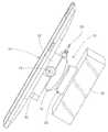
- FIG. 1is a pictorial view of a rotational mount constructed in accordance with a preferred embodiment of the invention
- FIG. 2is a pictorial view of a mounting member portion of the rotational mount that carries an off-plane weight for rotating the mount (and hand-held) into a normal position via the force of gravity;
- FIG. 3is a top view of FIG. 2 ;
- FIG. 4is a view similar to FIG. 3 , but shows the weight removed
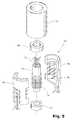
- FIG. 5is an exploded view of a swivel mechanism for conveying power through the rotational mount to a hand-held;
- FIG. 6is a top view of a tablet device supported by the rotational mount
- FIG. 7is a view like FIG. 1 ;
- FIG. 8is a view like FIG. 7 , but from a different angle of view;
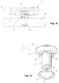
- FIG. 9is a view of the under-side of the rotational mount and illustrates detent springs for adjusting the rotational position of the mounting member, as an option;
- FIG. 10is an exploded view of the rotational mount
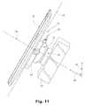
- FIG. 11is a view like FIG. 1 , but shows the axial and planar alignment of the display
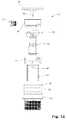
- FIG. 12is an exploded side view
- FIG. 13is an exploded view of the upper part or cap piece of the rotational mount
- FIG. 14is an exploded pictorial view of the detent mechanism.
- FIG. 15is a bottom view of a detent member.
- the rotational mount 10includes an upper body portion, indicated generally by arrow 12 , and a lower body portion that is indicated generally at 14 (see FIG. 9 ).
- the lower body portion 14is generally cylindrical in shape and is sometimes referred to herein as the “lower cylindrical portion 14 .”
- the upper and lower body portions 12 , 14may be manufactured in many different ways but, preferably, they are molded as an integrated piece during the fabrication process.
- the upper body portion 12carries an electronics control board (“ECB”), indicated generally at 16 in exploded view FIG. 10 .
- the ECB 16typically carries the electronics necessary to supply power or security functions to a hand-held device (indicated generally at 18 in the various drawing figures).
- the functions of the ECB 16are generally known in the industry and need not be further described here.
- the usefulness of the inventionrelates to the disclosed mechanical means for rotationally mounting the hand-held 18 to a consumer display stand in a retail environment—which is typically a big-box retailer.
- a retail environmentwhich is typically a big-box retailer.
- a portion of the overall rotational mount assemblyconsists of a base member or base fitting, indicated generally at 22 .
- This fitting 22has a threaded portion 24 that allows it to be fixably mounted to a conventional countertop surface (indicated at 26 in FIGS. 6 , 7 and 8 ).
- the specific way of connecting the base member to the countertop 26can take different forms.
- the base member 22otherwise provides a hollow cylinder for receiving the cylindrical base portion 14 of the rotational mount 10 . It also carries a bearing member 28 and detent member 30 that will be further described later.
- the upper body 12 of the rotational mount 10includes a cap piece 32 that is included as top-most part of the upper body portion 12 .
- the cap piece 32covers the ECB 16 .
- the cap piece 32also has a slotted surface 34 that is shaped to receive a flange 36 of an adaptor member or adaptor plate 38 .
- the flange 36is held in position in cap piece 32 by a lock/release screw 40 or similar means.
- the preferred formis a key lock 41 that allows both security and easy connection or disconnection of adaptor plate 38 from cap piece 32 .
- the adaptor plate 38has two functions. First, it provides a quick-connect, support surface for mounting the hand-held 18 to the rotational mount assembly 10 . Second, it provides a support platform for a weight 42 , in those versions where a weight is used. Referring to FIG. 3 , for example, the weight 42 is connected to adaptor plate 38 on one side thereof. As shown in FIG. 11 , this creates a mass that is off-set relative to an axis, as further described below.
- the lower cylindrical portion 14is free to rotate within the cylindrical opening defined by base member 22 . Freedom of rotation is assisted by the bearing member 28 previously described.
- the rotational mount 10is mounted so that its axis of symmetry (see arrow 44 in FIG. 11 ) is angled relative to the vertical.
- arrow 46indicates a vertical axis
- arrow 48indicates the angle between the axis of symmetry 44 and the vertical axis 46 .
- the axis of symmetry 44is a pivoting axis about which the upper and lower body portions 12 , 14 of the mounting member turn (corresponding to rotation of the hand-held 18 on the display).
- the adaptor plate 38defines the angle of a mounting plane for the hand-held 18 (indicated generally at 50 ) that is normal to the pivoting axis 44 . It is to be appreciated that the plane may occur at different normal locations along axis 44 —which only means it relates to the degree of tilt of the rotational mount 10 . However, the angle of the plane 50 defines a planar orbit for the weight 42 and off-sets the weight 42 a certain distance from the pivoting axis. Therefore, when the hand-held 18 is turned or rotated by the consumer, the weight 42 also turns about the axis 44 to a different rotational position (see arrow 52 in FIG. 3 ).
- the elevated position of the weight 42 relative to what is shown in FIG. 11will cause it to return to the original display position shown in FIGS. 1 and 11 via the force of gravity that is naturally exerted on the weight.
- this gravitational effectwill vary depending on the mounting angle 48 that is selected. As the mounting angle 48 approaches zero (in other words, the pivoting axis 44 approaches the vertical, then the gravitational forces become inadequate to rotationally return the display to its initial position). As the angle 48 approaches ninety degrees (90°), the force of gravity is optimized.
- the rotational bias of the mount 10may be accomplished by other means as an example, with respect to a tablet device, it may be mounted to the adaptor plate 38 so that the center of gravity is offset sufficiently from the pivoting axis 44 so that just the unbalanced weight of the device causes it to return to the original position.
- Hand-heldsneed a power supply when they are on display to consumers. Displays of this type also need a power supply to operate certain security features or functions (e.g., security sensors on the mounting member or security sensors attached to the hand-held itself). Therefore, in order to provide “pass through” power through the rotational mount 10 , an electrical swivel, of the type illustrated in FIG. 5 , is received within the lower cylindrical portion 14 of the mounting member.
- the swivel 54 illustrated in FIG. 5is similar to the one illustrated and described in U.S. Pat. No. 7,744,404, which is incorporated here by reference.
- the swivel 54is adapted to provide a means for utilizing a multiple number of wires to provide power into and through the rotational mount 10 .
- the wiresare indicated at item 70 .
- Each wiremay extend into a cylindrical housing 72 and terminates in a ring contact 74 .
- the ring contact 74is in sliding rotational contact with a similar commutator-type contact 76 in an outer cylinder 78 (shown in halves in FIG. 5 ).
- the inner cylinder 72rotates within the outer cylinder 78 via two bearings 80 , 82 .
- the entire assembly of partsis contained within an outer cylindrical housing 84 which may be received within the lower portion 14 of rotational mount 10 .
- the mount 10can be attached to a countertop surface without significant structure protruding below into the space below the countertop (see, generally arrow 85 ).
- a plurality of spring members 56 , 58may be attached to the underside 60 of the upper mounting member (see FIG. 9 ). These spring members 56 , 58 may releasably catch slots 62 , 64 , 66 , 68 distributed around the detent member 30 .
- FIG. 14illustrates how the spring members 56 , 58 releasably catch different slots in detent member 30 , corresponding to position of rotation.
- FIG. 15shows the generally annular shape of the member 30 .
- the detent member 30provides a means for selecting and holding orientation. It is to be appreciated that the detent member 30 could be used with or without any auto-return function and simply allow the user to rotate the hand-held to discrete positions, and hold the position, until rotated again.
- An advantage of the rotational mount 10 described aboverelates to the freely-swiveling nature of the product 10 .
- the above designallows free rotation of a displayed product around 360° (three hundred sixty degrees) of rotation or more.
- this designpermits a potential purchaser to rotate the device 18 to either the landscape or portrait positions, as desired.
- the adaptor plate 38not only provides a surface or support platform for the hand-held 18 , but also provides the quick-release feature via lock 41 (see FIG. 13 ) previously described. More specifically, the adaptor plate 38 can be sold to a user as a separate component for mounting hand-helds.
- the lock 41enables one hand-held/adaptor plate 38 unit to be swapped quickly on and off the rotational mounting structure. With respect to merchandising uses, this feature provides the ability to have a device securely displayed and powered on the mount 10 . When it is desired to view the device (i.e., a shopper), the lock 41 can be used to quickly remove the device 10 and plate 38 for viewing and using the hand-held off the mount. Afterward, the device can be replaced quickly.
- the invention described hereis well-suited for use in the retail environment, it may be used in other locations where it is desirable to display tablet devices or other kinds of similar devices (e.g., flat-screen displays, etc.).
- tablet devicese.g., flat-screen displays, etc.
- schools, libraries that provide internet access, warehouses, hospitals, or law enforcement agenciesare examples of possible users of the invention described here.
- claims specifically limit scope of the patent rightit is not intended to limit the scope of the patent to retail locations.
- the swivel structure illustrated in FIG. 5is coaxial with, or coaxially aligned with the mount's axis of rotation.
- This featureallows the mount to rotate freely but provide power to the hand-held at all points in time, whether the hand-held is at rest, or being rotated, or even disconnected from the mount (so long as the hand-held's cable remains connected). Placing the swivel above the display surface in the manner disclosed here is believed to provide significant advantages over the prior art.
Landscapes
- Engineering & Computer Science (AREA)
- General Engineering & Computer Science (AREA)
- Mechanical Engineering (AREA)
- Devices For Indicating Variable Information By Combining Individual Elements (AREA)
- Display Racks (AREA)
- Toys (AREA)
Abstract
Description
Claims (2)
Priority Applications (2)
| Application Number | Priority Date | Filing Date | Title |
|---|---|---|---|
| US13/190,376US9220358B2 (en) | 2011-07-25 | 2011-07-25 | Rotational mount for hand-held electronics |
| PCT/US2012/035638WO2013015855A2 (en) | 2011-07-25 | 2012-04-27 | Rotational mount for hand-held electronics |
Applications Claiming Priority (1)
| Application Number | Priority Date | Filing Date | Title |
|---|---|---|---|
| US13/190,376US9220358B2 (en) | 2011-07-25 | 2011-07-25 | Rotational mount for hand-held electronics |
Publications (2)
| Publication Number | Publication Date |
|---|---|
| US20130026322A1 US20130026322A1 (en) | 2013-01-31 |
| US9220358B2true US9220358B2 (en) | 2015-12-29 |
Family
ID=47596442
Family Applications (1)
| Application Number | Title | Priority Date | Filing Date |
|---|---|---|---|
| US13/190,376ActiveUS9220358B2 (en) | 2011-07-25 | 2011-07-25 | Rotational mount for hand-held electronics |
Country Status (2)
| Country | Link |
|---|---|
| US (1) | US9220358B2 (en) |
| WO (1) | WO2013015855A2 (en) |
Cited By (23)
| Publication number | Priority date | Publication date | Assignee | Title |
|---|---|---|---|---|
| US20160064995A1 (en)* | 2014-09-03 | 2016-03-03 | Apple Inc. | Fixtures for displaying products |
| US9786140B2 (en) | 2010-06-21 | 2017-10-10 | Mobile Tech, Inc. | Display for hand-held electronics |
| US9845912B2 (en) | 2015-09-30 | 2017-12-19 | Invue Security Products Inc. | Gang charger, shroud, and dock for portable electronic devices |
| US9892604B2 (en) | 2016-04-15 | 2018-02-13 | Mobile Tech, Inc. | Gateway-based anti-theft security system and method |
| US10101770B2 (en) | 2016-07-29 | 2018-10-16 | Mobile Tech, Inc. | Docking system for portable computing device in an enclosure |
| US10176345B2 (en) | 2012-10-31 | 2019-01-08 | Invue Security Products Inc. | Display stand for a tablet computer |
| USD837632S1 (en) | 2017-07-05 | 2019-01-08 | ACCO Brands Corporation | Lock |
| US10198036B2 (en) | 2012-12-05 | 2019-02-05 | Mobile Tech, Inc. | Docking station for tablet device |
| US10251144B2 (en) | 2015-12-03 | 2019-04-02 | Mobile Tech, Inc. | Location tracking of products and product display assemblies in a wirelessly connected environment |
| US10269202B2 (en) | 2001-12-27 | 2019-04-23 | Mobile Tech, Inc. | Intelligent key system |
| US10373456B2 (en) | 2009-01-10 | 2019-08-06 | Mobile Tech, Inc. | Display for hand-held electronics |
| US20190281715A1 (en)* | 2018-03-08 | 2019-09-12 | ACCO Brands Corporation | Dock for a portable electronic device |
| US10517056B2 (en) | 2015-12-03 | 2019-12-24 | Mobile Tech, Inc. | Electronically connected environment |
| US10593443B1 (en) | 2019-01-24 | 2020-03-17 | Mobile Tech, Inc. | Motion sensing cable for intelligent charging of devices |
| US20200141159A1 (en)* | 2017-05-31 | 2020-05-07 | Invue Security Products Inc. | Systems and methods for locking a sensor to a base |
| US10728868B2 (en) | 2015-12-03 | 2020-07-28 | Mobile Tech, Inc. | Remote monitoring and control over wireless nodes in a wirelessly connected environment |
| USD892123S1 (en) | 2018-07-16 | 2020-08-04 | ACCO Brands Corporation | Dock for a portable electronic device |
| US10907383B2 (en) | 2017-03-01 | 2021-02-02 | ACCO Brands Corporation | Dock for a portable electronic device |
| US20210196058A1 (en)* | 2019-12-30 | 2021-07-01 | Mobile Tech, Inc. | Product merchandising systems with modular puck assemblies for mounting and displaying products |
| US11109335B2 (en) | 2015-12-03 | 2021-08-31 | Mobile Tech, Inc. | Wirelessly connected hybrid environment of different types of wireless nodes |
| US11344140B2 (en) | 2009-01-10 | 2022-05-31 | Mobile Tech, Inc. | Display for hand-held electronics |
| US11540350B2 (en) | 2018-10-25 | 2022-12-27 | Mobile Tech, Inc. | Proxy nodes for expanding the functionality of nodes in a wirelessly connected environment |
| US12267971B2 (en) | 2022-10-17 | 2025-04-01 | Dell Products L.P. | Self-aligning and self-orientating swivel lock mechanism for desktop monitors |
Families Citing this family (28)
| Publication number | Priority date | Publication date | Assignee | Title |
|---|---|---|---|---|
| MX352032B (en) | 2012-02-17 | 2017-11-07 | Valspar Sourcing Inc | Methods and materials for the functionalization of polymers and coatings including functionalized polymer. |
| DE102012217802B4 (en)* | 2012-09-28 | 2018-12-20 | Lufthansa Technik Ag | Attachment system for passenger equipment in an aircraft |
| US9416915B2 (en)* | 2013-03-15 | 2016-08-16 | Lilitab LLC | Configurable mounting system |
| US9416912B2 (en) | 2013-03-15 | 2016-08-16 | Lilitab LLC | Wall mount with configurable stops |
| WO2015050590A2 (en) | 2013-06-11 | 2015-04-09 | Invue Security Products Inc. | Anti-theft device for portable electronic device |
| WO2015054192A1 (en) | 2013-10-08 | 2015-04-16 | Invue Security Products, Inc. | Quick release sensor for merchandise display |
| WO2015096078A1 (en)* | 2013-12-26 | 2015-07-02 | 李慧勤 | Method and apparatus for supporting handheld tablet computer interaction device |
| EP3097245B1 (en) | 2014-01-22 | 2019-10-16 | InVue Security Products, Inc. | Systems and methods for remotely controlling security devices |
| GB2522688A (en)* | 2014-02-03 | 2015-08-05 | Benchmark Fabrications Ltd | Improvements in or relating to display apparatus |
| US9443404B2 (en) | 2014-02-14 | 2016-09-13 | Invue Security Products Inc. | Tethered security system with wireless communication |
| WO2016033037A1 (en) | 2014-08-27 | 2016-03-03 | Invue Security Products Inc. | Systems and methods for locking a sensor to a base |
| GB2530021A (en)* | 2014-09-02 | 2016-03-16 | Spotspot Ltd | Tablet display device security system |
| WO2016034868A1 (en)* | 2014-09-02 | 2016-03-10 | Spotspot Limited | Tablet display device security system |
| US20160127903A1 (en)* | 2014-11-05 | 2016-05-05 | Qualcomm Incorporated | Methods and systems for authentication interoperability |
| US10464780B2 (en) | 2014-12-09 | 2019-11-05 | Mobile Tech, Inc. | Tether lock |
| GB201503987D0 (en) | 2015-03-09 | 2015-04-22 | Tomtom Int Bv | A mount for portable electronic devices |
| GB201504724D0 (en)* | 2015-03-20 | 2015-05-06 | Tom Tom Int Bv | A lock for a rotational mount for portable electronic devices |
| WO2017066114A1 (en) | 2015-10-12 | 2017-04-20 | Invue Security Products Inc. | Recoiler for a merchandise security system |
| WO2018222612A1 (en)* | 2017-05-31 | 2018-12-06 | Mishmosh, Llc | Spinner device and content creation application for a mobile device |
| US10646170B2 (en)* | 2017-12-20 | 2020-05-12 | Drägerwerk AG & Co. KGaA | Rotating docking station |
| CN109041499B (en)* | 2018-08-06 | 2020-10-16 | 郑州泰恩科技有限公司 | Rotatable fixing device for electrical component |
| US11154752B2 (en) | 2018-08-14 | 2021-10-26 | Tonal Systems, Inc. | Collaborative exercise |
| CN109681753B (en)* | 2019-02-01 | 2023-07-04 | 桂林智神信息技术股份有限公司 | Inclined shaft anti-collision handheld stabilizer |
| CN109611675A (en)* | 2019-02-01 | 2019-04-12 | 桂林智神信息技术有限公司 | A kind of hand-held stabilizer of foldable inclined shaft |
| CN109668037B (en)* | 2019-02-01 | 2023-07-04 | 桂林智神信息技术股份有限公司 | Foldable handheld stabilizer |
| US11819736B2 (en) | 2019-11-01 | 2023-11-21 | Tonal Systems, Inc. | Modular exercise machine |
| CN117824558B (en)* | 2024-03-06 | 2024-05-31 | 成都凯天电子股份有限公司 | A mobile mechanism for high and low temperature testing and a displacement detection method |
| US12428878B1 (en) | 2024-05-31 | 2025-09-30 | Invue Security Products Inc. | Security device |
Citations (5)
| Publication number | Priority date | Publication date | Assignee | Title |
|---|---|---|---|---|
| US4898493A (en)* | 1989-03-16 | 1990-02-06 | Karl Blankenburg | Method and apparatus for assembling parts |
| US5176465A (en)* | 1990-08-27 | 1993-01-05 | Holsted Carl A | Device for interlocking separate component housing structures |
| US7744404B1 (en)* | 2009-11-03 | 2010-06-29 | Merchandising Technologies, Inc. | Cable management system for product display |
| US20120217371A1 (en)* | 2011-02-24 | 2012-08-30 | Invue Security Products Inc. | Merchandise display security tether including releasable adhesive |
| US20120286118A1 (en)* | 2011-03-15 | 2012-11-15 | David Richards | Hands-free systems for attaching a personal electronic device and methods for using the same |
Family Cites Families (4)
| Publication number | Priority date | Publication date | Assignee | Title |
|---|---|---|---|---|
| US6189842B1 (en)* | 1999-06-21 | 2001-02-20 | Palo Alto Design Group | Tilt and swivel adjustment of flat panel display having detents for landscape and portrait positions and kickout for preventing contact between flat panel display and base |
| US6659382B2 (en)* | 2001-07-10 | 2003-12-09 | Vira Manufacturing, Inc. | Security device for display of hand held items |
| US7475452B2 (en)* | 2003-05-21 | 2009-01-13 | Premier Image Technology Corporation | Swivel structure for information product |
| CA2658438C (en)* | 2008-03-17 | 2018-05-01 | Compucage International Inc. | Security mount for displaying handheld device |
- 2011
- 2011-07-25USUS13/190,376patent/US9220358B2/enactiveActive
- 2012
- 2012-04-27WOPCT/US2012/035638patent/WO2013015855A2/enactiveApplication Filing
Patent Citations (5)
| Publication number | Priority date | Publication date | Assignee | Title |
|---|---|---|---|---|
| US4898493A (en)* | 1989-03-16 | 1990-02-06 | Karl Blankenburg | Method and apparatus for assembling parts |
| US5176465A (en)* | 1990-08-27 | 1993-01-05 | Holsted Carl A | Device for interlocking separate component housing structures |
| US7744404B1 (en)* | 2009-11-03 | 2010-06-29 | Merchandising Technologies, Inc. | Cable management system for product display |
| US20120217371A1 (en)* | 2011-02-24 | 2012-08-30 | Invue Security Products Inc. | Merchandise display security tether including releasable adhesive |
| US20120286118A1 (en)* | 2011-03-15 | 2012-11-15 | David Richards | Hands-free systems for attaching a personal electronic device and methods for using the same |
Cited By (50)
| Publication number | Priority date | Publication date | Assignee | Title |
|---|---|---|---|---|
| US10269202B2 (en) | 2001-12-27 | 2019-04-23 | Mobile Tech, Inc. | Intelligent key system |
| US10453291B2 (en) | 2001-12-27 | 2019-10-22 | Mobile Tech, Inc. | Intelligent key system |
| US10984625B2 (en) | 2001-12-27 | 2021-04-20 | Mobile Tech, Inc. | Intelligent key system |
| US10373456B2 (en) | 2009-01-10 | 2019-08-06 | Mobile Tech, Inc. | Display for hand-held electronics |
| US10977914B2 (en) | 2009-01-10 | 2021-04-13 | Mobile Tech, Inc. | Display for hand-held electronics |
| US11344140B2 (en) | 2009-01-10 | 2022-05-31 | Mobile Tech, Inc. | Display for hand-held electronics |
| US10026281B2 (en) | 2009-01-10 | 2018-07-17 | Mobile Tech, Inc. | Display for hand-held electronics |
| US10217338B2 (en) | 2010-06-21 | 2019-02-26 | Mobile Tech, Inc. | Display for hand-held electronics |
| US9786140B2 (en) | 2010-06-21 | 2017-10-10 | Mobile Tech, Inc. | Display for hand-held electronics |
| US10083583B2 (en) | 2010-06-21 | 2018-09-25 | Mobile Tech, Inc. | Display for hand-held electronics |
| US10861300B2 (en) | 2010-06-21 | 2020-12-08 | Mobile Tech, Inc. | Display for hand-held electronics |
| US10176345B2 (en) | 2012-10-31 | 2019-01-08 | Invue Security Products Inc. | Display stand for a tablet computer |
| US10782735B2 (en) | 2012-12-05 | 2020-09-22 | Mobile Tech, Inc. | Docking station for tablet device |
| US10198036B2 (en) | 2012-12-05 | 2019-02-05 | Mobile Tech, Inc. | Docking station for tablet device |
| US10198035B2 (en) | 2012-12-05 | 2019-02-05 | Mobile Tech, Inc. | Docking station for tablet device |
| US9954386B2 (en)* | 2014-09-03 | 2018-04-24 | Apple Inc. | Fixtures for displaying products |
| US20160064995A1 (en)* | 2014-09-03 | 2016-03-03 | Apple Inc. | Fixtures for displaying products |
| US11994250B2 (en) | 2015-09-30 | 2024-05-28 | Invue Security Products Inc. | Gang charger, shroud, and dock for portable electronic devices |
| US9845912B2 (en) | 2015-09-30 | 2017-12-19 | Invue Security Products Inc. | Gang charger, shroud, and dock for portable electronic devices |
| US10674466B2 (en) | 2015-12-03 | 2020-06-02 | Mobile Tech, Inc. | Location tracking of products and product display assemblies in a wirelessly connected environment |
| US10728868B2 (en) | 2015-12-03 | 2020-07-28 | Mobile Tech, Inc. | Remote monitoring and control over wireless nodes in a wirelessly connected environment |
| US10517056B2 (en) | 2015-12-03 | 2019-12-24 | Mobile Tech, Inc. | Electronically connected environment |
| US10524220B2 (en) | 2015-12-03 | 2019-12-31 | Mobile Tech, Inc. | Location tracking of products and product display assemblies in a wirelessly connected environment |
| US10667227B2 (en) | 2015-12-03 | 2020-05-26 | Mobile Tech, Inc. | Electronically connected environment |
| US10251144B2 (en) | 2015-12-03 | 2019-04-02 | Mobile Tech, Inc. | Location tracking of products and product display assemblies in a wirelessly connected environment |
| US11109335B2 (en) | 2015-12-03 | 2021-08-31 | Mobile Tech, Inc. | Wirelessly connected hybrid environment of different types of wireless nodes |
| US11315398B2 (en) | 2016-04-15 | 2022-04-26 | Mobile Tech, Inc. | Gateway-based anti-theft security system and method |
| US10540872B2 (en) | 2016-04-15 | 2020-01-21 | Mobile Tech, Inc. | Gateway-based anti-theft security system and method |
| US10157522B2 (en) | 2016-04-15 | 2018-12-18 | Mobile Tech, Inc. | Authorization control for an anti-theft security system |
| US10776473B2 (en) | 2016-04-15 | 2020-09-15 | Mobile Tech, Inc. | Authorization control for an anti-theft security system |
| US9959432B2 (en) | 2016-04-15 | 2018-05-01 | Mobile Tech, Inc. | Authorization control for an anti-theft security system |
| US9892604B2 (en) | 2016-04-15 | 2018-02-13 | Mobile Tech, Inc. | Gateway-based anti-theft security system and method |
| US10281955B2 (en) | 2016-07-29 | 2019-05-07 | Mobile Tech, Inc. | Docking system for portable computing device |
| US10101770B2 (en) | 2016-07-29 | 2018-10-16 | Mobile Tech, Inc. | Docking system for portable computing device in an enclosure |
| US10754381B2 (en) | 2016-07-29 | 2020-08-25 | Mobile Tech, Inc. | Docking system for portable computing device |
| US10907383B2 (en) | 2017-03-01 | 2021-02-02 | ACCO Brands Corporation | Dock for a portable electronic device |
| US11939796B2 (en) | 2017-03-01 | 2024-03-26 | ACCO Brands Corporation | Dock for a portable electronic device |
| US20200141159A1 (en)* | 2017-05-31 | 2020-05-07 | Invue Security Products Inc. | Systems and methods for locking a sensor to a base |
| US12134918B2 (en) | 2017-05-31 | 2024-11-05 | Invue Security Products Inc. | Systems and methods for locking a sensor to a base |
| US11236528B2 (en)* | 2017-05-31 | 2022-02-01 | Invue Security Products Inc. | Systems and methods for locking a sensor to a base |
| USD837632S1 (en) | 2017-07-05 | 2019-01-08 | ACCO Brands Corporation | Lock |
| US10917986B2 (en)* | 2018-03-08 | 2021-02-09 | ACCO Brands Corporation | Dock for a portable electronic device |
| US20190281715A1 (en)* | 2018-03-08 | 2019-09-12 | ACCO Brands Corporation | Dock for a portable electronic device |
| US11770911B2 (en)* | 2018-03-08 | 2023-09-26 | ACCO Brands Corporation | Dock for a portable electronic device |
| USD892123S1 (en) | 2018-07-16 | 2020-08-04 | ACCO Brands Corporation | Dock for a portable electronic device |
| US11540350B2 (en) | 2018-10-25 | 2022-12-27 | Mobile Tech, Inc. | Proxy nodes for expanding the functionality of nodes in a wirelessly connected environment |
| US10593443B1 (en) | 2019-01-24 | 2020-03-17 | Mobile Tech, Inc. | Motion sensing cable for intelligent charging of devices |
| US10614682B1 (en) | 2019-01-24 | 2020-04-07 | Mobile Tech, Inc. | Motion sensing cable for tracking customer interaction with devices |
| US20210196058A1 (en)* | 2019-12-30 | 2021-07-01 | Mobile Tech, Inc. | Product merchandising systems with modular puck assemblies for mounting and displaying products |
| US12267971B2 (en) | 2022-10-17 | 2025-04-01 | Dell Products L.P. | Self-aligning and self-orientating swivel lock mechanism for desktop monitors |
Also Published As
| Publication number | Publication date |
|---|---|
| WO2013015855A3 (en) | 2014-05-08 |
| WO2013015855A2 (en) | 2013-01-31 |
| US20130026322A1 (en) | 2013-01-31 |
Similar Documents
| Publication | Publication Date | Title |
|---|---|---|
| US9220358B2 (en) | Rotational mount for hand-held electronics | |
| US9599276B2 (en) | Swivel mount | |
| US11162527B2 (en) | Ball and socket joint for device enclosure | |
| CN101034593B (en) | Display device | |
| US9746128B2 (en) | Adjustable dual-screen monitor stand | |
| US8608119B2 (en) | Display stand | |
| US8991775B2 (en) | Kiosks for electronic devices | |
| KR101849112B1 (en) | Multifunctional magnetic support appratus for adhering product | |
| US9891666B2 (en) | Apparatus with twistable electronics dock and rotatable connecting port having a plurality of heads | |
| US9062811B2 (en) | Support structure and electronic device using same | |
| US20140226298A1 (en) | Apparatus for securely displaying an electronic device | |
| US20130009032A1 (en) | Support stand with flexible connectors for objects, portable electronic devices, musical equipment, clipboards, etc., using standard microphone holder, horizontal surface or wall mount | |
| US20090261216A1 (en) | Support mechanism and portable electronic device using the same | |
| US9254029B2 (en) | Swivel base for a training aid | |
| JP2009521300A (en) | Display with automatic orientation mounting area | |
| TW200906271A (en) | Rotatable support mechanism and electronic device using the same | |
| TW201030266A (en) | Multiple arm articulating mounting system | |
| US9844159B1 (en) | Handheld mount for portable electronic devices | |
| US20130168275A1 (en) | Electronic tablet transport and retaining apparatus | |
| US20230211738A1 (en) | Display case for mobile devices | |
| US20140175116A1 (en) | Dispensing assembly in vending machine | |
| KR101428051B1 (en) | Dual monitor | |
| TW200839674A (en) | Adjustable apparatus for adjusting positions and viewing angle of displaying panel and displayer applied with the same | |
| CN211010562U (en) | Electronic device and rotating structure | |
| KR200479463Y1 (en) | Depository for Portable Information and Communication Appliance |
Legal Events
| Date | Code | Title | Description |
|---|---|---|---|
| AS | Assignment | Owner name:MERCHANDISING TECHNOLOGIES, INC., OREGON Free format text:ASSIGNMENT OF ASSIGNORS INTEREST;ASSIGNORS:NIDEROST, DONALD;WHEELER, WADE;PETERS, RON;AND OTHERS;SIGNING DATES FROM 20110727 TO 20110728;REEL/FRAME:026755/0850 | |
| AS | Assignment | Owner name:FIFTH THIRD BANK, OHIO Free format text:SECURITY AGREEMENT;ASSIGNOR:MOBILE TECH, INC.;REEL/FRAME:030937/0416 Effective date:20130801 | |
| AS | Assignment | Owner name:MOBILE TECH, INC., OREGON Free format text:ASSIGNMENT OF ASSIGNORS INTEREST;ASSIGNOR:MERCHANDISING TECHNOLOGIES, INC.;REEL/FRAME:030937/0993 Effective date:20130801 | |
| AS | Assignment | Owner name:CAPITALSOUTH PARTNERS SBIC FUND III, L.P., NORTH CAROLINA Free format text:SECURITY AGREEMENT;ASSIGNOR:MOBILE TECH, INC.;REEL/FRAME:031005/0148 Effective date:20130801 Owner name:CAPITALSOUTH PARTNERS SBIC FUND III, L.P., NORTH C Free format text:SECURITY AGREEMENT;ASSIGNOR:MOBILE TECH, INC.;REEL/FRAME:031005/0148 Effective date:20130801 | |
| STCF | Information on status: patent grant | Free format text:PATENTED CASE | |
| AS | Assignment | Owner name:PNC BANK, NATIONAL ASSOCIATION, PENNSYLVANIA Free format text:SECURITY INTEREST;ASSIGNOR:MOBILE TECH, INC.;REEL/FRAME:039370/0989 Effective date:20160805 | |
| AS | Assignment | Owner name:MOBILE TECH, INC., OREGON Free format text:RELEASE OF SECURITY INTEREST RECORDED AT R/FS 030937/0416 AND 032608/0623;ASSIGNOR:FIRTH THIRD BANK;REEL/FRAME:039752/0495 Effective date:20160805 | |
| MAFP | Maintenance fee payment | Free format text:PAYMENT OF MAINTENANCE FEE, 4TH YR, SMALL ENTITY (ORIGINAL EVENT CODE: M2551); ENTITY STATUS OF PATENT OWNER: SMALL ENTITY Year of fee payment:4 | |
| FEPP | Fee payment procedure | Free format text:7.5 YR SURCHARGE - LATE PMT W/IN 6 MO, SMALL ENTITY (ORIGINAL EVENT CODE: M2555); ENTITY STATUS OF PATENT OWNER: SMALL ENTITY | |
| MAFP | Maintenance fee payment | Free format text:PAYMENT OF MAINTENANCE FEE, 8TH YR, SMALL ENTITY (ORIGINAL EVENT CODE: M2552); ENTITY STATUS OF PATENT OWNER: SMALL ENTITY Year of fee payment:8 |