US9218116B2 - Touch interaction with a curved display - Google Patents
Touch interaction with a curved displayDownload PDFInfo
- Publication number
- US9218116B2 US9218116B2US12/344,377US34437708AUS9218116B2US 9218116 B2US9218116 B2US 9218116B2US 34437708 AUS34437708 AUS 34437708AUS 9218116 B2US9218116 B2US 9218116B2
- Authority
- US
- United States
- Prior art keywords
- curved display
- contacts
- threshold
- interaction unit
- interaction
- Prior art date
- Legal status (The legal status is an assumption and is not a legal conclusion. Google has not performed a legal analysis and makes no representation as to the accuracy of the status listed.)
- Expired - Fee Related, expires
Links
Images


Classifications
- G—PHYSICS
- G06—COMPUTING OR CALCULATING; COUNTING
- G06F—ELECTRIC DIGITAL DATA PROCESSING
- G06F3/00—Input arrangements for transferring data to be processed into a form capable of being handled by the computer; Output arrangements for transferring data from processing unit to output unit, e.g. interface arrangements
- G06F3/01—Input arrangements or combined input and output arrangements for interaction between user and computer
- G06F3/048—Interaction techniques based on graphical user interfaces [GUI]
- G06F3/0484—Interaction techniques based on graphical user interfaces [GUI] for the control of specific functions or operations, e.g. selecting or manipulating an object, an image or a displayed text element, setting a parameter value or selecting a range
- G06F3/0486—Drag-and-drop
- G—PHYSICS
- G06—COMPUTING OR CALCULATING; COUNTING
- G06F—ELECTRIC DIGITAL DATA PROCESSING
- G06F3/00—Input arrangements for transferring data to be processed into a form capable of being handled by the computer; Output arrangements for transferring data from processing unit to output unit, e.g. interface arrangements
- G06F3/01—Input arrangements or combined input and output arrangements for interaction between user and computer
- G06F3/03—Arrangements for converting the position or the displacement of a member into a coded form
- G06F3/041—Digitisers, e.g. for touch screens or touch pads, characterised by the transducing means
- G06F3/042—Digitisers, e.g. for touch screens or touch pads, characterised by the transducing means by opto-electronic means
- G—PHYSICS
- G06—COMPUTING OR CALCULATING; COUNTING
- G06F—ELECTRIC DIGITAL DATA PROCESSING
- G06F3/00—Input arrangements for transferring data to be processed into a form capable of being handled by the computer; Output arrangements for transferring data from processing unit to output unit, e.g. interface arrangements
- G06F3/01—Input arrangements or combined input and output arrangements for interaction between user and computer
- G06F3/048—Interaction techniques based on graphical user interfaces [GUI]
- G06F3/0487—Interaction techniques based on graphical user interfaces [GUI] using specific features provided by the input device, e.g. functions controlled by the rotation of a mouse with dual sensing arrangements, or of the nature of the input device, e.g. tap gestures based on pressure sensed by a digitiser
- G06F3/0488—Interaction techniques based on graphical user interfaces [GUI] using specific features provided by the input device, e.g. functions controlled by the rotation of a mouse with dual sensing arrangements, or of the nature of the input device, e.g. tap gestures based on pressure sensed by a digitiser using a touch-screen or digitiser, e.g. input of commands through traced gestures
- G06F3/04883—Interaction techniques based on graphical user interfaces [GUI] using specific features provided by the input device, e.g. functions controlled by the rotation of a mouse with dual sensing arrangements, or of the nature of the input device, e.g. tap gestures based on pressure sensed by a digitiser using a touch-screen or digitiser, e.g. input of commands through traced gestures for inputting data by handwriting, e.g. gesture or text
- G—PHYSICS
- G06—COMPUTING OR CALCULATING; COUNTING
- G06F—ELECTRIC DIGITAL DATA PROCESSING
- G06F2203/00—Indexing scheme relating to G06F3/00 - G06F3/048
- G06F2203/048—Indexing scheme relating to G06F3/048
- G06F2203/04808—Several contacts: gestures triggering a specific function, e.g. scrolling, zooming, right-click, when the user establishes several contacts with the surface simultaneously; e.g. using several fingers or a combination of fingers and pen
Definitions
- GUIgraphical user interface
- a usermanipulates the device to move a pointer around a display screen.
- functionalityis activated with the device by clicking on a given screen position, such as on an icon or a button.
- touch screen interfaceswere developed. With a touch screen, a user may activate functionality by physically touching and/or pressing on a given screen position. However, such touch screens were still flat.
- spherical displaysof one kind or another have been developed. These spherical displays are especially employed in promotional environments or for the display of three-dimensional (3D) data. Spherical displays can offer an unobstructed 360° field-of-view to multiple users. This enables viewers to explore different perspectives of the displayed data by physically moving around the display.
- Viewerscan use the spherical nature of the display, their physical body position and orientation, and additional cues from the surrounding environment to aid them in spatially finding and understanding the data that is being displayed on a spherical surface.
- the characteristics of a display in a spherical form factorcan afford interesting usage scenarios that go beyond what is possible with the more prevalent flat displays.
- Spherical displaysalso offer diverse interaction challenges.
- conventional user interface (UI) technologiesare rooted in traditional flat displays. As a result, conventional UI technologies fail to take advantage of the interesting usage scenarios and fail to address the diverse interaction challenges of curved displays.
- Touch interaction with a curved displayis enabled through various user interface (UI) features.
- UIuser interface
- a curved displayis monitored to detect a touch input. If a touch input is detected based on the act of monitoring, then one or more locations of the touch input are determined. Responsive to the determined one or more locations of the touch input, at least one user UI feature is implemented.
- Example UI featuresinclude an orb-like invocation gesture feature, a rotation-based dragging feature, a send-to-dark-side interaction feature, and an object representation and manipulation by proxy representation feature.
- an orb-like invocation gesture featurea presentation of a menu or a switching of tasks is invoked by making two relatively larger touch contacts in a substantially symmetrical position around a fixed point, such as the top of a spherical curved display.
- a rotation-based dragging featureobjects that are dragged across a curved display are moved using a rotation that represents an arc defined by the dragging motion.
- a relatively larger contact on an object for a predefined temporal thresholdprecipitates a warping of the object from one side of a curved display to another.
- a proxy representationis displayed for a corresponding object on the other side of a curved display. Manipulations to the proxy representation are reflected in the corresponding object.
- FIG. 1illustrates an example user interaction environment for a curved display.
- FIG. 2depicts a straightforward approach to implementing a dragging operation with a display that may be manipulated by touch.
- FIG. 3is a block diagram of an example device having a curved display and the capability to enable interaction responsive to touch input via an interaction unit.
- FIG. 4is a flow diagram that illustrates an example of a method for touch interaction with a curved display.
- FIG. 5is a block diagram of an interaction unit having four example units: an orb-like invocation gesture unit, a rotation-based dragging unit, a send-to-dark-side interaction unit, and an object representation and manipulation by proxy representation unit.
- FIG. 6Aillustrates an example mechanism for an orb-like invocation gesture unit.
- FIG. 6Bis a flow diagram that illustrates an example of a method for an orb-like invocation gesture technique.
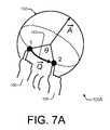
- FIG. 7Aillustrates an example mechanism for a rotation-based dragging unit.
- FIG. 7Bis a flow diagram that illustrates an example of a method for a rotation-based dragging technique.
- FIG. 8Aillustrates an example mechanism for a send-to-dark-side interaction unit.
- FIG. 8Bis a flow diagram that illustrates an example of a method for a send-to-dark-side interaction technique.
- FIG. 9Aillustrates an example mechanism for an object representation and manipulation by proxy representation unit.
- FIG. 9Bis a flow diagram that illustrates an example of a method for an object representation and manipulation by proxy representation technique.
- FIG. 10is a block diagram illustrating example devices that may be used to implement embodiments for touch interaction with a curved display.
- FIG. 1illustrates an example UI environment 100 for a curved display 102 .
- UI environment 100includes curved display 102 , an object 104 , and multiple members 106 . More specifically, object 104 is presented on curved display 102 . Two members 106 a and 106 b are shown interacting with curved display 102 . The elliptical shape formed from the dotted line indicates that curved display 102 is three-dimensional.
- enabling user interaction on a curved surfaceinvolves the implementation of basic operations such as selection, dragging, rotation, scaling, and so forth. It may further entail providing support for browsing, task switching, and so forth.
- Each objecte.g., photo, video, etc.
- Each objectcan be independently dragged, rotated, and scaled.
- selection of an objectis implicitly triggered by a touch contact that lands on that object. Touch contacts that land on a video object act as a simple playback toggle—it starts the video playback if the video is paused or stops it if the video is running.
- the displayed elements of curved display 102may be manipulated by members 106 .
- Members 106may be a finger or fingers, a hand or hands, a palm or palms, combinations thereof, and so forth.
- Members 106may belong to the same or to different users.
- object 104is shown as a photo or video, objects 104 may be any displayable element (e.g., web pages, textual documents, spreadsheets, raw data or images, combinations thereof, etc.).
- curved display 102is shown as a sphere, it may alternatively be cylindrical, cuboidal, hemispherical, a combination thereof, and so forth.
- curved displays 102 that are illustrated in the drawingsare spheres and are frequently described herein as being spherical, this is by way of example only. It should be understood that the principles and interactions explained herein are applicable to curved displays 102 generally.
- User interactions 108may include, for example, many different types of touches. The touches may vary by size, duration, location, movement, combinations thereof, and so forth. User interactions 108 may also include gestures, postures, combinations thereof, and so forth. These user interactions 108 may be defined and/or combined to enable different UI approaches 110 , such as UI techniques and mechanisms. Different UI approaches 110 are described herein to take advantage of the properties of curved displays and/or to accommodate unusual characteristics of curved displays. Such properties and characteristics are described below.
- Non-flat interactive displayshave several properties that differ from their flat counterparts. Different interaction concepts may therefore be applied to curved displays.
- curved displayshave the following three example inherent difficulties.
- First, the display surfaceis not a traditional Euclidian space, and it does not easily map into a flat space. This makes traditional flat interactions, such as a 2D translation, difficult. This first difficulty is described in greater detail herein below with particular reference to FIG. 2 .
- Second, the movement of visual elements around the surfacecan result in potentially awkward orientations for the displaced elements, including with regard to the viewpoints of multiple collaborators who may surround the curved display.
- a usermay be limited to seeing at most one hemisphere because data or other objects that are located on the other side (e.g., the opposite hemisphere) are currently invisible to the user due to the curvature of the display.
- Curved displaysintrinsically possess a number of other differentiating characteristics. For example, they do not have a natural “master user” position. Each user may instead be afforded an ceremoniitarian user experience. Also, the content that is visible to each user changes with their height and position. Moreover, as a user changes their height and position, a spherical display can seem to smoothly transition between a vertical and a horizontal surface.
- a usermoves around a curved display, it appears to be borderless, yet it is actually finite. It also becomes apparent that there are no natural orientation landmarks. In practice, however, the top (or “north pole” for a spherical display) may be perceived to be the strongest natural landmark for a curved display. Additionally, because a user is typically limited to seeing at most one-half of a curved display, other areas of the curved display offer pseudo-privacy. In other words, what one user is viewing in one hemisphere is relatively obstructed from the vision of other users that are viewing the opposite hemisphere.
- a set of multi-touch interaction mechanisms (or features) and techniques for curved displays that facilitate interaction and collaboration around curved displaysare introduced below following the description of FIG. 2 .
- Four example embodimentsare described herein below with particular reference to the units of FIG. 5 . These four example embodiments are described in greater detail with particular reference to FIGS. 6 A/ 6 B, 7 A/ 7 B, 8 A/ 8 B, and 9 A/ 9 B, respectively.
- FIG. 2depicts a straightforward approach 200 to implementing a dragging operation with a display that may be manipulated by touch.
- approach 200includes a member 106 , two points 1 and 2 , and a vector ⁇ right arrow over (V) ⁇ .
- Member 106moves from point 1 to point 2 while touching a display. This movement defines a vector ⁇ right arrow over (V) ⁇ .
- the vector ⁇ right arrow over (V) ⁇has a combined dimensionality along two or three orthogonal components. It may also be thought of as having both a direction and a magnitude component.
- a vector ⁇ right arrow over (V) ⁇may be used to translate an object in Euclidean space, such as over a flat display.
- Enabling a user to drag an object around a spherical displayis not as straightforward as it may seem at first.
- a difficultyis that the curved geometry of the spherical surface is drastically different from 2D flat space.
- movementmay be represented by a displacement vector ⁇ right arrow over (V) ⁇ that encapsulates the direction and magnitude of the movement in a particular line.
- Vdisplacement vector
- a spherical surfaceis not a Euclidian space. There are no straight lines on a sphere as so-called “lines” are actually curves, which are more accurately represented as arcs. While in some cases Euclidean geometry might offer a reasonable local approximation, representing displacement on a sphere with vectors ultimately leads to problematic behaviors.
- curved displaysentail a number of properties that create UI difficulties. These properties include having a non-Euclidian space and having areas that may be obstructed from the view of a given user. Furthermore, curved displays may have areas that are unreachable by a user without the user moving around the display to a different position.
- certain example embodimentsentail the implementation of UI approaches that are tailored to curved displays.
- interaction techniques and user interface mechanismscan facilitate the multi-touch manipulation of displayed objects on curved surfaces. These approaches can enable easier collaboration between multiple users by exploiting the different characteristics of curved surfaces.
- An example UI approachinvolves an orb-like invocation gesture.
- a mode switch or a menuis invoked via a specific bimanual hand posture on the top of the curved display.
- the postureis relatively easy to remember, but relatively hard to invoke inadvertently.
- Another example UI approachinvolves facilitating the dragging of objects along a curved surface.
- a rotation-oriented movementis used as the basic unit of dragging, instead of a translation-oriented displacement vector.
- Yet another example UI approachinvolves a send-to-dark-side interaction.
- a usercan “instantaneously” warp/move an object to the opposite side of a curved display.
- Yet another example UI approachinvolves a shadow object representation and manipulation.
- a useris empowered to effectively “see” and manipulate objects on the other side of a curved display (e.g., objects that are otherwise at least partially invisible) using their proxy representation on a hemisphere that is closer to the user.
- the proxy representationmay be a shadow or outline representation, for instance, of the actual object.
- FIG. 3is a block diagram of an example device 300 having a curved display 102 and the capability to enable interaction responsive to touch input via an interaction unit 302 .
- device 300includes curved display 102 , a display component 304 , and a processing unit 310 .
- Display component 304includes a projection component 306 and a detection component 308 .
- Processing unit 310includes a projection unit 312 , a detection unit 314 , and interaction unit 302 .
- a member 106is shown in proximity to curved display 102 .
- curved display 102may be any type of curved display having an interior and an exterior. Curved display 102 may have a diffuse surface for displaying images projected thereon by projection component 306 . Examples for curved display 102 include, but are not limited to, spheres, cylinders, hemispheres, cuboids, combinations thereof, and so forth. In example implementations, curved display 102 at least partially encloses a space. It may also completely enclose a space, such as with a complete sphere or cuboid or a “solid” cylinder. Alternatively, it may partially enclose a space, such as with an open hemisphere or a cylinder with an open flat end. Other alternatives may also be implemented.
- display component 304is at least primarily a hardware component of device 300 .
- Projection component 306enables a projection of images onto curved display 102 (e.g., from the interior of the curved display). It may be realized, for instance, as a projector of light in the visible spectrum and a wide-angle lens.
- Detection component 308enables one or more touch contacts by at least one member 106 on curved display 102 to be detected.
- Member(s) 106may be, by way of example but not limitation, a finger, multiple fingers, a hand, multiple hands, one or more palms, some combination thereof, and so forth. Members 106 may originate from the same person or from different people.
- Detection component 308is adapted to detect when and where member 106 touches/contacts curved display 102 .
- Detection component 308may be realized, for instance, as a set of infrared (IR)-tuned light emitting diodes (LEDs) that emanate into and/or towards curved display 102 along with an IR detector that detects when the IR light is reflected back from curved display 102 .
- the IR lightmay be reflected back from curved display 102 to detection component 308 by, for example, a touch of member 106 .
- Detection component 308is adapted to detect the location or locations of the touch or touches by member 106 on curved display 102 .
- detection component 308may be capable of detecting a size of the touch (e.g., a finger versus a palm) by member 106 . These detections may be provided to detection unit 314 of processing unit 310 for analysis to facilitate interaction with device 300 via touches on curved display 102 .
- Processing unit 310may be realized, for example, with one or more processors and at least one memory.
- detection unit 314provides locations and/or sizes of detected touch contacts to interaction unit 302 .
- Interaction unit 302is to enable UI interactions with device 300 via curved display 102 .
- detection unit 314detects whether a finger-sized or a palm-sized touch input is occurring at curved display 102 by detecting a size of the touch input and comparing the size of the detected touch input to a predetermined size threshold.
- Interaction unit 302can then implement a UI feature based on whether the detected touch input is finger-sized or palm-sized.
- Interaction unit 302sends display commands for manipulating UI elements and other display items to projection unit 312 .
- Projection unit 312may control what images are projected onto curved display 102 by projection component 306 .
- interaction unit 302may implement one or more of the embodiments described further herein. These embodiments are described (i) generally by way of an example flow diagram with reference to FIG. 4 and (ii) more specifically with reference to FIG. 5 . Example embodiments are described in greater detail with reference to FIGS. 6A-9B .
- FIG. 4is a flow diagram 400 that illustrates an example of a method for touch interaction with a curved display.
- Flow diagram 400includes four blocks 402 - 408 .
- Implementations of flow diagram 400may be realized, for example, as processor-executable instructions and/or as part of processing unit 310 (of FIG. 3 ), including at least partially by a projection unit 312 , a detection unit 314 , and/or an interaction unit 302 .
- Example embodiments for implementing flow diagram 400are described below with reference to the elements of FIGS. 1 and 3 .
- flow diagram 400(and those of the other flow diagrams) that are described herein may be performed in many different environments and with a variety of different devices, such as by one or more processing devices (e.g., of FIG. 10 ).
- processing devicese.g., of FIG. 10
- the order in which the methods are describedis not intended to be construed as a limitation, and any number of the described blocks can be combined, augmented, rearranged, and/or omitted to implement a respective method, or an alternative method that is equivalent thereto.
- specific elements of certain other FIGS.are referenced in the description of the flow diagrams, the methods thereof may be performed with alternative elements.
- a curved displayis monitored for touch input.
- a curved display 102may be monitored by detection component 308 and/or detection unit 314 for touch input.
- detection unit 314may monitor curved display 102 to detect touch input by one or more members 106 . If no touch is detected, then the monitoring continues (at block 402 ).
- touch inputis detected (at block 404 )
- one or more locations of the touch inputare determined. For example, the location(s) of touch input(s) by member(s) 106 on curved display 102 may be determined. These determinations may entail ascertaining a size of the touch input (e.g., finger versus palm), ascertaining a number of touch inputs (e.g., number of fingers, palms, people, etc.) on the curved display, tracking movement(s) of the touch input, monitoring a duration of a touch input, some combination thereof, and so forth.
- a size of the touch inpute.g., finger versus palm
- a number of touch inputse.g., number of fingers, palms, people, etc.
- At block 408at least one UI feature is implemented responsive to the one or more locations of touch input.
- at least one UI approache.g., mechanism and/or technique
- interaction unit 302responsive to the determined location(s) of the touch input.
- Example UI approachesare described generally herein below with particular reference to FIG. 5 . Additional example embodiments are described more specifically with reference to FIGS. 6A-9B .
- Example UI approachesinclude those that involve moving displayed objects, those that involve detecting a palm-sized touch (e.g., as differentiated from a finger-sized touch) and responding accordingly, combinations thereof, and so forth.
- FIG. 5is a block diagram of example units 502 - 508 of an interaction unit 302 (of FIG. 3 ).
- interaction unit 302includes an orb-like invocation gesture unit 502 , a rotation-based dragging unit 504 , a send-to-dark-side interaction unit 506 , and an object representation and manipulation by proxy representation unit 508 .
- Each of these unitsis capable of implementing at least one UI feature.
- These units 502 - 508 of interaction unit 302may be organized into categories. For example, rotation-based dragging unit 504 and object representation and manipulation by proxy representation unit 508 may be categorized as involving the movement of displayed objects around a curved display. Also, orb-like invocation gesture unit 502 and send-to-dark-side interaction unit 506 may be categorized as involving the detection of palm-sized touches with appropriate UI responses.
- send-to-dark-side interaction unit 506may also be categorized as involving the movement of displayed objects around a curved display.
- a UI featureis implemented by orb-like invocation gesture unit 502 .
- the UI featuremay be a menu presentation, a mode switch, and so forth.
- the menumay be circular, semi-circular, and so forth. Example mechanisms and techniques for orb-like invocation gesture unit 502 are described further herein below with particular reference to FIGS. 6A and 6B .
- movements of objects on curved display 102are accomplished, at least in part, using a rotation. Movements of displayed objects are manifested as rotations about the center of the curved display (e.g., around the center of a sphere). For instance, an axis may be determined, and an angle about the axis may define the movement of the displayed object.
- Rotation-based dragging unit 504may also be used to facilitate object movements in conjunction with other embodiments. Example mechanisms and techniques for rotation-based dragging unit 504 are described further herein below with particular reference to FIGS. 7A and 7B .
- objectsmay be sent to the opposite side of the curved display.
- the sending of the objectis initiated by a palm touch on the object.
- Send-to-dark-side interaction unit 506performs the sending responsive to a palm-sized touch (e.g., a touch meeting a predefined size threshold) that is made for a predefined temporal threshold (e.g., approximately one second).
- the touched objectis “warped” approximately 180 degrees to the opposite side of the curved display.
- the latitude of the objectin terms of a spherical type curved display) remains the same as the object is warped to the opposite side.
- the objectis warped through the “center” of the curved display so that the “height” of the object is also changed by the warping.
- Example mechanisms and techniques for send-to-dark-side interaction unit 506are described further herein below with particular reference to FIGS. 8A and 8B .
- objects displayed on the dark side of a curved displaymay be rendered on the side nearer to a user with a proxy representation.
- the proxy representationmay be used to manipulate (e.g., size, move, etc.) the actual object on the other side with object representation and manipulation by proxy representation unit 508 .
- the location of a corresponding object and its proxy representationmay be swapped from one side to the other (e.g., with send-to-dark-side interaction unit 506 ).
- Objects and their respective proxy representationsmay be swapped individually or in groups, including swapping each proxy representation that currently exists.
- Example mechanisms and techniques for object representation and manipulation by proxy representation unit 508are described further herein below with particular reference to FIGS. 9A and 9B .
- the ability to switch between tasks and to select different optionsis often provided in interactive systems.
- the orb-like invocation gesture techniquecan provide this ability.
- a circular menuis invoked and enables the user to select between multiple applications.
- the menumay be displayed in a circular arrangement around the top of the (e.g., spherical) display. It is therefore visible to most users.
- the menumay be placed in a semi-circle facing the user. Selection of an option may be performed by touching an option. Alternatively, selection may be realized by rotating the menu in place. The highlighted option is selected upon removal of the touch contacts.
- task switchingcan be performed in one continuous interaction (e.g., place hands to invoke menu of options, rotate desired option into place, and lift-off to select the option).
- FIG. 6Aillustrates an example mechanism 600 A for an orb-like invocation gesture unit.
- orb-like invocation gesture mechanism 600 Aincludes a 3D representation of an example orb-like invocation gesture at portion (a) (top half of figure) and an example menu 602 at portion (b) (bottom half of figure).
- portion (a)a user with two members 106 a and 106 b is interacting with curved display 102 .
- the orb-like invocation gestureinvokes a mode switch, a menu, and so forth.
- a circular menu 602is invoked.
- the posture for this gesturemay evoke the feeling of interaction with a fortune-telling magic crystal ball. It involves placing two hands (e.g., in an open palm posture) an approximately equal distance from a predetermined point, such as the top of a sphere.
- the postureis designed to facilitate mode switching or menu invocation on a curved display.
- a circular menu 602fades in accompanied by a sound effect to enhance the experience.
- this bimanual posture gestureis also highly memorable, easy to repeat, and relatively hard to invoke inadvertently.
- a palm-sized contactis substantially larger than most other touch contacts.
- menu 602may be invoked.
- the illustrated menu 602is circular. It may include any number of different menu options.
- Six example menu options A-Fare shown in legend 604 . They include navigation, photos, videos, games, globe, and an “other” category to represent alternative options.
- Other alternative optionsinclude, but are not limited to, an omni-directional data viewer, a paint application, a browser, and so forth.
- the optionsmay be represented in menu 602 by icons or text or both. The text of each option may be oriented toward the user, may be arranged in a circle, and so forth.
- FIG. 6Bis a flow diagram 600 B that illustrates an example of a method for an orb-like invocation gesture technique.
- Flow diagram 600 Bincludes five blocks 652 - 660 .
- itis checked if there are multiple touch contacts on the surface of the curved display. If so, then at block 654 it is checked if the multiple touch contacts include at least two that are sufficiently large so as to meet a predefined size threshold. This can differentiate palm touches from “mere” finger touches, for instance.
- the positions of the two large touch contactsare substantially symmetric around a fixed point on the curved surface.
- the fixed pointmay be, for instance, the top of a spherical or hemispherical curved display.
- This substantially symmetric checkmay be performed using any of a number of different methods. However, a method involving an angular threshold and a radius threshold is described by way of example. To implement the angular threshold, the two contacts can be constrained to be no more than “X” degrees off of 180 degrees around the fixed point. To implement the radius threshold, the two contacts may be constrained to be within a thresholded distance value away from the fixed point.
- the invocation of a mode switch or menu presentationis performed.
- the menumay be the same as or similar to the illustrated circular task-switching menu (e.g., menu 602 of FIG. 6A ).
- a mode switchmay cycle through the menu options or otherwise switch to a different mode of operation, interaction, and so forth. If any of the checks at blocks 652 , 654 , or 656 are negative, then UI processing continues at block 660 . The continued UI processing may be for any of the techniques described herein or other UI-related processing.
- a curved surfaceis not a Euclidian space. Consequently, utilizing a traditional 2D or 3D linear-oriented vector to implement object translations results in problematic behaviors (e.g., distortions) on a curved display.
- problematic behaviorse.g., distortions
- an arc-oriented rotationmay be utilized to implement object movements on a curved display. Rotations may be realized using, for example, quaternions, Euler angles, arc-lengths around an axis, combinations thereof, and so forth.
- FIG. 7Aillustrates an example mechanism 700 A for a rotation-based dragging unit.
- rotation-based dragging mechanism 700 Aincludes curved display 102 , a member 106 , and a quaternion 702 .
- Member 106is in touch contact with curved display 102 .
- Member 106is moved from point 1 to point 2 , which defines an arc on curved display 102 .
- rotation-oriented movementsare illustrated in FIG. 7A with reference to a quaternion 702 , this is by way of example only. Rotations may be implemented in alternative manners.
- the defined arcis interpreted as or mapped to a rotation.
- movements on curved displaysare represented by rotations (e.g., quaternions, Euler angles, arc-lengths around an axis, etc.).
- This rotation-based representationmay impact many of the interactions on curved surfaces.
- the traditional translation+rotation+scale manipulation model used in 2D and 3D environmentsis transformed into a compound rotation+scale manipulation model on the curved surface (e.g., on a spherical display).
- the rotationis often a compound action inasmuch as the object may be spherically “positioned”: (i) by a rotation around the origin of the sphere and then (ii) by a further orientation in the local coordinate system of the object.
- an additional 1D adjustment of the object's orientation in its local coordinate systemmay be enabled. It is similar to in-plane rotation of a picture on a flat surface. This operation involves at least two contacts that are touching the object. The local angular difference between those two contacts is mapped to a 1D rotation of the object. For basic manipulations, when multiple contacts are touching a particular object, their behavior may be aggregated, and the aggregate action may be applied to the object.
- FIG. 7Bis a flow diagram 700 B that illustrates an example of a method for a rotation-based dragging technique.
- Flow diagram 700 Bincludes five blocks 752 - 760 . It is directed to a dragging movement of an object that is presented on a curved display. For example embodiments, at block 752 , the original point on a curved surface where a drag begins is found. At block 754 , the ending point on a curved surface where the drag terminates is found.
- a rotation to represent the movement between the original point and the ending pointis computed.
- the computed rotationis applied to the dragged object to effect the dragged movement.
- UI processingis continued.
- a usermay want to place an object on the other side of a curved display. This is more likely to be the case when the user is collaborating with a viewer who is standing on the opposite side of the curved display. Although the user can simply drag an object to the other side, this action becomes tedious if it is repeated often because it entails extensive physical movement.
- a send-to-dark-side mechanismcan facilitate this action by effectively further extending the reach of the user.
- FIG. 8Aillustrates an example mechanism 800 A for a send-to-dark-side interaction unit.
- a usertouches an object with a larger contact (e.g., a flat hand) and waits a predetermined amount of time (e.g., 1 second), the touched object is warped to the other side of the curved display (e.g., a spherical display).
- send-to-dark-side mechanism 800 Aincludes a curved display 102 , an object 104 , a member 106 , a plane 802 , and two trajectories 804 a and 804 b.
- Portion (a)(at the top third of the figure) represents an initial position at which object 104 is displayed.
- Portion (b) (at the middle third of the figure)represents an operative phase of the send-to-dark-side interaction.
- Portion (c)represents a final position of object 104 .
- the “light side”is considered to be the side of curved display 102 that is proximate to the user, which is to the left of plane 802 .
- the “dark side”is the side of curved display 102 that is distant from the user and at least partially out-of-sight of the user.
- the “dark side”is to the right of plane 802 .
- a send-to-dark-side interactionenables a user to explicitly warp an object 104 so as to send it “instantaneously” (i.e., without manual dragging) to the other side of a curved display 102 .
- the userplaces a relatively large member 106 (e.g., a flat palm) on top of object 104 and waits a predetermined time period.
- Object 104is then warped across plane 802 .
- object 104may be warped along trajectory 804 a to the opposite and mirrored position on the other hemisphere (e.g., with the latitude being maintained).
- This trajectory 804 amirrors the position of object 104 around the plane 802 that is passing through the top and the bottom of the sphere.
- object 104may be warped along trajectory 804 b directly to the opposite point of curved display 102 (e.g., with the latitude being changed).
- trajectory 804 bswitches the location of object 104 both from the upper to the lower hemisphere (e.g., through the equator) as well as from the left to the right hemisphere (e.g., through plane 802 ).
- send-to-dark-side functionalitya user need not flick an object and guess at its ultimate destination. Instead, the user can explicitly control where the object is to appear (on the dark side) by first manipulating the object's position in its current hemisphere (on the light side) and then activating the send-to-dark-side mechanism.
- send-to-dark-side interactioncan produce more user-friendly results if auto-rotation functionality is activated, which can ensure that a predetermined orientation (e.g., the “up” direction) is maintained for displayed objects.
- Auto-rotation behaviorwhen activated, prevents objects from arriving in the other hemisphere upside down and thus in need of reorientation. Auto-rotation behavior is described further in another U.S. Nonprovisional Patent Application to Benko et al. that is filed on even date herewith, that is entitled “Touch Interaction with a Curved Display”, and that is assigned to the same Assignee (Microsoft Corp.).
- FIG. 8Bis a flow diagram 800 B that illustrates an example of a method for a send-to-dark-side interaction technique.
- Flow diagram 800 Bincludes six blocks 852 - 862 .
- itis checked if there is a touch contact on an object (for a first touch contact criteria). If so, then at block 854 , it is checked if the touch contact meets a predefined size threshold (for a second touch contact criteria).
- the predefined size thresholdmay be set, for example, to a relatively large size sufficient to indicate a palm or full hand contact by member 106 as opposed to a contact that is from “merely” a finger or two.
- the touch contactis detected to meet the predefined size threshold (at block 854 )
- the predefined temporal thresholdmay be one second.
- the objectis warped to the other side of the curved display.
- the warping of an object 104may follow, for example, a trajectory 804 a , a trajectory 804 b , or another trajectory that passes through plane 802 .
- UI processingis continued at block 862 .
- the continued UI processingmay be for any of the techniques described herein or other UI-related processing.
- the send-to-dark-side mechanismmay be employed. After the object has been warped, however, the operating user may wish to continue to interact with the object that is now on the other side of the curved display.
- This functionalitymay be realized by an object representation and manipulation by proxy representation interaction technique. Manipulations of the proxy representation may be reflected in the actual corresponding object.
- FIG. 9Aillustrates an example mechanism 900 A for an object representation and manipulation by proxy representation unit.
- object representation and manipulation by proxy representation mechanism 900 Aincludes a curved display 102 , an object 104 , one or more members 106 , and a proxy representation 902 .
- Proxy representation 902corresponds to object 104 .
- proxy representations 902(aka “shadow objects”) facilitate interactions with hard-to-reach objects 104 on the other side of curved display 102 . This may be used, for example, when one person wishes to display and manipulate an object to people on the other side of the curved display.
- FIG. 9Aonly one proxy representation 902 and corresponding object 104 are shown in FIG. 9A , multiple proxy representations may be simultaneously active for multiple corresponding objects.
- proxy representations of those same objectsmay be provided on the near side (e.g., opposite to the location of the actual object).
- a collection of photographs that are shown on a spherical displayis described by way of example. Each photo is likely visible from a single hemisphere, but the corresponding proxy representations can be used on the other hemisphere to interact with those objects that are currently invisible and/or hard to reach.
- manipulationsmay include, but are not limited to, dragging movements, resizing, scaling or proportionality adjustments, changing which photo is on top, and so forth.
- Operations that may be performed directly on the content of an objectmay also be enabled via the proxy representation. For instance, a photo may be modified by changing brightness or contrast, by reducing red eyes, by activating a general touch up feature, by switching to another photo, and so forth.
- proxy representations 902may be rendered in another form (e.g., by a string of circles connected by a line as shown in mechanism 900 A). Alternative forms include, but are not limited to: outline, wire frame, grayscale, semi-transparent, darker, low-contrast image, an icon representation, combinations thereof, and so forth. Moreover, proxy representation 902 may be rendered similarly or identically to the actual corresponding object 104 (e.g., with a different-colored frame, with an indicator icon on the image or frame, etc.).
- both the full actual objects and the shadow proxy representations of the hidden objectsmay be visible. This makes it possible to access and manipulate those hard-to-reach objects.
- the proxy representationcan also be used to render representations of the user's hands and/or touches in addition to the actual displayed objects on the visible side to provide to viewers a visual indication of what manipulations are being performed.
- proxy representationscan be thought of as having two surfaces with which to interact.
- the firstis the primary surface; the one with actual visible objects.
- the secondis a virtual secondary surface, the “dark side”, which contains the proxy representations.
- a usermay be empowered to swap between an individual object and the entirety of the surfaces.
- Objects on the secondary surfacemay be rendered in a simplified form (as described above) to emphasize their secondary role in the interaction.
- a usermay adjust the importance of objects on the visible side as compared to the dark side. For instance, the user may wish to give equal importance to both sides, whereby objects are rendered with equal weight. Or, the user may emphasize the light or the dark side, depending on the task at hand.
- the concepts of rendering differently the visual representations of objects of different levels of importanceare also applicable to multi-layer surfaces.
- FIG. 9Bis a flow diagram 900 B that illustrates an example of a method for an object representation and manipulation by proxy representation technique.
- Flow diagram 900 Bincludes six blocks 952 - 962 .
- a proxy representation for a corresponding objectis displayed.
- a proxy representation 902may be displayed for a corresponding object 104 on the opposite side of a curved display 102 .
- the proxy representationis manipulated. For example, it may be detected if proxy representation 902 is subject to at least one manipulation by one or more members 106 . If so, then at block 956 the manipulation(s) of the proxy representation are reflected in the corresponding object. For example, if members 106 resize proxy representation 902 , then the corresponding object 104 may be resized accordingly.
- a proxy representation manipulationis not detected (at block 954 ) or after the performance of the act(s) of block 956 , the detection act(s) of block 958 are performed.
- FIG. 10is a block diagram 1000 illustrating example devices 300 that may be used to implement embodiments for touch interaction with a curved display.
- block diagram 1000includes two devices 300 a and 300 b , person-device interface equipment 1012 , and one or more network(s) 1002 .
- each device 300may include one or more input/output interfaces 1004 , at least one processor 1006 , and one or more media 1008 .
- Media 1008may include processor-executable instructions 1010 .
- device 300may represent any processing-capable device.
- Example devices 300include personal or server computers, hand-held or other portable electronics, entertainment appliances, media presentation or collaborative tools, network components, some combination thereof, and so forth.
- Device 300 a and device 300 bmay communicate over network(s) 1002 .
- Network(s) 1002may be, by way of example but not limitation, an internet, an intranet, an Ethernet, a public network, a private network, a cable network, a digital subscriber line (DSL) network, a telephone network, a wireless network, some combination thereof, and so forth.
- DSLdigital subscriber line
- Person-device interface equipment 1012may be a keyboard/keypad, a touch screen, a remote, a mouse or other graphical pointing device, a curved display 102 (e.g., of FIGS. 1 and 3 ), a display component 304 (e.g., of FIG. 3 ), and so forth. Person-device interface equipment 1012 may be integrated with or separate from device 300 a.
- I/O interfaces 1004may include (i) a network interface for monitoring and/or communicating across network 1002 , (ii) a display device interface for displaying information on a display screen, (iii) one or more person-device interfaces, and so forth.
- network interfacesinclude a network card, a modem, one or more ports, a network communications stack, a radio, and so forth.
- display device interfacesinclude a graphics driver, a graphics card, a hardware or software driver for a screen or monitor, and so forth.
- Examples of (iii) person-device interfacesinclude those that communicate by wire or wirelessly to person-device interface equipment 1012 .
- a given interfacee.g., curved display 102
- Processor 1006may be implemented using any applicable processing-capable technology, and one may be realized as a general-purpose or a special-purpose processor. Examples include a central processing unit (CPU), a microprocessor, a controller, a graphics processing unit (GPU), a derivative or combination thereof, and so forth.
- Media 1008may be any available media that is included as part of and/or is accessible by device 300 . It includes volatile and non-volatile media, removable and non-removable media, storage and transmission media (e.g., wireless or wired communication channels), hard-coded logic media, combinations thereof, and so forth.
- Media 1008is tangible media when it is embodied as a manufacture and/or as a composition of matter.
- processor 1006is capable of executing, performing, and/or otherwise effectuating processor-executable instructions, such as processor-executable instructions 1010 .
- Media 1008is comprised of one or more processor-accessible media.
- media 1008may include processor-executable instructions 1010 that are executable by processor 1006 to effectuate the performance of functions by device 300 .
- Processor-executable instructions 1010may be embodied as software, firmware, hardware, fixed logic circuitry, some combination thereof, and so forth.
- processor-executable instructionsmay include routines, programs, applications, coding, modules, protocols, objects, components, metadata and definitions thereof, data structures, APIs, etc. that perform and/or enable particular tasks and/or implement particular abstract data types.
- Processor-executable instructionsmay be located in separate storage media, executed by different processors, and/or propagated over or extant on various transmission media.
- media 1008comprises at least processor-executable instructions 1010 .
- Processor-executable instructions 1010may comprise, for example, processing unit 310 (of FIG. 3 ) or any portion thereof (e.g., interaction unit 302 ).
- processor-executable instructions 1010when executed by processor 1006 , enable device 300 to perform the various functions described herein.
- Such functionsinclude, by way of example but not limitation, those that are illustrated in flow diagrams 400 , 600 B, 700 B, 800 B, 900 B (of FIGS. 4 , 6 B, 7 B, 8 B, and 9 B) and those pertaining to features and mechanisms that are illustrated in the various block diagrams, as well as combinations thereof, and so forth.
- FIGS. 1 and 3 - 10The devices, acts, features, functions, methods, modules, data structures, techniques, components, etc. of FIGS. 1 and 3 - 10 are illustrated in diagrams that are divided into multiple blocks and other elements. However, the order, interconnections, interrelationships, layout, etc. in which FIGS. 1 and 3 - 10 are described and/or shown are not intended to be construed as a limitation, and any number of the blocks and/or other elements can be modified, combined, rearranged, augmented, omitted, etc. in many manners to implement one or more systems, methods, devices, media, apparatuses, arrangements, etc. for touch interaction with a curved display.
Landscapes
- Engineering & Computer Science (AREA)
- General Engineering & Computer Science (AREA)
- Theoretical Computer Science (AREA)
- Human Computer Interaction (AREA)
- Physics & Mathematics (AREA)
- General Physics & Mathematics (AREA)
- User Interface Of Digital Computer (AREA)
- Position Input By Displaying (AREA)
Abstract
Description
Claims (20)
Priority Applications (6)
| Application Number | Priority Date | Filing Date | Title |
|---|---|---|---|
| US12/344,377US9218116B2 (en) | 2008-07-25 | 2008-12-26 | Touch interaction with a curved display |
| CN201410145785.1ACN103955308B (en) | 2008-07-25 | 2009-07-24 | Touch interaction with a curved display |
| CN200980130059.XACN102105853B (en) | 2008-07-25 | 2009-07-24 | Touch Interaction with Curved Displays |
| JP2011520221AJP5405572B2 (en) | 2008-07-25 | 2009-07-24 | Touch interaction using curved display |
| PCT/US2009/051659WO2010011903A2 (en) | 2008-07-25 | 2009-07-24 | Touch interaction with a curved display |
| EP09801053.1AEP2307946B1 (en) | 2008-07-25 | 2009-07-24 | Touch interaction with a curved display |
Applications Claiming Priority (2)
| Application Number | Priority Date | Filing Date | Title |
|---|---|---|---|
| US8367908P | 2008-07-25 | 2008-07-25 | |
| US12/344,377US9218116B2 (en) | 2008-07-25 | 2008-12-26 | Touch interaction with a curved display |
Publications (2)
| Publication Number | Publication Date |
|---|---|
| US20100020026A1 US20100020026A1 (en) | 2010-01-28 |
| US9218116B2true US9218116B2 (en) | 2015-12-22 |
Family
ID=41568191
Family Applications (2)
| Application Number | Title | Priority Date | Filing Date |
|---|---|---|---|
| US12/344,377Expired - Fee RelatedUS9218116B2 (en) | 2008-07-25 | 2008-12-26 | Touch interaction with a curved display |
| US12/344,411Active2031-02-17US9459784B2 (en) | 2008-07-25 | 2008-12-26 | Touch interaction with a curved display |
Family Applications After (1)
| Application Number | Title | Priority Date | Filing Date |
|---|---|---|---|
| US12/344,411Active2031-02-17US9459784B2 (en) | 2008-07-25 | 2008-12-26 | Touch interaction with a curved display |
Country Status (5)
| Country | Link |
|---|---|
| US (2) | US9218116B2 (en) |
| EP (1) | EP2307946B1 (en) |
| JP (1) | JP5405572B2 (en) |
| CN (2) | CN103955308B (en) |
| WO (1) | WO2010011903A2 (en) |
Cited By (16)
| Publication number | Priority date | Publication date | Assignee | Title |
|---|---|---|---|---|
| US20170084205A1 (en)* | 2015-09-22 | 2017-03-23 | Menzi Sigelagelani | Nifty Globe |
| US20170223321A1 (en)* | 2014-08-01 | 2017-08-03 | Hewlett-Packard Development Company, L.P. | Projection of image onto object |
| US10656714B2 (en) | 2017-03-29 | 2020-05-19 | Apple Inc. | Device having integrated interface system |
| US10705570B2 (en) | 2018-08-30 | 2020-07-07 | Apple Inc. | Electronic device housing with integrated antenna |
| US10915151B2 (en) | 2017-09-29 | 2021-02-09 | Apple Inc. | Multi-part device enclosure |
| US11103787B1 (en) | 2010-06-24 | 2021-08-31 | Gregory S. Rabin | System and method for generating a synthetic video stream |
| US11133572B2 (en) | 2018-08-30 | 2021-09-28 | Apple Inc. | Electronic device with segmented housing having molded splits |
| US11175769B2 (en) | 2018-08-16 | 2021-11-16 | Apple Inc. | Electronic device with glass enclosure |
| US11189909B2 (en) | 2018-08-30 | 2021-11-30 | Apple Inc. | Housing and antenna architecture for mobile device |
| US11258163B2 (en) | 2018-08-30 | 2022-02-22 | Apple Inc. | Housing and antenna architecture for mobile device |
| US11629950B2 (en)* | 2016-03-09 | 2023-04-18 | Nikon Corporation | Detection device, detection system, detection method, and storage medium |
| US11678445B2 (en) | 2017-01-25 | 2023-06-13 | Apple Inc. | Spatial composites |
| US11812842B2 (en) | 2019-04-17 | 2023-11-14 | Apple Inc. | Enclosure for a wirelessly locatable tag |
| US12009576B2 (en) | 2019-12-03 | 2024-06-11 | Apple Inc. | Handheld electronic device |
| US12067177B2 (en) | 2018-05-25 | 2024-08-20 | Apple Inc. | Portable computer with dynamic display interface |
| US12193839B2 (en) | 2020-05-13 | 2025-01-14 | Apple Inc. | Wearable electronic device with glass shell |
Families Citing this family (80)
| Publication number | Priority date | Publication date | Assignee | Title |
|---|---|---|---|---|
| WO2006030862A1 (en)* | 2004-09-17 | 2006-03-23 | Nikon Corporation | Electronic apparatus |
| US9218116B2 (en)* | 2008-07-25 | 2015-12-22 | Hrvoje Benko | Touch interaction with a curved display |
| CN102165848A (en)* | 2008-09-23 | 2011-08-24 | 皇家飞利浦电子股份有限公司 | Interactive Atmosphere Creation System |
| US8164442B2 (en)* | 2009-01-22 | 2012-04-24 | T-Mobile Usa, Inc. | Interactive map for displaying remote user location and supplemental information |
| US8750906B2 (en)* | 2009-02-20 | 2014-06-10 | T-Mobile Usa, Inc. | Dynamic elements on a map within a mobile device, such as elements that facilitate communication between users |
| US20110165923A1 (en) | 2010-01-04 | 2011-07-07 | Davis Mark L | Electronic circle game system |
| US20110256927A1 (en) | 2009-03-25 | 2011-10-20 | MEP Games Inc. | Projection of interactive game environment |
| US9971458B2 (en) | 2009-03-25 | 2018-05-15 | Mep Tech, Inc. | Projection of interactive environment |
| US8446367B2 (en)* | 2009-04-17 | 2013-05-21 | Microsoft Corporation | Camera-based multi-touch mouse |
| US20100287505A1 (en)* | 2009-05-05 | 2010-11-11 | Sony Ericsson Mobile Communications Ab | User Input for Hand-Held Device |
| JP2010262557A (en)* | 2009-05-11 | 2010-11-18 | Sony Corp | Information processing apparatus and method |
| US20110068999A1 (en)* | 2009-09-21 | 2011-03-24 | Palo Alto Research Center Incorporated | Shaped active matrix displays |
| KR101631912B1 (en)* | 2009-11-03 | 2016-06-20 | 엘지전자 주식회사 | Mobile terminal and control method thereof |
| KR20110059009A (en)* | 2009-11-27 | 2011-06-02 | 삼성전자주식회사 | Apparatus and method for setting a user menu in a portable terminal |
| US9152314B2 (en)* | 2009-11-30 | 2015-10-06 | Lg Electronics Inc. | Mobile terminal and controlling method thereof |
| US8479107B2 (en)* | 2009-12-31 | 2013-07-02 | Nokia Corporation | Method and apparatus for fluid graphical user interface |
| US8499257B2 (en) | 2010-02-09 | 2013-07-30 | Microsoft Corporation | Handles interactions for human—computer interface |
| KR20110092826A (en)* | 2010-02-10 | 2011-08-18 | 삼성전자주식회사 | Method and apparatus for screen control of a mobile terminal having a plurality of touch screens |
| US8947455B2 (en)* | 2010-02-22 | 2015-02-03 | Nike, Inc. | Augmented reality design system |
| US20120019449A1 (en)* | 2010-07-26 | 2012-01-26 | Atmel Corporation | Touch sensing on three dimensional objects |
| KR101780020B1 (en)* | 2010-09-02 | 2017-09-19 | 삼성전자주식회사 | Method and apparatus for interface |
| US20120066624A1 (en)* | 2010-09-13 | 2012-03-15 | Ati Technologies Ulc | Method and apparatus for controlling movement of graphical user interface objects |
| JP5769947B2 (en)* | 2010-10-22 | 2015-08-26 | 株式会社ソニー・コンピュータエンタテインメント | Terminal device and information processing system |
| US8572508B2 (en)* | 2010-11-22 | 2013-10-29 | Acer Incorporated | Application displaying method for touch-controlled device and touch-controlled device thereof |
| US8860688B2 (en) | 2011-03-02 | 2014-10-14 | Smart Technologies Ulc | 3D interactive input system and method |
| KR101832406B1 (en)* | 2011-03-30 | 2018-02-27 | 삼성전자주식회사 | Method and apparatus for displaying a photo on a screen formed with any type |
| US8816972B2 (en)* | 2011-04-28 | 2014-08-26 | Hewlett-Packard Development Company, L.P. | Display with curved area |
| GB2492946A (en)* | 2011-06-27 | 2013-01-23 | Promethean Ltd | Swapping objects between users of a interactive display surface |
| KR101962445B1 (en)* | 2011-08-30 | 2019-03-26 | 삼성전자 주식회사 | Mobile terminal having touch screen and method for providing user interface |
| US8937600B1 (en) | 2011-09-02 | 2015-01-20 | Infragistics, Inc. | Method and apparatus for interpreting multi-touch events |
| FR2980005A1 (en)* | 2011-09-09 | 2013-03-15 | Movea | METHOD FOR CONTROLLING A CURSOR BY ATTITUDE MEASUREMENTS OF A POINTER AND POINTER USING THE SAME |
| US9423876B2 (en)* | 2011-09-30 | 2016-08-23 | Microsoft Technology Licensing, Llc | Omni-spatial gesture input |
| KR101880653B1 (en)* | 2011-10-27 | 2018-08-20 | 삼성전자 주식회사 | Device and method for determinating a touch input of terminal having a touch panel |
| US20130147743A1 (en)* | 2011-12-12 | 2013-06-13 | Lester F. Ludwig | Spherical Touch Sensors and Signal/Power Architectures for Trackballs, Globes, Displays, and Other Applications |
| US8994661B2 (en) | 2012-06-29 | 2015-03-31 | Google Technology Holdings LLC | User interface device having capacitive trackball assembly |
| US9317109B2 (en) | 2012-07-12 | 2016-04-19 | Mep Tech, Inc. | Interactive image projection accessory |
| TWI454828B (en)* | 2012-09-21 | 2014-10-01 | Qisda Corp | Projection system with touch control function |
| US10282034B2 (en) | 2012-10-14 | 2019-05-07 | Neonode Inc. | Touch sensitive curved and flexible displays |
| US9921661B2 (en) | 2012-10-14 | 2018-03-20 | Neonode Inc. | Optical proximity sensor and associated user interface |
| US9207800B1 (en) | 2014-09-23 | 2015-12-08 | Neonode Inc. | Integrated light guide and touch screen frame and multi-touch determination method |
| US9164625B2 (en) | 2012-10-14 | 2015-10-20 | Neonode Inc. | Proximity sensor for determining two-dimensional coordinates of a proximal object |
| US20140173471A1 (en)* | 2012-12-19 | 2014-06-19 | Nokia Corporation | Method, apparatus, and computer program product for a curved user interface |
| US9261262B1 (en) | 2013-01-25 | 2016-02-16 | Steelcase Inc. | Emissive shapes and control systems |
| US11327626B1 (en) | 2013-01-25 | 2022-05-10 | Steelcase Inc. | Emissive surfaces and workspaces method and apparatus |
| US9759420B1 (en) | 2013-01-25 | 2017-09-12 | Steelcase Inc. | Curved display and curved display support |
| CN103152484B (en)* | 2013-03-06 | 2015-06-17 | Tcl通讯(宁波)有限公司 | Method and system for turning off alarm of mobile terminal |
| CN103365596A (en)* | 2013-07-01 | 2013-10-23 | 天脉聚源(北京)传媒科技有限公司 | Method and device for controlling virtual world |
| US9778546B2 (en) | 2013-08-15 | 2017-10-03 | Mep Tech, Inc. | Projector for projecting visible and non-visible images |
| TWI505135B (en)* | 2013-08-20 | 2015-10-21 | Utechzone Co Ltd | Control system for display screen, control apparatus and control method |
| EP3046005A4 (en)* | 2013-09-10 | 2017-05-03 | LG Electronics Inc. | Electronic device |
| US9465490B2 (en) | 2013-09-19 | 2016-10-11 | Atmel Corporation | Curved surface sensor pattern |
| WO2015084346A1 (en)* | 2013-12-04 | 2015-06-11 | Intel Corporation | Wearable map and image display |
| CN103744874A (en)* | 2013-12-18 | 2014-04-23 | 天脉聚源(北京)传媒科技有限公司 | Method, device and browser displaying Web page |
| KR20150135837A (en)* | 2014-05-26 | 2015-12-04 | 삼성전자주식회사 | Electronic Apparatus and Method for Management of Display |
| US9955246B2 (en)* | 2014-07-03 | 2018-04-24 | Harman International Industries, Incorporated | Gradient micro-electro-mechanical systems (MEMS) microphone with varying height assemblies |
| KR20160034135A (en)* | 2014-09-19 | 2016-03-29 | 삼성전자주식회사 | Device for Handling Touch Input and Method Thereof |
| US20160085332A1 (en)* | 2014-09-23 | 2016-03-24 | Continental Automotive Systems Inc. | Touch sensitive holographic display system and method of using the display system |
| KR101601951B1 (en)* | 2014-09-29 | 2016-03-09 | 주식회사 토비스 | Curved Display for Performing Air Touch Input |
| JP6402348B2 (en)* | 2015-03-30 | 2018-10-10 | 株式会社コナミデジタルエンタテインメント | GAME DEVICE, GAME CONTROL METHOD, AND PROGRAM |
| JP6651764B2 (en)* | 2015-09-24 | 2020-02-19 | カシオ計算機株式会社 | Information processing apparatus, information processing method and program |
| KR101796011B1 (en)* | 2015-11-30 | 2017-11-09 | 주식회사 트레이스 | Thermoforming apparatus for forming hemispherical touch sensor panel |
| CN105700836B (en)* | 2015-12-30 | 2019-01-15 | 联想(北京)有限公司 | Display processing method and electronic equipment |
| CN106371781B (en)* | 2015-12-18 | 2019-09-20 | 北京智谷睿拓技术服务有限公司 | Display methods, display device and user equipment based on the controllable display screen of deformation |
| JP2017116893A (en)* | 2015-12-26 | 2017-06-29 | 株式会社村田製作所 | Stereo image display device |
| CN105739879A (en)* | 2016-01-29 | 2016-07-06 | 广东欧珀移动通信有限公司 | Virtual reality application method and terminal |
| US9817511B1 (en)* | 2016-09-16 | 2017-11-14 | International Business Machines Corporation | Reaching any touch screen portion with one hand |
| US11000120B2 (en)* | 2016-09-29 | 2021-05-11 | Hewlett-Packard Development Company, L.P. | Modular accessory unit |
| US10195559B2 (en) | 2016-10-10 | 2019-02-05 | Bha Altair, Llc | Connector and joined pleated filter sections |
| CN108154413B (en)* | 2016-12-05 | 2021-12-07 | 阿里巴巴集团控股有限公司 | Method and device for generating and providing data object information page |
| US10264213B1 (en) | 2016-12-15 | 2019-04-16 | Steelcase Inc. | Content amplification system and method |
| US10806996B2 (en) | 2017-01-13 | 2020-10-20 | Scott Frisco | Light sphere display device |
| JP2018190268A (en)* | 2017-05-10 | 2018-11-29 | 富士フイルム株式会社 | Touch type operation device, operation method thereof, and operation program |
| US20190332249A1 (en)* | 2018-04-25 | 2019-10-31 | Hewlett Packard Enterprise Development Lp | Rolling interface object |
| CN109407881B (en)* | 2018-09-13 | 2022-03-25 | 广东美的制冷设备有限公司 | Touch method and device based on curved surface touch screen and household appliance |
| KR102133272B1 (en)* | 2019-03-20 | 2020-07-13 | 삼성전자 주식회사 | Mobile terminal having touch screen and method for providing user interface |
| KR102797047B1 (en) | 2019-12-31 | 2025-04-21 | 네오노드, 인크. | Non-contact touch input system |
| CN111127998A (en)* | 2020-01-07 | 2020-05-08 | 北京小米移动软件有限公司 | Intelligent globe, control method of intelligent globe and storage medium |
| KR102249182B1 (en)* | 2020-07-07 | 2021-05-10 | 삼성전자 주식회사 | Mobile terminal having touch screen and method for providing user interface |
| WO2022072331A1 (en) | 2020-09-30 | 2022-04-07 | Neonode Inc. | Optical touch sensor |
| FR3140187B1 (en)* | 2022-09-28 | 2024-11-29 | Psa Automobiles Sa | Spherical touch screen of a human-machine interface of a motor vehicle |
Citations (90)
| Publication number | Priority date | Publication date | Assignee | Title |
|---|---|---|---|---|
| US4311468A (en) | 1979-09-10 | 1982-01-19 | Jenoptik Jena G.M.B.H. | Planet projection |
| US4645459A (en) | 1982-07-30 | 1987-02-24 | Honeywell Inc. | Computer generated synthesized imagery |
| US5315692A (en) | 1988-07-22 | 1994-05-24 | Hughes Training, Inc. | Multiple object pipeline display system |
| US5414521A (en) | 1991-09-12 | 1995-05-09 | Ansley; David A. | Dynamic distortion correction apparatus and method |
| US5463725A (en) | 1992-12-31 | 1995-10-31 | International Business Machines Corp. | Data processing system graphical user interface which emulates printed material |
| US5852450A (en)* | 1996-07-11 | 1998-12-22 | Lamb & Company, Inc. | Method and apparatus for processing captured motion data |
| US5945985A (en) | 1992-10-27 | 1999-08-31 | Technology International, Inc. | Information system for interactive access to geographic information |
| US5990990A (en) | 1990-08-03 | 1999-11-23 | Crabtree; Allen F. | Three-dimensional display techniques, device, systems and method of presenting data in a volumetric format |
| US6008800A (en) | 1992-09-18 | 1999-12-28 | Pryor; Timothy R. | Man machine interfaces for entering data into a computer |
| US6016385A (en) | 1997-08-11 | 2000-01-18 | Fanu America Corp | Real time remotely controlled robot |
| US6027343A (en) | 1999-04-02 | 2000-02-22 | Ho; Ping-Huang | Touch controlled multiple functional terrestrial globe |
| US6064423A (en) | 1998-02-12 | 2000-05-16 | Geng; Zheng Jason | Method and apparatus for high resolution three dimensional display |
| WO2000035200A1 (en) | 1998-12-07 | 2000-06-15 | Universal City Studios, Inc. | Image correction method to compensate for point of view image distortion |
| US6100862A (en) | 1998-04-20 | 2000-08-08 | Dimensional Media Associates, Inc. | Multi-planar volumetric display system and method of operation |
| US6115025A (en) | 1997-09-30 | 2000-09-05 | Silicon Graphics, Inc. | System for maintaining orientation of a user interface as a display changes orientation |
| US6124685A (en) | 1997-01-20 | 2000-09-26 | Fujitsu Limited | Method for correcting distortion of image displayed on display device, distortion detecting unit, distortion correcting unit and display device having such distortion correcting unit |
| JP2001021833A (en) | 1999-07-07 | 2001-01-26 | Ishikawa Kogaku Zokei Kenkyusho:Kk | Transparent sphere picture display device |
| US6278419B1 (en) | 1997-06-26 | 2001-08-21 | Light Spin Ltd. | Moving display |
| EP1195637A1 (en) | 2000-09-29 | 2002-04-10 | Nissan Motor Co., Ltd. | Display device with screen having curved surface |
| US20020070277A1 (en) | 2000-12-07 | 2002-06-13 | Hannigan Brett T. | Integrated cursor control and scanner device |
| US6411337B2 (en)* | 1997-10-22 | 2002-06-25 | Matsushita Electric Corporation Of America | Function presentation and selection using a rotatable function menu |
| US6409351B1 (en) | 2001-02-12 | 2002-06-25 | Thomas R. Ligon | Spherical image projection system using a convex reflecting image dispersing element |
| FR2821168A1 (en) | 2001-02-22 | 2002-08-23 | Pierre Malifaud | Optical device guiding and homogenizing a flux of electromagnetic radiation |
| US6449887B1 (en) | 1999-08-09 | 2002-09-17 | Jin K. Song | Water globe with touch sensitive sound activation |
| US20030006973A1 (en)* | 1998-05-11 | 2003-01-09 | Katsuyuki Omura | Coordinate position inputting/detecting device, a method for inputting/detecting the coordinate position, and a display board system |
| JP2003009039A (en) | 2001-06-27 | 2003-01-10 | Namco Ltd | Image display device, image display method, information storage medium, and image display program |
| JP2003035933A (en) | 2001-07-24 | 2003-02-07 | Vstone Kk | Video display unit |
| US6527555B1 (en) | 2000-07-24 | 2003-03-04 | Paul A. Storm | Apparatus for information display in programmable and reprogrammable spherical devices |
| US20030142144A1 (en) | 2002-01-25 | 2003-07-31 | Silicon Graphics, Inc. | Techniques for pointing to locations within a volumetric display |
| US20040001111A1 (en) | 2002-06-28 | 2004-01-01 | Silicon Graphics, Inc. | Widgets displayed and operable on a surface of a volumetric display enclosure |
| US6720956B1 (en) | 2000-06-30 | 2004-04-13 | Intel Corporation | Apparatus and method for obtaining geographical information using a touch-sensitive globe device |
| US6753847B2 (en) | 2002-01-25 | 2004-06-22 | Silicon Graphics, Inc. | Three dimensional volumetric display input and output configurations |
| US6756966B2 (en) | 1999-06-29 | 2004-06-29 | Volkswagen Ag | Display device especially for a motor vehicle |
| US6773262B1 (en) | 2003-10-23 | 2004-08-10 | Alvin S. Blum | World globe with detail display |
| US6793350B1 (en) | 2003-03-21 | 2004-09-21 | Mitsubishi Electric Research Laboratories, Inc. | Projecting warped images onto curved surfaces |
| US20040260469A1 (en) | 2002-06-12 | 2004-12-23 | Kazufumi Mizusawa | Drive assisting system |
| US20050001920A1 (en) | 2003-07-02 | 2005-01-06 | Endler Sean Christopher | Methods and apparatuses for managing and presenting content through a spherical display device |
| JP2005099064A (en) | 2002-09-05 | 2005-04-14 | Sony Computer Entertainment Inc | Display system, display control apparatus, display apparatus, display method and user interface device |
| US20050110964A1 (en) | 2002-05-28 | 2005-05-26 | Matthew Bell | Interactive video window display system |
| WO2005114624A2 (en) | 2004-05-18 | 2005-12-01 | Simon Richard Daniel | Spherical display and control device |
| WO2005119431A1 (en) | 2004-06-04 | 2005-12-15 | Philips Intellectual Property & Standards Gmbh | A hand-held device for content navigation by a user |
| US20050275628A1 (en)* | 2002-01-25 | 2005-12-15 | Alias Systems Corp. | System for physical rotation of volumetric display enclosures to facilitate viewing |
| US20060007170A1 (en) | 2004-06-16 | 2006-01-12 | Microsoft Corporation | Calibration of an interactive display system |
| US20060017692A1 (en) | 2000-10-02 | 2006-01-26 | Wehrenberg Paul J | Methods and apparatuses for operating a portable device based on an accelerometer |
| JP2006094458A (en) | 2004-08-26 | 2006-04-06 | Matsushita Electric Works Ltd | Video signal processor, virtual reality creating apparatus, and recording medium |
| US20060125822A1 (en) | 2002-06-28 | 2006-06-15 | Alias Systems Corp. | Volume management system for volumetric displays |
| US20060132501A1 (en) | 2004-12-22 | 2006-06-22 | Osamu Nonaka | Digital platform apparatus |
| JP2006184573A (en) | 2004-12-27 | 2006-07-13 | Toppan Printing Co Ltd | Image display device and image display system |
| US20060167990A1 (en) | 2002-10-24 | 2006-07-27 | Tobiasen Max K | System for presenting and controlling information on a display device |
| US7084859B1 (en) | 1992-09-18 | 2006-08-01 | Pryor Timothy R | Programmable tactile touch screen displays and man-machine interfaces for improved vehicle instrumentation and telematics |
| US20060227416A1 (en) | 2005-04-06 | 2006-10-12 | Elumens Corporation | Optical projection system and methods for configuring the same |
| US20060227303A1 (en) | 2005-04-11 | 2006-10-12 | Nec Viewtechnology, Ltd | Projection display apparatus |
| US20070035513A1 (en)* | 2005-06-10 | 2007-02-15 | T-Mobile Usa, Inc. | Preferred contact group centric interface |
| US20070152966A1 (en) | 2005-12-30 | 2007-07-05 | Apple Computer, Inc. | Mouse with optical sensing surface |
| US20070152984A1 (en) | 2005-12-30 | 2007-07-05 | Bas Ording | Portable electronic device with multi-touch input |
| US20070159459A1 (en) | 2006-01-10 | 2007-07-12 | High Tech Computer Corp. | Omni-Directional Image Navigator |
| US20070183685A1 (en) | 2006-02-06 | 2007-08-09 | Toshiaki Wada | Image combining apparatus, image combining method and storage medium |
| US20070229546A1 (en) | 2006-03-31 | 2007-10-04 | Research In Motion Limited | Method of applying a spherical correction to map data for rendering direction-of-travel paths on a wireless communications device |
| US20070247435A1 (en) | 2006-04-19 | 2007-10-25 | Microsoft Corporation | Precise selection techniques for multi-touch screens |
| US20070257891A1 (en) | 2006-05-03 | 2007-11-08 | Esenther Alan W | Method and system for emulating a mouse on a multi-touch sensitive surface |
| US20070271524A1 (en)* | 2006-05-19 | 2007-11-22 | Fuji Xerox Co., Ltd. | Interactive techniques for organizing and retreiving thumbnails and notes on large displays |
| WO2007136372A1 (en) | 2006-05-22 | 2007-11-29 | Thomson Licensing | Video system having a touch screen |
| US20070279381A1 (en) | 2006-06-01 | 2007-12-06 | Microsoft Corporation Microsoft Patent Group | Ergonomic input device |
| US20080084400A1 (en)* | 2006-10-10 | 2008-04-10 | Outland Research, Llc | Touch-gesture control of video media play on handheld media players |
| US20080088593A1 (en) | 2006-10-12 | 2008-04-17 | Disney Enterprises, Inc. | Multi-user touch screen |
| US20080088587A1 (en) | 2001-02-22 | 2008-04-17 | Timothy Pryor | Compact rtd instrument panels and computer interfaces |
| US20080109717A1 (en) | 2006-11-03 | 2008-05-08 | Canon Information Systems Research Australia Pty. Ltd. | Reviewing editing operations |
| US7390092B2 (en) | 2002-11-08 | 2008-06-24 | Belliveau Richard S | Image projection lighting devices with visible and infrared imaging |
| US20080152297A1 (en)* | 2006-12-22 | 2008-06-26 | Apple Inc. | Select Drag and Drop Operations on Video Thumbnails Across Clip Boundaries |
| US20080150913A1 (en) | 2002-05-28 | 2008-06-26 | Matthew Bell | Computer vision based touch screen |
| US20080158145A1 (en)* | 2007-01-03 | 2008-07-03 | Apple Computer, Inc. | Multi-touch input discrimination |
| US20080165136A1 (en) | 2007-01-07 | 2008-07-10 | Greg Christie | System and Method for Managing Lists |
| US20080179507A2 (en) | 2006-08-03 | 2008-07-31 | Han Jefferson | Multi-touch sensing through frustrated total internal reflection |
| US20080180399A1 (en) | 2007-01-31 | 2008-07-31 | Tung Wan Cheng | Flexible Multi-touch Screen |
| US20080189658A1 (en)* | 2007-02-07 | 2008-08-07 | Lg Electronics Inc. | Terminal and menu display method |
| US20080211779A1 (en) | 1994-08-15 | 2008-09-04 | Pryor Timothy R | Control systems employing novel physical controls and touch screens |
| US7466843B2 (en) | 2000-07-07 | 2008-12-16 | Pryor Timothy R | Multi-functional control and entertainment systems |
| US20090027381A1 (en) | 2007-07-23 | 2009-01-29 | Samsung Electronics Co., Ltd. | Three-dimensional content reproduction apparatus and method of controlling the same |
| US20090027622A1 (en) | 2006-10-06 | 2009-01-29 | Lalley Brothers Scientific Llc | Three-Dimensional Internal Projection System |
| US20090040236A1 (en)* | 2007-08-06 | 2009-02-12 | Childress Rhonda L | Method of and System for Preventing Viewing by Bystanders of Information |
| US20090051671A1 (en)* | 2007-08-22 | 2009-02-26 | Jason Antony Konstas | Recognizing the motion of two or more touches on a touch-sensing surface |
| US20090059096A1 (en) | 2006-02-20 | 2009-03-05 | Matsushita Electric Works, Ltd. | Image signal processing apparatus and virtual reality creating system |
| US20090167723A1 (en) | 2007-12-31 | 2009-07-02 | Wah Yiu Kwong | Input devices |
| US20090189917A1 (en) | 2008-01-25 | 2009-07-30 | Microsoft Corporation | Projection of graphical objects on interactive irregular displays |
| US20090189857A1 (en) | 2008-01-25 | 2009-07-30 | Microsoft Corporation | Touch sensing for curved displays |
| US20100023895A1 (en) | 2008-07-25 | 2010-01-28 | Microsoft Corporation | Touch Interaction with a Curved Display |
| US20100182236A1 (en) | 2001-02-22 | 2010-07-22 | Timothy Pryor | Compact rtd instrument panels and computer interfaces |
| US20100220895A1 (en) | 2007-06-07 | 2010-09-02 | Zvi Koren | Device and method for displaying full azimuth angle domain image data |
| US20100265178A1 (en) | 2009-04-17 | 2010-10-21 | Microsoft Corporation | Camera-based multi-touch mouse |
| US20110102319A1 (en) | 2009-10-29 | 2011-05-05 | Pixart Imaging Inc | Hybrid pointing device |
Family Cites Families (8)
| Publication number | Priority date | Publication date | Assignee | Title |
|---|---|---|---|---|
| JPH0229818A (en)* | 1988-07-20 | 1990-01-31 | Sony Corp | Cylinder type touch panel device |
| JPH11213175A (en)* | 1998-01-22 | 1999-08-06 | Hitachi Ltd | Program manufacturing method and program recording medium |
| JP2002055751A (en)* | 2000-08-10 | 2002-02-20 | Sony Corp | Display method and display device |
| CN101002253A (en)* | 2004-06-01 | 2007-07-18 | 迈克尔·A.·韦塞利 | Horizontal perspective simulator |
| JP4444025B2 (en)* | 2004-07-06 | 2010-03-31 | 任天堂株式会社 | Game device |
| JP3904087B2 (en)* | 2004-07-23 | 2007-04-11 | ソニー株式会社 | Image control apparatus and method |
| JP2007293948A (en)* | 2006-04-21 | 2007-11-08 | Fujitsu Ltd | Information recording / reproducing apparatus, head flying height control method, head flying control circuit |
| JP2008145809A (en)* | 2006-12-12 | 2008-06-26 | Sony Corp | Full circumference image input/output device |
- 2008
- 2008-12-26USUS12/344,377patent/US9218116B2/ennot_activeExpired - Fee Related
- 2008-12-26USUS12/344,411patent/US9459784B2/enactiveActive
- 2009
- 2009-07-24JPJP2011520221Apatent/JP5405572B2/enactiveActive
- 2009-07-24CNCN201410145785.1Apatent/CN103955308B/ennot_activeExpired - Fee Related
- 2009-07-24WOPCT/US2009/051659patent/WO2010011903A2/enactiveApplication Filing
- 2009-07-24CNCN200980130059.XApatent/CN102105853B/ennot_activeExpired - Fee Related
- 2009-07-24EPEP09801053.1Apatent/EP2307946B1/enactiveActive
Patent Citations (96)
| Publication number | Priority date | Publication date | Assignee | Title |
|---|---|---|---|---|
| US4311468A (en) | 1979-09-10 | 1982-01-19 | Jenoptik Jena G.M.B.H. | Planet projection |
| US4645459A (en) | 1982-07-30 | 1987-02-24 | Honeywell Inc. | Computer generated synthesized imagery |
| US5315692A (en) | 1988-07-22 | 1994-05-24 | Hughes Training, Inc. | Multiple object pipeline display system |
| US5990990A (en) | 1990-08-03 | 1999-11-23 | Crabtree; Allen F. | Three-dimensional display techniques, device, systems and method of presenting data in a volumetric format |
| US5414521A (en) | 1991-09-12 | 1995-05-09 | Ansley; David A. | Dynamic distortion correction apparatus and method |
| US7084859B1 (en) | 1992-09-18 | 2006-08-01 | Pryor Timothy R | Programmable tactile touch screen displays and man-machine interfaces for improved vehicle instrumentation and telematics |
| US6008800A (en) | 1992-09-18 | 1999-12-28 | Pryor; Timothy R. | Man machine interfaces for entering data into a computer |
| US5945985A (en) | 1992-10-27 | 1999-08-31 | Technology International, Inc. | Information system for interactive access to geographic information |
| US5463725A (en) | 1992-12-31 | 1995-10-31 | International Business Machines Corp. | Data processing system graphical user interface which emulates printed material |
| US20080211779A1 (en) | 1994-08-15 | 2008-09-04 | Pryor Timothy R | Control systems employing novel physical controls and touch screens |
| US5852450A (en)* | 1996-07-11 | 1998-12-22 | Lamb & Company, Inc. | Method and apparatus for processing captured motion data |
| US6124685A (en) | 1997-01-20 | 2000-09-26 | Fujitsu Limited | Method for correcting distortion of image displayed on display device, distortion detecting unit, distortion correcting unit and display device having such distortion correcting unit |
| US6278419B1 (en) | 1997-06-26 | 2001-08-21 | Light Spin Ltd. | Moving display |
| US6016385A (en) | 1997-08-11 | 2000-01-18 | Fanu America Corp | Real time remotely controlled robot |
| US6115025A (en) | 1997-09-30 | 2000-09-05 | Silicon Graphics, Inc. | System for maintaining orientation of a user interface as a display changes orientation |
| US6411337B2 (en)* | 1997-10-22 | 2002-06-25 | Matsushita Electric Corporation Of America | Function presentation and selection using a rotatable function menu |
| US6064423A (en) | 1998-02-12 | 2000-05-16 | Geng; Zheng Jason | Method and apparatus for high resolution three dimensional display |
| US6100862A (en) | 1998-04-20 | 2000-08-08 | Dimensional Media Associates, Inc. | Multi-planar volumetric display system and method of operation |
| US20030006973A1 (en)* | 1998-05-11 | 2003-01-09 | Katsuyuki Omura | Coordinate position inputting/detecting device, a method for inputting/detecting the coordinate position, and a display board system |
| JP2002532795A (en) | 1998-12-07 | 2002-10-02 | ユニバーサル シティ スタジオズ インコーポレイテッド | Image correction method for compensating viewpoint image distortion |
| WO2000035200A1 (en) | 1998-12-07 | 2000-06-15 | Universal City Studios, Inc. | Image correction method to compensate for point of view image distortion |
| US6027343A (en) | 1999-04-02 | 2000-02-22 | Ho; Ping-Huang | Touch controlled multiple functional terrestrial globe |
| US6756966B2 (en) | 1999-06-29 | 2004-06-29 | Volkswagen Ag | Display device especially for a motor vehicle |
| JP2001021833A (en) | 1999-07-07 | 2001-01-26 | Ishikawa Kogaku Zokei Kenkyusho:Kk | Transparent sphere picture display device |
| US6449887B1 (en) | 1999-08-09 | 2002-09-17 | Jin K. Song | Water globe with touch sensitive sound activation |
| US6720956B1 (en) | 2000-06-30 | 2004-04-13 | Intel Corporation | Apparatus and method for obtaining geographical information using a touch-sensitive globe device |
| US7466843B2 (en) | 2000-07-07 | 2008-12-16 | Pryor Timothy R | Multi-functional control and entertainment systems |
| US6527555B1 (en) | 2000-07-24 | 2003-03-04 | Paul A. Storm | Apparatus for information display in programmable and reprogrammable spherical devices |
| EP1195637A1 (en) | 2000-09-29 | 2002-04-10 | Nissan Motor Co., Ltd. | Display device with screen having curved surface |
| US20060017692A1 (en) | 2000-10-02 | 2006-01-26 | Wehrenberg Paul J | Methods and apparatuses for operating a portable device based on an accelerometer |
| US20020070277A1 (en) | 2000-12-07 | 2002-06-13 | Hannigan Brett T. | Integrated cursor control and scanner device |
| US6409351B1 (en) | 2001-02-12 | 2002-06-25 | Thomas R. Ligon | Spherical image projection system using a convex reflecting image dispersing element |
| US20080088587A1 (en) | 2001-02-22 | 2008-04-17 | Timothy Pryor | Compact rtd instrument panels and computer interfaces |
| FR2821168A1 (en) | 2001-02-22 | 2002-08-23 | Pierre Malifaud | Optical device guiding and homogenizing a flux of electromagnetic radiation |
| US20100182236A1 (en) | 2001-02-22 | 2010-07-22 | Timothy Pryor | Compact rtd instrument panels and computer interfaces |
| JP2003009039A (en) | 2001-06-27 | 2003-01-10 | Namco Ltd | Image display device, image display method, information storage medium, and image display program |
| JP2003035933A (en) | 2001-07-24 | 2003-02-07 | Vstone Kk | Video display unit |
| US20030142144A1 (en) | 2002-01-25 | 2003-07-31 | Silicon Graphics, Inc. | Techniques for pointing to locations within a volumetric display |
| US6753847B2 (en) | 2002-01-25 | 2004-06-22 | Silicon Graphics, Inc. | Three dimensional volumetric display input and output configurations |
| US20050275628A1 (en)* | 2002-01-25 | 2005-12-15 | Alias Systems Corp. | System for physical rotation of volumetric display enclosures to facilitate viewing |
| US20080150913A1 (en) | 2002-05-28 | 2008-06-26 | Matthew Bell | Computer vision based touch screen |
| US20050110964A1 (en) | 2002-05-28 | 2005-05-26 | Matthew Bell | Interactive video window display system |
| US7710391B2 (en) | 2002-05-28 | 2010-05-04 | Matthew Bell | Processing an image utilizing a spatially varying pattern |
| US20040260469A1 (en) | 2002-06-12 | 2004-12-23 | Kazufumi Mizusawa | Drive assisting system |
| US20060125822A1 (en) | 2002-06-28 | 2006-06-15 | Alias Systems Corp. | Volume management system for volumetric displays |
| US20040001111A1 (en) | 2002-06-28 | 2004-01-01 | Silicon Graphics, Inc. | Widgets displayed and operable on a surface of a volumetric display enclosure |
| JP2005099064A (en) | 2002-09-05 | 2005-04-14 | Sony Computer Entertainment Inc | Display system, display control apparatus, display apparatus, display method and user interface device |
| US20060167990A1 (en) | 2002-10-24 | 2006-07-27 | Tobiasen Max K | System for presenting and controlling information on a display device |
| US7390092B2 (en) | 2002-11-08 | 2008-06-24 | Belliveau Richard S | Image projection lighting devices with visible and infrared imaging |
| US6793350B1 (en) | 2003-03-21 | 2004-09-21 | Mitsubishi Electric Research Laboratories, Inc. | Projecting warped images onto curved surfaces |
| US20040184013A1 (en) | 2003-03-21 | 2004-09-23 | Ramesh Raskar | Projecting warped images onto curved surfaces |
| US20050001920A1 (en) | 2003-07-02 | 2005-01-06 | Endler Sean Christopher | Methods and apparatuses for managing and presenting content through a spherical display device |
| US6773262B1 (en) | 2003-10-23 | 2004-08-10 | Alvin S. Blum | World globe with detail display |
| WO2005114624A2 (en) | 2004-05-18 | 2005-12-01 | Simon Richard Daniel | Spherical display and control device |
| US20070247439A1 (en) | 2004-05-18 | 2007-10-25 | Daniel Simon R | Spherical Display and Control Device |
| WO2005119431A1 (en) | 2004-06-04 | 2005-12-15 | Philips Intellectual Property & Standards Gmbh | A hand-held device for content navigation by a user |
| US20060007170A1 (en) | 2004-06-16 | 2006-01-12 | Microsoft Corporation | Calibration of an interactive display system |
| JP2006094458A (en) | 2004-08-26 | 2006-04-06 | Matsushita Electric Works Ltd | Video signal processor, virtual reality creating apparatus, and recording medium |
| US20060132501A1 (en) | 2004-12-22 | 2006-06-22 | Osamu Nonaka | Digital platform apparatus |
| US7535489B2 (en) | 2004-12-22 | 2009-05-19 | Olympus Imaging Corp. | Digital platform apparatus |
| JP2006184573A (en) | 2004-12-27 | 2006-07-13 | Toppan Printing Co Ltd | Image display device and image display system |
| US20060227416A1 (en) | 2005-04-06 | 2006-10-12 | Elumens Corporation | Optical projection system and methods for configuring the same |
| US20060227303A1 (en) | 2005-04-11 | 2006-10-12 | Nec Viewtechnology, Ltd | Projection display apparatus |
| US20070035513A1 (en)* | 2005-06-10 | 2007-02-15 | T-Mobile Usa, Inc. | Preferred contact group centric interface |
| US20070152966A1 (en) | 2005-12-30 | 2007-07-05 | Apple Computer, Inc. | Mouse with optical sensing surface |
| US20070152984A1 (en) | 2005-12-30 | 2007-07-05 | Bas Ording | Portable electronic device with multi-touch input |
| US20070159459A1 (en) | 2006-01-10 | 2007-07-12 | High Tech Computer Corp. | Omni-Directional Image Navigator |
| US20070183685A1 (en) | 2006-02-06 | 2007-08-09 | Toshiaki Wada | Image combining apparatus, image combining method and storage medium |
| US20090059096A1 (en) | 2006-02-20 | 2009-03-05 | Matsushita Electric Works, Ltd. | Image signal processing apparatus and virtual reality creating system |
| US20070229546A1 (en) | 2006-03-31 | 2007-10-04 | Research In Motion Limited | Method of applying a spherical correction to map data for rendering direction-of-travel paths on a wireless communications device |
| US20070247435A1 (en) | 2006-04-19 | 2007-10-25 | Microsoft Corporation | Precise selection techniques for multi-touch screens |
| US20070257891A1 (en) | 2006-05-03 | 2007-11-08 | Esenther Alan W | Method and system for emulating a mouse on a multi-touch sensitive surface |
| US20070271524A1 (en)* | 2006-05-19 | 2007-11-22 | Fuji Xerox Co., Ltd. | Interactive techniques for organizing and retreiving thumbnails and notes on large displays |
| WO2007136372A1 (en) | 2006-05-22 | 2007-11-29 | Thomson Licensing | Video system having a touch screen |
| US20070279381A1 (en) | 2006-06-01 | 2007-12-06 | Microsoft Corporation Microsoft Patent Group | Ergonomic input device |
| US20080179507A2 (en) | 2006-08-03 | 2008-07-31 | Han Jefferson | Multi-touch sensing through frustrated total internal reflection |
| US8066378B2 (en) | 2006-10-06 | 2011-11-29 | Marc Lalley | Three-dimensional internal back-projection system and method for using the same |
| US20090027622A1 (en) | 2006-10-06 | 2009-01-29 | Lalley Brothers Scientific Llc | Three-Dimensional Internal Projection System |
| US20080084400A1 (en)* | 2006-10-10 | 2008-04-10 | Outland Research, Llc | Touch-gesture control of video media play on handheld media players |
| US20080088593A1 (en) | 2006-10-12 | 2008-04-17 | Disney Enterprises, Inc. | Multi-user touch screen |
| US20080109717A1 (en) | 2006-11-03 | 2008-05-08 | Canon Information Systems Research Australia Pty. Ltd. | Reviewing editing operations |
| US20080152297A1 (en)* | 2006-12-22 | 2008-06-26 | Apple Inc. | Select Drag and Drop Operations on Video Thumbnails Across Clip Boundaries |
| US20080158145A1 (en)* | 2007-01-03 | 2008-07-03 | Apple Computer, Inc. | Multi-touch input discrimination |
| US20080165136A1 (en) | 2007-01-07 | 2008-07-10 | Greg Christie | System and Method for Managing Lists |
| US20080180399A1 (en) | 2007-01-31 | 2008-07-31 | Tung Wan Cheng | Flexible Multi-touch Screen |
| US20080189658A1 (en)* | 2007-02-07 | 2008-08-07 | Lg Electronics Inc. | Terminal and menu display method |
| US20100220895A1 (en) | 2007-06-07 | 2010-09-02 | Zvi Koren | Device and method for displaying full azimuth angle domain image data |
| US20090027381A1 (en) | 2007-07-23 | 2009-01-29 | Samsung Electronics Co., Ltd. | Three-dimensional content reproduction apparatus and method of controlling the same |
| US20090040236A1 (en)* | 2007-08-06 | 2009-02-12 | Childress Rhonda L | Method of and System for Preventing Viewing by Bystanders of Information |
| US20090051671A1 (en)* | 2007-08-22 | 2009-02-26 | Jason Antony Konstas | Recognizing the motion of two or more touches on a touch-sensing surface |
| US20090167723A1 (en) | 2007-12-31 | 2009-07-02 | Wah Yiu Kwong | Input devices |
| US20090189917A1 (en) | 2008-01-25 | 2009-07-30 | Microsoft Corporation | Projection of graphical objects on interactive irregular displays |
| US20090189857A1 (en) | 2008-01-25 | 2009-07-30 | Microsoft Corporation | Touch sensing for curved displays |
| US20100023895A1 (en) | 2008-07-25 | 2010-01-28 | Microsoft Corporation | Touch Interaction with a Curved Display |
| US20100265178A1 (en) | 2009-04-17 | 2010-10-21 | Microsoft Corporation | Camera-based multi-touch mouse |
| US20110102319A1 (en) | 2009-10-29 | 2011-05-05 | Pixart Imaging Inc | Hybrid pointing device |
Non-Patent Citations (133)
| Title |
|---|
| "Actuality Systems"; http://www.siggraph.org/s2002/exhibition/detail/400.html; 2002. |
| "Decision of Refusal for Japanese Patent Application No. 2010-544301", Mailed Date: Oct. 15, 2013, 6 pages. |
| "Extended European Search Report for European Patent Application No. 08871181.7", Mailed Date: Dec. 20, 2010, 11 pages. |
| "Final Office Action for Japanese Patent Application No. 2010-544301", Mailed Date: May 24, 2013, 5 pages. |
| "Final Office Action," From U.S. Appl. No. 12/122,736, Mailed: Apr. 18, 2013. |
| "Final Office Action," From U.S. Appl. No. 12/122,736, Mailed: Aug. 1, 2014. |
| "Final Office Action," From U.S. Appl. No. 12/122,745, Mailed: Apr. 19, 2013. |
| "Final Office Action," From U.S. Appl. No. 12/344,411, Mailed: Nov. 30, 2011. |
| "Global Imagination"; http://www.globalimagination.com; downloaded Jan. 15, 2008. |
| "iBall+"; http://www.audiovisualizers.com/library/store/iball/ibail.htm; downloaded Jan. 16, 2008. |
| "Non-Final Office Action," From U.S. Appl. No. 12/122,736, filed May 19, 2008, Mailed: Jul. 11, 2011. |
| "Non-Final Office Action," From U.S. Appl. No. 12/122,736, Mailed: Feb. 2, 2012. |
| "Non-Final Office Action," From U.S. Appl. No. 12/122,736, Mailed: Nov. 29, 2013. |
| "Non-Final Office Action," From U.S. Appl. No. 12/122,736, Mailed: Oct. 3, 2012. |
| "Non-Final Office Action," From U.S. Appl. No. 12/122,745, filed May 19, 2008, Mailed: Jun. 11, 2011. |
| "Non-Final Office Action," From U.S. Appl. No. 12/122,745, Mailed: Aug. 15, 2012. |
| "Non-Final Office Action," From U.S. Appl. No. 12/122,745, Mailed: Jan. 31, 2012. |
| "Non-Final Office Action," From U.S. Appl. No. 12/122,745, Mailed: Nov. 26, 2013. |
| "Non-Final Office Action," From U.S. Appl. No. 12/344,411, filed Dec. 26, 2008, Mailed: Jun. 9, 2011. |
| "Non-Final Office Action," From U.S. Appl. No. 12/344,411, Mailed: Sep. 30, 2013. |
| "Notice of Allowance for Chinese Patent Application No. 200980130059.x", Mailed Date: Feb. 13, 2014, 9 pages. |
| "Notice of Allowance for Japanese Patent Application 2011-520221" Filed Date: Oct. 6, 2013. |
| "Notice of Allowance," From U.S. Appl. No. 12/122,745, Mailed: Jul. 7, 2014. |
| "Notice of Allowance," From U.S. Appl. No. 12/344,411, Mailed: Apr. 8, 2014. |
| "Notice of Allowance," From U.S. Appl. No. 12/344,411, Mailed: Dec. 5, 2014. |
| "Notice of Appeal and Amendment for Japanese Patent Application No. 2010-544301", Filed Date: Feb. 13, 2014, 15 pages. |
| "Notice of Rejection for Japanese Patent Application No. 2010-544301", Mailed Date: Jan. 18, 2013, 4 pages. |
| "Office Action for European Patent Application No. 08871181.7", Mailed Date: Jan. 7, 2011, 1 page. |
| "Office Action for European Patent Application No. 08871181.7", Mailed Date: Sep. 21, 2011, 5 pages. |
| "Office Action for European Patent Application No. 09801053.1", Mailed Date: Nov. 25, 2011, 1 page. |
| "Office Action Patent Application No. 08871181.7", Mailed Date: May 17, 2013, 5 pages. |
| "OmniGlobe Technology"; ARC Science Simulations; http://www.arcscience.com/systemDetails/omniTechnology.html; downloaded Jan. 16, 2008. |
| "PufferSphere" by Pufferfish; http://pufferfishdisplays.co.uk; downloaded May 13, 2008. |
| "Response to First Office Action for Chinese Patent Application No. 200980130059.x", Mailed Date: Dec. 12, 2012, Filed Date: Apr. 8, 2013, 13 pages. |
| "Response to Office Action for European Patent Application No. 08871181.7", Mailed Date: Jan. 7, 2011, Filed Date: Jul. 14, 2011, 18 pages. |
| "Response to Office Action for European Patent Application No. 08871181.7", Mailed Date: Sep. 21, 2011, Filed Date: Nov. 4, 2011, 4 pages. |
| "Response to Office Action for European Patent Application No. 09801053.1", Mailed Date: Nov. 25, 2011, Filed Date: Jun. 4, 2012, 20 pages. |
| "Response to Official Communication for European Patent Application No. 08871181.7", Mailed Date: May 17, 2013, Filed Date: Sep. 6, 2013, 16 pages. |
| "Response to Second Office Action for Chinese Patent Application No. 200980130059.x", Filed Date: Oct. 16, 2013, 17 pages. |
| "Response to the Apr. 18, 2013 Final Office Action," From U.S. Appl. No. 12/122,736, filed Sep. 18, 2013. |
| "Response to the Apr. 19, 2013 Final Office Action," From U.S. Appl. No. 12/122,745, filed Sep. 19, 2013. |
| "Response to the Aug. 1, 2014 Final Office Action," From U.S. Appl. No. 12/122,736, filed Jan. 30, 2015. |
| "Response to the Aug. 15, 2012 Non-Final Office Action," From U.S. Appl. No. 12/122,745, filed Feb. 5, 2013. |
| "Response to the Feb. 2, 2012 Non-Final Office Action," From U.S. Appl. No. 12/122,736, filed Jun. 1, 2012. |
| "Response to the Jan. 31, 2012 Non-Final Office Action," From U.S. Appl. No. 12/122,745, filed May 31, 2012. |
| "Response to the Jul. 11, 2011 Non-Final Office Action," From U.S. Appl. No. 12/122,736, filed Dec. 7, 2011. |
| "Response to the Jun. 11, 2011 Non-Final Office Action," From U.S. Appl. No. 12/122,745, filed Nov. 7, 2011. |
| "Response to the Jun. 9, 2011 Non-Final Office Action," From U.S. Appl. No. 12/344,411, filed Sep. 14, 2011. |
| "Response to the Nov. 26, 2013 Non-Final Office Action," From U.S. Appl. No. 12/122,745, filed Apr. 28, 2014. |
| "Response to the Nov. 29, 2013 Non-Final Office Action," From U.S. Appl. No. 12/122,736, filed Apr. 29, 2014. |
| "Response to the Nov. 30, 2011 Final Office Action," From U.S. Appl. No. 12/344,411, filed Feb. 16, 2012. |
| "Response to the Oct. 3, 2012 Non-Final Office Action," From U.S. Appl. No. 12/122,736, filed Mar. 31, 2013. |
| "Response to the Sep. 30, 2013 Non-Final Office Action," From U.S. Appl. No. 12/344,411, filed Dec. 27, 2013. |
| "Science on a Sphere"; http://sos.noaa.gov; downloaded Jan. 16, 2008. |
| "Second Office Action for Chinese Patent Application No. 200980130059.x", Mailed Date: Aug. 6, 2013, 6 pages. |
| "Summons to Attend Oral Proceedings Pursuant to Rule 115(1) EPC for European Patent Application 08871181.7" Mailed Aug. 18, 2014. |
| "The Omniglobe: A Self-Contained Spherical Display System" Emerging Technologies-SIGGRAPH 2003; http://www.siggraph.org/s2003/conference/etech/omniglobe.html; 2003. |
| "The Videoglobe"; http://www.videoinmotion.com/VideoGlobePage.htm; downloaded Jan. 16, 2008. |
| "Voluntary Amendment," From U.S. Appl. No. 12/344,411, filed Jul. 16, 2014. |
| Applicant Initiated Interview Summary mailed Dec. 29, 2011 for U.S. Appl. No. 12/425,408, 3 pages. |
| Balakrishnan, et al.; "The PadMouse: Facilitating Selection and Spatial Positioning for the Non-Dominant Hand"; CHI'98 Proceedings of 1998 ACM Conference on Human Factors in Computing Systems; Apr. 1998; pp. 9-16. |
| Balakrishnan; et al., "User Interfaces for Volumetric Displays", Mar. 2001. IEEE. pp. 37-45. |
| Benko, H. et al.; "Sphere: Multi-Touch Interactions on a Spherical Display"; ACM Conference Proceedings UIST 2008; Oct. 22, 2008; pp. 77-86. |
| Bowman, et al., "3D User Interfaces: Theory and Practice", Addison-Wesley, Boston, 2004, Chapter 3, pp. 40-59. |
| Buckminster, F.; "The Geoscope"; Critical Path 1981; http://www.well.com/user/abs/geoscope.html. |
| Chan, L.W. et al.; "Gesture-Based Interaction for a Magic Crystal Ball"; 14th International Conference on ACM Virtual Reality Software and Technology; Nov. 5-7, 2007; Newport Beach, California. |
| Chen et al.; "Flexible Active-Matrix Electronic Ink Display", 2003. Nature 423. p. 136. |
| Christensen, B.; "Sensisphere Multitouch Hemisphere Display"; Retrieved at http://www.technovelgy.com/ct/Science-Fiction-News.asp?NewsNum=1560; Nov. 10, 2008; pp. 1-3. |
| CN Patent Application 200880125597.5; First Office Action dated Aug. 26, 2011; 8 pages. |
| CN Patent Application 200880125597.5; Second Office Action dated Feb. 13, 2012; 6 pages. |
| CN Patent Application 200980130059.X; First Office Action dated Dec. 12, 2012; 9 pages. |
| Communication Pursuant to Rules 70(2) and 70a(2) mailed Nov. 25, 2011 from European Patent Application No. 09801053.2, 1 page. |
| Companje, R. et al.; "Globe4D, Time-Traveling with an Interactive Four-Dimensional Globe", MM'06, Oct. 23-27, 2006, Santa Barbara, California, USA. 2 Pages. |
| Dietz et al.; "DiamondTouch: A Multi-User Touch Technology", 2001, ACM UIST. pp. 219-226. |
| EP Patent Application 08871181.7; Extended European Search Report of Dec. 20, 2010; 11 pages. |
| EP Patent Appln. 09801053.1; Extended European Search Report dated Nov. 8, 2011. |
| Examiner Interview Summary mailed Sep. 15, 2015 from U.S. Appl. No. 12/344,411, 3 pages. |
| Final Office Action mailed Jul. 4, 2013 from Japanese Patent Application No. 2010-544301, 5 pages. |
| Final Office Action mailed Mar. 15, 2012 for U.S. Appl. No. 12/425,408, 17 pages. |
| Fitzmaurice et al.; "Sentient Data Access via a Diverse Society of Devices". 2003. ACM Queue. pp. 53-62. |
| Fuller, B.; "The Geoscope"; from Education Automation, http://www.vterran.org/Misc/geoscope.html; 1962. |
| Grossman et al.; "The Design and Evaluation of Selection Techniques for 3D Volumetric Displays", 2006. ACM UIST. pp. 3-12. |
| Grossman, T. et al.; "Multi-Finger Gestural Interaction with 3D Volumetric Displays"; UIST '04; vol. 6, Issue 2; Jul. 2005. |
| Han, J.; "Low-Cost Multi-Touch Sensing Through ted OALInternal Reflection"; UIST'05; Oct. 23-27, 2005; Seattle, Washington; pp. 115-118. |
| Hinckley et al.; "New Applications for the Touchscreen in 2D and 3D Medical Imaging Workstations"; Proceedings of SPIE Medical Imaging '95; Feb. 1995. |
| Hinckley, et al.; "Touch-Sensing Input Devices"; CHI'99 Proceedings Conf. on Human Factors in Computing Systems; May 1999; 8 pages. |
| International Preliminary Report on Patentability mailed Jan. 25, 2011 from PCT Patent Application No. PCT/US2009/051659, 6 pages. |
| International Preliminary Report on Patentability mailed Jul. 27, 2010 from PCT Patent Application No. PCT/US2008/088124, 5 pages. |
| International Search Report and Written Opinion Received for PCT Application No. PCT/US2009/051659, mailed on Mar. 2, 2010, 12 pages. |
| Kettner, S. et al.; "Direct Rotational Interaction with a Spherical Projection"; Proceedings of the Creativity & Cognition Symposium on Interaction: Systems, Practice and Theory; Nov. 16-19, 2004; Sydney, Australia. |
| Kruger et al.; "How People Use Orientation on Tables: Comprehension, Coordination and Communication", 2003, ACM SIGGROUP Conference on Supporting Group Work. pp. 369-378. |
| Leary; "Video Projections on a Globe Make Planetary Data Click"; http://www.nytimes.com/2006/06/13/science/13sphe.html?-r=4&adxnnl=1&oref=slogin&adxnnlx=1195256110-XujoB4n89dZC5/zH5rkocQ&oref=slogin&oref=slogin; Jun. 13, 2006. |
| Liang, et al., "JDCAD: A Highly Interactive 3D Modeling System", in Computer and Graphics, vol. 18, No. 4, 1994, pp. 499-506. |
| Marchese et al.; "A Projected Hemispherical Display with a Gestural Interface", 2006, ACM SIGGRAPH Research Posters. |
| Matsushita et al.; "HoloWall: Designing a Finger, Hand, Body, and Object Sensitive Wall", 1997, ACM UIST. pp. 209-210. |
| Minutes mailed Feb. 6, 2015 from European Patent Application No. 08871181.7, 24 pages. |
| Morris et al.; "Beyond 'Social Protocols': Multi-User Coordination Policies for Co-located Groupware". 2004. ACM CSCW, pp. 262-265. |
| Non-Final Office Action mailed Feb. 28, 2013 from Japanese Patent Application No. 2010-544301, 5 pages. |
| Non-Final Office Action mailed May 20, 2015 for U.S. Appl. No. 12/122,736, 18 pages. |
| Non-Final Office Action mailed Oct. 14, 2011 for U.S. Appl. No. 12/425,408, 16 pages. |
| Notice of Allowance mailed Feb. 11, 2015 from European Patent Application No. 08871181.7, 51 pages. |
| Notice of Allowance mailed Jan. 14, 2015 from U.S. Appl. No. 12/344,411, 11 pages. |
| Notice of Allowance mailed Jan. 6, 2015 from Japanese Patent Application No. 2010-544031, 6 pages. |
| Notice of Allowance mailed Jun. 5, 2012 from Chinese Patent Application No. 200880125597.5, 4 pages. |
| Notice of Allowance mailed May 6, 2015 from U.S. Appl. No. 12/344,411, 12 pages. |
| Notice of Allowance mailed Nov. 16, 2012 for U.S. Appl. No. 12/425,408, 5 pages. |
| Notice of Allowance mailed Oct. 3, 2012 for U.S. Appl. No. 12/425,408, 5 pages. |
| PCT Patent Application PCT/US2008/088124; International Search Report and Written Opinion of Jun. 23, 2009; 11 pages. |
| PCT Patent Application PCT/US2009/051659; International Search Report and Written Opinion dated Mar. 2, 2010; 12 pages. |
| Rekimoto; "SmartSkin: An Infrastructure for Free-hand Manipulation on Interactive Surfaces", 2002. ACM CHI. pp. 113-120. |
| Response filed Jul. 2, 2012 to the Final Office Action mailed Mar. 15, 2012 from U.S. Appl. No. 12/425,408, 14 pages. |
| Response filed Jun. 5, 2012 to the Communication Pursuant to Rules 70(2) and 70a(2) mailed Nov. 25, 2011 from European Patent Application No. 09801053.2, 20 pages. |
| Response filed Nov. 3, 2011 to Office Action mailed Sep. 21, 2011 from European Patent Application No. 08871181.7, 5 pages. |
| Response to Final Office Action filed Feb. 28, 2014 from Japanese Patent Application No. 2010-544301, 15 pages. |
| Response to First Office Action filed Dec. 22, 2011 for Chinese Patent Application No. 200880125587.5, 23 pages. |
| Response to Non-Final Office Action filed Dec. 29, 2011 for U.S. Appl. No. 12/425,408, 11 pages. |
| Response to Non-Final Office Action filed May 7, 2013 from Japanese Patent Application No. 2010-544301, 12 pages. |
| Response to Second Office Action filed Apr. 10, 2012 for Chinese Patent Application No. 2008801255875, 21 pages. |
| Response to Second Office Action filed Oct. 16, 2013 from Chinese Patent Application No. 200980130059.X, 17 pages. |
| Response to Summons to Attend Oral Proceedings filed Dec. 12, 2014 from European Patent Application No. 08871181.7, 72 pages. |
| Ricker, T.; "Apple Applies for Multi-Touch Mouse Patent"; Retrieved at http://www.engadget.com/2007/07/05/apple-applies-for-multi-touch-mouse-patent/; Jul. 5, 2007; pp. 1-5. |
| Scott et al.; "Territoriality in Collaborative Tabletop Workspaces" , 2004. ACM CSCW, pp. 294-303. |
| Shen et al.; "DiamondSpin: An Extensible Toolkit for Around-the-Table Interaction", ACM, CHI. pp. 167-174. |
| Shibano et al.; "CyberDome: PC Clustered Hemi Spherical Immersive Projection Display", In Proc. of the 2003 International Conference on Artificial Reality and Telexistence (ICAT 2003), Tokyo, Japan, Dec. 3-5, 2003, pp. 1-7. |
| Shoemake; "Animating Rotation with Quaternion Curves", 1985. ACM SIGGRAPH. pp. 245-253. |
| Shoemake; "ARBCALL: A User Interface for Specifying Three-Dimensional Orientation Using a Mouse", 1992. Graphics Interface. pp. 151-156. |
| Summons To Attend Oral Proceedings mailed Aug. 25, 2014 from European Patent Application No. 08871181.7, 4 pages. |
| Ushida et al.; "i-ball2: An Interaction Platform with a Crystal-ball-like Display for Multiple Users", 2003. International Conference on Artificial Reality and Teleexistence. |
| Wilson; "PlayAnywhere: A Compact Tabletop Computer Vision System", 2005. ACM UIST. pp. 83-92. |
| Wilson; "TouchLight: An Imaging Touch Screen and Display for Gesture-Based Interaction", 2004. ICMI Conference on Multimodal Interfaces. pp. 69-76. |
| Wu, et al.; "Multi-Finger and Whole Hand Gestural Interaction Techniques for Multi-User Tabletop Displays". 2003, ACM UIST. pp. 193-202. |
| Yang et al.; "PixelFlex: A Reconfigurable Multi-Projector Display System", Proceedings of the conference on Visualization '01, Oct. 21-26, 2001, San Diego, California, 9 Pages. |
| Yip, et al.; "Visualising Internet Traffic Data with Three-Dimensional Spherical Display", proceedings of the 2005 Asia-Pacific symposium on Information 4isualization-vol. 45, Sydney, Australia, Year of Publication: 2005, pp. 153-158. |
Cited By (30)
| Publication number | Priority date | Publication date | Assignee | Title |
|---|---|---|---|---|
| US11103787B1 (en) | 2010-06-24 | 2021-08-31 | Gregory S. Rabin | System and method for generating a synthetic video stream |
| US20170223321A1 (en)* | 2014-08-01 | 2017-08-03 | Hewlett-Packard Development Company, L.P. | Projection of image onto object |
| US20170084205A1 (en)* | 2015-09-22 | 2017-03-23 | Menzi Sigelagelani | Nifty Globe |
| US12203744B2 (en) | 2016-03-09 | 2025-01-21 | Nikon Corporation | Detection device, detection system, detection method, and storage medium |
| US11629950B2 (en)* | 2016-03-09 | 2023-04-18 | Nikon Corporation | Detection device, detection system, detection method, and storage medium |
| US11678445B2 (en) | 2017-01-25 | 2023-06-13 | Apple Inc. | Spatial composites |
| US11366523B2 (en) | 2017-03-29 | 2022-06-21 | Apple Inc. | Device having integrated interface system |
| US10656714B2 (en) | 2017-03-29 | 2020-05-19 | Apple Inc. | Device having integrated interface system |
| US10871828B2 (en) | 2017-03-29 | 2020-12-22 | Apple Inc | Device having integrated interface system |
| US12147605B2 (en) | 2017-03-29 | 2024-11-19 | Apple Inc. | Device having integrated interface system |
| US11099649B2 (en) | 2017-03-29 | 2021-08-24 | Apple Inc. | Device having integrated interface system |
| US11720176B2 (en) | 2017-03-29 | 2023-08-08 | Apple Inc. | Device having integrated interface system |
| US11550369B2 (en) | 2017-09-29 | 2023-01-10 | Apple Inc. | Multi-part device enclosure |
| US12189439B2 (en) | 2017-09-29 | 2025-01-07 | Apple Inc. | Multi-part device enclosure |
| US10915151B2 (en) | 2017-09-29 | 2021-02-09 | Apple Inc. | Multi-part device enclosure |
| US12067177B2 (en) | 2018-05-25 | 2024-08-20 | Apple Inc. | Portable computer with dynamic display interface |
| US12265670B2 (en) | 2018-08-16 | 2025-04-01 | Apple Inc. | Electronic device with glass enclosure |
| US11175769B2 (en) | 2018-08-16 | 2021-11-16 | Apple Inc. | Electronic device with glass enclosure |
| US11133572B2 (en) | 2018-08-30 | 2021-09-28 | Apple Inc. | Electronic device with segmented housing having molded splits |
| US11955696B2 (en) | 2018-08-30 | 2024-04-09 | Apple Inc. | Housing and antenna architecture for mobile device |
| US11720149B2 (en) | 2018-08-30 | 2023-08-08 | Apple Inc. | Electronic device housing with integrated antenna |
| US12142819B2 (en) | 2018-08-30 | 2024-11-12 | Apple Inc. | Electronic device housing with integrated antenna |
| US11379010B2 (en) | 2018-08-30 | 2022-07-05 | Apple Inc. | Electronic device housing with integrated antenna |
| US11189909B2 (en) | 2018-08-30 | 2021-11-30 | Apple Inc. | Housing and antenna architecture for mobile device |
| US10705570B2 (en) | 2018-08-30 | 2020-07-07 | Apple Inc. | Electronic device housing with integrated antenna |
| US11258163B2 (en) | 2018-08-30 | 2022-02-22 | Apple Inc. | Housing and antenna architecture for mobile device |
| US12407089B2 (en) | 2018-08-30 | 2025-09-02 | Apple Inc. | Housing and antenna architecture for mobile device |
| US11812842B2 (en) | 2019-04-17 | 2023-11-14 | Apple Inc. | Enclosure for a wirelessly locatable tag |
| US12009576B2 (en) | 2019-12-03 | 2024-06-11 | Apple Inc. | Handheld electronic device |
| US12193839B2 (en) | 2020-05-13 | 2025-01-14 | Apple Inc. | Wearable electronic device with glass shell |
Also Published As
| Publication number | Publication date |
|---|---|
| EP2307946B1 (en) | 2020-09-23 |
| WO2010011903A3 (en) | 2010-04-22 |
| US9459784B2 (en) | 2016-10-04 |
| EP2307946A2 (en) | 2011-04-13 |
| CN103955308A (en) | 2014-07-30 |
| JP2011529233A (en) | 2011-12-01 |
| CN103955308B (en) | 2017-05-03 |
| JP5405572B2 (en) | 2014-02-05 |
| CN102105853A (en) | 2011-06-22 |
| CN102105853B (en) | 2014-06-04 |
| US20100020026A1 (en) | 2010-01-28 |
| EP2307946A4 (en) | 2011-12-07 |
| US20100023895A1 (en) | 2010-01-28 |
| WO2010011903A2 (en) | 2010-01-28 |
Similar Documents
| Publication | Publication Date | Title |
|---|---|---|
| US9218116B2 (en) | Touch interaction with a curved display | |
| US20220382379A1 (en) | Touch Free User Interface | |
| US20210011556A1 (en) | Virtual user interface using a peripheral device in artificial reality environments | |
| US20190250714A1 (en) | Systems and methods for triggering actions based on touch-free gesture detection | |
| Malik et al. | Interacting with large displays from a distance with vision-tracked multi-finger gestural input | |
| US10198854B2 (en) | Manipulation of 3-dimensional graphical objects for view in a multi-touch display | |
| JP6046729B2 (en) | Omni-directional gesture input | |
| CN116888571A (en) | Method for manipulating user interface in environment | |
| Kratz et al. | PalmSpace: continuous around-device gestures vs. multitouch for 3D rotation tasks on mobile devices | |
| US20150067603A1 (en) | Display control device | |
| Budhiraja et al. | Using a HHD with a HMD for mobile AR interaction | |
| Telkenaroglu et al. | Dual-finger 3d interaction techniques for mobile devices | |
| EP2558924B1 (en) | Apparatus, method and computer program for user input using a camera | |
| Dhawale et al. | Bare-hand 3D gesture input to interactive systems | |
| Sugimoto et al. | Hotaru: intuitive manipulation techniques for projected displays of mobile devices | |
| JP7005160B2 (en) | Electronic devices and their control methods | |
| WO2016102948A1 (en) | Coherent touchless interaction with stereoscopic 3d images | |
| JP6327834B2 (en) | Operation display device, operation display method and program | |
| Pietroszek | 3D Pointing with Everyday Devices: Speed, Occlusion, Fatigue | |
| González-Zúñiga et al. | S3doodle: Case Study for Stereoscopic Gui and user Content Creation | |
| Niesink et al. | Human Media Interaction | |
| Vatavu et al. | Gestures for your Workplace: Investigating Body Interaction for Everyday Desk Scenarios | |
| TW201316212A (en) | Electronic device with multi-touch interfaces and 3D image method using the same |
Legal Events
| Date | Code | Title | Description |
|---|---|---|---|
| AS | Assignment | Owner name:MICROSOFT CORPORATION, WASHINGTON Free format text:ASSIGNMENT OF ASSIGNORS INTEREST;ASSIGNORS:BENKO, HRVOJE;WILSON, ANDREW D.;CHEN, BILLY;AND OTHERS;SIGNING DATES FROM 20081221 TO 20081223;REEL/FRAME:023524/0895 Owner name:MICROSOFT CORPORATION, WASHINGTON Free format text:ASSIGNMENT OF ASSIGNORS INTEREST;ASSIGNORS:BENKO, HRVOJE;WILSON, ANDREW D.;CHEN, BILLY;AND OTHERS;REEL/FRAME:023524/0895;SIGNING DATES FROM 20081221 TO 20081223 | |
| ZAAA | Notice of allowance and fees due | Free format text:ORIGINAL CODE: NOA | |
| ZAAB | Notice of allowance mailed | Free format text:ORIGINAL CODE: MN/=. | |
| ZAAA | Notice of allowance and fees due | Free format text:ORIGINAL CODE: NOA | |
| ZAAB | Notice of allowance mailed | Free format text:ORIGINAL CODE: MN/=. | |
| AS | Assignment | Owner name:MICROSOFT TECHNOLOGY LICENSING, LLC, WASHINGTON Free format text:ASSIGNMENT OF ASSIGNORS INTEREST;ASSIGNOR:MICROSOFT CORPORATION;REEL/FRAME:034564/0001 Effective date:20141014 | |
| ZAAA | Notice of allowance and fees due | Free format text:ORIGINAL CODE: NOA | |
| ZAAA | Notice of allowance and fees due | Free format text:ORIGINAL CODE: NOA | |
| ZAAB | Notice of allowance mailed | Free format text:ORIGINAL CODE: MN/=. | |
| ZAAA | Notice of allowance and fees due | Free format text:ORIGINAL CODE: NOA | |
| ZAAB | Notice of allowance mailed | Free format text:ORIGINAL CODE: MN/=. | |
| STCF | Information on status: patent grant | Free format text:PATENTED CASE | |
| CC | Certificate of correction | ||
| MAFP | Maintenance fee payment | Free format text:PAYMENT OF MAINTENANCE FEE, 4TH YEAR, LARGE ENTITY (ORIGINAL EVENT CODE: M1551); ENTITY STATUS OF PATENT OWNER: LARGE ENTITY Year of fee payment:4 | |
| FEPP | Fee payment procedure | Free format text:MAINTENANCE FEE REMINDER MAILED (ORIGINAL EVENT CODE: REM.); ENTITY STATUS OF PATENT OWNER: LARGE ENTITY | |
| LAPS | Lapse for failure to pay maintenance fees | Free format text:PATENT EXPIRED FOR FAILURE TO PAY MAINTENANCE FEES (ORIGINAL EVENT CODE: EXP.); ENTITY STATUS OF PATENT OWNER: LARGE ENTITY | |
| STCH | Information on status: patent discontinuation | Free format text:PATENT EXPIRED DUE TO NONPAYMENT OF MAINTENANCE FEES UNDER 37 CFR 1.362 | |
| FP | Lapsed due to failure to pay maintenance fee | Effective date:20231222 |