US9218031B2 - System and method for providing wireless power feedback in a wireless power delivery system - Google Patents
System and method for providing wireless power feedback in a wireless power delivery systemDownload PDFInfo
- Publication number
- US9218031B2 US9218031B2US13/475,652US201213475652AUS9218031B2US 9218031 B2US9218031 B2US 9218031B2US 201213475652 AUS201213475652 AUS 201213475652AUS 9218031 B2US9218031 B2US 9218031B2
- Authority
- US
- United States
- Prior art keywords
- information handling
- handling system
- power
- wireless
- charging pad
- Prior art date
- Legal status (The legal status is an assumption and is not a legal conclusion. Google has not performed a legal analysis and makes no representation as to the accuracy of the status listed.)
- Active, expires
Links
Images


Classifications
- G—PHYSICS
- G06—COMPUTING OR CALCULATING; COUNTING
- G06F—ELECTRIC DIGITAL DATA PROCESSING
- G06F1/00—Details not covered by groups G06F3/00 - G06F13/00 and G06F21/00
- G06F1/26—Power supply means, e.g. regulation thereof
- H—ELECTRICITY
- H02—GENERATION; CONVERSION OR DISTRIBUTION OF ELECTRIC POWER
- H02J—CIRCUIT ARRANGEMENTS OR SYSTEMS FOR SUPPLYING OR DISTRIBUTING ELECTRIC POWER; SYSTEMS FOR STORING ELECTRIC ENERGY
- H02J50/00—Circuit arrangements or systems for wireless supply or distribution of electric power
- H02J50/10—Circuit arrangements or systems for wireless supply or distribution of electric power using inductive coupling
- H—ELECTRICITY
- H02—GENERATION; CONVERSION OR DISTRIBUTION OF ELECTRIC POWER
- H02J—CIRCUIT ARRANGEMENTS OR SYSTEMS FOR SUPPLYING OR DISTRIBUTING ELECTRIC POWER; SYSTEMS FOR STORING ELECTRIC ENERGY
- H02J50/00—Circuit arrangements or systems for wireless supply or distribution of electric power
- H02J50/40—Circuit arrangements or systems for wireless supply or distribution of electric power using two or more transmitting or receiving devices
- H02J50/402—Circuit arrangements or systems for wireless supply or distribution of electric power using two or more transmitting or receiving devices the two or more transmitting or the two or more receiving devices being integrated in the same unit, e.g. power mats with several coils or antennas with several sub-antennas
- H—ELECTRICITY
- H02—GENERATION; CONVERSION OR DISTRIBUTION OF ELECTRIC POWER
- H02J—CIRCUIT ARRANGEMENTS OR SYSTEMS FOR SUPPLYING OR DISTRIBUTING ELECTRIC POWER; SYSTEMS FOR STORING ELECTRIC ENERGY
- H02J50/00—Circuit arrangements or systems for wireless supply or distribution of electric power
- H02J50/80—Circuit arrangements or systems for wireless supply or distribution of electric power involving the exchange of data, concerning supply or distribution of electric power, between transmitting devices and receiving devices
- H—ELECTRICITY
- H02—GENERATION; CONVERSION OR DISTRIBUTION OF ELECTRIC POWER
- H02J—CIRCUIT ARRANGEMENTS OR SYSTEMS FOR SUPPLYING OR DISTRIBUTING ELECTRIC POWER; SYSTEMS FOR STORING ELECTRIC ENERGY
- H02J50/00—Circuit arrangements or systems for wireless supply or distribution of electric power
- H02J50/90—Circuit arrangements or systems for wireless supply or distribution of electric power involving detection or optimisation of position, e.g. alignment
- H—ELECTRICITY
- H02—GENERATION; CONVERSION OR DISTRIBUTION OF ELECTRIC POWER
- H02J—CIRCUIT ARRANGEMENTS OR SYSTEMS FOR SUPPLYING OR DISTRIBUTING ELECTRIC POWER; SYSTEMS FOR STORING ELECTRIC ENERGY
- H02J7/00—Circuit arrangements for charging or depolarising batteries or for supplying loads from batteries
- H02J7/00032—Circuit arrangements for charging or depolarising batteries or for supplying loads from batteries characterised by data exchange
- H02J7/00034—Charger exchanging data with an electronic device, i.e. telephone, whose internal battery is under charge
- H—ELECTRICITY
- H02—GENERATION; CONVERSION OR DISTRIBUTION OF ELECTRIC POWER
- H02J—CIRCUIT ARRANGEMENTS OR SYSTEMS FOR SUPPLYING OR DISTRIBUTING ELECTRIC POWER; SYSTEMS FOR STORING ELECTRIC ENERGY
- H02J7/00—Circuit arrangements for charging or depolarising batteries or for supplying loads from batteries
- H02J7/0047—Circuit arrangements for charging or depolarising batteries or for supplying loads from batteries with monitoring or indicating devices or circuits
- H02J7/0048—Detection of remaining charge capacity or state of charge [SOC]
- H02J7/025—
- H04B5/0037—
- H—ELECTRICITY
- H04—ELECTRIC COMMUNICATION TECHNIQUE
- H04B—TRANSMISSION
- H04B5/00—Near-field transmission systems, e.g. inductive or capacitive transmission systems
- H04B5/70—Near-field transmission systems, e.g. inductive or capacitive transmission systems specially adapted for specific purposes
- H04B5/79—Near-field transmission systems, e.g. inductive or capacitive transmission systems specially adapted for specific purposes for data transfer in combination with power transfer
- H02J5/005—
- H—ELECTRICITY
- H02—GENERATION; CONVERSION OR DISTRIBUTION OF ELECTRIC POWER
- H02J—CIRCUIT ARRANGEMENTS OR SYSTEMS FOR SUPPLYING OR DISTRIBUTING ELECTRIC POWER; SYSTEMS FOR STORING ELECTRIC ENERGY
- H02J50/00—Circuit arrangements or systems for wireless supply or distribution of electric power
- H02J50/05—Circuit arrangements or systems for wireless supply or distribution of electric power using capacitive coupling
- H—ELECTRICITY
- H02—GENERATION; CONVERSION OR DISTRIBUTION OF ELECTRIC POWER
- H02J—CIRCUIT ARRANGEMENTS OR SYSTEMS FOR SUPPLYING OR DISTRIBUTING ELECTRIC POWER; SYSTEMS FOR STORING ELECTRIC ENERGY
- H02J50/00—Circuit arrangements or systems for wireless supply or distribution of electric power
- H02J50/10—Circuit arrangements or systems for wireless supply or distribution of electric power using inductive coupling
- H02J50/12—Circuit arrangements or systems for wireless supply or distribution of electric power using inductive coupling of the resonant type
- H—ELECTRICITY
- H02—GENERATION; CONVERSION OR DISTRIBUTION OF ELECTRIC POWER
- H02J—CIRCUIT ARRANGEMENTS OR SYSTEMS FOR SUPPLYING OR DISTRIBUTING ELECTRIC POWER; SYSTEMS FOR STORING ELECTRIC ENERGY
- H02J50/00—Circuit arrangements or systems for wireless supply or distribution of electric power
- H02J50/20—Circuit arrangements or systems for wireless supply or distribution of electric power using microwaves or radio frequency waves
- H—ELECTRICITY
- H02—GENERATION; CONVERSION OR DISTRIBUTION OF ELECTRIC POWER
- H02J—CIRCUIT ARRANGEMENTS OR SYSTEMS FOR SUPPLYING OR DISTRIBUTING ELECTRIC POWER; SYSTEMS FOR STORING ELECTRIC ENERGY
- H02J50/00—Circuit arrangements or systems for wireless supply or distribution of electric power
- H02J50/30—Circuit arrangements or systems for wireless supply or distribution of electric power using light, e.g. lasers
Definitions
- This disclosuregenerally relates to information handling systems, and more particularly relates to a system and method for providing wireless power feedback in a wireless power delivery system.
- An information handling systemgenerally processes, compiles, stores, and/or communicates information or data for business, personal, or other purposes. Because technology and information handling needs and requirements can vary between different applications, information handling systems can also vary regarding what information is handled, how the information is handled, how much information is processed, stored, or communicated, and how quickly and efficiently the information can be processed, stored, or communicated. The variations in information handling systems allow for information handling systems to be general or configured for a specific user or specific use such as financial transaction processing, airline reservations, enterprise data storage, or global communications. In addition, information handling systems can include a variety of hardware and software components that can be configured to process, store, and communicate information and can include one or more computer systems, data storage systems, and networking systems.
- a wireless power delivery systemtypically includes a wireless charging pad on to which a device can be placed for charging.
- the devicecan communicate with the pad via near field communication (NFC) to indicate that the device available to receive power.
- NFCnear field communication
- the wireless power delivery systemcan then wirelessly transmit power to the device.
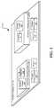
- FIG. 1is a block diagram of a wireless power delivery system
- FIG. 2is a more detailed block diagram of the wireless power delivery system
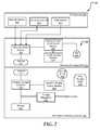
- FIG. 4shows a flow diagram of a method for controlling an amount of power provided from the wireless power delivery system
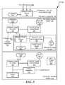
- FIG. 5shows a flow diagram of a method for controlling an amount of power received at an information handling system from the wireless power delivery system
- FIG. 6is a block diagram of a general information handling system.
- FIG. 1illustrates a wireless power delivery system 100 for an information handling system.
- the information handling systemmay include any instrumentality or aggregate of instrumentalities operable to compute, classify, process, transmit, receive, retrieve, originate, switch, store, display, manifest, detect, record, reproduce, handle, or utilize any form of information, intelligence, or data for business, scientific, control, entertainment, or other purposes.
- an information handling systemmay be a personal computer, a PDA, a consumer electronic device, a network server or storage device, a switch router or other network communication device, or any other suitable device and may vary in size, shape, performance, functionality, and price.
- the information handling systemmay include memory, one or more processing resources such as a central processing unit (CPU) or hardware or software control logic.
- CPUcentral processing unit
- Additional components of the information handling systemmay include one or more storage devices, one or more communications ports for communicating with external devices as well as various input and output (I/O) devices, such as a keyboard, a mouse, and a video display.
- the information handling systemmay also include one or more buses operable to transmit communications between the various hardware components.
- the wireless power delivery system 100includes a wireless charging pad 102 and information handling systems 104 and 106 .
- the wireless charging pad 102includes wireless power sources 108 and 110 , and antennas 112 and 114 .
- the information handling system 104includes an antenna 116 and a wireless charger 118 .
- the information handling system 106includes an antenna 120 and a wireless charger 122 .
- the wireless power source 108is in communication with the antenna 116 , which in turn is in communication with the antenna 116 of the information handling system 104 and with the antenna 120 of the information handling system 106 .
- the antenna 116is in communication with the wireless charger 118 .
- the antenna 120is in communication with the wireless charger 122 .
- the wireless charging pad 102can detect when a device such as one of the information handling systems 104 and 106 is placed on top of the wireless charging pad, and can transmit a detect signal in response to detecting the device.
- the wireless charging pad 102can detect the information handling system 104 when a light sensor on the wireless charging pad 102 is covered by the information handling system, by a pressure sensor of the wireless charging pad detecting the information handling system, by metal tabs of the wireless charging pad being placed in physical communication with the information handling system, and the like.
- the information handling system 104can receive the detect signal from the wireless charging pad, and can respond by transmitting a presence signal to the wireless charging pad.
- the presence signalcan include a repeating pulse signal, referred to as a chirp, and can also include information associated with the information handling system 104 , such as a class of the information handling system.
- the class of the information handling system 104can indicate a maximum power needed for the information handling system, or the like.
- the wireless charging pad 102can receive the presence signal from the information handling system 104 , and can then set an initial power level to be provided from the wireless power source 108 to the information handling system.
- the initial power levelcan be a minimum power level available from the wireless charging pad 102 , can be a maximum power level available from the wireless charging pad, or can be any power level in between the minimum and maximum power levels.
- the wireless charging pad 102can then transmit the wireless power to the information handling system 104 via the antenna 112 .
- the wireless charging pad 102can use one or more techniques to provide power wirelessly, including inductive techniques, resonant inductive techniques, capacitive transfer techniques, beamed power transfer, such as laser or microwave transfer, or the like.
- the wireless charging pad 102transfers power wirelessly using inductive power transfer.
- the antenna 116 of the information handling system 104can receive the wireless power from the antenna 112 and can provide the power to the wireless charger 118 , which in turn can convert the power to be used by the information handling system 104 .
- the information handling system 104can monitor its current operating conditions and can determine whether to change a power state of the information handling system. For example, if the information handling system 104 is receiving the maximum amount of power from the wireless charging pad 102 and then the information handling system enters a lower power mode, the information handling system can send a power state change signal to the wireless charging pad 102 .
- the power state changecan indicate a new power state for the information handling system 104 .
- the wireless charging pad 102can receive the power state change signal and can adjust the power level provided by the wireless power source 108 to the information handling system 104 , such that a proper power level is provided to the information handling system without having excess power that is not used or not having enough power for the information handling system.
- the information handling system 104can continually monitor its operating mode and can provide any necessary state change signals to the wireless charging pad 102 .
- the information handling system 106can also receive the detect signal from the wireless charging pad 102 in response to the information handling system being placed on top of the wireless charging pad.
- the information handling system 106can respond to the detect signal by transmitting a presence signal similar to the presence signal of the information handling system 104 to the wireless charging pad.
- the wireless charging pad 102can receive the presence signal from the information handling system 106 , and can then set an initial power level to be provided from the wireless power source 110 to the information handling system.
- the wireless powercan then be transmitted from the wireless charging pad 102 to the information handling system 106 via the antenna 114 .
- the antenna 120can receive the wireless power from the antenna 114 and can provide the power to the wireless charger 122 , which in turn can convert the power to be used by the information handling system 106 .
- the information handling system 106can monitor its operating modes and can provide any necessary state change signals to the wireless charging pad 102 in a substantially similar fashion as the information handling system 104 .
- the wireless charging pad 102when the wireless charging pad 102 provides wireless power to both of the information handling systems 104 and 106 , the wireless charging pad can provide equal amounts of power to each of the information handling systems, can prioritize which information handling system to provide more power to, or the like.
- the information handling systems 104 and 106can receive information indicating an amount of power to be provided to the information handling system from the wireless charging pad 102 , and the like.
- the information handling systems 104 and 106can utilize this information to determine whether the power available from the wireless charging pad 102 is enough to operate the information handling system at a maximum power operating mode or if the information handling system should operate in a lower operating mode.
- Each of the information handling systems 104 and 106can dynamically adjust its operating mode based on the power available from the wireless charging pad 102 .
- the wireless charging pad 102 and the information handling systems 104 and 106can continually provide feedback to each other to adjust the amount of power provided from the wireless charging pad to the information handling systems.
- FIG. 2shows a more detailed embodiment of the wireless power delivery system 100 including the wireless charging pad 102 , the information handling system 104 , and a plurality of direct current DC sources 206 in more detail.
- the wireless charging pad 102includes a landing pad 220 , which in turn includes a source-to-load limit control module 222 , a throttle control module 224 , an antenna 226 , the wireless power source 108 , and the antenna 112 .
- the antenna 112is in communication with the wireless power source 108 .
- the wireless power source 108is in communication with the source-to-load limit control module 222 , which in turn is in communication with the throttle control module 224 and with the antenna 226 .
- the wireless charging pad 102can include multiple landing pads that can each communicate with and provide wireless power to different information handling systems. However, for simplicity only one landing pad of the wireless charging pad 102 has been shown in FIG. 2 .
- the information handling system 104includes a battery 230 , voltage regulators 232 , a host/embedded controller (EC) throttle control module 234 , a near field communication (NFC) alternative Bluetooth Low Energy (BT LE) antenna 236 , and a NFC product Electronic Data Identification (EDID) tag 238 , the antenna 116 , and the wireless charger 118 .
- the antenna 116is in communication with the wireless charger 118 , which in turn is in communication with the battery 230 , with the voltage regulators 232 , and with the host/EC throttle control module 234 .
- the voltage regulators 232can provide multiple regulated voltages to different systems loads of the information handling system 104 , such as a central processing unit, a memory, a display device, and the like.
- the host/EC throttle control module 234is in communication with the NFC alternate BT LE antenna 236 .
- the host/EC throttle control module 234can be a hardware module, a software module, and/or any combination of a hardware and software module.
- the host/EC module 234can be a power management integrated circuit, a power management unit, or the like.
- the plurality of DC sources 206includes an automatic air source 240 , an alternating current (AC)-to-DC source 242 , and a universal serial bus (USB) power source 244 .
- Each of the automatic air source 240 , the AC-to-DC converter 242 , and the USB power source 244is in communication with the wireless power source 108 of the wireless charging pad 102 .
- the NFC product EDID tag 238can transmit a presence signal, referred to as a chirp, to indicate that the information handling system is within range of the wireless charging pad.
- the presence signalcan be a repeating pulse that can be received by the antenna 226 , which in turn can provide the presence signal to the source-to-load limit control 222 .
- the presence signal from the NFC product EDID 238can also include information about the information handling system 104 , such as a class of the information handling system.
- the source-to-load limit control module 222determines whether another signal is received from the throttle control module 224 . If a signal is not received from the throttle control module 224 , the source-to-load limit control module 222 can set an operation level of the wireless charging pad 102 to an initial operation level, such as a minimum level. The source-to-load limit control module 222 can send the operation level to the wireless power source 108 , which can receive power from one of the DC power sources 206 .
- the wireless power source 108can then provide power to the antenna 112 , which in turn can wirelessly provide the power to the antenna 116 of the information handling system 104 .
- the wireless charging pad 102can use one or more techniques to provide power wirelessly, including inductive techniques, resonant inductive techniques, capacitive transfer techniques, beamed power transfer, such as laser or microwave transfer, or the like.
- the antenna 116can receive the wireless power from the antenna 112 , and can provide power to the wireless charger 118 .
- the wireless charger 118can then convert the power received from the antenna 116 to a power source that can be utilized by the information handling system 104 .
- the wireless charger 118can either supply the converted power to the battery 230 or the voltage regulators 232 .
- the power provided to the battery 230can be used to charge the battery.
- the power provided to the voltage regulators 232can be supplied at proper voltage to the remaining components of the information handling system 104 .
- the host/EC throttle control module 234can receive information about the power provided by the wireless charging pad 102 from the wireless charger 118 .
- the informationcan include whether the wireless charging pad 102 is compatible with the wireless charger converter, a total amount of power that the wireless charging pad is able to provide, or the like.
- the host/EC throttle control module 234can also determine information about the information handling system 104 , such as a percentage of the battery 230 that is charged, an operation mode of the information handling system, and the like.
- the host/EC throttle control module 234determines that the wireless charging pad 102 is not compatible with the class of the information handling system 104 , the host/EC throttle control module can set a flag to cause the wireless charger 118 not to receive power from the wireless charging pad. The host/EC throttle control module 234 can also notify the user, via a display device, that the information handling system 104 is not receiving power from the wireless charging pad 102 . If the host/EC throttle control module 234 determines that the wireless charging pad 102 is compatible with the information handling system 104 , the host/EC throttle control module 234 can determine an amount of power that is available from the wireless charging pad.
- the host/EC throttle control module 234can modify an operating mode of the information handling system, such as operating below the maximum power. For example, the host/EC throttle control module 234 can cause the information handling system 104 to enter a standby or low power mode in response to determining that the maximum amount of power available from the wireless charging pad 102 is substantially less than the amount needed by the information handling system. The host/EC throttle control module 234 can cause the information handling system 104 to remain in the low power mode while the battery 230 is charged to a high enough capacity to operate the information handling system. In another embodiment, the host/EC throttle control module 234 can reduce the operational mode the information handling system 104 , such that the voltage supplied to the central processing unit, the memory, and other components of the information handling system is reduced.
- the host/EC throttle control module 234determines that the wireless charging pad 102 can provide more power than needed by the information handling system for maximum operation power, the host/EC throttle control module can determine a power state needed for the information handling system and can send the power state to the throttle control module 224 .
- the throttle control module 224receives the power state from the host/EC throttle control module 234 , the throttle control module can determine an operation level for the wireless charging pad 102 .
- the throttle control module 224can then send the operation level to the source-to-load limit control module 222 , which in turn can determine an amount of power to be provided by the wireless power source 108 .
- the source-to-load limit control module 222can send a signal to the wireless power source 108 to set the power level for the wireless power source to provide to the information handling system 104 via the antenna 112 .
- the wireless charger 118can receive power from the antenna 116 and can provide the power to either the battery 230 or the voltage regulators 232 . While the information handling system 104 is receiving power from the wireless charging pad 102 , the host/EC throttle control module 234 can continually monitor the operational mode of the information handling system 104 and can adjust the power state provided to the throttle control module 224 . For example, the information handling system 104 may operate in a maximum power mode, and may switch to a low power mode such that the information handling system does not need the same amount of power. The power state can indicate the amount of power to be provided to the information handling system 104 .
- the host/EC throttle control module 234can determine a new power state and send the new power state to the throttle control module 224 , which in turn can adjust the operation level of the wireless charging pad 102 .
- the change in the operation level of the wireless charging pad 102can result in a change in the amount of power provided to the information handling system 104 .
- the wireless charging pad 102can send information to the host/EC throttle control module 234 to indicate the current power available.
- the host/EC throttle control module 234can then set a flag to indicate that a certain amount of power cannot be received from the wireless charging pad 102 .
- the host/EC throttle control module 234can also set a flag when the battery 230 is fully charged.
- the host/EC throttle control module 234can then send information to the throttle control module 224 to indicate that the information handling system 104 does not currently need power from the wireless charging pad 102 .
- the host/EC throttle control module 234can clear any flags set. Thus, if the information handling system 104 begins to communicate with the wireless charging pad 102 again, the communication and setup between host/EC throttle control module 234 and the throttle control module 224 can restart as described above. In another embodiment, when the information handling system 104 is no longer in communication with the wireless charging pad 102 , the host/EC throttle control module 234 can continue to maintain the flag indicating that the battery 230 is fully charged until a point in time, if any, that the battery becomes less than fully charged.
- the throttle control module 224can detect that another information handling system, such as the information handling system 106 of FIG. 1 , has been placed in communication with a different landing pad of the wireless charging pad 102 .
- the throttle control modulecan determine that the other information handling system has a higher priority than the information handling system 104 , such that the wireless charging pad 102 provides the other information handling system with a certain amount of power before providing the information handling system 104 with power. In this situation, the throttle control module 224 may reduce the amount of power available to the information handling system 104 .
- the throttle control module 224can also send information indicating the reduced amount of power to the host/EC throttle control module 236 , so that the host/EC throttle control module can modify the operational mode of the information handling system 104 based on the reduced amount of power available. Therefore, the information handling system 104 and the wireless charging pad 102 can provide feedback to one another indicating the amount of power available, any power state changes, or the like to enable the wireless charging pad to dynamically provide a proper amount of power to the information handling system.
- FIG. 3shows another embodiment of the wireless power delivery system 100 including the wireless charging pad 102 , the information handling system 104 , and the information handling system 106 in more detail.
- the wireless charging pad 102includes the same components and operates in substantially the same manner as described in FIGS. 1 and 2 , but for simplicity only the wireless power source 108 and the antenna 112 have been shown.
- the antenna 112is in communication with the wireless power source 108 , which in turn is in communication with the source-to-load limit control module 222 .
- the information handling system 104includes a wireless charging pad 302 having a wireless power source 304 , an antenna 306 , a source-to-load limit control module 308 , a throttle control module 310 , and an antenna 312 .
- the information handling system 104also includes the same components but for simplicity only the antenna 116 , the wireless converter 118 , the host/EC throttle control module 234 , and the antenna 236 have been shown.
- the information handling system 106includes a battery 314 , voltage regulators 316 , a host/EC throttle control module 318 , a NFC alternative BT LE antenna 320 , and a NFC product EDID tag 322 , the antenna 120 , and the wireless charger 122 .
- the antenna 120is in communication with the wireless charger 122 , which in turn is in communication with the battery 314 , with the voltage regulators 316 , and with the host/EC throttle control module 318 .
- the voltage regulators 316can provide multiple regulated voltages to different systems loads of the information handling system 106 , such as a central processing unit, a memory, a display device, and the like.
- the host/EC throttle control module 318is in communication with the NFC alternate BT LE antenna 320 .
- the host/EC throttle control module 318can be a hardware module, a software module, and/or any combination of a hardware and software module.
- the host/EC module 318can be a power management integrated circuit, a power management unit, or the like.
- the NFC product EDID tag 322can transmit a presence signal, referred to as a chirp, to indicate that the information handling system 106 is within range of the wireless charging pad 302 of the information handling system 104 .
- the presence signalcan be a repeating pulse that can be received by the antenna 312 , which in turn can provide the presence signal to the source-to-load limit control 308 .
- the presence signal from the NFC product EDID 322can also include information about the information handling system 106 , such as a class of the information handling system.
- the wireless charging pad 302 of the information handling system 104can detect the information handling system 106 when a light sensor on the wireless charging pad 302 is covered by the information handling system 106 , by a pressure sensor of the wireless charging pad 302 detecting the information handling system 106 , by metal tabs of the wireless charging pad 302 being placed in physical communication with the information handling system 106 , and the like.
- the source-to-load limit control module 308determines whether another signal is received from the throttle control module 310 . If a signal is not received from the throttle control module 310 , the source-to-load limit control module 308 can set an operation level of the wireless charging pad 302 to an initial operation level, such as a minimum level. The source-to-load limit control module 308 can send the operation level to the wireless power source 304 , which can receive power from the wireless charger converter 118 , the battery 230 , and/or the voltage regulators 232 .
- the wireless power source 304can then provide power to the antenna 306 , which in turn can wirelessly provide the power to the antenna 120 of the information handling system 106 .
- the wireless charging pad 302can use one or more techniques to provide power wirelessly, including inductive techniques, resonant inductive techniques, capacitive transfer techniques, beamed power transfer, such as laser or microwave transfer, or the like.
- the antenna 120can receive the wireless power from the antenna 306 , and can provide power to the wireless charger 122 .
- the wireless charger 122can then convert the power received from the antenna 120 to a power source that can be utilized by the information handling system 106 .
- the wireless charger 122can either supply the converted power to the battery 314 or the voltage regulators 316 .
- the power provided to the battery 314can be used to charge the battery.
- the power provided to the voltage regulators 316can be supplied at proper voltage to the remaining components of the information handling system 106 .
- the host/EC throttle control module 318can receive information about the power provided by the wireless charging pad 302 from the wireless charger 122 .
- the informationcan include whether the wireless charging pad 302 is compatible with the wireless charger converter 122 , a total amount of power that the wireless charging pad is able to provide, or the like.
- the host/EC throttle control module 318can also determine information about the information handling system 106 , such as a percentage of the battery 314 that is charged, an operation mode of the information handling system, and the like.
- the host/EC throttle control module 318determines that the wireless charging pad 302 is not compatible with the class of the information handling system 106 , the host/EC throttle control module can set a flag to cause the wireless charger 122 not to receive power from the wireless charging pad. The host/EC throttle control module 318 can also notify the user, via a display device, that the information handling system 106 is not receiving power from the wireless charging pad 302 of the information handling system 104 . If the host/EC throttle control module 318 determines that the wireless charging pad 302 is compatible with the information handling system 106 , the host/EC throttle control module 318 can determine an amount of power that is available from the wireless charging pad.
- the host/EC throttle control module 318determines that the maximum amount of power available from the wireless charging pad 302 is less than the amount needed to operate the information handling system 106 at maximum power, the host/EC throttle control module can modify an operating mode of the information handling system, such as operating below the maximum power. For example, the host/EC throttle control module 318 can cause the information handling system 106 to enter a standby or low power mode in response to determining that the maximum amount of power available from the wireless charging pad 302 is substantially less than the amount needed by the information handling system. The host/EC throttle control module 318 can cause the information handling system 106 to remain in the low power mode until the battery 314 is charged to a high enough capacity to operate the information handling system. In another embodiment, the host/EC throttle control module 318 can reduce the operational mode the information handling system 106 , such that the voltage supplied to the central processing unit, the memory, and other components of the information handling system is reduced.
- the host/EC throttle control module 318determines that the wireless charging pad 302 can provide more power than needed by the information handling system 106 for maximum operation power
- the host/EC throttle control modulecan determine a power state needed for the information handling system and can send the power state to the throttle control module 310 .
- the throttle control module 310receives the power state from the host/EC throttle control module 318
- the throttle control modulecan determine an operation level for the wireless charging pad 302 .
- the throttle control module 310can then send the operation level to the source-to-load limit control module 308 , which in turn can determine an amount of power to be provided by the wireless charger converter 118 .
- the source-to-load limit control module 308can send a signal to the wireless power source 304 to set the power level for the wireless power source to provide to the information handling system 106 via the antenna 306 .
- the wireless charger 122can receive power from the antenna 120 and can provide the power to either the battery 314 or the voltage regulators 316 . While the information handling system 106 is receiving power from the wireless charging pad 302 , the host/EC throttle control module 318 can continually monitor the operational mode of the information handling system 106 and can adjust the power state provided to the throttle control module 310 . For example, the information handling system 106 may operate in a maximum power mode, and may switch to a low power mode such that the information handling system does not need the same amount of power. The power state can indicate the amount of power to be provided to the information handling system 106 .
- the host/EC throttle control module 318can determine a new power state and send the new power state to the throttle control module 310 , which in turn can adjust the operation level of the wireless charging pad 302 .
- the change in the operation level of the wireless charging pad 302can result in a change in the amount of power provided to the information handling system 106 .
- the wireless charging pad 302can send information to the host/EC throttle control module 318 to indicate the current power available.
- the host/EC throttle control module 318can then set a flag to indicate that a certain amount of power cannot be received from the wireless charging pad 302 .
- the host/EC throttle control module 318can also set a flag when the battery 314 is fully charged.
- the host/EC throttle control module 318can then send information to the throttle control module 310 to indicate that the information handling system 106 does not currently need power from the wireless charging pad 302 .
- the host/EC throttle control module 318can clear any flags set. Thus, if the information handling system 106 begins to communicate with the wireless charging pad 302 again, the communication and setup between host/EC throttle control module 318 and the throttle control module 310 can restart as described above. In another embodiment, when the information handling system 106 is no longer in communication with the wireless charging pad 302 , the host/EC throttle control module 318 can continue to maintain the flag indicating that the battery 314 is fully charged until a point in time, if any, that the battery becomes less than fully charged.
- the source-to-load limit control module 308 of wireless charging pad 302can communicate with the host/EC throttle control module 234 to provide information about the wireless charging pad to the host/EC throttle control module.
- the host/EC throttle control module 234can receive information indicating the amount of power being provided from the wireless charging pad 302 to the information handling system 106 , indicating an amount of power requested by the information handling system 106 , or the like.
- the host/EC throttle control module 234can utilize the amount of power requested by the wireless charging pad 302 to adjust an amount of power requested from the wireless charging pad 102 .
- a total amount of power received by the information handling system 104 from the wireless charging pad 102can include an amount of power to be provided to the battery 230 and the other components of the information handling system 104 , and an amount of power to be provided to the information handling system 106 via the wireless charging pad 302 . Therefore, the power state provided from the information handling system 104 to the wireless charging pad 102 can include a power state of the information handling system 106 combined with the power state of the information handling system 104 .
- FIG. 4shows a flow diagram of a method 400 for controlling an amount of power provided from a wireless power delivery system.
- a presence signalis received from an information handling system.
- the presence signalcan be received at a wireless charging pad via a near field communication (NFC) signal.
- NFCnear field communication
- the presence signalcan be a signal indicating that the information handling system is present, can be the signal combined with a class identifier for the information handling system, or the like.
- the class identifiercan indicate a maximum amount of power that the information handling system needs during operation.
- EDIDextended identification
- the EDIDcan include information about the power requirements for the information handling system, such as the maximum power the information handling system can receive, a nominal power for the information handling system, whether the information handling system is charging, in a low power mode, whether the an auxiliary battery needs to be charged, whether the information handling system is in standby mode, or the like.
- a state change, EDID information, and/or a second NFC signalare not received, power parameters of the wireless power delivery system are reset and the wireless power delivery system continues to poll the information handling system at block 406 , and the flow continues as stated above at block 404 .
- the wireless charging padcan provide a minimum power level when the power parameters are reset. If the state change, EDID information, and/or a second NFC are received, a determination is made whether an input base source or alternate power source is available at block 408 . If an input base source or an alternative power source is not available, then the flow continues as stated above at block 406 . If input base source or an alternative power source is available, then a power state needed for the information handling system is set at block 410 .
- the new power stateis used to drive a wireless power operation level of the wireless charging pad of the wireless power delivery system.
- a local wireless power time eventis set at block 414 , and then the flow returns to block 412 when the time event expires.
- the timer eventcan be a length of time to provide power the information handling system in the wireless power operation level.
- a determinationis made whether a power level of the wireless power delivery system needs to be increased based on the wireless power operation level. If the power level needs to be increased, the operation level is increased at block 418 , and a determination is made whether the power level is at a maximum at block 420 . In an embodiment, adjusting the operation level directly adjusts the power level provided by the wireless charging pad.
- the flowcontinues as state above at block 416 . If the operation level is at the maximum, the control of the wireless power delivery system is updated based on the power level maximum being reached at block 422 , and the flow continues as stated above at block 410 .
- the operation level of the wireless power delivery systemis decreased at block 424 .
- FIG. 5shows a flow diagram of a method 500 for controlling an amount of power to be received at an information handling system from a wireless power delivery system.
- a determinationis made whether wireless power is enabled in the information handling system. When wireless power is enabled a determination is made whether a valid wireless power source, such as a wireless charging pad, is available at block 504 . If a valid wireless power source is not available, then the flow continues as stated above at block 502 . If a valid wireless power source is available, a determination is made whether the information handling system is in bypass mode at block 506 . If the information handling system is in bypass mode, then a minimum power level for the information handling system is set based on the information handling system being in a bypass mode at block 508 .
- a valid wireless power sourcesuch as a wireless charging pad
- a power state of a needed power levelis set at block 512 .
- an alternate near field communication (NFC) antennais engaged and a power state is transmitted to the wireless charging pad.
- a local wireless power time eventis set at block 516 , and then the flow returns to block 514 when the time event expires.
- the timer eventcan be a length of time to provide power the information handling system in the wireless power operation level.
- an operating mode of the information handling systemis changed.
- a determinationis made whether a power state change is needed at block 520 . When a power state change is needed, a new power state is determined at block 522 , and the flow continues as stated above at block 512 .
- the presence signalcan be detected in a wireless charging pad of the information handling system, and the presence signal can be received from another information handling system.
- the information handling systemcan perform the flow described above at FIG. 4 to determine the power requirement for the new information handling system and to provide the new information handling system with power.
- the information handling systemcan then determine a new power state at block 522 and continue as described above at block 512 .
- the new power statecan be based on the power requirement of both the information handling system and the new information handling system that the information handling system provides power to.
- the information handling system 600can include a first physical processor 602 coupled to a first host bus 604 and can further include additional processors generally designated as n th physical processor 606 coupled to a second host bus 608 .
- the first physical processor 602can be coupled to a chipset 610 via the first host bus 604 .
- the n th physical processor 606can be coupled to the chipset 610 via the second host bus 608 .
- the chipset 610can support multiple processors and can allow for simultaneous processing of multiple processors and support the exchange of information within information handling system 600 during multiple processing operations.
- the chipset 610can be referred to as a memory hub or a memory controller.
- the chipset 610can include an Accelerated Hub Architecture (AHA) that uses a dedicated bus to transfer data between first physical processor 602 and the n th physical processor 606 .
- the chipset 610including an AHA enabled-chipset, can include a memory controller hub and an input/output (I/O) controller hub.
- the chipset 610can function to provide access to first physical processor 602 using first bus 604 and n th physical processor 606 using the second host bus 608 .
- the chipset 610can also provide a memory interface for accessing memory 612 using a memory bus 614 .
- the buses 604 , 608 , and 614can be individual buses or part of the same bus.
- the chipset 610can also provide bus control and can handle transfers between the buses 604 , 608 , and 614 .
- the chipset 610can be generally considered an application specific chipset that provides connectivity to various buses, and integrates other system functions.
- the chipset 610can be provided using an Intel® Hub Architecture (IHA) chipset that can also include two parts, a Graphics and AGP Memory Controller Hub (GMCH) and an I/O Controller Hub (ICH).
- IHAIntel® Hub Architecture
- GMCHGraphics and AGP Memory Controller Hub
- ICHI/O Controller Hub
- an Intel 820 E, an 815 E chipset, or any combination thereof, available from the Intel Corporation of Santa Clara, Calif.can provide at least a portion of the chipset 610 .
- the chipset 610can also be packaged as an application specific integrated circuit (ASIC).
- ASICapplication specific integrated circuit
- the information handling system 600can also include a video graphics interface 622 that can be coupled to the chipset 610 using a third host bus 624 .
- the video graphics interface 622can be an Accelerated Graphics Port (AGP) interface to display content within a video display unit 626 .
- AGPAccelerated Graphics Port
- Other graphics interfacesmay also be used.
- the video graphics interface 622can provide a video display output 628 to the video display unit 626 .
- the video display unit 626can include one or more types of video displays such as a flat panel display (FPD) or other type of display device.
- FPDflat panel display
- the information handling system 600can also include an I/O interface 630 that can be connected via an I/O bus 620 to the chipset 610 .
- the I/O interface 630 and I/O bus 620can include industry standard buses or proprietary buses and respective interfaces or controllers.
- the I/O bus 620can also include a Peripheral Component Interconnect (PCI) bus or a high speed PCI-Express bus.
- PCIPeripheral Component Interconnect
- a PCI buscan be operated at approximately 66 MHz and a PCI-Express bus can be operated at more than one speed, such as 2.5 GHz and 4 GHz.
- PCI buses and PCI-Express busescan be provided to comply with industry standards for connecting and communicating between various PCI-enabled hardware devices.
- I/O bus 620can also be provided in association with, or independent of, the I/O bus 620 including, but not limited to, industry standard buses or proprietary buses, such as Industry Standard Architecture (ISA), Small Computer Serial Interface (SCSI), Inter-Integrated Circuit (I 2 C), System Packet Interface (SPI), or Universal Serial buses (USBs).
- ISAIndustry Standard Architecture
- SCSISmall Computer Serial Interface
- I 2 CInter-Integrated Circuit
- SPISystem Packet Interface
- USBsUniversal Serial buses
- the chipset 610can be a chipset employing a Northbridge/Southbridge chipset configuration (not illustrated).
- a Northbridge portion of the chipset 610can communicate with the first physical processor 602 and can control interaction with the memory 612 , the I/O bus 620 that can be operable as a PCI bus, and activities for the video graphics interface 622 .
- the Northbridge portioncan also communicate with the first physical processor 602 using first bus 604 and the second bus 608 coupled to the n th physical processor 606 .
- the chipset 610can also include a Southbridge portion (not illustrated) of the chipset 610 and can handle I/O functions of the chipset 610 .
- the Southbridge portioncan manage the basic forms of I/O such as Universal Serial Bus (USB), serial I/O, audio outputs, Integrated Drive Electronics (IDE), and ISA I/O for the information handling system 600 .
- USBUniversal Serial Bus
- IDEIntegrated Drive Electronics
- ISA I/O
- the information handling system 600can further include a disk controller 632 coupled to the I/O bus 620 , and connecting one or more internal disk drives such as a hard disk drive (HDD) 634 and an optical disk drive (ODD) 636 such as a Read/Write Compact Disk (R/W CD), a Read/Write Digital Video Disk (R/W DVD), a Read/Write mini-Digital Video Disk (R/W mini-DVD), or other type of optical disk drive.
- HDDhard disk drive
- ODDoptical disk drive
- R/W CDRead/Write Compact Disk
- R/W DVDRead/Write Digital Video Disk
- R/W mini-DVDRead/Write mini-Digital Video Disk
- the methods described in the present disclosurecan be stored as instructions in a computer readable medium to cause a processor, such as chipset 610 , to perform the method.
- the methods described in the present disclosurecan be stored as instructions in a non-transitory computer readable medium, such as a hard disk drive, a solid state drive, a flash memory, and the like. Accordingly, all such modifications are intended to be included within the scope of the embodiments of the present disclosure as defined in the following claims.
- means-plus-function clausesare intended to cover the structures described herein as performing the recited function and not only structural equivalents, but also equivalent structures.
Landscapes
- Engineering & Computer Science (AREA)
- Power Engineering (AREA)
- Computer Networks & Wireless Communication (AREA)
- Theoretical Computer Science (AREA)
- Physics & Mathematics (AREA)
- General Engineering & Computer Science (AREA)
- General Physics & Mathematics (AREA)
- Signal Processing (AREA)
- Charge And Discharge Circuits For Batteries Or The Like (AREA)
Abstract
Description
Claims (14)
Priority Applications (2)
| Application Number | Priority Date | Filing Date | Title |
|---|---|---|---|
| US13/475,652US9218031B2 (en) | 2012-05-18 | 2012-05-18 | System and method for providing wireless power feedback in a wireless power delivery system |
| US14/942,662US10067546B2 (en) | 2012-05-18 | 2015-11-16 | System and method for providing wireless power feedback in a wireless power delivery system |
Applications Claiming Priority (1)
| Application Number | Priority Date | Filing Date | Title |
|---|---|---|---|
| US13/475,652US9218031B2 (en) | 2012-05-18 | 2012-05-18 | System and method for providing wireless power feedback in a wireless power delivery system |
Related Child Applications (1)
| Application Number | Title | Priority Date | Filing Date |
|---|---|---|---|
| US14/942,662ContinuationUS10067546B2 (en) | 2012-05-18 | 2015-11-16 | System and method for providing wireless power feedback in a wireless power delivery system |
Publications (2)
| Publication Number | Publication Date |
|---|---|
| US20130311798A1 US20130311798A1 (en) | 2013-11-21 |
| US9218031B2true US9218031B2 (en) | 2015-12-22 |
Family
ID=49582314
Family Applications (2)
| Application Number | Title | Priority Date | Filing Date |
|---|---|---|---|
| US13/475,652Active2033-09-15US9218031B2 (en) | 2012-05-18 | 2012-05-18 | System and method for providing wireless power feedback in a wireless power delivery system |
| US14/942,662Active2032-06-21US10067546B2 (en) | 2012-05-18 | 2015-11-16 | System and method for providing wireless power feedback in a wireless power delivery system |
Family Applications After (1)
| Application Number | Title | Priority Date | Filing Date |
|---|---|---|---|
| US14/942,662Active2032-06-21US10067546B2 (en) | 2012-05-18 | 2015-11-16 | System and method for providing wireless power feedback in a wireless power delivery system |
Country Status (1)
| Country | Link |
|---|---|
| US (2) | US9218031B2 (en) |
Cited By (4)
| Publication number | Priority date | Publication date | Assignee | Title |
|---|---|---|---|---|
| US20140159673A1 (en)* | 2012-12-07 | 2014-06-12 | Samsung Electronics Co., Ltd. | Wireless charging apparatus and method |
| US20160081041A1 (en)* | 2014-09-11 | 2016-03-17 | Xiaomi Inc. | Method and device for adjusting transmission power |
| US20180076649A1 (en)* | 2016-09-15 | 2018-03-15 | Hand E Holder Products, Inc. | Wireless charging apparatus |
| US11539219B2 (en) | 2017-04-07 | 2022-12-27 | Guangdong Oppo Mobile Telecommunications Corp., Ltd. | Wireless charging device and method, and device to be charged |
Families Citing this family (219)
| Publication number | Priority date | Publication date | Assignee | Title |
|---|---|---|---|---|
| US9166438B2 (en) | 2012-06-29 | 2015-10-20 | Dell Products, Lp | System and method for providing wireless power in a removable wireless charging module |
| US20150326070A1 (en) | 2014-05-07 | 2015-11-12 | Energous Corporation | Methods and Systems for Maximum Power Point Transfer in Receivers |
| US9871398B1 (en) | 2013-07-01 | 2018-01-16 | Energous Corporation | Hybrid charging method for wireless power transmission based on pocket-forming |
| US9876648B2 (en)* | 2014-08-21 | 2018-01-23 | Energous Corporation | System and method to control a wireless power transmission system by configuration of wireless power transmission control parameters |
| US10218227B2 (en) | 2014-05-07 | 2019-02-26 | Energous Corporation | Compact PIFA antenna |
| US10224982B1 (en) | 2013-07-11 | 2019-03-05 | Energous Corporation | Wireless power transmitters for transmitting wireless power and tracking whether wireless power receivers are within authorized locations |
| US9368020B1 (en) | 2013-05-10 | 2016-06-14 | Energous Corporation | Off-premises alert system and method for wireless power receivers in a wireless power network |
| US9900057B2 (en) | 2012-07-06 | 2018-02-20 | Energous Corporation | Systems and methods for assigning groups of antenas of a wireless power transmitter to different wireless power receivers, and determining effective phases to use for wirelessly transmitting power using the assigned groups of antennas |
| US9893555B1 (en) | 2013-10-10 | 2018-02-13 | Energous Corporation | Wireless charging of tools using a toolbox transmitter |
| US9853692B1 (en) | 2014-05-23 | 2017-12-26 | Energous Corporation | Systems and methods for wireless power transmission |
| US10050462B1 (en) | 2013-08-06 | 2018-08-14 | Energous Corporation | Social power sharing for mobile devices based on pocket-forming |
| US9787103B1 (en) | 2013-08-06 | 2017-10-10 | Energous Corporation | Systems and methods for wirelessly delivering power to electronic devices that are unable to communicate with a transmitter |
| US10090886B1 (en) | 2014-07-14 | 2018-10-02 | Energous Corporation | System and method for enabling automatic charging schedules in a wireless power network to one or more devices |
| US11502551B2 (en) | 2012-07-06 | 2022-11-15 | Energous Corporation | Wirelessly charging multiple wireless-power receivers using different subsets of an antenna array to focus energy at different locations |
| US10141791B2 (en) | 2014-05-07 | 2018-11-27 | Energous Corporation | Systems and methods for controlling communications during wireless transmission of power using application programming interfaces |
| US9867062B1 (en) | 2014-07-21 | 2018-01-09 | Energous Corporation | System and methods for using a remote server to authorize a receiving device that has requested wireless power and to determine whether another receiving device should request wireless power in a wireless power transmission system |
| US10199835B2 (en) | 2015-12-29 | 2019-02-05 | Energous Corporation | Radar motion detection using stepped frequency in wireless power transmission system |
| US9887584B1 (en) | 2014-08-21 | 2018-02-06 | Energous Corporation | Systems and methods for a configuration web service to provide configuration of a wireless power transmitter within a wireless power transmission system |
| US10063064B1 (en) | 2014-05-23 | 2018-08-28 | Energous Corporation | System and method for generating a power receiver identifier in a wireless power network |
| US10193396B1 (en) | 2014-05-07 | 2019-01-29 | Energous Corporation | Cluster management of transmitters in a wireless power transmission system |
| US10211674B1 (en) | 2013-06-12 | 2019-02-19 | Energous Corporation | Wireless charging using selected reflectors |
| US10008889B2 (en) | 2014-08-21 | 2018-06-26 | Energous Corporation | Method for automatically testing the operational status of a wireless power receiver in a wireless power transmission system |
| US9793758B2 (en) | 2014-05-23 | 2017-10-17 | Energous Corporation | Enhanced transmitter using frequency control for wireless power transmission |
| US10965164B2 (en) | 2012-07-06 | 2021-03-30 | Energous Corporation | Systems and methods of wirelessly delivering power to a receiver device |
| US9954374B1 (en) | 2014-05-23 | 2018-04-24 | Energous Corporation | System and method for self-system analysis for detecting a fault in a wireless power transmission Network |
| US9838083B2 (en) | 2014-07-21 | 2017-12-05 | Energous Corporation | Systems and methods for communication with remote management systems |
| US9893768B2 (en) | 2012-07-06 | 2018-02-13 | Energous Corporation | Methodology for multiple pocket-forming |
| US9882427B2 (en) | 2013-05-10 | 2018-01-30 | Energous Corporation | Wireless power delivery using a base station to control operations of a plurality of wireless power transmitters |
| US10211680B2 (en) | 2013-07-19 | 2019-02-19 | Energous Corporation | Method for 3 dimensional pocket-forming |
| US10291055B1 (en) | 2014-12-29 | 2019-05-14 | Energous Corporation | Systems and methods for controlling far-field wireless power transmission based on battery power levels of a receiving device |
| US10256657B2 (en) | 2015-12-24 | 2019-04-09 | Energous Corporation | Antenna having coaxial structure for near field wireless power charging |
| US9843213B2 (en) | 2013-08-06 | 2017-12-12 | Energous Corporation | Social power sharing for mobile devices based on pocket-forming |
| US9859797B1 (en) | 2014-05-07 | 2018-01-02 | Energous Corporation | Synchronous rectifier design for wireless power receiver |
| US10263432B1 (en) | 2013-06-25 | 2019-04-16 | Energous Corporation | Multi-mode transmitter with an antenna array for delivering wireless power and providing Wi-Fi access |
| US9973021B2 (en) | 2012-07-06 | 2018-05-15 | Energous Corporation | Receivers for wireless power transmission |
| US9991741B1 (en) | 2014-07-14 | 2018-06-05 | Energous Corporation | System for tracking and reporting status and usage information in a wireless power management system |
| US9143000B2 (en) | 2012-07-06 | 2015-09-22 | Energous Corporation | Portable wireless charging pad |
| US20140008993A1 (en) | 2012-07-06 | 2014-01-09 | DvineWave Inc. | Methodology for pocket-forming |
| US9876379B1 (en) | 2013-07-11 | 2018-01-23 | Energous Corporation | Wireless charging and powering of electronic devices in a vehicle |
| US9843201B1 (en) | 2012-07-06 | 2017-12-12 | Energous Corporation | Wireless power transmitter that selects antenna sets for transmitting wireless power to a receiver based on location of the receiver, and methods of use thereof |
| US9831718B2 (en) | 2013-07-25 | 2017-11-28 | Energous Corporation | TV with integrated wireless power transmitter |
| US10992187B2 (en) | 2012-07-06 | 2021-04-27 | Energous Corporation | System and methods of using electromagnetic waves to wirelessly deliver power to electronic devices |
| US10199849B1 (en) | 2014-08-21 | 2019-02-05 | Energous Corporation | Method for automatically testing the operational status of a wireless power receiver in a wireless power transmission system |
| US9912199B2 (en) | 2012-07-06 | 2018-03-06 | Energous Corporation | Receivers for wireless power transmission |
| US10128699B2 (en) | 2014-07-14 | 2018-11-13 | Energous Corporation | Systems and methods of providing wireless power using receiver device sensor inputs |
| US9824815B2 (en) | 2013-05-10 | 2017-11-21 | Energous Corporation | Wireless charging and powering of healthcare gadgets and sensors |
| US9923386B1 (en) | 2012-07-06 | 2018-03-20 | Energous Corporation | Systems and methods for wireless power transmission by modifying a number of antenna elements used to transmit power waves to a receiver |
| US10312715B2 (en) | 2015-09-16 | 2019-06-04 | Energous Corporation | Systems and methods for wireless power charging |
| US9899873B2 (en) | 2014-05-23 | 2018-02-20 | Energous Corporation | System and method for generating a power receiver identifier in a wireless power network |
| US9847679B2 (en) | 2014-05-07 | 2017-12-19 | Energous Corporation | System and method for controlling communication between wireless power transmitter managers |
| US9882430B1 (en) | 2014-05-07 | 2018-01-30 | Energous Corporation | Cluster management of transmitters in a wireless power transmission system |
| US10230266B1 (en) | 2014-02-06 | 2019-03-12 | Energous Corporation | Wireless power receivers that communicate status data indicating wireless power transmission effectiveness with a transmitter using a built-in communications component of a mobile device, and methods of use thereof |
| US10090699B1 (en) | 2013-11-01 | 2018-10-02 | Energous Corporation | Wireless powered house |
| US10224758B2 (en) | 2013-05-10 | 2019-03-05 | Energous Corporation | Wireless powering of electronic devices with selective delivery range |
| US9438045B1 (en) | 2013-05-10 | 2016-09-06 | Energous Corporation | Methods and systems for maximum power point transfer in receivers |
| US10223717B1 (en) | 2014-05-23 | 2019-03-05 | Energous Corporation | Systems and methods for payment-based authorization of wireless power transmission service |
| US9887739B2 (en) | 2012-07-06 | 2018-02-06 | Energous Corporation | Systems and methods for wireless power transmission by comparing voltage levels associated with power waves transmitted by antennas of a plurality of antennas of a transmitter to determine appropriate phase adjustments for the power waves |
| US10075008B1 (en) | 2014-07-14 | 2018-09-11 | Energous Corporation | Systems and methods for manually adjusting when receiving electronic devices are scheduled to receive wirelessly delivered power from a wireless power transmitter in a wireless power network |
| US10124754B1 (en) | 2013-07-19 | 2018-11-13 | Energous Corporation | Wireless charging and powering of electronic sensors in a vehicle |
| US9124125B2 (en) | 2013-05-10 | 2015-09-01 | Energous Corporation | Wireless power transmission with selective range |
| US10243414B1 (en) | 2014-05-07 | 2019-03-26 | Energous Corporation | Wearable device with wireless power and payload receiver |
| US10063105B2 (en) | 2013-07-11 | 2018-08-28 | Energous Corporation | Proximity transmitters for wireless power charging systems |
| US9941747B2 (en) | 2014-07-14 | 2018-04-10 | Energous Corporation | System and method for manually selecting and deselecting devices to charge in a wireless power network |
| US9948135B2 (en) | 2015-09-22 | 2018-04-17 | Energous Corporation | Systems and methods for identifying sensitive objects in a wireless charging transmission field |
| US9893554B2 (en) | 2014-07-14 | 2018-02-13 | Energous Corporation | System and method for providing health safety in a wireless power transmission system |
| US10211682B2 (en) | 2014-05-07 | 2019-02-19 | Energous Corporation | Systems and methods for controlling operation of a transmitter of a wireless power network based on user instructions received from an authenticated computing device powered or charged by a receiver of the wireless power network |
| US9941707B1 (en) | 2013-07-19 | 2018-04-10 | Energous Corporation | Home base station for multiple room coverage with multiple transmitters |
| US9906065B2 (en) | 2012-07-06 | 2018-02-27 | Energous Corporation | Systems and methods of transmitting power transmission waves based on signals received at first and second subsets of a transmitter's antenna array |
| US9941754B2 (en) | 2012-07-06 | 2018-04-10 | Energous Corporation | Wireless power transmission with selective range |
| US9939864B1 (en)* | 2014-08-21 | 2018-04-10 | Energous Corporation | System and method to control a wireless power transmission system by configuration of wireless power transmission control parameters |
| US10186913B2 (en) | 2012-07-06 | 2019-01-22 | Energous Corporation | System and methods for pocket-forming based on constructive and destructive interferences to power one or more wireless power receivers using a wireless power transmitter including a plurality of antennas |
| US9252628B2 (en) | 2013-05-10 | 2016-02-02 | Energous Corporation | Laptop computer as a transmitter for wireless charging |
| US10270261B2 (en) | 2015-09-16 | 2019-04-23 | Energous Corporation | Systems and methods of object detection in wireless power charging systems |
| US10063106B2 (en) | 2014-05-23 | 2018-08-28 | Energous Corporation | System and method for a self-system analysis in a wireless power transmission network |
| US10206185B2 (en) | 2013-05-10 | 2019-02-12 | Energous Corporation | System and methods for wireless power transmission to an electronic device in accordance with user-defined restrictions |
| US10439448B2 (en) | 2014-08-21 | 2019-10-08 | Energous Corporation | Systems and methods for automatically testing the communication between wireless power transmitter and wireless power receiver |
| US9859756B2 (en) | 2012-07-06 | 2018-01-02 | Energous Corporation | Transmittersand methods for adjusting wireless power transmission based on information from receivers |
| US10038337B1 (en) | 2013-09-16 | 2018-07-31 | Energous Corporation | Wireless power supply for rescue devices |
| US10141768B2 (en) | 2013-06-03 | 2018-11-27 | Energous Corporation | Systems and methods for maximizing wireless power transfer efficiency by instructing a user to change a receiver device's position |
| US9966765B1 (en) | 2013-06-25 | 2018-05-08 | Energous Corporation | Multi-mode transmitter |
| US9847677B1 (en) | 2013-10-10 | 2017-12-19 | Energous Corporation | Wireless charging and powering of healthcare gadgets and sensors |
| US9876394B1 (en) | 2014-05-07 | 2018-01-23 | Energous Corporation | Boost-charger-boost system for enhanced power delivery |
| US10103582B2 (en) | 2012-07-06 | 2018-10-16 | Energous Corporation | Transmitters for wireless power transmission |
| US9899861B1 (en) | 2013-10-10 | 2018-02-20 | Energous Corporation | Wireless charging methods and systems for game controllers, based on pocket-forming |
| US10291066B1 (en) | 2014-05-07 | 2019-05-14 | Energous Corporation | Power transmission control systems and methods |
| US12057715B2 (en) | 2012-07-06 | 2024-08-06 | Energous Corporation | Systems and methods of wirelessly delivering power to a wireless-power receiver device in response to a change of orientation of the wireless-power receiver device |
| US9853458B1 (en) | 2014-05-07 | 2017-12-26 | Energous Corporation | Systems and methods for device and power receiver pairing |
| US9812890B1 (en) | 2013-07-11 | 2017-11-07 | Energous Corporation | Portable wireless charging pad |
| US10205239B1 (en) | 2014-05-07 | 2019-02-12 | Energous Corporation | Compact PIFA antenna |
| US9806564B2 (en) | 2014-05-07 | 2017-10-31 | Energous Corporation | Integrated rectifier and boost converter for wireless power transmission |
| US10148097B1 (en) | 2013-11-08 | 2018-12-04 | Energous Corporation | Systems and methods for using a predetermined number of communication channels of a wireless power transmitter to communicate with different wireless power receivers |
| US10128693B2 (en) | 2014-07-14 | 2018-11-13 | Energous Corporation | System and method for providing health safety in a wireless power transmission system |
| US9859757B1 (en) | 2013-07-25 | 2018-01-02 | Energous Corporation | Antenna tile arrangements in electronic device enclosures |
| US9825674B1 (en) | 2014-05-23 | 2017-11-21 | Energous Corporation | Enhanced transmitter that selects configurations of antenna elements for performing wireless power transmission and receiving functions |
| US10381880B2 (en) | 2014-07-21 | 2019-08-13 | Energous Corporation | Integrated antenna structure arrays for wireless power transmission |
| US10992185B2 (en) | 2012-07-06 | 2021-04-27 | Energous Corporation | Systems and methods of using electromagnetic waves to wirelessly deliver power to game controllers |
| US9891669B2 (en) | 2014-08-21 | 2018-02-13 | Energous Corporation | Systems and methods for a configuration web service to provide configuration of a wireless power transmitter within a wireless power transmission system |
| US9356457B2 (en)* | 2012-12-20 | 2016-05-31 | Nxp B.V. | Wireless charging using passive NFC tag and multiple antenna of differing shapes |
| US8972296B2 (en) | 2012-12-31 | 2015-03-03 | Ebay Inc. | Dongle facilitated wireless consumer payments |
| US9819230B2 (en) | 2014-05-07 | 2017-11-14 | Energous Corporation | Enhanced receiver for wireless power transmission |
| US9419443B2 (en) | 2013-05-10 | 2016-08-16 | Energous Corporation | Transducer sound arrangement for pocket-forming |
| US9866279B2 (en) | 2013-05-10 | 2018-01-09 | Energous Corporation | Systems and methods for selecting which power transmitter should deliver wireless power to a receiving device in a wireless power delivery network |
| US9537357B2 (en) | 2013-05-10 | 2017-01-03 | Energous Corporation | Wireless sound charging methods and systems for game controllers, based on pocket-forming |
| US9538382B2 (en) | 2013-05-10 | 2017-01-03 | Energous Corporation | System and method for smart registration of wireless power receivers in a wireless power network |
| US10103552B1 (en) | 2013-06-03 | 2018-10-16 | Energous Corporation | Protocols for authenticated wireless power transmission |
| US10003211B1 (en) | 2013-06-17 | 2018-06-19 | Energous Corporation | Battery life of portable electronic devices |
| US10021523B2 (en) | 2013-07-11 | 2018-07-10 | Energous Corporation | Proximity transmitters for wireless power charging systems |
| US9979440B1 (en) | 2013-07-25 | 2018-05-22 | Energous Corporation | Antenna tile arrangements configured to operate as one functional unit |
| US9935482B1 (en) | 2014-02-06 | 2018-04-03 | Energous Corporation | Wireless power transmitters that transmit at determined times based on power availability and consumption at a receiving mobile device |
| US10075017B2 (en) | 2014-02-06 | 2018-09-11 | Energous Corporation | External or internal wireless power receiver with spaced-apart antenna elements for charging or powering mobile devices using wirelessly delivered power |
| CN104980969B (en)* | 2014-04-01 | 2019-03-26 | 华为技术有限公司 | Device, method and the terminal that wireless signal is handled |
| US9966784B2 (en) | 2014-06-03 | 2018-05-08 | Energous Corporation | Systems and methods for extending battery life of portable electronic devices charged by sound |
| US10158257B2 (en) | 2014-05-01 | 2018-12-18 | Energous Corporation | System and methods for using sound waves to wirelessly deliver power to electronic devices |
| US10153653B1 (en) | 2014-05-07 | 2018-12-11 | Energous Corporation | Systems and methods for using application programming interfaces to control communications between a transmitter and a receiver |
| US9800172B1 (en) | 2014-05-07 | 2017-10-24 | Energous Corporation | Integrated rectifier and boost converter for boosting voltage received from wireless power transmission waves |
| US10153645B1 (en) | 2014-05-07 | 2018-12-11 | Energous Corporation | Systems and methods for designating a master power transmitter in a cluster of wireless power transmitters |
| US10170917B1 (en) | 2014-05-07 | 2019-01-01 | Energous Corporation | Systems and methods for managing and controlling a wireless power network by establishing time intervals during which receivers communicate with a transmitter |
| US9973008B1 (en) | 2014-05-07 | 2018-05-15 | Energous Corporation | Wireless power receiver with boost converters directly coupled to a storage element |
| US9876536B1 (en) | 2014-05-23 | 2018-01-23 | Energous Corporation | Systems and methods for assigning groups of antennas to transmit wireless power to different wireless power receivers |
| US9881303B2 (en) | 2014-06-05 | 2018-01-30 | Paypal, Inc. | Systems and methods for implementing automatic payer authentication |
| US9871301B2 (en) | 2014-07-21 | 2018-01-16 | Energous Corporation | Integrated miniature PIFA with artificial magnetic conductor metamaterials |
| US10116143B1 (en) | 2014-07-21 | 2018-10-30 | Energous Corporation | Integrated antenna arrays for wireless power transmission |
| US10068703B1 (en) | 2014-07-21 | 2018-09-04 | Energous Corporation | Integrated miniature PIFA with artificial magnetic conductor metamaterials |
| US9917477B1 (en) | 2014-08-21 | 2018-03-13 | Energous Corporation | Systems and methods for automatically testing the communication between power transmitter and wireless receiver |
| US9965009B1 (en) | 2014-08-21 | 2018-05-08 | Energous Corporation | Systems and methods for assigning a power receiver to individual power transmitters based on location of the power receiver |
| JP2016059162A (en)* | 2014-09-09 | 2016-04-21 | シャープ株式会社 | Information communication device |
| US10122415B2 (en) | 2014-12-27 | 2018-11-06 | Energous Corporation | Systems and methods for assigning a set of antennas of a wireless power transmitter to a wireless power receiver based on a location of the wireless power receiver |
| US9893535B2 (en) | 2015-02-13 | 2018-02-13 | Energous Corporation | Systems and methods for determining optimal charging positions to maximize efficiency of power received from wirelessly delivered sound wave energy |
| US10110042B2 (en) | 2015-09-01 | 2018-10-23 | Dell Products, Lp | Cart for wirelessly recharging mobile computing devices |
| US9859728B2 (en) | 2015-09-01 | 2018-01-02 | Dell Products, Lp | System for securing a wireless power pad |
| US10148115B2 (en) | 2015-09-01 | 2018-12-04 | Dell Products, Lp | Wireless charging pad with natural draft cooling and method therefor |
| US9954388B2 (en) | 2015-09-01 | 2018-04-24 | Dell Products, Lp | Cover system for wireless power pad |
| US9905359B2 (en) | 2015-09-01 | 2018-02-27 | Dell Products, Lp | Wireless power antenna winding including heat pipe and method therefor |
| US9973027B2 (en) | 2015-09-01 | 2018-05-15 | Dell Products, Lp | Wireless power charging device with rear side magneto isolation marking |
| US9954387B2 (en) | 2015-09-01 | 2018-04-24 | Dell Products, Lp | Wireless charging pad with interdependent temperature control and method therefor |
| US9887555B2 (en) | 2015-09-01 | 2018-02-06 | Dell Products, Lp | Articulating receiver for wireless power delivery system |
| US9876382B2 (en) | 2015-09-01 | 2018-01-23 | Dell Products, Lp | Peak power caching in a wireless power system |
| US9912187B2 (en) | 2015-09-01 | 2018-03-06 | Dell Products, Lp | Wireless power transmission antenna with thermally conductive magnetic shield and method therefor |
| US10523033B2 (en) | 2015-09-15 | 2019-12-31 | Energous Corporation | Receiver devices configured to determine location within a transmission field |
| US12283828B2 (en) | 2015-09-15 | 2025-04-22 | Energous Corporation | Receiver devices configured to determine location within a transmission field |
| US9906275B2 (en) | 2015-09-15 | 2018-02-27 | Energous Corporation | Identifying receivers in a wireless charging transmission field |
| US10008875B1 (en) | 2015-09-16 | 2018-06-26 | Energous Corporation | Wireless power transmitter configured to transmit power waves to a predicted location of a moving wireless power receiver |
| US10778041B2 (en) | 2015-09-16 | 2020-09-15 | Energous Corporation | Systems and methods for generating power waves in a wireless power transmission system |
| US10211685B2 (en) | 2015-09-16 | 2019-02-19 | Energous Corporation | Systems and methods for real or near real time wireless communications between a wireless power transmitter and a wireless power receiver |
| US11710321B2 (en) | 2015-09-16 | 2023-07-25 | Energous Corporation | Systems and methods of object detection in wireless power charging systems |
| US9941752B2 (en) | 2015-09-16 | 2018-04-10 | Energous Corporation | Systems and methods of object detection in wireless power charging systems |
| US9893538B1 (en) | 2015-09-16 | 2018-02-13 | Energous Corporation | Systems and methods of object detection in wireless power charging systems |
| US9871387B1 (en) | 2015-09-16 | 2018-01-16 | Energous Corporation | Systems and methods of object detection using one or more video cameras in wireless power charging systems |
| US10186893B2 (en) | 2015-09-16 | 2019-01-22 | Energous Corporation | Systems and methods for real time or near real time wireless communications between a wireless power transmitter and a wireless power receiver |
| US10199850B2 (en) | 2015-09-16 | 2019-02-05 | Energous Corporation | Systems and methods for wirelessly transmitting power from a transmitter to a receiver by determining refined locations of the receiver in a segmented transmission field associated with the transmitter |
| US10158259B1 (en) | 2015-09-16 | 2018-12-18 | Energous Corporation | Systems and methods for identifying receivers in a transmission field by transmitting exploratory power waves towards different segments of a transmission field |
| US10027168B2 (en) | 2015-09-22 | 2018-07-17 | Energous Corporation | Systems and methods for generating and transmitting wireless power transmission waves using antennas having a spacing that is selected by the transmitter |
| US10050470B1 (en) | 2015-09-22 | 2018-08-14 | Energous Corporation | Wireless power transmission device having antennas oriented in three dimensions |
| US10128686B1 (en) | 2015-09-22 | 2018-11-13 | Energous Corporation | Systems and methods for identifying receiver locations using sensor technologies |
| US10020678B1 (en) | 2015-09-22 | 2018-07-10 | Energous Corporation | Systems and methods for selecting antennas to generate and transmit power transmission waves |
| US10153660B1 (en) | 2015-09-22 | 2018-12-11 | Energous Corporation | Systems and methods for preconfiguring sensor data for wireless charging systems |
| US10135294B1 (en) | 2015-09-22 | 2018-11-20 | Energous Corporation | Systems and methods for preconfiguring transmission devices for power wave transmissions based on location data of one or more receivers |
| US10033222B1 (en) | 2015-09-22 | 2018-07-24 | Energous Corporation | Systems and methods for determining and generating a waveform for wireless power transmission waves |
| US10135295B2 (en) | 2015-09-22 | 2018-11-20 | Energous Corporation | Systems and methods for nullifying energy levels for wireless power transmission waves |
| US9952647B2 (en)* | 2015-09-23 | 2018-04-24 | International Business Machines Corporation | Managed collaborative charging |
| US10734717B2 (en) | 2015-10-13 | 2020-08-04 | Energous Corporation | 3D ceramic mold antenna |
| US10333332B1 (en) | 2015-10-13 | 2019-06-25 | Energous Corporation | Cross-polarized dipole antenna |
| US9899744B1 (en) | 2015-10-28 | 2018-02-20 | Energous Corporation | Antenna for wireless charging systems |
| US9853485B2 (en) | 2015-10-28 | 2017-12-26 | Energous Corporation | Antenna for wireless charging systems |
| US10063108B1 (en) | 2015-11-02 | 2018-08-28 | Energous Corporation | Stamped three-dimensional antenna |
| US10135112B1 (en) | 2015-11-02 | 2018-11-20 | Energous Corporation | 3D antenna mount |
| US10027180B1 (en) | 2015-11-02 | 2018-07-17 | Energous Corporation | 3D triple linear antenna that acts as heat sink |
| US10545907B2 (en) | 2015-12-24 | 2020-01-28 | Intel Corporation | Adjustable power delivery scheme for universal serial bus |
| US10320446B2 (en) | 2015-12-24 | 2019-06-11 | Energous Corporation | Miniaturized highly-efficient designs for near-field power transfer system |
| US10116162B2 (en) | 2015-12-24 | 2018-10-30 | Energous Corporation | Near field transmitters with harmonic filters for wireless power charging |
| US10038332B1 (en) | 2015-12-24 | 2018-07-31 | Energous Corporation | Systems and methods of wireless power charging through multiple receiving devices |
| US20170187219A1 (en)* | 2015-12-24 | 2017-06-29 | Intel Corporation | Wireless charging system |
| US11863001B2 (en) | 2015-12-24 | 2024-01-02 | Energous Corporation | Near-field antenna for wireless power transmission with antenna elements that follow meandering patterns |
| US10027159B2 (en) | 2015-12-24 | 2018-07-17 | Energous Corporation | Antenna for transmitting wireless power signals |
| US10256677B2 (en) | 2016-12-12 | 2019-04-09 | Energous Corporation | Near-field RF charging pad with adaptive loading to efficiently charge an electronic device at any position on the pad |
| US10079515B2 (en) | 2016-12-12 | 2018-09-18 | Energous Corporation | Near-field RF charging pad with multi-band antenna element with adaptive loading to efficiently charge an electronic device at any position on the pad |
| US10008886B2 (en) | 2015-12-29 | 2018-06-26 | Energous Corporation | Modular antennas with heat sinks in wireless power transmission systems |
| US9658670B1 (en) | 2016-01-13 | 2017-05-23 | Dell Products, L.P. | Free device placement for wireless charging |
| US10923954B2 (en) | 2016-11-03 | 2021-02-16 | Energous Corporation | Wireless power receiver with a synchronous rectifier |
| US10401932B2 (en)* | 2016-12-01 | 2019-09-03 | Dell Products L.P. | Display base wireless charging pad and integrated charger control |
| KR102185600B1 (en) | 2016-12-12 | 2020-12-03 | 에너저스 코포레이션 | A method of selectively activating antenna zones of a near field charging pad to maximize transmitted wireless power |
| US10680319B2 (en) | 2017-01-06 | 2020-06-09 | Energous Corporation | Devices and methods for reducing mutual coupling effects in wireless power transmission systems |
| US10389161B2 (en) | 2017-03-15 | 2019-08-20 | Energous Corporation | Surface mount dielectric antennas for wireless power transmitters |
| US10439442B2 (en) | 2017-01-24 | 2019-10-08 | Energous Corporation | Microstrip antennas for wireless power transmitters |
| US10361590B2 (en) | 2017-03-13 | 2019-07-23 | Dell Products, Lp | Wireless power system with device specific power configuration and method therefor |
| US10523037B2 (en) | 2017-03-13 | 2019-12-31 | Dell Products, Lp | Thermal management at a wireless power system |
| US10476307B2 (en) | 2017-03-13 | 2019-11-12 | Dell Products, Lp | Wireless power system with foreign object detection and method therefor |
| US11011942B2 (en) | 2017-03-30 | 2021-05-18 | Energous Corporation | Flat antennas having two or more resonant frequencies for use in wireless power transmission systems |
| US10511097B2 (en) | 2017-05-12 | 2019-12-17 | Energous Corporation | Near-field antennas for accumulating energy at a near-field distance with minimal far-field gain |
| US12074460B2 (en) | 2017-05-16 | 2024-08-27 | Wireless Electrical Grid Lan, Wigl Inc. | Rechargeable wireless power bank and method of using |
| US11462949B2 (en) | 2017-05-16 | 2022-10-04 | Wireless electrical Grid LAN, WiGL Inc | Wireless charging method and system |
| US12074452B2 (en) | 2017-05-16 | 2024-08-27 | Wireless Electrical Grid Lan, Wigl Inc. | Networked wireless charging system |
| US10848853B2 (en) | 2017-06-23 | 2020-11-24 | Energous Corporation | Systems, methods, and devices for utilizing a wire of a sound-producing device as an antenna for receipt of wirelessly delivered power |
| US10811895B2 (en)* | 2017-07-25 | 2020-10-20 | Dell Products, L.P. | Wireless charging with power flux boost in an information handling system |
| US10122219B1 (en) | 2017-10-10 | 2018-11-06 | Energous Corporation | Systems, methods, and devices for using a battery as a antenna for receiving wirelessly delivered power from radio frequency power waves |
| US11342798B2 (en) | 2017-10-30 | 2022-05-24 | Energous Corporation | Systems and methods for managing coexistence of wireless-power signals and data signals operating in a same frequency band |
| US10615647B2 (en) | 2018-02-02 | 2020-04-07 | Energous Corporation | Systems and methods for detecting wireless power receivers and other objects at a near-field charging pad |
| US11159057B2 (en) | 2018-03-14 | 2021-10-26 | Energous Corporation | Loop antennas with selectively-activated feeds to control propagation patterns of wireless power signals |
| US11515732B2 (en) | 2018-06-25 | 2022-11-29 | Energous Corporation | Power wave transmission techniques to focus wirelessly delivered power at a receiving device |
| US11437735B2 (en) | 2018-11-14 | 2022-09-06 | Energous Corporation | Systems for receiving electromagnetic energy using antennas that are minimally affected by the presence of the human body |
| US11316385B2 (en)* | 2018-11-27 | 2022-04-26 | International Business Machines Corporation | Wireless energy transfer |
| US11539243B2 (en) | 2019-01-28 | 2022-12-27 | Energous Corporation | Systems and methods for miniaturized antenna for wireless power transmissions |
| EP3921945A1 (en) | 2019-02-06 | 2021-12-15 | Energous Corporation | Systems and methods of estimating optimal phases to use for individual antennas in an antenna array |
| CN109787315A (en) | 2019-02-19 | 2019-05-21 | 同方威视技术股份有限公司 | Wireless charging device and safety device including wireless charging device |
| US12155231B2 (en) | 2019-04-09 | 2024-11-26 | Energous Corporation | Asymmetric spiral antennas for wireless power transmission and reception |
| WO2021055901A1 (en) | 2019-09-20 | 2021-03-25 | Energous Corporation | Asymmetric spiral antennas with parasitic elements for wireless power transmission |
| US11381118B2 (en) | 2019-09-20 | 2022-07-05 | Energous Corporation | Systems and methods for machine learning based foreign object detection for wireless power transmission |
| WO2021055898A1 (en) | 2019-09-20 | 2021-03-25 | Energous Corporation | Systems and methods for machine learning based foreign object detection for wireless power transmission |
| CN114731061A (en) | 2019-09-20 | 2022-07-08 | 艾诺格思公司 | Classifying and detecting foreign objects using a power amplifier controller integrated circuit in a wireless power transmission system |
| WO2021055899A1 (en) | 2019-09-20 | 2021-03-25 | Energous Corporation | Systems and methods of protecting wireless power receivers using multiple rectifiers and establishing in-band communications using multiple rectifiers |
| WO2021079822A1 (en)* | 2019-10-24 | 2021-04-29 | 京セラ株式会社 | Power receiving device for optical power feed system, power feed device, and optical power feed system |
| US11355966B2 (en) | 2019-12-13 | 2022-06-07 | Energous Corporation | Charging pad with guiding contours to align an electronic device on the charging pad and efficiently transfer near-field radio-frequency energy to the electronic device |
| US10985617B1 (en) | 2019-12-31 | 2021-04-20 | Energous Corporation | System for wirelessly transmitting energy at a near-field distance without using beam-forming control |
| US11237632B2 (en) | 2020-03-03 | 2022-02-01 | Finch Technologies Ltd. | Ring device having an antenna, a touch pad, and/or a charging pad to control a computing device based on user motions |
| US11799324B2 (en) | 2020-04-13 | 2023-10-24 | Energous Corporation | Wireless-power transmitting device for creating a uniform near-field charging area |
| US11469629B2 (en) | 2020-08-12 | 2022-10-11 | Energous Corporation | Systems and methods for secure wireless transmission of power using unidirectional communication signals from a wireless-power-receiving device |
| US12306285B2 (en) | 2020-12-01 | 2025-05-20 | Energous Corporation | Systems and methods for using one or more sensors to detect and classify objects in a keep-out zone of a wireless-power transmission field, and antennas with integrated sensor arrangements |
| US11916398B2 (en) | 2021-12-29 | 2024-02-27 | Energous Corporation | Small form-factor devices with integrated and modular harvesting receivers, and shelving-mounted wireless-power transmitters for use therewith |
| US12142939B2 (en) | 2022-05-13 | 2024-11-12 | Energous Corporation | Integrated wireless-power-transmission platform designed to operate in multiple bands, and multi-band antennas for use therewith |
Citations (15)
| Publication number | Priority date | Publication date | Assignee | Title |
|---|---|---|---|---|
| US20100083012A1 (en)* | 2008-09-26 | 2010-04-01 | Mark Corbridge | Inductive Signal Transfer System for Computing Devices |
| US20100146308A1 (en)* | 2008-09-26 | 2010-06-10 | Richard Gioscia | Portable power supply device for mobile computing devices |
| US20100171461A1 (en)* | 2009-01-06 | 2010-07-08 | Access Business Group International Llc | Wireless charging system with device power compliance |
| US20100253281A1 (en)* | 2009-04-07 | 2010-10-07 | Qualcomm Incorporated | Wireless power transmission scheduling |
| US20110115430A1 (en)* | 2009-11-18 | 2011-05-19 | Nokia Corporation | Wireless energy repeater |
| US20110136550A1 (en)* | 2008-08-18 | 2011-06-09 | Nxp B.V. | Mobile device to control a charge pad system |
| US20110179292A1 (en) | 2010-01-21 | 2011-07-21 | Dell Products L.P. | Soft start with active reset |
| US20110202777A1 (en) | 2010-02-17 | 2011-08-18 | Dell Products, Lp | Power Module for Information Handling System and Methods Thereof |
| US20120214418A1 (en)* | 2011-02-23 | 2012-08-23 | Jungseok Lee | Wireless charging of mobile device |
| US20120313446A1 (en)* | 2011-06-07 | 2012-12-13 | Samsung Electronics Co., Ltd. | Method and apparatus for controlling wireless power of a receiver in a wireless power transmission/reception system |
| US20130007473A1 (en)* | 2011-06-30 | 2013-01-03 | Broadcom Corporation | Adaptive Power Management |
| US8412963B2 (en)* | 2010-04-26 | 2013-04-02 | Fu Da Tong Technology Co., Ltd. | Power supplying and data transmitting method for induction type power supply system |
| US20130154557A1 (en)* | 2011-12-15 | 2013-06-20 | Samsung Electronics Co., Ltd. | Apparatus and method for transmitting wireless power |
| US20130207599A1 (en)* | 2012-02-10 | 2013-08-15 | Sandisk Technologies Inc. | Regulation of wirelessly charging multiple devices from the same source |
| US20130234661A1 (en)* | 2010-12-17 | 2013-09-12 | Lg Electronics Inc. | Method for transmitting power wirelessly, method for receiving power wirelessly, wireless power transmitting device, and wireless power receiving device |
Family Cites Families (12)
| Publication number | Priority date | Publication date | Assignee | Title |
|---|---|---|---|---|
| GB2414121B (en)* | 2004-05-11 | 2008-04-02 | Splashpower Ltd | Controlling inductive power transfer systems |
| US8193764B2 (en)* | 2007-08-08 | 2012-06-05 | Jay Marketing Associates, Inc. | Wireless charging of electronic devices |
| US8175660B2 (en)* | 2007-10-30 | 2012-05-08 | Qualcomm Incorporated | Wireless energy transfer |
| WO2009069844A1 (en)* | 2007-11-30 | 2009-06-04 | Chun-Kil Jung | Multiple non-contact charging system of wireless power transmision and control method thereof |
| US8427100B2 (en)* | 2009-02-06 | 2013-04-23 | Broadcom Corporation | Increasing efficiency of wireless power transfer |
| EP2546956B1 (en)* | 2010-03-12 | 2021-01-20 | Samsung Electronics Co., Ltd | Method for wireless charging of a mobile terminal and mobile terminal for same |
| TWM389866U (en)* | 2010-03-30 | 2010-10-01 | Winharbor Technology Co Ltd | Notebook with wireless charging |
| KR101743777B1 (en)* | 2010-10-21 | 2017-06-05 | 삼성전자주식회사 | Method for wireless charging and apparatus for the same |
| US9244500B2 (en)* | 2011-05-23 | 2016-01-26 | Intel Corporation | System integration supporting completely wireless peripheral applications |
| US20130026981A1 (en)* | 2011-07-28 | 2013-01-31 | Broadcom Corporation | Dual mode wireless power |
| US9419444B2 (en)* | 2011-10-05 | 2016-08-16 | Blackberry Limited | Wireless charging and communication with power source devices and power charge devices in a communication system |
| KR101890625B1 (en)* | 2012-04-24 | 2018-08-22 | 엘지전자 주식회사 | Mobile terminal providing wireless charging and method for controlling the same |
- 2012
- 2012-05-18USUS13/475,652patent/US9218031B2/enactiveActive
- 2015
- 2015-11-16USUS14/942,662patent/US10067546B2/enactiveActive
Patent Citations (15)
| Publication number | Priority date | Publication date | Assignee | Title |
|---|---|---|---|---|
| US20110136550A1 (en)* | 2008-08-18 | 2011-06-09 | Nxp B.V. | Mobile device to control a charge pad system |
| US20100083012A1 (en)* | 2008-09-26 | 2010-04-01 | Mark Corbridge | Inductive Signal Transfer System for Computing Devices |
| US20100146308A1 (en)* | 2008-09-26 | 2010-06-10 | Richard Gioscia | Portable power supply device for mobile computing devices |
| US20100171461A1 (en)* | 2009-01-06 | 2010-07-08 | Access Business Group International Llc | Wireless charging system with device power compliance |
| US20100253281A1 (en)* | 2009-04-07 | 2010-10-07 | Qualcomm Incorporated | Wireless power transmission scheduling |
| US20110115430A1 (en)* | 2009-11-18 | 2011-05-19 | Nokia Corporation | Wireless energy repeater |
| US20110179292A1 (en) | 2010-01-21 | 2011-07-21 | Dell Products L.P. | Soft start with active reset |
| US20110202777A1 (en) | 2010-02-17 | 2011-08-18 | Dell Products, Lp | Power Module for Information Handling System and Methods Thereof |
| US8412963B2 (en)* | 2010-04-26 | 2013-04-02 | Fu Da Tong Technology Co., Ltd. | Power supplying and data transmitting method for induction type power supply system |
| US20130234661A1 (en)* | 2010-12-17 | 2013-09-12 | Lg Electronics Inc. | Method for transmitting power wirelessly, method for receiving power wirelessly, wireless power transmitting device, and wireless power receiving device |
| US20120214418A1 (en)* | 2011-02-23 | 2012-08-23 | Jungseok Lee | Wireless charging of mobile device |
| US20120313446A1 (en)* | 2011-06-07 | 2012-12-13 | Samsung Electronics Co., Ltd. | Method and apparatus for controlling wireless power of a receiver in a wireless power transmission/reception system |
| US20130007473A1 (en)* | 2011-06-30 | 2013-01-03 | Broadcom Corporation | Adaptive Power Management |
| US20130154557A1 (en)* | 2011-12-15 | 2013-06-20 | Samsung Electronics Co., Ltd. | Apparatus and method for transmitting wireless power |
| US20130207599A1 (en)* | 2012-02-10 | 2013-08-15 | Sandisk Technologies Inc. | Regulation of wirelessly charging multiple devices from the same source |
Cited By (5)
| Publication number | Priority date | Publication date | Assignee | Title |
|---|---|---|---|---|
| US20140159673A1 (en)* | 2012-12-07 | 2014-06-12 | Samsung Electronics Co., Ltd. | Wireless charging apparatus and method |
| US20160081041A1 (en)* | 2014-09-11 | 2016-03-17 | Xiaomi Inc. | Method and device for adjusting transmission power |
| US9693322B2 (en)* | 2014-09-11 | 2017-06-27 | Xiaomi Inc. | Method and device for adjusting transmission power |
| US20180076649A1 (en)* | 2016-09-15 | 2018-03-15 | Hand E Holder Products, Inc. | Wireless charging apparatus |
| US11539219B2 (en) | 2017-04-07 | 2022-12-27 | Guangdong Oppo Mobile Telecommunications Corp., Ltd. | Wireless charging device and method, and device to be charged |
Also Published As
| Publication number | Publication date |
|---|---|
| US10067546B2 (en) | 2018-09-04 |
| US20130311798A1 (en) | 2013-11-21 |
| US20160070322A1 (en) | 2016-03-10 |
Similar Documents
| Publication | Publication Date | Title |
|---|---|---|
| US10067546B2 (en) | System and method for providing wireless power feedback in a wireless power delivery system | |
| US10797517B2 (en) | System and method for providing wireless power in a removable wireless charging module | |
| US9405718B2 (en) | Leveraging an enumeration and/or configuration mechanism of one interconnect protocol for a different interconnect protocol | |
| US9529398B2 (en) | Managing and revoking power allocated through bus interfaces | |
| US11379026B2 (en) | Electronic device for preventing damage of USB device and operating method thereof | |
| US20160157221A1 (en) | Apparatus and method for executing task of electronic device | |
| US9606598B2 (en) | Automatic tuning for a memory voltage regulator | |
| US11758598B1 (en) | Automated multi-client and multi-mode wireless device pairing and connection methods and systems | |
| US9703341B1 (en) | Synchronous power burst for system turbo | |
| US20160105032A1 (en) | Wireless power reception device and electronic device including the same | |
| US20230409105A1 (en) | Avoiding damage to universal serial bus sink switch device | |
| US8549332B2 (en) | System for combined input output module and zero power optical disk drive with advanced integration and power | |
| US9170623B2 (en) | Electronic systems and power management methods thereof | |
| US10256660B2 (en) | Free device placement for wireless charging | |
| US20240126358A1 (en) | Low power management for erp6 compliance | |
| US11316343B2 (en) | Interactive user control of power utilization | |
| US11676554B2 (en) | Optimizing flickering of a liquid crystal display | |
| TWI805855B (en) | A power assisted information handling system, a power assist unit and a method for regulating power to a load thereof | |
| US20240329616A1 (en) | SYSTEMS AND METHODS FOR AUTOMATICALLY PAIRING AN INFORMATION HANDLING SYSTEM (IHS) WITH A SELECTED ONE OF A PLURALITY OF WORKSPACE MANAGING DEVICES (WMDs) IN A SHARED WORK ENVIRONMENT | |
| US20250238059A1 (en) | Power sharing over multiple power adaptors | |
| US20250079852A1 (en) | Intelligent duo-c adapter power management with streamlined architecture design | |
| US20250202269A1 (en) | Reverse charging system and method, and related apparatus | |
| US20250141361A1 (en) | Server power supply unit with hot-swappable rectifier modules and dual input sources | |
| US20240129973A1 (en) | Ultra-low power accurate ranging and pc wake for wireless docking applications | |
| KR20230170513A (en) | Electronic apparatus and operating method thereof |
Legal Events
| Date | Code | Title | Description |
|---|---|---|---|
| AS | Assignment | Owner name:DELL PRODUCTS, LP, TEXAS Free format text:ASSIGNMENT OF ASSIGNORS INTEREST;ASSIGNORS:SULTENFUSS, ANDREW T.;MARKOW, MITCHELL;REEL/FRAME:028242/0875 Effective date:20120516 | |
| FEPP | Fee payment procedure | Free format text:PAYOR NUMBER ASSIGNED (ORIGINAL EVENT CODE: ASPN); ENTITY STATUS OF PATENT OWNER: LARGE ENTITY | |
| STCF | Information on status: patent grant | Free format text:PATENTED CASE | |
| AS | Assignment | Owner name:BANK OF AMERICA, N.A., AS ADMINISTRATIVE AGENT, NORTH CAROLINA Free format text:SUPPLEMENT TO PATENT SECURITY AGREEMENT (ABL);ASSIGNORS:DELL SOFTWARE INC.;DELL PRODUCTS L.P.;WYSE TECHNOLOGY L.L.C.;REEL/FRAME:037847/0843 Effective date:20160212 Owner name:BANK OF AMERICA, N.A., AS COLLATERAL AGENT, NORTH CAROLINA Free format text:SUPPLEMENT TO PATENT SECURITY AGREEMENT (TERM LOAN);ASSIGNORS:DELL SOFTWARE INC.;DELL PRODUCTS L.P.;WYSE TECHNOLOGY L.L.C.;REEL/FRAME:037848/0001 Effective date:20160212 Owner name:THE BANK OF NEW YORK MELLON TRUST COMPANY, N.A., AS NOTES COLLATERAL AGENT, TEXAS Free format text:SUPPLEMENT TO PATENT SECURITY AGREEMENT (NOTES);ASSIGNORS:DELL SOFTWARE INC.;DELL PRODUCTS L.P.;WYSE TECHNOLOGY L.L.C.;REEL/FRAME:037848/0210 Effective date:20160212 Owner name:THE BANK OF NEW YORK MELLON TRUST COMPANY, N.A., A Free format text:SUPPLEMENT TO PATENT SECURITY AGREEMENT (NOTES);ASSIGNORS:DELL SOFTWARE INC.;DELL PRODUCTS L.P.;WYSE TECHNOLOGY L.L.C.;REEL/FRAME:037848/0210 Effective date:20160212 Owner name:BANK OF AMERICA, N.A., AS COLLATERAL AGENT, NORTH Free format text:SUPPLEMENT TO PATENT SECURITY AGREEMENT (TERM LOAN);ASSIGNORS:DELL SOFTWARE INC.;DELL PRODUCTS L.P.;WYSE TECHNOLOGY L.L.C.;REEL/FRAME:037848/0001 Effective date:20160212 Owner name:BANK OF AMERICA, N.A., AS ADMINISTRATIVE AGENT, NO Free format text:SUPPLEMENT TO PATENT SECURITY AGREEMENT (ABL);ASSIGNORS:DELL SOFTWARE INC.;DELL PRODUCTS L.P.;WYSE TECHNOLOGY L.L.C.;REEL/FRAME:037847/0843 Effective date:20160212 | |
| AS | Assignment | Owner name:DELL PRODUCTS L.P., TEXAS Free format text:RELEASE OF REEL 037847 FRAME 0843 (ABL);ASSIGNOR:BANK OF AMERICA, N.A., AS ADMINISTRATIVE AGENT;REEL/FRAME:040017/0366 Effective date:20160907 Owner name:WYSE TECHNOLOGY L.L.C., CALIFORNIA Free format text:RELEASE OF REEL 037847 FRAME 0843 (ABL);ASSIGNOR:BANK OF AMERICA, N.A., AS ADMINISTRATIVE AGENT;REEL/FRAME:040017/0366 Effective date:20160907 Owner name:DELL SOFTWARE INC., CALIFORNIA Free format text:RELEASE OF REEL 037847 FRAME 0843 (ABL);ASSIGNOR:BANK OF AMERICA, N.A., AS ADMINISTRATIVE AGENT;REEL/FRAME:040017/0366 Effective date:20160907 | |
| AS | Assignment | Owner name:DELL SOFTWARE INC., CALIFORNIA Free format text:RELEASE OF REEL 037848 FRAME 0001 (TL);ASSIGNOR:BANK OF AMERICA, N.A., AS COLLATERAL AGENT;REEL/FRAME:040028/0152 Effective date:20160907 Owner name:WYSE TECHNOLOGY L.L.C., CALIFORNIA Free format text:RELEASE OF REEL 037848 FRAME 0001 (TL);ASSIGNOR:BANK OF AMERICA, N.A., AS COLLATERAL AGENT;REEL/FRAME:040028/0152 Effective date:20160907 Owner name:DELL PRODUCTS L.P., TEXAS Free format text:RELEASE OF REEL 037848 FRAME 0001 (TL);ASSIGNOR:BANK OF AMERICA, N.A., AS COLLATERAL AGENT;REEL/FRAME:040028/0152 Effective date:20160907 Owner name:DELL PRODUCTS L.P., TEXAS Free format text:RELEASE OF REEL 037848 FRAME 0210 (NOTE);ASSIGNOR:BANK OF NEW YORK MELLON TRUST COMPANY, N.A., AS COLLATERAL AGENT;REEL/FRAME:040031/0725 Effective date:20160907 Owner name:WYSE TECHNOLOGY L.L.C., CALIFORNIA Free format text:RELEASE OF REEL 037848 FRAME 0210 (NOTE);ASSIGNOR:BANK OF NEW YORK MELLON TRUST COMPANY, N.A., AS COLLATERAL AGENT;REEL/FRAME:040031/0725 Effective date:20160907 Owner name:DELL SOFTWARE INC., CALIFORNIA Free format text:RELEASE OF REEL 037848 FRAME 0210 (NOTE);ASSIGNOR:BANK OF NEW YORK MELLON TRUST COMPANY, N.A., AS COLLATERAL AGENT;REEL/FRAME:040031/0725 Effective date:20160907 | |
| AS | Assignment | Owner name:CREDIT SUISSE AG, CAYMAN ISLANDS BRANCH, AS COLLATERAL AGENT, NORTH CAROLINA Free format text:SECURITY AGREEMENT;ASSIGNORS:ASAP SOFTWARE EXPRESS, INC.;AVENTAIL LLC;CREDANT TECHNOLOGIES, INC.;AND OTHERS;REEL/FRAME:040134/0001 Effective date:20160907 Owner name:THE BANK OF NEW YORK MELLON TRUST COMPANY, N.A., AS NOTES COLLATERAL AGENT, TEXAS Free format text:SECURITY AGREEMENT;ASSIGNORS:ASAP SOFTWARE EXPRESS, INC.;AVENTAIL LLC;CREDANT TECHNOLOGIES, INC.;AND OTHERS;REEL/FRAME:040136/0001 Effective date:20160907 Owner name:CREDIT SUISSE AG, CAYMAN ISLANDS BRANCH, AS COLLAT Free format text:SECURITY AGREEMENT;ASSIGNORS:ASAP SOFTWARE EXPRESS, INC.;AVENTAIL LLC;CREDANT TECHNOLOGIES, INC.;AND OTHERS;REEL/FRAME:040134/0001 Effective date:20160907 Owner name:THE BANK OF NEW YORK MELLON TRUST COMPANY, N.A., A Free format text:SECURITY AGREEMENT;ASSIGNORS:ASAP SOFTWARE EXPRESS, INC.;AVENTAIL LLC;CREDANT TECHNOLOGIES, INC.;AND OTHERS;REEL/FRAME:040136/0001 Effective date:20160907 | |
| AS | Assignment | Owner name:THE BANK OF NEW YORK MELLON TRUST COMPANY, N.A., T Free format text:SECURITY AGREEMENT;ASSIGNORS:CREDANT TECHNOLOGIES, INC.;DELL INTERNATIONAL L.L.C.;DELL MARKETING L.P.;AND OTHERS;REEL/FRAME:049452/0223 Effective date:20190320 Owner name:THE BANK OF NEW YORK MELLON TRUST COMPANY, N.A., TEXAS Free format text:SECURITY AGREEMENT;ASSIGNORS:CREDANT TECHNOLOGIES, INC.;DELL INTERNATIONAL L.L.C.;DELL MARKETING L.P.;AND OTHERS;REEL/FRAME:049452/0223 Effective date:20190320 | |
| MAFP | Maintenance fee payment | Free format text:PAYMENT OF MAINTENANCE FEE, 4TH YEAR, LARGE ENTITY (ORIGINAL EVENT CODE: M1551); ENTITY STATUS OF PATENT OWNER: LARGE ENTITY Year of fee payment:4 | |
| AS | Assignment | Owner name:THE BANK OF NEW YORK MELLON TRUST COMPANY, N.A., TEXAS Free format text:SECURITY AGREEMENT;ASSIGNORS:CREDANT TECHNOLOGIES INC.;DELL INTERNATIONAL L.L.C.;DELL MARKETING L.P.;AND OTHERS;REEL/FRAME:053546/0001 Effective date:20200409 | |
| AS | Assignment | Owner name:WYSE TECHNOLOGY L.L.C., CALIFORNIA Free format text:RELEASE BY SECURED PARTY;ASSIGNOR:CREDIT SUISSE AG, CAYMAN ISLANDS BRANCH;REEL/FRAME:058216/0001 Effective date:20211101 Owner name:SCALEIO LLC, MASSACHUSETTS Free format text:RELEASE BY SECURED PARTY;ASSIGNOR:CREDIT SUISSE AG, CAYMAN ISLANDS BRANCH;REEL/FRAME:058216/0001 Effective date:20211101 Owner name:MOZY, INC., WASHINGTON Free format text:RELEASE BY SECURED PARTY;ASSIGNOR:CREDIT SUISSE AG, CAYMAN ISLANDS BRANCH;REEL/FRAME:058216/0001 Effective date:20211101 Owner name:MAGINATICS LLC, CALIFORNIA Free format text:RELEASE BY SECURED PARTY;ASSIGNOR:CREDIT SUISSE AG, CAYMAN ISLANDS BRANCH;REEL/FRAME:058216/0001 Effective date:20211101 Owner name:FORCE10 NETWORKS, INC., CALIFORNIA Free format text:RELEASE BY SECURED PARTY;ASSIGNOR:CREDIT SUISSE AG, CAYMAN ISLANDS BRANCH;REEL/FRAME:058216/0001 Effective date:20211101 Owner name:EMC IP HOLDING COMPANY LLC, TEXAS Free format text:RELEASE BY SECURED PARTY;ASSIGNOR:CREDIT SUISSE AG, CAYMAN ISLANDS BRANCH;REEL/FRAME:058216/0001 Effective date:20211101 Owner name:EMC CORPORATION, MASSACHUSETTS Free format text:RELEASE BY SECURED PARTY;ASSIGNOR:CREDIT SUISSE AG, CAYMAN ISLANDS BRANCH;REEL/FRAME:058216/0001 Effective date:20211101 Owner name:DELL SYSTEMS CORPORATION, TEXAS Free format text:RELEASE BY SECURED PARTY;ASSIGNOR:CREDIT SUISSE AG, CAYMAN ISLANDS BRANCH;REEL/FRAME:058216/0001 Effective date:20211101 Owner name:DELL SOFTWARE INC., CALIFORNIA Free format text:RELEASE BY SECURED PARTY;ASSIGNOR:CREDIT SUISSE AG, CAYMAN ISLANDS BRANCH;REEL/FRAME:058216/0001 Effective date:20211101 Owner name:DELL PRODUCTS L.P., TEXAS Free format text:RELEASE BY SECURED PARTY;ASSIGNOR:CREDIT SUISSE AG, CAYMAN ISLANDS BRANCH;REEL/FRAME:058216/0001 Effective date:20211101 Owner name:DELL MARKETING L.P., TEXAS Free format text:RELEASE BY SECURED PARTY;ASSIGNOR:CREDIT SUISSE AG, CAYMAN ISLANDS BRANCH;REEL/FRAME:058216/0001 Effective date:20211101 Owner name:DELL INTERNATIONAL, L.L.C., TEXAS Free format text:RELEASE BY SECURED PARTY;ASSIGNOR:CREDIT SUISSE AG, CAYMAN ISLANDS BRANCH;REEL/FRAME:058216/0001 Effective date:20211101 Owner name:DELL USA L.P., TEXAS Free format text:RELEASE BY SECURED PARTY;ASSIGNOR:CREDIT SUISSE AG, CAYMAN ISLANDS BRANCH;REEL/FRAME:058216/0001 Effective date:20211101 Owner name:CREDANT TECHNOLOGIES, INC., TEXAS Free format text:RELEASE BY SECURED PARTY;ASSIGNOR:CREDIT SUISSE AG, CAYMAN ISLANDS BRANCH;REEL/FRAME:058216/0001 Effective date:20211101 Owner name:AVENTAIL LLC, CALIFORNIA Free format text:RELEASE BY SECURED PARTY;ASSIGNOR:CREDIT SUISSE AG, CAYMAN ISLANDS BRANCH;REEL/FRAME:058216/0001 Effective date:20211101 Owner name:ASAP SOFTWARE EXPRESS, INC., ILLINOIS Free format text:RELEASE BY SECURED PARTY;ASSIGNOR:CREDIT SUISSE AG, CAYMAN ISLANDS BRANCH;REEL/FRAME:058216/0001 Effective date:20211101 | |
| AS | Assignment | Owner name:SCALEIO LLC, MASSACHUSETTS Free format text:RELEASE OF SECURITY INTEREST IN PATENTS PREVIOUSLY RECORDED AT REEL/FRAME (040136/0001);ASSIGNOR:THE BANK OF NEW YORK MELLON TRUST COMPANY, N.A., AS NOTES COLLATERAL AGENT;REEL/FRAME:061324/0001 Effective date:20220329 Owner name:EMC IP HOLDING COMPANY LLC (ON BEHALF OF ITSELF AND AS SUCCESSOR-IN-INTEREST TO MOZY, INC.), TEXAS Free format text:RELEASE OF SECURITY INTEREST IN PATENTS PREVIOUSLY RECORDED AT REEL/FRAME (040136/0001);ASSIGNOR:THE BANK OF NEW YORK MELLON TRUST COMPANY, N.A., AS NOTES COLLATERAL AGENT;REEL/FRAME:061324/0001 Effective date:20220329 Owner name:EMC CORPORATION (ON BEHALF OF ITSELF AND AS SUCCESSOR-IN-INTEREST TO MAGINATICS LLC), MASSACHUSETTS Free format text:RELEASE OF SECURITY INTEREST IN PATENTS PREVIOUSLY RECORDED AT REEL/FRAME (040136/0001);ASSIGNOR:THE BANK OF NEW YORK MELLON TRUST COMPANY, N.A., AS NOTES COLLATERAL AGENT;REEL/FRAME:061324/0001 Effective date:20220329 Owner name:DELL MARKETING CORPORATION (SUCCESSOR-IN-INTEREST TO FORCE10 NETWORKS, INC. AND WYSE TECHNOLOGY L.L.C.), TEXAS Free format text:RELEASE OF SECURITY INTEREST IN PATENTS PREVIOUSLY RECORDED AT REEL/FRAME (040136/0001);ASSIGNOR:THE BANK OF NEW YORK MELLON TRUST COMPANY, N.A., AS NOTES COLLATERAL AGENT;REEL/FRAME:061324/0001 Effective date:20220329 Owner name:DELL PRODUCTS L.P., TEXAS Free format text:RELEASE OF SECURITY INTEREST IN PATENTS PREVIOUSLY RECORDED AT REEL/FRAME (040136/0001);ASSIGNOR:THE BANK OF NEW YORK MELLON TRUST COMPANY, N.A., AS NOTES COLLATERAL AGENT;REEL/FRAME:061324/0001 Effective date:20220329 Owner name:DELL INTERNATIONAL L.L.C., TEXAS Free format text:RELEASE OF SECURITY INTEREST IN PATENTS PREVIOUSLY RECORDED AT REEL/FRAME (040136/0001);ASSIGNOR:THE BANK OF NEW YORK MELLON TRUST COMPANY, N.A., AS NOTES COLLATERAL AGENT;REEL/FRAME:061324/0001 Effective date:20220329 Owner name:DELL USA L.P., TEXAS Free format text:RELEASE OF SECURITY INTEREST IN PATENTS PREVIOUSLY RECORDED AT REEL/FRAME (040136/0001);ASSIGNOR:THE BANK OF NEW YORK MELLON TRUST COMPANY, N.A., AS NOTES COLLATERAL AGENT;REEL/FRAME:061324/0001 Effective date:20220329 Owner name:DELL MARKETING L.P. (ON BEHALF OF ITSELF AND AS SUCCESSOR-IN-INTEREST TO CREDANT TECHNOLOGIES, INC.), TEXAS Free format text:RELEASE OF SECURITY INTEREST IN PATENTS PREVIOUSLY RECORDED AT REEL/FRAME (040136/0001);ASSIGNOR:THE BANK OF NEW YORK MELLON TRUST COMPANY, N.A., AS NOTES COLLATERAL AGENT;REEL/FRAME:061324/0001 Effective date:20220329 Owner name:DELL MARKETING CORPORATION (SUCCESSOR-IN-INTEREST TO ASAP SOFTWARE EXPRESS, INC.), TEXAS Free format text:RELEASE OF SECURITY INTEREST IN PATENTS PREVIOUSLY RECORDED AT REEL/FRAME (040136/0001);ASSIGNOR:THE BANK OF NEW YORK MELLON TRUST COMPANY, N.A., AS NOTES COLLATERAL AGENT;REEL/FRAME:061324/0001 Effective date:20220329 | |
| AS | Assignment | Owner name:SCALEIO LLC, MASSACHUSETTS Free format text:RELEASE OF SECURITY INTEREST IN PATENTS PREVIOUSLY RECORDED AT REEL/FRAME (045455/0001);ASSIGNOR:THE BANK OF NEW YORK MELLON TRUST COMPANY, N.A., AS NOTES COLLATERAL AGENT;REEL/FRAME:061753/0001 Effective date:20220329 Owner name:EMC IP HOLDING COMPANY LLC (ON BEHALF OF ITSELF AND AS SUCCESSOR-IN-INTEREST TO MOZY, INC.), TEXAS Free format text:RELEASE OF SECURITY INTEREST IN PATENTS PREVIOUSLY RECORDED AT REEL/FRAME (045455/0001);ASSIGNOR:THE BANK OF NEW YORK MELLON TRUST COMPANY, N.A., AS NOTES COLLATERAL AGENT;REEL/FRAME:061753/0001 Effective date:20220329 Owner name:EMC CORPORATION (ON BEHALF OF ITSELF AND AS SUCCESSOR-IN-INTEREST TO MAGINATICS LLC), MASSACHUSETTS Free format text:RELEASE OF SECURITY INTEREST IN PATENTS PREVIOUSLY RECORDED AT REEL/FRAME (045455/0001);ASSIGNOR:THE BANK OF NEW YORK MELLON TRUST COMPANY, N.A., AS NOTES COLLATERAL AGENT;REEL/FRAME:061753/0001 Effective date:20220329 Owner name:DELL MARKETING CORPORATION (SUCCESSOR-IN-INTEREST TO FORCE10 NETWORKS, INC. AND WYSE TECHNOLOGY L.L.C.), TEXAS Free format text:RELEASE OF SECURITY INTEREST IN PATENTS PREVIOUSLY RECORDED AT REEL/FRAME (045455/0001);ASSIGNOR:THE BANK OF NEW YORK MELLON TRUST COMPANY, N.A., AS NOTES COLLATERAL AGENT;REEL/FRAME:061753/0001 Effective date:20220329 Owner name:DELL PRODUCTS L.P., TEXAS Free format text:RELEASE OF SECURITY INTEREST IN PATENTS PREVIOUSLY RECORDED AT REEL/FRAME (045455/0001);ASSIGNOR:THE BANK OF NEW YORK MELLON TRUST COMPANY, N.A., AS NOTES COLLATERAL AGENT;REEL/FRAME:061753/0001 Effective date:20220329 Owner name:DELL INTERNATIONAL L.L.C., TEXAS Free format text:RELEASE OF SECURITY INTEREST IN PATENTS PREVIOUSLY RECORDED AT REEL/FRAME (045455/0001);ASSIGNOR:THE BANK OF NEW YORK MELLON TRUST COMPANY, N.A., AS NOTES COLLATERAL AGENT;REEL/FRAME:061753/0001 Effective date:20220329 Owner name:DELL USA L.P., TEXAS Free format text:RELEASE OF SECURITY INTEREST IN PATENTS PREVIOUSLY RECORDED AT REEL/FRAME (045455/0001);ASSIGNOR:THE BANK OF NEW YORK MELLON TRUST COMPANY, N.A., AS NOTES COLLATERAL AGENT;REEL/FRAME:061753/0001 Effective date:20220329 Owner name:DELL MARKETING L.P. (ON BEHALF OF ITSELF AND AS SUCCESSOR-IN-INTEREST TO CREDANT TECHNOLOGIES, INC.), TEXAS Free format text:RELEASE OF SECURITY INTEREST IN PATENTS PREVIOUSLY RECORDED AT REEL/FRAME (045455/0001);ASSIGNOR:THE BANK OF NEW YORK MELLON TRUST COMPANY, N.A., AS NOTES COLLATERAL AGENT;REEL/FRAME:061753/0001 Effective date:20220329 Owner name:DELL MARKETING CORPORATION (SUCCESSOR-IN-INTEREST TO ASAP SOFTWARE EXPRESS, INC.), TEXAS Free format text:RELEASE OF SECURITY INTEREST IN PATENTS PREVIOUSLY RECORDED AT REEL/FRAME (045455/0001);ASSIGNOR:THE BANK OF NEW YORK MELLON TRUST COMPANY, N.A., AS NOTES COLLATERAL AGENT;REEL/FRAME:061753/0001 Effective date:20220329 | |
| AS | Assignment | Owner name:DELL MARKETING L.P. (ON BEHALF OF ITSELF AND AS SUCCESSOR-IN-INTEREST TO CREDANT TECHNOLOGIES, INC.), TEXAS Free format text:RELEASE OF SECURITY INTEREST IN PATENTS PREVIOUSLY RECORDED AT REEL/FRAME (053546/0001);ASSIGNOR:THE BANK OF NEW YORK MELLON TRUST COMPANY, N.A., AS NOTES COLLATERAL AGENT;REEL/FRAME:071642/0001 Effective date:20220329 Owner name:DELL INTERNATIONAL L.L.C., TEXAS Free format text:RELEASE OF SECURITY INTEREST IN PATENTS PREVIOUSLY RECORDED AT REEL/FRAME (053546/0001);ASSIGNOR:THE BANK OF NEW YORK MELLON TRUST COMPANY, N.A., AS NOTES COLLATERAL AGENT;REEL/FRAME:071642/0001 Effective date:20220329 Owner name:DELL PRODUCTS L.P., TEXAS Free format text:RELEASE OF SECURITY INTEREST IN PATENTS PREVIOUSLY RECORDED AT REEL/FRAME (053546/0001);ASSIGNOR:THE BANK OF NEW YORK MELLON TRUST COMPANY, N.A., AS NOTES COLLATERAL AGENT;REEL/FRAME:071642/0001 Effective date:20220329 Owner name:DELL USA L.P., TEXAS Free format text:RELEASE OF SECURITY INTEREST IN PATENTS PREVIOUSLY RECORDED AT REEL/FRAME (053546/0001);ASSIGNOR:THE BANK OF NEW YORK MELLON TRUST COMPANY, N.A., AS NOTES COLLATERAL AGENT;REEL/FRAME:071642/0001 Effective date:20220329 Owner name:EMC CORPORATION, MASSACHUSETTS Free format text:RELEASE OF SECURITY INTEREST IN PATENTS PREVIOUSLY RECORDED AT REEL/FRAME (053546/0001);ASSIGNOR:THE BANK OF NEW YORK MELLON TRUST COMPANY, N.A., AS NOTES COLLATERAL AGENT;REEL/FRAME:071642/0001 Effective date:20220329 Owner name:DELL MARKETING CORPORATION (SUCCESSOR-IN-INTEREST TO FORCE10 NETWORKS, INC. AND WYSE TECHNOLOGY L.L.C.), TEXAS Free format text:RELEASE OF SECURITY INTEREST IN PATENTS PREVIOUSLY RECORDED AT REEL/FRAME (053546/0001);ASSIGNOR:THE BANK OF NEW YORK MELLON TRUST COMPANY, N.A., AS NOTES COLLATERAL AGENT;REEL/FRAME:071642/0001 Effective date:20220329 Owner name:EMC IP HOLDING COMPANY LLC, TEXAS Free format text:RELEASE OF SECURITY INTEREST IN PATENTS PREVIOUSLY RECORDED AT REEL/FRAME (053546/0001);ASSIGNOR:THE BANK OF NEW YORK MELLON TRUST COMPANY, N.A., AS NOTES COLLATERAL AGENT;REEL/FRAME:071642/0001 Effective date:20220329 | |
| MAFP | Maintenance fee payment | Free format text:PAYMENT OF MAINTENANCE FEE, 8TH YEAR, LARGE ENTITY (ORIGINAL EVENT CODE: M1552); ENTITY STATUS OF PATENT OWNER: LARGE ENTITY Year of fee payment:8 |