US9217723B2 - Co-facial analytical test strip with stacked unidirectional contact pads - Google Patents
Co-facial analytical test strip with stacked unidirectional contact padsDownload PDFInfo
- Publication number
- US9217723B2 US9217723B2US13/410,609US201213410609AUS9217723B2US 9217723 B2US9217723 B2US 9217723B2US 201213410609 AUS201213410609 AUS 201213410609AUS 9217723 B2US9217723 B2US 9217723B2
- Authority
- US
- United States
- Prior art keywords
- electrically conductive
- conductive layer
- test strip
- analytical test
- layer
- Prior art date
- Legal status (The legal status is an assumption and is not a legal conclusion. Google has not performed a legal analysis and makes no representation as to the accuracy of the status listed.)
- Expired - Fee Related, expires
Links
- 238000004458analytical methodMethods0.000titleclaimsabstractdescription45
- 239000010410layerSubstances0.000claimsabstractdescription114
- 125000006850spacer groupChemical group0.000claimsabstractdescription23
- 210000001124body fluidAnatomy0.000claimsabstractdescription14
- 238000012360testing methodMethods0.000claimsabstractdescription14
- 239000011229interlayerSubstances0.000claimsabstractdescription13
- 238000004891communicationMethods0.000claimsabstractdescription6
- 239000012491analyteSubstances0.000claimsdescription10
- WQZGKKKJIJFFOK-GASJEMHNSA-NGlucoseNatural productsOC[C@H]1OC(O)[C@H](O)[C@@H](O)[C@@H]1OWQZGKKKJIJFFOK-GASJEMHNSA-N0.000claimsdescription6
- 239000008103glucoseSubstances0.000claimsdescription6
- 210000004369bloodAnatomy0.000claimsdescription5
- 239000008280bloodSubstances0.000claimsdescription5
- 239000004020conductorSubstances0.000claimsdescription2
- 125000002791glucosyl groupChemical groupC1([C@H](O)[C@@H](O)[C@H](O)[C@H](O1)CO)*0.000claims1
- 238000000034methodMethods0.000description12
- WQZGKKKJIJFFOK-VFUOTHLCSA-Nbeta-D-glucoseChemical compoundOC[C@H]1O[C@@H](O)[C@H](O)[C@@H](O)[C@@H]1OWQZGKKKJIJFFOK-VFUOTHLCSA-N0.000description6
- 239000003153chemical reaction reagentSubstances0.000description5
- 108010050375Glucose 1-DehydrogenaseProteins0.000description4
- KDLHZDBZIXYQEI-UHFFFAOYSA-NPalladiumChemical compound[Pd]KDLHZDBZIXYQEI-UHFFFAOYSA-N0.000description4
- 239000000463materialSubstances0.000description4
- 239000004033plasticSubstances0.000description3
- RZVAJINKPMORJF-UHFFFAOYSA-NAcetaminophenChemical compoundCC(=O)NC1=CC=C(O)C=C1RZVAJINKPMORJF-UHFFFAOYSA-N0.000description2
- 108090000790EnzymesProteins0.000description2
- 102000004190EnzymesHuman genes0.000description2
- 239000000853adhesiveSubstances0.000description2
- 230000001070adhesive effectEffects0.000description2
- HVYWMOMLDIMFJA-DPAQBDIFSA-NcholesterolChemical compoundC1C=C2C[C@@H](O)CC[C@]2(C)[C@@H]2[C@@H]1[C@@H]1CC[C@H]([C@H](C)CCCC(C)C)[C@@]1(C)CC2HVYWMOMLDIMFJA-DPAQBDIFSA-N0.000description2
- 230000006835compressionEffects0.000description2
- 238000007906compressionMethods0.000description2
- 238000010586diagramMethods0.000description2
- 229940088598enzymeDrugs0.000description2
- KTWOOEGAPBSYNW-UHFFFAOYSA-NferroceneChemical compound[Fe+2].C=1C=C[CH-]C=1.C=1C=C[CH-]C=1KTWOOEGAPBSYNW-UHFFFAOYSA-N0.000description2
- VWWQXMAJTJZDQX-UYBVJOGSSA-Nflavin adenine dinucleotideChemical compoundC1=NC2=C(N)N=CN=C2N1[C@@H]([C@H](O)[C@@H]1O)O[C@@H]1CO[P@](O)(=O)O[P@@](O)(=O)OC[C@@H](O)[C@@H](O)[C@@H](O)CN1C2=NC(=O)NC(=O)C2=NC2=C1C=C(C)C(C)=C2VWWQXMAJTJZDQX-UYBVJOGSSA-N0.000description2
- 235000019162flavin adenine dinucleotideNutrition0.000description2
- 239000011714flavin adenine dinucleotideSubstances0.000description2
- 229940093632flavin-adenine dinucleotideDrugs0.000description2
- -1for exampleSubstances0.000description2
- PCHJSUWPFVWCPO-UHFFFAOYSA-NgoldChemical compound[Au]PCHJSUWPFVWCPO-UHFFFAOYSA-N0.000description2
- 229910052737goldInorganic materials0.000description2
- 239000010931goldSubstances0.000description2
- 229910052738indiumInorganic materials0.000description2
- APFVFJFRJDLVQX-UHFFFAOYSA-Nindium atomChemical compound[In]APFVFJFRJDLVQX-UHFFFAOYSA-N0.000description2
- 229910052763palladiumInorganic materials0.000description2
- BASFCYQUMIYNBI-UHFFFAOYSA-NplatinumChemical compound[Pt]BASFCYQUMIYNBI-UHFFFAOYSA-N0.000description2
- XOLBLPGZBRYERU-UHFFFAOYSA-Ntin dioxideChemical compoundO=[Sn]=OXOLBLPGZBRYERU-UHFFFAOYSA-N0.000description2
- 229910001887tin oxideInorganic materials0.000description2
- OKTJSMMVPCPJKN-UHFFFAOYSA-NCarbonChemical compound[C]OKTJSMMVPCPJKN-UHFFFAOYSA-N0.000description1
- 108010015776Glucose oxidaseProteins0.000description1
- 239000004366Glucose oxidaseSubstances0.000description1
- 102000004895LipoproteinsHuman genes0.000description1
- 108090001030LipoproteinsProteins0.000description1
- BAWFJGJZGIEFAR-NNYOXOHSSA-NNAD zwitterionChemical compoundNC(=O)C1=CC=C[N+]([C@H]2[C@@H]([C@H](O)[C@@H](COP([O-])(=O)OP(O)(=O)OC[C@@H]3[C@H]([C@@H](O)[C@@H](O3)N3C4=NC=NC(N)=C4N=C3)O)O2)O)=C1BAWFJGJZGIEFAR-NNYOXOHSSA-N0.000description1
- 239000004642PolyimideSubstances0.000description1
- 239000004793PolystyreneSubstances0.000description1
- 239000004820Pressure-sensitive adhesiveSubstances0.000description1
- BQCADISMDOOEFD-UHFFFAOYSA-NSilverChemical compound[Ag]BQCADISMDOOEFD-UHFFFAOYSA-N0.000description1
- 230000006978adaptationEffects0.000description1
- 239000012790adhesive layerSubstances0.000description1
- 230000009286beneficial effectEffects0.000description1
- 229910052799carbonInorganic materials0.000description1
- 239000000919ceramicSubstances0.000description1
- 235000012000cholesterolNutrition0.000description1
- 238000002508contact lithographyMethods0.000description1
- 238000001514detection methodMethods0.000description1
- 238000007772electroless platingMethods0.000description1
- 230000008020evaporationEffects0.000description1
- 238000001704evaporationMethods0.000description1
- 210000003722extracellular fluidAnatomy0.000description1
- YAGKRVSRTSUGEY-UHFFFAOYSA-NferricyanideChemical compound[Fe+3].N#[C-].N#[C-].N#[C-].N#[C-].N#[C-].N#[C-]YAGKRVSRTSUGEY-UHFFFAOYSA-N0.000description1
- 239000012530fluidSubstances0.000description1
- 239000011888foilSubstances0.000description1
- 239000011521glassSubstances0.000description1
- 229940116332glucose oxidaseDrugs0.000description1
- 235000019420glucose oxidaseNutrition0.000description1
- 238000007646gravure printingMethods0.000description1
- 238000003780insertionMethods0.000description1
- 230000037431insertionEffects0.000description1
- 229910052741iridiumInorganic materials0.000description1
- GKOZUEZYRPOHIO-UHFFFAOYSA-Niridium atomChemical compound[Ir]GKOZUEZYRPOHIO-UHFFFAOYSA-N0.000description1
- 150000002576ketonesChemical class0.000description1
- 238000004519manufacturing processMethods0.000description1
- 238000005259measurementMethods0.000description1
- 239000000203mixtureSubstances0.000description1
- 229940101270nicotinamide adenine dinucleotide (nad)Drugs0.000description1
- 229910052762osmiumInorganic materials0.000description1
- 229960005489paracetamolDrugs0.000description1
- 210000002381plasmaAnatomy0.000description1
- 229910052697platinumInorganic materials0.000description1
- 229920000515polycarbonatePolymers0.000description1
- 239000004417polycarbonateSubstances0.000description1
- 229920000728polyesterPolymers0.000description1
- 229920000139polyethylene terephthalatePolymers0.000description1
- 229920005644polyethylene terephthalate glycol copolymerPolymers0.000description1
- 229920001721polyimidePolymers0.000description1
- 229920002223polystyrenePolymers0.000description1
- MMXZSJMASHPLLR-UHFFFAOYSA-Npyrroloquinoline quinoneChemical compoundC12=C(C(O)=O)C=C(C(O)=O)N=C2C(=O)C(=O)C2=C1NC(C(=O)O)=C2MMXZSJMASHPLLR-UHFFFAOYSA-N0.000description1
- 150000004059quinone derivativesChemical class0.000description1
- 238000007650screen-printingMethods0.000description1
- 229910052710siliconInorganic materials0.000description1
- 239000010703siliconSubstances0.000description1
- 229910052709silverInorganic materials0.000description1
- 239000004332silverSubstances0.000description1
- 238000004544sputter depositionMethods0.000description1
- 238000006467substitution reactionMethods0.000description1
- 239000000758substrateSubstances0.000description1
- 150000003626triacylglycerolsChemical class0.000description1
- 210000002700urineAnatomy0.000description1
Images


Classifications
- G—PHYSICS
- G01—MEASURING; TESTING
- G01N—INVESTIGATING OR ANALYSING MATERIALS BY DETERMINING THEIR CHEMICAL OR PHYSICAL PROPERTIES
- G01N27/00—Investigating or analysing materials by the use of electric, electrochemical, or magnetic means
- G01N27/26—Investigating or analysing materials by the use of electric, electrochemical, or magnetic means by investigating electrochemical variables; by using electrolysis or electrophoresis
- G01N27/28—Electrolytic cell components
- G01N27/30—Electrodes, e.g. test electrodes; Half-cells
- G01N27/327—Biochemical electrodes, e.g. electrical or mechanical details for in vitro measurements
- G01N27/3271—Amperometric enzyme electrodes for analytes in body fluids, e.g. glucose in blood
- G01N27/3272—Test elements therefor, i.e. disposable laminated substrates with electrodes, reagent and channels
- G—PHYSICS
- G01—MEASURING; TESTING
- G01N—INVESTIGATING OR ANALYSING MATERIALS BY DETERMINING THEIR CHEMICAL OR PHYSICAL PROPERTIES
- G01N33/00—Investigating or analysing materials by specific methods not covered by groups G01N1/00 - G01N31/00
- G01N33/48—Biological material, e.g. blood, urine; Haemocytometers
- G01N33/50—Chemical analysis of biological material, e.g. blood, urine; Testing involving biospecific ligand binding methods; Immunological testing
- G01N33/66—Chemical analysis of biological material, e.g. blood, urine; Testing involving biospecific ligand binding methods; Immunological testing involving blood sugars, e.g. galactose
- G—PHYSICS
- G01—MEASURING; TESTING
- G01N—INVESTIGATING OR ANALYSING MATERIALS BY DETERMINING THEIR CHEMICAL OR PHYSICAL PROPERTIES
- G01N2400/00—Assays, e.g. immunoassays or enzyme assays, involving carbohydrates
Definitions
- the present inventionrelates, in general, to medical devices and, in particular, to test meters and related methods.
- the determination (e.g., detection and/or concentration measurement) of an analyte in a fluid sampleis of particular interest in the medical field. For example, it can be desirable to determine glucose, ketone bodies, cholesterol, lipoproteins, triglycerides, acetaminophen and/or HbA1c concentrations in a sample of a bodily fluid such as urine, blood, plasma or interstitial fluid. Such determinations can be achieved using a hand-held test meter in combination with analytical test strips (e.g., electrochemical-based analytical test strips).
- analytical test stripse.g., electrochemical-based analytical test strips
- FIG. 1is a simplified exploded perspective view of an analytical test strip according to an embodiment of the present invention
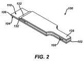
- FIG. 2is a simplified perspective view of the analytical test strip of FIG. 1 ;
- FIG. 3is a simplified perspective view of a distal portion of the analytical test strip of FIG. 1 in contact with test meter electrical connector pins;
- FIG. 4is a simplified side view of the distal portion of FIG. 3 ;
- FIG. 5is a top view of a patterned spacer layer of the analytical test strip of FIG. 1 ;
- FIG. 6is a top view of a third electrically conductive layer of the analytical test strip of FIG. 1 ;
- FIG. 7is a simplified top view of the analytical test strip of claim 1 with an integrated carrier sheet
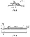
- FIG. 8is a simplified distal end view of the analytical test strip and integrated carrier sheet of FIG. 5
- FIG. 9is a simplified cross-sectional view of the analytical test strip and integrated carrier sheet of FIG. 5 ;
- FIG. 10is a flow diagram depicting stages in a method for determining an analyte in a bodily fluid sample according to an embodiment of the present invention.
- the terms “about” or “approximately” for any numerical values or rangesindicate a suitable dimensional tolerance that allows the part or collection of components to function for its intended purpose as described herein.
- analytical test strips for use with a test meterinclude a first insulating layer with a first insulating layer upper surface and a first electrically conductive layer disposed on the first insulating layer upper surface.
- the first electrically conductive layerincludes a first electrode portion (such as a working electrode portion) and an electrical contact pad in electrical communication with the first electrode portion.
- the analytical test stripsalso include a patterned spacer layer disposed above the first electrically conductive layer.
- the analytical test stripsfurther include a second insulating layer that is disposed above the patterned spacer layer and has a second insulating layer lower surface with a third electrically conductive layer disposed thereon.
- the third electrically conductive layerincludes a second electrode portion (such as, for example, a reference/counter electrode) and a proximal portion that overlies the interlayer contact portion.
- the second electrode portion of the analytical test stripsis disposed overlying and exposed to the sample-receiving chamber in an opposing (i.e., co-facial) relationship to the first electrode portion.
- the proximal portionis operatively juxtaposed with the interlayer contact portion such that there is an electrical connection between the second electrode portion of the third electrically conductive layer and the electrical contact pad of the patterned spacer layer during use of the analytical test strip.
- the electrical contact pad of the first electrically conductive layer and the electrical contact pad of the second electrically conductive layerare referred to as stacked unidirectional contact pads. They are “stacked” since the electrical contact pad of the second electrically conductive layer is elevated with respect to the electrical contact pad of the first electrically conductive layer. They are “unidirectional” since both are on upper surfaces and can, therefore, be accessed and contacted from the same direction.
- Analytical test strips according to the present inventionare beneficial in that, for example, their configuration and, in particular, the stacked unidirectional nature of the contact pads, is amenable to high-volume, high-yield mass production without dedicated and complex tight-alignment die cutting steps to expose the contact pads.
- FIG. 1is a simplified exploded perspective view of an analytical test strip 100 according to an embodiment of the present invention.
- FIG. 2is a simplified perspective view of the electrochemical-based analytical test strip of FIG. 1 .
- FIG. 3is a simplified perspective view of a portion of the electrochemical-based analytical test strip of FIG. 1 in contact with test meter electrical connector pins (ECP).
- FIG. 4is a simplified side view of the portion of FIG. 3 .
- FIG. 5is a top view of a patterned spacer layer of the analytical test strip of FIG. 1 .
- FIG. 6is a top view of a third electrically conductive layer of the analytical test strip of FIG. 1 .
- analytical test strip 100 for use with a test meter in the determination of an analyte (such as glucose) in a bodily fluid sampleincludes a first insulating layer 102 with a first insulating layer upper surface 104 and a first electrically conductive layer 106 disposed on first insulating upper surface 104 .
- First electrically conductive layer 106includes a first electrode portion 108 and an electrical contact pad 110 in electrical communication with first electrode portion 108 .
- Analytical test strip 100also includes a patterned spacer layer 112 disposed above first electrically conductive layer 106 .
- Patterned spacer layer 112has a distal portion 114 defining a bodily fluid sample-receiving chamber 116 therein that overlies first electrode portion 108 .
- Patterned spacer layer 112also has an insulating proximal portion 118 with an upper surface 120 and a second electrically conductive layer 122 disposed thereon.
- second electrically conductive layer 122has an interlayer contact portion 124 and an electrical contact pad 126 .
- Analytical test strip 100further includes a second insulating layer 128 disposed above patterned spacer layer 112 .
- Second insulating layer 128has a second insulating layer lower surface 130 .
- Analytical test strip 100yet further includes a third electrically conductive layer 132 disposed on second insulating layer lower surface 130 that includes a second electrode portion 134 and a proximal portion 136 that overlies interlayer contact portion 124 .
- Second electrode portion 134is disposed overlying and exposed to bodily fluid sample-receiving chamber 116 and in an opposing (i.e., co-facial) relationship to first electrode portion 108 .
- Analytical test strip 100also includes a reagent layer 138 (see FIG. 1 in particular).
- the proximal portion of the third electrically conductive layeris operatively juxtaposed with the interlayer contact portion of the second electrically conductive layer such that there is an electrical connection between the second electrode portion of the third electrically conductive layer and the electrical contact pad of the patterned spacer layer during use of the analytical test strip.
- This electrical connectionprovides for unidirectional stacked electrical contact pads even though the first and second electrode portions are in an opposing (i.e., co-facial) arrangement.
- the proximal portion of the third electrically conductive layercan be operatively juxtaposed with the inter layer contact portion by, for example, attachment with an electrically conductive adhesive or by compression of a gap therebetween (in the direction of arrow A of FIG. 4 ) upon insertion into the test meter.
- a compressioncan be achieved, for example, by the application of a force in the range of 3 pounds per square-inch to 30 pounds per square inch.
- the operative juxtapositioncan be provided by any known means including an electrically fused joint or an electrically conductive foil connection.
- Electrical contact pads 126 and 110are each configured to operatively interface with a test meter via electrical contact with separate electrical connector pins (labeled ECP in FIGS. 3 and 4 ) of the test meter.
- First insulating layer 102 , insulating proximal portion 118 , and second insulating layer 128can be formed, for example, of a plastic (e.g., PET, PETG, polyimide, polycarbonate, polystyrene), silicon, ceramic, or glass material.
- a plastice.g., PET, PETG, polyimide, polycarbonate, polystyrene
- the first and second insulating layerscan be formed from a 7 mil polyester substrate.
- first electrode portion 108 and second electrode portion 134are configured to electrochemically determine analyte concentration in a bodily fluid sample (such as glucose in a whole blood sample) using any suitable electrochemical-based technique known to one skilled in the art.
- the first, second and third electrically conductive layers, 106 , 122 and 132 respectively,can be formed of any suitable conductive material such as, for example, gold, palladium, carbon, silver, platinum, tin oxide, iridium, indium, or combinations thereof (e.g., indium doped tin oxide).
- any suitable techniquecan be employed to form the first, second and third conductive layers including, for example, sputtering, evaporation, electro-less plating, screen-printing, contact printing, or gravure printing.
- first electrically conductive layer 106can be a sputtered palladium layer
- third electrically conductive layer 132can be a sputtered gold layer.
- Patterned spacer layer 112can be, for example, a double-sided pressure sensitive adhesive layer, a heat activated adhesive layer, or a thermo-setting adhesive plastic layer. Patterned spacer layer 112 can have, for example, a thickness in the range of from about 50 micron to about 300 microns, preferably between about 75 microns and about 150 microns.
- the overall length of analytical test strip 100can be, for example, in the range of 30 mm to 50 mm and the width can be, for example, in the range of 2 mm to 5 mm.
- Reagent layer 134can be any suitable mixture of reagents that selectively react with an analyte such as, for example glucose, in a bodily fluid sample to form an electroactive species, which can then be quantitatively measured at an electrode of analyte test strips according to embodiments of the present invention. Therefore, reagent layer 138 can include at least a mediator and an enzyme. Examples of suitable mediators include ferricyanide, ferrocene, ferrocene derivatives, osmium bipyridyl complexes, and quinone derivatives.
- Suitable enzymesinclude glucose oxidase, glucose dehydrogenase (GDH) using a pyrroloquinoline quinone (PQQ) co-factor, GDH using a nicotinamide adenine dinucleotide (NAD) co-factor, and GDH using a flavin adenine dinucleotide (FAD) co-factor.
- Reagent layer 134can be formed using any suitable technique.
- analytical test strip 100can further include at least one integrated carrier sheet configured solely as a user handle.
- analytical test strip 100includes a first integrated carrier sheet 140 and a second integrated carrier sheet 142 .
- first integrated carrier sheet 140is configured such that the electrical contact pad of the first electrically conductive layer and the electrical contact pad of the patterned spacer layer are exposed. Such exposure enables electrical contact to a test meter during use.
- the first and second integrated carrier sheetscan be formed of any suitable material including, for example, paper, cardboard, or plastic materials. Since the first and second integrated carrier sheets are configured solely as a user handle in the present embodiments, they can be formed of relatively inexpensive materials.
- FIG. 10is a flow diagram depicting stages in a method 1000 for determining an analyte (such as glucose) in a bodily fluid sample (for example, a whole blood sample).
- Method 1000includes introducing a bodily fluid sample into a sample-receiving chamber of an analytical test strip that has a first electrode portion of a first electrically conductive layer and a second electrode portion of a third electrically conductive layer therein (see step 1010 of FIG. 10 ).
- the first electrode portion and the second electrode portionare in an opposing relationship.
- an electrical response of the first electrode portion and the second electrode portionis measured via an electrical contact pad of the first electrically conductive layer and via an electrical contact pad of a second electrically conductive layer of a patterned spacer layer of the analytical test strip.
- the patterned spacer layeris disposed between the first electrically conductive layer and the third electrically conductive layer.
- the electrical contact pad of the first electrically conductive layer and the second electrically conductive layerare configured in a unidirectional stacked relationship and the second electrode portion is in electrical communication with the electrical contact pad of the second electrically conductive layer.
- Method 1000also includes, at step 1030 , determining the analyte based on the measured electrical response.
- method 1000can be readily modified to incorporate any of the techniques, benefits and characteristics of analytical test strips according to embodiments of the present invention and described herein.
Landscapes
- Health & Medical Sciences (AREA)
- Life Sciences & Earth Sciences (AREA)
- Chemical & Material Sciences (AREA)
- Hematology (AREA)
- Immunology (AREA)
- Molecular Biology (AREA)
- General Health & Medical Sciences (AREA)
- General Physics & Mathematics (AREA)
- Pathology (AREA)
- Biochemistry (AREA)
- Analytical Chemistry (AREA)
- Physics & Mathematics (AREA)
- Engineering & Computer Science (AREA)
- Chemical Kinetics & Catalysis (AREA)
- Urology & Nephrology (AREA)
- Biomedical Technology (AREA)
- Biophysics (AREA)
- Electrochemistry (AREA)
- Medicinal Chemistry (AREA)
- Microbiology (AREA)
- Diabetes (AREA)
- Cell Biology (AREA)
- Biotechnology (AREA)
- Food Science & Technology (AREA)
- Investigating Or Analysing Biological Materials (AREA)
- Measurement Of The Respiration, Hearing Ability, Form, And Blood Characteristics Of Living Organisms (AREA)
Abstract
Description
Claims (5)
Priority Applications (25)
| Application Number | Priority Date | Filing Date | Title |
|---|---|---|---|
| US13/410,609US9217723B2 (en) | 2012-03-02 | 2012-03-02 | Co-facial analytical test strip with stacked unidirectional contact pads |
| US13/585,330US20130228475A1 (en) | 2012-03-02 | 2012-08-14 | Co-facial analytical test strip with stacked unidirectional contact pads and inert carrier substrate |
| PCT/EP2013/054216WO2013128021A1 (en) | 2012-03-02 | 2013-03-01 | Test strip with stacked unidirectional contact |
| EP13707615.4AEP2820143B1 (en) | 2012-03-02 | 2013-03-01 | Test strip with stacked unidirectional contact pads |
| RU2014139828ARU2014139828A (en) | 2012-03-02 | 2013-03-01 | TEST STRIP WITH MULTILAYERED ONE-DIRECTIONAL CONTACT SITE AND INERT CARRIER SUBSTRATE |
| PCT/EP2013/054222WO2013128026A1 (en) | 2012-03-02 | 2013-03-01 | Test strip with stacked unidirectional contact pads and inert carrier substrate |
| RU2014139824ARU2014139824A (en) | 2012-03-02 | 2013-03-01 | TEST STRIP WITH MULTILAYERED ONE-DIRECTIONAL CONTACT |
| JP2014559254AJP2015508900A (en) | 2012-03-02 | 2013-03-01 | Coplanar analysis test strip with stacked unidirectional contact pads |
| CA2865458ACA2865458C (en) | 2012-03-02 | 2013-03-01 | Test strip with stacked unidirectional contact |
| JP2014559257AJP2015508901A (en) | 2012-03-02 | 2013-03-01 | Coplanar analysis test strip with laminated unidirectional contact pads and inert support substrate |
| AU2013224918AAU2013224918B2 (en) | 2012-03-02 | 2013-03-01 | Test strip with stacked unidirectional contact |
| TW102107192ATWI583948B (en) | 2012-03-02 | 2013-03-01 | Co-facial analytical test strip with stacked unidirectional contact pads |
| CA2865459ACA2865459A1 (en) | 2012-03-02 | 2013-03-01 | Test strip with stacked unidirectional contact pads and inert carrier substrate |
| ES13707615.4TES2623505T3 (en) | 2012-03-02 | 2013-03-01 | Test strips with stacked unidirectional contact pads |
| CN201380012160.1ACN104160035B (en) | 2012-03-02 | 2013-03-01 | With the test strip for stacking unidirectional contact |
| TW102107191ATW201346256A (en) | 2012-03-02 | 2013-03-01 | Co-facial analytical test strip with stacked unidirectional contact pads and inert carrier substrate |
| EP13707170.0AEP2839020A1 (en) | 2012-03-02 | 2013-03-01 | Test strip with stacked unidirectional contact pads and inert carrier substrate |
| KR1020147027759AKR20140137410A (en) | 2012-03-02 | 2013-03-01 | Test strip with stacked unidirectional contact |
| IN7232DEN2014IN2014DN07232A (en) | 2012-03-02 | 2013-03-01 | |
| AU2013224847AAU2013224847B2 (en) | 2012-03-02 | 2013-03-01 | Test strip with stacked unidirectional contact pads and inert carrier substrate |
| KR1020147027754AKR20140137409A (en) | 2012-03-02 | 2013-03-01 | Test strip with stacked unidirectional contact pads and inert carrier substrate |
| IN7234DEN2014IN2014DN07234A (en) | 2012-03-02 | 2013-03-01 | |
| HK15106378.2AHK1205766B (en) | 2012-03-02 | 2013-03-01 | Test strip with stacked unidirectional contact pads |
| CN201380012191.7ACN104160036A (en) | 2012-03-02 | 2013-03-01 | Test strip with stacked unidirectional contact pads and inert carrier substrate |
| US14/939,135US20160069832A1 (en) | 2012-03-02 | 2015-11-12 | Co-facial analytical test strip with stacked unidirectional contact pads |
Applications Claiming Priority (1)
| Application Number | Priority Date | Filing Date | Title |
|---|---|---|---|
| US13/410,609US9217723B2 (en) | 2012-03-02 | 2012-03-02 | Co-facial analytical test strip with stacked unidirectional contact pads |
Related Child Applications (2)
| Application Number | Title | Priority Date | Filing Date |
|---|---|---|---|
| US13/585,330Continuation-In-PartUS20130228475A1 (en) | 2012-03-02 | 2012-08-14 | Co-facial analytical test strip with stacked unidirectional contact pads and inert carrier substrate |
| US14/939,135DivisionUS20160069832A1 (en) | 2012-03-02 | 2015-11-12 | Co-facial analytical test strip with stacked unidirectional contact pads |
Publications (2)
| Publication Number | Publication Date |
|---|---|
| US20130228474A1 US20130228474A1 (en) | 2013-09-05 |
| US9217723B2true US9217723B2 (en) | 2015-12-22 |
Family
ID=47827189
Family Applications (2)
| Application Number | Title | Priority Date | Filing Date |
|---|---|---|---|
| US13/410,609Expired - Fee RelatedUS9217723B2 (en) | 2012-03-02 | 2012-03-02 | Co-facial analytical test strip with stacked unidirectional contact pads |
| US14/939,135AbandonedUS20160069832A1 (en) | 2012-03-02 | 2015-11-12 | Co-facial analytical test strip with stacked unidirectional contact pads |
Family Applications After (1)
| Application Number | Title | Priority Date | Filing Date |
|---|---|---|---|
| US14/939,135AbandonedUS20160069832A1 (en) | 2012-03-02 | 2015-11-12 | Co-facial analytical test strip with stacked unidirectional contact pads |
Country Status (11)
| Country | Link |
|---|---|
| US (2) | US9217723B2 (en) |
| EP (1) | EP2820143B1 (en) |
| JP (1) | JP2015508900A (en) |
| KR (1) | KR20140137410A (en) |
| CN (1) | CN104160035B (en) |
| AU (1) | AU2013224918B2 (en) |
| CA (1) | CA2865458C (en) |
| ES (1) | ES2623505T3 (en) |
| IN (1) | IN2014DN07232A (en) |
| RU (1) | RU2014139824A (en) |
| WO (1) | WO2013128021A1 (en) |
Families Citing this family (11)
| Publication number | Priority date | Publication date | Assignee | Title |
|---|---|---|---|---|
| RU2598162C1 (en)* | 2012-09-07 | 2016-09-20 | Цилаг Гмбх Интернэшнл | Electrochemical sensors and method for production thereof |
| GB2518165B (en)* | 2013-09-11 | 2016-04-27 | Cilag Gmbh Int | Electrochemical-based analytical test strip with ultra-thin discontinuous metal layer |
| US20150096906A1 (en)* | 2013-10-07 | 2015-04-09 | Cilag Gmbh International | Biosensor with bypass electrodes |
| TW201716034A (en)* | 2015-11-13 | 2017-05-16 | 五鼎生物技術股份有限公司 | Biological test sheet |
| US10739296B2 (en) | 2017-05-24 | 2020-08-11 | Philosys Co., Ltd. | Test strip providing code sequence to be automatically recognized, and biological analyte monitoring device |
| KR102092325B1 (en)* | 2017-05-24 | 2020-03-23 | 주식회사 필로시스 | Test strip for providing code sequence automatically recognized and device to monitor biological analyte |
| US20190094170A1 (en)* | 2017-09-22 | 2019-03-28 | Cilag Gmbh International | Analytical test strip with integrated electrical resistor |
| US11333627B2 (en) | 2018-08-01 | 2022-05-17 | Dkl International, Inc. | Remote detector for dielectric material |
| US11300541B2 (en) | 2018-08-01 | 2022-04-12 | Dkl International, Inc. | Dynamic selective polarization matching for remote detection of smokeless gunpowder |
| US11462807B2 (en) | 2018-08-01 | 2022-10-04 | Dkl International, Inc. | Dynamic selective polarization matching |
| US11614474B2 (en)* | 2020-07-24 | 2023-03-28 | Dkl International, Inc. | Remote detection of animate entities |
Citations (26)
| Publication number | Priority date | Publication date | Assignee | Title |
|---|---|---|---|---|
| US5082626A (en) | 1988-08-08 | 1992-01-21 | Boehringer Mannheim Gmbh | Wedge shaped test strip system useful in analyzing test samples, such as whole blood |
| JPH1151895A (en) | 1997-07-31 | 1999-02-26 | Nok Corp | Biosensor |
| JPH1194817A (en) | 1997-09-17 | 1999-04-09 | Matsushita Electric Ind Co Ltd | Analysis equipment |
| US6071391A (en)* | 1997-09-12 | 2000-06-06 | Nok Corporation | Enzyme electrode structure |
| US6212417B1 (en) | 1998-08-26 | 2001-04-03 | Matsushita Electric Industrial Co., Ltd. | Biosensor |
| EP1347058A2 (en) | 2002-03-21 | 2003-09-24 | Roche Diagnostics GmbH | Electrochemical biosensor with connector windows |
| US20040020771A1 (en) | 2002-04-26 | 2004-02-05 | Yuko Taniike | Biosensor, adapter used therefor, and measuring device |
| US20040253367A1 (en) | 2003-06-12 | 2004-12-16 | Wogoman Frank W. | Sensor format and construction method for capillary-filled diagnostic sensors |
| US20050258035A1 (en) | 2004-05-21 | 2005-11-24 | Agamatrix, Inc. | Electrochemical Cell and Method of Making an Electrochemical Cell |
| EP1642646A1 (en) | 2004-09-30 | 2006-04-05 | Lifescan, Inc. | Microfluidic analytical system with accessible electrically conductive contact pads |
| US20060226985A1 (en) | 2005-02-08 | 2006-10-12 | Goodnow Timothy T | RF tag on test strips, test strip vials and boxes |
| US20070037057A1 (en) | 2005-08-12 | 2007-02-15 | Douglas Joel S | Non printed small volume in vitro analyte sensor and methods |
| US20070074977A1 (en) | 2005-09-30 | 2007-04-05 | Lifescan, Inc. | Method and apparatus for rapid electrochemical analysis |
| WO2007071562A1 (en) | 2005-12-19 | 2007-06-28 | F. Hoffmann La-Roche Ag | Sandwich sensor for the determination of an analyte concentration |
| US7343188B2 (en) | 2002-05-09 | 2008-03-11 | Lifescan, Inc. | Devices and methods for accessing and analyzing physiological fluid |
| US7390665B2 (en) | 2001-02-28 | 2008-06-24 | Gilmour Steven B | Distinguishing test types through spectral analysis |
| US20090024015A1 (en) | 2007-07-17 | 2009-01-22 | Edwards Lifesciences Corporation | Sensing element having an adhesive backing |
| US20090026074A1 (en)* | 2007-07-26 | 2009-01-29 | Sridhar Iyengar | Electrochemical test strips |
| US20090095623A1 (en) | 2007-10-10 | 2009-04-16 | Agamatrix, Inc. | Identification Method for Electrochemical Test Strips |
| US20090317297A1 (en)* | 2008-06-24 | 2009-12-24 | John Mahoney | Analyte test strip for accepting diverse sample volumes |
| US20090325205A1 (en) | 2008-06-16 | 2009-12-31 | Takaaki Fujii | Method for measuring analysis object, biosensor and measuring device |
| US20100017165A1 (en) | 2008-07-15 | 2010-01-21 | Bayer Healthcare Llc | Multi-Layered Biosensor Encoding Systems |
| US20110070634A1 (en) | 2008-05-26 | 2011-03-24 | Panasonic Corporation | Biosensor |
| WO2011049094A1 (en) | 2009-10-20 | 2011-04-28 | ニプロ株式会社 | Biosample detection device |
| EP2317315A1 (en) | 2009-10-27 | 2011-05-04 | Lifescan Scotland Limited | Dual chamber, multi-analyte test strip with opposing electrodes and body fluid test method using this strip |
| US7967140B2 (en) | 2005-01-10 | 2011-06-28 | Grossman Victor A | Packaging and dispensers for adhesive backed elements |
- 2012
- 2012-03-02USUS13/410,609patent/US9217723B2/ennot_activeExpired - Fee Related
- 2013
- 2013-03-01AUAU2013224918Apatent/AU2013224918B2/ennot_activeCeased
- 2013-03-01RURU2014139824Apatent/RU2014139824A/ennot_activeApplication Discontinuation
- 2013-03-01ESES13707615.4Tpatent/ES2623505T3/enactiveActive
- 2013-03-01ININ7232DEN2014patent/IN2014DN07232A/enunknown
- 2013-03-01KRKR1020147027759Apatent/KR20140137410A/ennot_activeCeased
- 2013-03-01JPJP2014559254Apatent/JP2015508900A/enactivePending
- 2013-03-01CNCN201380012160.1Apatent/CN104160035B/enactiveActive
- 2013-03-01WOPCT/EP2013/054216patent/WO2013128021A1/enactiveApplication Filing
- 2013-03-01EPEP13707615.4Apatent/EP2820143B1/enactiveActive
- 2013-03-01CACA2865458Apatent/CA2865458C/enactiveActive
- 2015
- 2015-11-12USUS14/939,135patent/US20160069832A1/ennot_activeAbandoned
Patent Citations (32)
| Publication number | Priority date | Publication date | Assignee | Title |
|---|---|---|---|---|
| US5082626A (en) | 1988-08-08 | 1992-01-21 | Boehringer Mannheim Gmbh | Wedge shaped test strip system useful in analyzing test samples, such as whole blood |
| JPH1151895A (en) | 1997-07-31 | 1999-02-26 | Nok Corp | Biosensor |
| US6071391A (en)* | 1997-09-12 | 2000-06-06 | Nok Corporation | Enzyme electrode structure |
| US20030102213A1 (en) | 1997-09-12 | 2003-06-05 | Therasense, Inc. | Biosensor |
| JPH1194817A (en) | 1997-09-17 | 1999-04-09 | Matsushita Electric Ind Co Ltd | Analysis equipment |
| US6212417B1 (en) | 1998-08-26 | 2001-04-03 | Matsushita Electric Industrial Co., Ltd. | Biosensor |
| CN1134659C (en) | 1998-08-26 | 2004-01-14 | 松下电器产业株式会社 | biological sensor |
| US7390665B2 (en) | 2001-02-28 | 2008-06-24 | Gilmour Steven B | Distinguishing test types through spectral analysis |
| EP1347058A2 (en) | 2002-03-21 | 2003-09-24 | Roche Diagnostics GmbH | Electrochemical biosensor with connector windows |
| US20040020771A1 (en) | 2002-04-26 | 2004-02-05 | Yuko Taniike | Biosensor, adapter used therefor, and measuring device |
| US7343188B2 (en) | 2002-05-09 | 2008-03-11 | Lifescan, Inc. | Devices and methods for accessing and analyzing physiological fluid |
| US20040253367A1 (en) | 2003-06-12 | 2004-12-16 | Wogoman Frank W. | Sensor format and construction method for capillary-filled diagnostic sensors |
| CN101424684A (en) | 2003-06-12 | 2009-05-06 | 拜尔健康护理有限责任公司 | Sensor format and construction method for capillary-filled diagnostic sensors |
| US20050258035A1 (en) | 2004-05-21 | 2005-11-24 | Agamatrix, Inc. | Electrochemical Cell and Method of Making an Electrochemical Cell |
| EP1642646A1 (en) | 2004-09-30 | 2006-04-05 | Lifescan, Inc. | Microfluidic analytical system with accessible electrically conductive contact pads |
| US7967140B2 (en) | 2005-01-10 | 2011-06-28 | Grossman Victor A | Packaging and dispensers for adhesive backed elements |
| US20060226985A1 (en) | 2005-02-08 | 2006-10-12 | Goodnow Timothy T | RF tag on test strips, test strip vials and boxes |
| US20070037057A1 (en) | 2005-08-12 | 2007-02-15 | Douglas Joel S | Non printed small volume in vitro analyte sensor and methods |
| US20070074977A1 (en) | 2005-09-30 | 2007-04-05 | Lifescan, Inc. | Method and apparatus for rapid electrochemical analysis |
| CN1975403A (en) | 2005-09-30 | 2007-06-06 | 生命扫描有限公司 | Method and apparatus for rapid electrochemical analysis |
| WO2007071562A1 (en) | 2005-12-19 | 2007-06-28 | F. Hoffmann La-Roche Ag | Sandwich sensor for the determination of an analyte concentration |
| US20090024015A1 (en) | 2007-07-17 | 2009-01-22 | Edwards Lifesciences Corporation | Sensing element having an adhesive backing |
| US20090026074A1 (en)* | 2007-07-26 | 2009-01-29 | Sridhar Iyengar | Electrochemical test strips |
| CN101779120A (en) | 2007-07-26 | 2010-07-14 | 埃葛梅崔克斯股份有限公司 | Electrochemical test strips |
| US20090095623A1 (en) | 2007-10-10 | 2009-04-16 | Agamatrix, Inc. | Identification Method for Electrochemical Test Strips |
| US20110070634A1 (en) | 2008-05-26 | 2011-03-24 | Panasonic Corporation | Biosensor |
| US20090325205A1 (en) | 2008-06-16 | 2009-12-31 | Takaaki Fujii | Method for measuring analysis object, biosensor and measuring device |
| US20090317297A1 (en)* | 2008-06-24 | 2009-12-24 | John Mahoney | Analyte test strip for accepting diverse sample volumes |
| EP2138846A1 (en) | 2008-06-24 | 2009-12-30 | Lifescan, Inc. | Analyte test strip for accepting diverse sample volumes |
| US20100017165A1 (en) | 2008-07-15 | 2010-01-21 | Bayer Healthcare Llc | Multi-Layered Biosensor Encoding Systems |
| WO2011049094A1 (en) | 2009-10-20 | 2011-04-28 | ニプロ株式会社 | Biosample detection device |
| EP2317315A1 (en) | 2009-10-27 | 2011-05-04 | Lifescan Scotland Limited | Dual chamber, multi-analyte test strip with opposing electrodes and body fluid test method using this strip |
Non-Patent Citations (6)
| Title |
|---|
| First Office Action issued in related Chinese Patent Application No. 201380012160.1, dated Aug. 5, 2015, 21 pages. |
| International Preliminary Report on Patentability issued in related International Patent Application No. PCT/EP2013/054216, mailed Sep. 12, 2014, 8 pages. |
| International Preliminary Report on Patentability issued in related International Patent Application No. PCT/EP2013/054222, mailed Sep. 12, 2014, 12 pages. |
| International Search Report, PCT Application No. PCT/EP2013/054216, dated May 7, 2013, 3 pages, European Patent Office, Rijswijk, Netherlands. |
| International Search Report, PCT Application No. PCT/EP2013/054222, dated May 3, 2013, 3 pages, European Patent Office, Rijswijk, Netherlands. |
| Search Report issued in related Chinese Patent Application No. 201380012160.1, dated Jul. 27, 2015, 2 pages. |
Also Published As
| Publication number | Publication date |
|---|---|
| JP2015508900A (en) | 2015-03-23 |
| KR20140137410A (en) | 2014-12-02 |
| US20160069832A1 (en) | 2016-03-10 |
| WO2013128021A1 (en) | 2013-09-06 |
| RU2014139824A (en) | 2016-04-20 |
| HK1205766A1 (en) | 2015-12-24 |
| AU2013224918A1 (en) | 2014-10-16 |
| CN104160035A (en) | 2014-11-19 |
| AU2013224918B2 (en) | 2018-11-15 |
| CA2865458C (en) | 2020-06-16 |
| EP2820143B1 (en) | 2017-03-01 |
| ES2623505T3 (en) | 2017-07-11 |
| US20130228474A1 (en) | 2013-09-05 |
| IN2014DN07232A (en) | 2015-04-24 |
| CN104160035B (en) | 2017-04-05 |
| EP2820143A1 (en) | 2015-01-07 |
| CA2865458A1 (en) | 2013-09-06 |
Similar Documents
| Publication | Publication Date | Title |
|---|---|---|
| US9217723B2 (en) | Co-facial analytical test strip with stacked unidirectional contact pads | |
| EP2308991B1 (en) | Multi-analyte test strip with inline working electrodes and shared opposing counter/reference electrode | |
| EP2317315B1 (en) | Dual chamber, multi-analyte test strip with opposing electrodes and body fluid test method using this strip | |
| EP2292785A1 (en) | Multi-analyte test strip with shared counter/reference electrode and inline electrode configuration | |
| US20130084591A1 (en) | Analytical test strip with isolated bodily fluid phase-shift and analyte determination sample chambers | |
| AU2013224847B2 (en) | Test strip with stacked unidirectional contact pads and inert carrier substrate | |
| US20130084590A1 (en) | Analytical test strip with bodily fluid phase-shift measurement electrodes | |
| HK1205766B (en) | Test strip with stacked unidirectional contact pads | |
| KR20110046304A (en) | Dual chamber multi-analyte test strip with opposite electrode | |
| AU2015264958A1 (en) | Analytical test strip with isolated bodily fluid phase-shift and analyte determination sample chambers | |
| KR20110046307A (en) | Test meter for use with a dual chamber, multi-analyte test strip with opposing electrodes | |
| HK1155809B (en) | Dual chamber, multi-analyte test strip with opposing electrodes and body fluid test method using this strip | |
| HK1154050A (en) | Multi-analyte test strip with shared counter/reference electrode and inline electrode configuration | |
| HK1155808A (en) | Test meter for use with dual chamber, multi-analyte test strip with opposing electrodes | |
| HK1155493B (en) | Multi-analyte test strip with inline working electrodes and shared opposing counter/reference electrode |
Legal Events
| Date | Code | Title | Description |
|---|---|---|---|
| AS | Assignment | Owner name:CILAG GMBH INTERNATIONAL, SWITZERLAND Free format text:ASSIGNMENT OF ASSIGNORS INTEREST;ASSIGNORS:SLOSS, SCOTT;BAIN, RUSSELL;WEBSTER, GRAEME;SIGNING DATES FROM 20120228 TO 20120301;REEL/FRAME:027796/0791 | |
| STCF | Information on status: patent grant | Free format text:PATENTED CASE | |
| AS | Assignment | Owner name:BANK OF AMERICA, N.A., AS COLLATERAL AGENT, NORTH CAROLINA Free format text:SECURITY AGREEMENT;ASSIGNOR:LIFESCAN IP HOLDINGS, LLC;REEL/FRAME:047179/0150 Effective date:20181001 Owner name:BANK OF AMERICA, N.A., AS COLLATERAL AGENT, NORTH Free format text:SECURITY AGREEMENT;ASSIGNOR:LIFESCAN IP HOLDINGS, LLC;REEL/FRAME:047179/0150 Effective date:20181001 | |
| AS | Assignment | Owner name:BANK OF AMERICA, N.A., AS COLLATERAL AGENT, NORTH CAROLINA Free format text:SECURITY AGREEMENT;ASSIGNOR:LIFESCAN IP HOLDINGS, LLC;REEL/FRAME:047186/0836 Effective date:20181001 Owner name:BANK OF AMERICA, N.A., AS COLLATERAL AGENT, NORTH Free format text:SECURITY AGREEMENT;ASSIGNOR:LIFESCAN IP HOLDINGS, LLC;REEL/FRAME:047186/0836 Effective date:20181001 | |
| MAFP | Maintenance fee payment | Free format text:PAYMENT OF MAINTENANCE FEE, 4TH YEAR, LARGE ENTITY (ORIGINAL EVENT CODE: M1551); ENTITY STATUS OF PATENT OWNER: LARGE ENTITY Year of fee payment:4 | |
| AS | Assignment | Owner name:LIFESCAN IP HOLDINGS, LLC, CALIFORNIA Free format text:ASSIGNMENT OF ASSIGNORS INTEREST;ASSIGNOR:CILAG GMBH INTERNATIONAL;REEL/FRAME:051050/0413 Effective date:20181001 | |
| AS | Assignment | Owner name:BANK OF AMERICA, N.A., NORTH CAROLINA Free format text:FIRST LIEN PATENT SECURITY AGREEMENT;ASSIGNOR:LIFESCAN IP HOLDINGS, LLC;REEL/FRAME:063712/0430 Effective date:20230519 | |
| AS | Assignment | Owner name:BANK OF AMERICA, N.A., NORTH CAROLINA Free format text:SECOND LIEN PATENT SECURITY AGREEMENT;ASSIGNOR:LIFESCAN IP HOLDINGS, LLC;REEL/FRAME:063740/0080 Effective date:20230519 | |
| AS | Assignment | Owner name:JOHNSON & JOHNSON CONSUMER INC., NEW JERSEY Free format text:RELEASE OF SECOND LIEN PATENT SECURITY AGREEMENT RECORDED OCT. 3, 2018, REEL/FRAME 047186/0836;ASSIGNOR:BANK OF AMERICA, N.A.;REEL/FRAME:064206/0176 Effective date:20230627 Owner name:JANSSEN BIOTECH, INC., PENNSYLVANIA Free format text:RELEASE OF SECOND LIEN PATENT SECURITY AGREEMENT RECORDED OCT. 3, 2018, REEL/FRAME 047186/0836;ASSIGNOR:BANK OF AMERICA, N.A.;REEL/FRAME:064206/0176 Effective date:20230627 Owner name:LIFESCAN IP HOLDINGS, LLC, CALIFORNIA Free format text:RELEASE OF SECOND LIEN PATENT SECURITY AGREEMENT RECORDED OCT. 3, 2018, REEL/FRAME 047186/0836;ASSIGNOR:BANK OF AMERICA, N.A.;REEL/FRAME:064206/0176 Effective date:20230627 | |
| FEPP | Fee payment procedure | Free format text:MAINTENANCE FEE REMINDER MAILED (ORIGINAL EVENT CODE: REM.); ENTITY STATUS OF PATENT OWNER: LARGE ENTITY | |
| LAPS | Lapse for failure to pay maintenance fees | Free format text:PATENT EXPIRED FOR FAILURE TO PAY MAINTENANCE FEES (ORIGINAL EVENT CODE: EXP.); ENTITY STATUS OF PATENT OWNER: LARGE ENTITY | |
| STCH | Information on status: patent discontinuation | Free format text:PATENT EXPIRED DUE TO NONPAYMENT OF MAINTENANCE FEES UNDER 37 CFR 1.362 | |
| FP | Lapsed due to failure to pay maintenance fee | Effective date:20231222 |