US9217497B2 - Push chain, linear motion driving device and patient table - Google Patents
Push chain, linear motion driving device and patient tableDownload PDFInfo
- Publication number
- US9217497B2 US9217497B2US13/572,002US201213572002AUS9217497B2US 9217497 B2US9217497 B2US 9217497B2US 201213572002 AUS201213572002 AUS 201213572002AUS 9217497 B2US9217497 B2US 9217497B2
- Authority
- US
- United States
- Prior art keywords
- push
- chain
- strip
- mounting
- piece
- Prior art date
- Legal status (The legal status is an assumption and is not a legal conclusion. Google has not performed a legal analysis and makes no representation as to the accuracy of the status listed.)
- Expired - Fee Related, expires
Links
Images


Classifications
- F—MECHANICAL ENGINEERING; LIGHTING; HEATING; WEAPONS; BLASTING
- F16—ENGINEERING ELEMENTS AND UNITS; GENERAL MEASURES FOR PRODUCING AND MAINTAINING EFFECTIVE FUNCTIONING OF MACHINES OR INSTALLATIONS; THERMAL INSULATION IN GENERAL
- F16H—GEARING
- F16H19/00—Gearings comprising essentially only toothed gears or friction members and not capable of conveying indefinitely-continuing rotary motion
- F16H19/02—Gearings comprising essentially only toothed gears or friction members and not capable of conveying indefinitely-continuing rotary motion for interconverting rotary or oscillating motion and reciprocating motion
- F16H19/06—Gearings comprising essentially only toothed gears or friction members and not capable of conveying indefinitely-continuing rotary motion for interconverting rotary or oscillating motion and reciprocating motion comprising flexible members, e.g. an endless flexible member
- F16H19/0636—Gearings comprising essentially only toothed gears or friction members and not capable of conveying indefinitely-continuing rotary motion for interconverting rotary or oscillating motion and reciprocating motion comprising flexible members, e.g. an endless flexible member the flexible member being a non-buckling chain
- B—PERFORMING OPERATIONS; TRANSPORTING
- B66—HOISTING; LIFTING; HAULING
- B66F—HOISTING, LIFTING, HAULING OR PUSHING, NOT OTHERWISE PROVIDED FOR, e.g. DEVICES WHICH APPLY A LIFTING OR PUSHING FORCE DIRECTLY TO THE SURFACE OF A LOAD
- B66F3/00—Devices, e.g. jacks, adapted for uninterrupted lifting of loads
- B66F3/02—Devices, e.g. jacks, adapted for uninterrupted lifting of loads with racks actuated by pinions
- B66F3/06—Devices, e.g. jacks, adapted for uninterrupted lifting of loads with racks actuated by pinions with racks comprising pivotable toothed sections or segments, e.g. arranged in pairs
- F—MECHANICAL ENGINEERING; LIGHTING; HEATING; WEAPONS; BLASTING
- F16—ENGINEERING ELEMENTS AND UNITS; GENERAL MEASURES FOR PRODUCING AND MAINTAINING EFFECTIVE FUNCTIONING OF MACHINES OR INSTALLATIONS; THERMAL INSULATION IN GENERAL
- F16G—BELTS, CABLES, OR ROPES, PREDOMINANTLY USED FOR DRIVING PURPOSES; CHAINS; FITTINGS PREDOMINANTLY USED THEREFOR
- F16G13/00—Chains
- F16G13/18—Chains having special overall characteristics
- F16G13/20—Chains having special overall characteristics stiff; Push-pull chains
- F—MECHANICAL ENGINEERING; LIGHTING; HEATING; WEAPONS; BLASTING
- F16—ENGINEERING ELEMENTS AND UNITS; GENERAL MEASURES FOR PRODUCING AND MAINTAINING EFFECTIVE FUNCTIONING OF MACHINES OR INSTALLATIONS; THERMAL INSULATION IN GENERAL
- F16H—GEARING
- F16H7/00—Gearings for conveying rotary motion by endless flexible members
- F16H7/06—Gearings for conveying rotary motion by endless flexible members with chains
- Y—GENERAL TAGGING OF NEW TECHNOLOGICAL DEVELOPMENTS; GENERAL TAGGING OF CROSS-SECTIONAL TECHNOLOGIES SPANNING OVER SEVERAL SECTIONS OF THE IPC; TECHNICAL SUBJECTS COVERED BY FORMER USPC CROSS-REFERENCE ART COLLECTIONS [XRACs] AND DIGESTS
- Y10—TECHNICAL SUBJECTS COVERED BY FORMER USPC
- Y10T—TECHNICAL SUBJECTS COVERED BY FORMER US CLASSIFICATION
- Y10T74/00—Machine element or mechanism
- Y10T74/18—Mechanical movements
- Y10T74/18056—Rotary to or from reciprocating or oscillating
- Y10T74/18088—Rack and pinion type
- Y10T74/18096—Shifting rack
Definitions
- the present embodimentsrelate to the field of driving technology.
- Linear motion driving devicesmay be used in many mechanical structures, and the sprocket/push-chain driving device is one of these.
- Sprocket/push-chain driving devicesmay include a push-chain, a sprocket and a guiding component.
- One end of the push-chainhas a connecting part, and another end of the push-chain passes around the sprocket and is placed freely.
- the guiding componentis in contact with the push-chain and is used to guide the push-chain to move in a set linear direction.
- the sprocket/push-chain driving devicesmay also include a push-chain box for accommodating the sprocket and the freely placed end of the push-chain.
- the Chinese patent application with application no. 20082013537.4discloses a vertical motion driving device of the sprocket/push-chain type for a patient table.
- this vertical motion driving deviceincludes a push-chain 1 , a sprocket 2 , guiding components 3 and a push-chain box 4 .
- the section of the push-chain 1 that is arranged in the vertical directionis used to support a bed board of the patient table.
- the sprocket 2 and the push-chain 1are meshed with one another.
- the sprocket 2is capable of driving the push-chain 1 to move when the sprocket 2 rotates, such that the push-chain 1 drives the bed board in up/down vertical motion under the action of the guiding components.
- Chinese patent application no. 20082000631.4discloses a horizontal motion driving device of the sprocket/push-chain type for a patient table.
- This devicesimilarly includes a sprocket, a push-chain, guiding components, and a push-chain box.
- One end of the push-chainhas a connecting part for connecting to the bed board of the patient table, while the other end passes around the sprocket and is placed freely.
- the sprocketrotates, the sprocket drives the push-chain in reciprocal horizontal motion, thereby making the push-chain drive the bed board in reciprocal horizontal motion under the action of the guiding components.
- the present embodimentsmay obviate one or more of the drawbacks or limitations in the related art.
- a push-chainthat reduces cost and increases the effective travel of the push-chain is provided.
- Each push-chain link of the plurality of push-chain linksincludes two strip-shaped mounting pieces disposed opposite one another and one connecting piece that connects at most half of an end face of the two mounting pieces at one side.
- Each of the two mounting piecesis provided with two mounting holes in the longitudinal direction. A distance between the two mounting holes is equal to half the length of the mounting piece.
- the mounting holes on the two mounting piecesare arranged opposite one another, and two corners on another side of each of the two mounting pieces are rounded corners allowing the push-chain to bend.
- Two adjacent push-chain links of the plurality of push-chain linksare hinge-connected in a horizontally staggered arrangement by way of a chain pivot and the mounting holes.
- connection between the connecting piece and the mounting pieceforms a filleted corner.
- connection between the connecting piece and the mounting pieceforms a right angle.
- a bearingis also installed on the chain pivot.
- the width of a middle portion of the connecting pieceis less than or equal to half the length of the mounting piece.
- the width of both end portions of the connecting pieceis slightly narrower than the width of the middle portion in accordance with a set range.
- a linear motion driving deviceincludes a sprocket, a guiding component, and a push-chain in any one of the above-described forms of implementation.
- One end of the push-chainhas a connecting part, and another end of the push-chain passes around the sprocket and is placed freely.
- the guiding componentis in contact with the push-chain and is used to guide the push-chain to move in a set linear direction.
- the linear motion driving devicefurther includes a push-chain box for accommodating the sprocket and the push-chain.
- a long U-shaped guiding structureis provided inside the push-chain box.
- the long U-shapedallows the push-chain to extend along the long U-shaped guiding structure after passing around the sprocket so as to bend around at another end of the push-chain box, forming two parallel layers.
- the devicefurther includes a driver for driving the sprocket to rotate in forward and reverse directions.
- One embodiment of a patient tableincludes a linear motion driving device in any of the above-described forms of implementation.
- a bed board of the patient tableis connected to the push-chain connecting part in the linear motion driving device.
- a whole push-chainmay be assembled from push-chain links of the same shape and full assembly of a single section of chain requires only two of the same push-chain links and one chain pivot (e.g., three functional components in total), the number of types of components used by the whole chain is greatly reduced compared to the prior art.
- the universal nature of the componentsresults in a large reduction in the cost of the chain.
- the space of one section of chainis provided for the turning radius of the chain, which is a reduction of a third compared to the prior art.
- the space of the push-chain boxis correspondingly reduced, and the effective travel of the push-chain is correspondingly increased.
- FIG. 1is a structural schematic diagram of a vertical motion driving device of the sprocket/push-chain type in the prior art
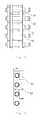
- FIGS. 2 a to 2 dare structural schematic diagrams of embodiments of a push-chain in the embodiments of the present invention.
- FIG. 3is a structural schematic diagram of one embodiment of a linear motion driving device.
- FIGS. 2 a to 2 dare structural schematic diagrams of embodiments of a push-chain.
- FIG. 2 ais a three-dimensional drawing of the push-chain
- FIG. 2 b and FIG. 2 care a two-dimensional main view and a two-dimensional right view of the push-chain, respectively
- FIG. 2 dis a structural schematic diagram of one push-chain link of the push-chain.
- one embodiment of a push-chain 5includes a plurality of push-chain links 51 .
- Each push-chain link of the plurality of push-chain links 51includes two strip-shaped mounting pieces 511 (e.g., mounting pieces) disposed opposite one another and a connecting piece 512 (e.g., one connecting piece) that connects, at most, half of an end face of the two mounting pieces 511 at one side.
- Each of the two mounting pieces 511is provided with two mounting holes 5111 in the length direction. A distance between the two mounting holes 5111 is equal to half the length of the mounting piece 511 .
- a mounting hole 5111may be provided both at one quarter and at three quarters of the length of the mounting piece 511 .
- the mounting holes 5111 on the two mounting pieces 511are arranged opposite one another, and two corners 5112 and 5113 on the other side of each of the two mounting pieces 511 are rounded corners allowing the push-chain to bend.
- Two adjacent push-chain links of the plurality of push-chain links 51are hinge-connected in a horizontally staggered arrangement by way of a chain pivot 52 and the mounting holes 5111 .
- a bearing 53(e.g., a needle roller bearing) may also be installed on the chain pivot 52 .
- each push-chain link of the plurality of push-chain links 51may be formed as a single unit.
- the single unitmay be formed by machining a steel plate, by casting, or by another method.
- each push-chain link of the plurality of push-chain links 51may be formed by connecting independent elements together.
- the mounting pieces 511 and the connecting piece 512may be connected by such methods as, for example, welding or riveting to form the push-chain link 51 .
- connection between the mounting pieces 511 and the connecting pieces 512may form a filleted corner or a right angle.
- the connecting piece 512may have a structure that is slightly wider in the middle and slightly narrower at the two ends. In other words, the width of a middle portion of the connecting piece 512 is less than or equal to half the length of the mounting piece 511 , while the width of two end portions of the connecting piece 512 is slightly narrower than the width of the middle portion in accordance with a set range.
- a single section of chainmay be fully assembled from just two identical push-chain links and one chain pivot.
- a bearingis also installed on the chain pivot.
- the positions of two push-chain linksare in a horizontally staggered arrangement and are separated in the vertical direction by a distance of one chain pivot section.
- Such an assemblyallows each section of chain to be connected to the next.
- the number of types of components used by the whole chainis greatly reduced compared to the prior art, while the universal nature of the components results in a large reduction in the cost of the chain.
- the space of just one section of chainis used for the turning radius of the chain, so that the space used by the push-chain in terms of push-chain box space is smaller.
- FIG. 3is a structural schematic diagram of one embodiment of a linear motion driving device.
- the linear motion driving deviceincludes a sprocket 6 , a guiding component 7 , a push-chain box 8 , and one embodiment of a push-chain 5 (e.g., in any one of the forms of implementation described above).
- One end of the push-chain 5has a connecting part 54 .
- Another end of the push-chainpasses around the sprocket 6 and is placed freely.
- the guiding component 7is in contact with the push-chain 5 and is used to guide the push-chain 5 to move in a set linear direction.
- FIG. 3takes the vertical direction as an example for description but in actual applications, the linear direction may also be the horizontal direction.
- the push-chain box 8is used to accommodate the sprocket 6 and the push-chain 5 .
- a long U-shaped guiding structureis provided inside the push-chain box 8 . This allows the push-chain 5 to extend along the long U-shaped guiding structure after passing around the sprocket 6 so as to bend around at another end of the push-chain box 8 , forming two parallel layers.
- the push-chain box 8may be omitted in some actual applications.
- the guiding component 7includes a first guide rail piece 71 and a second guide rail piece 72 located on the two sides of the push-chain 5 and for guiding the push-chain 5 to move in a vertical direction.
- the sprocket 6drives the push-chain 5 in linear motion in the exit direction of the first guide rail piece 71 and second guide rail piece 72 , and the chain pivots 52 of the push-chain 5 are able to maintain linear motion in the same direction continuously under the guiding action of the first guide rail piece 71 and the second guide rail piece 72 .
- the assembly structure of the push-chain 5provides that the bending of the push-chain 5 may only occur in one direction, while vertically adjacent push-chain links of the plurality of push-chain links 51 may have two different contact faces on the left and the right therebetween. This may allow the stress on the push-chain 5 in a direction of motion to be distributed equally between the left and right contact faces.
- This way of bearing stressmay achieve an anti-bending function in a similar way to a frame, such that in the direction of motion, a single section of chain may not develop a tendency to bend.
- the connecting part 54 at the end of the chainstays in the same direction as that of the guide rail pieces 71 and 72 , the push-chain 5 will not bend during movement and long-travel linear motion may be achieved.
- the space of the push-chain box 8is not limited, the maximum movement length of the push-chain 5 may not be limited.
- the linear motion driving device in this embodimentmay also include a driver (not shown in the figures) for driving the sprocket 6 to rotate in forward and reverse directions and thereby drive the push-chain 5 to move.
- the drivermay be implemented using a variety of devices such as, for example, an electric motor.
- the motormay be directly connected to the sprocket 6 or may be connected via a transmission mechanism (not shown in the figures).
- the transmission mechanismis connected to the motor and to the sprocket 6 .
- the transmission mechanismmay include a gearbox that is connected to the sprocket 6 and to the motor either directly or via a rubber belt. When the rubber belt is used to connect the motor to the gearbox, one end of the rubber belt is looped around a belt wheel of the motor, while another end of the rubber belt is looped around a belt wheel of the gearbox.
- a medical apparatusincludes a linear motion driving device in any of the above-described forms of implementation.
- the linear motionmay be vertical motion or horizontal motion.
- a bed board of a patient tablemay be connected to the push-chain connecting part in the linear motion driving device.
- a speed reduction gearboxmay be used as the gearbox.
- the speed reduction gearboxmay drive the sprocket to rotate with a lower speed, thereby providing that the speed of lifting and lowering of the patient table is not too fast.
- the patient tablemay thus be easily controlled to move to a precise position.
Landscapes
- Engineering & Computer Science (AREA)
- General Engineering & Computer Science (AREA)
- Mechanical Engineering (AREA)
- Life Sciences & Earth Sciences (AREA)
- Geology (AREA)
- Structural Engineering (AREA)
- Transmission Devices (AREA)
- Apparatus For Radiation Diagnosis (AREA)
Abstract
Description
Claims (18)
Applications Claiming Priority (3)
| Application Number | Priority Date | Filing Date | Title |
|---|---|---|---|
| CN201120291050.1 | 2011-08-11 | ||
| CN2011202910501UCN202176674U (en) | 2011-08-11 | 2011-08-11 | Push chain, linear motion drive device and examination couch |
| CN201120291050U | 2011-08-11 |
Publications (2)
| Publication Number | Publication Date |
|---|---|
| US20130205926A1 US20130205926A1 (en) | 2013-08-15 |
| US9217497B2true US9217497B2 (en) | 2015-12-22 |
Family
ID=45866554
Family Applications (1)
| Application Number | Title | Priority Date | Filing Date |
|---|---|---|---|
| US13/572,002Expired - Fee RelatedUS9217497B2 (en) | 2011-08-11 | 2012-08-10 | Push chain, linear motion driving device and patient table |
Country Status (3)
| Country | Link |
|---|---|
| US (1) | US9217497B2 (en) |
| CN (1) | CN202176674U (en) |
| DE (1) | DE102012214270B4 (en) |
Cited By (2)
| Publication number | Priority date | Publication date | Assignee | Title |
|---|---|---|---|---|
| USD906621S1 (en)* | 2017-02-21 | 2020-12-29 | Evoqua Water Technologies Llc | Hollow chain link pin |
| US11358842B2 (en)* | 2017-01-10 | 2022-06-14 | Serapid—France | Thrust chain device |
Families Citing this family (15)
| Publication number | Priority date | Publication date | Assignee | Title |
|---|---|---|---|---|
| CN102644718B (en)* | 2012-04-09 | 2015-04-22 | 中国核电工程有限公司 | Open transmission chain push-and-pull mechanism |
| CN103573944A (en)* | 2012-07-26 | 2014-02-12 | 康立 | Multistage double-speed parallel reciprocating mechanism |
| CN104337538A (en)* | 2013-07-24 | 2015-02-11 | 上海联影医疗科技有限公司 | Retractable supporting structure and hospital bed lifting mechanism |
| DE102014103164B4 (en) | 2014-03-10 | 2022-05-25 | Baker Hughes Digital Solutions Gmbh | Chain with elastic back strap |
| DE102014007458B4 (en) | 2014-05-21 | 2017-07-20 | Grob GmbH | push chain |
| JP2019094911A (en)* | 2016-03-29 | 2019-06-20 | ライフロボティクス株式会社 | Linear motion expandable mechanism robot arm mechanism |
| NO343196B1 (en)* | 2016-04-20 | 2018-11-26 | Optimar As | Apparatus for filling and emptying horizontal freezers and freezing system comprising one or more apparatus for emptying and filling horizontal freezers. |
| DE102016111542B4 (en)* | 2016-06-23 | 2022-04-28 | Iwis Antriebssysteme Gmbh & Co. Kg | Linear chain with standardized end piece |
| CN109250642A (en)* | 2017-07-13 | 2019-01-22 | 宁波路佳机械科技有限公司 | Tower folds chain |
| DE102018104768A1 (en)* | 2018-03-02 | 2019-09-05 | Iwis Antriebssysteme Gmbh & Co. Kg | Actuator with back stiff chain |
| US10935106B2 (en) | 2018-06-14 | 2021-03-02 | Serapid, Inc. | Block chain with monolithic links |
| CN109268460B (en)* | 2018-11-20 | 2024-01-05 | 宁波益捷精密机械有限公司 | Rigid chain push-pull actuating mechanism |
| DE102022108095B3 (en) | 2022-04-05 | 2023-03-16 | Grob GmbH | linear chain |
| CN115301889A (en)* | 2022-08-02 | 2022-11-08 | 湖北昊鑫自动化设备科技有限公司 | Tank chain equipment is with mechanism of advancing |
| CN117383166A (en)* | 2023-12-01 | 2024-01-12 | 青岛征和工业股份有限公司 | A multi-directional horizontal push chain transmission device |
Citations (27)
| Publication number | Priority date | Publication date | Assignee | Title |
|---|---|---|---|---|
| US2048131A (en)* | 1934-04-16 | 1936-07-21 | George L Curtis | Adjusting hardware for sashes and the like |
| DE650777C (en) | 1934-04-21 | 1937-10-04 | Peter Mallmann | Load lifter |
| DE1890452U (en) | 1964-01-25 | 1964-04-02 | Bundesbahn Bundesbahn Zentrala | ROLLABLE, SELF-SUPPORTING ARM. |
| US3289811A (en)* | 1965-02-12 | 1966-12-06 | J B Ehrsam & Sons Mfg Company | Registry maintenance for stackedboard transfer |
| US4227421A (en)* | 1978-03-20 | 1980-10-14 | Weishew Joseph F | Carriage reciprocator and positioner with continuously moving chain |
| US4272952A (en)* | 1979-05-08 | 1981-06-16 | Dresser Industries, Inc. | Plastic chain and tubular link pin |
| US4297840A (en)* | 1979-10-01 | 1981-11-03 | C. L. Frost & Son, Inc. | Chain link and chain assembly including same |
| US4625507A (en)* | 1984-02-28 | 1986-12-02 | Kabelschlepp Gesellschaft Mit Beschrankter Haftung | Guide chain |
| US4672805A (en)* | 1985-03-01 | 1987-06-16 | Kabelschlepp Gesellschaft Mit Beschrankter Haftung | Guide chain for guiding energy lines |
| US6065278A (en)* | 1995-12-01 | 2000-05-23 | Kabelschlepp Gmbh | Chain link of an energy guide chain with additional body |
| DE20102310U1 (en) | 2001-02-02 | 2001-04-26 | Arnold & Stolzenberg GmbH, 37574 Einbeck | Back stiff chain |
| US6315688B1 (en)* | 1998-09-10 | 2001-11-13 | Sram Corporation | Derailleur link |
| DE10137939A1 (en) | 2001-08-07 | 2003-03-06 | Alfons Huber | Thrust chain to be driven by sprocket has single chain links with forked ennd anr projecting element |
| US20030177752A1 (en)* | 2002-03-19 | 2003-09-25 | Takerou Nakagawa | Wear resistant chain |
| WO2004006597A1 (en) | 2002-07-09 | 2004-01-15 | Siemens Aktiengesellschaft | Avoidance of transcoding or interruption on live load coding exchange in extant connections |
| US20040185978A1 (en)* | 2001-02-14 | 2004-09-23 | Prince Jeffrey Theorin | Chain with selectively engaged links |
| US7017328B2 (en)* | 2003-11-13 | 2006-03-28 | Tsubakimoto Chain Co. | Cable protection and guide device |
| US7056246B2 (en)* | 2003-10-24 | 2006-06-06 | Borgwarner Inc. | Compliant chain guide with multiple joints |
| US7167739B2 (en)* | 2001-10-29 | 2007-01-23 | Koninklijke Philips Electronics N.V. | Assembly of medical examination device and a combination of a frame and a patient table as well as such a combination |
| US20080202868A1 (en)* | 2007-02-23 | 2008-08-28 | Gunderson Llc | Handbrake linkage for a railroad freight car |
| US20080271429A1 (en)* | 2007-05-02 | 2008-11-06 | Shoichiro Komiya | Cable protection and guide device |
| CN201150539Y (en) | 2008-01-31 | 2008-11-19 | 上海西门子医疗器械有限公司 | Horizontal movement device for examining bed |
| US20090008615A1 (en)* | 2007-06-07 | 2009-01-08 | High Arctic Energy Services Limited Partnership | Roller chain and sprocket system |
| CN201308591Y (en) | 2008-08-25 | 2009-09-16 | 上海西门子医疗器械有限公司 | Sickbed vertical movement driving device |
| US7669401B2 (en)* | 2005-04-28 | 2010-03-02 | Kabelschelpp GmbH | Method and device for producing a chain |
| US20100320061A1 (en)* | 2009-06-19 | 2010-12-23 | Timothy Saunders | Track with overlapping links for dry coal extrusion pumps |
| US8695320B2 (en)* | 2011-02-04 | 2014-04-15 | Zike, Llc | Non-back-bending chain |
Family Cites Families (1)
| Publication number | Priority date | Publication date | Assignee | Title |
|---|---|---|---|---|
| DE2147186A1 (en)* | 1971-09-22 | 1973-03-29 | Miag Muehlenbau & Ind Gmbh | LIFTING DEVICE |
- 2011
- 2011-08-11CNCN2011202910501Upatent/CN202176674U/ennot_activeExpired - Lifetime
- 2012
- 2012-08-10DEDE201210214270patent/DE102012214270B4/ennot_activeExpired - Fee Related
- 2012-08-10USUS13/572,002patent/US9217497B2/ennot_activeExpired - Fee Related
Patent Citations (29)
| Publication number | Priority date | Publication date | Assignee | Title |
|---|---|---|---|---|
| US2048131A (en)* | 1934-04-16 | 1936-07-21 | George L Curtis | Adjusting hardware for sashes and the like |
| DE650777C (en) | 1934-04-21 | 1937-10-04 | Peter Mallmann | Load lifter |
| DE1890452U (en) | 1964-01-25 | 1964-04-02 | Bundesbahn Bundesbahn Zentrala | ROLLABLE, SELF-SUPPORTING ARM. |
| US3289811A (en)* | 1965-02-12 | 1966-12-06 | J B Ehrsam & Sons Mfg Company | Registry maintenance for stackedboard transfer |
| US4227421A (en)* | 1978-03-20 | 1980-10-14 | Weishew Joseph F | Carriage reciprocator and positioner with continuously moving chain |
| US4272952A (en)* | 1979-05-08 | 1981-06-16 | Dresser Industries, Inc. | Plastic chain and tubular link pin |
| US4297840A (en)* | 1979-10-01 | 1981-11-03 | C. L. Frost & Son, Inc. | Chain link and chain assembly including same |
| US4625507A (en)* | 1984-02-28 | 1986-12-02 | Kabelschlepp Gesellschaft Mit Beschrankter Haftung | Guide chain |
| US4672805A (en)* | 1985-03-01 | 1987-06-16 | Kabelschlepp Gesellschaft Mit Beschrankter Haftung | Guide chain for guiding energy lines |
| US6065278A (en)* | 1995-12-01 | 2000-05-23 | Kabelschlepp Gmbh | Chain link of an energy guide chain with additional body |
| US6315688B1 (en)* | 1998-09-10 | 2001-11-13 | Sram Corporation | Derailleur link |
| DE20102310U1 (en) | 2001-02-02 | 2001-04-26 | Arnold & Stolzenberg GmbH, 37574 Einbeck | Back stiff chain |
| US20040185978A1 (en)* | 2001-02-14 | 2004-09-23 | Prince Jeffrey Theorin | Chain with selectively engaged links |
| DE10137939A1 (en) | 2001-08-07 | 2003-03-06 | Alfons Huber | Thrust chain to be driven by sprocket has single chain links with forked ennd anr projecting element |
| US7167739B2 (en)* | 2001-10-29 | 2007-01-23 | Koninklijke Philips Electronics N.V. | Assembly of medical examination device and a combination of a frame and a patient table as well as such a combination |
| US20030177752A1 (en)* | 2002-03-19 | 2003-09-25 | Takerou Nakagawa | Wear resistant chain |
| WO2004006597A1 (en) | 2002-07-09 | 2004-01-15 | Siemens Aktiengesellschaft | Avoidance of transcoding or interruption on live load coding exchange in extant connections |
| ATE325512T1 (en) | 2002-07-09 | 2006-06-15 | Siemens Ag | AVOIDING TRANSCODING OR ABSORPTION DURING PAYLOAD CODING CHANGES IN EXISTING CONNECTIONS |
| US7056246B2 (en)* | 2003-10-24 | 2006-06-06 | Borgwarner Inc. | Compliant chain guide with multiple joints |
| US7017328B2 (en)* | 2003-11-13 | 2006-03-28 | Tsubakimoto Chain Co. | Cable protection and guide device |
| US7669401B2 (en)* | 2005-04-28 | 2010-03-02 | Kabelschelpp GmbH | Method and device for producing a chain |
| US20080202868A1 (en)* | 2007-02-23 | 2008-08-28 | Gunderson Llc | Handbrake linkage for a railroad freight car |
| US20080271429A1 (en)* | 2007-05-02 | 2008-11-06 | Shoichiro Komiya | Cable protection and guide device |
| US7591128B2 (en)* | 2007-05-02 | 2009-09-22 | Tsubakimoto Chain Co. | Cable protection and guide device |
| US20090008615A1 (en)* | 2007-06-07 | 2009-01-08 | High Arctic Energy Services Limited Partnership | Roller chain and sprocket system |
| CN201150539Y (en) | 2008-01-31 | 2008-11-19 | 上海西门子医疗器械有限公司 | Horizontal movement device for examining bed |
| CN201308591Y (en) | 2008-08-25 | 2009-09-16 | 上海西门子医疗器械有限公司 | Sickbed vertical movement driving device |
| US20100320061A1 (en)* | 2009-06-19 | 2010-12-23 | Timothy Saunders | Track with overlapping links for dry coal extrusion pumps |
| US8695320B2 (en)* | 2011-02-04 | 2014-04-15 | Zike, Llc | Non-back-bending chain |
Non-Patent Citations (1)
| Title |
|---|
| German Office Action dated Dec. 23, 2014 for corresponding DE 10 2012 214 270.3, with English Translation. |
Cited By (3)
| Publication number | Priority date | Publication date | Assignee | Title |
|---|---|---|---|---|
| US11358842B2 (en)* | 2017-01-10 | 2022-06-14 | Serapid—France | Thrust chain device |
| USD906621S1 (en)* | 2017-02-21 | 2020-12-29 | Evoqua Water Technologies Llc | Hollow chain link pin |
| USD1022376S1 (en) | 2017-02-21 | 2024-04-09 | Evoqua Water Technologies Llc | Hollow chain link pin |
Also Published As
| Publication number | Publication date |
|---|---|
| DE102012214270A1 (en) | 2013-02-14 |
| CN202176674U (en) | 2012-03-28 |
| US20130205926A1 (en) | 2013-08-15 |
| DE102012214270B4 (en) | 2015-05-13 |
Similar Documents
| Publication | Publication Date | Title |
|---|---|---|
| US9217497B2 (en) | Push chain, linear motion driving device and patient table | |
| US10301123B2 (en) | Transfer device | |
| US8984975B2 (en) | Engagement chain unit | |
| JP6706745B2 (en) | Transfer device | |
| US8967005B2 (en) | Engagement chain type device for forward and backward movement operation | |
| US8776491B2 (en) | Lifting engagement chain unit | |
| KR101929722B1 (en) | Engaging chain and movable body moving device | |
| JP2012225439A (en) | Engagement chain unit | |
| TW201544732A (en) | 3D push-pull chain | |
| US20100050802A1 (en) | Ball screw module | |
| JP4618743B2 (en) | Chain transmission | |
| KR200470208Y1 (en) | Rolling apparatus for welding of cylinder type structure | |
| JP2015055309A (en) | Chain driving device | |
| JP2008050072A (en) | Access device | |
| CN211323723U (en) | Movable chassis and compact shelf | |
| CN104414805B (en) | Lifting system | |
| JP6038707B2 (en) | Engagement chain type lifting device | |
| JP4662502B2 (en) | Meshing chain | |
| KR101099096B1 (en) | Guide Support | |
| US8973737B2 (en) | Conveying apparatus | |
| JP5494850B2 (en) | Linear motion device | |
| JP2009523111A5 (en) | ||
| JP5343513B2 (en) | Linear motion device | |
| US9273722B2 (en) | Rolling guide device | |
| JP6322422B2 (en) | Actuator |
Legal Events
| Date | Code | Title | Description |
|---|---|---|---|
| AS | Assignment | Owner name:SIEMENS AKTIENGESELLSCHAFT, GERMANY Free format text:ASSIGNMENT OF ASSIGNORS INTEREST;ASSIGNOR:SIEMENS SHANGHAI MEDICAL EQUIPMENT LTD.;REEL/FRAME:029497/0472 Effective date:20121022 Owner name:SIEMENS SHANGHAI MEDICAL EQUIPMENT LTD., CHINA Free format text:ASSIGNMENT OF ASSIGNORS INTEREST;ASSIGNORS:HUANG, JIAN;LIU, JIAN;WANG, YUN PING;REEL/FRAME:029497/0480 Effective date:20120903 | |
| FEPP | Fee payment procedure | Free format text:PAYOR NUMBER ASSIGNED (ORIGINAL EVENT CODE: ASPN); ENTITY STATUS OF PATENT OWNER: LARGE ENTITY | |
| STCF | Information on status: patent grant | Free format text:PATENTED CASE | |
| AS | Assignment | Owner name:SIEMENS HEALTHCARE GMBH, GERMANY Free format text:ASSIGNMENT OF ASSIGNORS INTEREST;ASSIGNOR:SIEMENS AKTIENGESELLSCHAFT;REEL/FRAME:039271/0561 Effective date:20160610 | |
| MAFP | Maintenance fee payment | Free format text:PAYMENT OF MAINTENANCE FEE, 4TH YEAR, LARGE ENTITY (ORIGINAL EVENT CODE: M1551); ENTITY STATUS OF PATENT OWNER: LARGE ENTITY Year of fee payment:4 | |
| FEPP | Fee payment procedure | Free format text:MAINTENANCE FEE REMINDER MAILED (ORIGINAL EVENT CODE: REM.); ENTITY STATUS OF PATENT OWNER: LARGE ENTITY | |
| LAPS | Lapse for failure to pay maintenance fees | Free format text:PATENT EXPIRED FOR FAILURE TO PAY MAINTENANCE FEES (ORIGINAL EVENT CODE: EXP.); ENTITY STATUS OF PATENT OWNER: LARGE ENTITY | |
| STCH | Information on status: patent discontinuation | Free format text:PATENT EXPIRED DUE TO NONPAYMENT OF MAINTENANCE FEES UNDER 37 CFR 1.362 | |
| FP | Lapsed due to failure to pay maintenance fee | Effective date:20231222 |