US9217337B2 - Adjustable engine mount - Google Patents
Adjustable engine mountDownload PDFInfo
- Publication number
- US9217337B2 US9217337B2US13/468,072US201213468072AUS9217337B2US 9217337 B2US9217337 B2US 9217337B2US 201213468072 AUS201213468072 AUS 201213468072AUS 9217337 B2US9217337 B2US 9217337B2
- Authority
- US
- United States
- Prior art keywords
- engine
- link
- failsafe
- mount
- case
- Prior art date
- Legal status (The legal status is an assumption and is not a legal conclusion. Google has not performed a legal analysis and makes no representation as to the accuracy of the status listed.)
- Active, expires
Links
Images


Classifications
- F—MECHANICAL ENGINEERING; LIGHTING; HEATING; WEAPONS; BLASTING
- F01—MACHINES OR ENGINES IN GENERAL; ENGINE PLANTS IN GENERAL; STEAM ENGINES
- F01D—NON-POSITIVE DISPLACEMENT MACHINES OR ENGINES, e.g. STEAM TURBINES
- F01D25/00—Component parts, details, or accessories, not provided for in, or of interest apart from, other groups
- F01D25/28—Supporting or mounting arrangements, e.g. for turbine casing
- F—MECHANICAL ENGINEERING; LIGHTING; HEATING; WEAPONS; BLASTING
- F02—COMBUSTION ENGINES; HOT-GAS OR COMBUSTION-PRODUCT ENGINE PLANTS
- F02C—GAS-TURBINE PLANTS; AIR INTAKES FOR JET-PROPULSION PLANTS; CONTROLLING FUEL SUPPLY IN AIR-BREATHING JET-PROPULSION PLANTS
- F02C7/00—Features, components parts, details or accessories, not provided for in, or of interest apart form groups F02C1/00 - F02C6/00; Air intakes for jet-propulsion plants
- F02C7/20—Mounting or supporting of plant; Accommodating heat expansion or creep
- B64D2027/262—
- B64D2027/266—
- B64D2027/268—
- B—PERFORMING OPERATIONS; TRANSPORTING
- B64—AIRCRAFT; AVIATION; COSMONAUTICS
- B64D—EQUIPMENT FOR FITTING IN OR TO AIRCRAFT; FLIGHT SUITS; PARACHUTES; ARRANGEMENT OR MOUNTING OF POWER PLANTS OR PROPULSION TRANSMISSIONS IN AIRCRAFT
- B64D27/00—Arrangement or mounting of power plants in aircraft; Aircraft characterised by the type or position of power plants
- B64D27/40—Arrangements for mounting power plants in aircraft
- B64D27/404—Suspension arrangements specially adapted for supporting vertical loads
- B—PERFORMING OPERATIONS; TRANSPORTING
- B64—AIRCRAFT; AVIATION; COSMONAUTICS
- B64D—EQUIPMENT FOR FITTING IN OR TO AIRCRAFT; FLIGHT SUITS; PARACHUTES; ARRANGEMENT OR MOUNTING OF POWER PLANTS OR PROPULSION TRANSMISSIONS IN AIRCRAFT
- B64D27/00—Arrangement or mounting of power plants in aircraft; Aircraft characterised by the type or position of power plants
- B64D27/40—Arrangements for mounting power plants in aircraft
- B64D27/406—Suspension arrangements specially adapted for supporting thrust loads, e.g. thrust links
- Y—GENERAL TAGGING OF NEW TECHNOLOGICAL DEVELOPMENTS; GENERAL TAGGING OF CROSS-SECTIONAL TECHNOLOGIES SPANNING OVER SEVERAL SECTIONS OF THE IPC; TECHNICAL SUBJECTS COVERED BY FORMER USPC CROSS-REFERENCE ART COLLECTIONS [XRACs] AND DIGESTS
- Y02—TECHNOLOGIES OR APPLICATIONS FOR MITIGATION OR ADAPTATION AGAINST CLIMATE CHANGE
- Y02T—CLIMATE CHANGE MITIGATION TECHNOLOGIES RELATED TO TRANSPORTATION
- Y02T50/00—Aeronautics or air transport
- Y02T50/60—Efficient propulsion technologies, e.g. for aircraft
- Y02T50/671—
Definitions
- This disclosurerelates to an engine mount for a gas turbine engine that includes an adjustable attachment feature.
- Gas turbine enginesare mounted to a pylon using a forward engine mount and an aft engine mount.
- the forward engine mountis mounted to a compressor case using a shackle with two connection points.
- the shacklereacts to both vertical and lateral loads between the engine and the pylon.
- the shackleis comprised of two identically shaped plates that are attached to each other such that a crack cannot propagate from one plate to the other, which satisfies a failsafe requirement for the shackle.
- the compressor caseincludes two case holes that are to be aligned with two corresponding shackle holes in the two plates. Fasteners or pins are then installed in the aligned holes.
- the case holes and shackle holesare drilled and reamed as required to maintain fit specifications. In order to maintain interchangeability between the two connecting components, the position tolerance of the holes cannot accumulate to more than the minimum clearance allowed at the pinned joint. This is a tight requirement with significant associated cost.
- the diameter of the holes in the case and/or shacklecould be increased for a “loose” fit; however, this would result in a structural and weight penalty.
- the pinsare not tightly held within the holes due to the “loose” fit, one of the pins will be subjected to all of the engine's lateral loads before the other pin.
- the case and the shacklewill then need to deform by a certain amount until the second pin banks against an edge of its hole and begins to share the load. This results in an unequal load share, which requires that the case lugs be designed for a high load, and thus have a higher weight.
- shackleis made from two plates to prevent crack propagation
- additional failsafe requirementsmay not be met by the stacked two plate configuration. For example, a failure in one of the engine case lugs will compromise the vertical and lateral load paths.
- a forward engine mount assembly for a gas turbine engineincludes a mount beam having a main body with a fore end and an aft end, and a forward shackle assembly supported by the fore end of the mount beam and comprising a first link configured to be connected to a first engine case structure and a second link configured to be connected to a second engine case structure, the first and second links being pivotally attached to each other.
- the first and second linkseach include at least a first hole for connection to a respective one of the first and second engine case structures and a second hole configured to receive a pin extending outwardly from the fore end of the mount beam that pivotally connects the first and second links.
- the first and second case structurescomprise mounting lugs with holes configured to receive pins to secure the first and second links to an engine outer casing.
- the first and second linkseach include a third hole configured to receive a failsafe pin extending outwardly from the fore end of the mount beam.
- the second holeis positioned between the first and third holes on each link body of the first and second links.
- one of the first and second linksincludes a slot to receive a portion of the other of the first and second links.
- first and second linksare pivotally connected to each other with a pin that extends transversely through the slot.
- the first linkcomprises a first link body having a first case connection hole and a first beam connection hole and the second link comprises a second link body having a second case connection hole and a second beam connection hole.
- the first and second case connection holesare spaced apart from each other and the first and second beam connection holes are aligned with each other.
- the first link bodyincludes a first failsafe hole and the second link body includes a second failsafe hole that is aligned with the first failsafe hole.
- the first link bodyincludes a first end with the first case connection hole.
- the first link bodycomprises a first body portion and a second body portion spaced apart from the first body portion by a gap, each of the first and second body portions including aligned first beam connection holes and aligned first failsafe holes.
- the second link bodyis positioned within the gap such that the second failsafe hole is aligned with the first failsafe holes and the second beam connection hole is aligned with the first beam connection holes.
- a first thrust rod pivotally connected to the aft end of the mount beamis included and is configured for connection to an engine outer case adjacent the first engine case structure and a second thrust rod pivotally connected to the aft end of the mount beam and configured for connection to an engine outer case adjacent the second engine case structure.
- a gas turbine enginehas an engine outer case, a rear engine mount configured to attach the engine outer case to an aircraft support structure, and a forward engine mount configured to attach the engine outer case to the aircraft support structure.
- the forward engine mounthas a mount beam having a main body with a fore end and an aft end, a forward shackle assembly supported by the fore end of the mount beam and comprising a first link connected to the engine outer case at a first attachment interface and a second link connected to the engine outer case at a second attachment interface, the first and second links being pivotally attached to each other, and first and second thrust rods connected to the aft end of the main body and to the engine outer case.
- the main bodyincludes a pin extending outwardly from the fore end.
- the first linkcomprises a first link body having a first case connection hole and a first beam connection hole and the second link comprises a second link body having a second case connection hole and a second beam connection hole.
- the first and second case connection holesare spaced apart from each other and the first and second beam connection holes are aligned with each other and fit onto the pin.
- the pincomprises a main mount pin.
- the main bodyincludes a failsafe pin extending outwardly from the fore end of the main body and spaced apart from the main mount pin.
- the first link bodyincludes a first failsafe hole and the second link body includes a second failsafe hole that is aligned with the first failsafe hole.
- the failsafe pinis fit into the first and second failsafe holes.
- the first link bodyincludes a first end with the first case connection hole.
- the first link bodyextends from the first end and separates into a first portion and a second portion spaced apart from the first portion by a gap, each of the first and second portions including aligned first beam connection holes and aligned first failsafe holes.
- the second link bodyis positioned within the gap such that the second failsafe hole is aligned with the first failsafe holes and the second beam connection hole is aligned with the first beam connection holes.
- the failsafe pinbanks against an edge of the first and second failsafe holes when one of the first or second attachment interfaces experiences a failure.
- first and second attachment interfacescomprise first and second mounting lugs on the engine outer case.
- a first pinis included that connects the first link to the first mounting lug and a second pin that connects the second link to the second mounting lug.
- the forward shackle assemblyincludes a failsafe feature that allows vertical and lateral loads to be carried through one of the first and second links in light of a failure experienced by the other of the first and second links.
- the failsafe featurehas a first failsafe hole in the first link and a second failsafe hole in the second link, the first and second failsafe holes being aligned with each other and received on a failsafe pin of the mount beam.
- FIG. 1schematically illustrates a gas turbine engine with a mounting configuration.
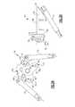
- FIG. 2Ais perspective view of a forward mount assembly.
- FIG. 2Bis a side view of the forward mount assembly of FIG. 2A .
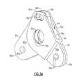
- FIG. 3Ais a perspective view of a shackle assembly of the forward mount assembly of FIG. 2A .
- FIG. 3Bshows first and second links of the shackle assembly in an unassembled state.
- FIG. 4Ais an end view of the shackle assembly of FIG. 3 .
- FIG. 4Bis a side view of the shackle assembly of FIG. 3 .
- FIG. 4Cis a cross-sectional view as indicated in FIG. 4A .
- FIG. 5shows a schematic illustration of a pin connection interface for each link to an engine outer case.
- FIG. 1schematically illustrates a gas turbine engine 20 that generally incorporates a fan section 22 , a compressor section 24 , a combustor section 26 and a turbine section 28 .
- Alternative enginesmight include an augmentor section (not shown) among other systems or features.
- the fan section 22drives air along a bypass flowpath B while the compressor section 24 drives air along a core flowpath C for compression and communication into the combustor section 26 then expansion through the turbine section 28 .
- the core airflow Cis compressed by the compressor section 24 , mixed and burned with fuel in the combustor section 26 , and then expanded over the turbine section 28 .
- the turbine 28 sectionrotationally drives a plurality of spools (not shown) in response to the expansion.
- a mounting arrangement 30is positioned between the gas turbine engine 20 and a rigid structure 32 of an attachment strut that is fixed to an aircraft wing (not shown) as known.
- the mounting arrangement 30includes a forward engine mount assembly 34 and a rearward engine mount assembly 36 that connect to the rigid structure 32 .
- the rigid structure 32includes a pyramid portion 38 or similar structure that extends to connect to the forward engine mount assembly 34 .
- the forward engine mount assembly 34 and the rearward engine mount assembly 36attach to an engine outer casing 40 .
- the rearward engine mount assembly 36comprises a rear mount beam 42 having an upper portion that is attached to the rigid structure 32 and a lower portion that is connected to mounting lugs 44 on the engine outer casing 40 with pins 46 .
- This is just one example of a rearward engine mount assembly 36and it should be understood that other rear mount configurations could also be used.
- FIGS. 2A-2Bshow the forward engine mount assembly 34 in greater detail.
- the forward engine mount assembly 34includes a front mount beam 50 having a main body 52 with a fore end 54 and an aft end 56 .
- the main body 52includes a generally flat upper surface 58 that mounts to the pyramid portion 38 .
- the main body 52can comprise a single-piece structure or can be comprised of two separate pieces that are attached to each other such that a crack cannot propagate from one piece to the other.
- the front mount beam 50includes a main pin 60 formed with the main body 52 and extending outwardly from the fore end 54 of the main body 52 .
- a failsafe pin 62is also formed with the main body 52 and extends outwardly from the fore end 54 of the main body 52 .
- the main pin 60is positioned vertically below the failsafe pin 62 and has a larger diameter than the failsafe pin 62 .
- the main pin 60 and failsafe pin 62each extend at an obtuse angle relative to a generally flat end face defined at the fore end 54 of the main body 52 .
- a rear pin 64is formed with the main body 52 and extends outwardly from the aft end 56 of the main body 52 .
- the rear pin 64connects a rudder bar 66 to the main body 52 as known.
- the rudder bar 66includes a first end 68 and a second end 70 that are on opposite sides of the main body 52 from each other.
- a first thrust rod 72is pivotally connected to the first end 68 and a second thrust rod 74 is pivotally connected to the second end 70 of the rudder bar 66 .
- the first and second thrust rods 72 , 74extend in a forward direction to connect to the engine outer case 40 (see FIG. 1 ) as known.
- a forward shackle assembly 76is supported by the fore end 54 of the mount beam 50 .
- the forward shackle assembly 76includes a first link 78 and a second link 80 that are pivotally attached to each other.
- the first link 78comprises a first link body 78 a having a first case connection hole 78 b and a first beam connection hole 78 c .
- the second link 80comprises a second link body 80 a having a second case connection hole 80 b and a second beam connection hole 80 c .
- the first 78 b and second 80 b case connection holesare spaced apart from each other to define a first attachment interface 82 and a second attachment interface 84 ( FIG. 2A ) to the engine outer case 40 ( FIG. 1 ), and the first 78 c and second 80 c beam connection holes are aligned with each other.
- the main pin 60is fit through the aligned beam connection holes 78 c , 80 c.
- a first fastener or pin 86is fit through the first case connection hole 78 b and a second fastener or pin 88 is fit through the second case connection hole 80 b .
- the pins 86 , 88connect to associated case holes 90 in mounting lugs 92 (only one is shown as an example) formed on the engine outer case 40 as shown in FIG. 5 .
- the first link body 78 aalso includes a first failsafe hole 78 d and the second link body 80 a includes a second failsafe hole 80 d that is aligned with the first failsafe hole 78 d when the links 78 , 80 are assembled.
- the aligned failsafe holes 78 d , 80 dare fit onto the failsafe pin 62 .
- the failsafe holes 78 d , 80 dcomprise an elongated slot having an ovoid shape or kidney shape such that the failsafe pin 62 is easily assembled through the failsafe holes 78 d , 80 d without interference. This comprises a failsafe feature that does not come into effect, i.e. does not experience loading, unless there is a failure event.
- the link engaged with the remaining pin at the first 82 or second 84 attachment interfacewill rotate until the failsafe pin 62 banks against one end of the slot. Vertical and lateral loads can then be carried through the one linked side of the shackle assembly 76 .
- the failsafe holes 78 d , 80 dcould comprise various shapes including an oversized circular hole, for example.
- the first link 78comprises a slotted link that receives a portion of the second link 80 in a nested or overlapping arrangement.
- the first link body 78 aincludes a first end 78 e with the first case connection hole 78 b and then extends to a second end 78 f that includes the first failsafe hole 78 d .
- the first beam connection hole 78 cis positioned generally between the first case connection hole 78 b and the first failsafe hole 78 d .
- first link body 78 aextends away from the first end 78 e , the body separates into a first body portion 78 g and a second body portion 78 h that is spaced apart from the first body portion 78 g by a gap or slot 94 .
- Each of the first 78 g and second 78 h body portionsinclude first beam connection holes 78 c that are aligned with each other and first failsafe holes 78 d that are aligned with each other.
- a bottom surface 96 of the slot 94is positioned to allow for sufficient adjustment of the second link 80 relative to the first link 78 , mount beam 50 , and case holes 90 during assembly.
- the first link 78can comprise a single-piece component, or as best shown in FIG. 3A , the first link 78 can be formed from two separate identical plates that are attached to each other. This configuration would result in the first case connection hole comprising a pair of holes 78 b , one in each plate, that are aligned with each other.
- the second link body 80 aincludes a portion that is positioned within the slot 94 such that the second failsafe hole 80 d is aligned with the first failsafe holes 78 d in the first 78 g and second 78 h body portions and the second beam connection hole 80 c is aligned with the first beam connection holes 78 c in the first 78 g and second 78 h body portions.
- the second link 80comprises a generally solid link with the second link body 80 a including a first end 80 e and a second end 80 f .
- the first end 80 eincludes the second case connection hole 80 b and extends to the second end 80 f that includes the second failsafe hole 80 d .
- the second beam connection hole 80 cis positioned generally between the second case connection hole 80 b and the second failsafe hole 80 d.
- the forward shackle assembly 76comprises a scissor link configuration where one link attaches to a right hand case lug 92 and the other link attaches to a left hand case lug 92 .
- the first 78 and second 80 linksrotate relative to each other to accommodate variations in hole size for the case holes 90 in the lugs 92 .
- the slot 94is sized to allow for the relative variation.
- This shackle assembly 76significantly reduces cost as the tolerance requirements for both the shackle and the engine case have been relaxed. Due to the two link configuration, loads are more equally shared between the case lug than in prior configurations, which also results in a weight reduction. Further, failsafe requirements are more fully satisfied as a failsafe alternative load path is provided by the failsafe holes and failsafe pin connection.
Landscapes
- Engineering & Computer Science (AREA)
- Mechanical Engineering (AREA)
- General Engineering & Computer Science (AREA)
- Chemical & Material Sciences (AREA)
- Combustion & Propulsion (AREA)
- Load-Engaging Elements For Cranes (AREA)
- Vibration Prevention Devices (AREA)
- Arrangement Or Mounting Of Propulsion Units For Vehicles (AREA)
Abstract
Description
Claims (19)
Priority Applications (2)
| Application Number | Priority Date | Filing Date | Title |
|---|---|---|---|
| US13/468,072US9217337B2 (en) | 2012-05-10 | 2012-05-10 | Adjustable engine mount |
| PCT/US2013/039818WO2014021966A2 (en) | 2012-05-10 | 2013-05-07 | Adjustable engine mount |
Applications Claiming Priority (1)
| Application Number | Priority Date | Filing Date | Title |
|---|---|---|---|
| US13/468,072US9217337B2 (en) | 2012-05-10 | 2012-05-10 | Adjustable engine mount |
Publications (2)
| Publication Number | Publication Date |
|---|---|
| US20130302157A1 US20130302157A1 (en) | 2013-11-14 |
| US9217337B2true US9217337B2 (en) | 2015-12-22 |
Family
ID=49548736
Family Applications (1)
| Application Number | Title | Priority Date | Filing Date |
|---|---|---|---|
| US13/468,072Active2034-10-23US9217337B2 (en) | 2012-05-10 | 2012-05-10 | Adjustable engine mount |
Country Status (2)
| Country | Link |
|---|---|
| US (1) | US9217337B2 (en) |
| WO (1) | WO2014021966A2 (en) |
Cited By (6)
| Publication number | Priority date | Publication date | Assignee | Title |
|---|---|---|---|---|
| US9784129B2 (en) | 2014-08-01 | 2017-10-10 | Pratt & Whitney Canada Corp. | Rear mount assembly for gas turbine engine |
| US20190152615A1 (en)* | 2017-11-21 | 2019-05-23 | Airbus Operations Sas | Rear engine attachment for an aircraft engine |
| US10829233B2 (en)* | 2016-12-30 | 2020-11-10 | Airbus Operations Sas | Engine assembly for an aircraft comprising a front engine attachment which facilitates its assembly |
| US11440670B2 (en)* | 2017-12-20 | 2022-09-13 | Safran Aircraft Engines | Suspension device |
| US11939070B2 (en) | 2020-02-21 | 2024-03-26 | General Electric Company | Engine-mounting links that have an adjustable inclination angle |
| US11970279B2 (en) | 2020-02-21 | 2024-04-30 | General Electric Company | Control system and methods of controlling an engine-mounting link system |
Families Citing this family (8)
| Publication number | Priority date | Publication date | Assignee | Title |
|---|---|---|---|---|
| FR3000529B1 (en)* | 2012-12-28 | 2015-03-06 | Airbus Operations Sas | FLEXIBLE BONDING DEVICE FOR AN AIRCRAFT PROPULSIVE ASSEMBLY |
| WO2016003534A2 (en)* | 2014-05-02 | 2016-01-07 | Sikorsky Aircraft Corporation | Articulated mounts |
| US9783312B2 (en)* | 2014-07-10 | 2017-10-10 | Honeywell International Inc. | Method and apparatus for reducing high transient mount load in aircraft engine mounting systems |
| FR3072078B1 (en)* | 2017-10-05 | 2021-06-11 | Airbus Operations Sas | REAR ENGINE ATTACHMENT FOR AN AIRCRAFT ENGINE |
| FR3093995A1 (en)* | 2019-03-18 | 2020-09-25 | Airbus Operations (S.A.S.) | Rear engine attachment of an aircraft having a reduced overall width and aircraft comprising at least one such rear engine attachment |
| US20210070459A1 (en)* | 2019-09-05 | 2021-03-11 | Spirit Aerosystems, Inc. | Mounting system for aircraft engine |
| FR3114129B1 (en)* | 2020-09-14 | 2022-08-05 | Safran Aircraft Engines | ASSEMBLY COMPRISING AN AIRCRAFT TURBOMACHINE AND ITS ATTACHMENT PYLONE |
| FR3125798A1 (en) | 2021-07-28 | 2023-02-03 | Airbus Operations | PROPULSION ASSEMBLY FOR AIRCRAFT COMPRISING A TURBOJET, A MAST AND MEANS FOR ATTACHING THE TURBOJET TO THE MAST |
Citations (17)
| Publication number | Priority date | Publication date | Assignee | Title |
|---|---|---|---|---|
| DE1481644B1 (en)* | 1965-08-20 | 1974-10-17 | Secr Defence | Suspension of a gas turbine engine on an airframe |
| US3979087A (en) | 1975-07-02 | 1976-09-07 | United Technologies Corporation | Engine mount |
| US5259183A (en)* | 1991-06-19 | 1993-11-09 | Societe Nationale D'etude Et De Construction De Moteurs D'aviation "S.N.E.C.M.A." | Turbojet engine exhaust casing with integral suspension lugs |
| US5275357A (en) | 1992-01-16 | 1994-01-04 | General Electric Company | Aircraft engine mount |
| US6330995B1 (en) | 2000-02-29 | 2001-12-18 | General Electric Company | Aircraft engine mount |
| US6607165B1 (en) | 2002-06-28 | 2003-08-19 | General Electric Company | Aircraft engine mount with single thrust link |
| US6843449B1 (en) | 2004-02-09 | 2005-01-18 | General Electric Company | Fail-safe aircraft engine mounting system |
| EP1103463B1 (en) | 1999-11-20 | 2005-06-29 | ROLLS-ROYCE plc | A gas turbine engine mounting arrangement |
| US20080169378A1 (en) | 2005-03-18 | 2008-07-17 | Airbus France | Engine Fastener Of A Mounting System Interposed Between An Attachment Strut And An Aircraft Engine |
| US20090184197A1 (en) | 2008-01-18 | 2009-07-23 | Cloft Thomas G | Pylon and engine mount configuration |
| US20090308078A1 (en) | 2008-06-11 | 2009-12-17 | Rolls-Royce Plc | Engine mounting apparatus |
| US20100170980A1 (en) | 2007-06-20 | 2010-07-08 | Airbus Operations | Engine mounting structure for aircraft with a rear engine attachment beam forming a spreader beam |
| US7909302B2 (en) | 2005-09-28 | 2011-03-22 | Airbus France | Two-shackle aircraft engine attachment |
| US8074923B2 (en) | 2008-04-24 | 2011-12-13 | Rolls-Royce Plc | Engine mounting apparatus |
| US20120018575A1 (en) | 2009-01-26 | 2012-01-26 | Whiteford Gerald P | Aircraft engine mounting system and method of mounting aircraft engines |
| US8128021B2 (en) | 2008-06-02 | 2012-03-06 | United Technologies Corporation | Engine mount system for a turbofan gas turbine engine |
| US8152094B2 (en) | 2008-06-11 | 2012-04-10 | Rolls-Royce Plc | Engine mounting apparatus |
- 2012
- 2012-05-10USUS13/468,072patent/US9217337B2/enactiveActive
- 2013
- 2013-05-07WOPCT/US2013/039818patent/WO2014021966A2/enactiveApplication Filing
Patent Citations (17)
| Publication number | Priority date | Publication date | Assignee | Title |
|---|---|---|---|---|
| DE1481644B1 (en)* | 1965-08-20 | 1974-10-17 | Secr Defence | Suspension of a gas turbine engine on an airframe |
| US3979087A (en) | 1975-07-02 | 1976-09-07 | United Technologies Corporation | Engine mount |
| US5259183A (en)* | 1991-06-19 | 1993-11-09 | Societe Nationale D'etude Et De Construction De Moteurs D'aviation "S.N.E.C.M.A." | Turbojet engine exhaust casing with integral suspension lugs |
| US5275357A (en) | 1992-01-16 | 1994-01-04 | General Electric Company | Aircraft engine mount |
| EP1103463B1 (en) | 1999-11-20 | 2005-06-29 | ROLLS-ROYCE plc | A gas turbine engine mounting arrangement |
| US6330995B1 (en) | 2000-02-29 | 2001-12-18 | General Electric Company | Aircraft engine mount |
| US6607165B1 (en) | 2002-06-28 | 2003-08-19 | General Electric Company | Aircraft engine mount with single thrust link |
| US6843449B1 (en) | 2004-02-09 | 2005-01-18 | General Electric Company | Fail-safe aircraft engine mounting system |
| US20080169378A1 (en) | 2005-03-18 | 2008-07-17 | Airbus France | Engine Fastener Of A Mounting System Interposed Between An Attachment Strut And An Aircraft Engine |
| US7909302B2 (en) | 2005-09-28 | 2011-03-22 | Airbus France | Two-shackle aircraft engine attachment |
| US20100170980A1 (en) | 2007-06-20 | 2010-07-08 | Airbus Operations | Engine mounting structure for aircraft with a rear engine attachment beam forming a spreader beam |
| US20090184197A1 (en) | 2008-01-18 | 2009-07-23 | Cloft Thomas G | Pylon and engine mount configuration |
| US8074923B2 (en) | 2008-04-24 | 2011-12-13 | Rolls-Royce Plc | Engine mounting apparatus |
| US8128021B2 (en) | 2008-06-02 | 2012-03-06 | United Technologies Corporation | Engine mount system for a turbofan gas turbine engine |
| US20090308078A1 (en) | 2008-06-11 | 2009-12-17 | Rolls-Royce Plc | Engine mounting apparatus |
| US8152094B2 (en) | 2008-06-11 | 2012-04-10 | Rolls-Royce Plc | Engine mounting apparatus |
| US20120018575A1 (en) | 2009-01-26 | 2012-01-26 | Whiteford Gerald P | Aircraft engine mounting system and method of mounting aircraft engines |
Non-Patent Citations (2)
| Title |
|---|
| International Preliminary Report on Patentability for International Application No. PCT/US2013/039818 mailed on Nov. 20, 2014. |
| International Search Report and Written Opinion for International Application No. PCT/US2013/039818 completed on Feb. 18, 2014. |
Cited By (7)
| Publication number | Priority date | Publication date | Assignee | Title |
|---|---|---|---|---|
| US9784129B2 (en) | 2014-08-01 | 2017-10-10 | Pratt & Whitney Canada Corp. | Rear mount assembly for gas turbine engine |
| US10829233B2 (en)* | 2016-12-30 | 2020-11-10 | Airbus Operations Sas | Engine assembly for an aircraft comprising a front engine attachment which facilitates its assembly |
| US20190152615A1 (en)* | 2017-11-21 | 2019-05-23 | Airbus Operations Sas | Rear engine attachment for an aircraft engine |
| US10647441B2 (en)* | 2017-11-21 | 2020-05-12 | Airbus Operations Sas | Rear engine attachment for an aircraft engine |
| US11440670B2 (en)* | 2017-12-20 | 2022-09-13 | Safran Aircraft Engines | Suspension device |
| US11939070B2 (en) | 2020-02-21 | 2024-03-26 | General Electric Company | Engine-mounting links that have an adjustable inclination angle |
| US11970279B2 (en) | 2020-02-21 | 2024-04-30 | General Electric Company | Control system and methods of controlling an engine-mounting link system |
Also Published As
| Publication number | Publication date |
|---|---|
| US20130302157A1 (en) | 2013-11-14 |
| WO2014021966A2 (en) | 2014-02-06 |
| WO2014021966A3 (en) | 2014-04-10 |
Similar Documents
| Publication | Publication Date | Title |
|---|---|---|
| US9217337B2 (en) | Adjustable engine mount | |
| US10246196B2 (en) | Aircraft engine assembly comprising at least two rear engine attachments axially shifted from each other | |
| US8042342B2 (en) | Engine assembly for aircraft comprising an engine as well as a device for locking said engine | |
| US8950702B2 (en) | Pylon and engine mount configuration | |
| CN105000187B (en) | Component and aircraft for aircraft | |
| US9889942B2 (en) | Aircraft assembly comprising a mounting pylon primary structure integrated to the structure of the wing element | |
| EP2133268B1 (en) | Engine mounting arrangement | |
| US9238510B2 (en) | Boomerang link with vibration filtering ability and aircraft engine mount provided with such link | |
| US10358226B2 (en) | Assembly for an aircraft including a fitting secured to the upper surface of a wing box, for mounting an engine strut to said wing box | |
| EP2330036B1 (en) | Fan cowl support for a turbofan engine | |
| US10189575B2 (en) | Aircraft engine assembly comprising rear engine attachments in the form of shackles | |
| CN101142120A (en) | Engine accessory for a mounting system between an accessory strut and an aircraft engine | |
| JP2009542518A (en) | Aircraft engine assembly with aerodynamic fairing joint mounted on two separate parts | |
| CN104709469A (en) | Assembly for an aircraft, aircraft part, aircraft, and removing method | |
| CN110104186B (en) | Components for use in aircraft and aircraft | |
| CA2958515A1 (en) | Aircraft engine assembly, comprising an engine attachment device equipped with structural movable cowls connected to the central box | |
| US10647441B2 (en) | Rear engine attachment for an aircraft engine | |
| CN109987238B (en) | Component for aircraft and aircraft | |
| US8919723B2 (en) | Turbojet engine fan duct suspension using connecting rods with elastomer bushing | |
| JP6114043B2 (en) | Aircraft pylon and aircraft | |
| CN108657445B (en) | Metal fireproof seal systems for aircraft engine mounts and aircraft | |
| US8308105B2 (en) | Aircraft engine pylon attachment | |
| EP3052783B1 (en) | Alignment system for exhaust installation |
Legal Events
| Date | Code | Title | Description |
|---|---|---|---|
| AS | Assignment | Owner name:UNITED TECHNOLOGIES CORPORATION, CONNECTICUT Free format text:ASSIGNMENT OF ASSIGNORS INTEREST;ASSIGNORS:SANDY, DAVID F.;ZHENG, ZHIJUN;REEL/FRAME:028185/0915 Effective date:20120509 | |
| STCF | Information on status: patent grant | Free format text:PATENTED CASE | |
| MAFP | Maintenance fee payment | Free format text:PAYMENT OF MAINTENANCE FEE, 4TH YEAR, LARGE ENTITY (ORIGINAL EVENT CODE: M1551); ENTITY STATUS OF PATENT OWNER: LARGE ENTITY Year of fee payment:4 | |
| AS | Assignment | Owner name:RAYTHEON TECHNOLOGIES CORPORATION, MASSACHUSETTS Free format text:CHANGE OF NAME;ASSIGNOR:UNITED TECHNOLOGIES CORPORATION;REEL/FRAME:054062/0001 Effective date:20200403 | |
| AS | Assignment | Owner name:RAYTHEON TECHNOLOGIES CORPORATION, CONNECTICUT Free format text:CORRECTIVE ASSIGNMENT TO CORRECT THE AND REMOVE PATENT APPLICATION NUMBER 11886281 AND ADD PATENT APPLICATION NUMBER 14846874. TO CORRECT THE RECEIVING PARTY ADDRESS PREVIOUSLY RECORDED AT REEL: 054062 FRAME: 0001. ASSIGNOR(S) HEREBY CONFIRMS THE CHANGE OF ADDRESS;ASSIGNOR:UNITED TECHNOLOGIES CORPORATION;REEL/FRAME:055659/0001 Effective date:20200403 | |
| MAFP | Maintenance fee payment | Free format text:PAYMENT OF MAINTENANCE FEE, 8TH YEAR, LARGE ENTITY (ORIGINAL EVENT CODE: M1552); ENTITY STATUS OF PATENT OWNER: LARGE ENTITY Year of fee payment:8 | |
| AS | Assignment | Owner name:RTX CORPORATION, CONNECTICUT Free format text:CHANGE OF NAME;ASSIGNOR:RAYTHEON TECHNOLOGIES CORPORATION;REEL/FRAME:064714/0001 Effective date:20230714 |