US9216282B1 - Electrode configurations for electrical stimulation systems and methods of making and using - Google Patents
Electrode configurations for electrical stimulation systems and methods of making and usingDownload PDFInfo
- Publication number
- US9216282B1 US9216282B1US11/855,033US85503307AUS9216282B1US 9216282 B1US9216282 B1US 9216282B1US 85503307 AUS85503307 AUS 85503307AUS 9216282 B1US9216282 B1US 9216282B1
- Authority
- US
- United States
- Prior art keywords
- electrodes
- lead
- disposed
- paddle
- major surface
- Prior art date
- Legal status (The legal status is an assumption and is not a legal conclusion. Google has not performed a legal analysis and makes no representation as to the accuracy of the status listed.)
- Expired - Fee Related, expires
Links
- 230000000638stimulationEffects0.000titleclaimsdescription60
- 238000000034methodMethods0.000titledescription7
- 238000000926separation methodMethods0.000description11
- 210000001519tissueAnatomy0.000description8
- 239000012811non-conductive materialSubstances0.000description6
- 238000003491arrayMethods0.000description5
- 210000005036nerveAnatomy0.000description5
- 239000004696Poly ether ether ketoneSubstances0.000description4
- 239000007943implantSubstances0.000description4
- 229920002530polyetherether ketonePolymers0.000description4
- 239000000560biocompatible materialSubstances0.000description3
- 208000022371chronic pain syndromeDiseases0.000description3
- 230000008878couplingEffects0.000description3
- 238000010168coupling processMethods0.000description3
- 238000005859coupling reactionMethods0.000description3
- 238000007920subcutaneous administrationMethods0.000description3
- 239000004593EpoxySubstances0.000description2
- 230000008901benefitEffects0.000description2
- 210000004556brainAnatomy0.000description2
- 238000005266castingMethods0.000description2
- 210000004027cellAnatomy0.000description2
- 239000003814drugSubstances0.000description2
- 229940079593drugDrugs0.000description2
- 230000000694effectsEffects0.000description2
- 238000001746injection mouldingMethods0.000description2
- 238000000465mouldingMethods0.000description2
- 210000003205muscleAnatomy0.000description2
- 230000007383nerve stimulationEffects0.000description2
- 230000001537neural effectEffects0.000description2
- 210000000578peripheral nerveAnatomy0.000description2
- 229920001296polysiloxanePolymers0.000description2
- 229920002635polyurethanePolymers0.000description2
- 239000004814polyurethaneSubstances0.000description2
- 230000008569processEffects0.000description2
- 210000000278spinal cordAnatomy0.000description2
- 230000001225therapeutic effectEffects0.000description2
- 238000011282treatmentMethods0.000description2
- OKTJSMMVPCPJKN-UHFFFAOYSA-NCarbonChemical compound[C]OKTJSMMVPCPJKN-UHFFFAOYSA-N0.000description1
- 206010021639IncontinenceDiseases0.000description1
- 208000016285Movement diseaseDiseases0.000description1
- 206010033799ParalysisDiseases0.000description1
- 239000000956alloySubstances0.000description1
- 229910045601alloyInorganic materials0.000description1
- 230000005540biological transmissionEffects0.000description1
- 239000003990capacitorSubstances0.000description1
- 229910052799carbonInorganic materials0.000description1
- 239000000969carrierSubstances0.000description1
- 230000001413cellular effectEffects0.000description1
- 229920001940conductive polymerPolymers0.000description1
- 239000004020conductorSubstances0.000description1
- 238000010586diagramMethods0.000description1
- 208000037765diseases and disordersDiseases0.000description1
- 206010015037epilepsyDiseases0.000description1
- 210000003195fasciaAnatomy0.000description1
- 239000000446fuelSubstances0.000description1
- 238000002513implantationMethods0.000description1
- 230000001939inductive effectEffects0.000description1
- 238000001802infusionMethods0.000description1
- 238000011835investigationMethods0.000description1
- 230000001788irregularEffects0.000description1
- 238000004519manufacturing processMethods0.000description1
- 239000000463materialSubstances0.000description1
- 229910052751metalInorganic materials0.000description1
- 239000002184metalSubstances0.000description1
- 150000002739metalsChemical class0.000description1
- 239000000203mixtureSubstances0.000description1
- 230000004048modificationEffects0.000description1
- 238000012986modificationMethods0.000description1
- 210000001087myotubuleAnatomy0.000description1
- 210000001640nerve endingAnatomy0.000description1
- 210000004126nerve fiberAnatomy0.000description1
- 230000003204osmotic effectEffects0.000description1
- 206010033675panniculitisDiseases0.000description1
- 208000035824paresthesiaDiseases0.000description1
- 230000000737periodic effectEffects0.000description1
- 208000020431spinal cord injuryDiseases0.000description1
- 210000004304subcutaneous tissueAnatomy0.000description1
- 238000002560therapeutic procedureMethods0.000description1
Images


Classifications
- A—HUMAN NECESSITIES
- A61—MEDICAL OR VETERINARY SCIENCE; HYGIENE
- A61N—ELECTROTHERAPY; MAGNETOTHERAPY; RADIATION THERAPY; ULTRASOUND THERAPY
- A61N1/00—Electrotherapy; Circuits therefor
- A61N1/02—Details
- A61N1/04—Electrodes
- A61N1/05—Electrodes for implantation or insertion into the body, e.g. heart electrode
- A61N1/0551—Spinal or peripheral nerve electrodes
- A61N1/0553—Paddle shaped electrodes, e.g. for laminotomy
- A—HUMAN NECESSITIES
- A61—MEDICAL OR VETERINARY SCIENCE; HYGIENE
- A61N—ELECTROTHERAPY; MAGNETOTHERAPY; RADIATION THERAPY; ULTRASOUND THERAPY
- A61N1/00—Electrotherapy; Circuits therefor
- A61N1/18—Applying electric currents by contact electrodes
- A61N1/32—Applying electric currents by contact electrodes alternating or intermittent currents
- A61N1/36—Applying electric currents by contact electrodes alternating or intermittent currents for stimulation
- A61N1/3605—Implantable neurostimulators for stimulating central or peripheral nerve system
- A61N1/36128—Control systems
- A61N1/36146—Control systems specified by the stimulation parameters
- A61N1/36182—Direction of the electrical field, e.g. with sleeve around stimulating electrode
- A61N1/36185—Selection of the electrode configuration
Definitions
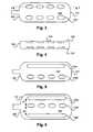
- Appropriate electrodescan be selected from either side of the paddle body 104 to stimulate the desired tissue region.
- the electrodescan stimulate either neural elements deeper than the paddle body, more superficial than the paddle body, or both.
- peripheral nerve stimulationit may be desirable to stimulate a nerve trunk (perhaps to achieve broad paresthesia) located deep near the fascia, or it may be desirable (perhaps to achieve more localized stimulation) to stimulate smaller nerve branches and nerve endings located superficial to the paddle body.
Landscapes
- Health & Medical Sciences (AREA)
- Neurology (AREA)
- Neurosurgery (AREA)
- Orthopedic Medicine & Surgery (AREA)
- Cardiology (AREA)
- Heart & Thoracic Surgery (AREA)
- Engineering & Computer Science (AREA)
- Biomedical Technology (AREA)
- Nuclear Medicine, Radiotherapy & Molecular Imaging (AREA)
- Radiology & Medical Imaging (AREA)
- Life Sciences & Earth Sciences (AREA)
- Animal Behavior & Ethology (AREA)
- General Health & Medical Sciences (AREA)
- Public Health (AREA)
- Veterinary Medicine (AREA)
- Electrotherapy Devices (AREA)
Abstract
Description
Claims (12)
Priority Applications (1)
| Application Number | Priority Date | Filing Date | Title |
|---|---|---|---|
| US11/855,033US9216282B1 (en) | 2007-09-13 | 2007-09-13 | Electrode configurations for electrical stimulation systems and methods of making and using |
Applications Claiming Priority (1)
| Application Number | Priority Date | Filing Date | Title |
|---|---|---|---|
| US11/855,033US9216282B1 (en) | 2007-09-13 | 2007-09-13 | Electrode configurations for electrical stimulation systems and methods of making and using |
Publications (1)
| Publication Number | Publication Date |
|---|---|
| US9216282B1true US9216282B1 (en) | 2015-12-22 |
Family
ID=54847850
Family Applications (1)
| Application Number | Title | Priority Date | Filing Date |
|---|---|---|---|
| US11/855,033Expired - Fee RelatedUS9216282B1 (en) | 2007-09-13 | 2007-09-13 | Electrode configurations for electrical stimulation systems and methods of making and using |
Country Status (1)
| Country | Link |
|---|---|
| US (1) | US9216282B1 (en) |
Cited By (6)
| Publication number | Priority date | Publication date | Assignee | Title |
|---|---|---|---|---|
| WO2020225797A1 (en)* | 2019-05-09 | 2020-11-12 | Salvia Bioelectronics B.V. | An implantable electrical stimulation device with a return electrode |
| WO2020225793A1 (en)* | 2019-05-09 | 2020-11-12 | Salvia Bioelectronics B.V. | An implantable electrical stimulation device with a flexible electrode |
| CN115531724A (en)* | 2022-07-05 | 2022-12-30 | 北京新云医疗科技有限公司 | Electrode lead and spinal cord stimulation system |
| EP4474001A1 (en)* | 2023-06-07 | 2024-12-11 | CereGate GmbH | Apparatus and system for stimulating and / or recording signals travelling along nerve fibers |
| US12357792B2 (en) | 2019-01-04 | 2025-07-15 | Shifamed Holdings, Llc | Internal recharging systems and methods of use |
| US12440656B2 (en) | 2021-04-23 | 2025-10-14 | Shifamed Holdings, Llc | Power management for interatrial shunts and associated systems and methods |
Citations (42)
| Publication number | Priority date | Publication date | Assignee | Title |
|---|---|---|---|---|
| US3718142A (en) | 1971-04-23 | 1973-02-27 | Medtronic Inc | Electrically shielded, gas-permeable implantable electro-medical apparatus |
| US5193539A (en) | 1991-12-18 | 1993-03-16 | Alfred E. Mann Foundation For Scientific Research | Implantable microstimulator |
| US5193540A (en) | 1991-12-18 | 1993-03-16 | Alfred E. Mann Foundation For Scientific Research | Structure and method of manufacture of an implantable microstimulator |
| US5312439A (en) | 1991-12-12 | 1994-05-17 | Loeb Gerald E | Implantable device having an electrolytic storage electrode |
| US5417719A (en) | 1993-08-25 | 1995-05-23 | Medtronic, Inc. | Method of using a spinal cord stimulation lead |
| WO1998037926A1 (en) | 1997-02-26 | 1998-09-03 | Alfred E. Mann Foundation For Scientific Research | Battery-powered patient implantable device |
| WO1998043701A1 (en) | 1997-03-27 | 1998-10-08 | Alfred E. Mann Foundation For Scientific Research | System of implantable devices for monitoring and/or affecting body parameters |
| US5902236A (en)* | 1997-09-03 | 1999-05-11 | Pmt Corporation | Tissue electrode for recording and stimulation |
| US6038484A (en) | 1997-09-02 | 2000-03-14 | Advanced Bionics Corporation | Cochlear electrode with modiolar-hugging system including a flexible positioner |
| US6051017A (en) | 1996-02-20 | 2000-04-18 | Advanced Bionics Corporation | Implantable microstimulator and systems employing the same |
| US6181969B1 (en) | 1998-06-26 | 2001-01-30 | Advanced Bionics Corporation | Programmable current output stimulus stage for implantable device |
| US6185463B1 (en) | 1997-05-01 | 2001-02-06 | Medtronic, Inc. | Implantable short resistant lead |
| WO2001017315A1 (en) | 1999-08-27 | 2001-03-08 | The University Of Melbourne | Electrode array with non-uniform electrode spacing |
| US6343226B1 (en) | 1999-06-25 | 2002-01-29 | Neurokinetic Aps | Multifunction electrode for neural tissue stimulation |
| US20020022873A1 (en)* | 2000-08-10 | 2002-02-21 | Erickson John H. | Stimulation/sensing lead adapted for percutaneous insertion |
| US20020062143A1 (en) | 1999-04-30 | 2002-05-23 | Medtronic, Inc. | Techniques for selective activation of neurons in the brain, spinal cord parenchyma or peripheral nerve |
| US6473653B1 (en)* | 1996-04-04 | 2002-10-29 | Medtronic, Inc. | Selective activation of electrodes within an inplantable lead |
| US6516227B1 (en) | 1999-07-27 | 2003-02-04 | Advanced Bionics Corporation | Rechargeable spinal cord stimulator system |
| US6604283B1 (en) | 1997-09-02 | 2003-08-12 | Advanced Bionics Corporation | Method of making precurved, modiolar-hugging cochlear electrode |
| US6609032B1 (en) | 1999-01-07 | 2003-08-19 | Advanced Bionics Corporation | Fitting process for a neural stimulation system |
| US6609029B1 (en) | 2000-02-04 | 2003-08-19 | Advanced Bionics Corporation | Clip lock mechanism for retaining lead |
| US20040059392A1 (en) | 2002-06-28 | 2004-03-25 | Jordi Parramon | Microstimulator having self-contained power source |
| US6741892B1 (en) | 2000-03-10 | 2004-05-25 | Advanced Bionics Corporation | Movable contact locking mechanism for spinal cord stimulator lead connector |
| US6757970B1 (en) | 2000-11-07 | 2004-07-06 | Advanced Bionics Corporation | Method of making multi-contact electrode array |
| US20040260310A1 (en) | 2002-10-23 | 2004-12-23 | Medtronic, Inc. | Medical lead and method |
| US20050246004A1 (en) | 2004-04-28 | 2005-11-03 | Advanced Neuromodulation Systems, Inc. | Combination lead for electrical stimulation and sensing |
| US6999820B2 (en) | 2003-05-29 | 2006-02-14 | Advanced Neuromodulation Systems, Inc. | Winged electrode body for spinal cord stimulation |
| US7107104B2 (en) | 2003-05-30 | 2006-09-12 | Medtronic, Inc. | Implantable cortical neural lead and method |
| US20060253182A1 (en) | 2004-10-21 | 2006-11-09 | Medtronic, Inc. | Transverse Tripole Neurostimulation Lead, System and Method |
| US20070060991A1 (en) | 2005-04-14 | 2007-03-15 | North Richard B | Electrical stimulation lead, system, and method |
| US20070073356A1 (en)* | 2005-06-09 | 2007-03-29 | Medtronic, Inc. | Combination therapy including peripheral nerve field stimulation |
| US20070150036A1 (en) | 2005-12-27 | 2007-06-28 | Advanced Bionics Corporation | Stimulator leads and methods for lead fabrication |
| US20070150034A1 (en) | 2005-06-09 | 2007-06-28 | Medtronic, Inc. | Implantable medical lead |
| US20070150007A1 (en) | 2005-12-27 | 2007-06-28 | Advanced Bionics Corporation | Non-linear electrode array |
| US20070161294A1 (en) | 2006-01-09 | 2007-07-12 | Advanced Bionics Corporation | Connector and methods of fabrication |
| US20070168007A1 (en) | 2005-01-11 | 2007-07-19 | Advanced Bionics Corporation | Lead Assembly and Method of Making Same |
| US20070179579A1 (en) | 2006-01-26 | 2007-08-02 | Feler Claudio A | Method of neurostimulation of distinct neural structures using single paddle lead to treat multiple pain locations and multi-column, multi-row paddle lead for such neurostimulation |
| WO2007101999A2 (en) | 2006-03-07 | 2007-09-13 | Algotec Limited | Electrostimulation device |
| US20070219595A1 (en) | 2006-03-14 | 2007-09-20 | Advanced Bionics Corporation | Stimulator system with electrode array and the method of making the same |
| US20070239243A1 (en) | 2006-03-30 | 2007-10-11 | Advanced Bionics Corporation | Electrode contact configurations for cuff leads |
| US20070255372A1 (en) | 2006-04-28 | 2007-11-01 | Metzler Michael E | Novel assembly method for spinal cord stimulation lead |
| US20080004674A1 (en)* | 2006-06-30 | 2008-01-03 | Medtronic, Inc. | Selecting electrode combinations for stimulation therapy |
- 2007
- 2007-09-13USUS11/855,033patent/US9216282B1/ennot_activeExpired - Fee Related
Patent Citations (44)
| Publication number | Priority date | Publication date | Assignee | Title |
|---|---|---|---|---|
| US3718142A (en) | 1971-04-23 | 1973-02-27 | Medtronic Inc | Electrically shielded, gas-permeable implantable electro-medical apparatus |
| US5312439A (en) | 1991-12-12 | 1994-05-17 | Loeb Gerald E | Implantable device having an electrolytic storage electrode |
| US5193539A (en) | 1991-12-18 | 1993-03-16 | Alfred E. Mann Foundation For Scientific Research | Implantable microstimulator |
| US5193540A (en) | 1991-12-18 | 1993-03-16 | Alfred E. Mann Foundation For Scientific Research | Structure and method of manufacture of an implantable microstimulator |
| US5417719A (en) | 1993-08-25 | 1995-05-23 | Medtronic, Inc. | Method of using a spinal cord stimulation lead |
| US6051017A (en) | 1996-02-20 | 2000-04-18 | Advanced Bionics Corporation | Implantable microstimulator and systems employing the same |
| US6473653B1 (en)* | 1996-04-04 | 2002-10-29 | Medtronic, Inc. | Selective activation of electrodes within an inplantable lead |
| WO1998037926A1 (en) | 1997-02-26 | 1998-09-03 | Alfred E. Mann Foundation For Scientific Research | Battery-powered patient implantable device |
| WO1998043701A1 (en) | 1997-03-27 | 1998-10-08 | Alfred E. Mann Foundation For Scientific Research | System of implantable devices for monitoring and/or affecting body parameters |
| WO1998043700A1 (en) | 1997-03-27 | 1998-10-08 | Alfred E. Mann Foundation For Scientific Research | System of implantable devices for monitoring and/or affecting body parameters |
| US6185463B1 (en) | 1997-05-01 | 2001-02-06 | Medtronic, Inc. | Implantable short resistant lead |
| US6038484A (en) | 1997-09-02 | 2000-03-14 | Advanced Bionics Corporation | Cochlear electrode with modiolar-hugging system including a flexible positioner |
| US6604283B1 (en) | 1997-09-02 | 2003-08-12 | Advanced Bionics Corporation | Method of making precurved, modiolar-hugging cochlear electrode |
| US5902236A (en)* | 1997-09-03 | 1999-05-11 | Pmt Corporation | Tissue electrode for recording and stimulation |
| US6181969B1 (en) | 1998-06-26 | 2001-01-30 | Advanced Bionics Corporation | Programmable current output stimulus stage for implantable device |
| US6609032B1 (en) | 1999-01-07 | 2003-08-19 | Advanced Bionics Corporation | Fitting process for a neural stimulation system |
| US20020062143A1 (en) | 1999-04-30 | 2002-05-23 | Medtronic, Inc. | Techniques for selective activation of neurons in the brain, spinal cord parenchyma or peripheral nerve |
| US6343226B1 (en) | 1999-06-25 | 2002-01-29 | Neurokinetic Aps | Multifunction electrode for neural tissue stimulation |
| US6516227B1 (en) | 1999-07-27 | 2003-02-04 | Advanced Bionics Corporation | Rechargeable spinal cord stimulator system |
| WO2001017315A1 (en) | 1999-08-27 | 2001-03-08 | The University Of Melbourne | Electrode array with non-uniform electrode spacing |
| US6609029B1 (en) | 2000-02-04 | 2003-08-19 | Advanced Bionics Corporation | Clip lock mechanism for retaining lead |
| US6741892B1 (en) | 2000-03-10 | 2004-05-25 | Advanced Bionics Corporation | Movable contact locking mechanism for spinal cord stimulator lead connector |
| US20020022873A1 (en)* | 2000-08-10 | 2002-02-21 | Erickson John H. | Stimulation/sensing lead adapted for percutaneous insertion |
| US6757970B1 (en) | 2000-11-07 | 2004-07-06 | Advanced Bionics Corporation | Method of making multi-contact electrode array |
| US20040059392A1 (en) | 2002-06-28 | 2004-03-25 | Jordi Parramon | Microstimulator having self-contained power source |
| US20040260310A1 (en) | 2002-10-23 | 2004-12-23 | Medtronic, Inc. | Medical lead and method |
| US6999820B2 (en) | 2003-05-29 | 2006-02-14 | Advanced Neuromodulation Systems, Inc. | Winged electrode body for spinal cord stimulation |
| US7107104B2 (en) | 2003-05-30 | 2006-09-12 | Medtronic, Inc. | Implantable cortical neural lead and method |
| US20050246004A1 (en) | 2004-04-28 | 2005-11-03 | Advanced Neuromodulation Systems, Inc. | Combination lead for electrical stimulation and sensing |
| US20060253182A1 (en) | 2004-10-21 | 2006-11-09 | Medtronic, Inc. | Transverse Tripole Neurostimulation Lead, System and Method |
| US20070168007A1 (en) | 2005-01-11 | 2007-07-19 | Advanced Bionics Corporation | Lead Assembly and Method of Making Same |
| US20070060991A1 (en) | 2005-04-14 | 2007-03-15 | North Richard B | Electrical stimulation lead, system, and method |
| US20070150034A1 (en) | 2005-06-09 | 2007-06-28 | Medtronic, Inc. | Implantable medical lead |
| US20070073356A1 (en)* | 2005-06-09 | 2007-03-29 | Medtronic, Inc. | Combination therapy including peripheral nerve field stimulation |
| US20070150036A1 (en) | 2005-12-27 | 2007-06-28 | Advanced Bionics Corporation | Stimulator leads and methods for lead fabrication |
| US20070150007A1 (en) | 2005-12-27 | 2007-06-28 | Advanced Bionics Corporation | Non-linear electrode array |
| US20070161294A1 (en) | 2006-01-09 | 2007-07-12 | Advanced Bionics Corporation | Connector and methods of fabrication |
| US20070179579A1 (en) | 2006-01-26 | 2007-08-02 | Feler Claudio A | Method of neurostimulation of distinct neural structures using single paddle lead to treat multiple pain locations and multi-column, multi-row paddle lead for such neurostimulation |
| WO2007101999A2 (en) | 2006-03-07 | 2007-09-13 | Algotec Limited | Electrostimulation device |
| US20070219595A1 (en) | 2006-03-14 | 2007-09-20 | Advanced Bionics Corporation | Stimulator system with electrode array and the method of making the same |
| US20070239243A1 (en) | 2006-03-30 | 2007-10-11 | Advanced Bionics Corporation | Electrode contact configurations for cuff leads |
| US20070255372A1 (en) | 2006-04-28 | 2007-11-01 | Metzler Michael E | Novel assembly method for spinal cord stimulation lead |
| US20080004674A1 (en)* | 2006-06-30 | 2008-01-03 | Medtronic, Inc. | Selecting electrode combinations for stimulation therapy |
| US20080004675A1 (en) | 2006-06-30 | 2008-01-03 | Medtronic, Inc. | Selecting electrode combinations for stimulation therapy |
Non-Patent Citations (6)
| Title |
|---|
| U.S. Appl. No. 11/238,240, filed Sep. 29, 2005 (19 pages). |
| U.S. Appl. No. 11/319,291, filed Dec. 27, 2005. |
| U.S. Appl. No. 11/327,880, filed Jan. 9, 2006. |
| U.S. Appl. No. 11/369,309, filed Mar. 6, 2006. |
| U.S. Appl. No. 11/375,638, filed Mar. 14, 2006. |
| U.S. Appl. No. 11/393,991, filed Mar. 30, 2006. |
Cited By (9)
| Publication number | Priority date | Publication date | Assignee | Title |
|---|---|---|---|---|
| US12357792B2 (en) | 2019-01-04 | 2025-07-15 | Shifamed Holdings, Llc | Internal recharging systems and methods of use |
| WO2020225797A1 (en)* | 2019-05-09 | 2020-11-12 | Salvia Bioelectronics B.V. | An implantable electrical stimulation device with a return electrode |
| WO2020225793A1 (en)* | 2019-05-09 | 2020-11-12 | Salvia Bioelectronics B.V. | An implantable electrical stimulation device with a flexible electrode |
| US12109408B2 (en) | 2019-05-09 | 2024-10-08 | Salvia Bioelectronic B.V. | Implantable electrical stimulation device with a flexible electrode |
| US12440656B2 (en) | 2021-04-23 | 2025-10-14 | Shifamed Holdings, Llc | Power management for interatrial shunts and associated systems and methods |
| CN115531724A (en)* | 2022-07-05 | 2022-12-30 | 北京新云医疗科技有限公司 | Electrode lead and spinal cord stimulation system |
| CN115531724B (en)* | 2022-07-05 | 2024-05-24 | 北京新云医疗科技有限公司 | Electrode lead and spinal cord stimulation system |
| EP4474001A1 (en)* | 2023-06-07 | 2024-12-11 | CereGate GmbH | Apparatus and system for stimulating and / or recording signals travelling along nerve fibers |
| WO2024251518A1 (en)* | 2023-06-07 | 2024-12-12 | CereGate GmbH | Apparatus and system for stimulating and / or recording signals travelling along nerve fibers |
Similar Documents
| Publication | Publication Date | Title |
|---|---|---|
| US7803021B1 (en) | Implantable electrical stimulation systems with leaf spring connective contacts and methods of making and using | |
| US9956394B2 (en) | Connectors for electrical stimulation systems and methods of making and using | |
| AU2014302793B2 (en) | Paddle leads and lead arrangements for dorsal horn stimulation and systems using the leads | |
| US8359107B2 (en) | Electrode design for leads of implantable electric stimulation systems and methods of making and using | |
| US8983608B2 (en) | Lead connector for an implantable electric stimulation system and methods of making and using | |
| US9409032B2 (en) | Systems and methods for making and using connector assembly retainers for electrical stimulation systems | |
| US8374695B2 (en) | Lead splitter for an electrical stimulation system and systems and methods for making and using | |
| US8406883B1 (en) | Lead assembly for electrical stimulation systems and methods of making and using | |
| US8332049B2 (en) | Implantable multi-lead electric stimulation system and methods of making and using | |
| US20110009933A1 (en) | Piggy-back percutaneous lead insertion kit | |
| US9878148B2 (en) | Lead with contact end conductor guide and methods of making and using | |
| US8655457B2 (en) | Paddle lead configurations for electrical stimulation systems and methods of making and using | |
| US10232169B2 (en) | Burr hole plugs for electrical stimulation systems and methods of making and using | |
| US9101755B2 (en) | Systems and methods for making and using contact assemblies for leads of electrical stimulation systems | |
| US9216282B1 (en) | Electrode configurations for electrical stimulation systems and methods of making and using | |
| US8965528B2 (en) | Systems and methods for making and using electrical stimulation leads with shaped mesh contact assemblies | |
| US20130282091A1 (en) | Systems and methods for making and using improved electrodes for implantable paddle leads | |
| US8249721B2 (en) | Method for fabricating a neurostimulation lead contact array |
Legal Events
| Date | Code | Title | Description |
|---|---|---|---|
| AS | Assignment | Owner name:BOSTON SCIENTIFIC NEUROMODULATION CORPORATION, CALIFORNIA Free format text:CHANGE OF NAME;ASSIGNOR:ADVANCED BIONICS CORPORATION;REEL/FRAME:020296/0477 Effective date:20071116 Owner name:BOSTON SCIENTIFIC NEUROMODULATION CORPORATION, CAL Free format text:CHANGE OF NAME;ASSIGNOR:ADVANCED BIONICS CORPORATION;REEL/FRAME:020296/0477 Effective date:20071116 | |
| FEPP | Fee payment procedure | Free format text:PAYOR NUMBER ASSIGNED (ORIGINAL EVENT CODE: ASPN); ENTITY STATUS OF PATENT OWNER: LARGE ENTITY | |
| AS | Assignment | Owner name:BOSTON SCIENTIFIC NEUROMODULATION CORPORATION, CAL Free format text:ASSIGNMENT OF ASSIGNORS INTEREST;ASSIGNORS:MOFFITT, MICHAEL ADAM;CARBUNARU, RAFAEL;SIGNING DATES FROM 20151103 TO 20151104;REEL/FRAME:036996/0984 | |
| STCF | Information on status: patent grant | Free format text:PATENTED CASE | |
| FEPP | Fee payment procedure | Free format text:MAINTENANCE FEE REMINDER MAILED (ORIGINAL EVENT CODE: REM.); ENTITY STATUS OF PATENT OWNER: LARGE ENTITY | |
| LAPS | Lapse for failure to pay maintenance fees | Free format text:PATENT EXPIRED FOR FAILURE TO PAY MAINTENANCE FEES (ORIGINAL EVENT CODE: EXP.); ENTITY STATUS OF PATENT OWNER: LARGE ENTITY | |
| STCH | Information on status: patent discontinuation | Free format text:PATENT EXPIRED DUE TO NONPAYMENT OF MAINTENANCE FEES UNDER 37 CFR 1.362 | |
| FP | Lapsed due to failure to pay maintenance fee | Effective date:20191222 |