US9216244B2 - Inline swivel connection for multi-lumen tubing - Google Patents
Inline swivel connection for multi-lumen tubingDownload PDFInfo
- Publication number
- US9216244B2 US9216244B2US13/181,361US201113181361AUS9216244B2US 9216244 B2US9216244 B2US 9216244B2US 201113181361 AUS201113181361 AUS 201113181361AUS 9216244 B2US9216244 B2US 9216244B2
- Authority
- US
- United States
- Prior art keywords
- conduit
- collar
- lumen
- adapter
- bulkhead
- Prior art date
- Legal status (The legal status is an assumption and is not a legal conclusion. Google has not performed a legal analysis and makes no representation as to the accuracy of the status listed.)
- Expired - Fee Related, expires
Links
Images


Classifications
- A61M1/0088—
- A—HUMAN NECESSITIES
- A61—MEDICAL OR VETERINARY SCIENCE; HYGIENE
- A61M—DEVICES FOR INTRODUCING MEDIA INTO, OR ONTO, THE BODY; DEVICES FOR TRANSDUCING BODY MEDIA OR FOR TAKING MEDIA FROM THE BODY; DEVICES FOR PRODUCING OR ENDING SLEEP OR STUPOR
- A61M39/00—Tubes, tube connectors, tube couplings, valves, access sites or the like, specially adapted for medical use
- A61M39/10—Tube connectors; Tube couplings
- A61M39/105—Multi-channel connectors or couplings, e.g. for connecting multi-lumen tubes
- A—HUMAN NECESSITIES
- A61—MEDICAL OR VETERINARY SCIENCE; HYGIENE
- A61M—DEVICES FOR INTRODUCING MEDIA INTO, OR ONTO, THE BODY; DEVICES FOR TRANSDUCING BODY MEDIA OR FOR TAKING MEDIA FROM THE BODY; DEVICES FOR PRODUCING OR ENDING SLEEP OR STUPOR
- A61M1/00—Suction or pumping devices for medical purposes; Devices for carrying-off, for treatment of, or for carrying-over, body-liquids; Drainage systems
- A61M1/84—Drainage tubes; Aspiration tips
- A61M1/86—Connectors between drainage tube and handpiece, e.g. drainage tubes detachable from handpiece
- A—HUMAN NECESSITIES
- A61—MEDICAL OR VETERINARY SCIENCE; HYGIENE
- A61M—DEVICES FOR INTRODUCING MEDIA INTO, OR ONTO, THE BODY; DEVICES FOR TRANSDUCING BODY MEDIA OR FOR TAKING MEDIA FROM THE BODY; DEVICES FOR PRODUCING OR ENDING SLEEP OR STUPOR
- A61M1/00—Suction or pumping devices for medical purposes; Devices for carrying-off, for treatment of, or for carrying-over, body-liquids; Drainage systems
- A61M1/90—Negative pressure wound therapy devices, i.e. devices for applying suction to a wound to promote healing, e.g. including a vacuum dressing
- A61M1/91—Suction aspects of the dressing
- A61M1/912—Connectors between dressing and drainage tube
- A—HUMAN NECESSITIES
- A61—MEDICAL OR VETERINARY SCIENCE; HYGIENE
- A61M—DEVICES FOR INTRODUCING MEDIA INTO, OR ONTO, THE BODY; DEVICES FOR TRANSDUCING BODY MEDIA OR FOR TAKING MEDIA FROM THE BODY; DEVICES FOR PRODUCING OR ENDING SLEEP OR STUPOR
- A61M39/00—Tubes, tube connectors, tube couplings, valves, access sites or the like, specially adapted for medical use
- A61M39/10—Tube connectors; Tube couplings
- A61M39/1055—Rotating or swivel joints
- A—HUMAN NECESSITIES
- A61—MEDICAL OR VETERINARY SCIENCE; HYGIENE
- A61M—DEVICES FOR INTRODUCING MEDIA INTO, OR ONTO, THE BODY; DEVICES FOR TRANSDUCING BODY MEDIA OR FOR TAKING MEDIA FROM THE BODY; DEVICES FOR PRODUCING OR ENDING SLEEP OR STUPOR
- A61M39/00—Tubes, tube connectors, tube couplings, valves, access sites or the like, specially adapted for medical use
- A61M39/10—Tube connectors; Tube couplings
- A61M2039/1077—Adapters, e.g. couplings adapting a connector to one or several other connectors
- Y—GENERAL TAGGING OF NEW TECHNOLOGICAL DEVELOPMENTS; GENERAL TAGGING OF CROSS-SECTIONAL TECHNOLOGIES SPANNING OVER SEVERAL SECTIONS OF THE IPC; TECHNICAL SUBJECTS COVERED BY FORMER USPC CROSS-REFERENCE ART COLLECTIONS [XRACs] AND DIGESTS
- Y10—TECHNICAL SUBJECTS COVERED BY FORMER USPC
- Y10S—TECHNICAL SUBJECTS COVERED BY FORMER USPC CROSS-REFERENCE ART COLLECTIONS [XRACs] AND DIGESTS
- Y10S285/00—Pipe joints or couplings
- Y10S285/904—Cryogenic
- Y—GENERAL TAGGING OF NEW TECHNOLOGICAL DEVELOPMENTS; GENERAL TAGGING OF CROSS-SECTIONAL TECHNOLOGIES SPANNING OVER SEVERAL SECTIONS OF THE IPC; TECHNICAL SUBJECTS COVERED BY FORMER USPC CROSS-REFERENCE ART COLLECTIONS [XRACs] AND DIGESTS
- Y10—TECHNICAL SUBJECTS COVERED BY FORMER USPC
- Y10T—TECHNICAL SUBJECTS COVERED BY FORMER US CLASSIFICATION
- Y10T137/00—Fluid handling
- Y10T137/8593—Systems
- Y10T137/85978—With pump
Definitions
- the inventionrelates generally to methods and devices for conducting fluids and gases within a reduced pressure treatment system.
- the inventionrelates more specifically to an inline connector for multi-lumen tubing that allows free rotation of one end of the tubing with respect to the other end of the tubing.
- Wound closureis one application of tissue growth and healing.
- Wound closuregenerally involves the inward migration of epithelial and subcutaneous tissue adjacent the wound. This migration is ordinarily assisted by the inflammatory process, whereby blood flow is increased and various functional cell types are activated. As a result of the inflammatory process, blood flow through damaged or broken vessels is stopped by capillary level occlusion, whereafter cleanup and rebuilding operations may begin.
- this processis hampered when a wound is large or has become infected. In such wounds, a zone of stasis (i.e. an area in which localized swelling of tissue restricts the flow of blood to the tissues) forms near the surface of the wound.
- the epithelial and subcutaneous tissues surrounding the woundnot only receive diminished oxygen and nutrients, but are also less able to successfully fight bacterial infection and, thus, less able to naturally close the wound and heal the tissue. Additionally, some wounds harden and inflame to such a degree that closure by stapling or suturing is not feasible. Examples of wounds not readily treatable with staples or suturing include large, deep, open wounds; decubitus ulcers; ulcers resulting from chronic osteomyelitis; and partial thickness burns that subsequently develop into full thickness burns.
- One important component of a reduced pressure treatment systemis the conduit system that connects the reduced pressure source (a vacuum pump, typically) to the tissue contact components (a granular foam layer or other manifolding device, typically) enclosed within a pad or wound dressing.
- This reduced pressure conduit structuremay include a more complex multi-lumen structure in order to provide ancillary conduits for monitoring and alternative treatment regimens.
- the ability to maintain a clear, consistent, and leak-free connectionis important within an effective reduced pressure treatment system.
- Various effortshave been made in the past to provide suitable conduit configurations to effectively connect the reduced pressure source to the tissue treatment site at the wound bed.
- a variety of systems and devicesare utilized in the veterinary medicine environment to connect animal subjects to medical instrumentation. In both research and treatment situations it is often necessary to connect electrical wires and tubular conduit lines between stationary instrumentation and the subject animal that is typically moving about an enclosure when not sedated.
- reduced pressure tissue treatment regimenswith animal subjects, both for research purposes (i.e. to develop systems intended for human use) and for veterinary systems intended for animal treatment, has become more frequent.
- Such reduced pressure tissue treatment systemsare implemented on a variety of animals, large and small, from mice and rats to rabbits and sheep.
- Inherent in reduced pressure tissue treatment systemsis the use of a number of tubular conduit lines connecting the tissue site on the subject animal to stationary instrumentation typically in the form of negative pressure sources and the associated fluid containers.
- tissue site on the subject animalWith human patients, it is often possible (although certainly not always possible) to insist upon reduced mobility or even immobile conditions in order to carry out the tissue treatment. With animal patients, this is of course generally not possible at all unless the animal is sedated.
- As the preferenceis to permit the tissue to heal over a period of time, it is generally not practical to maintain sedation of an animal to carry out either research or treatment with reduced pressure application.
- the problems that arise therefore in maintaining an effective connection between the negative pressure instrumentation and the reduced pressure treatment dressingcan become complex.
- a direct connection between the instrumentation and the wound dressingcan quickly become disabled with the movement of the subject animal even within a relatively small enclosure.
- the movementincludes not just side to side motion, but rotational motion often in the form of walking circles around the enclosure.
- a direct link therefore with tubing between the instrumentation and the wound sitecould never be maintained without some rotationally moveable connection.
- Ancillary to this larger primary lumenare typically one or more (often four radially spaced) smaller lumens that serve to provide a clear path between the reduced pressure treatment instrumentation and the wound site for the purpose of measuring pressure or carrying out other similar therapeutic functions. It is important for these ancillary lumens to remain clear in order for accurate pressure measurements to be made and the treatment regimen to be carried out accurately. Many efforts have been made to isolate the primary lumen from the ancillary lumens in order to prevent the clogging or contamination of the smaller ancillary lumens with fluids and solids being withdrawn from the wound bed.
- an apparatus for connecting multi-lumen conduitscomprises a conduit adapter and a conduit collar.
- the conduit adaptermay include a housing, a bayonet connector, and a support member connecting the housing and the bayonet connector.
- the bayonet connectorgenerally has a single bore extending lengthwise through the connector, and optionally a conduit stop that limits the extent to which the connector may be inserted into a conduit.
- the support memberincludes at least one aperture that permits fluid or gas communication through the support member.
- the conduit collarhas a first end and a second end. The first end is sized for insertion into the housing, and the second end is adapted to receive a first multi-lumen conduit.
- the housingis adapted to receive the first end of the conduit collar such that the bayonet connector engages a primary lumen of the first multi-lumen conduit and the primary lumen of the first multi-lumen conduit fluidly communicates with the bore.
- the housingalso is adapted to receive a second multi-lumen conduit such that the bayonet connector engages a primary lumen of the second multi-lumen conduit, and the primary lumen of the second multi-lumen conduit fluidly communicates with the bore and the primary lumen of the first multi-lumen conduit.
- the conduit adapter and the conduit collarare capable of 360 degree rotation relative to each other about an axis shared by the conduit adapter and the conduit collar, while permitting fluid communication between ancillary lumens of the first multi-lumen conduit and the second multi-lumen conduit through the aperture in the support member.
- a swivel connector assemblyfor connecting multi-lumen conduits.
- the assemblycomprises a connection collar having a first threaded section, a first bulkhead positioned within the connection collar, a conduit adapter, a bearing collar having a second threaded section, a spacer collar, a mounting plate, a shaft, a bearing assembly, and a conduit collar.
- the conduit adaptercomprises a housing, a bayonet connector having a single bore and a conduit stop, a support member connecting the housing and the bayonet connector, and an aperture through the support member.
- the spacer collaris positioned between the connection collar and the bearing collar, and the mounting plate between the bearing collar and the connection collar.
- One end of the bearing assemblyis coupled to the shaft.
- the threaded section of the bearing collaris engaged with the threaded section of the connection collar.
- a first end of the conduit collaris positioned within the adapter and the second end of the conduit collar is positioned within the shaft.
- FIG. 1is a schematic, exploded side view having a portion shown with hidden lines of a swivel connector assembly according to an embodiment of the present invention including a conduit connector for receiving two multi-lumen conduits;
- FIG. 2Ais a schematic, cross-sectional view of a conduit adapter of the swivel connector assembly of FIG. 1 ;
- FIG. 2Bis a schematic, end view of the conduit adapter shown in FIG. 1 ;
- FIG. 3Ais a schematic, longitudinal, exploded cross-sectional view of a conduit collar
- FIG. 3Bis a schematic, cross-sectional side view of the conduit collar of FIGS. 1 and 3A and a second multi-lumen conduit inserted into the conduit adapter of FIGS. 1 and 2A and having a first multi-lumen conduit inserted;
- FIG. 4is a schematic, side view of the assembled swivel connector assembly of FIG. 1 positioned on a bracket assembly with the multi-lumen conduits shown in cross section;
- FIG. 5is a schematic, exploded side view, with portion shown in broken lines, of a swivel connector assembly according to an embodiment of the present invention, the swivel connector assembly is shown with multi-lumen conduits in cross section;
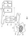
- FIG. 6is a schematic side view, with a portion shown in perspective view, of a reduced pressure treatment system incorporating a swivel connector and bracket assembly according to an embodiment of the present invention
- FIG. 7is a schematic side view, with a portion shown in perspective view, of a reduced pressure treatment system incorporating a swivel connector and a rotating adapter at a dressing according to an embodiment of the present invention
- FIG. 8is an exploded perspective view of the rotating adapter of FIG. 7 ;
- FIG. 9is an assembled cross-sectional side view of the rotating adapter of FIG. 8 .
- a rotating swivel connectoris used in conjunction with multi-lumen conduit, such as the type often used in reduced pressure treatment systems.
- the connector assemblycomprises a conduit adapter and a conduit collar that mate two sections of tubing together in a manner that allows for relatively free rotation.
- Surrounding the conduit adapter and the conduit collarare larger, threaded enclosure components that control the relative, axial positioning of the conduit adapter and the conduit collar, which serves to maintain a connection and vary the level of force required to rotate the connection.
- a group of “stationary components”position and hold a conduit that typically extends from the instrumentation used in a reduced pressure treatment system.
- a second group of componentsinclude a rotational bearing assembly that is attached to a rotating shaft that grips and positions the conduit collar, which is attached to a conduit connected to a subject animal or human patient (at the tissue site).
- the assemblymay be modified to accommodate significant variations in the size of the subject animal or the human patient.
- the basic componentsallow the user to vary the tightness of the connection, and therefore the ease with which the connection swivels or rotates, by rotating one threaded enclosure component into or out from a second threaded enclosure component, thereby varying the amount of rotational friction between the conduit adapter and the conduit collar.
- a swivel connector assembly 5includes stationary components 10 and rotational components 12 .
- a section of multi-lumen conduit 14is connected between the swivel connector assembly 5 and the reduced pressure treatment system instrumentation (as shown in FIGS. 6 and 7 ).
- a second conduit 16extends from the swivel connector assembly 5 to a subject animal or patient, or more specifically, to a dressing positioned on the subject.
- an axial line indicated in dashed and dotted format in FIG. 1represents the axis of assembly and symmetry around which these generally cylindrical components are placed and connected.
- the stationary components 10may include a bulkhead 18 , which receives the conduit 14 through a central passage 19 .
- the bulkhead 18is positioned within and is rigidly connected to a connection collar 20 , which is generally stationary with respect to the reduced pressure treatment system instrumentation and which forms a first half of two threaded enclosure components.
- the connection collar 20may be a PVC component of the type typically used to connect a PVC pipe section to a female (threaded) iron pipe (FIP) section.
- the connection collar 20includes a threaded section that allows adjustability of the swivel connector. The threaded section is preferably internal to the connection collar 20 .
- the stationary components 10may further include a conduit adapter 22 , which is attached to conduit 14 only after conduit 14 has passed through the central passage 19 of the bulkhead 18 .
- the conduit 14typically is press-fit into the conduit adapter 22 .
- a set screw 23 or other fastenermay secure the conduit adapter 22 within the central passage 19 of the bulkhead 18 .
- a plurality of set screws(3 or 4 in certain embodiments) may secure the bulkhead 18 within the connection collar 20 , one of which is seen in the orientation of FIG. 1 .
- either the central passage 19 or the conduit adapter 22may be tapered so that conduit adapter 22 is rigidly fixed in the bulkhead 18 when pressed into position.
- the bearing collar 26is constructed in the manner of a PVC adapter of the type that connects a PVC pipe to a male (threaded) iron pipe (MIP) fitting.
- a spacer collar 24may be positioned around the threads of bearing collar 26 in order to control the tightness of the connection and the seal between the internal conduit adapter 22 and a conduit collar 30 .
- a snap ring 28which may be compressed inward and then released to fit within a slot 29 positioned in the bearing collar 26 once the rotational components 12 (described in detail below) have been installed therein.
- the mounting plate 36may include a plurality of peripheral bolt holes to attach the plate, and thus the swivel connector assembly 5 , to a bracket or the like associated with an animal enclosure. Typically, the mounting of the swivel connector assembly 5 would be in a position above an animal on the top of an enclosure or on a bracket extending from the top edge of a wall of the enclosure.
- the conduit adapter 22is secured within the combination of the stationary components 10 and attached to the conduit 14 through the bulkhead 18 .
- the geometry of the conduit adapter 22 and the conduit collar 30are coaxially aligned within the enclosure components when the enclosure components are fixed in place, as described.
- the tightness with which the conduit adapter 22 and the conduit collar 30 are matedis controlled in part by the degree to which the bearing collar 26 is threaded into the connection collar 20 .
- the connection collar 20 , the bearing collar 26 , and the spacer collar 24are preferably constructed of PVC material.
- the bulkhead 18is preferably constructed from a cylindrical block of polyoxymethylene plastic sold under the trademark DELRIN.
- the rotational components 12may include the conduit collar 30 , a first shaft member 32 , and a portion of a bearing assembly 34 .
- the bearing assembly 34may include one or more bearing sets 35 (two shown in FIG. 1 ).
- Each bearing set 35generally includes an inner race (not shown) and an outer race 39 , separated by ball bearings, roller bearings, or other beatings.
- the inner race of each bearing set 35is positioned on a second shaft member 37 , which includes a flanged end 38 .
- the multi-lumen conduit 16passes through the second shaft member 37 and the first shaft member 32 to a point where it press-fits into the conduit collar 30 .
- This combination of the multi-lumen conduit 16 and the conduit collar 30is positioned within a central bore 33 of the first shaft member 32 , and may be fixed there with a set screw 23 or other fastener through a drilled aperture in shaft 32 , as shown.
- the first shaft member 32is positioned onto the second shaft member 37 , and likewise may be rigidly fixed thereto with a set screw 23 or other fastener through the drilled aperture in shaft 32 .
- the second shaft member 37may be extended and manufactured to include the central bore 33 , such that a separate first shaft member 32 is not necessary.
- the first shaft member 32 and the second shaft 37 memberare manufactured as separate components, the first shaft member 32 is preferably constructed from a cylindrical block of polyoxymethylene plastic sold under the trademark DELRIN, and is generally of sufficient length to extend through the bearing collar 26 so that conduit collar 30 may be inserted into conduit adapter 22 when the components are assembled.
- DELRINpolyoxymethylene plastic sold under the trademark DELRIN
- the bearing assembly 34provides a heavy duty, rotatable assembly that receives the multi-lumen conduit 16 .
- the axial alignment and assembly of the entire set of componentsis generally indicated by the axial line shown in FIG. 1 .
- the snap ring 28is withdrawn from this linear arrangement of components until such time as the assembly of rotating components 12 is inserted into the stationary components 10 , whereafter the snap ring 28 is put into place and serves to hold the entire assembly of rotating components 12 , and in particular the bearing assembly 34 , within the enclosure established by the stationary components 10 .
- a flexible metal sheath(not shown), such as of a BX Cable type, may encapsulate the conduit 16 and be attached to the flanged end 38 of the shaft 37 .
- the flexible sheathextends from the swivel connector to a dressing (or harness) positioned on a subject animal or patient.
- a sheathrotates with the conduit 16 and the rotational components 12 .
- the sheathprotects the conduit 16 from being damaged by chewing or other activity by the animal or patient, and also transmits rotational force from the dressing to the swivel connector 5 .
- the conduit adapter 22 and the conduit collar 30mate together loosely in a manner described in more detail below, but are held in position against each other by the structural geometry of the components and the enclosure shown.
- the degree of insertion of the conduit collar 30 into the conduit adapter 22determines the tightness of the seal between the conduit 14 and the conduit 16 .
- An o-ring 42 within the conduit adapter 22mates with an end surface 45 of the conduit collar 30 when the conduit collar 30 is inserted within the conduit adapter 22 .
- the amount of force exerted by the conduit collar 30 on the o-ring 42determines the ease with which the conduit collar 30 rotates within the conduit adapter 22 . This force may be increased by tightening the threaded connection between the bearing collar 26 and the connection collar 20 . Similarly, the force applied by the conduit collar 30 to the o-ring 42 may be decreased by loosening the threaded connection between the bearing collar 26 and the connection collar 20 .
- the bearing assembly 34permits the rotational components 12 to rotate freely but for the frictional contact between the o-ring 42 and the conduit collar 30 .
- Turning the bearing collar 26 with respect to the connection collar 20 to tighten the swivel connector assembly 5increases the friction between the o-ring 42 and the conduit collar 30 , and thereby reduces the ease with which the swivel connector assembly 5 turns.
- turning the bearing collar 26 to loosen the swivel connector assemblyincreases the ease with which the swivel connector assembly 5 turns.
- the conduit collar 30While it is desired that the rotational components 12 rotate easily within the stationary components 10 , the conduit collar 30 must engage the o-ring 42 with enough force to maintain a seal between the conduit collar 30 and the conduit adapter 22 .
- a lubricantis preferably applied to the o-ring 42 .
- the conduit adapter 22includes a bayonet connector 40 having a bore 48 , a housing 41 , and a support member 43 .
- the support member 43provides a generally rigid connection between the housing 41 and the bayonet connector 40 .
- One or more apertures 44penetrate the support member 43 .
- the support member 43has a width that is thin relative to the length of the bayonet connector 40 and the housing 41 .
- the support member 43may have any configuration that maintains the position of the bayonet connector relative to the housing 41 while permitting fluid communication through the support member 43 .
- the bayonet connector 40penetrates and engages the primary lumens of the conduit 14 and the conduit 16 .
- a conduit stop 46limits the penetration of the bayonet connector 40 into the conduit 14 so as to maintain a cavity between the conduit 14 and the aperture 44 .
- the conduit stop 46also may limit the penetration of the bayonet connector 40 into the conduit 16 .
- the bayonet connector 40may be tapered to limit the penetration into the conduit 14 and the conduit 16 .
- the bayonet connector 40 , the housing 41 , and the support member 43may be manufactured as a single integrated component, or as separate components that are subsequently assembled.
- the o-ring 42is positioned to provide an appropriate seal to isolate the ancillary lumens of the conduit 16 from the external environment when the conduit adapter 22 and the conduit collar 30 are assembled.
- a second o-ring(not shown) may optionally be positioned in the interior of the conduit adapter 22 on the side of the support member 43 opposite the o-ring 42 to further seal the ancillary lumens of the conduit 14 from the external environment.
- FIG. 2Billustrates one embodiment of the peripheral apertures 44 in the conduit adapter 22 that permit fluid communication between the ancillary lumens of the multi-lumen conduits 14 and 16 .
- FIG. 3AA cross-section of the conduit collar 30 is shown in FIG. 3A , aligned with the multi-lumen conduit 16 .
- An external surface 50 of the conduit collar 30is sufficiently smooth to allow the conduit collar 30 to rotate within the conduit adapter 22 .
- the internal bore 52 of the conduit collar 30is sized to accommodate the press-fit insertion of the conduit 16 , which generally includes a primary lumen 59 b and ancillary lumens 56 a and 56 b .
- a conduit stop 53limits the penetration of the conduit 16 into the conduit collar 30 , leaving a gap between opening 55 and the end of the conduit 16 . It should be noted that some variation in the depth with which the conduit collar 30 may be inserted into the conduit adapter 22 allows for similar variations in the tightness of the overall swivel connection.
- FIG. 3Bis a cross-section of an assembly comprising the conduit 14 , the conduit adapter 22 , the conduit collar 30 , and the conduit 16 .
- the conduit 14is pressed into position in the conduit adapter 22 so that the primary lumen 59 a engages the bayonet connector 40 .
- the conduit 16is pressed into the conduit collar 30 , which is pressed into the end of the conduit adapter 22 so that the primary lumen 59 b engages the bayonet connector 40 on the end opposite the conduit 14 .
- the conduit stop 46(or the taper of bayonet connector 40 ) prevents the conduit 14 from contacting the support member 43 .
- the conduit collar 30prevents the conduit 16 from contacting the support member 44 , leaving a cavity between the ancillary lumens 56 a and 56 b and the apertures 44 .
- the cavity on each side of the apertures 44permits fluid communication between the ancillary lumens via the apertures 44 , regardless of the relative orientation of the conduits 14 and 16 .
- FIG. 4provides an example of the manner in which a swivel connector assembly may be mounted over or on top of an enclosure or the like.
- a bracket frame 60receives and retains a mounting bracket 36 as shown.
- the frame 60provides a variety of mounting apertures to position and secure the frame and the swivel connector to some part of the enclosure 62 .
- FIG. 5for a brief description of an alternate embodiment of the invention, sized and dimensioned to be suitable for use in conjunction with smaller animal subjects.
- the basic principles of the previously described embodimentare retained in the assembly 70 shown in FIG. 5 with commensurate reductions in size and weight to a number of the components.
- the conduit adapter 22 and the conduit collar 30 of the connector assemblyare the same as in the previous description, as are the conduits 14 and 16 .
- Wire wound conduit shield 82is provided in this embodiment to cover the length of the conduit 16 that extends from the swivel connector to the subject animal.
- the rotating components of the embodiment showncomprise the conduit 16 , the conduit shield 82 , the conduit collar 30 , the shaft 74 , and the bearing assembly 76 .
- the shaft 74retains the conduit shield 82 by way of a set screw 23 or other fastener, and thereby retains the conduit collar 30 attached to the conduit 16 .
- the shaft 74 and the bearing assembly 76may be a unitary component or separate components.
- the bearing assembly 76is secured (by way of the stationary exterior portion of the bearing) within the bearing collar 78 .
- the stationary components of this alternative embodimentinclude the bearing collar 78 , the bulkhead 72 , the conduit adapter 22 , and the conduit 14 .
- the conduit adapter 22is press-fit onto the conduit 14 after the conduit 14 has passed through a central bore in the bulkhead 72 .
- These two componentsare then secured within bulkhead 72 by way of a set screw 23 or other fastener, as shown.
- a mounting bracket 80is independently attached to the bearing collar 78 , rather than included in the threaded assembly described above. This may be accomplished by either attaching the bracket 80 to the bearing collar 78 by way of screws or bolts or by clamping the bearing collar 78 within a mounting frame (not shown) that is itself attached to the mounting bracket 80 .
- the bracket 80has a central aperture to permit the passage of the combination of the conduit shield 82 and the conduit 16 .
- FIG. 5Operation of the embodiment shown in FIG. 5 is similar to that described above.
- the components shownserve to position the conduit adapter 22 and the conduit collar 30 such that upon assembly of the swivel connector they align and engage to complete the conduit connection.
- the use of the described embodimentonly in conjunction with a smaller sized animal subject reduces the need for variation in the tightness of the seal and therefore of the rotational freedom of the swivel. Some variation may be achieved by varying the specific placement of the set screws involved in the assembly of the device, but is not generally required in practice.
- the swivelmay be mounted to an enclosure (not shown) or the like, preferably in a vertical orientation with the combination of the conduit shield 82 and the conduit 16 being directed to an animal subject from above.
- FIG. 6illustrates a swivel connector in conjunction with a reduced pressure treatment system.
- the swivel connector 64is positioned within a bracket frame 60 , which is in turn secured to an elevated support structure 62 as described above.
- the conduit 14connects to the reduced pressure treatment system instrumentation 90 , which comprises an effluent collection container 94 , a reduced pressure pump 96 , and monitoring instrumentation 98 .
- These instrumentation componentsare connected to the conduit 14 by way of a manifold connector 92 in a manner known in the art.
- the combination of the reduced pressure treatment instrumentation 90 and the swivel connector assemblycomprise the stationary components of the overall reduced pressure treatment system.
- the movable components of the reduced pressure treatment systembegin at the swivel connector 64 and extend towards an animal subject or human patient by way of the conduit 16 .
- the conduit 16connects to the tissue treatment site, typically through a dressing 100 as shown.
- the dressing 100comprises a granulated foam material 102 positioned within the tissue, with an adapter 104 positioned in a centralized location on the foam material 102 .
- An adhesive drape 106is typically placed over the foam 102 , but allows for passage through to the adapter 104 .
- the conduit 16connects the dressing 100 to the swivel connector 64 in a manner that permits the generally free movement (rotation) of the conduit 16 below the swivel connector.
- the dressing 100In the case of animal subjects it may be necessary to position the dressing 100 within a harness that immobilizes the conduit 16 on the animal subject and transfers the required motion up to the swivel connector 64 . Similar, although typically less substantial, patient conduit immobilizing measures may be taken with human subjects as well, in order to direct the rotational motion up to the swivel connector 64 , which is designed to accommodate such motion. In this manner, the system of the present invention allows for the maintenance of the integrity of the conduit connecting the reduced pressure treatment instrumentation 90 with the tissue treatment site while permitting greater freedom of motion for the animal subject or human patient.
- FIG. 7discloses an alternate arrangement of the system shown generally in FIG. 6 with the substitution of a rotating adapter 108 coupled to the dressing 100 .
- the components the adapter 108may be configured to allow the rotation of the port connection 110 with respect to the dressing 100 as shown. In this manner, some of the required motion (rotation) may be accommodated by the adapter 108 , and some of the motion transferred to the swivel connector 64 . The result is even greater freedom of motion with less force required given the additional location of rotational movement.
- FIGS. 8 and 9show the various circular ring components that go together to make up the rotating adapter 108 .
- a top rotating PVC component 110covers a top ABS insert ring 114 , which is surrounded by a rubber o-ring 116 .
- a bottom ABS insert ring 118is shown that holds o-ring 116 captive between it and the top ABS insert 114 .
- Each of these ringsis then fitted within the bottom PVC ring 112 , which contacts with the dressing 100 .
- FIG. 9discloses the same components of the rotating adapter 108 described above as they would be assembled and thereby shows in clearer detail the manner in which the components interlock and rotate with or against each other.
- the captive o-ring 116is also shown to provide a proper seal for the internal reduced pressure chamber formed by the rotating adapter 108 .
- the internal features and elements in the port openingare configured to appropriately position the reduced pressure treatment conduits at the dressing 100 regardless of the rotational orientation of the conduit connected to the adapter 108 .
- the systemallows for the maintenance of the integrity of the conduit connecting the reduced pressure treatment instrumentation 90 with the tissue site while permitting greater freedom of motion for an animal subject or human patient.
Landscapes
- Health & Medical Sciences (AREA)
- Heart & Thoracic Surgery (AREA)
- Animal Behavior & Ethology (AREA)
- General Health & Medical Sciences (AREA)
- Anesthesiology (AREA)
- Biomedical Technology (AREA)
- Hematology (AREA)
- Life Sciences & Earth Sciences (AREA)
- Veterinary Medicine (AREA)
- Engineering & Computer Science (AREA)
- Public Health (AREA)
- Vascular Medicine (AREA)
- Pulmonology (AREA)
- Surgery (AREA)
- Infusion, Injection, And Reservoir Apparatuses (AREA)
- Joints Allowing Movement (AREA)
Abstract
Description
Claims (12)
Priority Applications (1)
| Application Number | Priority Date | Filing Date | Title |
|---|---|---|---|
| US13/181,361US9216244B2 (en) | 2006-04-25 | 2011-07-12 | Inline swivel connection for multi-lumen tubing |
Applications Claiming Priority (3)
| Application Number | Priority Date | Filing Date | Title |
|---|---|---|---|
| US79472406P | 2006-04-25 | 2006-04-25 | |
| US11/789,719US8002313B2 (en) | 2006-04-25 | 2007-04-24 | Inline swivel connection for multi-lumen tubing |
| US13/181,361US9216244B2 (en) | 2006-04-25 | 2011-07-12 | Inline swivel connection for multi-lumen tubing |
Related Parent Applications (1)
| Application Number | Title | Priority Date | Filing Date |
|---|---|---|---|
| US11/789,719DivisionUS8002313B2 (en) | 2006-04-25 | 2007-04-24 | Inline swivel connection for multi-lumen tubing |
Publications (2)
| Publication Number | Publication Date |
|---|---|
| US20110301557A1 US20110301557A1 (en) | 2011-12-08 |
| US9216244B2true US9216244B2 (en) | 2015-12-22 |
Family
ID=38948042
Family Applications (2)
| Application Number | Title | Priority Date | Filing Date |
|---|---|---|---|
| US11/789,719Expired - Fee RelatedUS8002313B2 (en) | 2006-04-25 | 2007-04-24 | Inline swivel connection for multi-lumen tubing |
| US13/181,361Expired - Fee RelatedUS9216244B2 (en) | 2006-04-25 | 2011-07-12 | Inline swivel connection for multi-lumen tubing |
Family Applications Before (1)
| Application Number | Title | Priority Date | Filing Date |
|---|---|---|---|
| US11/789,719Expired - Fee RelatedUS8002313B2 (en) | 2006-04-25 | 2007-04-24 | Inline swivel connection for multi-lumen tubing |
Country Status (1)
| Country | Link |
|---|---|
| US (2) | US8002313B2 (en) |
Families Citing this family (30)
| Publication number | Priority date | Publication date | Assignee | Title |
|---|---|---|---|---|
| US8002313B2 (en) | 2006-04-25 | 2011-08-23 | Kci Licensing, Inc. | Inline swivel connection for multi-lumen tubing |
| EP1905465B2 (en) | 2006-09-28 | 2013-11-27 | Smith & Nephew, Inc. | Portable wound therapy system |
| WO2009068666A2 (en)* | 2007-11-30 | 2009-06-04 | Coloplast A/S | Attachment device for wound drainage system |
| GB0723872D0 (en)* | 2007-12-06 | 2008-01-16 | Smith & Nephew | Apparatus for topical negative pressure therapy |
| US9033942B2 (en) | 2008-03-07 | 2015-05-19 | Smith & Nephew, Inc. | Wound dressing port and associated wound dressing |
| US8298200B2 (en) | 2009-06-01 | 2012-10-30 | Tyco Healthcare Group Lp | System for providing continual drainage in negative pressure wound therapy |
| US20090281526A1 (en)* | 2008-05-09 | 2009-11-12 | Tyco Healthcare Group Lp | Negative Pressure Wound Therapy Apparatus Including a Fluid Line Coupling |
| GB0902816D0 (en) | 2009-02-19 | 2009-04-08 | Smith & Nephew | Fluid communication path |
| CH700975A1 (en)* | 2009-05-08 | 2010-11-15 | Medela Holding Ag | DRAINAGE TUBE DEVICE AND UNIT coupling. |
| US20100324516A1 (en) | 2009-06-18 | 2010-12-23 | Tyco Healthcare Group Lp | Apparatus for Vacuum Bridging and/or Exudate Collection |
| US8690844B2 (en)* | 2009-08-27 | 2014-04-08 | Kci Licensing, Inc. | Re-epithelialization wound dressings and systems |
| US20110054420A1 (en)* | 2009-08-27 | 2011-03-03 | Christopher Brian Locke | Reduced-pressure wound dressings and systems for re-epithelialization and granulation |
| AU2010341491B2 (en) | 2009-12-22 | 2015-05-14 | Smith & Nephew, Inc. | Apparatuses and methods for negative pressure wound therapy |
| USRE48117E1 (en) | 2010-05-07 | 2020-07-28 | Smith & Nephew, Inc. | Apparatuses and methods for negative pressure wound therapy |
| FR2961886B1 (en)* | 2010-06-23 | 2012-08-10 | Braun Medical Sas | TWO-PIECE FITTING SYSTEM FOR A TWO-LIGHT PIPE |
| DE102010034292A1 (en)* | 2010-08-13 | 2012-02-16 | Paul Hartmann Ag | Connecting device for merging at least two line sections in a vacuum wound treatment system |
| USD714433S1 (en) | 2010-12-22 | 2014-09-30 | Smith & Nephew, Inc. | Suction adapter |
| RU2016111981A (en) | 2010-12-22 | 2018-11-27 | Смит Энд Нефью, Инк. | DEVICE AND METHOD FOR TREATING RAS WITH NEGATIVE PRESSURE |
| WO2013066426A2 (en) | 2011-06-24 | 2013-05-10 | Kci Licensing, Inc. | Reduced-pressure dressings employing tissue-fixation elements |
| JP6083762B2 (en)* | 2011-08-31 | 2017-02-22 | ケーシーアイ ライセンシング インコーポレイテッド | Inline storage pouch for use with body fluids |
| EP2599518A1 (en)* | 2011-11-30 | 2013-06-05 | Fresenius Medical Care Deutschland GmbH | Connector with double lumen tube |
| EP3034121A1 (en) | 2012-12-17 | 2016-06-22 | Koninklijke Philips N.V. | Rotary fluid coupler |
| CN104295816B (en)* | 2014-09-30 | 2016-03-02 | 厦门建霖工业有限公司 | Intake pipe |
| EP3268651B1 (en) | 2015-03-10 | 2023-01-18 | ResMed Pty Ltd | Fluid connector with face seal |
| ES2962300T3 (en) | 2015-07-16 | 2024-03-18 | Lohmann & Rauscher Gmbh | Wound Care Connection Device and Wound Care Kit |
| DE102016104477A1 (en)* | 2016-03-11 | 2017-09-14 | Witzenmann Gmbh | shower hose |
| GB201811449D0 (en) | 2018-07-12 | 2018-08-29 | Smith & Nephew | Apparatuses and methods for negative pressure wound therapy |
| DE202018105593U1 (en)* | 2018-09-28 | 2018-10-25 | Lohmann & Rauscher Gmbh | Connection device for wound care and wound care kit |
| CN109481763B (en)* | 2018-12-29 | 2021-02-05 | 黄晓楠 | Special miniature negative pressure adjustable drainage device for hand-foot microsurgery |
| GB202000574D0 (en) | 2020-01-15 | 2020-02-26 | Smith & Nephew | Fluidic connectors for negative pressure wound therapy |
Citations (143)
| Publication number | Priority date | Publication date | Assignee | Title |
|---|---|---|---|---|
| US182435A (en) | 1876-09-19 | Improvement in connections fog lead pipes | ||
| US320635A (en) | 1885-06-23 | Pipe-coupling | ||
| US724675A (en) | 1902-08-29 | 1903-04-07 | William M Ferry | Fluid-conducting pipe. |
| US951516A (en) | 1908-06-16 | 1910-03-08 | John H Stephens | Hose-coupling. |
| US1355846A (en) | 1920-02-06 | 1920-10-19 | David A Rannells | Medical appliance |
| US2148566A (en) | 1937-06-23 | 1939-02-28 | Leon Frances | Swivel joint hose coupling |
| US2213043A (en) | 1937-01-21 | 1940-08-27 | Oxweld Acetylene Co | Blowpipe |
| US2547758A (en) | 1949-01-05 | 1951-04-03 | Wilmer B Keeling | Instrument for treating the male urethra |
| US2632443A (en) | 1949-04-18 | 1953-03-24 | Eleanor P Lesher | Surgical dressing |
| GB692578A (en) | 1949-09-13 | 1953-06-10 | Minnesota Mining & Mfg | Improvements in or relating to drape sheets for surgical use |
| US2682873A (en) | 1952-07-30 | 1954-07-06 | Johnson & Johnson | General purpose protective dressing |
| US2910763A (en) | 1955-08-17 | 1959-11-03 | Du Pont | Felt-like products |
| US2969057A (en) | 1957-11-04 | 1961-01-24 | Brady Co W H | Nematodic swab |
| US3066672A (en) | 1960-09-27 | 1962-12-04 | Jr William H Crosby | Method and apparatus for serial sampling of intestinal juice |
| US3367332A (en) | 1965-08-27 | 1968-02-06 | Gen Electric | Product and process for establishing a sterile area of skin |
| US3446245A (en) | 1966-02-28 | 1969-05-27 | Srm Co | Threaded fluid coupling |
| US3503634A (en) | 1966-03-24 | 1970-03-31 | Citroen Sa Andre | Multiple coupling for fluid conduits |
| US3512540A (en) | 1968-05-27 | 1970-05-19 | Wayne L Hughes | Apparatus for cleaning swimming pools |
| US3520300A (en) | 1967-03-15 | 1970-07-14 | Amp Inc | Surgical sponge and suction device |
| US3568675A (en) | 1968-08-30 | 1971-03-09 | Clyde B Harvey | Fistula and penetrating wound dressing |
| US3648692A (en) | 1970-12-07 | 1972-03-14 | Parke Davis & Co | Medical-surgical dressing for burns and the like |
| US3682180A (en) | 1970-06-08 | 1972-08-08 | Coilform Co Inc | Drain clip for surgical drain |
| US3731705A (en) | 1970-05-06 | 1973-05-08 | Lear Siegler Inc | Fluid coupling |
| US3826254A (en) | 1973-02-26 | 1974-07-30 | Verco Ind | Needle or catheter retaining appliance |
| US3889983A (en) | 1974-04-15 | 1975-06-17 | Duff Norton Co | Rotary fluid joint |
| DE2640413A1 (en) | 1976-09-08 | 1978-03-09 | Wolf Gmbh Richard | CATHETER MONITORING DEVICE |
| US4080970A (en) | 1976-11-17 | 1978-03-28 | Miller Thomas J | Post-operative combination dressing and internal drain tube with external shield and tube connector |
| US4096853A (en) | 1975-06-21 | 1978-06-27 | Hoechst Aktiengesellschaft | Device for the introduction of contrast medium into an anus praeter |
| US4139004A (en) | 1977-02-17 | 1979-02-13 | Gonzalez Jr Harry | Bandage apparatus for treating burns |
| US4165748A (en) | 1977-11-07 | 1979-08-28 | Johnson Melissa C | Catheter tube holder |
| US4184510A (en) | 1977-03-15 | 1980-01-22 | Fibra-Sonics, Inc. | Valued device for controlling vacuum in surgery |
| WO1980002182A1 (en) | 1979-04-06 | 1980-10-16 | J Moss | Portable suction device for collecting fluids from a closed wound |
| US4233969A (en) | 1976-11-11 | 1980-11-18 | Lock Peter M | Wound dressing materials |
| US4245630A (en) | 1976-10-08 | 1981-01-20 | T. J. Smith & Nephew, Ltd. | Tearable composite strip of materials |
| US4256109A (en) | 1978-07-10 | 1981-03-17 | Nichols Robert L | Shut off valve for medical suction apparatus |
| US4261363A (en) | 1979-11-09 | 1981-04-14 | C. R. Bard, Inc. | Retention clips for body fluid drains |
| US4275721A (en) | 1978-11-28 | 1981-06-30 | Landstingens Inkopscentral Lic, Ekonomisk Forening | Vein catheter bandage |
| US4284079A (en) | 1979-06-28 | 1981-08-18 | Adair Edwin Lloyd | Method for applying a male incontinence device |
| US4297995A (en) | 1980-06-03 | 1981-11-03 | Key Pharmaceuticals, Inc. | Bandage containing attachment post |
| US4333468A (en) | 1980-08-18 | 1982-06-08 | Geist Robert W | Mesentery tube holder apparatus |
| US4373519A (en) | 1981-06-26 | 1983-02-15 | Minnesota Mining And Manufacturing Company | Composite wound dressing |
| US4382441A (en) | 1978-12-06 | 1983-05-10 | Svedman Paul | Device for treating tissues, for example skin |
| US4392853A (en) | 1981-03-16 | 1983-07-12 | Rudolph Muto | Sterile assembly for protecting and fastening an indwelling device |
| US4392858A (en) | 1981-07-16 | 1983-07-12 | Sherwood Medical Company | Wound drainage device |
| US4419097A (en) | 1981-07-31 | 1983-12-06 | Rexar Industries, Inc. | Attachment for catheter tube |
| EP0100148A1 (en) | 1982-07-06 | 1984-02-08 | Dow Corning Limited | Medical-surgical dressing and a process for the production thereof |
| US4462617A (en) | 1981-08-31 | 1984-07-31 | Terra Tek, Inc. | High pressure rotary coupling |
| US4465485A (en) | 1981-03-06 | 1984-08-14 | Becton, Dickinson And Company | Suction canister with unitary shut-off valve and filter features |
| EP0117632A2 (en) | 1983-01-27 | 1984-09-05 | Johnson & Johnson Products Inc. | Adhesive film dressing |
| US4475909A (en) | 1982-05-06 | 1984-10-09 | Eisenberg Melvin I | Male urinary device and method for applying the device |
| US4480638A (en) | 1980-03-11 | 1984-11-06 | Eduard Schmid | Cushion for holding an element of grafted skin |
| US4525374A (en) | 1984-02-27 | 1985-06-25 | Manresa, Inc. | Treating hydrophobic filters to render them hydrophilic |
| US4525166A (en) | 1981-11-21 | 1985-06-25 | Intermedicat Gmbh | Rolled flexible medical suction drainage device |
| US4540412A (en) | 1983-07-14 | 1985-09-10 | The Kendall Company | Device for moist heat therapy |
| US4543100A (en) | 1983-11-01 | 1985-09-24 | Brodsky Stuart A | Catheter and drain tube retainer |
| US4548202A (en) | 1983-06-20 | 1985-10-22 | Ethicon, Inc. | Mesh tissue fasteners |
| US4551139A (en) | 1982-02-08 | 1985-11-05 | Marion Laboratories, Inc. | Method and apparatus for burn wound treatment |
| EP0161865A2 (en) | 1984-05-03 | 1985-11-21 | Smith and Nephew Associated Companies p.l.c. | Adhesive wound dressing |
| US4569348A (en) | 1980-02-22 | 1986-02-11 | Velcro Usa Inc. | Catheter tube holder strap |
| US4605399A (en) | 1984-12-04 | 1986-08-12 | Complex, Inc. | Transdermal infusion device |
| US4608041A (en) | 1981-10-14 | 1986-08-26 | Frese Nielsen | Device for treatment of wounds in body tissue of patients by exposure to jets of gas |
| US4640688A (en) | 1985-08-23 | 1987-02-03 | Mentor Corporation | Urine collection catheter |
| US4655754A (en) | 1984-11-09 | 1987-04-07 | Stryker Corporation | Vacuum wound drainage system and lipids baffle therefor |
| US4664662A (en) | 1984-08-02 | 1987-05-12 | Smith And Nephew Associated Companies Plc | Wound dressing |
| WO1987004626A1 (en) | 1986-01-31 | 1987-08-13 | Osmond, Roger, L., W. | Suction system for wound and gastro-intestinal drainage |
| US4688831A (en) | 1984-05-21 | 1987-08-25 | Preussag Aktiengesellschaft | Threaded or push-type coupling |
| US4710165A (en) | 1985-09-16 | 1987-12-01 | Mcneil Charles B | Wearable, variable rate suction/collection device |
| US4732414A (en) | 1986-11-18 | 1988-03-22 | Junio Inaba | Joint for coaxial pipe |
| US4733659A (en) | 1986-01-17 | 1988-03-29 | Seton Company | Foam bandage |
| GB2195255A (en) | 1986-09-30 | 1988-04-07 | Vacutec Uk Limited | Method and apparatus for vacuum treatment of an epidermal surface |
| US4743232A (en) | 1986-10-06 | 1988-05-10 | The Clinipad Corporation | Package assembly for plastic film bandage |
| GB2197789A (en) | 1986-11-28 | 1988-06-02 | Smiths Industries Plc | Anti-foaming disinfectants used in surgical suction apparatus |
| US4754782A (en) | 1986-09-23 | 1988-07-05 | Dayco Products, Inc. | Hose assembly & clip therefor |
| US4758220A (en) | 1985-09-26 | 1988-07-19 | Alcon Laboratories, Inc. | Surgical cassette proximity sensing and latching apparatus |
| US4787888A (en) | 1987-06-01 | 1988-11-29 | University Of Connecticut | Disposable piezoelectric polymer bandage for percutaneous delivery of drugs and method for such percutaneous delivery (a) |
| US4826494A (en) | 1984-11-09 | 1989-05-02 | Stryker Corporation | Vacuum wound drainage system |
| US4838883A (en) | 1986-03-07 | 1989-06-13 | Nissho Corporation | Urine-collecting device |
| US4840187A (en) | 1986-09-11 | 1989-06-20 | Bard Limited | Sheath applicator |
| US4863449A (en) | 1987-07-06 | 1989-09-05 | Hollister Incorporated | Adhesive-lined elastic condom cathether |
| US4865354A (en) | 1989-05-09 | 1989-09-12 | Allen Jerry L | Conduit coupler |
| US4872450A (en) | 1984-08-17 | 1989-10-10 | Austad Eric D | Wound dressing and method of forming same |
| US4878901A (en) | 1986-10-10 | 1989-11-07 | Sachse Hans Ernst | Condom catheter, a urethral catheter for the prevention of ascending infections |
| GB2220357A (en) | 1988-05-28 | 1990-01-10 | Smiths Industries Plc | Medico-surgical containers |
| US4897081A (en) | 1984-05-25 | 1990-01-30 | Thermedics Inc. | Percutaneous access device |
| US4906233A (en) | 1986-05-29 | 1990-03-06 | Terumo Kabushiki Kaisha | Method of securing a catheter body to a human skin surface |
| US4906240A (en) | 1988-02-01 | 1990-03-06 | Matrix Medica, Inc. | Adhesive-faced porous absorbent sheet and method of making same |
| US4919654A (en) | 1988-08-03 | 1990-04-24 | Kalt Medical Corporation | IV clamp with membrane |
| CA2005436A1 (en) | 1988-12-13 | 1990-06-13 | Glenda G. Kalt | Transparent tracheostomy tube dressing |
| US4941882A (en) | 1987-03-14 | 1990-07-17 | Smith And Nephew Associated Companies, P.L.C. | Adhesive dressing for retaining a cannula on the skin |
| US4953565A (en) | 1986-11-26 | 1990-09-04 | Shunro Tachibana | Endermic application kits for external medicines |
| WO1990010424A1 (en) | 1989-03-16 | 1990-09-20 | Smith & Nephew Plc | Absorbent devices and precursors therefor |
| US4969880A (en) | 1989-04-03 | 1990-11-13 | Zamierowski David S | Wound dressing and treatment method |
| US4985019A (en) | 1988-03-11 | 1991-01-15 | Michelson Gary K | X-ray marker |
| GB2235877A (en) | 1989-09-18 | 1991-03-20 | Antonio Talluri | Closed wound suction apparatus |
| US5037397A (en) | 1985-05-03 | 1991-08-06 | Medical Distributors, Inc. | Universal clamp |
| US5086170A (en) | 1989-01-16 | 1992-02-04 | Roussel Uclaf | Process for the preparation of azabicyclo compounds |
| US5092858A (en) | 1990-03-20 | 1992-03-03 | Becton, Dickinson And Company | Liquid gelling agent distributor device |
| US5100396A (en) | 1989-04-03 | 1992-03-31 | Zamierowski David S | Fluidic connection system and method |
| US5134994A (en) | 1990-02-12 | 1992-08-04 | Say Sam L | Field aspirator in a soft pack with externally mounted container |
| US5149331A (en) | 1991-05-03 | 1992-09-22 | Ariel Ferdman | Method and device for wound closure |
| US5167613A (en) | 1992-03-23 | 1992-12-01 | The Kendall Company | Composite vented wound dressing |
| US5176663A (en) | 1987-12-02 | 1993-01-05 | Pal Svedman | Dressing having pad with compressibility limiting elements |
| WO1993009727A1 (en) | 1991-11-14 | 1993-05-27 | Wake Forest University | Method and apparatus for treating tissue damage |
| US5215522A (en) | 1984-07-23 | 1993-06-01 | Ballard Medical Products | Single use medical aspirating device and method |
| US5232453A (en) | 1989-07-14 | 1993-08-03 | E. R. Squibb & Sons, Inc. | Catheter holder |
| US5261893A (en) | 1989-04-03 | 1993-11-16 | Zamierowski David S | Fastening system and method |
| US5278100A (en) | 1991-11-08 | 1994-01-11 | Micron Technology, Inc. | Chemical vapor deposition technique for depositing titanium silicide on semiconductor wafers |
| US5279550A (en) | 1991-12-19 | 1994-01-18 | Gish Biomedical, Inc. | Orthopedic autotransfusion system |
| US5285744A (en) | 1992-09-04 | 1994-02-15 | Vapor Systems Technologies, Inc. | Coaxial hose assembly |
| US5298015A (en) | 1989-07-11 | 1994-03-29 | Nippon Zeon Co., Ltd. | Wound dressing having a porous structure |
| US5342376A (en) | 1993-05-03 | 1994-08-30 | Dermagraphics, Inc. | Inserting device for a barbed tissue connector |
| US5344415A (en) | 1993-06-15 | 1994-09-06 | Deroyal Industries, Inc. | Sterile system for dressing vascular access site |
| DE4306478A1 (en) | 1993-03-02 | 1994-09-08 | Wolfgang Dr Wagner | Drainage device, in particular pleural drainage device, and drainage method |
| WO1994020041A1 (en) | 1993-03-09 | 1994-09-15 | Wake Forest University | Wound treatment employing reduced pressure |
| US5358494A (en) | 1989-07-11 | 1994-10-25 | Svedman Paul | Irrigation dressing |
| US5437651A (en) | 1993-09-01 | 1995-08-01 | Research Medical, Inc. | Medical suction apparatus |
| US5437622A (en) | 1992-04-29 | 1995-08-01 | Laboratoire Hydrex (Sa) | Transparent adhesive dressing with reinforced starter cuts |
| DE29504378U1 (en) | 1995-03-15 | 1995-09-14 | MTG Medizinisch, technische Gerätebau GmbH, 66299 Friedrichsthal | Electronically controlled low-vacuum pump for chest and wound drainage |
| WO1996005873A1 (en) | 1994-08-22 | 1996-02-29 | Kinetic Concepts Inc. | Wound drainage equipment |
| US5527293A (en) | 1989-04-03 | 1996-06-18 | Kinetic Concepts, Inc. | Fastening system and method |
| US5549584A (en) | 1994-02-14 | 1996-08-27 | The Kendall Company | Apparatus for removing fluid from a wound |
| US5556375A (en) | 1994-06-16 | 1996-09-17 | Hercules Incorporated | Wound dressing having a fenestrated base layer |
| US5607388A (en) | 1994-06-16 | 1997-03-04 | Hercules Incorporated | Multi-purpose wound dressing |
| WO1997018007A1 (en) | 1995-11-14 | 1997-05-22 | Kci Medical Limited | Portable wound treatment apparatus |
| WO1999013793A1 (en) | 1997-09-12 | 1999-03-25 | Kci Medical Limited | Surgical drape and suction head for wound treatment |
| US5913336A (en) | 1997-07-17 | 1999-06-22 | Ingram; Thomas L. | Gasoline dispensing hose |
| US6071267A (en) | 1998-02-06 | 2000-06-06 | Kinetic Concepts, Inc. | Medical patient fluid management interface system and method |
| US6135116A (en) | 1997-07-28 | 2000-10-24 | Kci Licensing, Inc. | Therapeutic method for treating ulcers |
| US6196596B1 (en) | 1998-11-20 | 2001-03-06 | Illinois Tool Works Inc. | Quick connect/disconnect coaxial hose assembly |
| US6241747B1 (en) | 1993-05-03 | 2001-06-05 | Quill Medical, Inc. | Barbed Bodily tissue connector |
| US6287316B1 (en) | 1999-03-26 | 2001-09-11 | Ethicon, Inc. | Knitted surgical mesh |
| US20020077661A1 (en) | 2000-12-20 | 2002-06-20 | Vahid Saadat | Multi-barbed device for retaining tissue in apposition and methods of use |
| US20020115951A1 (en) | 2001-02-22 | 2002-08-22 | Core Products International, Inc. | Ankle brace providing upper and lower ankle adjustment |
| US20020120185A1 (en) | 2000-05-26 | 2002-08-29 | Kci Licensing, Inc. | System for combined transcutaneous blood gas monitoring and vacuum assisted wound closure |
| US20020143286A1 (en) | 2001-03-05 | 2002-10-03 | Kci Licensing, Inc. | Vacuum assisted wound treatment apparatus and infection identification system and method |
| US6488643B1 (en) | 1998-10-08 | 2002-12-03 | Kci Licensing, Inc. | Wound healing foot wrap |
| US6493568B1 (en) | 1994-07-19 | 2002-12-10 | Kci Licensing, Inc. | Patient interface system |
| AU755496B2 (en) | 1997-09-12 | 2002-12-12 | Kci Licensing, Inc. | Surgical drape and suction head for wound treatment |
| US7195624B2 (en)* | 2001-12-26 | 2007-03-27 | Hill-Rom Services, Inc. | Vented vacuum bandage with irrigation for wound healing and method |
| US7399001B2 (en) | 2002-12-04 | 2008-07-15 | Christian Maier Gmbh & Co. Maschinenfabrik | Rotary fluid-feed coupling with temperature compensation |
| JP4129536B2 (en) | 2000-02-24 | 2008-08-06 | ヴェネテック インターナショナル,インコーポレイテッド | Highly compatible catheter anchoring system |
| US7678102B1 (en)* | 1999-11-09 | 2010-03-16 | Kci Licensing, Inc. | Wound suction device with multi lumen connector |
| US8002313B2 (en) | 2006-04-25 | 2011-08-23 | Kci Licensing, Inc. | Inline swivel connection for multi-lumen tubing |
- 2007
- 2007-04-24USUS11/789,719patent/US8002313B2/ennot_activeExpired - Fee Related
- 2011
- 2011-07-12USUS13/181,361patent/US9216244B2/ennot_activeExpired - Fee Related
Patent Citations (153)
| Publication number | Priority date | Publication date | Assignee | Title |
|---|---|---|---|---|
| US182435A (en) | 1876-09-19 | Improvement in connections fog lead pipes | ||
| US320635A (en) | 1885-06-23 | Pipe-coupling | ||
| US724675A (en) | 1902-08-29 | 1903-04-07 | William M Ferry | Fluid-conducting pipe. |
| US951516A (en) | 1908-06-16 | 1910-03-08 | John H Stephens | Hose-coupling. |
| US1355846A (en) | 1920-02-06 | 1920-10-19 | David A Rannells | Medical appliance |
| US2213043A (en) | 1937-01-21 | 1940-08-27 | Oxweld Acetylene Co | Blowpipe |
| US2148566A (en) | 1937-06-23 | 1939-02-28 | Leon Frances | Swivel joint hose coupling |
| US2547758A (en) | 1949-01-05 | 1951-04-03 | Wilmer B Keeling | Instrument for treating the male urethra |
| US2632443A (en) | 1949-04-18 | 1953-03-24 | Eleanor P Lesher | Surgical dressing |
| GB692578A (en) | 1949-09-13 | 1953-06-10 | Minnesota Mining & Mfg | Improvements in or relating to drape sheets for surgical use |
| US2682873A (en) | 1952-07-30 | 1954-07-06 | Johnson & Johnson | General purpose protective dressing |
| US2910763A (en) | 1955-08-17 | 1959-11-03 | Du Pont | Felt-like products |
| US2969057A (en) | 1957-11-04 | 1961-01-24 | Brady Co W H | Nematodic swab |
| US3066672A (en) | 1960-09-27 | 1962-12-04 | Jr William H Crosby | Method and apparatus for serial sampling of intestinal juice |
| US3367332A (en) | 1965-08-27 | 1968-02-06 | Gen Electric | Product and process for establishing a sterile area of skin |
| US3446245A (en) | 1966-02-28 | 1969-05-27 | Srm Co | Threaded fluid coupling |
| US3503634A (en) | 1966-03-24 | 1970-03-31 | Citroen Sa Andre | Multiple coupling for fluid conduits |
| US3520300A (en) | 1967-03-15 | 1970-07-14 | Amp Inc | Surgical sponge and suction device |
| US3512540A (en) | 1968-05-27 | 1970-05-19 | Wayne L Hughes | Apparatus for cleaning swimming pools |
| US3568675A (en) | 1968-08-30 | 1971-03-09 | Clyde B Harvey | Fistula and penetrating wound dressing |
| US3731705A (en) | 1970-05-06 | 1973-05-08 | Lear Siegler Inc | Fluid coupling |
| US3682180A (en) | 1970-06-08 | 1972-08-08 | Coilform Co Inc | Drain clip for surgical drain |
| US3648692A (en) | 1970-12-07 | 1972-03-14 | Parke Davis & Co | Medical-surgical dressing for burns and the like |
| US3826254A (en) | 1973-02-26 | 1974-07-30 | Verco Ind | Needle or catheter retaining appliance |
| US3889983A (en) | 1974-04-15 | 1975-06-17 | Duff Norton Co | Rotary fluid joint |
| US4096853A (en) | 1975-06-21 | 1978-06-27 | Hoechst Aktiengesellschaft | Device for the introduction of contrast medium into an anus praeter |
| DE2640413A1 (en) | 1976-09-08 | 1978-03-09 | Wolf Gmbh Richard | CATHETER MONITORING DEVICE |
| US4245630A (en) | 1976-10-08 | 1981-01-20 | T. J. Smith & Nephew, Ltd. | Tearable composite strip of materials |
| US4233969A (en) | 1976-11-11 | 1980-11-18 | Lock Peter M | Wound dressing materials |
| US4080970A (en) | 1976-11-17 | 1978-03-28 | Miller Thomas J | Post-operative combination dressing and internal drain tube with external shield and tube connector |
| US4139004A (en) | 1977-02-17 | 1979-02-13 | Gonzalez Jr Harry | Bandage apparatus for treating burns |
| US4184510A (en) | 1977-03-15 | 1980-01-22 | Fibra-Sonics, Inc. | Valued device for controlling vacuum in surgery |
| US4165748A (en) | 1977-11-07 | 1979-08-28 | Johnson Melissa C | Catheter tube holder |
| US4256109A (en) | 1978-07-10 | 1981-03-17 | Nichols Robert L | Shut off valve for medical suction apparatus |
| US4275721A (en) | 1978-11-28 | 1981-06-30 | Landstingens Inkopscentral Lic, Ekonomisk Forening | Vein catheter bandage |
| US4382441A (en) | 1978-12-06 | 1983-05-10 | Svedman Paul | Device for treating tissues, for example skin |
| WO1980002182A1 (en) | 1979-04-06 | 1980-10-16 | J Moss | Portable suction device for collecting fluids from a closed wound |
| US4284079A (en) | 1979-06-28 | 1981-08-18 | Adair Edwin Lloyd | Method for applying a male incontinence device |
| US4261363A (en) | 1979-11-09 | 1981-04-14 | C. R. Bard, Inc. | Retention clips for body fluid drains |
| US4569348A (en) | 1980-02-22 | 1986-02-11 | Velcro Usa Inc. | Catheter tube holder strap |
| US4480638A (en) | 1980-03-11 | 1984-11-06 | Eduard Schmid | Cushion for holding an element of grafted skin |
| US4297995A (en) | 1980-06-03 | 1981-11-03 | Key Pharmaceuticals, Inc. | Bandage containing attachment post |
| US4333468A (en) | 1980-08-18 | 1982-06-08 | Geist Robert W | Mesentery tube holder apparatus |
| US4465485A (en) | 1981-03-06 | 1984-08-14 | Becton, Dickinson And Company | Suction canister with unitary shut-off valve and filter features |
| US4392853A (en) | 1981-03-16 | 1983-07-12 | Rudolph Muto | Sterile assembly for protecting and fastening an indwelling device |
| US4373519A (en) | 1981-06-26 | 1983-02-15 | Minnesota Mining And Manufacturing Company | Composite wound dressing |
| US4392858A (en) | 1981-07-16 | 1983-07-12 | Sherwood Medical Company | Wound drainage device |
| US4419097A (en) | 1981-07-31 | 1983-12-06 | Rexar Industries, Inc. | Attachment for catheter tube |
| US4462617A (en) | 1981-08-31 | 1984-07-31 | Terra Tek, Inc. | High pressure rotary coupling |
| US4608041A (en) | 1981-10-14 | 1986-08-26 | Frese Nielsen | Device for treatment of wounds in body tissue of patients by exposure to jets of gas |
| US4525166A (en) | 1981-11-21 | 1985-06-25 | Intermedicat Gmbh | Rolled flexible medical suction drainage device |
| US4551139A (en) | 1982-02-08 | 1985-11-05 | Marion Laboratories, Inc. | Method and apparatus for burn wound treatment |
| US4475909A (en) | 1982-05-06 | 1984-10-09 | Eisenberg Melvin I | Male urinary device and method for applying the device |
| EP0100148A1 (en) | 1982-07-06 | 1984-02-08 | Dow Corning Limited | Medical-surgical dressing and a process for the production thereof |
| EP0117632A2 (en) | 1983-01-27 | 1984-09-05 | Johnson & Johnson Products Inc. | Adhesive film dressing |
| US4548202A (en) | 1983-06-20 | 1985-10-22 | Ethicon, Inc. | Mesh tissue fasteners |
| US4540412A (en) | 1983-07-14 | 1985-09-10 | The Kendall Company | Device for moist heat therapy |
| US4543100A (en) | 1983-11-01 | 1985-09-24 | Brodsky Stuart A | Catheter and drain tube retainer |
| US4525374A (en) | 1984-02-27 | 1985-06-25 | Manresa, Inc. | Treating hydrophobic filters to render them hydrophilic |
| EP0161865A2 (en) | 1984-05-03 | 1985-11-21 | Smith and Nephew Associated Companies p.l.c. | Adhesive wound dressing |
| US4688831A (en) | 1984-05-21 | 1987-08-25 | Preussag Aktiengesellschaft | Threaded or push-type coupling |
| US4897081A (en) | 1984-05-25 | 1990-01-30 | Thermedics Inc. | Percutaneous access device |
| US5215522A (en) | 1984-07-23 | 1993-06-01 | Ballard Medical Products | Single use medical aspirating device and method |
| US4664662A (en) | 1984-08-02 | 1987-05-12 | Smith And Nephew Associated Companies Plc | Wound dressing |
| US4872450A (en) | 1984-08-17 | 1989-10-10 | Austad Eric D | Wound dressing and method of forming same |
| US4655754A (en) | 1984-11-09 | 1987-04-07 | Stryker Corporation | Vacuum wound drainage system and lipids baffle therefor |
| US4826494A (en) | 1984-11-09 | 1989-05-02 | Stryker Corporation | Vacuum wound drainage system |
| US4605399A (en) | 1984-12-04 | 1986-08-12 | Complex, Inc. | Transdermal infusion device |
| US5037397A (en) | 1985-05-03 | 1991-08-06 | Medical Distributors, Inc. | Universal clamp |
| US4640688A (en) | 1985-08-23 | 1987-02-03 | Mentor Corporation | Urine collection catheter |
| US4710165A (en) | 1985-09-16 | 1987-12-01 | Mcneil Charles B | Wearable, variable rate suction/collection device |
| US4758220A (en) | 1985-09-26 | 1988-07-19 | Alcon Laboratories, Inc. | Surgical cassette proximity sensing and latching apparatus |
| US4733659A (en) | 1986-01-17 | 1988-03-29 | Seton Company | Foam bandage |
| WO1987004626A1 (en) | 1986-01-31 | 1987-08-13 | Osmond, Roger, L., W. | Suction system for wound and gastro-intestinal drainage |
| US4838883A (en) | 1986-03-07 | 1989-06-13 | Nissho Corporation | Urine-collecting device |
| US4906233A (en) | 1986-05-29 | 1990-03-06 | Terumo Kabushiki Kaisha | Method of securing a catheter body to a human skin surface |
| US4840187A (en) | 1986-09-11 | 1989-06-20 | Bard Limited | Sheath applicator |
| US4754782A (en) | 1986-09-23 | 1988-07-05 | Dayco Products, Inc. | Hose assembly & clip therefor |
| GB2195255A (en) | 1986-09-30 | 1988-04-07 | Vacutec Uk Limited | Method and apparatus for vacuum treatment of an epidermal surface |
| US4743232A (en) | 1986-10-06 | 1988-05-10 | The Clinipad Corporation | Package assembly for plastic film bandage |
| US4878901A (en) | 1986-10-10 | 1989-11-07 | Sachse Hans Ernst | Condom catheter, a urethral catheter for the prevention of ascending infections |
| US4732414A (en) | 1986-11-18 | 1988-03-22 | Junio Inaba | Joint for coaxial pipe |
| US4953565A (en) | 1986-11-26 | 1990-09-04 | Shunro Tachibana | Endermic application kits for external medicines |
| GB2197789A (en) | 1986-11-28 | 1988-06-02 | Smiths Industries Plc | Anti-foaming disinfectants used in surgical suction apparatus |
| US4941882A (en) | 1987-03-14 | 1990-07-17 | Smith And Nephew Associated Companies, P.L.C. | Adhesive dressing for retaining a cannula on the skin |
| US4787888A (en) | 1987-06-01 | 1988-11-29 | University Of Connecticut | Disposable piezoelectric polymer bandage for percutaneous delivery of drugs and method for such percutaneous delivery (a) |
| US4863449A (en) | 1987-07-06 | 1989-09-05 | Hollister Incorporated | Adhesive-lined elastic condom cathether |
| US5176663A (en) | 1987-12-02 | 1993-01-05 | Pal Svedman | Dressing having pad with compressibility limiting elements |
| US4906240A (en) | 1988-02-01 | 1990-03-06 | Matrix Medica, Inc. | Adhesive-faced porous absorbent sheet and method of making same |
| US4985019A (en) | 1988-03-11 | 1991-01-15 | Michelson Gary K | X-ray marker |
| GB2220357A (en) | 1988-05-28 | 1990-01-10 | Smiths Industries Plc | Medico-surgical containers |
| EP0358302A2 (en) | 1988-05-28 | 1990-03-14 | Smiths Industries Public Limited Company | Medico-surgical suction container |
| US4919654A (en) | 1988-08-03 | 1990-04-24 | Kalt Medical Corporation | IV clamp with membrane |
| CA2005436A1 (en) | 1988-12-13 | 1990-06-13 | Glenda G. Kalt | Transparent tracheostomy tube dressing |
| US5086170A (en) | 1989-01-16 | 1992-02-04 | Roussel Uclaf | Process for the preparation of azabicyclo compounds |
| WO1990010424A1 (en) | 1989-03-16 | 1990-09-20 | Smith & Nephew Plc | Absorbent devices and precursors therefor |
| US4969880A (en) | 1989-04-03 | 1990-11-13 | Zamierowski David S | Wound dressing and treatment method |
| US5527293A (en) | 1989-04-03 | 1996-06-18 | Kinetic Concepts, Inc. | Fastening system and method |
| US5100396A (en) | 1989-04-03 | 1992-03-31 | Zamierowski David S | Fluidic connection system and method |
| US5261893A (en) | 1989-04-03 | 1993-11-16 | Zamierowski David S | Fastening system and method |
| US4865354A (en) | 1989-05-09 | 1989-09-12 | Allen Jerry L | Conduit coupler |
| US5298015A (en) | 1989-07-11 | 1994-03-29 | Nippon Zeon Co., Ltd. | Wound dressing having a porous structure |
| US5358494A (en) | 1989-07-11 | 1994-10-25 | Svedman Paul | Irrigation dressing |
| US5232453A (en) | 1989-07-14 | 1993-08-03 | E. R. Squibb & Sons, Inc. | Catheter holder |
| GB2235877A (en) | 1989-09-18 | 1991-03-20 | Antonio Talluri | Closed wound suction apparatus |
| US5134994A (en) | 1990-02-12 | 1992-08-04 | Say Sam L | Field aspirator in a soft pack with externally mounted container |
| US5092858A (en) | 1990-03-20 | 1992-03-03 | Becton, Dickinson And Company | Liquid gelling agent distributor device |
| US5149331A (en) | 1991-05-03 | 1992-09-22 | Ariel Ferdman | Method and device for wound closure |
| US5278100A (en) | 1991-11-08 | 1994-01-11 | Micron Technology, Inc. | Chemical vapor deposition technique for depositing titanium silicide on semiconductor wafers |
| US5645081A (en) | 1991-11-14 | 1997-07-08 | Wake Forest University | Method of treating tissue damage and apparatus for same |
| US5636643A (en) | 1991-11-14 | 1997-06-10 | Wake Forest University | Wound treatment employing reduced pressure |
| WO1993009727A1 (en) | 1991-11-14 | 1993-05-27 | Wake Forest University | Method and apparatus for treating tissue damage |
| US5279550A (en) | 1991-12-19 | 1994-01-18 | Gish Biomedical, Inc. | Orthopedic autotransfusion system |
| US5167613A (en) | 1992-03-23 | 1992-12-01 | The Kendall Company | Composite vented wound dressing |
| US5437622A (en) | 1992-04-29 | 1995-08-01 | Laboratoire Hydrex (Sa) | Transparent adhesive dressing with reinforced starter cuts |
| US5285744A (en) | 1992-09-04 | 1994-02-15 | Vapor Systems Technologies, Inc. | Coaxial hose assembly |
| DE4306478A1 (en) | 1993-03-02 | 1994-09-08 | Wolfgang Dr Wagner | Drainage device, in particular pleural drainage device, and drainage method |
| WO1994020041A1 (en) | 1993-03-09 | 1994-09-15 | Wake Forest University | Wound treatment employing reduced pressure |
| US6241747B1 (en) | 1993-05-03 | 2001-06-05 | Quill Medical, Inc. | Barbed Bodily tissue connector |
| US5342376A (en) | 1993-05-03 | 1994-08-30 | Dermagraphics, Inc. | Inserting device for a barbed tissue connector |
| US5344415A (en) | 1993-06-15 | 1994-09-06 | Deroyal Industries, Inc. | Sterile system for dressing vascular access site |
| US5437651A (en) | 1993-09-01 | 1995-08-01 | Research Medical, Inc. | Medical suction apparatus |
| US5549584A (en) | 1994-02-14 | 1996-08-27 | The Kendall Company | Apparatus for removing fluid from a wound |
| US5556375A (en) | 1994-06-16 | 1996-09-17 | Hercules Incorporated | Wound dressing having a fenestrated base layer |
| US5607388A (en) | 1994-06-16 | 1997-03-04 | Hercules Incorporated | Multi-purpose wound dressing |
| US6493568B1 (en) | 1994-07-19 | 2002-12-10 | Kci Licensing, Inc. | Patient interface system |
| WO1996005873A1 (en) | 1994-08-22 | 1996-02-29 | Kinetic Concepts Inc. | Wound drainage equipment |
| DE29504378U1 (en) | 1995-03-15 | 1995-09-14 | MTG Medizinisch, technische Gerätebau GmbH, 66299 Friedrichsthal | Electronically controlled low-vacuum pump for chest and wound drainage |
| WO1997018007A1 (en) | 1995-11-14 | 1997-05-22 | Kci Medical Limited | Portable wound treatment apparatus |
| US5913336A (en) | 1997-07-17 | 1999-06-22 | Ingram; Thomas L. | Gasoline dispensing hose |
| US6135116A (en) | 1997-07-28 | 2000-10-24 | Kci Licensing, Inc. | Therapeutic method for treating ulcers |
| WO1999013793A1 (en) | 1997-09-12 | 1999-03-25 | Kci Medical Limited | Surgical drape and suction head for wound treatment |
| US6814079B2 (en) | 1997-09-12 | 2004-11-09 | Kci Licensing, Inc. | Surgical drape and suction head for wound treatment |
| GB2329127B (en) | 1997-09-12 | 2000-08-16 | Kci Medical Ltd | Surgical drape and suction head for wound treatment |
| EP1018967B1 (en) | 1997-09-12 | 2004-08-18 | KCI Licensing, Inc. | Suction head for wound treatment and combination with a surgical drape |
| US6553998B2 (en) | 1997-09-12 | 2003-04-29 | Kci Licensing, Inc. | Surgical drape and suction head for wound treatment |
| US6345623B1 (en) | 1997-09-12 | 2002-02-12 | Keith Patrick Heaton | Surgical drape and suction head for wound treatment |
| AU745271B2 (en) | 1997-09-12 | 2002-03-14 | Kci Licensing, Inc. | Surgical drape and suction head for wound treatment |
| AU755496B2 (en) | 1997-09-12 | 2002-12-12 | Kci Licensing, Inc. | Surgical drape and suction head for wound treatment |
| GB2333965A (en) | 1997-09-12 | 1999-08-11 | Kci Medical Ltd | Surgical drape |
| US6071267A (en) | 1998-02-06 | 2000-06-06 | Kinetic Concepts, Inc. | Medical patient fluid management interface system and method |
| US6488643B1 (en) | 1998-10-08 | 2002-12-03 | Kci Licensing, Inc. | Wound healing foot wrap |
| US6196596B1 (en) | 1998-11-20 | 2001-03-06 | Illinois Tool Works Inc. | Quick connect/disconnect coaxial hose assembly |
| US6287316B1 (en) | 1999-03-26 | 2001-09-11 | Ethicon, Inc. | Knitted surgical mesh |
| US7678102B1 (en)* | 1999-11-09 | 2010-03-16 | Kci Licensing, Inc. | Wound suction device with multi lumen connector |
| JP4129536B2 (en) | 2000-02-24 | 2008-08-06 | ヴェネテック インターナショナル,インコーポレイテッド | Highly compatible catheter anchoring system |
| US20020120185A1 (en) | 2000-05-26 | 2002-08-29 | Kci Licensing, Inc. | System for combined transcutaneous blood gas monitoring and vacuum assisted wound closure |
| US20020077661A1 (en) | 2000-12-20 | 2002-06-20 | Vahid Saadat | Multi-barbed device for retaining tissue in apposition and methods of use |
| US20020115951A1 (en) | 2001-02-22 | 2002-08-22 | Core Products International, Inc. | Ankle brace providing upper and lower ankle adjustment |
| US20020143286A1 (en) | 2001-03-05 | 2002-10-03 | Kci Licensing, Inc. | Vacuum assisted wound treatment apparatus and infection identification system and method |
| US7195624B2 (en)* | 2001-12-26 | 2007-03-27 | Hill-Rom Services, Inc. | Vented vacuum bandage with irrigation for wound healing and method |
| US7399001B2 (en) | 2002-12-04 | 2008-07-15 | Christian Maier Gmbh & Co. Maschinenfabrik | Rotary fluid-feed coupling with temperature compensation |
| US8002313B2 (en) | 2006-04-25 | 2011-08-23 | Kci Licensing, Inc. | Inline swivel connection for multi-lumen tubing |
Non-Patent Citations (50)
| Title |
|---|
| A.A. Safronov, Dissertation Abstract, Vacuum Therapy of Trophic Ulcers of the Lower Leg with Simultaneous Autoplasty of the Skin (Central Scientific Research Institute of Traumatology and Orthopedics, Moscow, U.S.S.R. 1967) (copy and certified translation). |
| Arnljots, Björn et al.: "Irrigation Treatment in Split-Thickness Skin Grafting of Intractable Leg Ulcers", Scand J. Plast Reconstr. Surg., No. 19, 1985, pp. 211-213. |
| C.E. Tennants, "The Use of Hypermia in the Postoperative Treatment of Lesions of the Extremities and Thorax," Journal of the American Medical Association 64 (1915), pp. 1548-1549. |
| Chariker, Mark E., M.D., et al; "Effective Management of incisional and cutaneous fistulae with closed suction wound drainage"; Contemporary Surgery, vol. 34, Jun. 1989, pp. 59-63. |
| Chinn, Steven D. et al.: "Closed Wound Suction Drainage", The Journal of Foot Surgery, vol. 24, No. 1, 1985, pp. 76-81. |
| D.E. Tribble, An Improved Sump Drain-Irrigation Device of Simple Construction, Archives of Surgey 105 (1972) pp. 511-513. |
| Dattilo, Philip P., Jr., et al; "Medical Textiles: Application of an Absorbable Barbed Bi-directional Surgical Suture"; Journal of Textile and Apparel, Technology and Management, vol. 2, Issue 2, Spring 2002, pp. 1-5. |
| Davydov, Yu. A., et al; "Bacteriological and Cytological Assessment of Vacuum Therapy for Purulent Wounds"; Vestnik Khirurgi, Oct. 1988, pp. 48-52, and 8 page English translation thereof. |
| Davydov, Yu. A., et al; "Concepts for the Clinical-Biological Management of the Wound Process in the Treatment of Purulent Wounds by Means of Vacuum Therapy"; Vestnik Khirurgi, Jul. 7, 1980, pp. 132-136, and 8 page English translation thereof. |
| Davydov, Yu. A., et al; "Vacuum Therapy in the Treatment of Purulent Lactation Mastitis"; Vestnik Khirurgi, May 14, 1986, pp. 66-70, and 9 page English translation thereof. |
| Egnell Minor, Instruction Book, First Edition, 300 7502, Feb. 1975, pp. 24. |
| Egnell Minor: Addition to the Users Manual Concerning Overflow Protection-Concerns all Egnell Pumps, Feb. 3, 1983, pp. 2. |
| F.E. Johnson, "An Improved Technique for Skin Graft Placement Using a Suction Drain," Surgery, Gynecology, and Obstetrics 159 (1984), pp. 584-585. |
| Final Office Action date mailed Mar. 4, 2011 for U.S. Appl. No. 11/789,719. |
| G. {hacek over (Z)}ivadinovic, V. ukic, {hacek over (Z)}. Maksimovié, Radak, and P. Pe{hacek over (s)}ka, "Vacuum Therapy in the Treatment of Peripheral Blood Vessels," Timok Medical Journal 11 (1986), pp. 161-164 (copy and certified translation). |
| G. {hacek over (Z)}ivadinović, V. ukić, {hacek over (Z)}. Maksimovié, Radak, and P. Pe{hacek over (s)}ka, "Vacuum Therapy in the Treatment of Peripheral Blood Vessels," Timok Medical Journal 11 (1986), pp. 161-164 (copy and certified translation). |
| George V. Letsou, MD., et al; "Stimulation of Adenylate Cyclase Activity in Cultured Endothelial Cells Subjected to Cyclic Stretch"; Journal of Cardiovascular Surgery, 31, 1990, pp. 634-639. |
| International Search Report for PCT International Application PCT/GB95/01983; Nov. 23, 1995. |
| Interview Summary date mailed Apr. 13, 2011 for U.S. Appl. No. 11/789,719. |
| James H. Blackburn, II, MD, et al; "Negative-Pressure Dressings as a Bolster for Skin Grafts"; Annals of Plastic Surgery, vol. 40, No. 5, May 1998, pp. 453-457. |
| John Masters; "Reliable, Inexpensive and Simple Suction Dressings"; Letter to the Editor, British Journal of Plastic Surgery, 1998, vol. 51 (3), p. 267; Elsevier Science/The British Association of Plastic Surgeons, UK. |
| K.F. Jeter, T.E. Tintle, and M. Chariker, Managing Draining Wounds and Fistulae: "New and Established Methods," Chronic Wound Care, edited by D. Krasner (Health Management Publications, Inc., King of Prussia, PA 1990), pp. 240-246. |
| Kostyuchenok, B.M., et al; "Vacuum Treatment in the Surgical Management of Purulent Wounds"; Vestnik Khirurgi, Sep. 1986, pp. 18-21 and 6 page English translation thereof. |
| Louis C. Argenta, MD and Michael J. Morykwas, PhD; "Vacuum-Assisted Closure: A New Method for Wound Control and Treatment: Clinical Experience"; Annals of Plastic Surgery, vol. 38, No. 6, Jun. 1997; pp. 563-576. |
| M. Schein, R. Saadia, J.R. Jamieson, and G.A.G, Decker, "The 'Sandwich Technique' in the Management of the Open Abdomen," British Journal of Surgery 73 (1986), pp. 369-370. |
| M.J. Morykwas, L.C. Argenta, E.I. Shelton-Brown, and W. McGuirt, "Vacuum-Assisted Closure: A New Method for Wound Control and Treatment: Animal Studies and Basic Foundation," Annals of Plastic Surgery 38 (1997), pp. 553-562 (Morykwas I). |
| N.A. Bagautdinov, "Variant of External Vacuum Aspiration in the Treatment of Purulent Diseases of the Soft Tissues," Current Problems in Modem Clinical Surgery: Interdepartmental Collection, edited by V. Ye Volkov et al. (Chuvashia State University, Cheboksa, U.S.S.R. 1986);pp. 94-96 (copy and certified translation). |
| Non-Final Office Action date mailed Mar. 4, 2010 for U.S. Appl. No. 11/789,719. |
| Non-Final Office Action date mailed Sep. 16, 2010 for U.S. Appl. No. 11/789,719. |
| Notice of Allowance date mailed Apr. 20, 2012 for U.S. Appl. No. 11/789,719. |
| Orringer, Jay, et al; "Management of Wounds in Patients with Complex Enterocutaneous Fistulas"; Surgery, Gynecology & Obstetrics, Jul. 1987, vol. 165, pp. 79-80. |
| PCT International Examination and Search Report, PCT International Application PCT/GB96/02802; Jan. 15, 1998 & Apr. 29, 1997. |
| PCT International Search Report for PCT International Application PCT/GB98/02713; Jan. 8, 1999. |
| PCT Written Opinion, PCT International Application PCT/GB96/02802; Sep. 3, 1997. |
| PCT Written Opinion; PCT International Application PCT/GB98/02713; Jun. 8, 1999. |
| Response filed Apr. 20, 2011 for U.S. Appl. No. 11/789,719. |
| Response filed Apr. 8, 2011 for U.S. Appl. No. 11/789,719. |
| Response filed Dec. 7, 2010 for U.S. Appl. No. 11/789,719. |
| Response filed Jun. 23, 2010 for U.S. Appl. No. 11/789,719. |
| S.E. Greer, et al "The Use of Subatmospheric Pressure Dressing Therapy to Close Lymphocutaneous Fistulas of the Groin" British Journal of Plastic Surgery (2000), 53, pp. 484-487. |
| Selections from W. Meyer and V. Schmieden, Bier's Hyperemic Treatment in Surgery, Medicine, and the Specialties: A Manual of Its Practical Application, (W.B. Saunders Co., Philadelphia, PA 1909), pp. 17-25, 44-64, 90-96, 167-170, and 210-211. |
| Susan Mendez-Eastmen, RN; "When Wounds Won't Heal" RN Jan. 1998, vol. 61 (1); Medical Economics Company, Inc., Montvale, NJ, USA; pp. 20-24. |
| Svedman, P. et al.: "A Dressing System Providing Fluid Supply and Suction Drainage Used for Continuous or Intermittent Irrigation", Annals of Plastic Surgery, vol. 17, No. 2, Aug. 1986, pp. 125-133. |
| Svedman, P.: "A Dressing Allowing Continuous Treatment of a Biosurface", IRCS Medical Science: Biomedical Technology, Clinical Medicine, Surgery and Transplantation, vol. 7, 1979, p. 221. |
| Svedman, P.: "Irrigation Treatment of Leg Ulcers", The Lancet, Sep. 3, 1983, pp. 532-534. |
| V.A. Kuznetsov & N.A. Bagautdinov, "Vacuum and Vacuum-Sorption Treatment of Open Septic Wounds," in II All-Union Conference on Wounds and Wound Infections: Presentation Abstracts, edited by B.M. Kostyuchenok et al. (Moscow, U.S.S.R. Oct. 28-29, 1986) pp. 91-92 ("Bagautdinov II"). |
| V.A. Solovev et al., Guidelines, The Method of Treatment of Immature External Fistulas in the Upper Gastrointestinal Tract, editor-in-chief Prov. V.I. Parahonyak (S.M. Kirov Gorky State Medical Institute, Gorky, U.S.S.R. 1987) ("Solovev Guidelines"). |
| V.A. Solovev, Dissertation Abstract, Treatment and Prevention of Suture Failures after Gastric Resection (S.M. Kirov Gorky State Medical Institute, Gorky, U.S.S.R. 1988) ("Solovev Abstract"). |
| V.A.C. ® Therapy Clinical Guidelines: A Reference Source for Clinicians (Jul. 2007). |
| Yusupov. Yu. N., et al; "Active Wound Drainage", Vestnik Khirurgi, vol. 138, Issue 4, 1987, and 7 page English translation thereof. |
Also Published As
| Publication number | Publication date |
|---|---|
| US20110301557A1 (en) | 2011-12-08 |
| US8002313B2 (en) | 2011-08-23 |
| US20080011368A1 (en) | 2008-01-17 |
Similar Documents
| Publication | Publication Date | Title |
|---|---|---|
| US9216244B2 (en) | Inline swivel connection for multi-lumen tubing | |
| US11167073B2 (en) | Systems and methods for improved connection to wound dressings in conjunction with reduced pressure wound treatment systems | |
| KR100822157B1 (en) | Automatic valve | |
| US4875718A (en) | Swivel connector for preventing kinking of flexible medical hoses | |
| EP0114677B1 (en) | Medical connector system | |
| EP0695203B1 (en) | Anesthesia docking station | |
| US20100145281A1 (en) | Harness Interface Conduit, Tether Line, and Swivel for Use in Animals | |
| AU2015353789A1 (en) | Dual material Y-connector | |
| WO1993005830A1 (en) | Apparatus for the administration of fluids to a small animal | |
| KR200406643Y1 (en) | Intravenous medical device | |
| CN221084341U (en) | Disposable multi-channel infusion connector | |
| TWI328460B (en) | A reduced pressure adapter for connecting a reduced pressure source to porous pad and a system for applying reduced pressure to a tissue | |
| AU2015210406B2 (en) | Systems and methods for improved connection to wound dressings in conjunction with reduced pressure wound treatment systems | |
| CN120242233A (en) | A wearable drug extravasation warning and processing device | |
| CN117563079A (en) | Waterproof intelligent intrathecal pain relieving device, method and system | |
| AU2013201410A1 (en) | Systems and methods for improved connection to wound dressings in conjunction with reduced pressure wound treatment systems |
Legal Events
| Date | Code | Title | Description |
|---|---|---|---|
| AS | Assignment | Owner name:KCI LICENSING, INC., TEXAS Free format text:ASSIGNMENT OF ASSIGNORS INTEREST;ASSIGNORS:SINGH, VINAY K.;SWAIN, LARRY D.;CORNET, DOUGLAS A.;AND OTHERS;SIGNING DATES FROM 20060501 TO 20060504;REEL/FRAME:026580/0772 | |
| ZAAA | Notice of allowance and fees due | Free format text:ORIGINAL CODE: NOA | |
| ZAAB | Notice of allowance mailed | Free format text:ORIGINAL CODE: MN/=. | |
| STCF | Information on status: patent grant | Free format text:PATENTED CASE | |
| FEPP | Fee payment procedure | Free format text:PAYOR NUMBER ASSIGNED (ORIGINAL EVENT CODE: ASPN); ENTITY STATUS OF PATENT OWNER: LARGE ENTITY | |
| AS | Assignment | Owner name:WILMINGTON TRUST, NATIONAL ASSOCIATION, AS COLLATERAL AGENT, MINNESOTA Free format text:SECOND LIEN SECURITY AGREEMENT;ASSIGNORS:KCI USA, INC.;LIFECELL CORPORATION;KCI LICENSING, INC.;REEL/FRAME:040098/0268 Effective date:20160920 Owner name:WILMINGTON TRUST, NATIONAL ASSOCIATION, AS COLLATE Free format text:SECOND LIEN SECURITY AGREEMENT;ASSIGNORS:KCI USA, INC.;LIFECELL CORPORATION;KCI LICENSING, INC.;REEL/FRAME:040098/0268 Effective date:20160920 | |
| AS | Assignment | Owner name:WILMINGTON TRUST, NATIONAL ASSOCIATION, AS COLLATERAL AGENT, MINNESOTA Free format text:LIMITED THIRD LIEN INTELLECTUAL PROPERTY SECURITY AGREEMENT;ASSIGNORS:KCI USA, INC.;LIFECELL CORPORATION;KCI LICENSING, INC.;REEL/FRAME:040291/0237 Effective date:20161006 Owner name:WILMINGTON TRUST, NATIONAL ASSOCIATION, AS COLLATE Free format text:LIMITED THIRD LIEN INTELLECTUAL PROPERTY SECURITY AGREEMENT;ASSIGNORS:KCI USA, INC.;LIFECELL CORPORATION;KCI LICENSING, INC.;REEL/FRAME:040291/0237 Effective date:20161006 | |
| AS | Assignment | Owner name:KCI USA, INC., TEXAS Free format text:RELEASE OF SECURITY INTEREST REEL/FRAME 040098/0268;ASSIGNOR:WILMINGTON TRUST;REEL/FRAME:041666/0320 Effective date:20170203 | |
| MAFP | Maintenance fee payment | Free format text:PAYMENT OF MAINTENANCE FEE, 4TH YEAR, LARGE ENTITY (ORIGINAL EVENT CODE: M1551); ENTITY STATUS OF PATENT OWNER: LARGE ENTITY Year of fee payment:4 | |
| AS | Assignment | Owner name:KCI LICENSING, INC., TEXAS Free format text:RELEASE OF SECURITY INTEREST IN PATENTS;ASSIGNOR:WILMINGTON TRUST, NATIONAL ASSOCIATION;REEL/FRAME:050966/0547 Effective date:20191011 Owner name:KCI USA, INC., TEXAS Free format text:RELEASE OF SECURITY INTEREST IN PATENTS;ASSIGNOR:WILMINGTON TRUST, NATIONAL ASSOCIATION;REEL/FRAME:050966/0547 Effective date:20191011 | |
| FEPP | Fee payment procedure | Free format text:MAINTENANCE FEE REMINDER MAILED (ORIGINAL EVENT CODE: REM.); ENTITY STATUS OF PATENT OWNER: LARGE ENTITY | |
| LAPS | Lapse for failure to pay maintenance fees | Free format text:PATENT EXPIRED FOR FAILURE TO PAY MAINTENANCE FEES (ORIGINAL EVENT CODE: EXP.); ENTITY STATUS OF PATENT OWNER: LARGE ENTITY | |
| STCH | Information on status: patent discontinuation | Free format text:PATENT EXPIRED DUE TO NONPAYMENT OF MAINTENANCE FEES UNDER 37 CFR 1.362 | |
| FP | Lapsed due to failure to pay maintenance fee | Effective date:20231222 |