US9216053B2 - Elongate member providing a variation in radiopacity - Google Patents
Elongate member providing a variation in radiopacityDownload PDFInfo
- Publication number
- US9216053B2 US9216053B2US11/733,515US73351507AUS9216053B2US 9216053 B2US9216053 B2US 9216053B2US 73351507 AUS73351507 AUS 73351507AUS 9216053 B2US9216053 B2US 9216053B2
- Authority
- US
- United States
- Prior art keywords
- elongate member
- region
- cannula
- distal end
- electrically
- Prior art date
- Legal status (The legal status is an assumption and is not a legal conclusion. Google has not performed a legal analysis and makes no representation as to the accuracy of the status listed.)
- Active, expires
Links
- 238000003780insertionMethods0.000claimsabstractdescription61
- 230000037431insertionEffects0.000claimsabstractdescription61
- 230000003902lesionEffects0.000claimsabstractdescription58
- 230000000007visual effectEffects0.000claimsabstractdescription18
- 239000003550markerSubstances0.000claimsdescription26
- 239000000463materialSubstances0.000claimsdescription16
- 238000007373indentationMethods0.000claimsdescription11
- BASFCYQUMIYNBI-UHFFFAOYSA-NplatinumChemical compound[Pt]BASFCYQUMIYNBI-UHFFFAOYSA-N0.000claimsdescription6
- 239000010935stainless steelSubstances0.000claimsdescription6
- 229910001220stainless steelInorganic materials0.000claimsdescription6
- 229910045601alloyInorganic materials0.000claimsdescription4
- 239000000956alloySubstances0.000claimsdescription4
- 229910052697platinumInorganic materials0.000claimsdescription3
- RTAQQCXQSZGOHL-UHFFFAOYSA-NTitaniumChemical compound[Ti]RTAQQCXQSZGOHL-UHFFFAOYSA-N0.000claimsdescription2
- 229910001000nickel titaniumInorganic materials0.000claimsdescription2
- HLXZNVUGXRDIFK-UHFFFAOYSA-Nnickel titaniumChemical compound[Ti].[Ti].[Ti].[Ti].[Ti].[Ti].[Ti].[Ti].[Ti].[Ti].[Ti].[Ni].[Ni].[Ni].[Ni].[Ni].[Ni].[Ni].[Ni].[Ni].[Ni].[Ni].[Ni].[Ni].[Ni]HLXZNVUGXRDIFK-UHFFFAOYSA-N0.000claimsdescription2
- 229910052719titaniumInorganic materials0.000claimsdescription2
- 239000010936titaniumSubstances0.000claimsdescription2
- 238000003384imaging methodMethods0.000abstractdescription15
- 238000000034methodMethods0.000description15
- 238000002594fluoroscopyMethods0.000description14
- 239000000523sampleSubstances0.000description8
- 230000003292diminished effectEffects0.000description5
- 210000005036nerveAnatomy0.000description4
- 230000000638stimulationEffects0.000description3
- XECAHXYUAAWDEL-UHFFFAOYSA-Nacrylonitrile butadiene styreneChemical compoundC=CC=C.C=CC#N.C=CC1=CC=CC=C1XECAHXYUAAWDEL-UHFFFAOYSA-N0.000description2
- 229920000122acrylonitrile butadiene styrenePolymers0.000description2
- 239000004676acrylonitrile butadiene styreneSubstances0.000description2
- 238000004026adhesive bondingMethods0.000description2
- 230000008901benefitEffects0.000description2
- 230000008859changeEffects0.000description2
- 230000001186cumulative effectEffects0.000description2
- 229910052751metalInorganic materials0.000description2
- 239000002184metalSubstances0.000description2
- 238000012986modificationMethods0.000description2
- 230000004048modificationEffects0.000description2
- 239000004033plasticSubstances0.000description2
- 229920003023plasticPolymers0.000description2
- 230000009467reductionEffects0.000description2
- BQCADISMDOOEFD-UHFFFAOYSA-NSilverChemical compound[Ag]BQCADISMDOOEFD-UHFFFAOYSA-N0.000description1
- 230000003444anaesthetic effectEffects0.000description1
- 230000009286beneficial effectEffects0.000description1
- 230000015572biosynthetic processEffects0.000description1
- 238000010276constructionMethods0.000description1
- 230000002638denervationEffects0.000description1
- 239000000032diagnostic agentSubstances0.000description1
- 238000003618dip coatingMethods0.000description1
- 239000003814drugSubstances0.000description1
- 238000009713electroplatingMethods0.000description1
- 239000003623enhancerSubstances0.000description1
- PCHJSUWPFVWCPO-UHFFFAOYSA-NgoldChemical compound[Au]PCHJSUWPFVWCPO-UHFFFAOYSA-N0.000description1
- 229910052737goldInorganic materials0.000description1
- 239000010931goldSubstances0.000description1
- 238000010438heat treatmentMethods0.000description1
- 238000005468ion implantationMethods0.000description1
- 229910052741iridiumInorganic materials0.000description1
- GKOZUEZYRPOHIO-UHFFFAOYSA-Niridium atomChemical compound[Ir]GKOZUEZYRPOHIO-UHFFFAOYSA-N0.000description1
- 230000000873masking effectEffects0.000description1
- 238000000465mouldingMethods0.000description1
- 238000007747platingMethods0.000description1
- HWLDNSXPUQTBOD-UHFFFAOYSA-Nplatinum-iridium alloyChemical compound[Ir].[Pt]HWLDNSXPUQTBOD-UHFFFAOYSA-N0.000description1
- 239000004417polycarbonateSubstances0.000description1
- 229920000515polycarbonatePolymers0.000description1
- 230000001953sensory effectEffects0.000description1
- 229910052709silverInorganic materials0.000description1
- 239000004332silverSubstances0.000description1
- 238000005476solderingMethods0.000description1
- 230000002889sympathetic effectEffects0.000description1
- 229910052715tantalumInorganic materials0.000description1
- GUVRBAGPIYLISA-UHFFFAOYSA-Ntantalum atomChemical compound[Ta]GUVRBAGPIYLISA-UHFFFAOYSA-N0.000description1
- 229940124597therapeutic agentDrugs0.000description1
- 238000007740vapor depositionMethods0.000description1
- 238000003466weldingMethods0.000description1
- 239000002023woodSubstances0.000description1
- 210000002517zygapophyseal jointAnatomy0.000description1
Images


Classifications
- A—HUMAN NECESSITIES
- A61—MEDICAL OR VETERINARY SCIENCE; HYGIENE
- A61B—DIAGNOSIS; SURGERY; IDENTIFICATION
- A61B18/00—Surgical instruments, devices or methods for transferring non-mechanical forms of energy to or from the body
- A61B18/04—Surgical instruments, devices or methods for transferring non-mechanical forms of energy to or from the body by heating
- A61B18/12—Surgical instruments, devices or methods for transferring non-mechanical forms of energy to or from the body by heating by passing a current through the tissue to be heated, e.g. high-frequency current
- A61B18/14—Probes or electrodes therefor
- A61B18/1477—Needle-like probes
- A61B19/54—
- A—HUMAN NECESSITIES
- A61—MEDICAL OR VETERINARY SCIENCE; HYGIENE
- A61B—DIAGNOSIS; SURGERY; IDENTIFICATION
- A61B90/00—Instruments, implements or accessories specially adapted for surgery or diagnosis and not covered by any of the groups A61B1/00 - A61B50/00, e.g. for luxation treatment or for protecting wound edges
- A61B90/39—Markers, e.g. radio-opaque or breast lesions markers
Definitions
- 11/207,707is a continuation-in-part of U.S. patent application Ser. No. 11/079,318 (filed on Mar. 15, 2005) which is a continuation-in-part of U.S. patent application Ser. No. 10/382,836 (filed on Mar. 7, 2003).
- U.S. patent application Ser. No. 11/207,707is also a continuation-in-part of U.S. patent application Ser. No. 11/125,247 (filed on May 10, 2005), which is a continuation-in-part of Ser. No. 10/853,126 (filed on May 26, 2004).
- U.S. patent application Ser. No. 11/457,697also claims the benefit of U.S.
- the inventionrelates to devices used in electrosurgical procedures. More specifically, the invention relates to devices for visualizing a location of lesion formation.
- Electrosurgical apparatusesoften include a cannula having an electrically insulated region and an electrically exposed conductive region for delivering energy to a tissue to form a lesion, and an elongate member, for example a stylet, for inserting into and occluding the lumen of the cannula.
- the styletmay provide a means for cauterizing tissue in addition to the means for cauterizing tissue associated with the cannula, and imaging enhancers may be placed on the stylet to assist in visualizing an apparatus.
- fluoroscopyis used in order to visualize the cannula when it is inside a patient's body.
- the lesiongenerally does not form at the distal end of the cannula. Rather, the lesion forms around the entire electrically exposed conductive region of the cannula.
- the lesionmay form away from the distal end of the cannula, and may not contact the electrically exposed conductive region of the cannula at all.
- a radiopaque markeris affixed to the distal end of a cannula, the shape of the distal end is modified, which may require that extra force be applied when the apparatus is inserted into the patient's body.
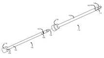
- FIG. 1is a perspective view of an embodiment of an elongate member of the present invention shown adjacent a cannula;
- FIG. 2is a perspective cut-away view of a cannula with an embodiment an elongate member of the present invention inserted into the cannula;
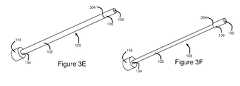
- FIGS. 3A-3Fare perspective views of various embodiments of elongate members of the present invention.
- FIG. 4is a perspective cut-away view a cannula with an alternate embodiment of an elongate member of the present invention inserted into the cannula;
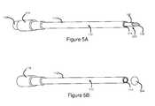
- FIG. 5Ais a perspective view of another embodiment of an elongate member of the present invention shown inserted into a cannula;
- FIG. 5Bis a perspective view of the cannula of FIG. 5A , showing the location of a lesion formed therefrom;
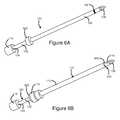
- FIG. 6Ais a perspective view of an embodiment of an elongate member of the present invention comprising a depth stopper
- FIG. 6Bis a perspective view of the elongate member of FIG. 6A , shown inserted into a cannula;
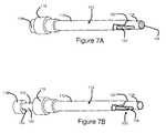
- FIG. 7Ais a perspective view of an embodiment of an elongate member of the present invention inserted to a first position within a cannula;
- FIG. 7Bis a perspective view of the elongate member of FIG. 7A inserted to a predetermined insertion depth within a cannula.
- embodiments of the present inventioncomprise an elongate member for inserting into a cannula.
- the cannulacomprises an electrically insulated region and an electrically exposed conductive region for delivering energy to form a lesion within a patient's body at an intended location relative to the electrically exposed conductive region.
- the elongate memberis structured to cooperatively engage with the cannula at a pre-determined insertion depth, and to provide a variation in radiopacity at a pre-determined position relative to the electrically exposed conductive region when inserted to the pre-determined insertion depth.
- the variation in radiopacityprovides a visual reference for distinguishing, using fluoroscopic imaging, the intended location of the lesion.
- embodiments of the present inventioncomprise an elongate member for inserting into a cannula.
- the cannulacomprises an electrically insulated region and an electrically exposed conductive region for delivering energy to form a lesion within a patient's body at an intended location relative to the electrically exposed conductive region.
- the radiopacity of the elongate membervaries at a pre-determined region of the elongate member, such that when the elongate member is inserted into the cannula to a predetermined insertion depth, the pre-determined region substantially longitudinally aligns with a distal end of the electrically insulated region.
- the variation in radiopacityprovides a visual reference for distinguishing, using fluoroscopic imaging, the intended location of the lesion.
- kitscomprising a cannula and an elongate member for inserting into the cannula.
- the cannulacomprises an electrically insulated region and an electrically exposed conductive region for delivering energy to form a lesion within a patient's body at an intended location relative to the electrically exposed conductive region.
- the elongate memberis structured to cooperatively engage with the cannula at a pre-determined insertion depth and to provide a variation in radiopacity at a pre-determined position relative to the electrically exposed conductive region when inserted to the pre-determined insertion depth.
- the variation in radiopacityprovides a visual reference for distinguishing, using fluoroscopic imaging, the intended location of the lesion.
- embodiments of the present inventioncomprise a method for positioning an electrosurgical apparatus.
- the apparatuscomprises a cannula and an elongate member for inserting into the cannula.
- the cannulacomprises an electrically insulated region, and an electrically exposed conductive region for delivering energy to form a lesion at a target site within a patient's body.
- the elongate memberis structured to cooperatively engage with the cannula at a pre-determined insertion depth, and to provide a variation in radiopacity at a pre-determined position relative to the electrically exposed conductive region when inserted to the pre-determined insertion depth.
- the methodcomprises the steps of: inserting the cannula to a position near a target site in the patient's body; inserting the elongate member into the cannula; determining the location of the lesion to be made by visualizing the location of the variation in radiopacity; and, responsive to determining the location of the lesion to be made, moving the apparatus, if necessary, to position the electrically exposed conductive region such that at least a portion of the target site is located within the location of lesion to be made.
- Elongate member 100comprises a proximal region 102 ending in proximal end 104 , and a distal region 106 ending in distal end 108 .
- Elongate member 100is sized to be inserted into a cannula.
- An embodiment of a cannula suitable for use with an elongate member of the present inventionwill presently be described; however, it is to be noted that elongate member 100 is not limited to use with any particular cannula.
- a cannula 110 suitable for use with elongate member 100is shown in FIG. 1 .
- Cannula 110comprises an electrically insulated region 112 , and an electrically exposed conductive region 114 .
- cannula 110may be percutaneously inserted into a patient's body, and may be connected to a source of energy, for example a radiofrequency generator.
- Cannula 110may be connected to the source of energy directly, for example via a wire or cable, or indirectly, for example via a probe inserted into the cannula.
- Energyis delivered from electrically exposed conductive region 114 to form a lesion at an intended location in the patient's body.
- the intended location of the lesion relative to electrically exposed conductive region 114may vary depending on the structure of electrically exposed conductive region 114 . In the embodiment of FIG. 1 , wherein electrically exposed conductive region 114 is substantially elongate, a substantially ovoid lesion 124 will form around the electrically exposed conductive region.
- Elongate member 100is structured to cooperatively engage with cannula 110 at a predetermined insertion depth. That is, elongate member 100 is structured to be inserted into cannula 110 such that at a particular point during insertion, elongate member 100 and cannula 110 will cooperatively engage to resist further insertion, or to indicate to the user that the pre-determined insertion depth has been reached.
- the cooperative engagementis provided by a hub 116 at proximal end 104 of elongate member 100 , which will contact and substantially abut with a hub 118 at the proximal end of cannula 110 , and prevent further insertion.
- Hub 116may be manufactured from ABS (acrylonitrile butadiene styrene) or a similar material, and may be attached to elongate member 100 using various methods, including but not limited to insert molding, gluing and other forms of bonding.
- Elongate member 100is structured to provide a variation in radiopacity at a predetermined position relative to electrically exposed conductive region 114 when inserted to the predetermined insertion depth.
- elongate member 100is structured such that, when inserted into cannula 110 to the predetermined insertion depth, there will be a visible (using fluoroscopic imaging, for example) change in radiopacity of the combined apparatus (comprising cannula 110 and elongate member 100 ) at a predetermined position relative to electrically exposed conductive region 114 .
- the structure providing this variation in radiopacitymay be referred to as a means for providing a variation in radiopacity.
- the variation in radiopacitymay be provided in numerous ways, as will be described hereinbelow.
- more than one predetermined position relative to electrically exposed conductive region 114may be provided to identify different intended locations of a lesion to be formed depending on the particular application.
- fluoroscopic imagingsimilar to other forms of X-ray imaging, typically produces a flat, two dimensional image, showing the cumulative radiopacity of any structures present along a given line between the X-ray source and the image recording plane.
- the imagewill show the cumulative radiopacity of both elongate member 100 as well as cannula 110 . Therefore, although the embodiments of the present invention describe structural variations on elongate member 100 that provide the variation in radiopacity, the predetermined position, i.e. the location along the combined apparatus at which the change in radiopacity is visible, will be described with reference to the locations along cannula 110 at which this variation in radiopacity is visible under two-dimensional fluoroscopic imaging.
- the predetermined position 200when elongate member 100 is inserted to the pre-determined insertion depth, the predetermined position 200 , at which the variation in radiopacity of the combined apparatus is provided, is at the distal end 120 of the electrically insulated region 112 .
- lesion 124may form substantially around electrically exposed conductive region 114 .
- the predetermined position 200is at distal end 120 of electrically insulated region 112 , when elongate member 100 and cannula 110 are viewed under fluoroscopy, the variation in radiopacity at predetermined position 200 will provide a visual reference for distinguishing the intended location of the lesion.
- the variation in radiopacity at predetermined position 200will provide a visual reference aligned with the proximal-most region of the lesion. It is to be noted that, although the variation in radiopacity provides a visual reference for distinguishing the intended location of the lesion, it is not necessary for elongate member 100 to be in contact with the patient's body at the intended location of the lesion.
- the means for providing the variation in radiopacitywill be located within the cannula lumen when the elongate member is inserted to the pre-determined insertion depth, and thus the elongate member and/or the means for providing the variation in radiopacity may not contact the patient's body at the intended location of the lesion; however, when viewed under fluoroscopy, the variation in radiopacity will provide a visual reference at the intended location of the lesion.
- the variation in radiopacityis provided by a radiopaque marker 122 positioned to substantially longitudinally align with a distal end 120 of electrically insulated region 112 of cannula 110 when elongate member 100 is inserted to the predetermined insertion depth.
- Radiopaque marker 122may be any addition of material to elongate member 100 , which, when inserted into cannula 110 and viewed under fluoroscopy, will appear enhanced with respect to the remainder of the combined apparatus.
- ‘enhanced’refers to increased radiopacity, which typically appears darker on a fluoroscopic image.
- radiopaque marker 122may be a band of a high density metal or alloy such as platinum, iridium, gold, silver or tantalum or alloys or combinations thereof. Such materials are highly visible under fluoroscopic imaging and are therefore visible even at minimal thicknesses. Radiopaque marker 122 may completely circumscribe elongate member 100 , as shown in the embodiment of FIGS. 1 and 2 , or it may only partially circumscribe elongate member 100 . For example, in some embodiments (not shown), radiopaque marker 122 may only traverse 180° of the circumference of elongate member 100 .
- Radiopaque marker 122may be laser welded to elongate member 100 , thus improving the heat resistance of the band-to-member bond.
- radiopaque marker 122may be applied using any other suitable technique, including but not limited to vapor deposition, ion implantation, dip coating, metal plating, welding, soldering, gluing, and electro plating.
- radiopaque marker 122may be fused onto elongate member 100 .
- Radiopaque marker 122may be of various widths, wherein ‘width’ refers to the distance between a proximal edge and a distal edge of radiopaque marker 122 .
- radiopaque marker 122may have a width of between about 1 mm and about 2 mm (approximately 0.04-0.08 inches), more specifically between about 1.2 and about 1.3 mm (approximately 0.045-0.055 inches).
- radiopaque markers of various shapes and patternsmay be applied to elongate member 100 by, for example, the use of various masking techniques.
- the variation in radiopacityis provided by a radiopaque marker 300 which may run parallel to the longitudinal axis of elongate member 100 , along the portion of elongate member 100 that is located at electrically conductive exposed region 114 of cannula 110 when elongate member 100 is inserted to the pre-determined insertion depth.
- the variation in radiopacitywhen viewed under fluoroscopy, will indicate the location of electrically exposed conductive region 114 substantially along its entire length, thus providing a visual reference for distinguishing the intended location of the lesion.
- two radiopaque markersare used to provide variations in radiopacity at two locations.
- the first marker 122may be positioned to substantially longitudinally align with a distal end 120 of the electrically insulated region 112 of cannula 110 when elongate member 100 is inserted to the predetermined insertion depth
- the second marker 123may be positioned to substantially longitudinally align with the distal end of electrically exposed conductive region 114 of cannula 110 when elongate member 100 is inserted to the predetermined insertion depth.
- the radiopaque markers 122 , 123when viewed under fluoroscopy, would provide and/or define a frame for electrically exposed conductive region 114 , and thereby would provide a visual reference for distinguishing the intended location of the lesion.
- the variation in radiopacityis provided by a reduction in the radiopacity of a portion of elongate member 100 .
- Thismay be accomplished by removing material from a portion of elongate member 100 .
- elongate member 100may comprise an indentation 302 , which is positioned to substantially longitudinally align with the distal end 120 of electrically insulated region 112 when elongate member 100 is inserted to the predetermined insertion depth.
- Indentation 302may be any reduction in material, which, when viewed under fluoroscopy, will appear to have diminished intensity when compared with the remainder of elongate member 100 and cannula 110 .
- indentation 302may comprise a notch, groove or recess in elongate member 100 .
- Indentation 302may substantially circumscribe elongate member 100 , as shown in FIG. 3C , or may be located on only a portion of the circumference of elongate member 100 , as shown in FIG. 3D .
- Indentation 302may be formed by various grinding techniques, or by any other means of removing material.
- Indentation 302may be of various widths, wherein ‘width’ refers to the distance between a proximal edge and a distal edge of indentation 302 .
- indentation 302may have a width of between about 1 mm and about 2 mm (approximately 0.04-0.08 inches), more specifically between about 1.2 and about 1.3 mm (approximately 0.045-0.055 inches). In an alternate embodiment, indentation 302 may run parallel to the longitudinal axis of elongate member 100 , along the portion of elongate member 100 that is to be located at electrically conductive exposed region 114 of cannula 110 .
- proximal region 102 and distal region 106 of elongate member 102may be of differing radiopacity.
- Proximal region 102 and distal region 106are sized such that the boundary 304 between proximal region 102 and distal region 106 substantially longitudinally aligns with the distal end 120 of electrically insulated region 112 when elongate member 100 is inserted to the pre-determined insertion depth.
- proximal region 102may be made from a material that is substantially more radiopaque than distal region 106 . Thus, when viewed under fluoroscopy, proximal region 102 will appear enhanced relative to distal region 106 .
- proximal region 102may be made from stainless steel, and distal region 106 may be made from a plastic.
- both of distal region 106 and proximal region 102may be made from the same material, and proximal region 102 may be coated with a material of higher radiopacity.
- distal region 106 and proximal region 102may both be made from stainless steel, and proximal region 102 may be electroplated with platinum.
- proximal region 102may be made from a material that is substantially less radiopaque that distal region 106 . Thus, when viewed under fluoroscopy, proximal region 102 will appear with diminished intensity relative to distal region 106 .
- proximal region 102may be made from a plastic
- distal region 106may be made from a stainless steel.
- the boundary 304 between proximal region 102 and distal region 106provides the visual reference for distinguishing, using fluoroscopic imaging, the intended location of the lesion.
- distal region 106may have a larger transverse cross-sectional area than proximal region 102 , and proximal region 102 and distal region 106 may be sized such that the boundary 304 between proximal region 102 and distal region 106 substantially longitudinally aligns with the distal end 120 of electrically insulated region 112 when elongate member 100 is inserted to the pre-determined insertion depth.
- distal region 106may be sized such that it substantially radially fills the lumen of cannula 110
- proximal region 102may be sized such that it radially fills only a portion of the lumen of cannula 110 .
- proximal region 102when viewed under fluoroscopy, proximal region 102 will appear to have diminished intensity relative to distal region 106 .
- the boundary 304 between proximal region 102 and distal region 106provides the visual reference for distinguishing, using fluoroscopic imaging, the intended location of the lesion.
- distal region 106may have a smaller transverse cross-sectional area than proximal region 102 .
- elongate member 100may be sized such that, when inserted to the pre-determined insertion depth, distal end 108 of elongate member 100 is substantially longitudinally aligned with a distal end 120 of electrically insulated region 112 . That is, in some embodiments, elongate member 100 may be substantially shorter than cannula 110 , such that when inserted to the pre-determined insertion depth, elongate member 100 does not extend substantially into electrically conductive exposed region 114 of cannula 110 .
- elongate member 100may not be shorter than cannula 100 , but rather, elongate member 100 may be structured such that, when inserted to the predetermined insertion depth, a portion of proximal region 102 may remain outside of cannula 110 . This may be accomplished by placing a depth stopper on elongate member 110 to provide the cooperative engagement. This embodiment will be described further hereinbelow with reference to FIG. 7 .
- distal end 108 of elongate member 100is substantially longitudinally aligned with a distal end 120 of electrically insulated region 112 , when the combined apparatus is viewed under fluoroscopy, electrically insulated region 112 will appear enhanced relative to electrically exposed conductive region 114 .
- distal end 108 of elongate member 100provides the visual reference for distinguishing, using fluoroscopic imaging, the intended location of the lesion.
- cannula 110may be structured such that electrically insulated region 112 extends to the distal end of cannula 110 , and electrically exposed conductive region 114 comprises substantially only the distal face of cannula 110 .
- the distal face of cannula 110is shown in FIGS. 5A and 5B as being flat, it may have other shapes as well, including but not limited to rounded or hemispherical shapes.
- cannula 110may be structured such that, during the delivery of energy, at least a portion of cannula 110 is cooled, for example by the insertion of an internally cooled probe into cannula 110 . Further details regarding such embodiments are provided in U.S.
- the intended location of the lesionmay be located substantially distally relative to electrically exposed conductive region 114 , and may or may not contact electrically exposed conductive region 114 .
- elongate member 100may be sized such that when it is inserted to the predetermined insertion depth, a portion of distal region 106 of elongate member 100 extends beyond a distal end of cannula 110 , to the intended location of the lesion 524 . That is, elongate member 100 may be longer than cannula 110 .
- the portion of elongate member 100 that extends beyond the distal end of cannula 110will appear to have diminished intensity relative to cannula 102 .
- the variation in radiopacityis provided by the portion of distal region 106 of elongate member 100 that extends beyond the distal end of cannula 110 .
- lesion 524will form at the location to which distal region 106 extended.
- distal end 108 of elongate member 100may substantially indicate the location where a lesion will form when energy is delivered from cannula 110 .
- elongate member 100is structured to cooperatively engage with cannula 110 at a predetermined insertion depth.
- this cooperative engagementmay be provided by a hub 116 at the proximal end of elongate member 100 .
- this cooperative engagementmay be provided by a depth stopper or other means for substantially preventing longitudinal motion of elongate member 100 , relative to cannula 110 . Referring to FIG. 6A , a depth stopper 600 is shown on elongate member 100 .
- depth stopper 600is an annular component disposed around elongate member 100 , which will contact and abut with hub 118 of cannula 110 when elongate member 100 is inserted to the predetermined insertion depth, as shown in FIG. 6B .
- the means for substantially preventing longitudinal motionmay be any other structure that, during the insertion of elongate member 100 into cannula 110 , will resist further insertion, or indicate to the user that the pre-determined insertion depth has been reached, for example a clip or a clamp.
- the distal end 108 of elongate member 100may be substantially sharp.
- distal end 108may be beveled, as shown in FIGS. 1 , 2 , and 6 .
- distal end 108 of elongate member 100may be substantially blunt, as shown in FIGS. 3 and 4 .
- other shapesare possible, for example rounded, conical, or trocar, and the invention is not limited in this regard.
- the distal end of cannula 110is beveled.
- distal end 116 of elongate member 100may be beveled at the same angle so as to be flush with the distal end of cannula 110 when elongate member 100 is inserted to the predetermined insertion depth.
- Elongate member 100may be manufactured from a number of materials, and the invention is not limited in this regard. Suitable materials include stainless steel, titanium, nitinol, any alloys or combinations thereof, or other materials that may impart varying degrees of flexibility and strength to elongate member 100 . In some embodiments, different portions of elongate member 100 may be manufactured from different materials. For example, it the embodiment of FIG. 3E , proximal region 102 may be manufactured from stainless steel, and distal region 106 may be manufactured from polycarbonate.
- cannula 110may be curved or bent.
- elongate member 100may also be curved or bent, in order fit within the lumen of cannula 110 .
- An electrosurgical system incorporating an elongate member of the present inventionmay further comprise any or all of an energy generator, one or more cannulae, for example cannula 110 , one or more probes, a reference electrode, one or more occluding members, and electrical connections, for examples wires and/or cables, as described, for example, in U.S. patent application Ser. No. 11/079,318, previously incorporated herein by reference.
- high frequency electrical currentflows from a generator via electrical connections to a probe and via the probe to an electrically exposed conductive region of the cannula. This delivery of energy may result in electrical stimulation or high frequency heating of tissue in the region around the electrically exposed conductive region.
- a method embodiment of the present inventionmay be particularly useful for precisely positioning an electrosurgical apparatus, where accurate knowledge of the area to be treated is critical. In facet joint denervation, for example, it is critical that certain nerves, for example those of the sympathetic chain, are not damaged during the treatment procedure.
- a radiofrequency treatment procedure, using an elongate member of the present inventionmay be performed as follows: With a patient lying prone on a radiolucent table, a cannula, for example cannula 110 , is inserted into the patient's body. In some embodiments, an elongate member, for example elongate member 100 , is inserted into the cannula to a pre-determined insertion depth prior to the insertion of the cannula into the patient's body.
- the elongate membermay substantially occlude the lumen of the cannula, in order to aid in insertion.
- the elongate memberis inserted into the cannula to a pre-determined insertion depth after the cannula has been inserted into the patient's body.
- an occluding memberfor example a stylet, may be inserted into the cannula prior to the insertion of the cannula into the patient's body. The occluding member may be removed from the cannula after the cannula has been inserted into the patient's body, and the elongate member may then be inserted into the cannula.
- the elongate membermay be inserted into the cannula to a first position, for example as shown in FIG. 7A , whereby at the first position the elongate member substantially occludes the distal end of the cannula for aiding in the insertion of the cannula.
- the cannula and elongate membermay then be inserted into the patient's body to a position near the target location.
- the elongate membermay then be repositioned to the predetermined insertion depth, for example as shown in FIG.
- the usermay determine the location of the lesion to be made. That is, the elongate member and cannula may be visualized under fluoroscopy, such that the variation in radiopacity provided by the elongate member provides a visual reference for determining the location of the lesion to be made.
- the elongate membercomprises a radiopaque marker substantially longitudinally aligned with the distal end of the electrically insulated region of the cannula
- the distal end of the electrically insulated region of the cannulawill appear enhanced relative to the remainder of the cannula. This enhanced region serves as a visual reference for the user, indicating to the user that the proximal-most region of the lesion will be at the enhanced region visible on the fluoroscopic image.
- the usermay determine that it is necessary to move the cannula. For example, the target nerve may not be within the previously determined location of the lesion to be made. Thus, the user may move the cannula to precisely position the electrically exposed conductive region such that at least a portion of the target site is located within the location of the lesion to be made.
- the elongate membermay be removed and replaced by a radiofrequency probe.
- the location of a target nerve within the target sitemay be confirmed by sensory stimulation.
- energymay be delivered from an energy generator through the probe to the active tip of the cannula in order to create a lesion about the target nerve.
- anesthetic or other diagnostic or therapeutic agentsmay be injected through the cannula.
- the method aspect of the present inventionalso provides for the insertion of multiple cannulae and multiple elongate members of the present invention over the course of a treatment procedure, whereby any or all of the cannulae and elongate members may be positioned under fluoroscopic guidance, as described herein above.
- energymay be delivered directly to the cannula from the energy generator, for example via one or more wires or cables connected directly to the cannula.
- the elongate membermay be operable to be connected to the energy generator such that energy may be delivered from the energy generator, via the elongate member, to the electrically conductive exposed region of the cannula.
- embodiments of the present inventioncomprise an elongate member for inserting into a cannula.
- the cannulamay comprise an electrically insulated region and an electrically exposed conductive region for delivering energy to form a lesion within a patient's body at an intended location relative to the electrically exposed conductive region.
- the elongate memberis structured to cooperatively engage with the cannula at a pre-determined insertion depth, and to provide a variation in radiopacity at a pre-determined position relative to the electrically exposed conductive region when inserted to the pre-determined insertion depth.
- the variation in radiopacityprovides a visual reference for distinguishing, using fluoroscopic imaging, the intended location of the lesion.
- Embodiments of the present inventionallow a user to determine, with greater precision than previously possible, the location where a lesion will be formed during an electrosurgical procedure. This allows the user to more precisely position the cannula to ensure that the target of energy delivery will indeed be encompassed by the lesion.
- the outer profile of the cannularemains unchanged, such that the force required to insert the cannula within the patient's body is not increased.
Landscapes
- Health & Medical Sciences (AREA)
- Surgery (AREA)
- Engineering & Computer Science (AREA)
- Life Sciences & Earth Sciences (AREA)
- Biomedical Technology (AREA)
- Otolaryngology (AREA)
- Nuclear Medicine, Radiotherapy & Molecular Imaging (AREA)
- Plasma & Fusion (AREA)
- Physics & Mathematics (AREA)
- Heart & Thoracic Surgery (AREA)
- Medical Informatics (AREA)
- Molecular Biology (AREA)
- Animal Behavior & Ethology (AREA)
- General Health & Medical Sciences (AREA)
- Public Health (AREA)
- Veterinary Medicine (AREA)
- Surgical Instruments (AREA)
Abstract
Description
Claims (11)
Priority Applications (1)
| Application Number | Priority Date | Filing Date | Title |
|---|---|---|---|
| US11/733,515US9216053B2 (en) | 2002-03-05 | 2007-04-10 | Elongate member providing a variation in radiopacity |
Applications Claiming Priority (18)
| Application Number | Priority Date | Filing Date | Title |
|---|---|---|---|
| US10/087,856US6896675B2 (en) | 2002-03-05 | 2002-03-05 | Intradiscal lesioning device |
| US10/382,836US20040176759A1 (en) | 2003-03-07 | 2003-03-07 | Radiopaque electrical needle |
| US10/853,126US20050267552A1 (en) | 2004-05-26 | 2004-05-26 | Electrosurgical device |
| US10/864,410US7163536B2 (en) | 2004-06-10 | 2004-06-10 | Determining connections of multiple energy sources and energy delivery devices |
| US60434804P | 2004-08-25 | 2004-08-25 | |
| US11/079,318US7593778B2 (en) | 2003-03-07 | 2005-03-15 | Electrosurgical device with improved visibility |
| US11/105,490US20050177209A1 (en) | 2002-03-05 | 2005-04-14 | Bipolar tissue treatment system |
| US11/105,524US7294127B2 (en) | 2002-03-05 | 2005-04-14 | Electrosurgical tissue treatment method |
| US11/105,527US8882755B2 (en) | 2002-03-05 | 2005-04-14 | Electrosurgical device for treatment of tissue |
| US11/125,247US7306596B2 (en) | 2004-05-26 | 2005-05-10 | Multifunctional electrosurgical apparatus |
| US59555905P | 2005-07-14 | 2005-07-14 | |
| US59556005P | 2005-07-14 | 2005-07-14 | |
| US11/207,707US20050277918A1 (en) | 2003-03-07 | 2005-08-22 | Electrosurgical cannula |
| US74351106P | 2006-03-16 | 2006-03-16 | |
| US74451806P | 2006-04-10 | 2006-04-10 | |
| US11/381,783US20060259026A1 (en) | 2005-05-05 | 2006-05-05 | Electrosurgical treatment method and device |
| US11/457,697US10206739B2 (en) | 2002-03-05 | 2006-07-14 | Electrosurgical device and methods |
| US11/733,515US9216053B2 (en) | 2002-03-05 | 2007-04-10 | Elongate member providing a variation in radiopacity |
Related Parent Applications (1)
| Application Number | Title | Priority Date | Filing Date |
|---|---|---|---|
| US11/457,697Continuation-In-PartUS10206739B2 (en) | 2002-03-05 | 2006-07-14 | Electrosurgical device and methods |
Publications (2)
| Publication Number | Publication Date |
|---|---|
| US20070203402A1 US20070203402A1 (en) | 2007-08-30 |
| US9216053B2true US9216053B2 (en) | 2015-12-22 |
Family
ID=38444949
Family Applications (1)
| Application Number | Title | Priority Date | Filing Date |
|---|---|---|---|
| US11/733,515Active2027-09-19US9216053B2 (en) | 2002-03-05 | 2007-04-10 | Elongate member providing a variation in radiopacity |
Country Status (1)
| Country | Link |
|---|---|
| US (1) | US9216053B2 (en) |
Cited By (11)
| Publication number | Priority date | Publication date | Assignee | Title |
|---|---|---|---|---|
| US10905440B2 (en) | 2008-09-26 | 2021-02-02 | Relievant Medsystems, Inc. | Nerve modulation systems |
| US11007010B2 (en) | 2019-09-12 | 2021-05-18 | Relevant Medsysterns, Inc. | Curved bone access systems |
| US11160563B2 (en) | 2012-11-05 | 2021-11-02 | Relievant Medsystems, Inc. | Systems for navigation and treatment within a vertebral body |
| US11471210B2 (en) | 2011-12-30 | 2022-10-18 | Relievant Medsystems, Inc. | Methods of denervating vertebral body using external energy source |
| US11596468B2 (en) | 2002-09-30 | 2023-03-07 | Relievant Medsystems, Inc. | Intraosseous nerve treatment |
| US11690667B2 (en) | 2012-09-12 | 2023-07-04 | Relievant Medsystems, Inc. | Radiofrequency ablation of tissue within a vertebral body |
| US12039731B2 (en) | 2020-12-22 | 2024-07-16 | Relievant Medsystems, Inc. | Prediction of candidates for spinal neuromodulation |
| US12082876B1 (en) | 2020-09-28 | 2024-09-10 | Relievant Medsystems, Inc. | Introducer drill |
| US12193719B2 (en) | 2013-08-08 | 2025-01-14 | Relievant Medsystems, Inc. | Modulating nerves within bone |
| US12303166B2 (en) | 2008-09-26 | 2025-05-20 | Relievant Medsystems, Inc. | Methods for accessing nerves within bone |
| US12433668B1 (en) | 2021-11-08 | 2025-10-07 | Relievant Medsystems, Inc. | Impedance stoppage mitigation during radiofrequency tissue ablation procedures |
Families Citing this family (5)
| Publication number | Priority date | Publication date | Assignee | Title |
|---|---|---|---|---|
| US8145918B2 (en)* | 2007-06-28 | 2012-03-27 | International Business Machines Corporation | Monitoring system processes energy consumption |
| EP3556308B1 (en) | 2009-11-05 | 2023-12-20 | Stratus Medical, LLC | Systems for spinal radio frequency neurotomy |
| KR101632429B1 (en) | 2010-05-21 | 2016-06-21 | 님버스 컨셉츠, 엘엘씨 | Systems and methods for tissue ablation |
| US8939969B2 (en)* | 2011-09-30 | 2015-01-27 | Kimberly-Clark, Inc. | Electrosurgical device with offset conductive element |
| US12042133B2 (en)* | 2021-05-07 | 2024-07-23 | Arthrex, Inc. | System providing improved visibility for minimally invasive surgery systems |
Citations (123)
| Publication number | Priority date | Publication date | Assignee | Title |
|---|---|---|---|---|
| US4041931A (en) | 1976-05-17 | 1977-08-16 | Elliott Donald P | Radiopaque anastomosis marker |
| US4202349A (en) | 1978-04-24 | 1980-05-13 | Jones James W | Radiopaque vessel markers |
| US4257429A (en) | 1979-02-07 | 1981-03-24 | Medtronic, Inc. | Stylet retainer and extension |
| WO1981003272A1 (en) | 1980-05-13 | 1981-11-26 | American Hospital Supply Corp | A multipolar electrosurgical device |
| US4419095A (en) | 1980-05-14 | 1983-12-06 | Shiley, Inc. | Cannula with radiopaque tip |
| US4447239A (en) | 1979-03-19 | 1984-05-08 | Dr. Eduard Fresenius Chemisch-Pharmazeutishe Industry Kg | Catheter with radiographic contrast strips |
| US4548027A (en) | 1983-11-11 | 1985-10-22 | Kubota, Ltd. | Combine harvester |
| US4612934A (en) | 1981-06-30 | 1986-09-23 | Borkan William N | Non-invasive multiprogrammable tissue stimulator |
| US4657024A (en) | 1980-02-04 | 1987-04-14 | Teleflex Incorporated | Medical-surgical catheter |
| US5191900A (en) | 1991-04-10 | 1993-03-09 | The Board Of Trustees Of The University Of Illinois | Dialysis probe |
| US5209749A (en) | 1990-05-11 | 1993-05-11 | Applied Urology Inc. | Fluoroscopically alignable cutter assembly and method of using the same |
| EP0547772A1 (en) | 1991-12-16 | 1993-06-23 | Dexide, Inc. | Laparoscopic instrument |
| WO1994002077A3 (en) | 1992-07-15 | 1994-04-14 | Angelase Inc | Ablation catheter system |
| WO1994009560A1 (en) | 1992-10-15 | 1994-04-28 | Correa Paulo N | Energy conversion system |
| US5342357A (en) | 1992-11-13 | 1994-08-30 | American Cardiac Ablation Co., Inc. | Fluid cooled electrosurgical cauterization system |
| US5342343A (en) | 1991-08-28 | 1994-08-30 | Uni-Charm Corporation | Disposable training pants |
| WO1994022384A1 (en) | 1993-03-29 | 1994-10-13 | Boston Scientific Corporation | Electro-coagulation and ablation and other electrotherapeutic treatments of body tissue |
| WO1994024948A1 (en) | 1992-04-23 | 1994-11-10 | Scimed Life Systems, Inc. | Apparatus and method for sealing vascular punctures |
| US5397338A (en) | 1993-03-29 | 1995-03-14 | Maven Labs, Inc. | Electrotherapy device |
| EP0642800A1 (en) | 1993-09-09 | 1995-03-15 | Citation Medical Corporation | Irrigation probe assembly |
| WO1995010318A1 (en) | 1993-10-14 | 1995-04-20 | Ep Technologies, Inc. | Electrode elements for forming lesion patterns |
| WO1995010327A1 (en) | 1993-10-14 | 1995-04-20 | Ep Technologies, Inc. | Curvilinear electrode and method for forming lesions |
| WO1995010320A1 (en) | 1993-10-15 | 1995-04-20 | Ep Technologies, Inc. | Device for lengthening cardiac conduction pathways |
| US5429597A (en) | 1994-03-01 | 1995-07-04 | Boston Scientific Corporation | Kink resistant balloon catheter and method for use |
| US5429617A (en) | 1993-12-13 | 1995-07-04 | The Spectranetics Corporation | Radiopaque tip marker for alignment of a catheter within a body |
| US5433739A (en) | 1993-11-02 | 1995-07-18 | Sluijter; Menno E. | Method and apparatus for heating an intervertebral disc for relief of back pain |
| WO1995021578A1 (en) | 1994-02-09 | 1995-08-17 | Keravision, Inc. | An electrosurgical procedure recurving the cornea |
| US5458597A (en)* | 1993-11-08 | 1995-10-17 | Zomed International | Device for treating cancer and non-malignant tumors and methods |
| US5545193A (en) | 1993-10-15 | 1996-08-13 | Ep Technologies, Inc. | Helically wound radio-frequency emitting electrodes for creating lesions in body tissue |
| US5571147A (en) | 1993-11-02 | 1996-11-05 | Sluijter; Menno E. | Thermal denervation of an intervertebral disc for relief of back pain |
| WO1996039967A1 (en) | 1995-06-07 | 1996-12-19 | Ep Technologies, Inc. | Tissue heating and ablation systems and methods which predict maximum tissue temperature |
| WO1997024074A1 (en) | 1995-12-29 | 1997-07-10 | Microgyn, Inc. | Apparatus and method for electrosurgery |
| US5683384A (en)* | 1993-11-08 | 1997-11-04 | Zomed | Multiple antenna ablation apparatus |
| US5693043A (en) | 1985-03-22 | 1997-12-02 | Massachusetts Institute Of Technology | Catheter for laser angiosurgery |
| WO1998019613A1 (en) | 1996-11-08 | 1998-05-14 | Surx, Inc. | Devices, methods and systems for shrinking tissues |
| US5759174A (en) | 1997-01-29 | 1998-06-02 | Cathco, Inc. | Angioplasty balloon with an expandable external radiopaque marker band |
| WO1998027879A1 (en) | 1996-12-20 | 1998-07-02 | Electroscope, Inc. | Bipolar coagulation apparatus and method for arthroscopy |
| US5776092A (en) | 1994-03-23 | 1998-07-07 | Erbe Elektromedizin Gmbh | Multifunctional surgical instrument |
| US5779642A (en) | 1996-01-16 | 1998-07-14 | Nightengale; Christopher | Interrogation device and method |
| US5800428A (en) | 1996-05-16 | 1998-09-01 | Angeion Corporation | Linear catheter ablation system |
| EP0865768A1 (en) | 1997-03-19 | 1998-09-23 | Raymond S. Kasevich | Topical radio frequency thermal treatment of targeted volumes |
| WO1998031290A9 (en) | 1998-01-15 | 1998-12-23 | Bipolar vaporization apparatus and method for arthroscopy | |
| WO1998058747A1 (en) | 1997-06-20 | 1998-12-30 | Board Of Regents, The University Of Texas System | Method and apparatus for electromagnetic powder deposition |
| US5855577A (en) | 1996-09-17 | 1999-01-05 | Eclipse Surgical Technologies, Inc. | Bow shaped catheter |
| WO1999042037A1 (en) | 1998-02-20 | 1999-08-26 | Arthrocare Corporation | Systems and methods for electrosurgical spine surgery |
| WO1999043263A1 (en) | 1998-02-27 | 1999-09-02 | Conway-Stuart Medical, Inc. | Apparatus to electrosurgically treat esophageal sphincters |
| US5951546A (en) | 1994-12-13 | 1999-09-14 | Lorentzen; Torben | Electrosurgical instrument for tissue ablation, an apparatus, and a method for providing a lesion in damaged and diseased tissue from a mammal |
| WO1999048548A1 (en) | 1998-03-23 | 1999-09-30 | Medtronic, Inc. | Catheter having extruded radiopaque stripes embedded in soft tip and method of fabrication |
| US6002964A (en) | 1998-07-15 | 1999-12-14 | Feler; Claudio A. | Epidural nerve root stimulation |
| US6056743A (en) | 1997-11-04 | 2000-05-02 | Scimed Life Systems, Inc. | Percutaneous myocardial revascularization device and method |
| EP0651661B1 (en) | 1993-04-22 | 2000-06-28 | C.R. Bard, Inc. | Improved composite irrigation and suction probe |
| US6102886A (en) | 1992-08-12 | 2000-08-15 | Vidamed, Inc. | Steerable medical probe with stylets |
| US6104957A (en) | 1998-08-21 | 2000-08-15 | Alo; Kenneth M. | Epidural nerve root stimulation with lead placement method |
| US6126654A (en) | 1997-04-04 | 2000-10-03 | Eclipse Surgical Technologies, Inc. | Method of forming revascularization channels in myocardium using a steerable catheter |
| US6129726A (en) | 1992-08-12 | 2000-10-10 | Vidamed, Inc. | Medical probe device and method |
| US6146380A (en) | 1998-01-09 | 2000-11-14 | Radionics, Inc. | Bent tip electrical surgical probe |
| US6176857B1 (en) | 1997-10-22 | 2001-01-23 | Oratec Interventions, Inc. | Method and apparatus for applying thermal energy to tissue asymmetrically |
| US20010000041A1 (en) | 1997-12-19 | 2001-03-15 | Selmon Matthew R. | Methods and apparatus for crossing vascular occlusions |
| US6235000B1 (en) | 1998-01-13 | 2001-05-22 | Lumend, Inc. | Apparatus for crossing total occlusion in blood vessels |
| US6251104B1 (en) | 1995-05-10 | 2001-06-26 | Eclipse Surgical Technologies, Inc. | Guiding catheter system for ablating heart tissue |
| WO2001045579A1 (en) | 1999-12-21 | 2001-06-28 | Sherwood Services Ag | Apparatus for thermal treatment of an intervertebral disc |
| US6280441B1 (en) | 1997-12-15 | 2001-08-28 | Sherwood Services Ag | Apparatus and method for RF lesioning |
| WO2001070114A1 (en) | 2000-03-17 | 2001-09-27 | Rita Medical Systems Inc. | Lung treatment apparatus |
| US20010027309A1 (en) | 1996-04-30 | 2001-10-04 | Medtronic, Inc. | Therapeutic method for treatment of alzheimer's disease |
| US6306132B1 (en) | 1999-06-17 | 2001-10-23 | Vivant Medical | Modular biopsy and microwave ablation needle delivery apparatus adapted to in situ assembly and method of use |
| US6315790B1 (en) | 1999-06-07 | 2001-11-13 | Scimed Life Systems, Inc. | Radiopaque marker bands |
| US6330478B1 (en)* | 1995-08-15 | 2001-12-11 | Rita Medical Systems, Inc. | Cell necrosis apparatus |
| US20010056280A1 (en) | 1992-01-07 | 2001-12-27 | Underwood Ronald A. | Systems and methods for electrosurgical spine surgery |
| WO2001074251A3 (en) | 2000-03-31 | 2002-01-31 | Rita Medical Systems Inc | Tissue biopsy and treatment apparatus and method |
| US20020032440A1 (en) | 2000-04-27 | 2002-03-14 | Hooven Michael D. | Transmural ablation device and method |
| US6379349B1 (en) | 1995-11-08 | 2002-04-30 | Celon Ag Medical Instruments | Arrangement for electrothermal treatment of the human or animal body |
| US20020072739A1 (en) | 2000-12-07 | 2002-06-13 | Roberta Lee | Methods and devices for radiofrequency electrosurgery |
| WO2001067975A3 (en) | 2000-03-15 | 2002-07-04 | Gary M Onik | Combined electrosurgical-cryosurgical instrument |
| US20020091384A1 (en) | 2000-04-27 | 2002-07-11 | Hooven Michael D. | Transmural ablation device with integral EKG sensor |
| US20020103484A1 (en) | 2000-04-27 | 2002-08-01 | Hooven Michael D. | Transmural ablation device with thermocouple for measuring tissue temperature |
| US20020120260A1 (en) | 2001-02-28 | 2002-08-29 | Morris David L. | Tissue surface treatment apparatus and method |
| US20020147485A1 (en) | 2000-11-15 | 2002-10-10 | George Mamo | Minimally invasive apparatus for implanting a sacral stimulation lead |
| US6464723B1 (en) | 1999-04-22 | 2002-10-15 | Advanced Cardiovascular Systems, Inc. | Radiopaque stents |
| US6471700B1 (en) | 1998-04-08 | 2002-10-29 | Senorx, Inc. | Apparatus and method for accessing biopsy site |
| US6478793B1 (en) | 1999-06-11 | 2002-11-12 | Sherwood Services Ag | Ablation treatment of bone metastases |
| US20020193781A1 (en) | 2001-06-14 | 2002-12-19 | Loeb Marvin P. | Devices for interstitial delivery of thermal energy into tissue and methods of use thereof |
| US6501992B1 (en) | 2000-10-17 | 2002-12-31 | Medtronic, Inc. | Radiopaque marking of lead electrode zone in a continuous conductor construction |
| US20030014047A1 (en) | 1995-06-07 | 2003-01-16 | Jean Woloszko | Apparatus and methods for treating cervical inter-vertebral discs |
| US20030015707A1 (en) | 2001-07-17 | 2003-01-23 | Motorola, Inc. | Integrated radio frequency , optical, photonic, analog and digital functions in a semiconductor structure and method for fabricating semiconductor structure utilizing the formation of a compliant substrate for materials used to form the same |
| US20030023239A1 (en) | 1998-03-03 | 2003-01-30 | Senorx, Inc. | Apparatus and method for accessing a body site |
| US20030032936A1 (en) | 2001-08-10 | 2003-02-13 | Lederman Robert J. | Side-exit catheter and method for its use |
| US6562033B2 (en) | 2001-04-09 | 2003-05-13 | Baylis Medical Co. | Intradiscal lesioning apparatus |
| US20030093007A1 (en) | 2001-10-17 | 2003-05-15 | The Government Of The U.S.A., As Represented By The Secretary, Department Of Health And Human Serv | Biopsy apparatus with radio frequency cauterization and methods for its use |
| US20030100895A1 (en) | 2001-11-28 | 2003-05-29 | Simpson John A. | Dielectric-coated ablation electrode having a non-coated window with thermal sensors |
| WO2003065917A1 (en) | 2002-02-08 | 2003-08-14 | Oratec Interventions, Inc. | An electrosurgical instrument having a predetermined heat profile |
| US20030158545A1 (en) | 2000-09-28 | 2003-08-21 | Arthrocare Corporation | Methods and apparatus for treating back pain |
| US6620156B1 (en) | 2002-09-20 | 2003-09-16 | Jon C. Garito | Bipolar tonsillar probe |
| US6622731B2 (en) | 2001-01-11 | 2003-09-23 | Rita Medical Systems, Inc. | Bone-treatment instrument and method |
| US20030212394A1 (en)* | 2001-05-10 | 2003-11-13 | Rob Pearson | Tissue ablation apparatus and method |
| US20030212395A1 (en) | 2000-05-12 | 2003-11-13 | Arthrocare Corporation | Systems and methods for electrosurgery |
| US20030233125A1 (en) | 2002-06-12 | 2003-12-18 | Alfred E. Mann Institute For Biomedical Engineering At The University Of S. California | Injection devices for unimpeded target location testing |
| WO2003103522A1 (en) | 2002-06-10 | 2003-12-18 | Map Technologies Llc | Methods and devices for electrosurgical electrolysis |
| US6689127B1 (en)* | 1995-08-15 | 2004-02-10 | Rita Medical Systems | Multiple antenna ablation apparatus and method with multiple sensor feedback |
| US20040054366A1 (en) | 1998-08-11 | 2004-03-18 | Arthrocare Corporation | Instrument for electrosurgical tissue treatment |
| US20040082942A1 (en) | 2002-10-23 | 2004-04-29 | Katzman Scott S. | Visualizing ablation device and procedure |
| US6735474B1 (en) | 1998-07-06 | 2004-05-11 | Advanced Bionics Corporation | Implantable stimulator system and method for treatment of incontinence and pain |
| US20040106891A1 (en) | 2002-08-30 | 2004-06-03 | Inrad, Inc. | Localizing needle with fluid delivery |
| US6773446B1 (en) | 2000-08-02 | 2004-08-10 | Cordis Corporation | Delivery apparatus for a self-expanding stent |
| US6780181B2 (en) | 1998-06-22 | 2004-08-24 | St. Jude Medical, Daig Division, Inc. | Even temperature linear lesion ablation catheter |
| US20040187875A1 (en) | 2001-05-01 | 2004-09-30 | He Sheng Ding | Method and apparatus for altering conduction properties along pathways in the heart and in vessels in conductive communication with the heart. |
| US20040199161A1 (en) | 2003-02-14 | 2004-10-07 | Surgrx, Inc., A Delaware Corporation | Electrosurgical probe and method of use |
| US20040215287A1 (en) | 2003-04-25 | 2004-10-28 | Medtronic, Inc. | Implantabe trial neurostimulation device |
| US20040249373A1 (en) | 2001-06-21 | 2004-12-09 | Gronemeyer Dietrich H.W | Needle electrode |
| US20040267203A1 (en) | 2003-06-26 | 2004-12-30 | Potter Daniel J. | Splittable cannula having radiopaque marker |
| US20040267254A1 (en) | 2003-06-30 | 2004-12-30 | Intuitive Surgical, Inc., A Delaware Corporation | Electro-surgical instrument with replaceable end-effectors and inhibited surface conduction |
| US20050033372A1 (en) | 2002-09-06 | 2005-02-10 | Medtronic, Inc. | Method, system and device for treating disorders of the pelvic floor by electrical stimulation of the left and the right sacral nerves |
| US20050049570A1 (en)* | 1998-03-06 | 2005-03-03 | Yem Chin | Apparatus and method for establishing access to the body |
| US20050085806A1 (en) | 2002-06-06 | 2005-04-21 | Map Technologies, Llc | Methods and devices for electrosurgery |
| US20050096718A1 (en) | 2003-10-31 | 2005-05-05 | Medtronic, Inc. | Implantable stimulation lead with fixation mechanism |
| US6893421B1 (en)* | 2000-08-08 | 2005-05-17 | Scimed Life Systems, Inc. | Catheter shaft assembly |
| US20050177211A1 (en) | 2002-03-05 | 2005-08-11 | Baylis Medical Company Inc. | Electrosurgical device for treatment of tissue |
| US20050177209A1 (en) | 2002-03-05 | 2005-08-11 | Baylis Medical Company Inc. | Bipolar tissue treatment system |
| US20050187542A1 (en) | 2000-08-18 | 2005-08-25 | Map Technologies, Llc | Devices for electrosurgery |
| US6966902B2 (en) | 1996-05-14 | 2005-11-22 | Edwards Lifesciences Corporation | Balloon occlusion device and methods of use |
| US20060020297A1 (en) | 2004-07-20 | 2006-01-26 | Gerber Martin T | Neurostimulation system with distributed stimulators |
| US20060025763A1 (en) | 2000-08-21 | 2006-02-02 | Dale Nelson | Ablation catheter with cooled linear electrode |
| US7097641B1 (en) | 1999-12-09 | 2006-08-29 | Cryocath Technologies Inc. | Catheter with cryogenic and heating ablation |
| US7175631B2 (en) | 2000-05-25 | 2007-02-13 | Synthes (U.S.A.) | Radiolucent aiming guide |
Family Cites Families (1)
| Publication number | Priority date | Publication date | Assignee | Title |
|---|---|---|---|---|
| AU6274898A (en) | 1997-01-15 | 1998-08-07 | Electroscope, Inc. | Bipolar vaporization apparatus and method for arthroscopy |
- 2007
- 2007-04-10USUS11/733,515patent/US9216053B2/enactiveActive
Patent Citations (153)
| Publication number | Priority date | Publication date | Assignee | Title |
|---|---|---|---|---|
| US4041931A (en) | 1976-05-17 | 1977-08-16 | Elliott Donald P | Radiopaque anastomosis marker |
| US4202349A (en) | 1978-04-24 | 1980-05-13 | Jones James W | Radiopaque vessel markers |
| US4257429A (en) | 1979-02-07 | 1981-03-24 | Medtronic, Inc. | Stylet retainer and extension |
| US4447239A (en) | 1979-03-19 | 1984-05-08 | Dr. Eduard Fresenius Chemisch-Pharmazeutishe Industry Kg | Catheter with radiographic contrast strips |
| US4657024A (en) | 1980-02-04 | 1987-04-14 | Teleflex Incorporated | Medical-surgical catheter |
| WO1981003272A1 (en) | 1980-05-13 | 1981-11-26 | American Hospital Supply Corp | A multipolar electrosurgical device |
| CA1160932A (en) | 1980-05-14 | 1984-01-24 | Perry A. Nebergall | Cannula with radiopaque tip |
| US4419095A (en) | 1980-05-14 | 1983-12-06 | Shiley, Inc. | Cannula with radiopaque tip |
| US4612934A (en) | 1981-06-30 | 1986-09-23 | Borkan William N | Non-invasive multiprogrammable tissue stimulator |
| US4548027A (en) | 1983-11-11 | 1985-10-22 | Kubota, Ltd. | Combine harvester |
| US5693043A (en) | 1985-03-22 | 1997-12-02 | Massachusetts Institute Of Technology | Catheter for laser angiosurgery |
| US5209749A (en) | 1990-05-11 | 1993-05-11 | Applied Urology Inc. | Fluoroscopically alignable cutter assembly and method of using the same |
| US5191900A (en) | 1991-04-10 | 1993-03-09 | The Board Of Trustees Of The University Of Illinois | Dialysis probe |
| US5342343A (en) | 1991-08-28 | 1994-08-30 | Uni-Charm Corporation | Disposable training pants |
| EP0547772A1 (en) | 1991-12-16 | 1993-06-23 | Dexide, Inc. | Laparoscopic instrument |
| US20010056280A1 (en) | 1992-01-07 | 2001-12-27 | Underwood Ronald A. | Systems and methods for electrosurgical spine surgery |
| WO1994024948A1 (en) | 1992-04-23 | 1994-11-10 | Scimed Life Systems, Inc. | Apparatus and method for sealing vascular punctures |
| WO1994002077A3 (en) | 1992-07-15 | 1994-04-14 | Angelase Inc | Ablation catheter system |
| US6102886A (en) | 1992-08-12 | 2000-08-15 | Vidamed, Inc. | Steerable medical probe with stylets |
| US6129726A (en) | 1992-08-12 | 2000-10-10 | Vidamed, Inc. | Medical probe device and method |
| WO1994009560A1 (en) | 1992-10-15 | 1994-04-28 | Correa Paulo N | Energy conversion system |
| US5342357A (en) | 1992-11-13 | 1994-08-30 | American Cardiac Ablation Co., Inc. | Fluid cooled electrosurgical cauterization system |
| WO1994022384A1 (en) | 1993-03-29 | 1994-10-13 | Boston Scientific Corporation | Electro-coagulation and ablation and other electrotherapeutic treatments of body tissue |
| US5397338A (en) | 1993-03-29 | 1995-03-14 | Maven Labs, Inc. | Electrotherapy device |
| EP0651661B1 (en) | 1993-04-22 | 2000-06-28 | C.R. Bard, Inc. | Improved composite irrigation and suction probe |
| EP0642800A1 (en) | 1993-09-09 | 1995-03-15 | Citation Medical Corporation | Irrigation probe assembly |
| WO1995010327A1 (en) | 1993-10-14 | 1995-04-20 | Ep Technologies, Inc. | Curvilinear electrode and method for forming lesions |
| WO1995010318A1 (en) | 1993-10-14 | 1995-04-20 | Ep Technologies, Inc. | Electrode elements for forming lesion patterns |
| WO1995010320A1 (en) | 1993-10-15 | 1995-04-20 | Ep Technologies, Inc. | Device for lengthening cardiac conduction pathways |
| US5545193A (en) | 1993-10-15 | 1996-08-13 | Ep Technologies, Inc. | Helically wound radio-frequency emitting electrodes for creating lesions in body tissue |
| US5433739A (en) | 1993-11-02 | 1995-07-18 | Sluijter; Menno E. | Method and apparatus for heating an intervertebral disc for relief of back pain |
| US5571147A (en) | 1993-11-02 | 1996-11-05 | Sluijter; Menno E. | Thermal denervation of an intervertebral disc for relief of back pain |
| US5683384A (en)* | 1993-11-08 | 1997-11-04 | Zomed | Multiple antenna ablation apparatus |
| US5458597A (en)* | 1993-11-08 | 1995-10-17 | Zomed International | Device for treating cancer and non-malignant tumors and methods |
| US5429617A (en) | 1993-12-13 | 1995-07-04 | The Spectranetics Corporation | Radiopaque tip marker for alignment of a catheter within a body |
| US20020049437A1 (en) | 1994-02-09 | 2002-04-25 | Thomas A. Silvestrini | Electrosurgical procedure for the treatment of the cornea |
| US5766171A (en) | 1994-02-09 | 1998-06-16 | Keravision, Inc. | Electrosurgical procedure for the treatment of the cornea |
| WO1995021578A1 (en) | 1994-02-09 | 1995-08-17 | Keravision, Inc. | An electrosurgical procedure recurving the cornea |
| US5429597A (en) | 1994-03-01 | 1995-07-04 | Boston Scientific Corporation | Kink resistant balloon catheter and method for use |
| US5776092A (en) | 1994-03-23 | 1998-07-07 | Erbe Elektromedizin Gmbh | Multifunctional surgical instrument |
| US5951546A (en) | 1994-12-13 | 1999-09-14 | Lorentzen; Torben | Electrosurgical instrument for tissue ablation, an apparatus, and a method for providing a lesion in damaged and diseased tissue from a mammal |
| US6251104B1 (en) | 1995-05-10 | 2001-06-26 | Eclipse Surgical Technologies, Inc. | Guiding catheter system for ablating heart tissue |
| US20030014047A1 (en) | 1995-06-07 | 2003-01-16 | Jean Woloszko | Apparatus and methods for treating cervical inter-vertebral discs |
| WO1996039967A1 (en) | 1995-06-07 | 1996-12-19 | Ep Technologies, Inc. | Tissue heating and ablation systems and methods which predict maximum tissue temperature |
| US6330478B1 (en)* | 1995-08-15 | 2001-12-11 | Rita Medical Systems, Inc. | Cell necrosis apparatus |
| WO1997006739A3 (en) | 1995-08-15 | 1998-05-07 | Edward J Gough | Apparatus for ablation of a selected mass |
| US6689127B1 (en)* | 1995-08-15 | 2004-02-10 | Rita Medical Systems | Multiple antenna ablation apparatus and method with multiple sensor feedback |
| WO1997006855A3 (en) | 1995-08-15 | 1998-08-06 | Edward J Gough | Apparatus for ablation of a selected mass |
| EP1344497A1 (en) | 1995-08-15 | 2003-09-17 | Rita Medical Systems, Inc. | Rf apparatus for the ablation of selected mass |
| US6379349B1 (en) | 1995-11-08 | 2002-04-30 | Celon Ag Medical Instruments | Arrangement for electrothermal treatment of the human or animal body |
| WO1997024074A1 (en) | 1995-12-29 | 1997-07-10 | Microgyn, Inc. | Apparatus and method for electrosurgery |
| US5779642A (en) | 1996-01-16 | 1998-07-14 | Nightengale; Christopher | Interrogation device and method |
| US20010027309A1 (en) | 1996-04-30 | 2001-10-04 | Medtronic, Inc. | Therapeutic method for treatment of alzheimer's disease |
| US6966902B2 (en) | 1996-05-14 | 2005-11-22 | Edwards Lifesciences Corporation | Balloon occlusion device and methods of use |
| US5800428A (en) | 1996-05-16 | 1998-09-01 | Angeion Corporation | Linear catheter ablation system |
| US6277112B1 (en) | 1996-07-16 | 2001-08-21 | Arthrocare Corporation | Methods for electrosurgical spine surgery |
| US6726684B1 (en) | 1996-07-16 | 2004-04-27 | Arthrocare Corporation | Methods for electrosurgical spine surgery |
| US5855577A (en) | 1996-09-17 | 1999-01-05 | Eclipse Surgical Technologies, Inc. | Bow shaped catheter |
| WO1998019613A1 (en) | 1996-11-08 | 1998-05-14 | Surx, Inc. | Devices, methods and systems for shrinking tissues |
| US20030195593A1 (en)* | 1996-11-08 | 2003-10-16 | Surx, Inc. | Devices, methods, and systems for shrinking tissues |
| WO1998027879A1 (en) | 1996-12-20 | 1998-07-02 | Electroscope, Inc. | Bipolar coagulation apparatus and method for arthroscopy |
| US5895386A (en) | 1996-12-20 | 1999-04-20 | Electroscope, Inc. | Bipolar coagulation apparatus and method for arthroscopy |
| US5759174A (en) | 1997-01-29 | 1998-06-02 | Cathco, Inc. | Angioplasty balloon with an expandable external radiopaque marker band |
| EP0865768A1 (en) | 1997-03-19 | 1998-09-23 | Raymond S. Kasevich | Topical radio frequency thermal treatment of targeted volumes |
| US6126654A (en) | 1997-04-04 | 2000-10-03 | Eclipse Surgical Technologies, Inc. | Method of forming revascularization channels in myocardium using a steerable catheter |
| WO1998058747A1 (en) | 1997-06-20 | 1998-12-30 | Board Of Regents, The University Of Texas System | Method and apparatus for electromagnetic powder deposition |
| US6176857B1 (en) | 1997-10-22 | 2001-01-23 | Oratec Interventions, Inc. | Method and apparatus for applying thermal energy to tissue asymmetrically |
| US6056743A (en) | 1997-11-04 | 2000-05-02 | Scimed Life Systems, Inc. | Percutaneous myocardial revascularization device and method |
| US6280441B1 (en) | 1997-12-15 | 2001-08-28 | Sherwood Services Ag | Apparatus and method for RF lesioning |
| US20010000041A1 (en) | 1997-12-19 | 2001-03-15 | Selmon Matthew R. | Methods and apparatus for crossing vascular occlusions |
| US6146380A (en) | 1998-01-09 | 2000-11-14 | Radionics, Inc. | Bent tip electrical surgical probe |
| US6235000B1 (en) | 1998-01-13 | 2001-05-22 | Lumend, Inc. | Apparatus for crossing total occlusion in blood vessels |
| US20030120195A1 (en) | 1998-01-13 | 2003-06-26 | Lumend, Inc. | Re-entry catheter |
| WO1998031290A9 (en) | 1998-01-15 | 1998-12-23 | Bipolar vaporization apparatus and method for arthroscopy | |
| US20030040742A1 (en) | 1998-02-20 | 2003-02-27 | Arthrocare Corporation | Systems and methods for electrosurgical spine surgery |
| WO1999042037A1 (en) | 1998-02-20 | 1999-08-26 | Arthrocare Corporation | Systems and methods for electrosurgical spine surgery |
| WO1999043263A1 (en) | 1998-02-27 | 1999-09-02 | Conway-Stuart Medical, Inc. | Apparatus to electrosurgically treat esophageal sphincters |
| US20030023239A1 (en) | 1998-03-03 | 2003-01-30 | Senorx, Inc. | Apparatus and method for accessing a body site |
| US20050049570A1 (en)* | 1998-03-06 | 2005-03-03 | Yem Chin | Apparatus and method for establishing access to the body |
| WO1999048548A1 (en) | 1998-03-23 | 1999-09-30 | Medtronic, Inc. | Catheter having extruded radiopaque stripes embedded in soft tip and method of fabrication |
| US6471700B1 (en) | 1998-04-08 | 2002-10-29 | Senorx, Inc. | Apparatus and method for accessing biopsy site |
| US6780181B2 (en) | 1998-06-22 | 2004-08-24 | St. Jude Medical, Daig Division, Inc. | Even temperature linear lesion ablation catheter |
| US6735474B1 (en) | 1998-07-06 | 2004-05-11 | Advanced Bionics Corporation | Implantable stimulator system and method for treatment of incontinence and pain |
| US6002964A (en) | 1998-07-15 | 1999-12-14 | Feler; Claudio A. | Epidural nerve root stimulation |
| US20040054366A1 (en) | 1998-08-11 | 2004-03-18 | Arthrocare Corporation | Instrument for electrosurgical tissue treatment |
| US6104957A (en) | 1998-08-21 | 2000-08-15 | Alo; Kenneth M. | Epidural nerve root stimulation with lead placement method |
| US6464723B1 (en) | 1999-04-22 | 2002-10-15 | Advanced Cardiovascular Systems, Inc. | Radiopaque stents |
| US6315790B1 (en) | 1999-06-07 | 2001-11-13 | Scimed Life Systems, Inc. | Radiopaque marker bands |
| US6478793B1 (en) | 1999-06-11 | 2002-11-12 | Sherwood Services Ag | Ablation treatment of bone metastases |
| US6306132B1 (en) | 1999-06-17 | 2001-10-23 | Vivant Medical | Modular biopsy and microwave ablation needle delivery apparatus adapted to in situ assembly and method of use |
| US6355033B1 (en) | 1999-06-17 | 2002-03-12 | Vivant Medical | Track ablation device and methods of use |
| US6582426B2 (en) | 1999-06-17 | 2003-06-24 | Vivant Medical, Inc. | Needle kit and method for microwave ablation, track coagulation, and biopsy |
| US7097641B1 (en) | 1999-12-09 | 2006-08-29 | Cryocath Technologies Inc. | Catheter with cryogenic and heating ablation |
| WO2001045579A1 (en) | 1999-12-21 | 2001-06-28 | Sherwood Services Ag | Apparatus for thermal treatment of an intervertebral disc |
| WO2001067975A3 (en) | 2000-03-15 | 2002-07-04 | Gary M Onik | Combined electrosurgical-cryosurgical instrument |
| WO2001070114A1 (en) | 2000-03-17 | 2001-09-27 | Rita Medical Systems Inc. | Lung treatment apparatus |
| US6770070B1 (en) | 2000-03-17 | 2004-08-03 | Rita Medical Systems, Inc. | Lung treatment apparatus and method |
| US20020026127A1 (en) | 2000-03-23 | 2002-02-28 | Balbierz Daniel J. | Tissue biopsy and treatment apparatus and method |
| WO2001074251A3 (en) | 2000-03-31 | 2002-01-31 | Rita Medical Systems Inc | Tissue biopsy and treatment apparatus and method |
| US20020091384A1 (en) | 2000-04-27 | 2002-07-11 | Hooven Michael D. | Transmural ablation device with integral EKG sensor |
| US6974454B2 (en) | 2000-04-27 | 2005-12-13 | Atricure, Inc. | Transmural ablation device with thermocouple for measuring tissue temperature |
| US6932811B2 (en) | 2000-04-27 | 2005-08-23 | Atricure, Inc. | Transmural ablation device with integral EKG sensor |
| US20020103484A1 (en) | 2000-04-27 | 2002-08-01 | Hooven Michael D. | Transmural ablation device with thermocouple for measuring tissue temperature |
| US20020032440A1 (en) | 2000-04-27 | 2002-03-14 | Hooven Michael D. | Transmural ablation device and method |
| US20030125729A1 (en) | 2000-04-27 | 2003-07-03 | Hooven Michael D. | Transmural ablation device |
| WO2001080724B1 (en) | 2000-04-27 | 2002-05-10 | Atricure Inc | Transmural ablation device and method |
| US7462178B2 (en) | 2000-05-12 | 2008-12-09 | Arthrocare Corporation | Systems and methods for electrosurgical spine surgery |
| US20030212395A1 (en) | 2000-05-12 | 2003-11-13 | Arthrocare Corporation | Systems and methods for electrosurgery |
| US7270658B2 (en) | 2000-05-12 | 2007-09-18 | Arthrocare Corporation | Systems and methods for electrosurgery |
| US7175631B2 (en) | 2000-05-25 | 2007-02-13 | Synthes (U.S.A.) | Radiolucent aiming guide |
| US6773446B1 (en) | 2000-08-02 | 2004-08-10 | Cordis Corporation | Delivery apparatus for a self-expanding stent |
| US6893421B1 (en)* | 2000-08-08 | 2005-05-17 | Scimed Life Systems, Inc. | Catheter shaft assembly |
| US20050187542A1 (en) | 2000-08-18 | 2005-08-25 | Map Technologies, Llc | Devices for electrosurgery |
| US20060025763A1 (en) | 2000-08-21 | 2006-02-02 | Dale Nelson | Ablation catheter with cooled linear electrode |
| US20030158545A1 (en) | 2000-09-28 | 2003-08-21 | Arthrocare Corporation | Methods and apparatus for treating back pain |
| US6501992B1 (en) | 2000-10-17 | 2002-12-31 | Medtronic, Inc. | Radiopaque marking of lead electrode zone in a continuous conductor construction |
| US20020147485A1 (en) | 2000-11-15 | 2002-10-10 | George Mamo | Minimally invasive apparatus for implanting a sacral stimulation lead |
| US20050240238A1 (en) | 2000-11-15 | 2005-10-27 | Medtronic, Inc. | Minimally invasive apparatus for implanting a sacral stimulation lead |
| US6847849B2 (en) | 2000-11-15 | 2005-01-25 | Medtronic, Inc. | Minimally invasive apparatus for implanting a sacral stimulation lead |
| WO2002045609A1 (en) | 2000-12-07 | 2002-06-13 | Rubicor Medical, Inc. | Methods and devices for radiofrequency electrosurgery |
| US20030109870A1 (en) | 2000-12-07 | 2003-06-12 | Rubicor Medical, Inc. | Methods and devices for radiofrequency electrosurgery |
| US20020072739A1 (en) | 2000-12-07 | 2002-06-13 | Roberta Lee | Methods and devices for radiofrequency electrosurgery |
| US6622731B2 (en) | 2001-01-11 | 2003-09-23 | Rita Medical Systems, Inc. | Bone-treatment instrument and method |
| US20020120260A1 (en) | 2001-02-28 | 2002-08-29 | Morris David L. | Tissue surface treatment apparatus and method |
| US6562033B2 (en) | 2001-04-09 | 2003-05-13 | Baylis Medical Co. | Intradiscal lesioning apparatus |
| US20040187875A1 (en) | 2001-05-01 | 2004-09-30 | He Sheng Ding | Method and apparatus for altering conduction properties along pathways in the heart and in vessels in conductive communication with the heart. |
| US20030212394A1 (en)* | 2001-05-10 | 2003-11-13 | Rob Pearson | Tissue ablation apparatus and method |
| US20020193781A1 (en) | 2001-06-14 | 2002-12-19 | Loeb Marvin P. | Devices for interstitial delivery of thermal energy into tissue and methods of use thereof |
| US20040249373A1 (en) | 2001-06-21 | 2004-12-09 | Gronemeyer Dietrich H.W | Needle electrode |
| US20030015707A1 (en) | 2001-07-17 | 2003-01-23 | Motorola, Inc. | Integrated radio frequency , optical, photonic, analog and digital functions in a semiconductor structure and method for fabricating semiconductor structure utilizing the formation of a compliant substrate for materials used to form the same |
| US20030032936A1 (en) | 2001-08-10 | 2003-02-13 | Lederman Robert J. | Side-exit catheter and method for its use |
| US20030093007A1 (en) | 2001-10-17 | 2003-05-15 | The Government Of The U.S.A., As Represented By The Secretary, Department Of Health And Human Serv | Biopsy apparatus with radio frequency cauterization and methods for its use |
| WO2003037162A3 (en) | 2001-10-26 | 2003-09-18 | Atricure Inc | Transmural ablation device with integral ekg sensor |
| US20030100895A1 (en) | 2001-11-28 | 2003-05-29 | Simpson John A. | Dielectric-coated ablation electrode having a non-coated window with thermal sensors |
| US6757565B2 (en) | 2002-02-08 | 2004-06-29 | Oratec Interventions, Inc. | Electrosurgical instrument having a predetermined heat profile |
| WO2003065917A1 (en) | 2002-02-08 | 2003-08-14 | Oratec Interventions, Inc. | An electrosurgical instrument having a predetermined heat profile |
| US20030153906A1 (en) | 2002-02-08 | 2003-08-14 | Sharkey Hugh R. | Electrosurgical instrument having a predetermined heat profile |
| US20050177211A1 (en) | 2002-03-05 | 2005-08-11 | Baylis Medical Company Inc. | Electrosurgical device for treatment of tissue |
| US20050177209A1 (en) | 2002-03-05 | 2005-08-11 | Baylis Medical Company Inc. | Bipolar tissue treatment system |
| US20050085806A1 (en) | 2002-06-06 | 2005-04-21 | Map Technologies, Llc | Methods and devices for electrosurgery |
| WO2003103522A1 (en) | 2002-06-10 | 2003-12-18 | Map Technologies Llc | Methods and devices for electrosurgical electrolysis |
| US20030233125A1 (en) | 2002-06-12 | 2003-12-18 | Alfred E. Mann Institute For Biomedical Engineering At The University Of S. California | Injection devices for unimpeded target location testing |
| US20040106891A1 (en) | 2002-08-30 | 2004-06-03 | Inrad, Inc. | Localizing needle with fluid delivery |
| US20050033372A1 (en) | 2002-09-06 | 2005-02-10 | Medtronic, Inc. | Method, system and device for treating disorders of the pelvic floor by electrical stimulation of the left and the right sacral nerves |
| US6620156B1 (en) | 2002-09-20 | 2003-09-16 | Jon C. Garito | Bipolar tonsillar probe |
| US20040082942A1 (en) | 2002-10-23 | 2004-04-29 | Katzman Scott S. | Visualizing ablation device and procedure |
| US6902526B2 (en) | 2002-10-23 | 2005-06-07 | Orthopaedic Development, Llc | Visualizing ablation device and procedure |
| US20040199161A1 (en) | 2003-02-14 | 2004-10-07 | Surgrx, Inc., A Delaware Corporation | Electrosurgical probe and method of use |
| US20040215287A1 (en) | 2003-04-25 | 2004-10-28 | Medtronic, Inc. | Implantabe trial neurostimulation device |
| US20040267203A1 (en) | 2003-06-26 | 2004-12-30 | Potter Daniel J. | Splittable cannula having radiopaque marker |
| US20040267254A1 (en) | 2003-06-30 | 2004-12-30 | Intuitive Surgical, Inc., A Delaware Corporation | Electro-surgical instrument with replaceable end-effectors and inhibited surface conduction |
| US20050096718A1 (en) | 2003-10-31 | 2005-05-05 | Medtronic, Inc. | Implantable stimulation lead with fixation mechanism |
| US20060020297A1 (en) | 2004-07-20 | 2006-01-26 | Gerber Martin T | Neurostimulation system with distributed stimulators |
Non-Patent Citations (47)
Cited By (24)
| Publication number | Priority date | Publication date | Assignee | Title |
|---|---|---|---|---|
| US11596468B2 (en) | 2002-09-30 | 2023-03-07 | Relievant Medsystems, Inc. | Intraosseous nerve treatment |
| US12329412B2 (en) | 2008-09-26 | 2025-06-17 | Relievant Medsystems, Inc. | Systems for accessing nerves within bone |
| US12303166B2 (en) | 2008-09-26 | 2025-05-20 | Relievant Medsystems, Inc. | Methods for accessing nerves within bone |
| US12161350B2 (en) | 2008-09-26 | 2024-12-10 | Relievant Medsystems, Inc. | Systems for treating nerves within bone using steam |
| US10905440B2 (en) | 2008-09-26 | 2021-02-02 | Relievant Medsystems, Inc. | Nerve modulation systems |
| US11471171B2 (en) | 2008-09-26 | 2022-10-18 | Relievant Medsystems, Inc. | Bipolar radiofrequency ablation systems for treatment within bone |
| US12059193B2 (en) | 2011-12-30 | 2024-08-13 | Relievant Medsystems, Inc. | Methods of denervating vertebral body using external energy source |
| US11471210B2 (en) | 2011-12-30 | 2022-10-18 | Relievant Medsystems, Inc. | Methods of denervating vertebral body using external energy source |
| US11737814B2 (en) | 2012-09-12 | 2023-08-29 | Relievant Medsystems, Inc. | Cryotherapy treatment for back pain |
| US11701168B2 (en) | 2012-09-12 | 2023-07-18 | Relievant Medsystems, Inc. | Radiofrequency ablation of tissue within a vertebral body |
| US11690667B2 (en) | 2012-09-12 | 2023-07-04 | Relievant Medsystems, Inc. | Radiofrequency ablation of tissue within a vertebral body |
| US11234764B1 (en) | 2012-11-05 | 2022-02-01 | Relievant Medsystems, Inc. | Systems for navigation and treatment within a vertebral body |
| US11291502B2 (en) | 2012-11-05 | 2022-04-05 | Relievant Medsystems, Inc. | Methods of navigation and treatment within a vertebral body |
| US11974759B2 (en) | 2012-11-05 | 2024-05-07 | Relievant Medsystems, Inc. | Methods of navigation and treatment within a vertebral body |
| US11160563B2 (en) | 2012-11-05 | 2021-11-02 | Relievant Medsystems, Inc. | Systems for navigation and treatment within a vertebral body |
| US12193719B2 (en) | 2013-08-08 | 2025-01-14 | Relievant Medsystems, Inc. | Modulating nerves within bone |
| US11426199B2 (en) | 2019-09-12 | 2022-08-30 | Relievant Medsystems, Inc. | Methods of treating a vertebral body |
| US11207100B2 (en) | 2019-09-12 | 2021-12-28 | Relievant Medsystems, Inc. | Methods of detecting and treating back pain |
| US11202655B2 (en) | 2019-09-12 | 2021-12-21 | Relievant Medsystems, Inc. | Accessing and treating tissue within a vertebral body |
| US11123103B2 (en) | 2019-09-12 | 2021-09-21 | Relievant Medsystems, Inc. | Introducer systems for bone access |
| US11007010B2 (en) | 2019-09-12 | 2021-05-18 | Relevant Medsysterns, Inc. | Curved bone access systems |
| US12082876B1 (en) | 2020-09-28 | 2024-09-10 | Relievant Medsystems, Inc. | Introducer drill |
| US12039731B2 (en) | 2020-12-22 | 2024-07-16 | Relievant Medsystems, Inc. | Prediction of candidates for spinal neuromodulation |
| US12433668B1 (en) | 2021-11-08 | 2025-10-07 | Relievant Medsystems, Inc. | Impedance stoppage mitigation during radiofrequency tissue ablation procedures |
Also Published As
| Publication number | Publication date |
|---|---|
| US20070203402A1 (en) | 2007-08-30 |
Similar Documents
| Publication | Publication Date | Title |
|---|---|---|
| US9216053B2 (en) | Elongate member providing a variation in radiopacity | |
| US7593778B2 (en) | Electrosurgical device with improved visibility | |
| EP1863558B1 (en) | Electrosurgical cannula | |
| US20210177502A1 (en) | Devices and methods for radiofrequency neurotomy | |
| US20230165631A9 (en) | Devices and methods for forming a fistula | |
| US20220023588A1 (en) | Catheter system | |
| US20100185082A1 (en) | Device and method for electrosurgery | |
| JP4511503B2 (en) | Catheter conductor pair | |
| KR102020831B1 (en) | Electrosurgical device with offset conductive element | |
| US8192425B2 (en) | Radiofrequency perforation apparatus | |
| JP6762704B2 (en) | Catheter with flexible distal tip for mapping and cauterizing tubular areas | |
| US8048071B2 (en) | Method for creating a channel through a foreign material | |
| JP6835809B2 (en) | Electrosurgical device with lumens | |
| US6010500A (en) | Telescoping apparatus and method for linear lesion ablation | |
| US20070066975A1 (en) | Method for creating a channel through an occlusion and apparatus therefor | |
| EP1169972A1 (en) | Mapping and ablation catheter | |
| US20180036060A1 (en) | Electrosurgical generator | |
| JPH11514250A (en) | High resolution intravascular signal detection | |
| US9226788B2 (en) | Fenestration through foreign material | |
| US20250000575A1 (en) | Tissue cutting systems and methods | |
| US20240415570A1 (en) | Devices, systems, and methods for preventing arcing between electrodes for medical procedures | |
| CN118714979A (en) | Tissue cutting system and method |
Legal Events
| Date | Code | Title | Description |
|---|---|---|---|
| AS | Assignment | Owner name:BAYLIS MEDICAL COMPANY INC., CANADA Free format text:ASSIGNMENT OF ASSIGNORS INTEREST;ASSIGNORS:GODARA, NEIL;SHAH, KRISHAN;LEFLER, AMY;AND OTHERS;REEL/FRAME:019261/0065 Effective date:20070412 | |
| AS | Assignment | Owner name:KIMBERLY-CLARK INC.,CANADA Free format text:ASSIGNMENT OF ASSIGNORS INTEREST;ASSIGNOR:BAYLIS MEDICAL COMPANY INC.;REEL/FRAME:023915/0252 Effective date:20091001 Owner name:KIMBERLY-CLARK INC., CANADA Free format text:ASSIGNMENT OF ASSIGNORS INTEREST;ASSIGNOR:BAYLIS MEDICAL COMPANY INC.;REEL/FRAME:023915/0252 Effective date:20091001 | |
| AS | Assignment | Owner name:AVENT INC., GEORGIA Free format text:ASSIGNMENT OF ASSIGNORS INTEREST;ASSIGNOR:KIMBERLY-CLARK INC.;REEL/FRAME:034515/0310 Effective date:20141031 | |
| AS | Assignment | Owner name:MORGAN STANLEY SENIOR FUNDING, INC., NEW YORK Free format text:SECURITY INTEREST;ASSIGNOR:AVENT, INC.;REEL/FRAME:035375/0867 Effective date:20150227 | |
| STCF | Information on status: patent grant | Free format text:PATENTED CASE | |
| AS | Assignment | Owner name:CITIBANK, N.A., NEW YORK Free format text:INTELLECTUAL PROPERTY SECURITY INTEREST ASSIGNMENT AGREEMENT;ASSIGNOR:MORGAN STANLEY SENIOR FUNDING, INC.;REEL/FRAME:048173/0137 Effective date:20181029 | |
| MAFP | Maintenance fee payment | Free format text:PAYMENT OF MAINTENANCE FEE, 4TH YEAR, LARGE ENTITY (ORIGINAL EVENT CODE: M1551); ENTITY STATUS OF PATENT OWNER: LARGE ENTITY Year of fee payment:4 | |
| AS | Assignment | Owner name:JPMORGAN CHASE BANK, N.A., AS ADMINISTRATIVE AGENT, ILLINOIS Free format text:SECURITY INTEREST;ASSIGNOR:AVENT, INC.;REEL/FRAME:060441/0445 Effective date:20220624 | |
| AS | Assignment | Owner name:AVANOS MEDICAL SALES, LLC, GEORGIA Free format text:RELEASE BY SECURED PARTY;ASSIGNOR:CITIBANK, N.A.;REEL/FRAME:060557/0062 Effective date:20220624 Owner name:AVENT, INC., GEORGIA Free format text:RELEASE BY SECURED PARTY;ASSIGNOR:CITIBANK, N.A.;REEL/FRAME:060557/0062 Effective date:20220624 | |
| MAFP | Maintenance fee payment | Free format text:PAYMENT OF MAINTENANCE FEE, 8TH YEAR, LARGE ENTITY (ORIGINAL EVENT CODE: M1552); ENTITY STATUS OF PATENT OWNER: LARGE ENTITY Year of fee payment:8 |