US9212725B2 - Ring gears configured to encase in-line torque transducers for power tools - Google Patents
Ring gears configured to encase in-line torque transducers for power toolsDownload PDFInfo
- Publication number
- US9212725B2 US9212725B2US14/006,206US201114006206AUS9212725B2US 9212725 B2US9212725 B2US 9212725B2US 201114006206 AUS201114006206 AUS 201114006206AUS 9212725 B2US9212725 B2US 9212725B2
- Authority
- US
- United States
- Prior art keywords
- ring gear
- wall
- transducer
- gear body
- length
- Prior art date
- Legal status (The legal status is an assumption and is not a legal conclusion. Google has not performed a legal analysis and makes no representation as to the accuracy of the status listed.)
- Active
Links
Images


Classifications
- F—MECHANICAL ENGINEERING; LIGHTING; HEATING; WEAPONS; BLASTING
- F16—ENGINEERING ELEMENTS AND UNITS; GENERAL MEASURES FOR PRODUCING AND MAINTAINING EFFECTIVE FUNCTIONING OF MACHINES OR INSTALLATIONS; THERMAL INSULATION IN GENERAL
- F16H—GEARING
- F16H1/00—Toothed gearings for conveying rotary motion
- F16H1/28—Toothed gearings for conveying rotary motion with gears having orbital motion
- B—PERFORMING OPERATIONS; TRANSPORTING
- B25—HAND TOOLS; PORTABLE POWER-DRIVEN TOOLS; MANIPULATORS
- B25B—TOOLS OR BENCH DEVICES NOT OTHERWISE PROVIDED FOR, FOR FASTENING, CONNECTING, DISENGAGING OR HOLDING
- B25B21/00—Portable power-driven screw or nut setting or loosening tools; Attachments for drilling apparatus serving the same purpose
- B—PERFORMING OPERATIONS; TRANSPORTING
- B25—HAND TOOLS; PORTABLE POWER-DRIVEN TOOLS; MANIPULATORS
- B25B—TOOLS OR BENCH DEVICES NOT OTHERWISE PROVIDED FOR, FOR FASTENING, CONNECTING, DISENGAGING OR HOLDING
- B25B23/00—Details of, or accessories for, spanners, wrenches, screwdrivers
- B25B23/14—Arrangement of torque limiters or torque indicators in wrenches or screwdrivers
- B25B23/147—Arrangement of torque limiters or torque indicators in wrenches or screwdrivers specially adapted for electrically operated wrenches or screwdrivers
- B—PERFORMING OPERATIONS; TRANSPORTING
- B25—HAND TOOLS; PORTABLE POWER-DRIVEN TOOLS; MANIPULATORS
- B25F—COMBINATION OR MULTI-PURPOSE TOOLS NOT OTHERWISE PROVIDED FOR; DETAILS OR COMPONENTS OF PORTABLE POWER-DRIVEN TOOLS NOT PARTICULARLY RELATED TO THE OPERATIONS PERFORMED AND NOT OTHERWISE PROVIDED FOR
- B25F5/00—Details or components of portable power-driven tools not particularly related to the operations performed and not otherwise provided for
- B25F5/001—Gearings, speed selectors, clutches or the like specially adapted for rotary tools
Definitions
- This inventionrelates to power tools and is particularly suitable for cordless power tools.
- Power toolscan be exposed to repetitive operation that can reduce a lifespan of certain components.
- Power toolstypically include torque transducers to monitor rotational torque generated by a drive train. Monitoring torsion in power tools and other rotating machinery is often desirable. In the case of power tools, such as nutrunners or screwdrivers, the monitored data permits measurement of the rotational torque output and thereby calculation of output produced by the tool.
- Real time feedback coupled with programmable controlsmakes it possible to automatically adjust tool operation, e.g., deactivate the tool power, such as when a desired fastener tension is achieved. This provides the benefit of reproducible fastener tensioning in precision environments and/or assembly line or other mass production operations.
- Power tool drive trainsare typically limited in space and moving parts can damage transducers.
- Embodiments of the inventionare directed to ring gears that can protect transducers from premature breakage due to exposure to operational forces.
- Embodiments of the inventionare directed to ring gear and torque assemblies that can provide accurate torque measurements, protect the transducer from moving parts, and provide for ease of assembly with accurate alignment to position the transducer in concentric alignment with the drive train.
- Some embodimentsare directed to ring gears that include a cylindrical ring gear body having a wall with a longitudinal length extending between opposing first and second ends.
- the wallhas an outer surface and an inner surface.
- the inner surfacehas a first portion that extends a first sub-length of the ring gear body and a longitudinally spaced apart second portion that extends a second sub-length of the ring gear body.
- the first portionextends from the first end of the ring gear inward and the second portion extends from the second end of the ring gear inward.
- the inner surface of the first portionincludes a plurality of longitudinally extending splines and the inner surface of the second portion is devoid of the splines of the first portion.
- the ring gear body inner surfacecan include a circumferentially extending rim between the first and second portions.
- the inner surface of the second portion of the ring gearcan include at least one of: (a) longitudinally extending slots; (b) radially inward projecting, longitudinally extending rails; or (c) at least one each of a longitudinally extending slot and a radially inward projecting, longitudinally extending rail.
- the second portion sub-lengthcan be less than the first portion sub-length.
- the second portioncan have a smooth inner surface.
- the second end of the wallcan have a thickness that is greater than the first end.
- the second portionhas a wall thickness that is greater than the first portion.
- the wallcan have a substantially constant outer diameter.
- the inner surface of the second portion of the ring gearcan include at least two circumferentially spaced apart longitudinally extending rails that project radially inward.
- the inner surfacecan include a circumferentially extending rim positioned between the first and second portions.
- the second portion inner surfacecan include two substantially diametrically opposed longitudinally extending rails that terminate proximate the rim.
- the second portioncan be sized and configured to hold an outerwall of a disk shaped transducer to be flush or held just inward of the second end of the ring gear.
- the first portioncan be sized and configured to surround first and second stage gears of a drive train for a power tool and the second portion can be sized and configured to encase an outer wall of a disk shaped transducer.
- the ring gearcan be in combination with a disk-shaped torque transducer.
- the disk-shaped torque transducerhas a longitudinally extending outer wall with opposing first and second ends and a length therebetween.
- the outer wallmerges radially inward into a thin circular interior flat wall that surrounds a center hub defining an axially extending open channel.
- the transducer outer wall lengthis the same or less than the sub-length of the second portion of the ring gear.
- the transducer outer wallresides encased in the second portion of the ring gear.
- the ring gear second portioncan include a plurality of longitudinally extending circumferentially spaced apart rails and the transducer outer wall can have a plurality of circumferentially spaced apart slots.
- the transducer slotscan matably engage the ring gear rails so that the transducer is held in a locked anti-rotational configuration with respect to the ring gear.
- the power toolincludes a motor having an outwardly extending rotor that defines a drive axis and a drive train coupled to the rotor and configured to drive a tool output.
- the drive trainincludes first and second stage gears and a ring gear with a wall having an inner surface with (i) a first segment having splines that engage the first and second stage gears and (ii) a spaced apart second segment that resides upstream of the first stage gears facing the motor.
- the power toolalso includes a disk-shaped torque transducer having an outer wall that radially merges into a thin flat interior wall having a center hub with an open channel that projects outward toward the motor with a hub center axis that is concentric with the drive axis.
- the transducer outer wallresides encased inside the ring gear second segment in a locked anti-rotational configuration with respect to the ring gear.
- the power toolcan be a cordless power tool.
- the transducer outer wallcan be held substantially flush with an end of the ring gear that faces the motor.
- the ring gearcan include rails and the transducer outer wall can include cooperating slots that slidably receive the rails to lock the transducer to the ring gear.
- the ring gear inner surfacecan include a circumferentially extending rim positioned between the first and second segments so that the transducer abuts the rim when in position in the ring gear.
- the toolcan include a gearcase that surrounds the ring gear and a motor mount that holds the motor and attaches to the gearcase.
- the ring gearis held inside the gearcase between the motor mount and a tapered end of the gearcase to have an axial float clearance on each end of the ring gear so that, during operation, the ring gear floats relative to the gearcase and motor mount.
- the transducer center hubcan have external gear teeth that merges into a stepped wall portion proximate the thin flat center wall.
- the motor mountcan include a transducer engaging segment with splines and a stepped wall segment.
- the motor mount splines of the transducer engaging segmentengage the hub external gear teeth.
- the stepped portion of the transducer center hubmatably engages the stepped segment of the motor mount to concentrically align the hub center axis with the drive axis.
- the motor rotorextends through a front portion of the center hub channel and attaches to a pinion that extends out of a rear portion of the center hub channel.
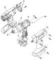
- FIG. 1is a side perspective view of an exemplary cordless power tool according to embodiments of the present invention.
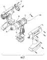
- FIG. 2is an exploded view of the tool shown in FIG. 1 .
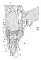
- FIG. 3is a side section view of the power tool shown in FIG. 1 according to embodiments of the present invention.
- FIG. 4is a top section view of a portion of the power tool shown in FIG. 1 according to embodiments of the present invention.
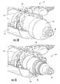
- FIG. 5Ais a side perspective view of a portion of the tool shown in FIG. 1 with the housing illustrated as a transparent component to illustrate positions of certain features according to embodiments of the present invention.
- FIG. 5Bis a partial end perspective view of the tool shown in FIG. 5A , with a part of the housing omitted.
- FIG. 5Cis a partial end perspective view of the tool shown in FIG. 5B with the gearcase also omitted.
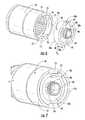
- FIG. 6is a side perspective exploded view of an in-line torque transducer and a ring gear according to embodiments of the present invention.
- FIG. 7is side perspective assembled view of the transducer and ring gear shown in FIG. 6 according to embodiments of the present invention.
- FIG. 8Ais a side perspective exploded view of another embodiment of the torque transducer and ring gear according to embodiments of the present invention.
- FIG. 8Bis a side perspective exploded view of yet another embodiment of the torque transducer and ring gear according to embodiments of the present invention.
- cordless power toolrefers to power tools that do not require plug-in, hard wired electrical connections to an external power source to operate. Rather, the cordless power tools have electric motors that are powered by on-board batteries, such as rechargeable batteries. A range of batteries may fit a range of cordless tools. Different cordless power tools may have a variety of electrical current demand profiles that operate more efficiently with batteries providing a suitable range of voltages and current capacities.
- the different cordless (e.g., battery powered) power toolscan include, for example, screwdrivers, ratchets, nutrunners, impacts and the like.
- Embodiments of the inventionmay be particularly suitable for precision power tool that can be used for applications where more exact control of the applied output is desired.
- FIGS. 1 and 2illustrate an example of a power tool 10 that includes a housing 12 , a motor 14 , a gearcase 16 and a tool output shaft 18 .
- the housing 12encases the motor 14 and partially surrounds the gearcase 16 .
- the gearcase 16encloses a drive train 20 ( FIGS. 3 , 4 ).
- the lower portion of the housingcan releasably engage a battery 120 (shown in broken line in FIG. 1 ).
- the housingcan include an external control such as a trigger 11 and a UI (user interface) 19 with a display.
- the motor 14can be held in a desired fixed position and orientation in the housing 12 using a motor mount 50 ( FIGS. 2 , 3 and 4 ).
- the gearcase 16is rigidly mounted to the motor mount 50 creating a single unified drive train.
- the motor 14can attach (e.g., screw) to the motor mount 50 .
- the gearcase 16can twist to matably lock to the motor mount 50 .
- the gearcase 16 (and encased drive train 20 ) with the motor mount 50 and motor 14can define or form part of a motor sub-assembly 100 that can be placed into the outer housing 12 , which as shown in FIG. 2 , may be provided as two matable components 12 1 , 12 2 .
- the motor 14includes a motor rotor 22 (e.g., motor output shaft) 22 that extends toward the tool output shaft 18 and has a centerline that coincides with a drive train center axis 24 .
- the motor rotor 22is attached to a pinion gear 25 having a plurality of splines or teeth 26 .
- the motor rotor 22drives the pinion 25 which engages the drive train 20 , which thereby drives the tool output shaft 18 .
- the drive train 20includes a first stage of planetary gears 30 and a second stage of planetary gears 35 that reside inside a ring gear 70 .
- the ring gear 70does not itself rotate but defines an outer wall for the planetary gears 30 , 35 .
- the ring gear 70is cylindrical and includes a wall with an inner surface that includes elongate teeth or splines 71 .
- the teeth 31 , 36 of the gears 30 , 35can substantially mate with the ring gear splines or teeth 71 as the planetary gears rotate inside the ring gear 70 during operation.
- the drive train 20 first stage of planetary gears 30is typically three planetary gears and the teeth 31 substantially mate with the teeth 26 of the pinion gear 25 .
- the drive train 20also includes a gearhead 33 with a gear with splines or teeth and a plate (the plate faces the first stage of gears 30 ).
- the first stage of gears 30drives the gearhead 33 .
- the second stage of planetary gears 35also typically includes three planetary gears with external teeth 36 .
- the gearhead 33resides downstream of the first stage of gears 30 and drives the second stage of gears 35 .
- the first stage (e.g., set) of gears 30orbit about the pinion 25 (see FIGS.
- the second stage (e.g., set) of gears 32orbit about the output gear of the gearhead 33 .
- the second stage of gears 35drive a carrier 40 which drives the tool output shaft 18 .
- a portion of the carrieralso resides within the ring gear 70 with a center hub 40 h that extends a distance outside the ring gear 70 and holds the tool output shaft 18 .
- FIG. 5Ashows the tool 10 with the gearcase 16 that extends about the exterior of ring gear 70 .
- the gearcase 16is fixably attached to the motor mount 50 .
- FIG. 5 Billustrates the gearcase 16 and one side of the housing 12 1 with the motor mount 50 and motor 14 while FIG. 5C shows the tool 10 without the gearcase 16 to illustrate the position of the ring gear 70 inside the gearcase 16 and housing 12 .
- a torque transducer 80is held inside the ring gear 70 at the end facing the motor 14 .
- the torque transducer 80is typically a disc-shaped torque transducer that is held in-line with the drive axis.
- the torque transducer 80can have a thin wall 82 .
- the thin wall 82is reactive to torque and typically has a wall thickness that is less than about 0.050 inches thick, and more typically between about 0.02 to about 0.002 inches thick.
- the thin wall 82defines a web that communicates with sensors such as strain gauges.
- the transducer 80can electrically connect to a control circuit (not shown) in the housing 12 via wiring extending through an aperture 83 ( FIG. 7 ).
- the torque transducer 80includes a center hub 81 that defines a cylinder having a cylindrical open channel 84 that has an axis that is co-linear with the output shaft axis 24 (see FIGS. 2 and 4 ).
- the inner surface of the channelcan be smooth and receives the pinion gear 25 at the junction of the pinion gear 25 and motor rotor 22 ( FIG. 4 ).
- the motor rotor 22extends from the motor 14 into one end of the hub 81 and attaches to the end of the pinion gear 25 inside the hub channel 84 .
- the channel 84is larger than the motor rotor 22 , such that the motor rotor 22 rotates with respect to the housing 12 and the hub 81 is fixed with respect to the housing 12 .
- the hub 81includes external teeth 86 that lockably engage mating teeth of the static motor mount 50 ( FIG. 4 ).
- the ring gear 70has a wall thickness that is greater at one end (the end that encases the transducer outer wall) than at the other end (the end associated with the first and second stage gears).
- the ring gear 70can have a substantially constant outer diameter, but may include a relatively thin groove or two.
- the wall thickness of the ring gear 70can be different on each side of the inner rim 74 , with the segment or portion proximate the motor 14 having a wall thickness that is greater than the other portion associated with the splines 71 .
- the transducer outer wall 88can merge into the thin center circular (flat) wall 82 (e.g., web).
- the torque transducer 80typically includes at least one strain gauge positioned on the thin wall 82 that measures the torque or strain on the torque transducer 80 . In some embodiments, multiple strain gauges are utilized, however any suitable number of strain gauges can be utilized to provide accurate strain data. When the measured strain exceeds a set amount, the power tool 10 can be put into neutral or turned off to stop rotation of the output shaft 18 . Additional details of an exemplary transducer 80 can be found in U.S. patent application Ser. No. 12/328,035, the contents of which are hereby incorporated by reference as if recited in full herein.
- the transducer hub 81can include a stepped portion 85 that resides between the thin wall 82 and the teeth 86 to engage a matable stepped portion on the motor mount 50 (see, FIGS. 3 and 4 ). This with the cooperating locking alignment features of the ring gear 70 and transducer 80 can inhibit any off-center rocking that might occur without proper concentric alignment.
- the torque transducer 80has an outer wall 88 that includes at least two diametrically opposed slots or keyways 80 s .
- the slots 80 sare sized to matably (snugly) engage a respective rail 73 that projects radially inward a distance toward an axially extending centerline of the ring gear 70 and extends in a longitudinal direction about an inner surface of the ring gear.
- the slots or keyways 80 stypically have a length sufficient to extend at least a major portion of an overall length of the transducer 80 . As shown, the slots 80 s extend over the entire length dimension. To be clear, it is noted that the length dimension refers to a dimension that is parallel to the shaft axis 24 (and the axially extending centerline of the cylindrical channel 84 ).
- the slots 80 scan have a constant size in depth and width along their length. Alternatively, one or more of the slots 80 s may taper in depth and/or width. Although shown as two diametrically opposed slots 80 s , three or more slots may be used and they may be provided in a symmetric or asymmetric spaced apart geometry. Each slot 80 s may be the same size or different slots can be sized differently. In addition or alternatively, one slot 80 s may extend a partial length distance from a rear edge of the transducer 80 toward the front edge while another 80 s may extend from the front edge toward the rear edge (not shown). In other embodiments, as shown in FIG.
- the slots 70 smay be configured on the ring gear 70 while the longitudinally extending mating rails 83 are on the transducer 80 .
- the ring gear 70 and transducer 80can include both a slot and a rail to (slidably) matably engage.
- the term “rail”, with respect to the ring gear,refers to a member that projects radially inward from an inner surface of the wall of the ring gear 70 to define a structure that resides in a corresponding transducer slot 80 s .
- the term “rail” with respect to the transducerrefers to a member that projects radially outward from an outer surface of the outerwall of the transducer.
- the rails 73are configured to matably engage the slots 80 s as noted above (or rails 83 are configured to matably engage slots 70 s ).
- the railscan slidably enter the respective slots during assembly.
- the rails 73 ( 83 )can extend radially inward a distance that substantially matches the depth of the slots 80 s ( 70 s ).
- the rails 73 (or slots 70 s , where used)can have a length that substantially extends from the first end of the ring gear to the rim 74 adjacent to the inner end of the splines 71 .
- the rails 73may terminate prior to the rim 74 .
- the rails 73may be configured to extend to the outer first end of the ring gear as shown.
- the railsmay be configured to rise a distance inside the end of the ring gear (perhaps by tapering from a shorter size to a full size rail) a short distance from the outer first end.
- Different railscan have different sizes, shapes and/or lengths, such as discussed above with respect to the slots. Again, where more than two slots are used, more than two rails may be used. Alternatively two or more side-by-side rails may be configured to matably engage a single slot.
- the ring gear 70has one end portion 72 that is sized and configured to encase the transducer 80 (except for hub 81 ).
- the end portion 72can be configured to provide a “stop” location that identifies the proper assembly during manufacturing.
- the inner surface 72 i of the wall of the ring gear that encases the transducercan be free of the splines 71 and can be smooth or have a rough surface.
- the first end (the end without the hub 81 ) of the transducer 80can reside against an inner circumferentially extending rim 74 that resides a distance “D 1 ” from the outer edge of the ring gear 70 .
- the distance “D 1 ”substantially corresponds to the (longest) length D 2 of the transducer outer wall 88 (is the same or a bit longer).
- D 1can have a length that is D 2 plus a defined additional length that is typically between about 0 mm to about 0.03 mm, and more typically less than about 0.02 mm.
- the “D 1 ” distance or length that covers the transduceris about 7 mm (0.275′′).
- the length of the transducer outer wall D 2(the portion except for the splined center hub portion 85 that sticks out) is about 6.98 mm max. So, the transducer outer wall 88 is fully covered (encased by the ring gear wall).
- the transducer outer wall edge 88 ican abut the rim 74 .
- the rim 74can be a continuous rim that extends about the entire circumference of the inner surface of the ring gear (upstream of the spline 71 ) or a discontinuous rim.
- the inner surface of the ring gearcan have a circumferentially extending recess that engages a circumferentially extending protruding rim on the transducer to hold the transducer in a desired depth location inside the ring gear (not shown).
- the shape of the end portion 72 or snug fit with the outer wall of the transducer bodycan define the desired fit and stop for the transducer inside the ring gear 70 .
- the ring gear 70can be mounted inside the gearcase 16 so that it has a floating clearance “f” on each end.
- the ring gear 70can cooperate with the torque transducer 80 to redirect load caused by the ring gear 70 movement to the transducer wall 82 .
- the floating ring gear 70is rotationally keyed to the transducer 80 .
- the first and second stage gears 30 , 35experience increased resistance, such as when a fastener has been fully inserted into a workpiece, the first and second stage gears 30 , 35 can transfer (some) torque to the ring gear 70 .
- the ring gear 70in turn, can transfer the torque to the torque transducer 80 via the rails 73 and slots 80 s.
- the transducer 80is held inside the outerwall 77 of the ring gear, locked into concentric alignment with the drive train axis 24 using, for example, the slots 80 s and mating rails 73 so that the axially extending centerline of the transducer channel 84 is substantially concentric with the centerline of the drive train 24 ( FIG. 1 , 4 ).
- the outer edge 88 e of the outerwall 88 of the transduceris held substantially flush with the bounds of the outer edge 77 e of the ring gear wall 77 .
- the transducer edge 88 eis flush to about a minus tolerance fit of about 0.002 inches.
- the torque transducer 80can be a single unitary and/or monolithic body of stainless steel and can be manufactured by metal injection molding. Of course, machining or other processes with sufficient precision may also be used.
- the ring gear 70can be a single unitary and/or monolithic body as well, typically comprising a powdered metal steel. Other materials may be used for each of these components and other processes may be used to form the desired shapes and features.
- the ring gear 70can comprise two or more bodies that attach to form the ring gear.
- the ring gear 70can have a body formed by a first cylinder associated with the transducer holding portion that can attach to a second cylinder that defines the spline gear portion.
- the ring gear 70can protect the torque transducer 80 from damage from an outside load and can maintain a desired alignment to allow measurement of torsion while inhibiting bending out.
Landscapes
- Engineering & Computer Science (AREA)
- Mechanical Engineering (AREA)
- General Engineering & Computer Science (AREA)
- Retarders (AREA)
Abstract
Description
Claims (19)
Applications Claiming Priority (1)
| Application Number | Priority Date | Filing Date | Title |
|---|---|---|---|
| PCT/US2011/030653WO2012134474A1 (en) | 2011-03-31 | 2011-03-31 | Ring gears configured to encase in-line torque transducers for power tools |
Publications (2)
| Publication Number | Publication Date |
|---|---|
| US20140011621A1 US20140011621A1 (en) | 2014-01-09 |
| US9212725B2true US9212725B2 (en) | 2015-12-15 |
Family
ID=46931789
Family Applications (1)
| Application Number | Title | Priority Date | Filing Date |
|---|---|---|---|
| US14/006,206ActiveUS9212725B2 (en) | 2011-03-31 | 2011-03-31 | Ring gears configured to encase in-line torque transducers for power tools |
Country Status (4)
| Country | Link |
|---|---|
| US (1) | US9212725B2 (en) |
| EP (1) | EP2691211B1 (en) |
| CN (1) | CN103582544B (en) |
| WO (1) | WO2012134474A1 (en) |
Cited By (7)
| Publication number | Priority date | Publication date | Assignee | Title |
|---|---|---|---|---|
| US20140230609A1 (en)* | 2011-06-30 | 2014-08-21 | Robert Bosch Gmbh | Drywall Screwdriver |
| US10357871B2 (en) | 2015-04-28 | 2019-07-23 | Milwaukee Electric Tool Corporation | Precision torque screwdriver |
| US11400570B2 (en) | 2015-04-28 | 2022-08-02 | Milwaukee Electric Tool Corporation | Precision torque screwdriver |
| US11565394B2 (en) | 2019-10-28 | 2023-01-31 | Snap-On Incorporated | Double reduction gear train |
| US12059777B2 (en) | 2020-08-10 | 2024-08-13 | Milwaukee Electric Tool Corporation | Powered screwdriver including clutch setting sensor |
| US12263563B2 (en) | 2022-06-16 | 2025-04-01 | Milwaukee Electric Tool Corporation | Compact impact tool |
| US12325118B2 (en) | 2020-12-21 | 2025-06-10 | Techtronic Cordless Gp | Rotary impact tool |
Families Citing this family (17)
| Publication number | Priority date | Publication date | Assignee | Title |
|---|---|---|---|---|
| SE535899C2 (en)* | 2011-05-04 | 2013-02-12 | Atlas Copco Ind Tech Ab | Nut wrench with torque unit |
| US9352456B2 (en) | 2011-10-26 | 2016-05-31 | Black & Decker Inc. | Power tool with force sensing electronic clutch |
| US9281770B2 (en) | 2012-01-27 | 2016-03-08 | Ingersoll-Rand Company | Precision-fastening handheld cordless power tools |
| WO2014133229A1 (en)* | 2013-02-26 | 2014-09-04 | 계양전기 주식회사 | Housing structure of gear box for electric tool |
| DE202013102101U1 (en) | 2013-05-14 | 2014-08-18 | Bhs Corrugated Maschinen- Und Anlagenbau Gmbh | Guide wheel assembly |
| SE539469C2 (en)* | 2015-01-21 | 2017-09-26 | Atlas Copco Ind Technique Ab | Method for determining the magnitude of the output torque and a power wrench |
| US10451162B2 (en)* | 2015-09-29 | 2019-10-22 | Nittan Valve Co., Ltd. | Torque transmission device |
| JP6743390B2 (en)* | 2016-01-15 | 2020-08-19 | 富士ゼロックス株式会社 | Drive transmission device and image forming apparatus |
| JP6320453B2 (en)* | 2016-05-13 | 2018-05-09 | 株式会社マキタ | Electric tool set |
| EP3450107B1 (en)* | 2017-08-31 | 2021-08-18 | Jan OSSA trading as ZBM OSSA | Torque tool control arrangment |
| TWI657899B (en)* | 2018-02-26 | 2019-05-01 | 車王電子股份有限公司 | Electrical tools |
| SE541857C2 (en)* | 2018-04-19 | 2019-12-27 | Atlas Copco Ind Technique Ab | A constant-velocity joint assembly and a power tool comprising the same |
| US11213934B2 (en)* | 2018-07-18 | 2022-01-04 | Milwaukee Electric Tool Corporation | Impulse driver |
| US11149786B2 (en) | 2020-02-28 | 2021-10-19 | Pratt & Whitney Canada Corp. | Carrier journal with anti-rotation feature |
| US12325112B2 (en) | 2020-09-28 | 2025-06-10 | Milwaukee Electric Tool Corporation | Power tool with impulse assembly including a valve |
| US11724368B2 (en) | 2020-09-28 | 2023-08-15 | Milwaukee Electric Tool Corporation | Impulse driver |
| TWI826094B (en)* | 2022-11-02 | 2023-12-11 | 朝程工業股份有限公司 | Electric tool and operating method thereof |
Citations (29)
| Publication number | Priority date | Publication date | Assignee | Title |
|---|---|---|---|---|
| US3858444A (en)* | 1973-02-09 | 1975-01-07 | Chicago Pneumatic Tool Co | Angle nut runner with integral torque transducer means of obtaining value of delivered torque |
| US4223555A (en) | 1973-10-09 | 1980-09-23 | Rockwell International Corporation | Fastener tools |
| US4281538A (en) | 1973-05-14 | 1981-08-04 | Thor Power Tool Company | Transducer for indicating torque |
| US4404799A (en)* | 1973-05-14 | 1983-09-20 | Thor Power Tool Company | Pneumatic tool with muffler |
| US4485682A (en)* | 1982-04-22 | 1984-12-04 | Robert Bosch Gmbh | Transducer for torque and/or angular displacement measurement, especially in power screwdrivers |
| US4487270A (en) | 1981-11-24 | 1984-12-11 | Black & Decker Inc. | Electric tool, particularly a handtool, with torque control |
| US4493223A (en) | 1981-10-05 | 1985-01-15 | Matsushita Electric Works, Ltd. | Gear shifting speed change apparatus for a rotary electric tool |
| US4620449A (en)* | 1985-04-23 | 1986-11-04 | The Rotor Tool Company | Portable air tool having built in transducer and calibration assembly |
| US4710071A (en) | 1986-05-16 | 1987-12-01 | Black & Decker Inc. | Family of electric drills and two-speed gear box therefor |
| US4809557A (en) | 1986-04-05 | 1989-03-07 | Ringspann Albrecht Maurer Kg | Method and apparatus for measuring torque |
| US4996890A (en) | 1988-10-07 | 1991-03-05 | Koyo Seiko Co. Ltd. | Torque sensor |
| US5172774A (en) | 1991-04-12 | 1992-12-22 | Ingersoll-Rand Company | Axially compact torque transducer |
| US5269733A (en) | 1992-05-18 | 1993-12-14 | Snap-On Tools Corporation | Power tool plastic gear train |
| US5442965A (en) | 1992-12-07 | 1995-08-22 | Atlas Copco Controls Ab | Torque delivering power tool |
| US5780751A (en)* | 1995-07-11 | 1998-07-14 | Meritor Light Vehicle Systems | Device for measuring torques, especially for reduction gearing for activating a functional member of a motor vehicle |
| US5897454A (en) | 1996-01-31 | 1999-04-27 | Black & Decker Inc. | Automatic variable transmission for power tool |
| US20010045135A1 (en) | 2000-04-05 | 2001-11-29 | Masashi Horiuchi | Ring shaped magnetostrictive type torque sensor |
| US6401572B1 (en)* | 2001-06-29 | 2002-06-11 | Dan Provost | Torque tool |
| US20040060369A1 (en) | 2002-09-30 | 2004-04-01 | Keming Liu | Transducer |
| US20070144753A1 (en)* | 2005-12-22 | 2007-06-28 | Microtorq, L.L.C. | Transducerized rotary tool |
| CN101091998A (en) | 2006-06-19 | 2007-12-26 | 苏州宝时得电动工具有限公司 | Speed changeable tool |
| US20070298927A1 (en)* | 2003-10-03 | 2007-12-27 | Atlas Copco Tools Ab | Power tool with planet type reduction gearing |
| CN101220859A (en) | 2006-02-03 | 2008-07-16 | 布莱克和戴克公司 | Electrical tools |
| WO2008090069A1 (en)* | 2007-01-18 | 2008-07-31 | Etablissements Georges Renault | Screwing device including one or more torque sensors for measuring deformations in a plane perpendicular to the revolution axis, and corresponding sensor holder |
| WO2009005435A1 (en)* | 2007-07-05 | 2009-01-08 | Atlas Copco Tools Ab | Torque sensing unit for a power tool and a power tool comprising such a torque sensing unit |
| US7602137B2 (en) | 2006-02-20 | 2009-10-13 | Black & Decker Inc. | Electronically commutated motor and control system |
| US20100107824A1 (en)* | 2007-02-05 | 2010-05-06 | Atlas Copco Tools Ab | Power wrench with swivelling gear casing |
| US20100139432A1 (en) | 2008-12-04 | 2010-06-10 | Ingersoll Rand Company | Disc-shaped torque transducer |
| US8584359B1 (en)* | 2012-02-22 | 2013-11-19 | Thomas W. Bowman | Floating ring gear epicyclic gear system |
Family Cites Families (2)
| Publication number | Priority date | Publication date | Assignee | Title |
|---|---|---|---|---|
| US4597453A (en)* | 1985-02-08 | 1986-07-01 | Cooper Industries, Inc. | Drive unit with self-aligning gearing system |
| US5730232A (en)* | 1996-04-10 | 1998-03-24 | Mixer; John E. | Two-speed fastener driver |
- 2011
- 2011-03-31USUS14/006,206patent/US9212725B2/enactiveActive
- 2011-03-31EPEP11862178.8Apatent/EP2691211B1/enactiveActive
- 2011-03-31WOPCT/US2011/030653patent/WO2012134474A1/enactiveApplication Filing
- 2011-03-31CNCN201180069729.9Apatent/CN103582544B/enactiveActive
Patent Citations (31)
| Publication number | Priority date | Publication date | Assignee | Title |
|---|---|---|---|---|
| US3858444A (en)* | 1973-02-09 | 1975-01-07 | Chicago Pneumatic Tool Co | Angle nut runner with integral torque transducer means of obtaining value of delivered torque |
| US4281538A (en) | 1973-05-14 | 1981-08-04 | Thor Power Tool Company | Transducer for indicating torque |
| US4404799A (en)* | 1973-05-14 | 1983-09-20 | Thor Power Tool Company | Pneumatic tool with muffler |
| US4223555A (en) | 1973-10-09 | 1980-09-23 | Rockwell International Corporation | Fastener tools |
| US4493223A (en) | 1981-10-05 | 1985-01-15 | Matsushita Electric Works, Ltd. | Gear shifting speed change apparatus for a rotary electric tool |
| US4487270A (en) | 1981-11-24 | 1984-12-11 | Black & Decker Inc. | Electric tool, particularly a handtool, with torque control |
| US4485682A (en)* | 1982-04-22 | 1984-12-04 | Robert Bosch Gmbh | Transducer for torque and/or angular displacement measurement, especially in power screwdrivers |
| US4620449A (en)* | 1985-04-23 | 1986-11-04 | The Rotor Tool Company | Portable air tool having built in transducer and calibration assembly |
| US4809557A (en) | 1986-04-05 | 1989-03-07 | Ringspann Albrecht Maurer Kg | Method and apparatus for measuring torque |
| US4710071A (en) | 1986-05-16 | 1987-12-01 | Black & Decker Inc. | Family of electric drills and two-speed gear box therefor |
| US4996890A (en) | 1988-10-07 | 1991-03-05 | Koyo Seiko Co. Ltd. | Torque sensor |
| US5172774A (en) | 1991-04-12 | 1992-12-22 | Ingersoll-Rand Company | Axially compact torque transducer |
| US5269733A (en) | 1992-05-18 | 1993-12-14 | Snap-On Tools Corporation | Power tool plastic gear train |
| US5442965A (en) | 1992-12-07 | 1995-08-22 | Atlas Copco Controls Ab | Torque delivering power tool |
| US5780751A (en)* | 1995-07-11 | 1998-07-14 | Meritor Light Vehicle Systems | Device for measuring torques, especially for reduction gearing for activating a functional member of a motor vehicle |
| US5897454A (en) | 1996-01-31 | 1999-04-27 | Black & Decker Inc. | Automatic variable transmission for power tool |
| US20010045135A1 (en) | 2000-04-05 | 2001-11-29 | Masashi Horiuchi | Ring shaped magnetostrictive type torque sensor |
| US6401572B1 (en)* | 2001-06-29 | 2002-06-11 | Dan Provost | Torque tool |
| US20040060369A1 (en) | 2002-09-30 | 2004-04-01 | Keming Liu | Transducer |
| US7021159B2 (en) | 2002-09-30 | 2006-04-04 | The Gates Corporation | Transducer |
| US20060117868A1 (en)* | 2002-09-30 | 2006-06-08 | Keming Liu | Transducer for measuring a shaft dynamic behavior |
| US20070298927A1 (en)* | 2003-10-03 | 2007-12-27 | Atlas Copco Tools Ab | Power tool with planet type reduction gearing |
| US20070144753A1 (en)* | 2005-12-22 | 2007-06-28 | Microtorq, L.L.C. | Transducerized rotary tool |
| CN101220859A (en) | 2006-02-03 | 2008-07-16 | 布莱克和戴克公司 | Electrical tools |
| US7602137B2 (en) | 2006-02-20 | 2009-10-13 | Black & Decker Inc. | Electronically commutated motor and control system |
| CN101091998A (en) | 2006-06-19 | 2007-12-26 | 苏州宝时得电动工具有限公司 | Speed changeable tool |
| WO2008090069A1 (en)* | 2007-01-18 | 2008-07-31 | Etablissements Georges Renault | Screwing device including one or more torque sensors for measuring deformations in a plane perpendicular to the revolution axis, and corresponding sensor holder |
| US20100107824A1 (en)* | 2007-02-05 | 2010-05-06 | Atlas Copco Tools Ab | Power wrench with swivelling gear casing |
| WO2009005435A1 (en)* | 2007-07-05 | 2009-01-08 | Atlas Copco Tools Ab | Torque sensing unit for a power tool and a power tool comprising such a torque sensing unit |
| US20100139432A1 (en) | 2008-12-04 | 2010-06-10 | Ingersoll Rand Company | Disc-shaped torque transducer |
| US8584359B1 (en)* | 2012-02-22 | 2013-11-19 | Thomas W. Bowman | Floating ring gear epicyclic gear system |
Non-Patent Citations (3)
| Title |
|---|
| International Search Report for corresponding PCT Application No. PCT/US2011/030653, Date of mailing Apr. 18, 2012. |
| Office Action dated Jan. 15, 2015 from Chinese Patent Application No. 201180069729.9 filed Mar. 31, 2011. |
| Search Report dated Jan. 6, 2015 from Chinese Patent Application No. 201180069729.9 filed Mar. 31, 2011. |
Cited By (9)
| Publication number | Priority date | Publication date | Assignee | Title |
|---|---|---|---|---|
| US20140230609A1 (en)* | 2011-06-30 | 2014-08-21 | Robert Bosch Gmbh | Drywall Screwdriver |
| US9427850B2 (en)* | 2011-06-30 | 2016-08-30 | Robert Bosch Gmbh | Drywall screwdriver |
| US10357871B2 (en) | 2015-04-28 | 2019-07-23 | Milwaukee Electric Tool Corporation | Precision torque screwdriver |
| US11400570B2 (en) | 2015-04-28 | 2022-08-02 | Milwaukee Electric Tool Corporation | Precision torque screwdriver |
| US12059778B2 (en) | 2015-04-28 | 2024-08-13 | Milwaukee Electric Tool Corporation | Precision torque screwdriver |
| US11565394B2 (en) | 2019-10-28 | 2023-01-31 | Snap-On Incorporated | Double reduction gear train |
| US12059777B2 (en) | 2020-08-10 | 2024-08-13 | Milwaukee Electric Tool Corporation | Powered screwdriver including clutch setting sensor |
| US12325118B2 (en) | 2020-12-21 | 2025-06-10 | Techtronic Cordless Gp | Rotary impact tool |
| US12263563B2 (en) | 2022-06-16 | 2025-04-01 | Milwaukee Electric Tool Corporation | Compact impact tool |
Also Published As
| Publication number | Publication date |
|---|---|
| EP2691211A1 (en) | 2014-02-05 |
| EP2691211B1 (en) | 2017-06-28 |
| US20140011621A1 (en) | 2014-01-09 |
| WO2012134474A1 (en) | 2012-10-04 |
| EP2691211A4 (en) | 2015-08-05 |
| CN103582544B (en) | 2016-10-19 |
| CN103582544A (en) | 2014-02-12 |
Similar Documents
| Publication | Publication Date | Title |
|---|---|---|
| US9212725B2 (en) | Ring gears configured to encase in-line torque transducers for power tools | |
| EP3378602B1 (en) | Disc-shaped torque transducer | |
| US6352127B1 (en) | Elbow attachment | |
| US20130025900A1 (en) | Twist lock gear case for power tools | |
| CN101663136B (en) | Adapter for a motor-driven machine tool with a tool to be driven rotatably | |
| US7794355B2 (en) | Planetary gear set centering ring | |
| US9427850B2 (en) | Drywall screwdriver | |
| CN103259365A (en) | Driving device | |
| EP2394797B1 (en) | Power tool | |
| JP2007210063A5 (en) | ||
| WO2012015913A2 (en) | Right angle drive with center support | |
| US20190240825A1 (en) | Hand-held power-tool device | |
| KR20110033131A (en) | Tool with fastening unit | |
| CN201931158U (en) | Cutting machine with double saw blades | |
| CA2509759A1 (en) | Right angle impact driver | |
| WO2012135283A2 (en) | Twist lock gear case for power tools | |
| KR20190055291A (en) | Gear Box of Power Tool with Integral Type Collar | |
| CN201763895U (en) | Worm and worm wheel transmission device capable of adjusting transmission clearance | |
| CN215394920U (en) | Novel electric wrench | |
| CN205074571U (en) | Power tool | |
| CN202780646U (en) | High-precision lathe | |
| KR20170136789A (en) | A two way multi socket | |
| CN112709767A (en) | Torque adjusting mechanism and electric screwdriver | |
| CN219724781U (en) | Miniature circular saw | |
| CN210587328U (en) | Multi-shaft drilling head with wheelbase capable of being adjusted at high precision |
Legal Events
| Date | Code | Title | Description |
|---|---|---|---|
| AS | Assignment | Owner name:INGERSOLL-RAND COMPANY, NORTH CAROLINA Free format text:ASSIGNMENT OF ASSIGNORS INTEREST;ASSIGNORS:STECKEL, JOHN PAUL;BECKER, DANIEL JAY;COOPER, TIMOTHY RICHARD;AND OTHERS;REEL/FRAME:031257/0112 Effective date:20110325 | |
| STCF | Information on status: patent grant | Free format text:PATENTED CASE | |
| MAFP | Maintenance fee payment | Free format text:PAYMENT OF MAINTENANCE FEE, 4TH YEAR, LARGE ENTITY (ORIGINAL EVENT CODE: M1551); ENTITY STATUS OF PATENT OWNER: LARGE ENTITY Year of fee payment:4 | |
| AS | Assignment | Owner name:INGERSOLL-RAND INDUSTRIAL U.S., INC., NORTH CAROLI Free format text:ASSIGNMENT OF ASSIGNORS INTEREST;ASSIGNOR:INGERSOLL-RAND COMPANY;REEL/FRAME:051316/0478 Effective date:20191130 Owner name:INGERSOLL-RAND INDUSTRIAL U.S., INC., NORTH CAROLINA Free format text:ASSIGNMENT OF ASSIGNORS INTEREST;ASSIGNOR:INGERSOLL-RAND COMPANY;REEL/FRAME:051316/0478 Effective date:20191130 | |
| AS | Assignment | Owner name:CITIBANK, N.A., AS ADMINISTRATIVE AGENT AND COLLATERAL AGENT, DELAWARE Free format text:SECURITY INTEREST;ASSIGNORS:CLUB CAR, LLC;MILTON ROY, LLC;HASKEL INTERNATIONAL, LLC;AND OTHERS;REEL/FRAME:052072/0381 Effective date:20200229 | |
| MAFP | Maintenance fee payment | Free format text:PAYMENT OF MAINTENANCE FEE, 8TH YEAR, LARGE ENTITY (ORIGINAL EVENT CODE: M1552); ENTITY STATUS OF PATENT OWNER: LARGE ENTITY Year of fee payment:8 | |
| AS | Assignment | Owner name:INGERSOLL-RAND INDUSTRIAL U.S., INC., NORTH CAROLINA Free format text:RELEASE OF PATENT SECURITY INTEREST;ASSIGNOR:CITIBANK, N.A., AS COLLATERAL AGENT;REEL/FRAME:067401/0811 Effective date:20240510 Owner name:MILTON ROY, LLC, NORTH CAROLINA Free format text:RELEASE OF PATENT SECURITY INTEREST;ASSIGNOR:CITIBANK, N.A., AS COLLATERAL AGENT;REEL/FRAME:067401/0811 Effective date:20240510 Owner name:HASKEL INTERNATIONAL, LLC, CALIFORNIA Free format text:RELEASE OF PATENT SECURITY INTEREST;ASSIGNOR:CITIBANK, N.A., AS COLLATERAL AGENT;REEL/FRAME:067401/0811 Effective date:20240510 |