US9211450B2 - Wedge type golf club head - Google Patents
Wedge type golf club headDownload PDFInfo
- Publication number
- US9211450B2 US9211450B2US14/071,343US201314071343AUS9211450B2US 9211450 B2US9211450 B2US 9211450B2US 201314071343 AUS201314071343 AUS 201314071343AUS 9211450 B2US9211450 B2US 9211450B2
- Authority
- US
- United States
- Prior art keywords
- golf club
- club head
- wedge type
- type golf
- thickness
- Prior art date
- Legal status (The legal status is an assumption and is not a legal conclusion. Google has not performed a legal analysis and makes no representation as to the accuracy of the status listed.)
- Active, expires
Links
Images


Classifications
- A—HUMAN NECESSITIES
- A63—SPORTS; GAMES; AMUSEMENTS
- A63B—APPARATUS FOR PHYSICAL TRAINING, GYMNASTICS, SWIMMING, CLIMBING, OR FENCING; BALL GAMES; TRAINING EQUIPMENT
- A63B53/00—Golf clubs
- A63B53/04—Heads
- A63B53/047—Heads iron-type
- A—HUMAN NECESSITIES
- A63—SPORTS; GAMES; AMUSEMENTS
- A63B—APPARATUS FOR PHYSICAL TRAINING, GYMNASTICS, SWIMMING, CLIMBING, OR FENCING; BALL GAMES; TRAINING EQUIPMENT
- A63B53/00—Golf clubs
- A63B53/04—Heads
- A—HUMAN NECESSITIES
- A63—SPORTS; GAMES; AMUSEMENTS
- A63B—APPARATUS FOR PHYSICAL TRAINING, GYMNASTICS, SWIMMING, CLIMBING, OR FENCING; BALL GAMES; TRAINING EQUIPMENT
- A63B53/00—Golf clubs
- A63B53/04—Heads
- A63B53/0433—Heads with special sole configurations
- A—HUMAN NECESSITIES
- A63—SPORTS; GAMES; AMUSEMENTS
- A63B—APPARATUS FOR PHYSICAL TRAINING, GYMNASTICS, SWIMMING, CLIMBING, OR FENCING; BALL GAMES; TRAINING EQUIPMENT
- A63B60/00—Details or accessories of golf clubs, bats, rackets or the like
- A63B60/02—Ballast means for adjusting the centre of mass
- A63B2053/0408—
- A63B2053/0433—
- A—HUMAN NECESSITIES
- A63—SPORTS; GAMES; AMUSEMENTS
- A63B—APPARATUS FOR PHYSICAL TRAINING, GYMNASTICS, SWIMMING, CLIMBING, OR FENCING; BALL GAMES; TRAINING EQUIPMENT
- A63B53/00—Golf clubs
- A63B53/04—Heads
- A63B2053/0491—Heads with added weights, e.g. changeable, replaceable
- A—HUMAN NECESSITIES
- A63—SPORTS; GAMES; AMUSEMENTS
- A63B—APPARATUS FOR PHYSICAL TRAINING, GYMNASTICS, SWIMMING, CLIMBING, OR FENCING; BALL GAMES; TRAINING EQUIPMENT
- A63B53/00—Golf clubs
- A63B53/04—Heads
- A63B53/0408—Heads characterised by specific dimensions, e.g. thickness
Definitions
- the present inventionrelates generally to a wedge type golf club head with a lower center of gravity. More specifically, the present invention relates to a wedge type golf club head that has a high loft and a low center of gravity allowing for increased back spin, increased launch angle, and increased ball speed. In addition to the above, the present invention also discloses a golf club head with an increased topline thickness that varies with the loft of the golf club head.
- Wedge type golf clubsare a particular type of golf club that generally has a higher loft angle. These higher lofted wedges tend to be precision instruments that allow a golfer to dial in short range golf shots with improved trajectory, improved accuracy, and improved control. This increased loft angle in wedges generally yield a golf shot with a higher trajectory because of the impact surface with the golf ball is not perpendicular to the trajectory of the club head; but rather, the golf ball interacts with the wedge at an inclination closely resembling the actual loft angle of the wedge itself. This inclination generally causes the golf ball to move up along the inclination of the wedge when struck by the wedge type golf club head, creating a backward rotation of the golf ball as it leaves the wedge club face. This backwards rotation of the golf ball is generally known as “backspin” within the golf industry; and it is desirable in helping improve trajectory, accuracy, and control of a wedge type golf shot.
- Backspinhelps improve trajectory, accuracy, and control of a golf shot by giving the golf ball a gyroscopic effect, which stabilizes ball flight, hence increasing accuracy. Moreover, backspin also serves to increase control of a golf shot as backspin minimizes the roll of a golf ball after landing, creating a more predictable golf shot even after it lands on the ground.
- U.S. Pat. No. 5,804,272 to Schrader titled Backspin Sticker('272 patent) generally discloses a combination of a backspin sticker and a golf club having an angled surface for increasing the backspin of a golf ball when it hits the putting surface. More specifically, the '272 patent discloses a sticker, shaped to conform to a hitting area on the hitting surface, the sticker having a front surface with a coating of silicon carbide grain affixed with a synthetic resin and an adhering region having a clear, pressure sensitive adhesive applied thereon.
- U.S. Pat. Pub. No. US 2004/0127300 to Roesgen et al. titled Golf Clubheadis another example of a methodology used to increase backspin of a wedge type golf club by increasing coefficient of friction of the wedge club face.
- the '300 patent publicationgenerally discloses a golf clubhead made from metal, having a strike face which has a loft angle ⁇ of greater than 45°, the strike face having a plurality of parallel grooves, where the strike face has a surface roughness Ra of less than 0.25 micrometer, and a Vickers hardness of the strike face greater than 5 GigaPascal.
- U.S. Pat. No. 7,014,568 to Pelz for a Golf Clubdiscloses a wedge face groove configuration that may also be beneficial in increasing backspin. More specifically, the '568 patent discloses a wedge hitting surface may take the form of an insert that includes a series of grooves, the design of which is varied from club to club to provide increasing friction with loft. Even more specifically, the wedges may utilize a club face of a constant surface roughness so that, regardless of club loft, the surface friction is kept constant and only the grooves of each club are varied to provide the changing impact friction required to provide constant spin rate.
- U.S. Pat. No. 5,437,088 to Igarashi for a Method of Making a Golf Club that Provides Enhanced Backspin and Reduced Sidespinalso discloses a groove configuration that achieves increased backspin of a golf ball. More specifically, the '088 patent discloses an improved golf club wherein the surface of the face of the club is substantially flat, which is achieved by surfacing (milling) the club face, and wherein the edges of scoring lines (grooves) are made relatively sharp as a result of the surfacing operation.
- the sharp groove edges (and milling lines) of the present inventionproduce enhanced backspin and reduced sidespin when a golf ball is struck, which results in a relatively straight golf ball flight path, notwithstanding a glancing club impact angle.
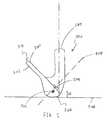
- FIG. 1shows an exemplary wedge 100 in accordance with a prior art wedges wherein the location of the center of gravity (CG) 102 is at a distance d 1 away from the ground 106 .
- distance d 1denotes the location of the CG 102 of wedge 100 being a significant distance away from the ground 106 .
- Distance d 1as shown in this exemplary prior art embodiment may generally be greater than 20 mm; however prior art wedges could have distance d 1 be 21 mm, 22 mm, 23 mm, or any CG 102 location distance that is relatively high within a wedge without departing from exemplary prior art wedge 100 .
- CG 102 locationthat is so high above ground 106 may generally be undesirable as it does not maximize the efficiency of energy transfer between the wedge type golf club head 100 and a golf ball.
- maximizing the CG locationwill also allow for increased performance characteristics such as increased ball speed and increased launch angle that correlates into increased trajectory, increased accuracy, and increased control. Increased ball speed will yield increased shot distance. If an increased spin is desired while keeping shot distance constant, the wedge loft will have to be increased, a characteristic which will mitigate the ballspeed increase while adding even more backspin to the ball, yielding even more overall stopping power or accuracy.
- U.S. Pat. No. 5,547,426 to Wooddiscloses a golf club head using progressively sized heads having slots of selected depths in the back of the golf club head. These golf club heads may have a progressive top edge thickness so that all top edge appear to have the same width in use, but it makes no attempt to utilize and adjust this variation in topline thickness to improve the moment of inertia of the golf club head.
- a golf clubthat is capable of improving the backspin characteristics without the need to either adjust the grooves or provide surface treatment to the wedge type club face. More specifically, there is a need in the field for a wedge type golf club that is capable of optimizing the performance characteristics of a golf shot such as backspin, ball speed, and launch angle by utilizing strategically placed CG locations within the wedge type golf club.
- the CG optimized wedge type golf club headthat has improved performance characteristics may then be used in conjunction with a wedge type golf club head with various grooves or surface treatments to further optimize the backspin characteristics of a wedge type golf club head.
- a wedge type golf club headcomprising of a hosel and a body attached to the hosel, creating a loft angle.
- the bodyis further comprising of a hitting surface and a rear portion wherein the hitting surface defines a neutral axis perpendicular to the hitting surface passing through an impact point on the hitting surface.
- the wedge type golf club headalso comprises of a sole at the bottom of the body at least partially resting on a ground connecting the hitting surface and the rear portion, wherein the loft angle is greater than about 45 degrees and wherein a center of gravity of the wedge type golf club head is located behind the hitting surface substantially along the neutral axis.
- a wedge type golf club headcomprising of a hosel and a body attached to the hosel creating a loft angle, wherein the body comprises of a hitting surface and a rear portion.
- the wedge type golf club headalso comprises of a sole at a bottom of the body at least partially resting on a ground connecting the hitting surface and the rear portion, wherein the loft angle is greater than about 45 degrees, wherein the sole further comprises of a weighted portion, and wherein a density of the weighted portion is greater than a density of the remainder of the wedge type golf club head.
- a wedge type golf club headcomprising of a hosel and a body attached to the hosel, creating a loft angle.
- the bodyis further comprising of a hitting surface and a rear portion wherein the hitting surface defines a neutral axis perpendicular to the hitting surface passing through an impact point on the hitting surface.
- the wedge type golf club headalso comprises of a sole at the bottom of the body at least partially resting on a ground connecting the hitting surface and the rear portion, wherein the loft angle is greater than about 45 degrees, and wherein the center of gravity of the wedge type golf club head is located within a parabolic region of the wedge type golf club head that is bisected by the neutral axis.
- the parabolic regionis further comprised of a vertex located at the impact point of the hitting surface and the open direction of the parabolic region is pointed towards the rear portion of the body of the wedge type golf club head.
- a wedge type golf club headcomprising of a hosel and a body attached to the hosel, creating a loft angle.
- the bodyis further comprising of a hitting surface and a rear portion wherein the hitting surface defines a neutral axis perpendicular to the hitting surface passing through an impact point on the hitting surface.
- the wedge type golf club headalso comprises of a sole at the bottom of the body at least partially resting on a ground connecting the hitting surface and the rear portion, wherein the loft angle is greater than about 45 degrees and wherein the wedge type golf club head has a Performance Ratio of greater than about 530,000 rpm*mph.
- a wedge type golf club headthat needs to have an added loft in order to mitigate the ballspeed increase produced by the lowered CG in the current wedge type golf club head. This will add additional backspin and keep the overall wedge shot distance constant; which is a desirable trait among players with relatively high swing speeds to club distances in the set doesn't overlap one another.
- FIG. 1shows a side view of a prior art wedge type golf club head
- FIG. 2shows a side view of a wedge type golf club head in accordance with an exemplary embodiment of the present invention
- FIG. 3shows a side view of a wedge type golf club head in accordance with an alternative embodiment of the present invention
- FIG. 4shows a side view of a wedge type golf club head in accordance with a further alternative embodiment of the present invention
- FIG. 5shows a side view of a wedge type golf club head in accordance with a further alternative embodiment of the present invention
- FIG. 6shows a side view of a wedge type golf club head in accordance with the current invention wherein the range of the center of gravity CG location is shown;
- FIG. 7shows a side view of an embodiment of the present invention showing the sole portion being made out of a weighted material
- FIG. 8shows a side view of a further alternative embodiment of the present invention showing the sole portion being partially made out of a weighted material
- FIG. 9shows a side view of a further alternative embodiment of the present invention showing a hosel with reduced length
- FIG. 10shows a frontal view of an alternative embodiment of the present invention showing a hitting surface containing grooves
- FIG. 11shows multiple cross-sectional views of groove configurations in accordance with the present invention.
- FIG. 12shows a cross-sectional view of a further alternative embodiment of the present invention showing a different sole profile
- FIG. 13shows a graphical representation of flight conditions of a golf ball after being struck by various wedge type golf club heads
- FIG. 14shows a perspective view of a golf club head in accordance with a further alternative embodiment of the present invention.
- FIG. 15shows a cross-sectional view of the golf club head shown in FIG. 14 ;
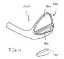
- FIG. 16shows a perspective view of a golf club head in accordance with a further alternative embodiment of the present invention.
- FIG. 17shows a perspective view of the golf club head shown in FIG. 16 ;
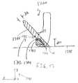
- FIG. 18shows a perspective view of a golf club head in accordance with a further alternative embodiment of the present invention.
- FIG. 19shows a cross-sectional view of the golf club head shown in FIG. 18 ;
- FIG. 20shows a perspective view of a golf club head in accordance with a further alternative embodiment of the present invention.
- FIG. 21shows a perspective view of a golf club head in accordance with a further alternative embodiment of the present invention.
- FIG. 22shows a cross-sectional view of a golf club head in accordance with a further alternative embodiment of the present invention.
- FIG. 2shows a side view of a wedge type golf club head 200 in accordance with an exemplary embodiment of the present invention having a specific center of gravity (CG) 202 location substantially along a neutral axis 208 .
- Wedge type golf club head 200may contain a hosel 209 and a body 211 being attached to the hosel 209 .
- the body 211may be further comprised of a hitting surface 201 and a rear portion 203 connected by a sole 205 portion at the bottom of the wedge type golf club head 200 .
- the sole 205generally has at least a portion of the sole 205 resting on the ground 206 at an angle formed by the sole 205 profile of the wedge type golf club head 200 when the golf club head is placed at address.
- the body 211and more particularly the hitting surface 211 , may be connected to the hosel at a loft angle ⁇ to create a lofted wedge type golf club head 200 .
- the wedge type golf club head 200as shown in the current exemplary embodiment, may have a neutral axis 208 that is perpendicular to the hitting surface 201 , while passing through an impact point 204 on the hitting surface 201 .
- the neutral axis 208may generally be used to help determine the location of a center of gravity (CG) 202 of the wedge type golf club head 200 , wherein the CG 202 location may generally be provided substantially along the neutral axis 208 behind the hitting surface 201 .
- FIG. 2shows the CG 202 being generally at a distance d 2 from the ground 206 in accordance with the present invention.
- Neutral axis 208may generally be an arbitrary line that is ninety degrees and perpendicular to the hitting surface 201 . In addition to being perpendicular to the hitting surface 201 , this neutral axis 208 may also generally pass through the hitting surface 201 at an impact point 204 in accordance with the present invention.
- the neutral axis 208generally determines the path of travel of a golf ball after impacting the wedge type golf club head 200 , and the neutral axis is further defined by the CG 202 location of the wedge type golf club head as the neutral axis 208 also passes through the CG 202 location.
- the wedge type golf club head 200may generally have a CG 202 location significantly lower than that of a prior art wedge type golf club head 100 . (See FIG. 1 ). To put it in another way, the distance d 2 , as shown in FIG. 2 may generally be lesser than the distance d 1 as shown in FIG. 1 . More specifically, wedge type golf club head 200 , as shown in the current exemplary embodiment, has the CG 202 location substantially along the neutral axis 208 instead of at an arbitrary location substantially above the neutral axis shown in FIG. 1 . Even more specifically, FIG. 2 shows that CG 202 may be located directly on the neutral axis 208 and behind the hitting surface 201 and closer to the average impact point for most golfers with a wedge type golf club.
- Having a CG 202 location directly on the neutral axis 208may generally help improve the performance characteristics of a wedge type golf club head 200 by improving energy transfer efficiency and generate more momentum along the impact direction. This improved energy transfer generates more momentum and may directly improve the backspin, the ball speed, and the launch angle of a golf ball that is struck by the wedge type golf club head 200 irrespective of the grooves on the hitting surface 201 of the wedge type golf club head 200 . It should be noted that significant improvements in the performance characteristics may be achieved just by having the CG 202 substantially along the neutral axis 208 and perfect alignment is not necessary. To achieve the significantly improved performance characteristic, the CG 202 location may be any location behind hitting face 201 and preferably at a location substantially along the neutral axis 208 in accordance with an embodiment of the present invention.
- Impact point 204may generally depict the point where a golf ball will come into contact with the wedge type golf club head 200 . To put in another way, impact point may generally be the location where most golfers will hit a golf ball when utilizing a wedge type golf club head.
- Impact point 204may generally be 10 mm to 20 mm from ground 206 ; however, impact point 204 may be more preferably 12 mm to 18 mm from ground 206 or even more preferably from 14 mm to 16 mm from ground 206 , and most preferably 15 mm from ground 206 all without departing from the scope and content of the present invention.
- the impact point 204may help define the upper limit of the CG 202 location that is a distance d 2 away from ground 206 .
- Distance d 2as shown in the current exemplary embodiment may generally be less than 20 mm from ground 206 , however, CG 202 location may more preferably be less than 18 mm from ground 206 or even more preferably less than 16 mm from ground 206 , and most preferably less than 15 mm from ground 206 all without departing from the scope and content of the present invention.
- Loft angle ⁇may generally be directed towards a higher lofted club such as a wedge type golf club head 200 .
- Wedge type golf club head 200may generally have a loft angle ⁇ greater than 45 degrees; however loft angle ⁇ may be less then 45 degrees, or even exactly at 45 degrees all without departing from the scope and content of the present invention so long as the wedge type golf club head 200 could benefit from the enhanced performance that is achievable from the optimized CG 202 location associated with a wedge type golf club head 200 .
- FIG. 3shows an alternative embodiment of the present invention wherein wedge type golf club head 300 , despite also having its CG 302 location substantially along the neutral axis 308 , may have a distance d 3 from the ground 306 that is significantly less than distance d 2 .
- wedge type golf club headmay also have significantly improved performance characteristics such as backspin, ball speed, and launch angle because CG 302 is located directly on the neutral axis 308 .
- Distance d 3may also generally be lower than the impact point 304 , and may generally be less than 20 mm from ground 206 , however, CG 302 location may more preferably be less than 18 mm from ground 306 or even more preferably less than 16 mm from ground 306 , and most preferably less than 15 mm from ground 306 all without departing from the scope and content of the present invention.
- Wedge type golf club head 300due to the CG 302 location, may generally improved energy transfer that generate more momentum may directly improve the backspin, the ball speed, and the launch angle of a golf ball
- FIG. 4shows an even further alternative embodiment of the present invention wherein the wedge type golf club head 400 has a CG 402 location that is substantially along the neutral axis 408 , but not directly on the neutral axis 408 .
- the CG 402may have a location that is slightly above the neutral axis 408 , at a distance d 4 away from ground 406 , while still remaining substantially along the neutral axis 208 .
- CG 402 locationalthough not directly on the neutral axis 408 , is still capable of increasing the performance characteristics that generate more momentum and may directly improve the backspin, the ball speed, and the launch angle of a golf ball especially when compared to a prior art wedge 100 , with its CG 102 location at a much higher location. (Shown in FIG. 1 ).
- FIG. 5shows an even further alternative embodiment of the present invention wherein the wedge type golf club head 500 has a CG 502 location that is substantially along the neutral axis 508 , but also not directly on the neutral axis 508 .
- the CG 502may have a location that is slightly below the neutral axis 508 , at a distance d 5 away from ground 506 .
- CG 502 locationalthough not directly on the neutral axis 508 , is still capable of increasing the performance characteristics that generates more momentum which may directly improve the backspin, the ball speed, and the launch angle of a golf ball especially when compared to a prior art wedge 100 , with its CG 102 location at a much higher location. (Shown in FIG. 1 )
- the CGmay be located at various locations within wedge type golf club head, so long as it is substantially along the neutral axis, all in accordance with the scope and content of the present invention.
- FIG. 6may generally characterize the boundaries of the potential CG location within a wedge type golf club head 600 that further clarifies the “substantially along” terminology in accordance with the present invention.
- FIG. 6may show a wedge type golf club head 600 highlighting a parabolic region 620 that defines the boundaries of the potential CG location of a wedge type golf club head 600 in accordance with an exemplary embodiment of the present invention.
- Parabolic region 620may have its vertex located at the impact point 604 and the parabolic region 620 may generally be bisected by the neutral axis 608 defining its location within the wedge type golf club head 600 .
- Parabolic region 620may generally have an open direction 624 directed towards the rear portion 603 of the body 611 while being slightly slanted towards the sole 605 .
- Parabolic region 620may generally define the boundaries for the location of a CG within wedge type golf club head 600 , as the area encompassed by the parabolic region 620 may generally be considered to be “substantially along” the neutral axis 608 without departing from the scope and content of the present invention.
- FIG. 6may so show a distance d 6 , depicting the upper limit of the height of a potential CG location in accordance with the present invention.
- D 6as shown in the current exemplary embodiment may generally be the same height as impact point 604 , which may generally be 10 mm to 20 mm from ground 606 ; however, impact point 604 may be more preferably 12 mm to 18 mm from ground 606 or even more preferably from 14 mm to 16 mm from ground 606 , and most preferably 15 mm from ground 606 .
- the size of the parabolic region 620may generally determine the CG locations that may be substantially along the neutral axis 608 . More specifically, parabolic region 620 , may generally define a region that will ensure that the CG location be within 7 mm of neutral axis 608 ; more preferably no greater than 5 mm; and most preferably no greater than 3 mm all without departing from the scope and content of the present invention.
- the perimeter of the parabolic region 620may generally depict the region that will encompass the CG locations that will help achieve higher backspin, higher ball speed, and higher launch angle of a golf ball in accordance with the exemplary embodiment of the present invention.
- the parabolic region 620 as shown in FIG. 6may generally allow the CG to be located within a region that will improve performance to accommodate for different swing conditions generally associated with a golf swing. In order to optimize the swing conditions, it may generally be desirable to have the CG location be substantially along the neutral axis 608 , which is based on the impact location 604 . However, because different swings may generally create a different neutral axis 608 the optimal CG location will often vary with different swing characteristics. Because of the above mentioned swing variation, which can sometimes occur intentionally when a player de-lofts a club, the parabolic region 620 that defines the boundaries of the CG location will ensure the wedge type golf club head 600 will achieve optimal performance irrespective of the individual swings.
- FIG. 7may serve to show the physical composition of a wedge type golf club head 700 that can be used to achieve a lower CG 702 location in accordance with the exemplary embodiments of the present invention.
- wedge type golf club head 700may generally have a sole 705 that is further comprising of a weighted portion 732 ; wherein the weighted portion 732 may be comprised of a material that is denser than that of the remainder of the wedge type golf club head 700 .
- the increased density of the weighted portion 732may generally be used to lower the CG 702 of the wedge type golf club 700 to a location that is significantly lower than that of a prior art wedge 100 . (Shown in FIG. 1 )
- Weighted portion 732may generally be comprised of a second material having a relatively high density such as tungsten; however, numerous other materials such as tungsten nickel, lead, copper, iridium, or any other material with a high density may all be used without departing from the scope and content of the present invention.
- the remainder of the wedge type golf club head 700inversely, may generally be comprised of a standard material that has a lower density than that of the weighted portion 732 .
- Wedge type golf club head 700may generally be comprised of steel, however, numerous other materials such as aluminum, iron, copper, titanium, or even plastic so long as it has a density lower than that of the weighted portion 732 all without departing from the scope and content of the present invention.
- weighted portion 732may have a density of about 19300 kg/cubic meters when it is comprised of a material such as tungsten.
- the remainder of the wedge type golf club head 700may have a density of about 7800 kg/cubic meters when it is comprised of a material such as steel.
- This relationship of the density between the weighted portion 732 and the remainder of the wedge type golf club head 700may generally create a weight ratio that is greater than 2.0, more preferably greater than 2.25, and most preferably greater than 2.5; wherein the weight ratio is defined by the density of the weighted portion 732 over density of the remainder of the wedge type golf club head 700 .
- Weighted portion 732may replace the entire sole 705 of the wedge type golf club head 700 to create a lower CG 702 location; however, weighted portion 732 may only partially replace the sole 705 to achieve the desirable optimal CG 702 location without departing from the scope and content of the present invention.
- Wedge type golf club head 700due to the improved CG 702 location that results from the weighted portion 732 may generally have a lower CG 702 location that improves energy transfer to generate more momentum that improves the backspin, the ball speed, and the launch angle of a golf ball based on the weighted portion 732 .
- FIG. 8shows a wedge type golf club head 800 in accordance with a further alternative embodiment of the present invention wherein the weighted portion 832 only partially replaces the sole 805 to achieve the lower CG 802 location.
- FIG. 8shows a weighted portion 832 resembling the shape of a cylindrical rod passing through the sole 805 of the wedge type golf club head 800 in order to achieve the desirable low CG 802 location.
- Weighted portion 832although shown in the current exemplary embodiment as a cylindrical rod, may also be in various other shapes such as a rectangle, a triangular, a octagon, or any other shape that is capable of partially replacing the sole 805 with a material that is of a higher density all without departing from the scope and content of the present invention.
- a chambermay be created in the sole 805 of the golf club head 800 to receive the weighted portion 832 .
- FIG. 9shows another wedge type golf club head 900 in accordance with an even further alternative embodiment of the present invention wherein the hosel 909 has been shortened to help lower the CG 902 location within the wedge type golf club head 900 .
- Shortening the hosel 909removes weight that may generally be located high and away from the sole 905 of the club head, thus allowing the CG 909 to be lowered without the need of a weighted portion.
- the current inventioncould use a shortened hosel 909 in combination with a weighted portion in the sole to further lower the CG 909 of a wedge type golf club head 900 .
- FIG. 10shows a front view of a wedge type golf club head 1000 in accordance with a further exemplary embodiment of the present invention showing a hosel 1009 and a plurality of grooves 1040 on the hitting surface 1001 of the wedge type golf club head 1000 .
- Plurality of grooves 1040may generally be of various shape and sizes and made utilizing various processes as shown in more detail in FIG. 11 without departing from the scope and content of the present invention.
- FIG. 11shows a cross-sectional view of the various embodiments that may be used for the plurality of grooves 1040 .
- Plurality of grooves 1040may be V-shaped as shown by groove 1141 , U-shaped as shown by groove 1142 , square shaped as shown by groove 1143 , hybrid shaped as shown by groove 1145 , or any other groove shape that is capable of improving the coefficient of friction of the wedge type golf club.
- the various groove configurations shown by groove 1141 , groove 1142 , groove 1143 , and groove 1145may be constructed out of various method such as spin milled, stamped, forged, or any other manufacturing process capable of producing the grooves to help the performance characteristics.
- FIG. 12shows a cross-sectional view of a wedge type golf club head 1200 taken along cross-sectional line A-A′ in FIG. 10 to show a further alternative embodiment of the present invention.
- Wedge type golf club head 1200as shown in the current alternative embodiment utilizes a partially hollow rear portion 1203 forming a cavity 1252 that may further contain a weighted portion 1253 , and covered by a lid 1251 .
- This cavity 1252 portionwhich takes away weight from the wedge type golf club head 1200 , may serve to help eliminate weight in the rear portion 1203 of the wedge type golf club head 1200 to help lower the CG 1202 location closer to ground 1206 .
- the weighted portion 1253may help further lower the CG 1202 location closer to ground 1206 .
- the lowered location of CG 1202may help better align the CG 1202 with the neutral axis 1208 , which in turn helps achieve the enhanced performance characteristics such as improve trajectory, accuracy, and control that results from greater backspin.
- Wedge type golf club head 1200due to the improved CG 1202 location, may generally improve energy transfer to generate more momentum that directly improves the backspin, the ball speed, and the launch angle of a golf ball.
- FIGS. 7 , 8 , 9 , and 12all show various methodology that may be used to utilize a weighted portion at the sole of a wedge type golf club head to lower the CG location lower than those of a traditional type wedge type golf club head 100 in order to improve the performance characteristics. More specifically, FIGS. 7 , 8 , 9 , and 12 all lower the CG to a location substantially along the neutral axis within the parabolic region 620 (see FIG. 6 ) in an attempt to improve the backspin and performance characteristics of a wedge type golf club head. It should be noted that FIGS. 7 , 8 , 9 , and 12 only show exemplary methodology that may be used to lower the CG location, and various combinations of the methodology used in FIGS.
- FIGS. 7 , 8 , 9 , and 12or even other methodology not disclosed in FIGS. 7 , 8 , 9 , and 12 may all be used so long as it shifts the CG location within the parabolic region 620 (see FIG. 6 ) without departing from the scope and content of the present invention.
- a wedge type golf club head in accordance with the present inventionperforms so well beyond the actual loft that it is labeled with and measured at, the labeling of the loft angle may need to be adjusted to maintain the same performance numbers previously associated with various wedge type golf club heads.
- a 55 degree wedge in accordance with the current exemplary inventioncould very easily achieve performance numbers traditionally associated with a prior art 54 degree wedge without the optimized CG location.
- FIG. 13shows a graphical representation of a simulated trajectory for a stock 54 degree wedge in accordance with prior art wedges, a stock 55 degree wedge in accordance with a prior art wedge, and a CG modified 55 degree wedge in accordance with the current invention.
- Flight path 1302may generally represent a flight trajectory of a stock 54 degree wedge in accordance with the prior art wedge.
- Flight path 1304as shown in FIG. 13 , may generally represent a flight trajectory of a stock 55 degree wedge in accordance with a prior art wedge.
- flight path 1306as shown in FIG. 13 , may generally represent a flight trajectory of a CG modified 55 degree wedge in accordance with the current invention.
- FIG. 13may demonstrate through various flight paths that a wedge in accordance with the present invention may be able to achieve increased performance characteristics such as improved backspin, increased ball speed, and increased launch angle similar to those having a lower loft without departing from the scope and content of the present invention.
- a wedge type golf club head in accordance with the present inventionmay generally have performance features that are a significant improvement over prior art wedges. Although it may generally be desirable to increase the distance of a golf shot, this improved distance gain in the wedge type golf club head in accordance with the present invention may not be desirable, as accuracy and distance control are more important in a wedge type golf shot. Hence, in order to maintain the same distance, a wedge type golf club head in accordance with the present invention may need to have additional loft to achieve the same distance. This wedge type golf club head with an increased loft may generally be capable of achieving the same distance as a wedge that has a baseline loft value, but do so with an improved trajectory that yields maximum distance control.
- Improved trajectoryas achieved by a wedge type golf club head in accordance with the present invention, will have a higher launch with more spin yielding a steeper angle of descent allowing more predictability upon landing.
- “Drop and stop”may generally be a special term of art used by golfers to describe this increased predictability upon landing. This improved predictability is important in a wedge type golf shot, as it is generally a wedge type club is chosen for its accuracy in attacking the pin.
- FIG. 13shows that a CG optimized wedge in accordance with the present invention may generally achieve a flight path similar to a prior art wedge that is one degree less lofted; a CG optimized wedge in accordance with the present invention may be able to achieve flight path characteristic similar to a prior wedge that is two degrees less, three degrees less, or any number of degrees less all without departing from the scope and content of the present invention.
- wedge type golf club head 200in accordance with the present invention is shown having the CG 202 located substantially along the neutral axis 208 that may generally help improve the performance characteristics of the wedge type golf club head 200 ; particularly when compared to a prior art wedge type golf club head 100 .
- wedge type golf club head 200may have an improvement in a Performance Ratio of the wedge type golf club head that is greater than 15,000 rpm*mph, more preferably greater than 20,000 rpm*mph, and most preferably greater than 21,000 rpm*mph.
- Performance Ratioas defined in the current invention may generally be defined by equation (1) below.
- Performance ⁇ ⁇ Ratio( Launch ⁇ ⁇ Angle ) * ( Ball ⁇ ⁇ Speed ) * ( Backspin ) Loft ( 1 )
- a prior art wedge type golf club head 100may have a launch angle of about 27.1 degrees, a ball speed of about 86.9 mph, a backspin rate of about 12138 rpm, and a loft of about 54 degrees; yielding a Performance Ratio of approximately 529,349 rpm*mph.
- Wedge type golf club head 200in accordance with an exemplary embodiment of the present invention, may generally have a launch angle of about 27.4 degrees, a ball speed of about 88.2 mph, a backspin rate of about 12330 rpm, and a loft of about 54 degrees; yielding a Performance Ratio of approximately 551,808 rpm*mph.
- the change in Performance Ratio from a prior art wedge type golf club head 100 to wedge type golf club head 200may be approximately 22,459 rpm*mph signifying an increased of performance characteristic without departing from the scope and content of the present invention.
- FIG. 14 of the accompanying drawingsshows a perspective view of a golf club head 1400 in accordance with a further alternative embodiment of the present invention. More specifically, golf club head 1400 shown in FIG. 14 may have two different hollow chambers at the rear portion 1403 of the golf club head 1400 providing a different way to adjust the CG of the golf club head 1400 . Even more specifically, the rear portion 1403 of the golf club head 1400 may have an upper chamber 1462 near the upper segment of the golf club head 1400 and a lower chamber 1464 at the bottom segment of the golf club head 1400 . The upper chamber 1462 reduces unnecessary weight from the top of golf club head 1400 , allowing CG of the golf club head to be lowered. The hollow lower chamber 1464 , on the other hand, may generally be filled in with a denser second material to create a weighted portion 1432 that serves to further lower the CG of the golf club head 1400 .
- FIG. 15 of the accompanying drawingsshows a cross-sectional view of the golf club head 1400 shown in FIG. 14 , taken across the middle of the golf club head 1400 .
- the cross-sectional view of the golf club head 1500 shown in FIG. 15allows the geometry of the backing portion 1503 to be shown more clearly in conjunction with the location of the CG 1502 .
- the upper chamber 1562may be hollow while the lower chamber 1564 may be filled with a denser second material to create a weighted portion 1532 to lower the CG 1502 of this golf club head.
- the CG 1502 locationmay generally be at a distance d 15 away from the ground 1506 .
- Distance d 15may generally be greater than about 16 mm and less than about 20 mm, more preferably greater than about 17 mm and less than about 19 mm, most preferably be about 18 mm.
- the weighted portion 1532may take on a different shape or size if the upper chamber 1562 and the lower chamber 1564 take on a different size to further adjust the CG 1502 of the golf club head 1500 without departing from the scope and content of the present invention.
- FIG. 16 of the accompanying drawingsshows a perspective view of a golf club head 1600 in accordance with a further alternative embodiment of the present invention. More specifically, golf club head 1600 may have a thickened upper portion 1666 instead of an upper chamber to help raise the CG of the golf club head 1600 .
- the lower chamber 1664may or may not be filled with a secondary material that is denser than the remainder of the golf club head. When the lower chamber 1664 is filled with a denser secondary material, the denser secondary material helps bring the CG location lower. Alternatively, when the lower chamber 1664 is left hollow, the thickened upper portion 1666 helps raise the CG location of the golf club head 1600 .
- FIG. 17 of the accompanying drawingsshows a cross-sectional view of the golf club head 1600 shown in FIG. 16 , taken across the middle of the golf club head 1600 .
- the cross-sectional view of the golf club head 1700 shown in FIG. 17allows the geometry of the backing portion 1703 to be shown more clearly in conjunction with the location of the CG 1702 .
- the thickened upper portion 1766 of the golf club head 1700 shown in FIG. 17may generally have a first thickness d 18 of greater than about 4.8 mm and less than about 7.1 mm, more preferably greater than about 5.33 mm and less than about 6.6 mm, most preferably about 5.84 mm.
- This thickened upper portionmay generally refer to the thickest portion of the golf club head 1700 that is substantially near the top portion of the golf club head 1700 .
- the cross-sectional view of golf club head 1700shows a CG 1702 location that results when the lower chamber 1764 is filled with a secondary material that has a higher density to create a weighted portion 1732 . It should be noted that if the lower chamber 1764 is left hollow and unfilled, the CG 1702 location may generally be significantly higher. In addition to the above, FIG.
- d 16 of the thinned portion 1735 of the golf club head 17also shows a second thickness d 16 of the thinned portion 1735 of the golf club head 17 , wherein d 16 may generally be less than about 6.5 mm, more preferably less than about 6.0 mm, and most preferably less than about 5.8 mm.
- the thickened upper portion 1766may improve the performance of the golf club head 1700 by improving the stability of the golf club head 1700 as it impacts a golf ball.
- MOIMoment of Inertia
- FIG. 17 of the accompanying drawingsshows a coordinate system 1701 , depicting the y-axis running in a substantially vertical direction, a z-axis running in a horizontal and front to back direction, and a x-axis running in a direction that is stems substantially in a heel to toe direction.
- the improved stability of the golf club head 1700 discussed heremay generally relate to the MOI number about the x-axis of the golf club head 1700 to prevent the golf club head from twisting when the golf club strikes a golf ball at different heights.
- the MOI of the golf club head 1700 about the x-directionmay generally be greater than about 120 kg*mm 2 , more preferably greater than about 125 kg*mm 2 , and most preferably greater than about 129 kg*mm 2 .
- this improved MOIwill also improve the performance of the golf club head by preventing a golf ball from sliding up the face of the golf club head 1700 during impact.
- wedge type golf club headmay generally have a higher loft angle ⁇ , a golf ball that contacts the hitting surface of the golf club head 1700 will be more likely to slide up the face of the golf club head 1700 during impact.
- Having a golf club head 1700 with a higher moment of inertia along the x-axiswill allow the golf club head 1700 to remain steady during impact with a golf ball even at different impact heights, minimizing any movement of the golf club head 1700 despite this higher loft angle ⁇ .
- first thickness d 18 of the thickened upper portion 1766may be one of the more important factors that affect the MOI of a golf club head 1700 along the x-axis
- exact first thickness d 18 of the thickened upper portion 1766may need to be defined relative to the loft ⁇ of the golf club head 1700 .
- a “Topline Thickness Ratio”may be defined as shown below by equation (2) below:
- Topline ⁇ ⁇ Thickness ⁇ ⁇ RatioLoft ⁇ ⁇ ( ⁇ ) ⁇ ⁇ of ⁇ ⁇ Golf ⁇ ⁇ Club ⁇ ⁇ Head First ⁇ ⁇ Thickness ⁇ ⁇ ( d ⁇ ⁇ 18 ) ⁇ ⁇ of ⁇ ⁇ Golf ⁇ ⁇ Club ⁇ ⁇ Head ( 2 )
- “Topline Thickness Ratio”, as demonstrated by the current exemplary embodiment of the present invention,may generally be greater than about 6.0 degrees/mm and less than about 9.0 degrees/mm, more preferably greater than about 7.0 degrees/mm and less than about 9.0 degrees/mm, and most preferably greater than about 8.0 degrees/mm and less than about 9.0 degrees/mm.
- the Topline Thickness Ratio of the current inventive golf club head compared to a prior art golf club headcan be found in Table 1 below.
- Table 1also shows the first thickness d 18 getting progressively thicker as the loft ⁇ of the golf club head 1700 increases. This progressive increase in the first thickness d 18 of the thickened upper portion 1766 is important to the performance of the golf club head 1700 because the higher lofted golf club heads would generally require a thicker upper portion 1766 to provide more stability.
- table 1 abovealso shows the second thickness d 16 of the thinned portion 1735 of the golf club head 1700 .
- Second thickness d 16may be used to calculate a thickness difference of the rear portion of the golf club head, which provides an alternative methodology to quantify the increasing thickness d 16 as it relates to the remainder of the golf club head 1700 .
- a golf club head 1700 in accordance with the current exemplary embodiment of the present inventionmay generally have a thickness difference of greater than about 0.4 mm, more preferably greater than about 1.0 mm, and most preferably greater than about 1.5 mm. This thickness difference can then be used to calculate a “Thickness Difference Ratio”, which provides an alternative way to capture the performance enhancements of the golf club head 1700 , defined by equation (3) below:
- Thickness ⁇ ⁇ Difference ⁇ ⁇ RatioLoft ⁇ ⁇ ( ⁇ ) ⁇ ⁇ of ⁇ ⁇ Golf ⁇ ⁇ Club ⁇ ⁇ Head Thickness ⁇ ⁇ Difference ( 2 ) Thickness Difference Ratio, as it can be seen from above, provides a relationship between the loft of the golf club head 1700 and the thickness difference.
- the golf club head 1700 in accordance with the exemplary embodiment of the present inventionmay generally have a Thickness Difference Ratio of greater than 25 degrees/mm, more preferably greater than 27.5 degrees/mm, and most preferably greater than 30 degrees/mm.
- FIG. 18 of the accompanying drawingsshows a perspective view of a golf club head 1800 in accordance with a further alternative embodiment of the present invention. More specifically, golf club head 1800 may have different geometry for the thickened upper portion 1866 near the top of the backing portion 1803 of the golf club head 1800 . In addition to the thickened upper portion 1866 , the golf club head 1800 may also have a lower chamber 1864 at the bottom of the backing portion 1803 of the golf club head 1800 . Finally, golf club head 1800 may also have a channel 1868 near the center of the backing portion 1803 of the golf club head 1800 between the thickened upper portion 1866 and the lower chamber 1864 . The channel 1868 shown in FIG. 18 may generally serve the purpose of accentuating the CG fluctuations due to the thickened upper portion 1866 and the lower chamber 1864 as it removes material from the center of the golf club head 1800 .
- FIG. 19 of the accompanying drawingsshows a cross-sectional view of the golf club head 1800 shown in FIG. 18 , taken across the middle of the golf club head 1800 .
- the cross-sectional view of the golf club head 1900 shown in FIG. 19allows the geometry of the backing portion 1903 to be shown more clearly.
- the lower chamber 1964may be hollow without departing from the scope and content of the present invention. Because the lower chamber 1964 is not filled with a denser material, the CG 1902 location of the golf club head 1900 may be at a distance d 19 that is significantly further away from the ground 1906 .
- Distance d 19 in this exemplary embodiment of the present inventionmay be greater than about 18 mm and less than about 22 mm, more preferably greater than 19 mm and less than about 21 mm, more preferably about 21 mm all without departing from the scope and content of the present invention.
- FIG. 20 of the accompanying drawingsshows a perspective view of a golf club head 2000 in accordance with a further alternative embodiment of the present invention wherein the backing portion 2003 of the golf club head 2000 may contain an oversized upper chamber 2062 that allows multiple inserts to be inserted into the upper chamber 2062 .
- the multiple insertsmay be comprised of a bottom insert 2072 , a central insert 2074 , and a top insert 2076 .
- the bottom insert 2072may be comprised out of a material having a higher density such as tungsten while the central insert 2074 and the top insert 2076 may be comprised out of a material or materials having a lower density in order to create a golf club head 2000 with a lower center of gravity.
- top insert 2076may be comprised out of a material having a higher density while the central insert 2074 and the bottom insert 2072 may be comprised out of a material having a lower density to create a golf club head 2000 with a higher density in order to create a golf club head 2000 with a higher center of gravity.
- central insert 2074may be comprised out of a material having a higher density such as tungsten while the bottom insert 2072 and the top insert 2076 may be comprised out of a material or materials having a lower density in order to create a golf club head 2000 with more traditional center of gravity of location.
- One advantage of the golf club head 2000 shown in FIG. 20is that such a golf club head allows its CG location to be changed easily by altering the different materials used to create the inserts.
- the higher density material discussed abovemay refer to tungsten, numerous other materials such as tungsten nickel, lead, copper, iridium, or any other material with a high density may all be used without departing from the scope and content of the present invention.
- Lower density material mentioned abovemay generally be made out of materials such as 8620 steel, however numerous other materials such as aluminum, iron, copper, titanium, or even plastic may be used so long as it has a density lower than that of the denser material all without departing from the scope and content of the present invention.
- the present embodimentshows three inserts in order to offer an ability to adjust the CG of the golf club head 2000 , numerous other number combinations of inserts may be used without departing from the scope and content of the present invention. More specifically, the golf club head 2000 may have two inserts, four inserts, five inserts, or any number of inserts that can fit within the upper chamber 2062 all without departing from the scope and content of the present invention.
- FIG. 21 of the accompanying drawingsshows a perspective view of a golf club head 2100 in accordance with a further alternative embodiment of the present invention wherein the backing portion 2103 of the golf club head 2100 may contain multiple chambers to help adjust the CG of the golf club head 2100 . More specifically, golf club head 2100 may have an upper chamber 2162 , a middle chamber 2163 , and a lower chamber 2164 to provide a method of adjusting the CG of the golf club head 2100 . Similar to the discussion above, different inserts being comprised out of a different material having different density to adjust the CG of the golf club head to change the performance characteristics of the golf club head 2100 . Although FIG. 21 shows a golf club head 2100 with three distinct weight chambers, numerous other number of chambers may be used to alter the CG of the golf club head 2100 all without departing from the scope and content of the present invention.
- FIG. 22shows a cross-sectional view of a golf club head 2200 in accordance with a further alternative embodiment of the present invention. More specifically, golf club head 2200 shown here may have a thickened topline portion 2266 and a thinned portion 2235 . It should be noted that in this current exemplary embodiment of the present invention, the thickened topline portion 2266 may have a thickness of d 18 and the thinned portion may have a thickness of d 16 like previously discussed in FIG. 17 . Thickness d 18 may generally refer to the thickest area near the topline portion of the golf club head 2200 and thickness d 16 may generally refer to the thinnest area near the central portion of the golf club head 2200 .
Landscapes
- Health & Medical Sciences (AREA)
- General Health & Medical Sciences (AREA)
- Physical Education & Sports Medicine (AREA)
- Golf Clubs (AREA)
Abstract
Description
“Topline Thickness Ratio”, as demonstrated by the current exemplary embodiment of the present invention, may generally be greater than about 6.0 degrees/mm and less than about 9.0 degrees/mm, more preferably greater than about 7.0 degrees/mm and less than about 9.0 degrees/mm, and most preferably greater than about 8.0 degrees/mm and less than about 9.0 degrees/mm. The Topline Thickness Ratio of the current inventive golf club head compared to a prior art golf club head can be found in Table 1 below.
| TABLE 1 | |||
| Inventive Golf Club Head | Prior Art Golf Club Head #1 | ||
| First | Second | Thickness | “Topline | “Topline | ||
| Thickness | Thickness | Difference | Thickness | Topline | Thickness | |
| (d18) - | (d16) - | (d18/d16) - | Ratio”- | Thickness - | Ratio” | |
| Loft | (mm) | (mm) | (mm) | (degrees/mm) | (mm) | (degrees/mm) |
| 46 | 5.60 | 5.20 | 0.40 | 8.214 | 5.20 | 8.846 |
| 48 | 5.60 | 5.20 | 0.40 | 8.571 | 5.20 | 9.231 |
| 50 | 6.10 | 5.33 | 0.77 | 8.197 | 5.33 | 9.381 |
| 52 | 6.10 | 5.33 | 0.77 | 8.525 | 5.33 | 9.756 |
| 54 | 6.48 | 5.50 | 0.98 | 8.333 | 5.50 | 9.818 |
| 56 | 6.48 | 5.50 | 0.98 | 8.642 | 5.50 | 10.182 |
| 58 | 7.06 | 5.70 | 1.36 | 8.215 | 5.70 | 10.175 |
| 60 | 7.06 | 5.70 | 1.36 | 8.499 | 5.70 | 10.526 |
| 62 | 7.32 | 5.59 | 1.73 | 8.470 | 5.59 | 11.091 |
| 64 | 7.32 | 5.59 | 1.73 | 8.743 | 5.59 | 11.449 |
Thickness Difference Ratio, as it can be seen from above, provides a relationship between the loft of the
Claims (17)
Priority Applications (3)
| Application Number | Priority Date | Filing Date | Title |
|---|---|---|---|
| US14/071,343US9211450B2 (en) | 2009-05-29 | 2013-11-04 | Wedge type golf club head |
| US14/318,781US9713751B2 (en) | 2009-05-29 | 2014-06-30 | Wedge type golf club head |
| US15/130,719US9821202B2 (en) | 2009-05-29 | 2016-04-15 | Wedge type golf club head |
Applications Claiming Priority (4)
| Application Number | Priority Date | Filing Date | Title |
|---|---|---|---|
| US12/474,316US8187120B2 (en) | 2009-05-29 | 2009-05-29 | Wedge type golf club head |
| US12/832,488US8491414B2 (en) | 2009-05-29 | 2010-07-08 | Wedge type golf club head |
| US12/957,562US8579729B2 (en) | 2009-05-29 | 2010-12-01 | Wedge type golf club head |
| US14/071,343US9211450B2 (en) | 2009-05-29 | 2013-11-04 | Wedge type golf club head |
Related Parent Applications (1)
| Application Number | Title | Priority Date | Filing Date |
|---|---|---|---|
| US12/957,562ContinuationUS8579729B2 (en) | 2009-05-29 | 2010-12-01 | Wedge type golf club head |
Related Child Applications (1)
| Application Number | Title | Priority Date | Filing Date |
|---|---|---|---|
| US14/318,781Continuation-In-PartUS9713751B2 (en) | 2009-05-29 | 2014-06-30 | Wedge type golf club head |
Publications (2)
| Publication Number | Publication Date |
|---|---|
| US20140066227A1 US20140066227A1 (en) | 2014-03-06 |
| US9211450B2true US9211450B2 (en) | 2015-12-15 |
Family
ID=46064865
Family Applications (2)
| Application Number | Title | Priority Date | Filing Date |
|---|---|---|---|
| US12/957,562Active2030-05-29US8579729B2 (en) | 2009-05-29 | 2010-12-01 | Wedge type golf club head |
| US14/071,343Active2029-11-14US9211450B2 (en) | 2009-05-29 | 2013-11-04 | Wedge type golf club head |
Family Applications Before (1)
| Application Number | Title | Priority Date | Filing Date |
|---|---|---|---|
| US12/957,562Active2030-05-29US8579729B2 (en) | 2009-05-29 | 2010-12-01 | Wedge type golf club head |
Country Status (1)
| Country | Link |
|---|---|
| US (2) | US8579729B2 (en) |
Cited By (2)
| Publication number | Priority date | Publication date | Assignee | Title |
|---|---|---|---|---|
| US20180280768A1 (en)* | 2011-11-28 | 2018-10-04 | Acushnet Company | Golf club head and method of manufacture |
| US11065513B2 (en) | 2011-11-28 | 2021-07-20 | Acushnet Company | Set of golf club heads and method of manufacture |
Families Citing this family (10)
| Publication number | Priority date | Publication date | Assignee | Title |
|---|---|---|---|---|
| US8579729B2 (en)* | 2009-05-29 | 2013-11-12 | Acushnet Company | Wedge type golf club head |
| US9713751B2 (en)* | 2009-05-29 | 2017-07-25 | Acushnet Company | Wedge type golf club head |
| US9205311B2 (en)* | 2013-03-04 | 2015-12-08 | Karsten Manufacturing Corporation | Club head with sole mass element and related method |
| US9415280B2 (en) | 2013-07-26 | 2016-08-16 | Karsten Manufacturing Corporation | Golf club heads with sole weights and related methods |
| US9427633B2 (en) | 2013-12-31 | 2016-08-30 | Nike Inc. | Iron-type golf clubs and golf club heads |
| JP6086898B2 (en) | 2013-12-31 | 2017-03-01 | ナイキ イノベイト セー. フェー. | Golf club and golf club head |
| US9295887B2 (en)* | 2013-12-31 | 2016-03-29 | Nike, Inc | Iron-type golf clubs and golf club heads |
| USD773574S1 (en) | 2015-02-12 | 2016-12-06 | Acushnet Company | Wedge golf club set |
| USD762792S1 (en) | 2015-02-12 | 2016-08-02 | Acushnet Company | Wedge golf club head |
| USD829837S1 (en) | 2017-03-01 | 2018-10-02 | Acushnet Company | Wedge golf club |
Citations (139)
| Publication number | Priority date | Publication date | Assignee | Title |
|---|---|---|---|---|
| US645942A (en) | 1899-11-29 | 1900-03-27 | Spalding & Bros Ag | Golf-club. |
| US1453503A (en) | 1921-08-08 | 1923-05-01 | Thomas J Holmes | Golf club |
| US1642462A (en) | 1925-10-20 | 1927-09-13 | Spalding & Bros Ag | Golf club |
| US1835718A (en) | 1931-03-20 | 1931-12-08 | Julian W Morton | Golf club |
| US2007377A (en) | 1932-12-29 | 1935-07-09 | L A Young Company | Golf club |
| US2254528A (en) | 1939-09-21 | 1941-09-02 | William V Hoare | Golf club |
| US2332342A (en) | 1940-03-08 | 1943-10-19 | Milton B Reach | Golf club |
| US2460445A (en) | 1948-04-19 | 1949-02-01 | Charles W Bigler | Adjustable weight for golf club heads |
| US2784969A (en) | 1953-10-02 | 1957-03-12 | Spalding A G & Bros Inc | Golf clubs |
| US3419275A (en) | 1965-10-23 | 1968-12-31 | Joseph R. Winkleman | Putter head with magnetic weight adjusting means |
| US3606327A (en) | 1969-01-28 | 1971-09-20 | Joseph M Gorman | Golf club weight control capsule |
| US3655188A (en) | 1969-07-09 | 1972-04-11 | Karsten Solheim | Correlated golf club set |
| US3751035A (en) | 1971-07-02 | 1973-08-07 | J Lockwood | Set of golf irons |
| US3845960A (en) | 1973-06-11 | 1974-11-05 | S Thompson | Weight-balanced golfing iron |
| US3961796A (en) | 1973-06-11 | 1976-06-08 | Thompson Stanley C | Golfing iron head with downwardly tapered keel |
| US3979122A (en) | 1975-06-13 | 1976-09-07 | Belmont Peter A | Adjustably-weighted golf irons and processes |
| US4145052A (en) | 1977-05-03 | 1979-03-20 | Janssen Robert L | Golfing iron with weight adjustment |
| US4147349A (en) | 1975-12-18 | 1979-04-03 | Fabrique Nationale Herstal S.A. | Set of golf clubs |
| US4180269A (en) | 1978-05-08 | 1979-12-25 | Thompson Stanley C | Weight adjustment of golfing iron heads |
| US4211416A (en) | 1978-11-22 | 1980-07-08 | Swanson Arthur P | Golf club |
| US4247105A (en) | 1975-12-18 | 1981-01-27 | Fabrique National Herstal S.A. | Set of golf clubs |
| US4322083A (en) | 1978-10-26 | 1982-03-30 | Shintomi Golf Co., Ltd. | Golf club head |
| US4326326A (en) | 1980-07-09 | 1982-04-27 | The Merion Corporation | Method of making metal golf club head |
| US4607846A (en) | 1986-05-03 | 1986-08-26 | Perkins Sonnie J | Golf club heads with adjustable weighting |
| US4802672A (en) | 1987-06-24 | 1989-02-07 | Macgregor Golf Company | Set of golf irons |
| US4836550A (en) | 1987-01-26 | 1989-06-06 | Maruman Golf Co., Ltd. | Club head for an iron-type golf club |
| US4869507A (en) | 1986-06-16 | 1989-09-26 | Players Golf, Inc. | Golf club |
| US4941666A (en) | 1986-08-27 | 1990-07-17 | Noriyuki Suganuma | Golf club, set of golf clubs, and method of producing the same |
| US5011151A (en) | 1989-09-06 | 1991-04-30 | Antonious A J | Weight distribution for golf club head |
| US5013041A (en) | 1990-01-22 | 1991-05-07 | Cipa Manufacturing Corporation | Golf driver with variable weighting for changing center of gravity |
| US5050879A (en) | 1990-01-22 | 1991-09-24 | Cipa Manufacturing Corporation | Golf driver with variable weighting for changing center of gravity |
| US5120062A (en) | 1990-07-26 | 1992-06-09 | Wilson Sporting Goods Co. | Golf club head with high toe and low heel weighting |
| USD327109S (en) | 1989-01-27 | 1992-06-16 | Wilson Sporting Goods Co. | Golf club head |
| USD329481S (en) | 1989-05-30 | 1992-09-15 | Hunt James R | Iron golf club head |
| US5199707A (en) | 1992-06-01 | 1993-04-06 | Knox James G | Golf club |
| US5312106A (en) | 1992-10-14 | 1994-05-17 | Cook Don R | Composite weighted golf club heads |
| US5326105A (en) | 1993-05-20 | 1994-07-05 | Fenton Golf, Inc. | Sea plane sole for a golf club |
| US5366222A (en) | 1993-11-23 | 1994-11-22 | Lee Steven P | Golf club head having a weight distributing system |
| US5385348A (en) | 1993-11-15 | 1995-01-31 | Wargo; Elmer | Method and system for providing custom designed golf clubs having replaceable swing weight inserts |
| US5421577A (en) | 1993-04-15 | 1995-06-06 | Kobayashi; Kenji | Metallic golf clubhead |
| US5429353A (en) | 1993-07-30 | 1995-07-04 | Acushnet Company | Golf club irons and method of manufacture of iron sets |
| US5437088A (en) | 1993-01-19 | 1995-08-01 | Igarashi; Lawrence Y. | Method of making a golf club that provides enhanced backspin and reduced sidespin |
| US5439223A (en) | 1992-04-02 | 1995-08-08 | Kobayashi; Kenji | Golf club head |
| USD362887S (en) | 1994-09-20 | 1995-10-03 | Ben Hogan Company | Golf club head |
| USD364435S (en) | 1994-10-14 | 1995-11-21 | Plop Golf Company | Golf club head |
| USD368753S (en) | 1994-09-20 | 1996-04-09 | Ben Hogan Company | Golf club head |
| US5547426A (en) | 1995-12-18 | 1996-08-20 | Plop Golf Company | Progressive golf club having a diagonally balanced slot back |
| JPH08257173A (en) | 1995-03-28 | 1996-10-08 | Daiwa Seiko Inc | Golf club set |
| US5629475A (en) | 1995-06-01 | 1997-05-13 | Chastonay; Herman A. | Method of relocating the center of percussion on an assembled golf club to either the center of the club head face or some other club head face location |
| US5643106A (en) | 1995-04-24 | 1997-07-01 | Baird; William | Golf club head |
| US5655976A (en) | 1995-12-18 | 1997-08-12 | Rife; Guerin | Golf club head with improved weight configuration |
| US5688189A (en) | 1995-11-03 | 1997-11-18 | Bland; Bertram Alvin | Golf putter |
| US5716292A (en) | 1996-07-24 | 1998-02-10 | Huang; Hui Ming | Golf club head |
| US5728010A (en) | 1997-02-19 | 1998-03-17 | Hsu; Tsai-Fu | Golf club head improved in its center of gravity |
| US5749794A (en) | 1993-05-31 | 1998-05-12 | Kabushiki Kaisha Endo Seisakusho | Golf club head |
| US5776009A (en) | 1997-04-29 | 1998-07-07 | Mcatee; Joseph P. | Momentum generating golf club |
| JPH10192459A (en) | 1997-01-14 | 1998-07-28 | Sumitomo Heavy Ind Ltd | Golf club head |
| US5804272A (en) | 1997-03-14 | 1998-09-08 | Schrader; Gunter | Backspin sticker |
| US5803830A (en) | 1994-08-01 | 1998-09-08 | Austin; Michael Hoke | Optimum dynamic impact golf clubs |
| JPH10244025A (en) | 1997-03-03 | 1998-09-14 | Sumitomo Rubber Ind Ltd | Iron head |
| JPH10258143A (en) | 1997-03-18 | 1998-09-29 | Nkk Corp | Golf club head |
| JPH10277187A (en) | 1997-04-07 | 1998-10-20 | Shoe Takahashi | Golf club head which allows fine adjustment of weight distribution |
| JPH10295861A (en) | 1997-04-28 | 1998-11-10 | Yonetsukusu Kk | Iron club for golf and iron club set formed by using the same |
| JPH1133145A (en) | 1997-07-16 | 1999-02-09 | Sumitomo Rubber Ind Ltd | Wood golf club head |
| US5890971A (en) | 1995-08-21 | 1999-04-06 | The Yokohama Rubber Co., Ltd. | Golf club set |
| JPH11146934A (en) | 1997-11-17 | 1999-06-02 | Yamaha Corp | Club head for golf |
| JPH11155985A (en) | 1997-12-01 | 1999-06-15 | Kanetaka Yamamoto | Golf club |
| US5913735A (en) | 1997-11-14 | 1999-06-22 | Royal Collection Incorporated | Metallic golf club head having a weight and method of manufacturing the same |
| US6015354A (en) | 1998-03-05 | 2000-01-18 | Ahn; Stephen C. | Golf club with adjustable total weight, center of gravity and balance |
| US6045455A (en) | 1997-01-22 | 2000-04-04 | Callaway Golf Company | Inertially tailored golf club heads |
| JP2000116823A (en) | 1998-10-15 | 2000-04-25 | Bridgestone Sports Co Ltd | Golf club head |
| JP2000167089A (en) | 1998-12-03 | 2000-06-20 | Bridgestone Sports Co Ltd | Golf club head |
| US6086485A (en) | 1997-12-18 | 2000-07-11 | Jiro Hamada | Iron golf club heads, iron golf clubs and golf club evaluating method |
| JP2000300701A (en) | 1999-04-23 | 2000-10-31 | Bridgestone Sports Co Ltd | Wood type golf club head |
| US6179726B1 (en) | 1998-09-25 | 2001-01-30 | Ryobi Limited | Iron golf club set |
| JP2001037929A (en) | 1999-07-01 | 2001-02-13 | Karsten Mfg Corp | Iron golf club head with weight control member |
| EP1082976A1 (en) | 1999-04-05 | 2001-03-14 | Mizuno Corporation | Golf club head, iron golf club head, wood golf club head, and golf club set |
| JP2001104520A (en) | 1999-10-05 | 2001-04-17 | Bridgestone Sports Co Ltd | Golf club set |
| US6224494B1 (en) | 1999-01-04 | 2001-05-01 | Bernard J. Patsky | Golf club with multiple sweet spot markings and methods and tools for locating same |
| US6290607B1 (en) | 1999-04-05 | 2001-09-18 | Acushnet Company | Set of golf clubs |
| US6290609B1 (en) | 1999-03-11 | 2001-09-18 | K.K. Endo Seisakusho | Iron golf club |
| JP2001259094A (en) | 2000-02-25 | 2001-09-25 | Carbite Inc | Polar balance type golf club head |
| JP2001314535A (en) | 2000-05-08 | 2001-11-13 | Mizuno Corp | Hollow iron head |
| JP2002119627A (en) | 2000-10-16 | 2002-04-23 | Yokohama Rubber Co Ltd:The | Golf club head |
| JP2002143356A (en) | 2000-11-07 | 2002-05-21 | Mizuno Corp | Iron golf club head and iron golf club set |
| JP2002253712A (en) | 2001-03-02 | 2002-09-10 | Endo Mfg Co Ltd | Golf club |
| JP2003047678A (en) | 2001-08-03 | 2003-02-18 | Bridgestone Sports Co Ltd | Golf club head |
| US6530846B1 (en) | 2000-09-06 | 2003-03-11 | Acushnet Company | Golf club set |
| US6533679B1 (en) | 2000-04-06 | 2003-03-18 | Acushnet Company | Hollow golf club |
| JP2003102875A (en) | 2001-09-28 | 2003-04-08 | Sumitomo Rubber Ind Ltd | Iron type golf set |
| US6554722B2 (en) | 1999-06-11 | 2003-04-29 | Callaway Golf Company | Golf club head |
| JP2003135632A (en) | 2001-11-07 | 2003-05-13 | Sumitomo Rubber Ind Ltd | Iron-type golf club head |
| JP2003169870A (en) | 2001-12-06 | 2003-06-17 | Mizuno Corp | Iron golf club |
| JP2003180889A (en) | 2001-12-17 | 2003-07-02 | Daiwa Seiko Inc | Golf club head |
| JP2003190340A (en) | 2001-12-28 | 2003-07-08 | Endo Mfg Co Ltd | Golf club |
| JP2003236025A (en) | 2001-04-09 | 2003-08-26 | Mizuno Corp | Wood club head |
| JP2003265653A (en) | 2002-03-14 | 2003-09-24 | Bridgestone Sports Co Ltd | Golf club set |
| JP2003299755A (en) | 2002-04-09 | 2003-10-21 | Sumitomo Rubber Ind Ltd | Iron type golf club head |
| US6641491B1 (en) | 2002-05-01 | 2003-11-04 | Pippo G. Schillaci | Golf sand wedge head |
| US6719642B2 (en) | 2001-10-19 | 2004-04-13 | Taylor Made Golf Company, Inc. | Golf club head |
| JP2004135991A (en) | 2002-10-21 | 2004-05-13 | Daiwa Seiko Inc | Golf club head |
| JP2004141451A (en) | 2002-10-25 | 2004-05-20 | Endo Mfg Co Ltd | Golf club and manufacturing method thereof |
| JP2004159680A (en) | 2002-11-08 | 2004-06-10 | Shigeki Yamamoto | Golf club head |
| US20040127300A1 (en) | 2001-06-25 | 2004-07-01 | Roger Cleveland Golf Company, Inc. | Golf clubhead |
| US6811496B2 (en) | 2000-12-01 | 2004-11-02 | Taylor Made Golf Company, Inc. | Golf club head |
| US6860819B2 (en) | 1999-04-05 | 2005-03-01 | Achushnet Company | Set of golf clubs |
| US6872153B2 (en) | 2003-06-25 | 2005-03-29 | Acushnet Company | Golf club iron |
| JP2005185652A (en) | 2003-12-26 | 2005-07-14 | Pepaaretsuto Kk | Golf club head |
| US6923734B2 (en) | 2003-04-25 | 2005-08-02 | Jas. D. Easton, Inc. | Golf club head with ports and weighted rods for adjusting weight and center of gravity |
| JP2005278757A (en) | 2004-03-29 | 2005-10-13 | Daiwa Seiko Inc | Golf club head |
| JP2005319122A (en) | 2004-05-10 | 2005-11-17 | Fu Sheng Industrial Co Ltd | Iron head of golf club |
| JP2006000139A (en) | 2004-06-15 | 2006-01-05 | Fu Sheng Industrial Co Ltd | Structure of golf club head capable of adjusting vibration absorption |
| US7014568B2 (en) | 2001-11-19 | 2006-03-21 | David Pelz | Golf club |
| JP2006081862A (en) | 2004-09-20 | 2006-03-30 | Fu Sheng Industrial Co Ltd | Combination structure of golf club head and weight |
| JP2006122371A (en) | 2004-10-29 | 2006-05-18 | Daiwa Seiko Inc | Golf club |
| JP2006149478A (en) | 2004-11-25 | 2006-06-15 | Endo Mfg Co Ltd | Golf club |
| JP2006223460A (en) | 2005-02-16 | 2006-08-31 | Yokohama Rubber Co Ltd:The | Golf club head, golf club, and golf club set |
| JP2006223461A (en) | 2005-02-16 | 2006-08-31 | Yokohama Rubber Co Ltd:The | Golf club head, golf club, and golf club set |
| JP2006239154A (en) | 2005-03-03 | 2006-09-14 | Nelson Precision Casting Co Ltd | Adjustment structure of composite material of golf club head |
| US7186187B2 (en) | 2005-04-14 | 2007-03-06 | Acushnet Company | Iron-type golf clubs |
| WO2007044220A1 (en) | 2005-10-06 | 2007-04-19 | The Beta Group Llc. | Golf clubs |
| US7207900B2 (en) | 2004-07-29 | 2007-04-24 | Karsten Manufacturing Corporation | Golf club head weight adjustment member |
| US7294065B2 (en) | 2005-02-04 | 2007-11-13 | Fu Sheng Industrial Co., Ltd. | Weight assembly for golf club head |
| JP2007319687A (en) | 2006-05-31 | 2007-12-13 | Acushnet Co | Muscle back golf club with large moment of inertia and low center of gravity |
| US7338387B2 (en) | 2003-07-28 | 2008-03-04 | Callaway Golf Company | Iron golf club |
| US7396295B1 (en) | 2006-08-24 | 2008-07-08 | Taylor Made Golf Company, Inc. | Golf club head |
| JP2009066417A (en) | 2007-09-13 | 2009-04-02 | Acushnet Co | Golf club |
| US7513835B2 (en) | 2005-11-23 | 2009-04-07 | Peter Angelo Belmont | Golf club heads |
| US20090176596A1 (en) | 2004-11-25 | 2009-07-09 | K. K. Endo Seisakusho | Wedge type golf club including pitching wedge, approach wedge and sand wedge |
| US7575523B2 (en) | 2006-01-10 | 2009-08-18 | Sri Sports Limited | Golf club head |
| US7588502B2 (en) | 2005-12-26 | 2009-09-15 | Sri Sports Limited | Golf club head |
| JP2009261930A (en) | 2008-04-08 | 2009-11-12 | Acushnet Co | Iron golf club |
| US7670236B2 (en) | 2006-12-27 | 2010-03-02 | Bridgestone Sports Co., Ltd. | Club head for iron golf club |
| US7803064B2 (en) | 2004-03-11 | 2010-09-28 | Cobra Golf, Inc. | Golf club head with multiple undercuts |
| US7988564B2 (en) | 2008-12-19 | 2011-08-02 | Karsten Manufacturing Corporation | Golf clubs with progressive tapered face thicknesses |
| US8083610B2 (en) | 2004-07-26 | 2011-12-27 | Sri Sports Limited | Muscle-back, with insert, iron type golf club head |
| US8088023B2 (en) | 2006-10-06 | 2012-01-03 | Bridgestone Sports Co., Ltd. | Iron golf club head |
| US8187120B2 (en) | 2009-05-29 | 2012-05-29 | Acushnet Company | Wedge type golf club head |
| US8579729B2 (en)* | 2009-05-29 | 2013-11-12 | Acushnet Company | Wedge type golf club head |
Family Cites Families (2)
| Publication number | Priority date | Publication date | Assignee | Title |
|---|---|---|---|---|
| JPH0822322B2 (en)* | 1989-04-06 | 1996-03-06 | 株式会社遠藤製作所 | Golf club set |
| JPH09285571A (en)* | 1996-04-19 | 1997-11-04 | Maruman Golf Corp | Iron club set |
- 2010
- 2010-12-01USUS12/957,562patent/US8579729B2/enactiveActive
- 2013
- 2013-11-04USUS14/071,343patent/US9211450B2/enactiveActive
Patent Citations (148)
| Publication number | Priority date | Publication date | Assignee | Title |
|---|---|---|---|---|
| US645942A (en) | 1899-11-29 | 1900-03-27 | Spalding & Bros Ag | Golf-club. |
| US1453503A (en) | 1921-08-08 | 1923-05-01 | Thomas J Holmes | Golf club |
| US1642462A (en) | 1925-10-20 | 1927-09-13 | Spalding & Bros Ag | Golf club |
| US1835718A (en) | 1931-03-20 | 1931-12-08 | Julian W Morton | Golf club |
| US2007377A (en) | 1932-12-29 | 1935-07-09 | L A Young Company | Golf club |
| US2254528A (en) | 1939-09-21 | 1941-09-02 | William V Hoare | Golf club |
| US2332342A (en) | 1940-03-08 | 1943-10-19 | Milton B Reach | Golf club |
| US2460445A (en) | 1948-04-19 | 1949-02-01 | Charles W Bigler | Adjustable weight for golf club heads |
| US2784969A (en) | 1953-10-02 | 1957-03-12 | Spalding A G & Bros Inc | Golf clubs |
| US3419275A (en) | 1965-10-23 | 1968-12-31 | Joseph R. Winkleman | Putter head with magnetic weight adjusting means |
| US3606327A (en) | 1969-01-28 | 1971-09-20 | Joseph M Gorman | Golf club weight control capsule |
| US3655188A (en) | 1969-07-09 | 1972-04-11 | Karsten Solheim | Correlated golf club set |
| US3751035A (en) | 1971-07-02 | 1973-08-07 | J Lockwood | Set of golf irons |
| US3845960A (en) | 1973-06-11 | 1974-11-05 | S Thompson | Weight-balanced golfing iron |
| US3961796A (en) | 1973-06-11 | 1976-06-08 | Thompson Stanley C | Golfing iron head with downwardly tapered keel |
| US3979122A (en) | 1975-06-13 | 1976-09-07 | Belmont Peter A | Adjustably-weighted golf irons and processes |
| US4147349A (en) | 1975-12-18 | 1979-04-03 | Fabrique Nationale Herstal S.A. | Set of golf clubs |
| US4247105A (en) | 1975-12-18 | 1981-01-27 | Fabrique National Herstal S.A. | Set of golf clubs |
| US4145052A (en) | 1977-05-03 | 1979-03-20 | Janssen Robert L | Golfing iron with weight adjustment |
| US4180269A (en) | 1978-05-08 | 1979-12-25 | Thompson Stanley C | Weight adjustment of golfing iron heads |
| US4322083A (en) | 1978-10-26 | 1982-03-30 | Shintomi Golf Co., Ltd. | Golf club head |
| US4211416A (en) | 1978-11-22 | 1980-07-08 | Swanson Arthur P | Golf club |
| US4326326A (en) | 1980-07-09 | 1982-04-27 | The Merion Corporation | Method of making metal golf club head |
| US4607846A (en) | 1986-05-03 | 1986-08-26 | Perkins Sonnie J | Golf club heads with adjustable weighting |
| US4869507A (en) | 1986-06-16 | 1989-09-26 | Players Golf, Inc. | Golf club |
| US4941666A (en) | 1986-08-27 | 1990-07-17 | Noriyuki Suganuma | Golf club, set of golf clubs, and method of producing the same |
| US4836550A (en) | 1987-01-26 | 1989-06-06 | Maruman Golf Co., Ltd. | Club head for an iron-type golf club |
| US4802672A (en) | 1987-06-24 | 1989-02-07 | Macgregor Golf Company | Set of golf irons |
| USD327109S (en) | 1989-01-27 | 1992-06-16 | Wilson Sporting Goods Co. | Golf club head |
| USD329481S (en) | 1989-05-30 | 1992-09-15 | Hunt James R | Iron golf club head |
| US5011151A (en) | 1989-09-06 | 1991-04-30 | Antonious A J | Weight distribution for golf club head |
| US5013041A (en) | 1990-01-22 | 1991-05-07 | Cipa Manufacturing Corporation | Golf driver with variable weighting for changing center of gravity |
| US5050879A (en) | 1990-01-22 | 1991-09-24 | Cipa Manufacturing Corporation | Golf driver with variable weighting for changing center of gravity |
| US5120062A (en) | 1990-07-26 | 1992-06-09 | Wilson Sporting Goods Co. | Golf club head with high toe and low heel weighting |
| US5439223A (en) | 1992-04-02 | 1995-08-08 | Kobayashi; Kenji | Golf club head |
| US5199707A (en) | 1992-06-01 | 1993-04-06 | Knox James G | Golf club |
| US5312106A (en) | 1992-10-14 | 1994-05-17 | Cook Don R | Composite weighted golf club heads |
| US5437088A (en) | 1993-01-19 | 1995-08-01 | Igarashi; Lawrence Y. | Method of making a golf club that provides enhanced backspin and reduced sidespin |
| US5421577A (en) | 1993-04-15 | 1995-06-06 | Kobayashi; Kenji | Metallic golf clubhead |
| US5326105A (en) | 1993-05-20 | 1994-07-05 | Fenton Golf, Inc. | Sea plane sole for a golf club |
| US5749794A (en) | 1993-05-31 | 1998-05-12 | Kabushiki Kaisha Endo Seisakusho | Golf club head |
| US5429353A (en) | 1993-07-30 | 1995-07-04 | Acushnet Company | Golf club irons and method of manufacture of iron sets |
| US5385348A (en) | 1993-11-15 | 1995-01-31 | Wargo; Elmer | Method and system for providing custom designed golf clubs having replaceable swing weight inserts |
| US5366222A (en) | 1993-11-23 | 1994-11-22 | Lee Steven P | Golf club head having a weight distributing system |
| US5803830A (en) | 1994-08-01 | 1998-09-08 | Austin; Michael Hoke | Optimum dynamic impact golf clubs |
| USD362887S (en) | 1994-09-20 | 1995-10-03 | Ben Hogan Company | Golf club head |
| USD368753S (en) | 1994-09-20 | 1996-04-09 | Ben Hogan Company | Golf club head |
| USD364435S (en) | 1994-10-14 | 1995-11-21 | Plop Golf Company | Golf club head |
| JPH08257173A (en) | 1995-03-28 | 1996-10-08 | Daiwa Seiko Inc | Golf club set |
| US5643106A (en) | 1995-04-24 | 1997-07-01 | Baird; William | Golf club head |
| US5629475A (en) | 1995-06-01 | 1997-05-13 | Chastonay; Herman A. | Method of relocating the center of percussion on an assembled golf club to either the center of the club head face or some other club head face location |
| US5890971A (en) | 1995-08-21 | 1999-04-06 | The Yokohama Rubber Co., Ltd. | Golf club set |
| US5688189A (en) | 1995-11-03 | 1997-11-18 | Bland; Bertram Alvin | Golf putter |
| US5655976A (en) | 1995-12-18 | 1997-08-12 | Rife; Guerin | Golf club head with improved weight configuration |
| US5547426A (en) | 1995-12-18 | 1996-08-20 | Plop Golf Company | Progressive golf club having a diagonally balanced slot back |
| US5716292A (en) | 1996-07-24 | 1998-02-10 | Huang; Hui Ming | Golf club head |
| JPH10192459A (en) | 1997-01-14 | 1998-07-28 | Sumitomo Heavy Ind Ltd | Golf club head |
| US6045455A (en) | 1997-01-22 | 2000-04-04 | Callaway Golf Company | Inertially tailored golf club heads |
| US5728010A (en) | 1997-02-19 | 1998-03-17 | Hsu; Tsai-Fu | Golf club head improved in its center of gravity |
| JPH10244025A (en) | 1997-03-03 | 1998-09-14 | Sumitomo Rubber Ind Ltd | Iron head |
| US5804272A (en) | 1997-03-14 | 1998-09-08 | Schrader; Gunter | Backspin sticker |
| JPH10258143A (en) | 1997-03-18 | 1998-09-29 | Nkk Corp | Golf club head |
| JPH10277187A (en) | 1997-04-07 | 1998-10-20 | Shoe Takahashi | Golf club head which allows fine adjustment of weight distribution |
| JPH10295861A (en) | 1997-04-28 | 1998-11-10 | Yonetsukusu Kk | Iron club for golf and iron club set formed by using the same |
| US5776009A (en) | 1997-04-29 | 1998-07-07 | Mcatee; Joseph P. | Momentum generating golf club |
| JPH1133145A (en) | 1997-07-16 | 1999-02-09 | Sumitomo Rubber Ind Ltd | Wood golf club head |
| US5913735A (en) | 1997-11-14 | 1999-06-22 | Royal Collection Incorporated | Metallic golf club head having a weight and method of manufacturing the same |
| JPH11146934A (en) | 1997-11-17 | 1999-06-02 | Yamaha Corp | Club head for golf |
| JPH11155985A (en) | 1997-12-01 | 1999-06-15 | Kanetaka Yamamoto | Golf club |
| US6368232B1 (en) | 1997-12-18 | 2002-04-09 | Jiro Hamada | Iron golf club heads, iron golf clubs and golf club evaluating method |
| US6086485A (en) | 1997-12-18 | 2000-07-11 | Jiro Hamada | Iron golf club heads, iron golf clubs and golf club evaluating method |
| US6344000B1 (en) | 1997-12-18 | 2002-02-05 | Jiro Hamada | Iron golf club heads, iron golf clubs and golf club evaluating method |
| US6015354A (en) | 1998-03-05 | 2000-01-18 | Ahn; Stephen C. | Golf club with adjustable total weight, center of gravity and balance |
| US6179726B1 (en) | 1998-09-25 | 2001-01-30 | Ryobi Limited | Iron golf club set |
| JP2000116823A (en) | 1998-10-15 | 2000-04-25 | Bridgestone Sports Co Ltd | Golf club head |
| JP2000167089A (en) | 1998-12-03 | 2000-06-20 | Bridgestone Sports Co Ltd | Golf club head |
| US6224494B1 (en) | 1999-01-04 | 2001-05-01 | Bernard J. Patsky | Golf club with multiple sweet spot markings and methods and tools for locating same |
| US6290609B1 (en) | 1999-03-11 | 2001-09-18 | K.K. Endo Seisakusho | Iron golf club |
| EP1082976A1 (en) | 1999-04-05 | 2001-03-14 | Mizuno Corporation | Golf club head, iron golf club head, wood golf club head, and golf club set |
| US6860819B2 (en) | 1999-04-05 | 2005-03-01 | Achushnet Company | Set of golf clubs |
| US6290607B1 (en) | 1999-04-05 | 2001-09-18 | Acushnet Company | Set of golf clubs |
| JP2000300701A (en) | 1999-04-23 | 2000-10-31 | Bridgestone Sports Co Ltd | Wood type golf club head |
| US6554722B2 (en) | 1999-06-11 | 2003-04-29 | Callaway Golf Company | Golf club head |
| JP2001037929A (en) | 1999-07-01 | 2001-02-13 | Karsten Mfg Corp | Iron golf club head with weight control member |
| US6206790B1 (en) | 1999-07-01 | 2001-03-27 | Karsten Manufacturing Corporation | Iron type golf club head with weight adjustment member |
| JP2001104520A (en) | 1999-10-05 | 2001-04-17 | Bridgestone Sports Co Ltd | Golf club set |
| JP2001259094A (en) | 2000-02-25 | 2001-09-25 | Carbite Inc | Polar balance type golf club head |
| US6533679B1 (en) | 2000-04-06 | 2003-03-18 | Acushnet Company | Hollow golf club |
| JP2001314535A (en) | 2000-05-08 | 2001-11-13 | Mizuno Corp | Hollow iron head |
| US6530846B1 (en) | 2000-09-06 | 2003-03-11 | Acushnet Company | Golf club set |
| US6679784B2 (en) | 2000-09-06 | 2004-01-20 | Acushnet Company | Golf club set |
| JP2002119627A (en) | 2000-10-16 | 2002-04-23 | Yokohama Rubber Co Ltd:The | Golf club head |
| JP2002143356A (en) | 2000-11-07 | 2002-05-21 | Mizuno Corp | Iron golf club head and iron golf club set |
| US7083530B2 (en) | 2000-12-01 | 2006-08-01 | Taylor Made Golf Company, Inc. | Golf club head |
| US6811496B2 (en) | 2000-12-01 | 2004-11-02 | Taylor Made Golf Company, Inc. | Golf club head |
| JP2002253712A (en) | 2001-03-02 | 2002-09-10 | Endo Mfg Co Ltd | Golf club |
| US6638183B2 (en) | 2001-03-02 | 2003-10-28 | K.K. Endo Seisakusho | Golf club |
| JP2003236025A (en) | 2001-04-09 | 2003-08-26 | Mizuno Corp | Wood club head |
| US20040127300A1 (en) | 2001-06-25 | 2004-07-01 | Roger Cleveland Golf Company, Inc. | Golf clubhead |
| JP2003047678A (en) | 2001-08-03 | 2003-02-18 | Bridgestone Sports Co Ltd | Golf club head |
| JP2003102875A (en) | 2001-09-28 | 2003-04-08 | Sumitomo Rubber Ind Ltd | Iron type golf set |
| US6719642B2 (en) | 2001-10-19 | 2004-04-13 | Taylor Made Golf Company, Inc. | Golf club head |
| JP2003135632A (en) | 2001-11-07 | 2003-05-13 | Sumitomo Rubber Ind Ltd | Iron-type golf club head |
| US7014568B2 (en) | 2001-11-19 | 2006-03-21 | David Pelz | Golf club |
| JP2003169870A (en) | 2001-12-06 | 2003-06-17 | Mizuno Corp | Iron golf club |
| JP2003180889A (en) | 2001-12-17 | 2003-07-02 | Daiwa Seiko Inc | Golf club head |
| JP2003190340A (en) | 2001-12-28 | 2003-07-08 | Endo Mfg Co Ltd | Golf club |
| JP2003265653A (en) | 2002-03-14 | 2003-09-24 | Bridgestone Sports Co Ltd | Golf club set |
| JP2003299755A (en) | 2002-04-09 | 2003-10-21 | Sumitomo Rubber Ind Ltd | Iron type golf club head |
| US6641491B1 (en) | 2002-05-01 | 2003-11-04 | Pippo G. Schillaci | Golf sand wedge head |
| JP2004135991A (en) | 2002-10-21 | 2004-05-13 | Daiwa Seiko Inc | Golf club head |
| US6793591B2 (en) | 2002-10-25 | 2004-09-21 | K. K. Endo Seisakusho | Golf club and method of producing the same |
| JP2004141451A (en) | 2002-10-25 | 2004-05-20 | Endo Mfg Co Ltd | Golf club and manufacturing method thereof |
| JP2004159680A (en) | 2002-11-08 | 2004-06-10 | Shigeki Yamamoto | Golf club head |
| US6923734B2 (en) | 2003-04-25 | 2005-08-02 | Jas. D. Easton, Inc. | Golf club head with ports and weighted rods for adjusting weight and center of gravity |
| US6872153B2 (en) | 2003-06-25 | 2005-03-29 | Acushnet Company | Golf club iron |
| US7338387B2 (en) | 2003-07-28 | 2008-03-04 | Callaway Golf Company | Iron golf club |
| JP2005185652A (en) | 2003-12-26 | 2005-07-14 | Pepaaretsuto Kk | Golf club head |
| US7037213B2 (en) | 2003-12-26 | 2006-05-02 | Peparlet Co. Ltd. | Golf club head |
| US7803064B2 (en) | 2004-03-11 | 2010-09-28 | Cobra Golf, Inc. | Golf club head with multiple undercuts |
| JP2005278757A (en) | 2004-03-29 | 2005-10-13 | Daiwa Seiko Inc | Golf club head |
| JP2005319122A (en) | 2004-05-10 | 2005-11-17 | Fu Sheng Industrial Co Ltd | Iron head of golf club |
| JP2006000139A (en) | 2004-06-15 | 2006-01-05 | Fu Sheng Industrial Co Ltd | Structure of golf club head capable of adjusting vibration absorption |
| US8083610B2 (en) | 2004-07-26 | 2011-12-27 | Sri Sports Limited | Muscle-back, with insert, iron type golf club head |
| US7207900B2 (en) | 2004-07-29 | 2007-04-24 | Karsten Manufacturing Corporation | Golf club head weight adjustment member |
| JP2006081862A (en) | 2004-09-20 | 2006-03-30 | Fu Sheng Industrial Co Ltd | Combination structure of golf club head and weight |
| JP2006122371A (en) | 2004-10-29 | 2006-05-18 | Daiwa Seiko Inc | Golf club |
| JP2006149478A (en) | 2004-11-25 | 2006-06-15 | Endo Mfg Co Ltd | Golf club |
| US20090176596A1 (en) | 2004-11-25 | 2009-07-09 | K. K. Endo Seisakusho | Wedge type golf club including pitching wedge, approach wedge and sand wedge |
| US7294065B2 (en) | 2005-02-04 | 2007-11-13 | Fu Sheng Industrial Co., Ltd. | Weight assembly for golf club head |
| JP2006223461A (en) | 2005-02-16 | 2006-08-31 | Yokohama Rubber Co Ltd:The | Golf club head, golf club, and golf club set |
| JP2006223460A (en) | 2005-02-16 | 2006-08-31 | Yokohama Rubber Co Ltd:The | Golf club head, golf club, and golf club set |
| JP2006239154A (en) | 2005-03-03 | 2006-09-14 | Nelson Precision Casting Co Ltd | Adjustment structure of composite material of golf club head |
| US7186187B2 (en) | 2005-04-14 | 2007-03-06 | Acushnet Company | Iron-type golf clubs |
| WO2007044220A1 (en) | 2005-10-06 | 2007-04-19 | The Beta Group Llc. | Golf clubs |
| US7513835B2 (en) | 2005-11-23 | 2009-04-07 | Peter Angelo Belmont | Golf club heads |
| US7588502B2 (en) | 2005-12-26 | 2009-09-15 | Sri Sports Limited | Golf club head |
| US7575523B2 (en) | 2006-01-10 | 2009-08-18 | Sri Sports Limited | Golf club head |
| JP2007319687A (en) | 2006-05-31 | 2007-12-13 | Acushnet Co | Muscle back golf club with large moment of inertia and low center of gravity |
| US7396295B1 (en) | 2006-08-24 | 2008-07-08 | Taylor Made Golf Company, Inc. | Golf club head |
| US8088023B2 (en) | 2006-10-06 | 2012-01-03 | Bridgestone Sports Co., Ltd. | Iron golf club head |
| US7670236B2 (en) | 2006-12-27 | 2010-03-02 | Bridgestone Sports Co., Ltd. | Club head for iron golf club |
| JP2009066417A (en) | 2007-09-13 | 2009-04-02 | Acushnet Co | Golf club |
| US8257198B2 (en) | 2007-09-13 | 2012-09-04 | Acushnet Company | Iron-type golf club |
| JP2009261930A (en) | 2008-04-08 | 2009-11-12 | Acushnet Co | Iron golf club |
| US7988564B2 (en) | 2008-12-19 | 2011-08-02 | Karsten Manufacturing Corporation | Golf clubs with progressive tapered face thicknesses |
| US8187120B2 (en) | 2009-05-29 | 2012-05-29 | Acushnet Company | Wedge type golf club head |
| US8579729B2 (en)* | 2009-05-29 | 2013-11-12 | Acushnet Company | Wedge type golf club head |
Non-Patent Citations (2)
| Title |
|---|
| Jackson, J., The Modern Guide to Golf Clubmaking,1987, p. 237, Dynacraft Golf Products, Inc., Newark, Ohio, USA. |
| JP H10-244025-Machine Translation. |
Cited By (4)
| Publication number | Priority date | Publication date | Assignee | Title |
|---|---|---|---|---|
| US20180280768A1 (en)* | 2011-11-28 | 2018-10-04 | Acushnet Company | Golf club head and method of manufacture |
| US11065513B2 (en) | 2011-11-28 | 2021-07-20 | Acushnet Company | Set of golf club heads and method of manufacture |
| US11504589B2 (en) | 2011-11-28 | 2022-11-22 | Acushnet Company | Set of golf club heads and method of manufacture |
| US12121783B2 (en) | 2011-11-28 | 2024-10-22 | Acushnet Company | Set of golf club heads and method of manufacture |
Also Published As
| Publication number | Publication date |
|---|---|
| US20140066227A1 (en) | 2014-03-06 |
| US8579729B2 (en) | 2013-11-12 |
| US20120129628A1 (en) | 2012-05-24 |
Similar Documents
| Publication | Publication Date | Title |
|---|---|---|
| US9821202B2 (en) | Wedge type golf club head | |
| US9211450B2 (en) | Wedge type golf club head | |
| US8187120B2 (en) | Wedge type golf club head | |
| US8491414B2 (en) | Wedge type golf club head | |
| US9573028B2 (en) | Golf club with improved performance characteristics | |
| US6991558B2 (en) | Golf club head | |
| US8328658B2 (en) | Golf club with rails | |
| US8641550B2 (en) | Golf club heads | |
| US11697051B2 (en) | Golf club heads with energy storage features | |
| US8187115B2 (en) | Set of constant face center metal woods | |
| US12263384B2 (en) | Golf club heads with energy storage characteristics | |
| US12280301B2 (en) | Golf club heads with a multi-material striking surface | |
| US11666809B2 (en) | Golf club heads with energy storage characteristics | |
| US20240108952A1 (en) | Golf club head | |
| US20100331106A1 (en) | Golf club with improved performance characteristics | |
| US20220362637A1 (en) | Golf club heads with a multi-material striking surface |
Legal Events
| Date | Code | Title | Description |
|---|---|---|---|
| AS | Assignment | Owner name:ACUSHNET COMPANY, MASSACHUSETTS Free format text:ASSIGNMENT OF ASSIGNORS INTEREST;ASSIGNORS:NELSON, RICHARD M.;JOHNSON, GREGORY D.;TASSISTRO, KEVIN;AND OTHERS;SIGNING DATES FROM 20101116 TO 20101123;REEL/FRAME:031540/0288 | |
| AS | Assignment | Owner name:KOREA DEVELOPMENT BANK, NEW YORK BRANCH, NEW YORK Free format text:SECURITY INTEREST;ASSIGNOR:ACUSHNET COMPANY;REEL/FRAME:032607/0744 Effective date:20140310 | |
| STCF | Information on status: patent grant | Free format text:PATENTED CASE | |
| AS | Assignment | Owner name:WELLS FARGO BANK, NATIONAL ASSOCIATION, AS ADMINISTRATIVE AGENT, CALIFORNIA Free format text:SECURITY INTEREST;ASSIGNOR:ACUSHNET COMPANY;REEL/FRAME:039506/0030 Effective date:20160728 Owner name:WELLS FARGO BANK, NATIONAL ASSOCIATION, AS ADMINIS Free format text:SECURITY INTEREST;ASSIGNOR:ACUSHNET COMPANY;REEL/FRAME:039506/0030 Effective date:20160728 | |
| AS | Assignment | Owner name:ACUSHNET COMPANY, MASSACHUSETTS Free format text:RELEASE OF SECURITY INTEREST IN PATENTS PREVIOUSLY RECORDED AT REEL/FRAME (032607/0744);ASSIGNOR:KOREA DEVELOPMENT BANK, NEW YORK BRANCH;REEL/FRAME:039939/0524 Effective date:20160728 | |
| MAFP | Maintenance fee payment | Free format text:PAYMENT OF MAINTENANCE FEE, 4TH YEAR, LARGE ENTITY (ORIGINAL EVENT CODE: M1551); ENTITY STATUS OF PATENT OWNER: LARGE ENTITY Year of fee payment:4 | |
| AS | Assignment | Owner name:JPMORGAN CHASE BANK, N.A., AS SUCCESSOR ADMINISTRATIVE AGENT, ILLINOIS Free format text:ASSIGNMENT OF SECURITY INTEREST IN PATENTS (ASSIGNS 039506-0030);ASSIGNOR:WELLS FARGO BANK, NATIONAL ASSOCIATION, AS RESIGNING ADMINISTRATIVE AGENT;REEL/FRAME:061521/0414 Effective date:20220802 Owner name:JPMORGAN CHASE BANK, N.A., AS ADMINISTRATIVE AGENT, ILLINOIS Free format text:SECURITY INTEREST;ASSIGNOR:ACUSHNET COMPANY;REEL/FRAME:061099/0236 Effective date:20220802 | |
| MAFP | Maintenance fee payment | Free format text:PAYMENT OF MAINTENANCE FEE, 8TH YEAR, LARGE ENTITY (ORIGINAL EVENT CODE: M1552); ENTITY STATUS OF PATENT OWNER: LARGE ENTITY Year of fee payment:8 |