US9211125B2 - Flexible clip applier - Google Patents
Flexible clip applierDownload PDFInfo
- Publication number
- US9211125B2 US9211125B2US12/256,698US25669808AUS9211125B2US 9211125 B2US9211125 B2US 9211125B2US 25669808 AUS25669808 AUS 25669808AUS 9211125 B2US9211125 B2US 9211125B2
- Authority
- US
- United States
- Prior art keywords
- flexible tool
- clip
- jaws
- rails
- shaft
- Prior art date
- Legal status (The legal status is an assumption and is not a legal conclusion. Google has not performed a legal analysis and makes no representation as to the accuracy of the status listed.)
- Active, expires
Links
- 238000000034methodMethods0.000claimsdescription7
- 238000001356surgical procedureMethods0.000claimsdescription6
- 230000007246mechanismEffects0.000description6
- 239000000463materialSubstances0.000description2
- YVHQVYNGHPFVKY-UHFFFAOYSA-NCC1=CCC2=C1CC2Chemical compoundCC1=CCC2=C1CC2YVHQVYNGHPFVKY-UHFFFAOYSA-N0.000description1
- 239000000853adhesiveSubstances0.000description1
- 230000001070adhesive effectEffects0.000description1
- 230000008878couplingEffects0.000description1
- 238000010168coupling processMethods0.000description1
- 238000005859coupling reactionMethods0.000description1
- 238000012978minimally invasive surgical procedureMethods0.000description1
- 238000003466weldingMethods0.000description1
Images


Classifications
- A—HUMAN NECESSITIES
- A61—MEDICAL OR VETERINARY SCIENCE; HYGIENE
- A61B—DIAGNOSIS; SURGERY; IDENTIFICATION
- A61B17/00—Surgical instruments, devices or methods
- A61B17/12—Surgical instruments, devices or methods for ligaturing or otherwise compressing tubular parts of the body, e.g. blood vessels or umbilical cord
- A61B17/128—Surgical instruments, devices or methods for ligaturing or otherwise compressing tubular parts of the body, e.g. blood vessels or umbilical cord for applying or removing clamps or clips
- A61B17/1285—Surgical instruments, devices or methods for ligaturing or otherwise compressing tubular parts of the body, e.g. blood vessels or umbilical cord for applying or removing clamps or clips for minimally invasive surgery
- A—HUMAN NECESSITIES
- A61—MEDICAL OR VETERINARY SCIENCE; HYGIENE
- A61B—DIAGNOSIS; SURGERY; IDENTIFICATION
- A61B17/00—Surgical instruments, devices or methods
- A61B17/00234—Surgical instruments, devices or methods for minimally invasive surgery
- A—HUMAN NECESSITIES
- A61—MEDICAL OR VETERINARY SCIENCE; HYGIENE
- A61B—DIAGNOSIS; SURGERY; IDENTIFICATION
- A61B17/00—Surgical instruments, devices or methods
- A61B17/12—Surgical instruments, devices or methods for ligaturing or otherwise compressing tubular parts of the body, e.g. blood vessels or umbilical cord
- A61B17/122—Clamps or clips, e.g. for the umbilical cord
- A61B17/1227—Spring clips
- A—HUMAN NECESSITIES
- A61—MEDICAL OR VETERINARY SCIENCE; HYGIENE
- A61B—DIAGNOSIS; SURGERY; IDENTIFICATION
- A61B17/00—Surgical instruments, devices or methods
- A61B17/00234—Surgical instruments, devices or methods for minimally invasive surgery
- A61B2017/00292—Surgical instruments, devices or methods for minimally invasive surgery mounted on or guided by flexible, e.g. catheter-like, means
- A—HUMAN NECESSITIES
- A61—MEDICAL OR VETERINARY SCIENCE; HYGIENE
- A61B—DIAGNOSIS; SURGERY; IDENTIFICATION
- A61B17/00—Surgical instruments, devices or methods
- A61B17/28—Surgical forceps
- A61B17/29—Forceps for use in minimally invasive surgery
- A61B2017/2901—Details of shaft
- A61B2017/2905—Details of shaft flexible
Definitions
- the present inventionrelates generally to a flexible clip applier for applying a surgical clip.
- Surgical instrumentshave been developed for use with a variety of endoscopic surgical techniques and procedures.
- clip applier for occlusion and ligation of vesselsare well known.
- Conventional clip applierstypically include an elongated body having a proximal end connected to an actuating mechanism, and a pair of jaws supported at the distal end.
- the jawsinclude a pair of opposing jaw members which are movable with respect to each other.
- the jawsmay be configured to grasp a target area (e.g., a section of body tissue) therebetween.
- a target areae.g., a section of body tissue
- the jawsare moved relative to each other when an operator operates an actuating handle coupled to an actuating mechanism.
- multiple surgical clipsare supported in the elongated body and moved distally, one at a time, into the jaw members in preparation for being applied to a section of tissue.
- conventional clip appliershave a rigid elongated body for receiving surgical clips therein. Therefore, these conventional clip appliers cannot extend through, e.g., an endoscope having an elongated channel that includes at least one curved portion.
- the distal end of the clip applier(e.g., proximate the jaws) may become damaged during assembly, transport, etc.
- a clip applierwhich can be used in a variety of endoscopic procedures including in an endoscope having a elongated channel that includes at least one curved portion. Further, what is also needed is a durable, resilient clip applier which is resistant to damage that may occur to conventional prior art clip appliers having a rigid elongated body and distal end.
- a non-limiting embodiment of the present inventionprovides a clip applier for applying a surgical clip to a target area during a surgical procedure.
- the clip applierincludes a shaft having a proximal end and a distal end.
- the distal end of the shaftincludes a flexible tool having at least two rails connected to each other by at least one jointed connection.
- the at least two railsare configured to rotate about the jointed connection, and a pair of jaws may be provided at a distal end of the flexible tool.
- an actuatormay be provided at the proximal end of the shaft to advance the surgical clip within the flexible tool.
- the at least two railsmay include at least three rails
- the at least one jointed connectionmay include a plurality of jointed connections such that a jointed connection of the plurality of jointed connections connects the at least two rails of the at least three rails.
- the jointed connectionmay include a pin or any other suitable connector which allows relative rotation between the rails.
- the at least two rails and the jointed connectionmay be configured together to allow the distal end of the shaft to bend at a plurality of locations.
- the actuatormay include a hand piece.
- the actuatormay include a flexible (e.g., deformable) wire connected to a pusher and coupled to the hand-piece.
- both the flexible wire and pushermay be actuatable towards the distal end of the shaft such that, upon actuation of the handpiece, the pusher may engage a rear surface of a proximal-most surgical clip so as to advance the surgical clip within the flexible tool and towards the jaws.
- a length of the surgical clipmay be approximately the same as a length of the rails.
- the jawsmay be provided with an inwardly projecting ledge.
- the ledgemay be configured to engage the surgical clip and temporarily expand the surgical clip from a pre-biased closed position to an open position so as to engage (or clamp) a target area.
- the shaftmay include an outer pipe and outer coil.
- the outer pipemay be configured to rotatably support the jaws and the outer coil surrounding the flexible tool.
- a proximal end of the outer pipemay be connected to a distal end of the outer coil.
- a projectionmay be provided at a proximal end of the jaws and a receiving aperture provided at a distal end of a distal-most rail.
- the projectionmay be received within the receiving aperture such that the jaws are pivotably to the distal-most rail.
- the flexible toolmay be detachably connectable to the proximal end of the shaft.
- the shaftmay include an outer pipe and outer coil.
- the outer pipemay be configured to rotatably support the jaws and the outer coil may provide a covering for the flexible tool.
- rotation of at least one of the outer coil, flexible wire and a sheath, press-fitted to a rear end of the flexible toolis configured to rotate the flexible tool.
- the clip appliermay be part of clip applier apparatus.
- the clip applier apparatusmay include at least one surgical clip; a shaft having a proximal end and a distal end, the distal end of the shaft comprising a flexible tool having at least two rails connected to each other by at least one jointed connection, and the at least two rails configured to rotate about the jointed connection.
- a pair of jawsmay be provided at a distal end of the flexible tool
- an actuatormay be provided at the proximal end of the shaft.
- the actuatormay be configured to advance the at least one surgical clip within the flexible tool.
- the clip appliermay include a shaft with a proximal end and a distal end, the distal end of the shaft may have a flexible tool having at least two rails connected to each other by at least one jointed connection, and the at least two rails may be configured to rotate about the jointed connection. Further, the clip applier may also have a pair of jaws at a distal end of the flexible tool. Additionally, the clip applier may include an actuator. In this regard, the method of applying a clip to the target area may include flexing the flexible tool; and actuating the actuator such that a clip is advanced within the flexible tool.
- the clip appliermay be part of a surgical assembly.
- the surgical assemblymay include an endoscope having an elongated channel, and a shaft having a proximal end and a distal end, the distal end of the shaft comprising a flexible tool having at least two rails which are connected to each other by at least one jointed connection. Further, the at least two rails may be configured to pivot about the jointed connection, and at least the flexible tool may be configured to be inserted within the channel of the endoscope.
- a pair jawsmay be provided at a distal end of the flexible tool and an actuator may be provided at the proximal end of the shaft. In this regard, the actuator may be configured to advance a surgical clip within the flexible tool.
- FIGS. 1A and 1BFIG. 1A is a perspective view of a clip applier according to a non-limiting embodiment of the present invention, and FIG. 1B is an enlarged section view;
- FIG. 2is a perspective view of a flexible tool of the clip applier according to a non-limiting embodiment of the present invention
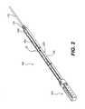
- FIG. 3is a side view of the flexible tool illustrating rails of the flexible tool articulated at connection points;
- FIG. 4Ais a top plan view of the flexible tool
- FIG. 4Bis a cross-sectional view of the flexible tool of FIG. 4 taken along section A—A of FIG. 4A ;
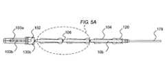
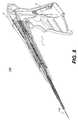
- FIG. 5Ais a detailed view of surgical clips positioned within the rails of the flexible tool
- FIG. 5Bis an exploded view showing the surgical clip, connection point and rails in further detail
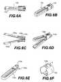
- FIGS. 6A-6Fare perspective views of various opened and closed positions of jaws of the flexible tool of the present invention.
- FIGS. 7A-7Eillustrate the flexible tool performing a surgical procedure for clamping a target area
- FIG. 8is a cross-sectional view of a hand-piece of the clip applier
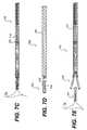
- FIG. 9is a perspective view of an endoscope for performing a minimally invasive surgical procedure.
- FIG. 10is a cross-sectional view of the clip applier of the present invention inserted within an elongated channel of the endoscope.
- FIG. 1shows a flexible tool 100 of a clip applier 300 for applying a surgical clip ( 104 , as shown in, e.g., FIG. 3 ) to a target area during a surgical procedure.
- the clip applier 300may include a shaft 301 having a proximal end 301 a and a distal end 301 b . Further, the distal end 301 b of the shaft 301 may include the flexible tool 100 .
- the flexible tool 100may have at least two rails 108 connected to each other by at least one jointed connection 106 such that the rails 108 are configured to rotate about the jointed connection 106 .
- each rail segmentmay have both an upper side edge 108 U and a lower side edge 108 L extending in a longitudinal direction of the shaft 301 , and wherein opposing rails segments 108 are not connected to each other at the upper side edges 108 U and the lower side edges 108 L.
- jaws 103are provided at a distal end of the flexible tool 100 .
- an actuator Amay be provided at a proximal end 301 a of the shaft 301 .
- the actuator Amay be configured to open and close the jaws 103 (e.g., either directly or through a mechanism which couples an action of the actuator to movement of the jaws) and advance the surgical clip 104 within the flexible tool 100 .
- FIGS. 5A and 5Bshows the flexible tool 100 having the plurality of rails 108 and the jointed connection 106 comprising a plurality of jointed connections (also 106 ). Therefore, it should be appreciated that the plurality of rails 108 may be provided in any number suitable for achieving a desired flexibility of the flexible tool 100 . Additionally, the rails 108 (as well as surgical clips which are configured to be received therein) may also be of a length suitable to achieve the desired flexibility of the flexible tool 100 .
- the jointed connection 106may comprise any suitable connector which would allow the rails 108 to rotate about the connection 106 ; thereby further providing the flexible tool 100 with the desired flexibility.
- the plurality of rails 108 and jointed connections 106are configured to allow the distal end 301 b of the shaft to bend at various locations.
- the jointed connection 106may comprise a pin (also 106 ), a flexible material connecting adjacent rails, or a male/female connection.
- the flexible tool 100may be coupled to an actuator A comprising a hand-piece H having a trigger T for actuating a flexible wire 118 in a forward direction (i.e., towards a distal end of the clip applier).
- the actuator Amay also include a flexible wire 118 connected to a pusher 120 and coupled to the hand-piece H. Therefore, both the flexible wire 118 and pusher 120 may be actuateable towards in a forward direction upon actuation of the handpiece H .
- the pusher 120may be configured to engage a rear surface of a proximal-most surgical clip 104 so as to advance the surgical clip(s) 104 within the flexible tool 100 and in the forward direction towards the jaws 103 .
- the flexible wiremay be connected to a suitable actuating mechanism, e.g. (a piston), which is configured to reciprocate linearly in a backwards and forward (i.e., proximal and distal) direction.
- a suitable actuating mechanisme.g. (a piston)
- depression of a trigger T provided on the hand piece Hmay cause the piston P to be actuated linearly in a forward direction, thereby causing the flexible wire 118 and pusher 120 to be actuateable in the forward direction.
- the pusher 120may be configured to engage a rear surface of a proximal-most surgical clip 104 so as to advance the surgical clip 104 within the flexible tool 100 and towards the jaw members 103 a , 103 b.
- the flexible tool 100may include an outer pipe 102 and an outer coil 101 .
- the outer pipe 102may be configured to rotatably support the jaw members 103 a , 103 b and the outer coil 101 may provide an outer resilient covering of the flexible tool 100 .
- a proximal end of the outer pipe 102may be connected to a distal end of the outer coil 101 by any suitable connection (e.g., by welding or adhesive).
- the outer pipe 102may move in the forward direction so that the jaw members 103 a , 103 b rotate to a closed position (see FIGS. 6A and 6B ), and the outer pipe 102 may move in the rearward direction so that the jaw members 103 a , 103 b rotate towards an opened position (see FIGS. 6C and 6D ).
- the outer pipe 102may be configured to rotatably support the jaw members 103 a , 103 b and the outer coil 101 may comprise the outer covering of the flexible tool 100 .
- a projection 130 amay be provided at a proximal end of the jaws 103 and a receiving aperture provided at a distal end of a distal-most rail 108 .
- the projection 130 amay be received within the receiving aperture 130 b (as shown in FIG. 5A ) thereby rotatably coupling the jaw members 103 a to the distal-most rail 108 .
- the jaws 103may be configured to rotate as the outer pipe 102 reciprocates.
- the outer pipe protrusion 102 a proximate the rear ends of the jaws 103may engage the rear end of jaws 103 ; thereby, causing the jaw members 103 a , 103 b to rotate.
- the pusher 120may be positioned between the rails 108 .
- the pusher 120may be rotated about a longitudinal axis of the shaft 301 by rotating the flexible wire 118 connected to the pusher 120 .
- a sheath 131may be press-fitted (or otherwise fitted) to the rear end of the proximal-most rail 108 , the sheath 131 may rotate concurrently with the rails 108 .
- the pusher 120 , the flexible wire 118 , and the rails 108are all coupled to each other, the flexible tool 100 may be rotated by rotating the outer coil 100 , the flexible wire 118 and/or the sheath 131 .
- a length of the surgical clip 104may be approximately the same as a length of the rails 108 .
- each jawmay comprise an inwardly projecting ledge 109 .
- the ledge 109may be configured to project inwardly from an inner surface of a corresponding jaw member 103 a , 103 b so as to engage the surgical clip 104 and temporarily expand the surgical clip 104 from a pre-biased closed position to an open position in order to clamp the target area (see, FIGS. 7A-7E ).
- the jaws 103may be actuated so as to clamp a target area TA therebetween. Subsequent to clamping the target area TA, the distal-most surgical clip 104 may be advanced such that a front end thereof engages the projecting ledge 109 (e.g., as the front end of the surgical clip 104 is advanced along the projecting ledges), thereby expanding the surgical clip 104 to an opened position from the pre-biased closed position. Further, the surgical clip 104 may return to the pre-biased closed position after the surgical clip 104 advances pass a point where the projecting ledge 109 terminates; whereupon the surgical clip 104 is allowed to return to a pre-biased closed position and clamp the target area TA therebetween. Further, the jaws 103 may be actuated to an opened position so as to release the target area TA, while the surgical clip 104 continues to clamp target area TA.
- the flexible tool 100may be detachably coupled to the proximal end of the shaft 301 a.
- At least one of the outer coil 101 , flexible wire 118 and a sheath 131 , press-fitted to a rear end of the flexible tool 100may be configured to rotate the flexible tool 100 .
- FIGS. 7A-7Eoperation of the clip applier is explained in further detail.
- the clipwhen no force is exerted on the clip 104 , the clip is in a closed position because the clip 104 is pre-biased towards a closed position, much like a bobby pin. Therefore, when the clip 104 engages the rails 109 of the jaws 103 the clip 104 is urged to open so as to prepare to, e.g., engage, receive or clamp tissue positioned between the jaws (see FIG. 7C ).
- the surgical clip 104when the clip 104 is advanced forward to a portion of the jaws 103 which does not include the inwardly projecting ledge 109 (e.g., a position where the inwardly projecting ledge 109 terminates), the surgical clip 104 disengages the ledge 109 , and, as a result, the surgical clip 104 is allowed to return to its pre-biased closed position; thereby clamping the tissue held between the jaws (see FIG. 7E ).
- the jaws 103may be configured to pivot about a support to opened and closed positions.
- the jaws 103may pivot in the closing direction when the outer pipe 102 moves forward and comes in contact with the jaws 103 .
- the outer pipe 102moves in the rearward (or proximal) direction (i.e., opposing the forward, or distal, direction) the jaws may be opened (see FIG. 7E ).
- the outer pipe 102may be provided with the outer pipe protrusion 102 a which is configured to engage at least one of the jaw members 103 a or 103 b .
- the outer pipe protrusion 102 amay come into contact with a proximal end portion of at least one of the jaws 103 (see FIG. 6D ), thereby pivoting the jaw members 103 a , 103 b to an open position.
- a front end of the outer pipe 102when actuated in a forward direction, may engage surfaces of the jaws 103 in order to rotate the jaws to a closed position (see FIG. 6A ).
- the outer pipe 102may be provided with cam surfaces which engage the jaw members 103 a , 103 b in order to open and close the jaws 103 .
- FIGS. 7A-7Eshow a procedure for clamping a target area TA .
- the surgical clip applier 300may approach a target area TA and clamp the target area TA by moving the outer coil 101 and outer pipe 102 forward, thereby closing the jaw members 103 a , 103 b .
- the pusher 120may be actuated in the forward direction in order to advance the surgical clip 104 within the flexible tool 100 .
- the surgical clip 104may be advanced forward to a portion of the jaws 103 which does not include the jaw rails (see FIG. 7D ).
- the surgical clip 104may then disengage the jaw rail 109 , and clamp the target area TA held by the jaw members 103 a , 103 b , since the surgical clip 104 is pre-biased towards its closed position.
- the clip applier 103can be removed from the target area TA, leaving the surgical clip 104 in place ( FIG. 7E ).
- the present inventionallows for the clip applier 300 to have a diameter of about 3 mm to 5 mm and a length of about 1 to 2 meters, i.e., in order to provide a flexible minimally-invasive clip applier, although those of skill in the art would appreciate that the clip applier would have other suitable diameters and lengths.
- the flexible clip applier 300can be inserted into the channel 400 a of an endoscope 400 (see FIG. 9 ) and the flexible tool 100 may include a small cartridge, for example, having three surgical clips (see FIG. 10 ); although any suitable desirable number of surgical clips may be provided within the cartridge.
- the flexible tool(as well as the surgical clip cartridge) may be provided to be detachable and disposable (e.g., as shown in FIG. 2 ).
- FIG. 10illustrates a surgical assembly including an endoscope 400 having an elongated channel 400 a , at least one surgical clip 104 , and a clip applier 300 .
- the clip applier 300may include a shaft 301 having a proximal end 301 a and a distal end 301 b .
- the distal end 301 b of the shaft 301may include a flexible tool 100 having at least two rails 108 which are connected to each other by at least one jointed connection 106 .
- the rails 108may be configured to rotate about the jointed connection 106 and the flexible tool 100 may be configured to be inserted within the channel 400 a of the endoscope 400 .
- the jaws 103may be provided at a distal end of the flexible tool 100 , and an actuator A (e.g., a hand piece or any other suitable actuating mechanism) provided at the proximal end of the shaft 301 a , the actuator A configured to advance the surgical clip 104 within the flexible tool 100 .
- the flexible tool 100may be configured to extend pass a longitudinally curved region C of the channel 400 a of the endoscope 400 , e.g., as illustrated in FIG. 10 .
Landscapes
- Health & Medical Sciences (AREA)
- Surgery (AREA)
- Life Sciences & Earth Sciences (AREA)
- Heart & Thoracic Surgery (AREA)
- Nuclear Medicine, Radiotherapy & Molecular Imaging (AREA)
- Vascular Medicine (AREA)
- Engineering & Computer Science (AREA)
- Biomedical Technology (AREA)
- Reproductive Health (AREA)
- Medical Informatics (AREA)
- Molecular Biology (AREA)
- Animal Behavior & Ethology (AREA)
- General Health & Medical Sciences (AREA)
- Public Health (AREA)
- Veterinary Medicine (AREA)
- Surgical Instruments (AREA)
Abstract
Description
Claims (17)
Priority Applications (1)
| Application Number | Priority Date | Filing Date | Title |
|---|---|---|---|
| US12/256,698US9211125B2 (en) | 2008-10-23 | 2008-10-23 | Flexible clip applier |
Applications Claiming Priority (1)
| Application Number | Priority Date | Filing Date | Title |
|---|---|---|---|
| US12/256,698US9211125B2 (en) | 2008-10-23 | 2008-10-23 | Flexible clip applier |
Publications (2)
| Publication Number | Publication Date |
|---|---|
| US20100106167A1 US20100106167A1 (en) | 2010-04-29 |
| US9211125B2true US9211125B2 (en) | 2015-12-15 |
Family
ID=42118201
Family Applications (1)
| Application Number | Title | Priority Date | Filing Date |
|---|---|---|---|
| US12/256,698Active2030-08-27US9211125B2 (en) | 2008-10-23 | 2008-10-23 | Flexible clip applier |
Country Status (1)
| Country | Link |
|---|---|
| US (1) | US9211125B2 (en) |
Cited By (1)
| Publication number | Priority date | Publication date | Assignee | Title |
|---|---|---|---|---|
| US11896218B2 (en) | 2021-03-24 | 2024-02-13 | Cilag Gmbh International | Method of using a powered stapling device |
Families Citing this family (148)
| Publication number | Priority date | Publication date | Assignee | Title |
|---|---|---|---|---|
| US9060770B2 (en) | 2003-05-20 | 2015-06-23 | Ethicon Endo-Surgery, Inc. | Robotically-driven surgical instrument with E-beam driver |
| US20070084897A1 (en) | 2003-05-20 | 2007-04-19 | Shelton Frederick E Iv | Articulating surgical stapling instrument incorporating a two-piece e-beam firing mechanism |
| US11998198B2 (en) | 2004-07-28 | 2024-06-04 | Cilag Gmbh International | Surgical stapling instrument incorporating a two-piece E-beam firing mechanism |
| US11890012B2 (en) | 2004-07-28 | 2024-02-06 | Cilag Gmbh International | Staple cartridge comprising cartridge body and attached support |
| US9072535B2 (en) | 2011-05-27 | 2015-07-07 | Ethicon Endo-Surgery, Inc. | Surgical stapling instruments with rotatable staple deployment arrangements |
| US10159482B2 (en) | 2005-08-31 | 2018-12-25 | Ethicon Llc | Fastener cartridge assembly comprising a fixed anvil and different staple heights |
| US7669746B2 (en) | 2005-08-31 | 2010-03-02 | Ethicon Endo-Surgery, Inc. | Staple cartridges for forming staples having differing formed staple heights |
| US11246590B2 (en) | 2005-08-31 | 2022-02-15 | Cilag Gmbh International | Staple cartridge including staple drivers having different unfired heights |
| US8186555B2 (en) | 2006-01-31 | 2012-05-29 | Ethicon Endo-Surgery, Inc. | Motor-driven surgical cutting and fastening instrument with mechanical closure system |
| US11793518B2 (en) | 2006-01-31 | 2023-10-24 | Cilag Gmbh International | Powered surgical instruments with firing system lockout arrangements |
| US7845537B2 (en) | 2006-01-31 | 2010-12-07 | Ethicon Endo-Surgery, Inc. | Surgical instrument having recording capabilities |
| US20120292367A1 (en) | 2006-01-31 | 2012-11-22 | Ethicon Endo-Surgery, Inc. | Robotically-controlled end effector |
| US8708213B2 (en) | 2006-01-31 | 2014-04-29 | Ethicon Endo-Surgery, Inc. | Surgical instrument having a feedback system |
| US8992422B2 (en) | 2006-03-23 | 2015-03-31 | Ethicon Endo-Surgery, Inc. | Robotically-controlled endoscopic accessory channel |
| US11980366B2 (en) | 2006-10-03 | 2024-05-14 | Cilag Gmbh International | Surgical instrument |
| US8632535B2 (en) | 2007-01-10 | 2014-01-21 | Ethicon Endo-Surgery, Inc. | Interlock and surgical instrument including same |
| US8684253B2 (en) | 2007-01-10 | 2014-04-01 | Ethicon Endo-Surgery, Inc. | Surgical instrument with wireless communication between a control unit of a robotic system and remote sensor |
| US20080169333A1 (en) | 2007-01-11 | 2008-07-17 | Shelton Frederick E | Surgical stapler end effector with tapered distal end |
| US11564682B2 (en) | 2007-06-04 | 2023-01-31 | Cilag Gmbh International | Surgical stapler device |
| US8931682B2 (en) | 2007-06-04 | 2015-01-13 | Ethicon Endo-Surgery, Inc. | Robotically-controlled shaft based rotary drive systems for surgical instruments |
| US11849941B2 (en) | 2007-06-29 | 2023-12-26 | Cilag Gmbh International | Staple cartridge having staple cavities extending at a transverse angle relative to a longitudinal cartridge axis |
| US11986183B2 (en) | 2008-02-14 | 2024-05-21 | Cilag Gmbh International | Surgical cutting and fastening instrument comprising a plurality of sensors to measure an electrical parameter |
| JP5410110B2 (en) | 2008-02-14 | 2014-02-05 | エシコン・エンド−サージェリィ・インコーポレイテッド | Surgical cutting / fixing instrument with RF electrode |
| US8636736B2 (en) | 2008-02-14 | 2014-01-28 | Ethicon Endo-Surgery, Inc. | Motorized surgical cutting and fastening instrument |
| US8573465B2 (en) | 2008-02-14 | 2013-11-05 | Ethicon Endo-Surgery, Inc. | Robotically-controlled surgical end effector system with rotary actuated closure systems |
| US9585657B2 (en) | 2008-02-15 | 2017-03-07 | Ethicon Endo-Surgery, Llc | Actuator for releasing a layer of material from a surgical end effector |
| US8087142B2 (en)* | 2008-07-02 | 2012-01-03 | Easylap Ltd. | Pivoting tacker |
| US9386983B2 (en) | 2008-09-23 | 2016-07-12 | Ethicon Endo-Surgery, Llc | Robotically-controlled motorized surgical instrument |
| US8210411B2 (en) | 2008-09-23 | 2012-07-03 | Ethicon Endo-Surgery, Inc. | Motor-driven surgical cutting instrument |
| US9005230B2 (en) | 2008-09-23 | 2015-04-14 | Ethicon Endo-Surgery, Inc. | Motorized surgical instrument |
| US8608045B2 (en) | 2008-10-10 | 2013-12-17 | Ethicon Endo-Sugery, Inc. | Powered surgical cutting and stapling apparatus with manually retractable firing system |
| US8142451B2 (en) | 2009-01-26 | 2012-03-27 | Microline Surgical, Inc. | Actuator and detachable connector of flexible clip applier |
| US8920309B2 (en)* | 2010-03-12 | 2014-12-30 | Microline Surgical, Inc. | Picture in picture clip applier video system |
| US8900267B2 (en) | 2010-08-05 | 2014-12-02 | Microline Surgical, Inc. | Articulable surgical instrument |
| US9788834B2 (en) | 2010-09-30 | 2017-10-17 | Ethicon Llc | Layer comprising deployable attachment members |
| US9629814B2 (en) | 2010-09-30 | 2017-04-25 | Ethicon Endo-Surgery, Llc | Tissue thickness compensator configured to redistribute compressive forces |
| US9386988B2 (en) | 2010-09-30 | 2016-07-12 | Ethicon End-Surgery, LLC | Retainer assembly including a tissue thickness compensator |
| US10945731B2 (en) | 2010-09-30 | 2021-03-16 | Ethicon Llc | Tissue thickness compensator comprising controlled release and expansion |
| US11812965B2 (en) | 2010-09-30 | 2023-11-14 | Cilag Gmbh International | Layer of material for a surgical end effector |
| US11925354B2 (en) | 2010-09-30 | 2024-03-12 | Cilag Gmbh International | Staple cartridge comprising staples positioned within a compressible portion thereof |
| US12213666B2 (en) | 2010-09-30 | 2025-02-04 | Cilag Gmbh International | Tissue thickness compensator comprising layers |
| AU2012250197B2 (en) | 2011-04-29 | 2017-08-10 | Ethicon Endo-Surgery, Inc. | Staple cartridge comprising staples positioned within a compressible portion thereof |
| US11207064B2 (en) | 2011-05-27 | 2021-12-28 | Cilag Gmbh International | Automated end effector component reloading system for use with a robotic system |
| MX358135B (en) | 2012-03-28 | 2018-08-06 | Ethicon Endo Surgery Inc | Tissue thickness compensator comprising a plurality of layers. |
| BR112014024098B1 (en) | 2012-03-28 | 2021-05-25 | Ethicon Endo-Surgery, Inc. | staple cartridge |
| US20140001231A1 (en) | 2012-06-28 | 2014-01-02 | Ethicon Endo-Surgery, Inc. | Firing system lockout arrangements for surgical instruments |
| US12383267B2 (en) | 2012-06-28 | 2025-08-12 | Cilag Gmbh International | Robotically powered surgical device with manually-actuatable reversing system |
| US9289256B2 (en) | 2012-06-28 | 2016-03-22 | Ethicon Endo-Surgery, Llc | Surgical end effectors having angled tissue-contacting surfaces |
| BR112015021082B1 (en) | 2013-03-01 | 2022-05-10 | Ethicon Endo-Surgery, Inc | surgical instrument |
| RU2672520C2 (en) | 2013-03-01 | 2018-11-15 | Этикон Эндо-Серджери, Инк. | Hingedly turnable surgical instruments with conducting ways for signal transfer |
| US9629629B2 (en) | 2013-03-14 | 2017-04-25 | Ethicon Endo-Surgey, LLC | Control systems for surgical instruments |
| BR112015026109B1 (en) | 2013-04-16 | 2022-02-22 | Ethicon Endo-Surgery, Inc | surgical instrument |
| US9775609B2 (en) | 2013-08-23 | 2017-10-03 | Ethicon Llc | Tamper proof circuit for surgical instrument battery pack |
| AU2014322657B2 (en)* | 2013-09-18 | 2018-11-08 | Cliptip Medical Ltd | A laparoscopic clip applier |
| JP6165080B2 (en)* | 2014-02-21 | 2017-07-19 | オリンパス株式会社 | Initialization method of manipulator system |
| US10013049B2 (en) | 2014-03-26 | 2018-07-03 | Ethicon Llc | Power management through sleep options of segmented circuit and wake up control |
| US12232723B2 (en) | 2014-03-26 | 2025-02-25 | Cilag Gmbh International | Systems and methods for controlling a segmented circuit |
| US20150272580A1 (en) | 2014-03-26 | 2015-10-01 | Ethicon Endo-Surgery, Inc. | Verification of number of battery exchanges/procedure count |
| CN106456176B (en) | 2014-04-16 | 2019-06-28 | 伊西康内外科有限责任公司 | Fastener Cartridge Including Extensions With Different Configurations |
| BR112016023825B1 (en) | 2014-04-16 | 2022-08-02 | Ethicon Endo-Surgery, Llc | STAPLE CARTRIDGE FOR USE WITH A SURGICAL STAPLER AND STAPLE CARTRIDGE FOR USE WITH A SURGICAL INSTRUMENT |
| US10327764B2 (en) | 2014-09-26 | 2019-06-25 | Ethicon Llc | Method for creating a flexible staple line |
| CN106456159B (en) | 2014-04-16 | 2019-03-08 | 伊西康内外科有限责任公司 | Fastener Cartridge Assembly and Nail Retainer Cover Arrangement |
| US20150297225A1 (en) | 2014-04-16 | 2015-10-22 | Ethicon Endo-Surgery, Inc. | Fastener cartridges including extensions having different configurations |
| US11311294B2 (en) | 2014-09-05 | 2022-04-26 | Cilag Gmbh International | Powered medical device including measurement of closure state of jaws |
| BR112017004361B1 (en) | 2014-09-05 | 2023-04-11 | Ethicon Llc | ELECTRONIC SYSTEM FOR A SURGICAL INSTRUMENT |
| WO2016041465A1 (en)* | 2014-09-15 | 2016-03-24 | 上海林超医疗设备科技有限公司 | Minimally invasive surgical instrument |
| US10105142B2 (en) | 2014-09-18 | 2018-10-23 | Ethicon Llc | Surgical stapler with plurality of cutting elements |
| US11523821B2 (en) | 2014-09-26 | 2022-12-13 | Cilag Gmbh International | Method for creating a flexible staple line |
| US9924944B2 (en) | 2014-10-16 | 2018-03-27 | Ethicon Llc | Staple cartridge comprising an adjunct material |
| US10736636B2 (en) | 2014-12-10 | 2020-08-11 | Ethicon Llc | Articulatable surgical instrument system |
| US9987000B2 (en) | 2014-12-18 | 2018-06-05 | Ethicon Llc | Surgical instrument assembly comprising a flexible articulation system |
| US11154301B2 (en) | 2015-02-27 | 2021-10-26 | Cilag Gmbh International | Modular stapling assembly |
| US10441279B2 (en) | 2015-03-06 | 2019-10-15 | Ethicon Llc | Multiple level thresholds to modify operation of powered surgical instruments |
| US10433844B2 (en) | 2015-03-31 | 2019-10-08 | Ethicon Llc | Surgical instrument with selectively disengageable threaded drive systems |
| US10105139B2 (en) | 2015-09-23 | 2018-10-23 | Ethicon Llc | Surgical stapler having downstream current-based motor control |
| US10299878B2 (en) | 2015-09-25 | 2019-05-28 | Ethicon Llc | Implantable adjunct systems for determining adjunct skew |
| US10478188B2 (en) | 2015-09-30 | 2019-11-19 | Ethicon Llc | Implantable layer comprising a constricted configuration |
| US11890015B2 (en) | 2015-09-30 | 2024-02-06 | Cilag Gmbh International | Compressible adjunct with crossing spacer fibers |
| US10433846B2 (en) | 2015-09-30 | 2019-10-08 | Ethicon Llc | Compressible adjunct with crossing spacer fibers |
| US10292704B2 (en) | 2015-12-30 | 2019-05-21 | Ethicon Llc | Mechanisms for compensating for battery pack failure in powered surgical instruments |
| US10265068B2 (en) | 2015-12-30 | 2019-04-23 | Ethicon Llc | Surgical instruments with separable motors and motor control circuits |
| US11213293B2 (en) | 2016-02-09 | 2022-01-04 | Cilag Gmbh International | Articulatable surgical instruments with single articulation link arrangements |
| US10448948B2 (en) | 2016-02-12 | 2019-10-22 | Ethicon Llc | Mechanisms for compensating for drivetrain failure in powered surgical instruments |
| US10357247B2 (en) | 2016-04-15 | 2019-07-23 | Ethicon Llc | Surgical instrument with multiple program responses during a firing motion |
| US10828028B2 (en) | 2016-04-15 | 2020-11-10 | Ethicon Llc | Surgical instrument with multiple program responses during a firing motion |
| US20170296173A1 (en) | 2016-04-18 | 2017-10-19 | Ethicon Endo-Surgery, Llc | Method for operating a surgical instrument |
| CN106037947B (en)* | 2016-07-12 | 2018-10-26 | 成都意町工业产品设计有限公司 | A kind of hemostatic clamp packing box |
| US10500000B2 (en) | 2016-08-16 | 2019-12-10 | Ethicon Llc | Surgical tool with manual control of end effector jaws |
| US20180168625A1 (en) | 2016-12-21 | 2018-06-21 | Ethicon Endo-Surgery, Llc | Surgical stapling instruments with smart staple cartridges |
| US10973516B2 (en) | 2016-12-21 | 2021-04-13 | Ethicon Llc | Surgical end effectors and adaptable firing members therefor |
| US10813638B2 (en) | 2016-12-21 | 2020-10-27 | Ethicon Llc | Surgical end effectors with expandable tissue stop arrangements |
| JP7010956B2 (en) | 2016-12-21 | 2022-01-26 | エシコン エルエルシー | How to staple tissue |
| JP7010957B2 (en) | 2016-12-21 | 2022-01-26 | エシコン エルエルシー | Shaft assembly with lockout |
| US10307170B2 (en) | 2017-06-20 | 2019-06-04 | Ethicon Llc | Method for closed loop control of motor velocity of a surgical stapling and cutting instrument |
| US10779820B2 (en) | 2017-06-20 | 2020-09-22 | Ethicon Llc | Systems and methods for controlling motor speed according to user input for a surgical instrument |
| USD906355S1 (en) | 2017-06-28 | 2020-12-29 | Ethicon Llc | Display screen or portion thereof with a graphical user interface for a surgical instrument |
| EP3420947B1 (en) | 2017-06-28 | 2022-05-25 | Cilag GmbH International | Surgical instrument comprising selectively actuatable rotatable couplers |
| US10932772B2 (en) | 2017-06-29 | 2021-03-02 | Ethicon Llc | Methods for closed loop velocity control for robotic surgical instrument |
| US11974742B2 (en) | 2017-08-03 | 2024-05-07 | Cilag Gmbh International | Surgical system comprising an articulation bailout |
| US11134944B2 (en) | 2017-10-30 | 2021-10-05 | Cilag Gmbh International | Surgical stapler knife motion controls |
| US10842490B2 (en) | 2017-10-31 | 2020-11-24 | Ethicon Llc | Cartridge body design with force reduction based on firing completion |
| US10779826B2 (en) | 2017-12-15 | 2020-09-22 | Ethicon Llc | Methods of operating surgical end effectors |
| US10835330B2 (en) | 2017-12-19 | 2020-11-17 | Ethicon Llc | Method for determining the position of a rotatable jaw of a surgical instrument attachment assembly |
| US12336705B2 (en) | 2017-12-21 | 2025-06-24 | Cilag Gmbh International | Continuous use self-propelled stapling instrument |
| US11179151B2 (en) | 2017-12-21 | 2021-11-23 | Cilag Gmbh International | Surgical instrument comprising a display |
| US10820910B2 (en)* | 2018-02-15 | 2020-11-03 | Ethicon Llc | Surgical clip applier with articulating joint path for surgical clips |
| US11207065B2 (en) | 2018-08-20 | 2021-12-28 | Cilag Gmbh International | Method for fabricating surgical stapler anvils |
| US20200054321A1 (en) | 2018-08-20 | 2020-02-20 | Ethicon Llc | Surgical instruments with progressive jaw closure arrangements |
| US11291440B2 (en) | 2018-08-20 | 2022-04-05 | Cilag Gmbh International | Method for operating a powered articulatable surgical instrument |
| US20200345359A1 (en) | 2019-04-30 | 2020-11-05 | Ethicon Llc | Tissue stop for a surgical instrument |
| US11903581B2 (en) | 2019-04-30 | 2024-02-20 | Cilag Gmbh International | Methods for stapling tissue using a surgical instrument |
| US11241235B2 (en) | 2019-06-28 | 2022-02-08 | Cilag Gmbh International | Method of using multiple RFID chips with a surgical assembly |
| US11771419B2 (en) | 2019-06-28 | 2023-10-03 | Cilag Gmbh International | Packaging for a replaceable component of a surgical stapling system |
| US12035913B2 (en) | 2019-12-19 | 2024-07-16 | Cilag Gmbh International | Staple cartridge comprising a deployable knife |
| US11779330B2 (en) | 2020-10-29 | 2023-10-10 | Cilag Gmbh International | Surgical instrument comprising a jaw alignment system |
| US11931025B2 (en) | 2020-10-29 | 2024-03-19 | Cilag Gmbh International | Surgical instrument comprising a releasable closure drive lock |
| USD1013170S1 (en) | 2020-10-29 | 2024-01-30 | Cilag Gmbh International | Surgical instrument assembly |
| US12053175B2 (en) | 2020-10-29 | 2024-08-06 | Cilag Gmbh International | Surgical instrument comprising a stowed closure actuator stop |
| US11896217B2 (en) | 2020-10-29 | 2024-02-13 | Cilag Gmbh International | Surgical instrument comprising an articulation lock |
| US11744581B2 (en) | 2020-12-02 | 2023-09-05 | Cilag Gmbh International | Powered surgical instruments with multi-phase tissue treatment |
| US11944296B2 (en) | 2020-12-02 | 2024-04-02 | Cilag Gmbh International | Powered surgical instruments with external connectors |
| US11849943B2 (en) | 2020-12-02 | 2023-12-26 | Cilag Gmbh International | Surgical instrument with cartridge release mechanisms |
| US11737751B2 (en) | 2020-12-02 | 2023-08-29 | Cilag Gmbh International | Devices and methods of managing energy dissipated within sterile barriers of surgical instrument housings |
| US11950777B2 (en) | 2021-02-26 | 2024-04-09 | Cilag Gmbh International | Staple cartridge comprising an information access control system |
| US12324580B2 (en) | 2021-02-26 | 2025-06-10 | Cilag Gmbh International | Method of powering and communicating with a staple cartridge |
| US11980362B2 (en) | 2021-02-26 | 2024-05-14 | Cilag Gmbh International | Surgical instrument system comprising a power transfer coil |
| US11749877B2 (en) | 2021-02-26 | 2023-09-05 | Cilag Gmbh International | Stapling instrument comprising a signal antenna |
| US11744583B2 (en) | 2021-02-26 | 2023-09-05 | Cilag Gmbh International | Distal communication array to tune frequency of RF systems |
| US12108951B2 (en) | 2021-02-26 | 2024-10-08 | Cilag Gmbh International | Staple cartridge comprising a sensing array and a temperature control system |
| US11812964B2 (en) | 2021-02-26 | 2023-11-14 | Cilag Gmbh International | Staple cartridge comprising a power management circuit |
| US11730473B2 (en) | 2021-02-26 | 2023-08-22 | Cilag Gmbh International | Monitoring of manufacturing life-cycle |
| US11751869B2 (en) | 2021-02-26 | 2023-09-12 | Cilag Gmbh International | Monitoring of multiple sensors over time to detect moving characteristics of tissue |
| US11723657B2 (en) | 2021-02-26 | 2023-08-15 | Cilag Gmbh International | Adjustable communication based on available bandwidth and power capacity |
| US11759202B2 (en) | 2021-03-22 | 2023-09-19 | Cilag Gmbh International | Staple cartridge comprising an implantable layer |
| US11826042B2 (en) | 2021-03-22 | 2023-11-28 | Cilag Gmbh International | Surgical instrument comprising a firing drive including a selectable leverage mechanism |
| US11723658B2 (en) | 2021-03-22 | 2023-08-15 | Cilag Gmbh International | Staple cartridge comprising a firing lockout |
| US11826012B2 (en) | 2021-03-22 | 2023-11-28 | Cilag Gmbh International | Stapling instrument comprising a pulsed motor-driven firing rack |
| US11806011B2 (en) | 2021-03-22 | 2023-11-07 | Cilag Gmbh International | Stapling instrument comprising tissue compression systems |
| US11737749B2 (en) | 2021-03-22 | 2023-08-29 | Cilag Gmbh International | Surgical stapling instrument comprising a retraction system |
| US11717291B2 (en) | 2021-03-22 | 2023-08-08 | Cilag Gmbh International | Staple cartridge comprising staples configured to apply different tissue compression |
| US11744603B2 (en)* | 2021-03-24 | 2023-09-05 | Cilag Gmbh International | Multi-axis pivot joints for surgical instruments and methods for manufacturing same |
| US11896219B2 (en) | 2021-03-24 | 2024-02-13 | Cilag Gmbh International | Mating features between drivers and underside of a cartridge deck |
| US11849945B2 (en) | 2021-03-24 | 2023-12-26 | Cilag Gmbh International | Rotary-driven surgical stapling assembly comprising eccentrically driven firing member |
| US11826047B2 (en) | 2021-05-28 | 2023-11-28 | Cilag Gmbh International | Stapling instrument comprising jaw mounts |
| US11980363B2 (en) | 2021-10-18 | 2024-05-14 | Cilag Gmbh International | Row-to-row staple array variations |
| US11937816B2 (en) | 2021-10-28 | 2024-03-26 | Cilag Gmbh International | Electrical lead arrangements for surgical instruments |
| US12089841B2 (en) | 2021-10-28 | 2024-09-17 | Cilag CmbH International | Staple cartridge identification systems |
| US12432790B2 (en) | 2021-10-28 | 2025-09-30 | Cilag Gmbh International | Method and device for transmitting UART communications over a security short range wireless communication |
Citations (26)
| Publication number | Priority date | Publication date | Assignee | Title |
|---|---|---|---|---|
| US4658822A (en) | 1985-12-31 | 1987-04-21 | Kees Jr George | Aneurysm clip |
| JPS6345747A (en) | 1985-09-20 | 1988-02-26 | パブロ・パスト−ル・マルチネス | Battery terminal connector |
| US4966603A (en) | 1989-07-24 | 1990-10-30 | Rms Company | Aneurysm clip |
| US5042707A (en)* | 1990-10-16 | 1991-08-27 | Taheri Syde A | Intravascular stapler, and method of operating same |
| US5156609A (en)* | 1989-12-26 | 1992-10-20 | Nakao Naomi L | Endoscopic stapling device and method |
| US5382255A (en) | 1993-01-08 | 1995-01-17 | United States Surgical Corporation | Apparatus and method for assembly of surgical instruments |
| WO1996010957A1 (en) | 1994-10-11 | 1996-04-18 | Klieman Charles H M D | Endoscopic instrument with detachable end effector |
| US5593414A (en) | 1993-08-25 | 1997-01-14 | Apollo Camera, L.L.C. | Method of applying a surgical ligation clip |
| US5858018A (en) | 1993-08-25 | 1999-01-12 | Apollo Camera, Llc | Low profile tool for applying spring action ligation clips |
| US5904693A (en) | 1993-04-27 | 1999-05-18 | American Cyanamid Company | Automatic laparoscopic ligation clip applicator |
| US6139555A (en)* | 1996-04-19 | 2000-10-31 | Applied Medical Resources Corporation | Grasping clip applier |
| US6290575B1 (en) | 1999-03-01 | 2001-09-18 | John I. Shipp | Surgical ligation clip with increased ligating force |
| US6350269B1 (en) | 1999-03-01 | 2002-02-26 | Apollo Camera, L.L.C. | Ligation clip and clip applier |
| US20020068945A1 (en)* | 2000-12-06 | 2002-06-06 | Robert Sixto | Surgical clips particularly useful in the endoluminal treatment of gastroesophageal reflux disease (GERD) |
| WO2005011745A2 (en) | 2003-07-25 | 2005-02-10 | Gyrx Llc | Occlusion clip and applicator |
| US20050119677A1 (en) | 2003-06-09 | 2005-06-02 | Shipp John I. | Ligation clip applier |
| US20050149063A1 (en) | 2003-10-21 | 2005-07-07 | Young Wayne P. | Clip applier tool having a discharge configuration and method for use thereof |
| US20060094933A1 (en)* | 2004-11-04 | 2006-05-04 | Goldfarb Michael A | Articulated surgical probe and method for use |
| EP1757236A2 (en) | 2005-08-25 | 2007-02-28 | Microline Pentax Inc. | Medical clip applying device |
| US20070093856A1 (en) | 2004-10-08 | 2007-04-26 | Tyco Healthcare Group Lp | Endoscopic surgical clip applier |
| US20070282355A1 (en) | 2006-06-01 | 2007-12-06 | Wilson-Cook Medical Inc. | Release mechanisms for a clip device |
| WO2008045350A2 (en) | 2006-10-06 | 2008-04-17 | Tyco Healthcare Group Lp | Endoscopic vessel sealer and divider having a flexible articulating shaft |
| WO2008045374A2 (en) | 2006-10-05 | 2008-04-17 | Tyco Healthcare Group Lp | Handle assembly for articulated endoscopic instruments |
| US20080114377A1 (en) | 2006-11-09 | 2008-05-15 | Pentax Corporation | Clipping instrument for an endoscopic surgical device |
| US20080306492A1 (en) | 2007-06-08 | 2008-12-11 | Hoya Corporation | Clipping instrument for an endoscopic surgical device |
| US7914543B2 (en)* | 2003-10-14 | 2011-03-29 | Satiety, Inc. | Single fold device for tissue fixation |
Family Cites Families (2)
| Publication number | Priority date | Publication date | Assignee | Title |
|---|---|---|---|---|
| JP2003075671A (en)* | 2001-06-12 | 2003-03-12 | Murata Mfg Co Ltd | Epitaxial ferroelectric thin film element and method for manufacturing the same |
| US6960811B2 (en)* | 2002-11-07 | 2005-11-01 | Taiwan Semiconductor Manufacturing Co., Ltd. | Low capacitance ESD protection device, and integrated circuit including the same |
- 2008
- 2008-10-23USUS12/256,698patent/US9211125B2/enactiveActive
Patent Citations (40)
| Publication number | Priority date | Publication date | Assignee | Title |
|---|---|---|---|---|
| JPS6345747A (en) | 1985-09-20 | 1988-02-26 | パブロ・パスト−ル・マルチネス | Battery terminal connector |
| US4658822A (en) | 1985-12-31 | 1987-04-21 | Kees Jr George | Aneurysm clip |
| US4966603A (en) | 1989-07-24 | 1990-10-30 | Rms Company | Aneurysm clip |
| US5156609A (en)* | 1989-12-26 | 1992-10-20 | Nakao Naomi L | Endoscopic stapling device and method |
| US5042707A (en)* | 1990-10-16 | 1991-08-27 | Taheri Syde A | Intravascular stapler, and method of operating same |
| US5382255A (en) | 1993-01-08 | 1995-01-17 | United States Surgical Corporation | Apparatus and method for assembly of surgical instruments |
| US5904693A (en) | 1993-04-27 | 1999-05-18 | American Cyanamid Company | Automatic laparoscopic ligation clip applicator |
| US5858018A (en) | 1993-08-25 | 1999-01-12 | Apollo Camera, Llc | Low profile tool for applying spring action ligation clips |
| US6607540B1 (en) | 1993-08-25 | 2003-08-19 | Surgicon, Inc. | Pre-clamping method |
| US5593414A (en) | 1993-08-25 | 1997-01-14 | Apollo Camera, L.L.C. | Method of applying a surgical ligation clip |
| US5993465A (en) | 1993-08-25 | 1999-11-30 | Apollo Camera, Llc | Method of ligating a vessel or duct |
| US20040097972A1 (en) | 1993-08-25 | 2004-05-20 | Surgicon, Inc. | Surgical ligation clip and method for use thereof |
| JPH10510169A (en) | 1994-10-11 | 1998-10-06 | エイチ.,エムディー クリーマン,チャールズ | Endoscope instrument having a detachable end effector |
| WO1996010957A1 (en) | 1994-10-11 | 1996-04-18 | Klieman Charles H M D | Endoscopic instrument with detachable end effector |
| US6139555A (en)* | 1996-04-19 | 2000-10-31 | Applied Medical Resources Corporation | Grasping clip applier |
| US6652545B2 (en) | 1999-03-01 | 2003-11-25 | Surgicon, Inc. | Ligation clip and clip applier |
| US20040106936A1 (en) | 1999-03-01 | 2004-06-03 | Surgicon, Inc. | Ligation clip and clip applier |
| US20020082615A1 (en) | 1999-03-01 | 2002-06-27 | Apollo Camera, Llc | Ligation clip and clip applier |
| US20020082618A1 (en) | 1999-03-01 | 2002-06-27 | Apollo Camera, Llc | Method for applying a ligation clip |
| US6652539B2 (en) | 1999-03-01 | 2003-11-25 | Surgicon, Inc. | Method for applying a ligation clip |
| US6350269B1 (en) | 1999-03-01 | 2002-02-26 | Apollo Camera, L.L.C. | Ligation clip and clip applier |
| US6290575B1 (en) | 1999-03-01 | 2001-09-18 | John I. Shipp | Surgical ligation clip with increased ligating force |
| US20020068945A1 (en)* | 2000-12-06 | 2002-06-06 | Robert Sixto | Surgical clips particularly useful in the endoluminal treatment of gastroesophageal reflux disease (GERD) |
| US20050119677A1 (en) | 2003-06-09 | 2005-06-02 | Shipp John I. | Ligation clip applier |
| WO2005011745A2 (en) | 2003-07-25 | 2005-02-10 | Gyrx Llc | Occlusion clip and applicator |
| US7914543B2 (en)* | 2003-10-14 | 2011-03-29 | Satiety, Inc. | Single fold device for tissue fixation |
| US20050149063A1 (en) | 2003-10-21 | 2005-07-07 | Young Wayne P. | Clip applier tool having a discharge configuration and method for use thereof |
| US20070093856A1 (en) | 2004-10-08 | 2007-04-26 | Tyco Healthcare Group Lp | Endoscopic surgical clip applier |
| US20060094933A1 (en)* | 2004-11-04 | 2006-05-04 | Goldfarb Michael A | Articulated surgical probe and method for use |
| US20060094932A1 (en) | 2004-11-04 | 2006-05-04 | Goldfarb Michael A | Articulated surgical probe and method for use |
| EP1757236A2 (en) | 2005-08-25 | 2007-02-28 | Microline Pentax Inc. | Medical clip applying device |
| US20070049950A1 (en) | 2005-08-25 | 2007-03-01 | Microline Pentax Inc. | Medical clip applying device |
| US20070282355A1 (en) | 2006-06-01 | 2007-12-06 | Wilson-Cook Medical Inc. | Release mechanisms for a clip device |
| WO2007142977A2 (en) | 2006-06-01 | 2007-12-13 | Wilson-Cook Medical Inc. | Release mechanisms for a clip device |
| JP2008086778A (en) | 2006-10-02 | 2008-04-17 | Tyco Healthcare Group Lp | Endoscopic surgical clip applier |
| WO2008045374A2 (en) | 2006-10-05 | 2008-04-17 | Tyco Healthcare Group Lp | Handle assembly for articulated endoscopic instruments |
| WO2008045350A2 (en) | 2006-10-06 | 2008-04-17 | Tyco Healthcare Group Lp | Endoscopic vessel sealer and divider having a flexible articulating shaft |
| US20080114377A1 (en) | 2006-11-09 | 2008-05-15 | Pentax Corporation | Clipping instrument for an endoscopic surgical device |
| US20080306492A1 (en) | 2007-06-08 | 2008-12-11 | Hoya Corporation | Clipping instrument for an endoscopic surgical device |
| JP2008302045A (en) | 2007-06-08 | 2008-12-18 | Hoya Corp | Clip device for endoscope |
Non-Patent Citations (4)
| Title |
|---|
| Canadian Official Action, mail date is Jan. 17, 2013. |
| Japan Office action, dated Jan. 28, 2014 along with an english translation thereof. |
| Japan Office action, mail date is Mar. 21, 2012. |
| Search report from E.P.O., mail date is Aug. 6, 2012. |
Cited By (1)
| Publication number | Priority date | Publication date | Assignee | Title |
|---|---|---|---|---|
| US11896218B2 (en) | 2021-03-24 | 2024-02-13 | Cilag Gmbh International | Method of using a powered stapling device |
Also Published As
| Publication number | Publication date |
|---|---|
| US20100106167A1 (en) | 2010-04-29 |
Similar Documents
| Publication | Publication Date | Title |
|---|---|---|
| US9211125B2 (en) | Flexible clip applier | |
| US8480688B2 (en) | Actuator and detachable connector of flexible clip applier | |
| US10792040B2 (en) | Articulating steerable clip applier for laparoscopic procedures | |
| US8858574B2 (en) | Suturing instrument | |
| US7232445B2 (en) | Apparatus for the endoluminal treatment of gastroesophageal reflux disease (GERD) | |
| ES2363120T3 (en) | OCLUSION STAPLE. | |
| CN113766885B (en) | Systems, devices and related methods for fastening tissue | |
| JPH06209948A (en) | Rotatable bending type endoscope ligation device | |
| WO2003000115B1 (en) | Surgical clip | |
| JP2008531207A5 (en) | ||
| US11707282B2 (en) | Multi-piece ligation clip | |
| JP2022540111A (en) | Systems and devices for fastening tissues | |
| CN117241742A (en) | device for fastening tissue | |
| MXPA06004251A (en) | Surgical clip advancement mechanism | |
| MXPA06004253A (en) | Surgical clip advancement and alignment mechanism | |
| MXPA06004249A (en) | Surgical clip applier methods | |
| MXPA06004250A (en) | Force limiting mechanism for medical instrument |
Legal Events
| Date | Code | Title | Description |
|---|---|---|---|
| AS | Assignment | Owner name:MICROLINE PENTAX INC.,MASSACHUSETTS Free format text:ASSIGNMENT OF ASSIGNORS INTEREST;ASSIGNORS:BOULNOIS, JEAN-LUC;KAWANO, TOMOHIRO;SATO, MASAYASU;SIGNING DATES FROM 20081003 TO 20081009;REEL/FRAME:021726/0153 Owner name:MICROLINE PENTAX INC., MASSACHUSETTS Free format text:ASSIGNMENT OF ASSIGNORS INTEREST;ASSIGNORS:BOULNOIS, JEAN-LUC;KAWANO, TOMOHIRO;SATO, MASAYASU;SIGNING DATES FROM 20081003 TO 20081009;REEL/FRAME:021726/0153 | |
| AS | Assignment | Owner name:MICROLINE SURGICAL, INC.,MASSACHUSETTS Free format text:CHANGE OF NAME;ASSIGNOR:MICROLINE PENTAX, INC.;REEL/FRAME:023301/0308 Effective date:20090814 Owner name:MICROLINE SURGICAL, INC., MASSACHUSETTS Free format text:CHANGE OF NAME;ASSIGNOR:MICROLINE PENTAX, INC.;REEL/FRAME:023301/0308 Effective date:20090814 | |
| AS | Assignment | Owner name:MICROLINE SURGICAL, INC., MASSACHUSETTS Free format text:CORRECTIVE ASSIGNMENT TO CORRECT THE INCORRECT APPLICATIONS LISTED IN BATCH: 11/080,479 12/392,031 12/425,153 10/830,920 11/235,835 12/169,214 PREVIOUSLY RECORDED ON REEL 023301 FRAME 0308. ASSIGNOR(S) HEREBY CONFIRMS THE CHANGE OF NAME;ASSIGNOR:MICROLINE PENTAX, INC.;REEL/FRAME:024634/0246 Effective date:20090814 | |
| STCF | Information on status: patent grant | Free format text:PATENTED CASE | |
| MAFP | Maintenance fee payment | Free format text:PAYMENT OF MAINTENANCE FEE, 4TH YEAR, LARGE ENTITY (ORIGINAL EVENT CODE: M1551); ENTITY STATUS OF PATENT OWNER: LARGE ENTITY Year of fee payment:4 | |
| MAFP | Maintenance fee payment | Free format text:PAYMENT OF MAINTENANCE FEE, 8TH YEAR, LARGE ENTITY (ORIGINAL EVENT CODE: M1552); ENTITY STATUS OF PATENT OWNER: LARGE ENTITY Year of fee payment:8 |