US9211119B2 - Suture passers and methods of passing suture - Google Patents
Suture passers and methods of passing sutureDownload PDFInfo
- Publication number
- US9211119B2 US9211119B2US13/844,252US201313844252AUS9211119B2US 9211119 B2US9211119 B2US 9211119B2US 201313844252 AUS201313844252 AUS 201313844252AUS 9211119 B2US9211119 B2US 9211119B2
- Authority
- US
- United States
- Prior art keywords
- jaw
- suture
- tissue
- distal
- tissue penetrator
- Prior art date
- Legal status (The legal status is an assumption and is not a legal conclusion. Google has not performed a legal analysis and makes no representation as to the accuracy of the status listed.)
- Active, expires
Links
- CJIRHWNAMWPDFB-UHFFFAOYSA-NCC(C)C1C(C2)C2CC1Chemical compoundCC(C)C1C(C2)C2CC1CJIRHWNAMWPDFB-UHFFFAOYSA-N0.000description1
Images


Classifications
- A—HUMAN NECESSITIES
- A61—MEDICAL OR VETERINARY SCIENCE; HYGIENE
- A61B—DIAGNOSIS; SURGERY; IDENTIFICATION
- A61B17/00—Surgical instruments, devices or methods
- A61B17/04—Surgical instruments, devices or methods for suturing wounds; Holders or packages for needles or suture materials
- A61B17/0483—Hand-held instruments for holding sutures
- A—HUMAN NECESSITIES
- A61—MEDICAL OR VETERINARY SCIENCE; HYGIENE
- A61B—DIAGNOSIS; SURGERY; IDENTIFICATION
- A61B17/00—Surgical instruments, devices or methods
- A61B17/04—Surgical instruments, devices or methods for suturing wounds; Holders or packages for needles or suture materials
- A61B17/0469—Suturing instruments for use in minimally invasive surgery, e.g. endoscopic surgery
- A—HUMAN NECESSITIES
- A61—MEDICAL OR VETERINARY SCIENCE; HYGIENE
- A61B—DIAGNOSIS; SURGERY; IDENTIFICATION
- A61B17/00—Surgical instruments, devices or methods
- A61B17/04—Surgical instruments, devices or methods for suturing wounds; Holders or packages for needles or suture materials
- A61B17/0467—Instruments for cutting sutures
- A—HUMAN NECESSITIES
- A61—MEDICAL OR VETERINARY SCIENCE; HYGIENE
- A61B—DIAGNOSIS; SURGERY; IDENTIFICATION
- A61B17/00—Surgical instruments, devices or methods
- A61B17/04—Surgical instruments, devices or methods for suturing wounds; Holders or packages for needles or suture materials
- A61B17/0482—Needle or suture guides
- A—HUMAN NECESSITIES
- A61—MEDICAL OR VETERINARY SCIENCE; HYGIENE
- A61B—DIAGNOSIS; SURGERY; IDENTIFICATION
- A61B17/00—Surgical instruments, devices or methods
- A61B17/04—Surgical instruments, devices or methods for suturing wounds; Holders or packages for needles or suture materials
- A61B17/0485—Devices or means, e.g. loops, for capturing the suture thread and threading it through an opening of a suturing instrument or needle eyelet
- A—HUMAN NECESSITIES
- A61—MEDICAL OR VETERINARY SCIENCE; HYGIENE
- A61B—DIAGNOSIS; SURGERY; IDENTIFICATION
- A61B17/00—Surgical instruments, devices or methods
- A61B2017/0046—Surgical instruments, devices or methods with a releasable handle; with handle and operating part separable
- A61B2017/00473—Distal part, e.g. tip or head
- A—HUMAN NECESSITIES
- A61—MEDICAL OR VETERINARY SCIENCE; HYGIENE
- A61B—DIAGNOSIS; SURGERY; IDENTIFICATION
- A61B17/00—Surgical instruments, devices or methods
- A61B2017/00526—Methods of manufacturing
- A61B2017/0053—Loading magazines or sutures into applying tools
- A—HUMAN NECESSITIES
- A61—MEDICAL OR VETERINARY SCIENCE; HYGIENE
- A61B—DIAGNOSIS; SURGERY; IDENTIFICATION
- A61B17/00—Surgical instruments, devices or methods
- A61B17/04—Surgical instruments, devices or methods for suturing wounds; Holders or packages for needles or suture materials
- A61B17/06—Needles ; Sutures; Needle-suture combinations; Holders or packages for needles or suture materials
- A61B17/06004—Means for attaching suture to needle
- A61B2017/06042—Means for attaching suture to needle located close to needle tip
- A—HUMAN NECESSITIES
- A61—MEDICAL OR VETERINARY SCIENCE; HYGIENE
- A61B—DIAGNOSIS; SURGERY; IDENTIFICATION
- A61B17/00—Surgical instruments, devices or methods
- A61B17/04—Surgical instruments, devices or methods for suturing wounds; Holders or packages for needles or suture materials
- A61B17/06—Needles ; Sutures; Needle-suture combinations; Holders or packages for needles or suture materials
- A61B17/06066—Needles, e.g. needle tip configurations
- A61B2017/06095—Needles, e.g. needle tip configurations pliable
- A—HUMAN NECESSITIES
- A61—MEDICAL OR VETERINARY SCIENCE; HYGIENE
- A61B—DIAGNOSIS; SURGERY; IDENTIFICATION
- A61B17/00—Surgical instruments, devices or methods
- A61B17/28—Surgical forceps
- A61B17/29—Forceps for use in minimally invasive surgery
- A61B17/2909—Handles
- A61B2017/2925—Pistol grips
Definitions
- the present inventionrelates to suture passers, suturing techniques, devices and methods, for surgical use and methods of repairing tissue. More particularly, described herein are suture passers that may be used for performing arthroscopic (including minimally invasive, e.g., endoscopic) procedures.
- Suturing instruments(“suture passers” or “suturing devices”) have been developed to assist in accessing and treating internal body regions, and to generally assist a physician in repairing tissue. Although many such devices are available for endoscopic and/or percutaneous use, these devices suffer from a variety of problems, including limited ability to navigate and be operated within the tight confines of the body, risk of injury to adjacent structures, problems controlling the position and/or condition of the tissue before, during, and after passing the suture, as well as problems with the reliable functioning of the suture passer.
- some surgical instruments used in endoscopic proceduresare limited by the manner in which they access the areas of the human body in need of repair.
- the instrumentsmay not be able to access tissue or organs located deep within the body or that are in some way obstructed.
- many of the instrumentsare limited by the way they grasp tissue, apply a suture, or recapture the needle and suture.
- many of the instrumentsare complicated and expensive to use due to the numerous parts and/or subassemblies required to make them function properly. Suturing remains a delicate and time-consuming aspect of most surgeries, including those performed endoscopically.
- suture passerssuch as those described in U.S. Pat. No. 7,377,926 to Taylor, have opposing jaws that open and close over tissue.
- the meniscusis a C-shaped piece of fibrocartilage which is located at the peripheral aspect of the joint (e.g., the knee) between the condyles of the femur and the tibia on the lateral and medial sides of the knee.
- the central two-thirds of the meniscushas a limited blood supply while the peripheral one third typically has an excellent blood supply.
- Acute traumatic eventscommonly cause meniscus tears in younger patients while degenerative tears are more common in older patients as the menisci become increasingly brittle with age.
- a torn piece of meniscusmay move in an abnormal fashion inside the joint, which may lead to pain and loss of function of the joint.
- Arthroscopytypically involves inserting a fiberoptic telescope that is about the size of a pencil into the joint through an incision that is approximately 1 ⁇ 8 inch long. Fluid may then be inserted into the joint to distend the joint and to allow for visualization of the structures within that joint. Then, using miniature instruments which may be as small as 1/10 of an inch, the structures are examined and the surgery is performed.
- FIGS. 1A , 1 B and 2illustrate the anatomy of the meniscus in the context of a knee joint. As shown in FIG. 2 the capsule region (the outer edge region of the meniscus) is vascularized. Blood enters the meniscus from the menisculocapsular region 211 lateral to the meniscus.
- a typical meniscushas a flattened bottom (inferior surface or side) and a concave top (superior surface or side), and the outer cross-sectional shape is somewhat triangular. The outer edge of the meniscus transitions into the capsule.
- FIG. 3illustrates the various fibers forming a meniscus. As illustrated in FIG.
- circumferential fibersthere are circumferential fibers extending along the curved length of the meniscus, as well as radial fibers, and more randomly distributed mesh network fibers. Because of the relative orientations and structures of these fibers, and the predominance of circumferential fibers, it may be beneficial to repair the meniscus by suturing radially (vertically) rather than longitudinally or horizontally, depending on the type of repair being performed.
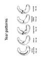
- FIGS. 4A-4Eillustrate various tear patterns or injuries to a meniscus. Tears may be vertical/longitudinal ( FIG. 4A ), oblique ( FIG. 4B ), degenerative ( FIG. 4C ), including radially degenerative, transverse or radial ( FIG. 4D ) and horizontal ( FIG. 4E ).
- Most prior art devices for suturing or repairing the meniscusare only capable of reliably repairing vertical/longitudinal tears. Such devices are not typically useful for repairing radial or horizontal tears.
- prior art device mechanismshave a high inherent risk for iatrogenic injury to surrounding neurovascular structures and chondral surfaces.
- the present inventionrelates to suture passers.
- suture passer deviceshaving a bent or bendable first jaw extending from an elongate body, and a second jaw that is independently axially slideable relative to the elongate body (and/or first jaw) to form a distal-facing opening between the first and second jaws into which target tissue may be held and sutured by extending a tissue-penetrator (e.g., needle) between the first and second jaws.
- tissue-penetratore.g., needle
- These devicesmay be configured to pass a suture multiple times through the tissue (e.g., passing both first and second ends of a suture) to create an entire loop of suture around a tissue such as a torn meniscus.
- this devicemay be adapted for use with loops, snares, baskets and other suture passing aids.
- the devices described hereinmay be adapted to include an indicator (e.g., optical indicator) showing where the tissue penetrator (e.g., needle) of the suture passer will engage with the opposite (e.g., upper) jaw of the suture passer.
- the suture passers describe hereinare adapted so that the lower jaw moves axially both independently, e.g., to retract/extend for positioning around a target tissue, and in conjunction with closing of the jaws, e.g., upper jaw motion, around tissue so that the needle extending from the lower jaw contacts with the upper jaw in a predictable fashion.
- suture passersthat provide a tactile and/or audible feedback to the user when the tissue penetrator element is extended (e.g., fully extended).
- the devicesare adapted so that the lower jaw has a substantially lower profile by reducing the arc of the needle exit, by axially separating the lower jaw into a first (e.g., proximal) region controlling the axial translation (motion) of the lower jaw and a second (e.g., distal) region that contains all of the features of the tissue penetrator pathway; these different regions may have different heights, allowing nesting into the shaft particularly near the proximal end of the device.
- a first (e.g., proximal) regioncontrolling the axial translation (motion) of the lower jaw
- a second (e.g., distal) regionthat contains all of the features of the tissue penetrator pathway
- suture cartridges and devicesconfigured to be used with pre-loaded suture cartridges.
- the first or second jawmay hold the tissue penetrator within an internal passage, and the tissue penetrator may be extended between the distal-facing opening to push and/or pull a suture between the first and second jaws.
- the tissue penetratormay be any appropriate material, but shape memory materials (e.g., shape memory alloys, plastics, etc.) are of particularly interest.
- the tissue penetratormay have a sharp (e.g., pointed, beveled, etc.) distal tip for penetrating tissue.
- the tissue penetratormay be biased (e.g., pre-bent) in a curve or bend.
- the tissue penetratore.g., needle
- the tissue penetratormay extend from a side region of the first or second jaw, extend across the distal-facing opening, and connect to an opening on the side region of the opposite (e.g., second or first) jaw from which it extends.
- This openingmay include a suture capture region that holds the suture passed by the tissue penetrator.
- the suture capture regionmay be a suture retainer that holds the suture when passed by the tissue penetrator.
- the suture retainermay be a deflecting or deflectable clamping region, a hook, or the like.
- the tissue penetratormay be configured to bend as it extends from the jaw and across the distal-facing opening.
- the tissue penetratormay be pre-biased to assume a bent or curved configuration as it extends from within a jaw.
- the tissue penetratormay extend approximately perpendicular to the side of the jaw housing it.
- the jawincludes a tissue penetrator deflection (e.g., ramped) region that helps deflect the jaw.
- the jaw housing the tissue penetratordoes not include a deflector.
- suture passersfor forming a loop of suture around a target tissue
- the suture passercomprising: an elongate body extending distally and proximally along a long axis; a first jaw extending from a distal end region of the elongate body wherein the first jaw is bent or bendable at an angle relative to the long axis; a second jaw configured to slide axially along the long axis distally and proximally relative to the elongate body, further wherein the first jaw and the second jaw form a distal-facing opening when the second jaw is extended distally and wherein the second jaw is retractable proximally so that it does not form the distal-facing opening with the first jaw; a tissue penetrator configured to extend across the distal-facing opening between the first jaw and the second jaw to pass a suture there between; and a plate having a keyhole capture region, wherein the keyhole capture region comprise a capture pathway including a channel extending through the plate
- the capture pathwaymay comprise an opening mouth at an edge of the plate that tapers to a narrower channel before the release pathway.
- the release pathwaycomprises an enlarged opening having a larger diameter than the region of the capture pathway adjacent to the release pathway.
- the bendmay be configured to retain the suture immediately after it is passed into the keyhole capture region by the tissue penetrator.
- the plateis configured as a suture stripper.
- the devicemay also include a suture having an enlarged distal end region configured to be retained by the keyhole capture region, further wherein the diameter of the enlarged distal end region is greater than the diameter of the capture pathway but less than the diameter of a portion of the release pathway.
- the enlarged distal end regionmay comprise a knot.
- Also described herein are methods of passing a loop of suture around a target tissuecomprising: placing a first jaw of a suture passer adjacent to a first side of a target tissue, wherein the first jaw extends from a distal end of an elongate body of the suture passer; extending a second jaw of a suture passer adjacent to a second side of the target tissue to form a distal-facing mouth with the first jaw, wherein the second jaw extends in a distal direction from the distal end of the elongate body of the suture passer; extending a tissue penetrator between the first and second jaws of the distal facing mouth while pushing a capture member connected to a suture with the tissue penetrator; retracting the tissue penetrator without the capture member or suture back between the first and second jaws of the distal facing mouth; repositioning the first and second jaws relative to the target tissue; extending the tissue penetrator between the first and second jaws of the distal facing mouth and capturing the capture
- the step of placing the first jawmay comprise placing the first jaw adjacent to the target tissue with the second jaw retracted proximally so that the distal end of the second jaw is adjacent or proximal to the distal end of the elongate body of the suture passer.
- the step of placing the first jawcomprises bending the first jaw relative to the elongate body.
- suture passer devicesfor passing a suture, the device comprising: an elongate body extending distally and proximally along a long axis; a first jaw extending from a distal end region of the elongate body wherein the first jaw is bendable at an angle relative to the long axis; a second jaw having a sharp, tissue penetrating distal tip, wherein the second jaw is configured to be manually slid axially along the long axis distally and proximally relative to the elongate body, further wherein the first jaw and the second jaw form a distal-facing opening when the second jaw is extended distally and wherein the second jaw is retractable proximally so that it does not form the distal-facing opening with the first jaw; a tissue penetrator configured to extend across the distal-facing opening between the first jaw and the second jaw to pass a suture there between; and a cam surface coupled to the second jaw and configured to move the second jaw axially in conjugate
- suture passer devicefor passing a suture and providing feedback to the user, the device comprising: an elongate body extending distally and proximally along a long axis; a first jaw extending from a distal end region of the elongate body wherein the first jaw is bent or bendable at an angle relative to the long axis; a second jaw having a sharp, tissue penetrating distal tip, wherein the second jaw is configured to slide axially along the long axis distally and proximally relative to the elongate body, further wherein the first jaw and the second jaw form a distal-facing opening when the second jaw is extended distally and wherein the second jaw is retractable proximally so that it does not form the distal-facing opening with the first jaw; a tissue penetrator configured to extend across the distal-facing opening between the first jaw and the second jaw to pass a suture there between; and an audible feedback actuator configured to provide an audible signal when the tissue peripheruv
- FIGS. 1A and 1Billustrate the anatomy of the meniscus, one exemplary tissue that may be sutured using the devices described herein.
- FIG. 2illustrates the anatomy of the meniscus, including the capsule and associated vascular tissue.
- FIG. 3illustrates the structure of a meniscus.
- FIGS. 4A-4Eillustrate various tear patterns that may be repaired using the invention described herein.
- FIGS. 5A-5Cshow one variation of a suture passer.
- FIGS. 6A , 6 B, and 6 Dshow top and two side perspective views, respectively of the distal end of the suture passer shown in FIG. 5A .
- FIG. 6Cillustrates the arrangement of the tissue penetrator and suture stripper in the distal end region of the suture passer of FIG. 5A .
- FIGS. 7A-7Cshow a suture stripper including a stripper plate ( FIG. 7B ) and base ( FIG. 7C ).
- FIGS. 8A and 8Bshow side perspective views of the distal end region of a jaw including a suture stripper.
- FIGS. 9A-9Cshow variations of jaws (e.g., second jaws) of a suture passer.
- the variation shown in FIG. 9Aincludes a deflection region for deflecting a tissue penetrator at the widest point of the jaw profile.
- FIG. 9Dshows the variation of FIG. 9A with the tissue penetrator extended.
- FIG. 9Eshows the variation of FIG. 9B with the tissue penetrator extended.
- FIG. 9Fshows the variation of FIG. 9C with the tissue penetrator extended.
- FIGS. 10A-10Hillustrate use of a suture passer described herein to form a loop around a target tissue.
- FIGS. 11A-11Dillustrate one variation of a suture passer as described herein, adapted to pass a suture through the tissue twice without having to re-load.
- FIGS. 12A-12Iillustrate a variation of a suture passer describe herein, adapted to pass a suture through the tissue twice without having to re-load.
- FIGS. 13A-13Dillustrate operation of a suture passer as described in FIG. 12A-12I .
- FIGS. 14A-14Dillustrate another variation of a suture passer device including suture snaring (grasping) and release feature for passing a suture through a tissue to form a loop around the target tissue.
- FIGS. 15A-15Dillustrate operation of a suture passer as shown in FIGS. 14A-14D .
- FIGS. 16A-16Gillustrates a suture passer device and suture capture element passing a suture twice through a target tissue to form a loop of suture around the target tissue.
- FIGS. 17A-17Billustrate variations of suture capture elements as described herein.
- FIGS. 18A-18Ishow operation and aspects of a suture passer using an expandable capture element.
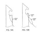
- FIGS. 19A and 19Bshow alternative suture capture elements engaging a tissue penetrator.
- FIGS. 20A-20Billustrate clamping of tissue (e.g., meniscus tissue) between the jaws of a suture passer.
- tissuee.g., meniscus tissue
- FIGS. 21A-21Billustrate the contact points of a suture passer with and without conjugate motion when clamping tissue between the jaws of the suture passer.
- FIG. 22illustrates a mechanism for achieving conjugate motion between an axial moveable lower jaw and a hinged/pivoting upper jaw.
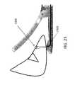
- FIG. 23illustrates operation of a suture passer device including a visual marking/notification element that projects light though the tissue to indicate the path that the needle (tissue penetrator) will take.
- FIGS. 24A-24Cillustrate a suture passer device having an audible/tactile feedback indicating the extension of the tissue penetrator.
- FIG. 25Ashows a section through a “thin” variation of a suture passer.
- FIGS. 25B-25Dillustrate enlarged views of various region of the suture passer of 25 A.
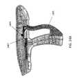
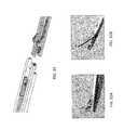
- FIG. 26shows the distal end region of the suture passer of FIG. 25A .
- FIGS. 27A and 27Bshow portions of the suture passer of FIG. 25A adapted to reduce the height of the device.
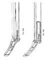
- FIGS. 28A and 28Bshow examples of suture passers having full elongate body housing ( FIG. 28A ) and a partial or c-shaped elongate body housing ( FIG. 28B ) from a top perspective view.
- FIGS. 29A and 29Bshow bottom perspective views of the same suture passers of FIGS. 28A and 28B , respectively.
- FIG. 30shows a pre-loaded suture cartridge getting inserted into a suture passer.
- FIG. 31shows the engagement region of the distal end component of the suture passer of FIG. 30 and the proximal end of the suture passer.
- FIG. 32A-32Billustrate suture passers that have been pre-loaded with sutures from bottom and top perspective views, respectively.
- sutures passersare sutures passers. These suture passers may be used arthroscopically, and may be used to pass one or more length of suture.
- the suture passers described hereininclude an elongate body and a first jaw member (e.g., first jaw) extending from the distal end of the elongate body, wherein the first jaw is bent or bendable relative to the distal to proximal axis of the elongate body.
- the first jawis hinged near the distal end region of the elongate body.
- Some variations of the suture passers described hereininclude a second jaw member (e.g., second jaw) that is configured to slide axially (proximally and distally) relative to the elongate body and/or first jaw.
- the second jawmay be configured to slide axially sufficiently far proximally so that the distal tip of the second jaw is proximal to the distal end of the shaft (e.g., completely retracted).
- the first and second jawsmay be configured to form a distal-facing opening into which tissue may be held.
- the suture passers described hereinmay also include a flexible, bendable, or pre-bent tissue penetrator for passing a suture through the tissue.
- the suture passermay also include a handle at the proximal end with one or more controls for actuating the first and/or second jaws and the tissue penetrator.
- the tissue penetratormay exit the second jaw from the side of the second jaw and extend across a distal-facing opening to engage an opening in the opposite jaw (e.g., the first jaw), where a suture may be secured and/or released.
- the suture passers described hereinmay have a second jaw having a maximum diameter (e.g., maximum height) along the length of the second jaw of less than about 0.11 inches, 0.10 inches, 0.09 inches, 0.08 inches, 0.07 inches, 0.06 inches, 0.05 inches, 0.04 inches, 0.03 inches, 0.2 inches, 0.01 inches, etc.
- the second jawmay be any appropriate width.
- the widthmay be approximately 0.15 inches.
- a numeric valuemay have a value that is +/ ⁇ 0.1% of the stated value (or range of values), +/ ⁇ 1% of the stated value (or range of values), +/ ⁇ 2% of the stated value (or range of values), +/ ⁇ 5% of the stated value (or range of values), +/ ⁇ 10% of the stated value (or range of values), etc. Any numerical range recited herein is intended to include all sub-ranges subsumed therein.
- FIGS. 5A-5Cillustrate suture passers that have a first jaw and a second jaw that may be controlled to form a distal-facing opening across which a tissue penetrator may extend to pass a suture through tissue between the first and second jaws.
- the suture passer ofhas a tissue penetrator that extends distally from a distal opening in the first jaw.
- the tissue penetratortravels in a sigmoidal path (e.g., approximately “S-shaped”, and is deflected twice, once upon leaving the lower jaw, and once upon contact with the upper jaw) from out of the second jaw, though any intervening tissue, to first jaw.
- One or more length of a suture(including two lengths of the same suture, e.g., two ends of the same suture) can be loaded (including pre-loaded) into the device and passed through the tissue.
- the suture passer show in FIGS. 5A-5Cis also configured so that the first (e.g., upper) jaw can pivot to assume a different angle relative to the elongate body of the device, and the second jaw is axially slideable or extendable distally from the distal end of the elongate member to form a distal-facing mouth with the first jaw.
- the proximal handleincludes a plurality of controls for controlling the pivoting of the first jaw, the axial sliding of the second jaw, and the extension/retraction of the tissue penetrator from the second jaw.
- FIG. 5Bshows the device of FIG. 5A with the outer housing of the proximal handle 3901 removed, revealing some of the connections between the controls and the device.
- the distal most control 3905the proximal handle is configured as a trigger or lever that controls the motion of the first jaw (“first jaw control”).
- the first jaw controlmay be pulled to reduce the angle of the first jaw relative to the long axis of the elongate member 3907 .
- the first jaw controlis pinned and allowed to drive a tendon in the elongate member distally when compressed to drive the first jaw down (reducing the angle between the first jaw and the long axis of the elongate member).
- This pivoting motionmay also be referred to as scissoring (scissoring motion).
- a distal control 3913is also configured as a lever or trigger, and may be squeezed or otherwise actuated to extend and/or retract the second jaw to form a distal-facing mouth with the first jaw, as shown in FIGS. 5A-5B .
- the controlis further configured to control deployment of the tissue penetrator in the sigmoidal path. For example, in some variations squeezing the distal control after completely extending the second jaw may deploy the tissue penetrator from the second to the first jaw so that the distal end of the tissue penetrator extends out of the first jaw. As it extends between the first and second jaw, the tissue penetrator may carry a first length (bight) of suture through the tissue.
- the suturemay be removed from the tissue penetrator and held (e.g., by a stripper) in the first jaw.
- the tissue penetratormay withdraw back into the second jaw.
- Actuating (e.g., squeezing) the distal control 3913 againmay result in the extending the tissue penetrator (along with any second length of suture) back through the tissue from the second jaw to the first jaw, where the second length of suture can be retained.
- the controlse.g., to control motion of the first and/or second jaw
- Additional controlsmay also be included in the proximal handle, include a suture loading control (e.g., switch, toggle, etc.) for loading and/or tensioning the suture within the second jaw.
- FIGS. 6A-6Dshow an enlarged view of the distal end of the device of FIGS. 5A-5C .
- the first jaw 4003is thin and slightly radiused (e.g., curved), and is hinged to the elongate shaft region of the device.
- the first jawis also connected to a control (handle, etc.) on the proximal handle by a push/pull member (tendon, wire, rod, etc.), allowing adjustment of the angle of the first jaw relative to the elongate member.
- FIG. 6Cthe first and second jaws have been removed from the distal end of the device shown in FIG. 6B , revealing the tissue penetrator 4007 within the second jaw and a suture stripper 4009 (suture retainer) in the first jaw.
- FIG. 6Dshows the distal end of the device of FIG. 6B after the tissue penetrator has been extended across the distal-facing mouth.
- FIGS. 8A and 8Billustrate one variation of a first jaw region having a suture stripper.
- the suture stripperis visible from the distal opening at the distal end of the jaw.
- the stripperincludes a stripper plate 4203 with a saw-toothed edge 4205 .
- the jawalso includes a receiver region for the stripper plate having a sawtooth edge 4207 .
- FIGS. 7A-7Cshow greater detail on one variation of a suture stripper that may be used. This variation is the same as the variation shown in FIGS. 8A and 8B .
- a suture strippermay be present on the second jaw (e.g., where the tissue penetrator is configured to pass a length of suture from the first jaw to the second jaw).
- the stripperincludes a flexible plate 4101 that is fixed at the proximal end (e.g. to the first jaw), and pressed against a receiving plate 4103 at the distal end 4105 .
- the receiveris not a separate receiving plate, but merely a region of the jaw.
- both the suture stripper plate 4101 and the receiver 4103may include an edge that is adapted to catch the suture.
- both the plate 4101 and receiver 4103include edges having teeth 4105 and 4107 .
- the teethare saw-tooth structures that are adjacent (or abutting) in the first jaw.
- the tissue penetratormay pass between the plate 4101 and the receiver 4103 by deflecting the plate 4101 ; as the end of the tissue penetrator passes the edges 4105 and 4107 , a length of suture held by the tissue penetrator may be caught by the stripper and held between the plate and receiver as the tissue penetrator is withdrawn.
- a suture passer having a distally-extending tissue penetratormay be used to repair a tissue such as the meniscus of the knee.
- the devices and methods described hereinmay be used to pass a loop of suture and specifically, may be used to form a vertical or horizontal stitch to repair tissue.
- a vertical stitchtypically provides the strongest repair with the least amount of displacement relative to horizontal stitches or other “all-inside” approaches.
- the devices and methods described hereinmay also be referred to as “all-inside” devices and meniscal repair techniques allow the meniscus to be sutured directly.
- the suture passers described hereinmay place a fully-circumferential, vertical stitch around meniscal tears. This stitch may provide uniform compression along the entire height of the meniscus and maintain coaptation of the tear at both the inferior and superior meniscal surfaces.
- the distal extending tissue penetratordoes not penetrate the capsule wall, reducing or eliminating risk to posterior neurovascular structures.
- These featuresmay allow a greater healing response due to complete tissue coaptation along the entire substance of the tear, improved clinical outcomes due to the greater healing response and to the anatomic reduction and fixation of the meniscus tear, may avoid scalloping or puckering of the meniscus, and may result in less extrusion or peripheralization of the meniscus caused by over-tensioning of suture or hybrid tensioners to the capsule.
- These devicescan also be used to treat radial, horizontal, flap, and other complex tears in addition to longitudinal tears.
- the suture passer devices described hereincan be fired blindly where arthroscopy camera access is poor, as knee structures are protected from the needle path.
- the devicee.g., in FIG. 5C
- the second jaw in this exampleis relatively straight.
- the second jawmay be recessed (partially or completely) into the shaft, and may slide proximal-to-distal in order to slide under the meniscus along the tibial plateau after the first jaw is in place along the superior surface of the meniscus.
- the second jaw in this examplecontains a flexible needle, which moves vertically from the second to first jaw.
- a knot of suturemay be passed through tissue using a suture passer as describe above in which a pre-tide knot is used to help secure the length of suture being passed to the device.
- a pre-tide knotis used to help secure the length of suture being passed to the device.
- an end region of one or both (in variations in which two lengths of suture are being passed) lengths of sutureare knotted, and this pre-tied knot may be passed through the tissue by the tissue penetrator.
- the pre-tied knotmay or may not include a leader snare.
- two lengths of suturemay be passed through a tissue; both lengths may be pre-knotted, however only one of the pre-tied knots may include a leader snare and be configured to allow another length of suture to be pulled through using the leader snare.
- the suture passers described hereinmay include a second (e.g., lower) jaw that is thin (e.g., ⁇ 0.11 inches in diameter at the widest point). In general, thinner second jaws may be inserted into narrower and difficult to access body regions.
- the second jawin which the second jaw houses the tissue penetrator and the tissue penetrator extends across the distal-facing opening formed between the first and second jaw, the second jaw may include a deflection ramp or deflection structure to help deflect the tissue penetrator out of the jaw and across the distal-facing opening.
- the deflection ram or deflection structurein some variations may form a widened region of the second jaw.
- second jaws housing a tissue penetratormay be used, wherein each one has a different thickness and/or different size deflection region.
- the second jawincludes a deflection region 907 distal to the opening from which the tissue penetrator may be extended (extension of a tissue penetrator is illustrated in FIG. 9D ).
- the widest diameter portion 901 of the jaw in this exampleis the deflection region 907 .
- the widest diameter regionis less than approximately 0.15 inches (e.g., less than about 0.14 inches, less than about 0.13 inches, less than about 0.12 inches, less than about 0.11 inches, less than about 0.10 inches).
- FIG. 9Ba jaw housing a tissue penetrator is shown without a protruding deflection member.
- FIG. 9Eshows the jaw of FIG. 9B with a tissue penetrator 905 extending from the side of the jaw. In this example, the jaw is thinner than the example shown in FIG.
- the maximum diameter (e.g., maximum height) of the jaw 911is less than about 0.10 inches (e.g., less than 0.09 inches, less than 0.08 inches, less than 0.07 inches, less than 0.06 inches, etc.).
- FIG. 9Cshows another example in which the jaw is even thinner (e.g., less than 0.06 inches, less than 0.05 inches, less than 0.04 inches, less than 0.03 inches, etc.).
- the jawmay have a width. For example in some variations the width is between about 0.01 inches and about 0.15 inches.
- the tissue penetratoris typically thinner and narrower than the jaw so that it may fit within the jaw; the tissue penetrator (e.g., needle) may have a square, round, rectangular, or other cross-sectional area.
- the tissue penetratormay be configured as a ribbon-shaped tissue penetrator, having a sharp (e.g., pointed, beveled, etc.) distal tip region, and a suture retaining region (e.g., hook, eyelet, etc.).
- any of the jaws illustrated in FIGS. 9A-9Fmay be used as a second or lower jaw for a suture passer as illustrated above (e.g., FIGS. 5A-6B ).
- the suture passers shown in FIGS. 5A-6Binclude first and second jaws having atraumatic (e.g., non-tissue penetrating) distal tip regions.
- the distal tip region of both jawsare rounded and atruamatic so that they do not readily penetrate or cut the tissue.
- the distal tip region of a jawis tissue penetrating, allowing the jaw to be inserted into the tissue.
- the axially slideable jawe.g., the second jaw
- the suture passermay pass a suture in an angle within the tissue (including at a right angle, e.g., to form an approximately “L” shape).
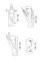
- FIG. 25Ashows a cross-section through a variation of a suture passer having a sliding lower jaw.
- Exemplary dimensions that contribute to the overall device heightinclude: the height of the lower jaw 2505 in order to contain the needle pathway, the height of the needle shaft 2511 , the height of the clamp rod 2509 , the height of the shaft 2507 necessary to maintain appropriate strength, and the height of the clamp link 2513 . These heights are illustrated in the enlarged views of the lower jaw ( FIG. 25B ), elongate body ( FIG. 25C ), and clamp link 2506 region ( FIG. 25D ). Even a small reduction in any of these heights, without sacrificing the performance parameters, may provide substantial gains in how and where the suture passer may be used.
- the lower jaw pathwaymay be truncated so that the arc in the lower jaw does not turn fully to 90 degrees, as previously described. See, e.g., FIG. 25B .
- the needlemay be configured to exit the lower jaw at a shallower angle ( ⁇ 90°, such as approximately 80°, approximately 70°, approximately 60°, etc.) while still contacting the upper jaw in a region sufficient for deflection distally to pass the suture as described above.
- a structural portion of the shaft that connects the two sides of the shaft togetherhas been moved from the top to the bottom.
- This changeis facilitated by breaking the lower jaw into two pieces, a first (e.g., distal) end part that contains all of the features of the needle pathway, and second (e.g., proximal) part that serves to translate the position of said distal end.
- the second, more proximal, pieceis not as tall as the distal piece so that it can nest within the shaft.
- the jog in heightis shown in FIG. 26 .
- the distal end 2607 of the lower jawcontains the needle pathway
- the proximal end 2605include the strucutre spine of the shaft.
- the transition between the two 2609allows for a very flat profile.
- the height of the needle shaft and clamp rodare reduced.
- the clamp rodmay move to actuate the hinged upper jaw.
- the clamp rod 2701may be made flat and attached to the shaft 2709 using a tongue-in-groove configuration while communicating through the open top in the shaft 2709 , as illustrated in FIG. 27A .
- the needle shaft 2703passes below the clamp rod over this portion of the elongate body.
- the lower jaw translation shaft 2705is a U-shaped element within the shaft 2709 that partially surrounds the needle shaft 2703 . The combination of these features minimize the amount of material needed to keep the necessary strength and rigidity.
- the clamp link(which contributes to the hinged motion of the upper jaw) is changed from having two holes with pins through them as shown in FIG. 6D to an alternate design that replaces the more proximal hole with a pin that is integrated into a the clamp link such that it mates with the clamp rod in a the manner shown in FIG. 27B .
- the elongate bodymay have a U-shaped cross-section.
- the upper jaw actuator(“clamp rod”) may be coupled to the hinge (clamp link) via a recessed connection within the footprint of the elongate shaft at one end, and within the upper jaw at the other end, as shown in FIG. 27A .
- the lower jaw membermay include a distal region that controls the needle actuation and a proximal region that includes the linear actuating components.
- FIGS. 28A-28B and 28 A- 29 Bcompare a device that does not include the U-shaped outer housing and recessed hinge ( FIGS. 28A , 29 A) with a device that does ( FIG. 28B , 29 B) in top ( FIGS. 28A-28B ) and bottom ( 29 A- 29 B) perspective views.
- the suture passers described hereinmay be used to pass a suture in a loop though tissue, so that the ends of the suture can be approximated (e.g., tied together, anchored, etc.).
- the suture passermay be loaded with a first length of suture, the first length of suture passed through the tissue, then the suture passer can be reloaded with a second length of the suture and repositioned, and the second length of the suture can then be passed through the tissue again.
- FIGS. 10A-10Killustrate on method of forming a loop through tissue in a meniscus.
- a suture passer(similar to the suture passer shown in FIGS. 5A-6D ) can be inserted through a working portal and advanced until the upper jaw is between the superior surface of the meniscus and the articular surface of the femoral condyle ( FIGS. 10A-B ).
- the lower jawis then extended forward so that it moves under the meniscus and the tissue penetrator (needle) trigger is actuated to complete the peripheral pass of the suture from the lower jaw to the upper jaw where it is atraumatically self-retained ( FIG. 10C ).
- the lower jawis retracted and device is removed ( FIG. 10D ).
- the suture passeris then re-loaded with the opposite suture strand and re-inserted while gently pulling on the suture such that the upper jaw is lead into the exact same tissue plane ( FIG. 10E ) the suture is again passed from lower jaw to upper jaw, this time positioned on the opposite side of the tear ( FIG. 10F ), and the lower jaw is again retracted and the device removed ( FIG. 10G ).
- a knotcan then be tied on the peripheral femoro-synovial junction (shown in FIG. 10H ). No cannula or sled are required for this technique, and the method avoids tissue bridging that can occur if the suture re-enters the tissue in a slightly different location.
- the suture passermay be adapted so that the device does not need to be withdrawn out of the tissue to be loaded with the second suture.
- the first and second (or more) lengths of suturemay be pre-loaded onto the suture passer.
- the suture passermay be adapted so that the tissue penetrator (needle) is adapted for both pushing a suture from the lower jaw to the upper jaw and pulling suture from the upper jaw back to the lower jaw (or vice-versa).
- the suture passer devices described hereinmay be configured so that the end of the suture, or a suture linked element connected to the suture, is first pushed by the tissue penetrator through the tissue from the first (e.g., lower, axially moving) jaw to the second (e.g., upper, bending) jaw, then the device is moved relative to the tissue and the tissue penetrator is then extended to collect the end of the suture or the suture linked element, and retracted back through the tissue to pull the suture back through the tissue.
- a full stitchmay be passed through the tissue. In the meniscus, the full stitch may be passed within the joint capsule without removing the device between passes.
- An exemplary sequence of operationis as follows: with a suture loaded onto the device, the device is inserted into the joint capsule and place the device in position for the first pass; pass (“fire”) the first leg of the suture; move the device to the second location; fire the device to retrieve the suture, and remove the device from the joint capsule. The suture can then be released from the device and the knot tied (closing the suture loop).
- This method and devices for implementing itmay be referred to as “push/pull” since one end of the suture is first “pushed” through tissue by the needle and captured in the upper jaw, and it is then moved to the second position, and the needle comes up through the tissue to retrieve the captured end and pulls it back down into the lower jaw.
- a suture that is loaded into the suture passercontaining a suture retaining plate on the second jaw that is configured to releasably hold the distal end of a suture, where the plate is adapted to have a “keyhole” passage 1101 through which the suture may be entered and temporarily retained.
- this retaining plate with the keyholeis a stripper plate as shown and described above, but with the addition of the keyhole structure.
- the keyhole retaining plateis positioned adjacent to a suture stripper.
- This keyhole suture retainer on the plate and/or suture stripperhas an opening at one end that has a larger diameter than the suture; the passage connecting the edge of the suture (which may have a large mouth 1105 that narrows to the narrower passage) typically has a narrower diameter (D p ).
- the keyhole passagetypically includes a bend or bends (elbow region) before opening into the large opening mentioned. The elbow region may retain the suture in this narrow region until the tissue penetrator extends back across to retrieve it, as will be described below.
- FIG. 11Aillustrates one variation of a suture stripper 1101 with such a keyhole passage.
- This variationmay be used with a suture having an enlarged distal end feature, such as a knot, ferrule, or other enlarged region attached to the distal end (or near the distal end) of the suture.
- an enlarged distal end feature of the sutureis an overhand knot tied at the end of the suture.
- a second embodimentis a plastic or metal part that is overmolded, glued, tied or otherwise affixed to the end of the suture.
- the stripper with the keyhole cutoutmay capture the enlarged region of the suture on the end of the suture.
- the adapted suture stripperis attached to the inferior surface of the upper jaw. See, e.g., FIGS. 11 A- 11 Cc.
- the keyhole cutout region 1105is shaped in a fashion that allows it to hold the suture at various states while facilitating release of the suture during the second phase (pull) of the procedure.
- the keyhole-adapted stripper 1101may be made from any appropriate material, including plastic or sheet metal.
- FIG. 11Bshows the distal end of a suture with an upper jaw member that includes the plate having a keyhole opening.
- a separate suture stripper 1109is positioned above the plate with the keyhole feature.
- a tissue penetratormay pass under the suture stripper and the plate with the keyhole feature and the stripper scrapes the suture off the tissue penetrator as the tissue penetrator retracts.
- FIG. 11Cillustrates a top view of the upper jaw of FIG. 11B , showing the distal end of the jaw, with the opening 1105 into the keyhole region that narrows to guide the suture into the bend/elbow region and eventually to the larger opening.
- FIG. 11Dshows the distal end of the suture passer after the suture with the enlarged distal end feature 1105 has been deposited into the keyhole cutout 1101 of the upper jaw.
- FIGS. 12A-12Billustrate operation of the plate with the keyhole cutout feature 1201 and a suture with an enlarged distal end feature 1205 .
- the needleis shown beneath the trap feature (the keyhole cutout 1201 ), which has been made transparent to show the needle position.
- the enlarged distal end feature 1205enters the keyhole cutout through the large opening at the edge.
- the needlepasses the first leg of the suture and the knot at the end of the suture (enlarge distal end feature 1205 of the suture).
- the needlethen retracts, leaving the knot and suture behind, and tension is applied to the suture to locate it securely in the correct position, as shown in FIG. 12B .
- FIG. 12Athe needle is shown beneath the trap feature (the keyhole cutout 1201 ), which has been made transparent to show the needle position.
- the enlarged distal end feature 1205enters the keyhole cutout through the large opening at the edge.
- the needlepasses the first leg of the suture and the knot at the end of the
- FIG. 12Cshows a side perspective view of the method being applied in a meniscal tear (tissue 1211 with tear 1214 ).
- the suture passermay be placed in a second location on the meniscus (e.g., without removing it from the knee joint or having to reload) where the second suture leg is intended to be passed.
- the needlemay then be passed through the tissue, and the angled region 1216 at the tip of the needle pushes the suture into the release pathway of the keyhole cutout region 1201 , which is shown as an en enlarged circular region.
- the release pathwayis typically an opening having a larger diameter than the enlarged distal end feature of the suture.
- the release pathwaymay also include a channel or ramp on the plate that guides the suture to the enlarged opening.
- FIGS. 12G and 12Hshow the needle just before it picks up the suture on its way back to the lower jaw.
- FIG. 12Ishows the needle with the suture (and enlarged distal end feature 1205 ) held within the hook region of the needle.
- the needle (tissue penetrator) used for any of these proceduresmay be adapted to include a suture “pushing” region (hook region, etc.) and a suture “pulling region” (hook region).
- the suture pushing regionis typically located more distally than the pulling region.
- the needlehas a distal-end adapted with a pushing region in which a notch is cut out of the distal end to hold the suture (and enlarged distal end region) as it pushes through the tissue.
- a hook regionProximally along the needle, a hook region, which is oriented so that the hook opening extends distally, is adapted for pulling the suture (and enlarged distal end region) back through the tissue towards the lower jaw.
- FIG. 12Fillustrates another example of a needle in which the pushing region is not at the distal-most end, but is located proximal to the distal end.
- the needleincludes a ramped region at the distal end.
- FIGS. 13A-13Dshow a profile view of the procedure using the keyhole cutout plate and the suture having an enlarged distal end feature.
- the suture passeris positioned around the meniscus, as previously described.
- the tissue penetratormay be extended, as shown in FIG. 13B , to push the suture through the meniscus on a first side of the tear in the meniscus 1305 .
- the sutureis retained in the keyhole cutout plate, and the suture passer may be repositioned on the meniscus, as shown in FIG. 13C (also not shown to scale).
- the needlemay be extended back through on a second side of the tear (e.g., opposite from the first side), so that the knot is pushed by the returning needle into the large opening of the keyhole cutout plate (not shown) and captured by the pulling hook of the needle and withdrawn back through the tissue with the retracting needle, as shown in FIG. 13D .
- needleand “tissue penetrator” are used interchangeably in this disclosure, though the broader “tissue penetrator” term applies.
- FIGS. 14A-14DAnother variation of a suture passer configured as a push/pull suture passer for forming a loop is shown in FIGS. 14A-14D .
- the deviceincludes a suture passer similar to those described above in FIGS. 5A-6D , but adapted to include a releasable snare.
- the snareis shown having an open loop 1401 around the distal-facing opening of the upper jaw.
- the snaremay be housed on the side of the device and retractable into this housing (e.g., snare guiding tube 1407 ).
- the opening of the snare loop 1401may be positioned to accept the first leg of a suture.
- the snare loop 1401can be tightened and cinch the suture, thereby securing it to the device as it moves to the next position.
- the loop of the snaremay be cinched by pulling the snare proximally so that the loop enters into the housing and closes over the suture, as described below.
- the needlecomes up again through tissue to retrieve the suture.
- the snarethen release, and the needle may be pulled back through the tissue to the lower jaw.
- FIGS. 14B-14Dillustrate these steps.
- the snaremay be a wire snare (e.g., nitinol, stainless steel, etc.), which runs through tubing alongside of the device.
- wire snaree.g., nitinol, stainless steel, etc.
- the first leg of the suturehas been passed through the tissue (not shown) and up through the snare opening.
- the snareis pulled so that it retreats into the tunnel (snare guiding tube) along the side of the device, bringing the suture with it, and securing the suture in the closed loop, at least partially held within the narrow constrains of the snare guiding tube, while the device is repositioned.
- the snare loopmay release its hold on the suture by extending the wire snare out of the snare guiding tube.
- the needlemay be “fired” (sent across the tissue to the upper jaw) this time hooking the suture. Since the suture has been released by the snare, the suture is free to be pulled back through the tissue by the tissue penetrator and into the lower jaw.
- FIGS. 15A-15Dshow an illustration of this method applied to a meniscus.
- the suture passerAfter positioning the suture passer around the meniscus (shown in FIG. 15A ), the suture is pushed through the tissue to the upper jaw, where the suture passes through the snare opening (not shown) and the snare is pulled distally to capture the suture and hold it in the upper jaw while the suture passer is repositioned, as shown in FIG. 15C .
- the tissue penetratoris passed through the tissue again, the snare loop is released, and the tissue penetrator hooks and retracts the suture, withdrawing it back through the tissue to the lower jaw ( FIG. 15D ).
- FIGS. 16A-16Gillustrate another variation of a system and device for passing a loop of suture through the tissue.
- the sutureis coupled at or near its distal end with an expandable capture element that makes it easier for the needle to recapture the end of the suture and pull it back through the tissue after it has already been passed through the tissue a first time.
- the capture elementis typically expandable and collapsible, so that it present a small profile within the suture passer and/or within the tissue as it is being passed, but expands or opens to form a relatively large, and easy to capture profile once it has been passed through the tissue a first time.
- the suture passermay be adapted to hold and grab the expandable capture element.
- the capture elementmay be connected to a suture in any appropriate manner, including by tying, gluing, crimping, etc.
- the capture elementmay be flexible, and may be formed of metal, plastic, or the like.
- the capture elementis formed of a nitinol wire.
- a flexible loop or basket(e.g., made of nitinol), may be used to connect to the suture and be passed by the tissue penetrator which can grab the capture element in order to make a complete circle around a tear. The capture element, connected to the suture, would then shuttle a suture in its place through the tissue.
- FIG. 16Ashows an example of a suture passer that may be used, with the tissue penetrator extended.
- the tissue penetratormay be similar to that shown in FIGS. 5A-6D .
- the tissue penetratoris adapted to hold and release a capture element coupled to a suture in the lower jaw, and to allow the capture element to expand when released into the upper jaw.
- FIGS. 16B-16Gare simplified illustrations of a method of forming a loop of suture around a tear in a meniscus (lateral tear 1609 ).
- the upper and lower jaws(which are extended around the meniscus) are not shown in FIGS. 16B-16G , although the suture, collapsible capture element and tissue penetrator are shown.
- FIG. 16Ashows an example of a suture passer that may be used, with the tissue penetrator extended.
- the tissue penetratormay be similar to that shown in FIGS. 5A-6D .
- the tissue penetratoris adapted to hold
- the suture passeris preloaded with the expandable capture element, and pushes it through the meniscus, from the inferior to the superior side. Once passed, the tissue penetrator retracts back through the meniscus to the lower jaw, and the collapsed capture element is free to expand.
- the capture elementis a loop of wire that is biased open; as the tissue penetrator retracts back to the lower jaw, as shown in FIG. 16C , the loop expands open on the superior side of the meniscus.
- the capture element in this exampleis large enough to expand across the tear in the meniscus; the anatomical constraints of the tissue around the meniscus allow the expandable capture element to expand only on the superior surface in the predictable direction. Because the tissue penetrator pushed distally (up the superior surface of the meniscus) the loop expands in this direction. Re-orienting the suture passer may allow it to direct how and where the expandable capture element expands.
- FIG. 16Dthe suture passer has been repositioned relative to the tear in the meniscus, so that the tissue penetrator may pass on the opposite side of the tear, as illustrated.
- the tissue penetratorextends out of the superior side of the meniscus and though the loop of the capture element.
- FIG. 16Ethe proximal end of the suture (which is attached distally to the capture element) is pulled proximally to tighten the loop around the tissue penetrator.
- the tissue penetratoris then retracted, pulling the capture element with it, as shown in FIG. 16F .
- the capture elementAs the capture element is drawn through the tissue, it again collapses. Once it has been withdrawn through the tissue, pulling the suture behind it, the capture element may be removed, and the ends of the suture secured, as shown in FIG. 16G .
- a single tissue penetratoris shown placing the loop and then retrieving the loop.
- An alternative embodimentcould have a lower jaw that contains two tissue penetrators (e.g., needles), one for placing the loop and another for retrieving the loop.
- a third embodimentcould contain two independent lower jaws, each containing its own needle. As in the second embodiment, one needle would place the loop and the other needle would retrieve the loop. By placing the needles in separate lower jaws, the two lower jaws could be independently actuated to allow the surgeon to adjust the distance between the two vertical legs of the stitch.
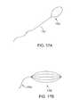
- FIG. 17Ashows one variation of an expandable capture element that is connected to a suture.
- the expandable capture elementis configured as a nickel-titanium (e.g., nitinol) wire that forms a loop but is biased in the open configuration.
- the suture 1703is connected to the loop 1701 (either directly or through a leader); for example, the suture may be tied to the flexible loop.
- FIG. 17Bshows another variation of an expandable capture element, configured as a plurality of loops 1706 that are flexible but biased open (expanded).
- a suture 1703may be affixed to the plurality of loops (“basket”) 1706 .
- the plurality of loopsmay help ensure that the tissue penetrator hook (e.g., pulling hook) catches the capture element; this feature may alleviate the need to cinch the suture (e.g., pull the suture proximally).
- the expandable capture elementis not extended substantially from the upper jaw member, but remains within the jaw member and is held by the upper jaw member after withdrawing the tissue penetrator so that when the tissue penetrator is again extended through the jaw, the tissue penetrator will pass through it, and the capture element can be pulled onto the tissue penetrator to engage with it so that it can be withdrawn back through the tissue.
- FIGS. 18A-18Cillustrate this variation.
- the tissue penetratorhas an upper jaw member that includes a holding region 1805 for the capture element; in FIG. 18A , the holding region is defined on the underside of the upper jaw by a retaining plate 1805 , as also illustrated in FIG. 18B .
- the nitinol loop 1801is pushed by the needle so that the expandable capture element expands into the space under the upper jaw defined by the plate, as shown in FIG. 18B .
- the holding regionmay be defined by the upper jaw so that the capture element (e.g., loop) is held with an orientation that prevents the capture element from engaging with the needle when it is pushed fully distally.
- FIG. 18Athe tissue penetrator has an upper jaw member that includes a holding region 1805 for the capture element; in FIG. 18A , the holding region is defined on the underside of the upper jaw by a retaining plate 1805 , as also illustrated in FIG. 18B .
- FIG. 18Cshows a section through the holding region of the upper jaw, where a capture element 1801 is being held.
- the needle/tissue penetratorcan again be extended through the tissue and into the upper jaw, as shown in FIG. 18D .
- the needlemay pass through the loop of the capture element held in the upper jaw.
- the suturemay then be pulled proximally, reorienting the capture element and pulling it onto the needle so that it engages the needle and is pulled back through the tissue when the needle is withdrawn back though the tissue.
- FIG. 18Eshows cinching of the loop of the capture element
- FIGS. 18F-18Hshowing the capture element being withdrawn back to the lower jaw.
- FIGS. 18E and 18Gshow the suture 1803 is pulled to cinch the loop of the capture element onto the needle.
- FIGS. 18F and 18Gthe needle 1815 is shown capturing the loop of the capture element 1801 .
- FIGS. 18H and 18Ishow the tissue penetrator completely withdrawn (holding the capture element) into the lower jaw ( FIG. 18H ), and the device being withdrawn from the tissue, as shown in FIG. 18I , which pulls the rest of the collapsed loop from the meniscus, and pulls the suture into position.
- FIGS. 19A and 19Billustrate variations on the interaction between the capture element and the tissue penetrator.
- the tissue penetratorcouples with a loop of the capture element; thus the flexible loop can be preloaded onto the tissue penetrator before it is retracted into the lower jaw and primed to “fire” across the tissue.
- FIG. 19Billustrates one example in which a loop of suture is connected to the capture element that is also connected to a length of suture, as shown.
- the suture passers described hereinmay be used to pass sutures though tissue (and particularly meniscal tissue) having various thicknesses and dimensions by adjusting the bite (e.g., the angular distance between the upper and lower distal-facing jaws), adjusting the bite size may change the contact position of the needle/tissue penetrator as it extends from the lower jaw to the upper jaw.
- the lower jawmay refer to either the first jaw or second jaw, as the orientation may be relative; similarly the upper jaw may refer to the opposite jaw, in any orientation.
- the devices describe hereinare configured so that the devices tolerate changes in the contact point between the needle and the upper jaw, while still deflecting the needle distally as described above, it may be beneficial to know where on the upper jaw the needle will exit the tissue and contact the upper jaw. This may be referred to as targeting. It may be relatively less certain where the needle may exit the tissue when the bite size of the needle is smaller (e.g., when the jaws are more closed).
- Described hereinare methods and devices that allow the user to place a stitch in an intended location even when the jaws are relatively “closed” (e.g., small bite size), as when passing a suture in the more central regions of the meniscus.
- This uncertaintydoes not typically arise when placing a stitch at the periphery of the meniscus, when the bite size is relatively large, because the user can position the device as distal as it will go and blindly fire (see FIG. 20A ).
- FIG. 20Ashows the placement of a stitch near the periphery of a meniscus.
- FIG. 20Bshows a stitch near the apex of the meniscus.
- the surgeonis placing a stitch between the tear and the apex.
- the stitchwon't grab enough tissue to be secure, too close to the tear and the stitch could be sent up through the tear.
- the lower jawmay be completely covered by tissue, and the needle exit is invisible to the user.
- a stationary mark on the upper jawis problematic because it may not predict where the needle with exit/hit; the needle may hit the upper jaw in different locations based on clamp height.
- Described beloware methods and device (e.g., adaptations to devices) that may be used to target stitch placement.
- the lower (sliding) jawis configured to move conjugally with the clamping of the upper jaw, so as to maintain an approximate relative striking distance between the tissue penetrator and the upper jaw when passing the tissue penetrator across the jaws.
- FIG. 21Ashows a jaw moving though a large tissue thickness (e.g., a thick meniscus in this example).
- An exemplary “thick” tissue thicknessmay be 7.5 mm.
- the needlewill hit the upper jaw at a given location shown in FIG. 21A by the “X” 2105 .
- the location of this contact pointwill vary, as illustrated by the more proximal contact point “o” 2109 in FIG. 21B .
- the contact pointmay be corrected to ensure that the needle hits the upper jaw in the same location, 2107 .
- the lower jawmay move to the left 2111 , relative to the shaft, to deliver the suture to the “X” target on the upper jaw 2107 .
- the suture passermay be configured as described above so that the lower jaw can be moved axially (distally/proximally relative to the elongate axis), both independently (to form the distal-facing opening, and also in conjugate motion when clamping/unclamping the upper jaw to change the bite angle of the suture passer.
- the movement of the upper jaw and the conjugate motion of the lower jawcan both be controlled by the clamp trigger (refer to FIGS. 5A-5B , for example).
- the axial distance of the “X”may move at a nonlinear rate distally.
- the lower jawmay also travel at the same rate. This can be accomplished by having the lower jaw motion controlled by a cam profile on the needle trigger. An example of such a cam profile is shown in FIG. 22 .
- the lower jawinclude a cam follower 2205 that includes a camming surface that may also drive axial motion of the lower jaw when the upper jaw is moved.
- motion of the upper jawmay be configured so that the axial position is adjusted based on the angle of the upper jaw with the elongate, long axis, of the device.
- the lower jawmay still be manually and independently axially movable to extend/retract axially.
- the lower jawmoved in conjugate motion with the upper jaw only when the lower jaw member is fully extended first (e.g., manually fully extended).
- the conjugate motion between the upper jaw member and the lower jaw membermay be turned “on” or “off” for the device.
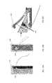
- FIG. 23illustrates on variation of a device including an optical fiber 2303 extending with (and part of) the lower jaw that project a spot of light (e.g., visible or visualizable light) through the tissue. This light may be from an LED, laser, or other appropriate source.
- a spot of lighte.g., visible or visualizable light
- a light sourceis placed on the lower jaw pointing toward the upper jaw to indicate where the needle will exit.
- the lightis strong enough, there should be a visible spot on top of the tissue that the user can use to place the stitch with confidence.
- the grip force required to actuate the needlemay be great enough that it is difficult for the user to feel the needle trigger's end of travel because the actuation force already placed high demands on the user's grip strength.
- the travel limiterbecause the force required to actuate the needle trigger feels may be great.
- a suture passer devicethat provides an audible “click” or some other cue is helpful to the surgeon to ensure that he or she has fully actuated the device.
- FIG. 24Ashows a cutaway view of the suture passer handle mechanism.
- the needle driver 2409is rigidly attached to the needle (not shown). As the surgeon grips the needle trigger 2405 , the needle driver 2409 translates forward. Because it is rigidly attached to the needle driver, the needle also translates forward as the needle trigger is gripped.
- the needle drivercontains a boss that, as it moves past a clicking element 2407 , bends the Clicking Element upward as shown in FIG. 24B . Once the boss has moved distally past the interfering portion of the clicking element, the clicking element is free to snap back down where it impacts a feature 2415 on the handle (see FIG. 24C ). This impact is enough to create an audible click that can also be felt in the user's hand.
- any other appropriate feedback actuator for providing audible and/or tactile feedback at or near the maximum extension of the needle and/or lower jawmay be used.
- the configuration described above in FIG. 24is a mechanical feedback actuator; in some variations the system may use one or more optical encoders and a piezo or other electronic technique for providing feedback to the user (e.g., electrical feedback actuator).
- FIG. 30Ashows an embodiment where the distal cartridge 3007 is comprised of the lower jaw component that contains the needle pathway, the needle, the needle sled (a connector that attaches the nitinol needle to a translatable element in the handle 3003 ), and a suture (not pictured).
- the same features that allow separation of the lower jaw into a distal (needle path) and proximal (actuation control) portions that may connect/snap togethermay allow substantial reductions in the device height (e.g., the shaft height).
- the proximal end of the cartridgemay contain features that allow each of the members requiring actuation, the needle and the lower jaw, to click or snap into a corresponding actuator in the handle (See FIG. 31 ).
- An actuator on the handlecan be activated by the user to disengage the connection features, facilitating removal of a used cartridge and readying the handle for loading a new cartridge.
- Suturesmay be contained in the cartridge in a manner similar to that shown in FIGS. 32A-32B .
- the embodiment in FIGS. 32A-32Bshow knots at the ends of the suture, however, these could also be loops or some other feature that creates a shape that is larger than the base suture diameter so that it does not slip through the cut-out in the needle.
- the advantages of a per stitch cartridgeinclude preloading the suture into the cartridge so the surgeon or the scrub nurse do not have to deal with as much suture management in the sterile field, as well as keeping the suture housed within the lower jaw so that it cannot get pinched between the inferior surface of the device and the anterior horn of the meniscus or the tibia.
- the above architectureallows the surgeon to place both legs of the suture without removing the device from the joint. This eliminates the possibility of tissue bridging.
- the handleis re-usable throughout the case.
Landscapes
- Health & Medical Sciences (AREA)
- Life Sciences & Earth Sciences (AREA)
- Surgery (AREA)
- Heart & Thoracic Surgery (AREA)
- Engineering & Computer Science (AREA)
- Biomedical Technology (AREA)
- Nuclear Medicine, Radiotherapy & Molecular Imaging (AREA)
- Medical Informatics (AREA)
- Molecular Biology (AREA)
- Animal Behavior & Ethology (AREA)
- General Health & Medical Sciences (AREA)
- Public Health (AREA)
- Veterinary Medicine (AREA)
- Surgical Instruments (AREA)
Abstract
Description
Claims (18)
Priority Applications (6)
| Application Number | Priority Date | Filing Date | Title |
|---|---|---|---|
| US13/844,252US9211119B2 (en) | 2007-07-03 | 2013-03-15 | Suture passers and methods of passing suture |
| EP14764051.0AEP2967548B1 (en) | 2013-03-15 | 2014-03-17 | Suture passer devices |
| PCT/US2014/030137WO2014145381A1 (en) | 2013-03-15 | 2014-03-17 | Suture passer devices and methods |
| JP2016503335AJP2016513570A (en) | 2013-03-15 | 2014-03-17 | Suture passer type device and method |
| HK16102796.4AHK1214748B (en) | 2013-03-15 | 2014-03-17 | Suture passer devices |
| US14/697,494US10524778B2 (en) | 2011-09-28 | 2015-04-27 | Suture passers adapted for use in constrained regions |
Applications Claiming Priority (17)
| Application Number | Priority Date | Filing Date | Title |
|---|---|---|---|
| US11/773,388US20090012538A1 (en) | 2007-07-03 | 2007-07-03 | Methods and devices for continuous suture passing |
| US12/291,159US8821518B2 (en) | 2007-11-05 | 2008-11-05 | Suture passing instrument and method |
| US12/620,029US20100130990A1 (en) | 2007-07-03 | 2009-11-17 | Methods of suturing and repairing tissue using a continuous suture passer device |
| US12/942,803US8562631B2 (en) | 2009-11-09 | 2010-11-09 | Devices, systems and methods for meniscus repair |
| US12/972,168US20110152892A1 (en) | 2007-11-05 | 2010-12-17 | Suture passing instrument and method |
| US12/972,222US20110087246A1 (en) | 2007-07-03 | 2010-12-17 | Methods and devices for continuous suture passing |
| US13/006,966US20110130773A1 (en) | 2007-07-03 | 2011-01-14 | Methods for continuous suture passing |
| US201113062664A | 2011-04-19 | 2011-04-19 | |
| US13/090,089US8663253B2 (en) | 2007-07-03 | 2011-04-19 | Methods of meniscus repair |
| US13/114,983US8702731B2 (en) | 2007-07-03 | 2011-05-24 | Suturing and repairing tissue using in vivo suture loading |
| US13/247,892US9861354B2 (en) | 2011-05-06 | 2011-09-28 | Meniscus repair |
| US13/323,391US9700299B2 (en) | 2011-05-06 | 2011-12-12 | Suture passer devices and methods |
| US13/347,184US8500809B2 (en) | 2011-01-10 | 2012-01-10 | Implant and method for repair of the anterior cruciate ligament |
| US13/462,760US8920441B2 (en) | 2007-07-03 | 2012-05-02 | Methods of meniscus repair |
| US13/462,728US8449533B2 (en) | 2009-11-09 | 2012-05-02 | Devices, systems and methods for meniscus repair |
| US13/462,773US8465505B2 (en) | 2011-05-06 | 2012-05-02 | Suture passer devices and methods |
| US13/844,252US9211119B2 (en) | 2007-07-03 | 2013-03-15 | Suture passers and methods of passing suture |
Publications (2)
| Publication Number | Publication Date |
|---|---|
| US20140276981A1 US20140276981A1 (en) | 2014-09-18 |
| US9211119B2true US9211119B2 (en) | 2015-12-15 |
Family
ID=51531027
Family Applications (1)
| Application Number | Title | Priority Date | Filing Date |
|---|---|---|---|
| US13/844,252Active2034-02-22US9211119B2 (en) | 2007-07-03 | 2013-03-15 | Suture passers and methods of passing suture |
Country Status (1)
| Country | Link |
|---|---|
| US (1) | US9211119B2 (en) |
Cited By (23)
| Publication number | Priority date | Publication date | Assignee | Title |
|---|---|---|---|---|
| US20180028215A1 (en)* | 2011-09-28 | 2018-02-01 | Mitracore Technologies Inc. | Apparatuses and methods for cutting a tissue bridge and/or removing a heart valve clip or suture |
| US10004492B2 (en) | 2009-11-09 | 2018-06-26 | Ceterix Orthopaedics, Inc. | Suture passer with radiused upper jaw |
| US10143464B2 (en) | 2013-09-23 | 2018-12-04 | Ceterix Orthopaedics, Inc. | Arthroscopic knot pusher and suture cutter |
| US10188382B2 (en) | 2011-05-06 | 2019-01-29 | Ceterix Orthopaedics, Inc. | Suture passer devices and methods |
| US10226245B2 (en) | 2015-07-21 | 2019-03-12 | Ceterix Orthopaedics, Inc. | Automatically reloading suture passer devices that prevent entanglement |
| US10405853B2 (en) | 2015-10-02 | 2019-09-10 | Ceterix Orthpaedics, Inc. | Knot tying accessory |
| US10441273B2 (en) | 2007-07-03 | 2019-10-15 | Ceterix Orthopaedics, Inc. | Pre-tied surgical knots for use with suture passers |
| US10524779B2 (en) | 2013-12-16 | 2020-01-07 | Ceterix Orthopaedics, Inc. | Automatically reloading suture passer devices and methods |
| US10561410B2 (en) | 2011-01-10 | 2020-02-18 | Ceterix Orthopaedics, Inc. | Transosteal anchoring methods for tissue repair |
| US10667804B2 (en) | 2014-03-17 | 2020-06-02 | Evalve, Inc. | Mitral valve fixation device removal devices and methods |
| US10736632B2 (en) | 2016-07-06 | 2020-08-11 | Evalve, Inc. | Methods and devices for valve clip excision |
| US10758222B2 (en) | 2011-05-06 | 2020-09-01 | Ceterix Orthopaedics, Inc. | Meniscus repair |
| US10987095B2 (en) | 2011-01-10 | 2021-04-27 | Ceterix Orthopaedics, Inc. | Suture methods for forming locking loops stitches |
| US11071564B2 (en) | 2016-10-05 | 2021-07-27 | Evalve, Inc. | Cardiac valve cutting device |
| US11266492B2 (en) | 2019-02-02 | 2022-03-08 | Daniel M Hoopes | Tension to compression tendon fixation |
| US11744575B2 (en) | 2009-11-09 | 2023-09-05 | Ceterix Orthopaedics, Inc. | Suture passer devices and methods |
| US11963712B2 (en) | 2016-06-20 | 2024-04-23 | Evalve, Inc. | Transapical removal device |
| US12048448B2 (en) | 2020-05-06 | 2024-07-30 | Evalve, Inc. | Leaflet grasping and cutting device |
| US12102531B2 (en) | 2018-10-22 | 2024-10-01 | Evalve, Inc. | Tissue cutting systems, devices and methods |
| US12171486B2 (en) | 2020-05-06 | 2024-12-24 | Evalve, Inc. | Devices and methods for clip separation |
| US12171485B2 (en) | 2020-05-06 | 2024-12-24 | Evalve, Inc. | Systems and methods for leaflet cutting using a hook catheter |
| US12178444B2 (en) | 2020-05-06 | 2024-12-31 | Evalve, Inc. | Clip removal systems and methods |
| US12414811B2 (en) | 2020-05-06 | 2025-09-16 | Evalve, Inc. | Devices and methods for leaflet cutting |
Families Citing this family (13)
| Publication number | Priority date | Publication date | Assignee | Title |
|---|---|---|---|---|
| US10524778B2 (en) | 2011-09-28 | 2020-01-07 | Ceterix Orthopaedics | Suture passers adapted for use in constrained regions |
| US9204995B2 (en) | 2013-03-12 | 2015-12-08 | Katalyst Surgical, Llc | Membrane removing forceps |
| CN204951031U (en) | 2014-04-08 | 2016-01-13 | 赛特里克斯整形公司 | Ware device is worn to draw by suture |
| US10085756B2 (en)* | 2015-07-24 | 2018-10-02 | Covidien Lp | Anvil assembly and anvil assembly delivery system |
| US20170086871A1 (en)* | 2015-09-24 | 2017-03-30 | Katalyst Surgical, Llc | Asymmetric membrane removing forceps |
| EP3784146B1 (en)* | 2018-04-27 | 2024-01-10 | Ceterix Orthopaedics, Inc. | Suture passer devices |
| US10849640B2 (en) | 2018-05-23 | 2020-12-01 | Katalyst Surgical, Llc | Membrane aggregating forceps |
| US11419610B2 (en) | 2018-08-17 | 2022-08-23 | Empress Medical, Inc. | Device and method for passing tension member around tissue mass |
| US20210298760A1 (en) | 2018-08-17 | 2021-09-30 | Empress Medical, Inc. | Devices and methods for compressing tumors |
| US12239322B2 (en) | 2018-08-17 | 2025-03-04 | Empress Medical, Inc. | Device and method for passing tension member around tissue mass |
| JP2023527614A (en)* | 2020-03-30 | 2023-06-30 | エンプレス メディカル,インク. | Prediction of curved penetration paths for surgical devices |
| EP4424247A1 (en)* | 2023-03-02 | 2024-09-04 | ZuriMED Technologies AG | Surgical device having a felting needle with a flexible tip |
| US12390213B1 (en)* | 2023-04-02 | 2025-08-19 | Passer Stitch, Llc | Systems, apparatus and methods for passing suture through soft tissue |
Citations (282)
| Publication number | Priority date | Publication date | Assignee | Title |
|---|---|---|---|---|
| US1037864A (en) | 1911-04-20 | 1912-09-10 | John C Carlson | Surgical-needle holder. |
| US2738790A (en) | 1954-08-12 | 1956-03-20 | George P Pilling & Son Company | Suturing instrument |
| US2748773A (en) | 1954-06-24 | 1956-06-05 | Jr Edward Vacheresse | Ligating hemostat |
| US3470875A (en) | 1966-10-06 | 1969-10-07 | Alfred A Johnson | Surgical clamping and suturing instrument |
| US3580256A (en) | 1969-06-30 | 1971-05-25 | Jack E Wilkinson | Pre-tied suture and method of suturing |
| US3807407A (en) | 1971-06-07 | 1974-04-30 | E Schweizer | Suture applicator |
| US3842840A (en) | 1973-05-07 | 1974-10-22 | E Schweizer | Suture applicator |
| US3901244A (en) | 1973-05-07 | 1975-08-26 | Edward E Schweizer | Suture cartridge |
| US4021896A (en) | 1975-09-11 | 1977-05-10 | Societe Alsacienne De Constructions Mecaniques De Mulhouse | Devices for tying a layer of threads or slivers |
| US4109658A (en) | 1977-02-04 | 1978-08-29 | Hughes Joe L | Needle holding device with pick-up means |
| US4164225A (en) | 1977-12-28 | 1979-08-14 | Johnson & Lorenz, Inc. | Surgical suturing instrument |
| US4236470A (en) | 1979-01-17 | 1980-12-02 | Stenson Thomas K | Portable stitching device |
| US4345601A (en) | 1980-04-07 | 1982-08-24 | Mamoru Fukuda | Continuous suturing device |
| US4440171A (en) | 1981-04-13 | 1984-04-03 | Janome Sewing Machine Co., Ltd. | Suturing instrument and a method of holding a shuttle |
| US4553543A (en) | 1984-03-05 | 1985-11-19 | Amarasinghe Disamodha C | Suturing assembly and method |
| US4605002A (en) | 1983-03-11 | 1986-08-12 | Carlo Rebuffat | Purse-string instrument |
| US4706666A (en) | 1987-03-03 | 1987-11-17 | Sheets John H | Positioning implement for intraocular lens |
| US4836205A (en) | 1988-03-21 | 1989-06-06 | Barrett Gene R | Grasper-stitcher device for arthroscopic anterior cruciate ligament repair |
| US4957498A (en) | 1987-11-05 | 1990-09-18 | Concept, Inc. | Suturing instrument |
| US4981149A (en) | 1989-05-16 | 1991-01-01 | Inbae Yoon | Method for suturing with a bioabsorbable needle |
| US5002561A (en) | 1989-08-17 | 1991-03-26 | Fisher Frank E | Protective hand forceps |
| US5011491A (en) | 1989-02-27 | 1991-04-30 | Boenko Sergei K | Surgical forceps |
| US5037433A (en) | 1990-05-17 | 1991-08-06 | Wilk Peter J | Endoscopic suturing device and related method and suture |
| US5059201A (en) | 1989-11-03 | 1991-10-22 | Asnis Stanley E | Suture threading, stitching and wrapping device for use in open and closed surgical procedures |
| SU1725847A1 (en) | 1990-04-05 | 1992-04-15 | Московский медицинский стоматологический институт им.Н.А.Семашко | Device for sewing tissues with a ligature |
| WO1992005828A1 (en) | 1990-10-09 | 1992-04-16 | Raychem Corporation | Device or apparatus for manipulating matter |
| US5112344A (en) | 1988-10-04 | 1992-05-12 | Petros Peter E | Surgical instrument and method of utilization of such |
| US5129912A (en) | 1991-01-07 | 1992-07-14 | Laparomed Corporation | Device and method for applying suture |
| US5156608A (en) | 1990-07-30 | 1992-10-20 | Hans Troidl | Clip applicator for ligature clips |
| US5193473A (en) | 1990-10-29 | 1993-03-16 | Juki Corporation | Needle receiving and transferring apparatus for sewing machine |
| US5219358A (en) | 1991-08-29 | 1993-06-15 | Ethicon, Inc. | Shape memory effect surgical needles |
| US5222962A (en) | 1992-04-23 | 1993-06-29 | Burkhart Stephen S | Endoscopic surgical instrument for releasably grasping a curved needle |
| US5250053A (en) | 1992-05-29 | 1993-10-05 | Linvatec Corporation | Suture shuttle device |
| US5250055A (en) | 1992-06-08 | 1993-10-05 | Orthopedic Systems Inc. | Method and apparatus for tying suture to bone |
| US5281237A (en) | 1992-09-25 | 1994-01-25 | Gimpelson Richard J | Surgical stitching device and method of use |
| US5312422A (en) | 1992-07-16 | 1994-05-17 | Linvatec Corporation | Endoscopic suturing needle |
| US5330488A (en) | 1993-03-23 | 1994-07-19 | Goldrath Milton H | Verres needle suturing kit |
| US5336229A (en) | 1993-02-09 | 1994-08-09 | Laparomed Corporation | Dual ligating and dividing apparatus |
| US5342389A (en) | 1992-04-28 | 1994-08-30 | Habley Medical Technology Corporation | Tissue manipulator |
| US5364410A (en) | 1993-05-28 | 1994-11-15 | Ethicon, Inc. | Percutaneous suture externalizer |
| US5368601A (en) | 1992-04-30 | 1994-11-29 | Lasersurge, Inc. | Trocar wound closure device |
| US5389103A (en) | 1991-07-23 | 1995-02-14 | Kernforschungszentrum Karlsruhe Gmbh | Surgical stitching apparatus |
| US5391174A (en) | 1991-11-29 | 1995-02-21 | Weston; Peter V. | Endoscopic needle holders |
| US5397325A (en) | 1993-11-09 | 1995-03-14 | Badiaco, Inc. | Laparoscopic suturing device |
| US5403328A (en) | 1992-04-22 | 1995-04-04 | United States Surgical Corporation | Surgical apparatus and method for suturing body tissue |
| US5405352A (en) | 1991-04-09 | 1995-04-11 | Weston; Peter V. | Suture knot, method for its formation and use, and knot forming apparatus |
| US5405532A (en) | 1988-05-05 | 1995-04-11 | Sandoz Ltd. | Process for the purification of industrial waste-waters |
| EP0647431A2 (en) | 1993-10-08 | 1995-04-12 | United States Surgical Corporation | Surgical suturing apparatus with loading mechanism |
| WO1995013021A1 (en) | 1993-11-08 | 1995-05-18 | Perclose, Inc. | Device and method for suturing puncture sites |
| US5431666A (en) | 1994-02-24 | 1995-07-11 | Lasersurge, Inc. | Surgical suture instrument |
| US5437681A (en) | 1994-01-13 | 1995-08-01 | Suturtek Inc. | Suturing instrument with thread management |
| US5454823A (en) | 1991-09-30 | 1995-10-03 | Richardson; Philip | Suturing apparatus |
| US5454834A (en) | 1992-03-12 | 1995-10-03 | Richard Wolf Gmbh | Surgical suture material |
| US5468251A (en) | 1993-10-12 | 1995-11-21 | Advanced Surgical, Inc. | Surgical suturing device |
| US5474057A (en) | 1993-02-22 | 1995-12-12 | Valleylab Inc. | Laparoscopic dissection tension retractor device and method |
| US5478345A (en) | 1994-08-19 | 1995-12-26 | United States Surgical Corporation | Mechanism for endoscopic suturing device |
| US5478344A (en) | 1993-10-08 | 1995-12-26 | United States Surgical Corporation | Surgical suturing apparatus with loading mechanism |
| US5480406A (en) | 1994-10-07 | 1996-01-02 | United States Surgical Corporation | Method of employing surgical suturing apparatus to tie knots |
| US5496335A (en) | 1993-08-25 | 1996-03-05 | Inlet Medical, Inc. | Insertable suture passing grasping probe and methodology for using same |
| US5499991A (en) | 1994-12-19 | 1996-03-19 | Linvatec Corporation | Endoscopic needle with suture retriever |
| US5520702A (en) | 1994-02-24 | 1996-05-28 | United States Surgical Corporation | Method and apparatus for applying a cinch member to the ends of a suture |
| US5540705A (en) | 1995-05-19 | 1996-07-30 | Suturtek, Inc. | Suturing instrument with thread management |
| US5540704A (en) | 1992-09-04 | 1996-07-30 | Laurus Medical Corporation | Endoscopic suture system |
| US5562686A (en) | 1995-04-19 | 1996-10-08 | United States Surgical Corporation | Apparaus and method for suturing body tissue |
| US5569301A (en) | 1993-10-08 | 1996-10-29 | United States Surgical Corporation | Surgical incision members for endoscopic suturing apparatus |
| US5571090A (en) | 1994-10-07 | 1996-11-05 | United States Surgical Corporation | Vascular suturing apparatus |
| US5571119A (en) | 1993-10-25 | 1996-11-05 | Children's Medical Center Corporation | Retractable suture needle with self-contained driver |
| US5575800A (en) | 1992-09-04 | 1996-11-19 | Laurus Medical Corporation | Endoscopic suture system |
| US5578044A (en) | 1992-09-04 | 1996-11-26 | Laurus Medical Corporation | Endoscopic suture system |
| JP3032847U (en) | 1996-06-25 | 1997-01-17 | 株式会社八光電機製作所 | Endoscopic needle control forceps |
| US5601576A (en) | 1994-08-10 | 1997-02-11 | Heartport Inc. | Surgical knot pusher and method of use |
| US5607435A (en) | 1994-05-23 | 1997-03-04 | Memory Medical Systems, Inc. | Instrument for endoscopic-type procedures |
| US5616131A (en) | 1992-09-23 | 1997-04-01 | Lasersurge, Inc. | Apparatus and method for anchoring surgical instrumentation |
| US5618290A (en) | 1993-10-19 | 1997-04-08 | W.L. Gore & Associates, Inc. | Endoscopic suture passer and method |
| US5632751A (en) | 1995-07-28 | 1997-05-27 | Piraka; Hadi A. | Surgical suturing device |
| US5643289A (en) | 1994-02-24 | 1997-07-01 | Lasersurge, Inc. | Surgical crimping device and method of use |
| US5645552A (en) | 1995-01-11 | 1997-07-08 | United States Surgical Corporation | Surgical apparatus for suturing body tissue |
| US5653716A (en) | 1994-12-29 | 1997-08-05 | Acufex Microsurgical, Inc. | Suture manipulating instrument with grasping members |
| US5665096A (en) | 1995-03-07 | 1997-09-09 | Yoon; Inbae | Needle driving apparatus and methods of suturing tissue |
| US5674230A (en) | 1993-10-08 | 1997-10-07 | United States Surgical Corporation | Surgical suturing apparatus with locking mechanisms |
| US5681331A (en) | 1993-06-02 | 1997-10-28 | De La Torre; Roger A. | Surgical instrument for tying a knot in a length of suture at a remote location |
| US5690652A (en) | 1994-07-07 | 1997-11-25 | Forschungezentrum Karlsruhe Gmbh | Surgical suturing device |
| US5713910A (en) | 1992-09-04 | 1998-02-03 | Laurus Medical Corporation | Needle guidance system for endoscopic suture device |
| US5728113A (en) | 1994-10-07 | 1998-03-17 | United States Surgical Corporation | Endoscopic vascular suturing apparatus |
| US5730747A (en) | 1995-06-07 | 1998-03-24 | Smith & Nephew, Inc. | Suture passing forceps |
| US5741278A (en) | 1994-08-17 | 1998-04-21 | Tahoe Surgical Instruments | Endoscopic suture placement tool |
| US5749879A (en) | 1989-08-16 | 1998-05-12 | Medtronic, Inc. | Device or apparatus for manipulating matter |
| US5755728A (en) | 1996-03-07 | 1998-05-26 | Maki; Neil J. | Suture apparatus with loop end portions |
| US5759188A (en) | 1996-11-27 | 1998-06-02 | Yoon; Inbae | Suturing instrument with rotatably mounted needle driver and catcher |
| US5766183A (en) | 1996-10-21 | 1998-06-16 | Lasersurge, Inc. | Vascular hole closure |
| WO1998031288A1 (en) | 1997-01-21 | 1998-07-23 | Regen Biologics, Inc. | Device and method for driving a needle and meniscal repair |
| US5792153A (en) | 1994-03-23 | 1998-08-11 | University College London | Sewing device |
| US5800445A (en) | 1995-10-20 | 1998-09-01 | United States Surgical Corporation | Tissue tagging device |
| US5814054A (en) | 1996-09-23 | 1998-09-29 | Symbiosis Corporation | Automatic needle-passer suturing instrument |
| US5824009A (en) | 1995-12-06 | 1998-10-20 | Kabushiki Kaisha Matsutani Seisakusho | Guide instrument for a medical needle with thread |
| US5827300A (en) | 1994-02-25 | 1998-10-27 | Fleega; Basim A. | Set of medical instruments for placing and shifting knots during surgery |
| US5843126A (en) | 1997-08-15 | 1998-12-01 | Jameel; Irfan M. | Multiple surgical suture application |
| US5865836A (en) | 1996-09-20 | 1999-02-02 | United States Surgical Corporation | Needle-suture combination |
| US5871490A (en) | 1997-04-08 | 1999-02-16 | Ethicon Endo-Surgery, Inc. | Suture cartridge assembly for a surgical knot |
| US5876411A (en) | 1997-03-11 | 1999-03-02 | X-Site L.L.C. | Device and method for locating and sealing a blood vessel |
| US5876412A (en) | 1997-06-06 | 1999-03-02 | Piraka; Hadi A. | Surgical suturing device |
| US5895395A (en) | 1997-07-17 | 1999-04-20 | Yeung; Teresa T. | Partial to full thickness suture device & method for endoscopic surgeries |
| US5895393A (en) | 1997-09-23 | 1999-04-20 | Pagedas; Anthony C. | Suture lock holder |
| US5897563A (en) | 1997-10-08 | 1999-04-27 | Ethicon Endo-Surgery, Inc. | Method for using a needle holder to assist in suturing |
| US5899911A (en) | 1993-08-25 | 1999-05-04 | Inlet Medical, Inc. | Method of using needle-point suture passer to retract and reinforce ligaments |
| US5906630A (en) | 1998-06-30 | 1999-05-25 | Boston Scientific Limited | Eccentric surgical forceps |
| US5908428A (en) | 1997-05-27 | 1999-06-01 | United States Surgical Corporation | Stitching devices for heart valve replacement surgery |
| WO1999034744A1 (en) | 1998-01-09 | 1999-07-15 | Ethicon, Inc. | Suture buttress |
| US5935138A (en) | 1997-09-24 | 1999-08-10 | Ethicon, Inc. | Spiral needle for endoscopic surgery |
| US5938668A (en) | 1994-10-07 | 1999-08-17 | United States Surgical | Surgical suturing apparatus |
| WO1999042036A1 (en) | 1998-02-20 | 1999-08-26 | General Surgical Innovations, Inc. | Bendable, reusable medical instruments with improved fatigue life |
| US5944739A (en) | 1998-03-12 | 1999-08-31 | Surgical Dynamics, Inc. | Suture anchor installation system |
| US5947982A (en) | 1997-04-02 | 1999-09-07 | Smith & Nephew, Inc. | Suture-passing forceps |
| WO1999047050A2 (en) | 1998-03-20 | 1999-09-23 | Scimed Life Systems, Inc. | Endoscopic suture systems |
| US5980538A (en) | 1997-09-09 | 1999-11-09 | Werner Fuchs | Surgical suturing instrument |
| US5993466A (en) | 1997-06-17 | 1999-11-30 | Yoon; Inbae | Suturing instrument with multiple rotatably mounted spreadable needle holders |
| US6042601A (en) | 1998-03-18 | 2000-03-28 | United States Surgical Corporation | Apparatus for vascular hole closure |
| US6048351A (en) | 1992-09-04 | 2000-04-11 | Scimed Life Systems, Inc. | Transvaginal suturing system |
| US6051006A (en) | 1999-04-12 | 2000-04-18 | Smith & Nephew, Inc. | Suture-passing forceps |
| US6053933A (en) | 1996-08-10 | 2000-04-25 | Deutsches Zentrum Fur Luft- Und Raumfahrt E.V. | Gripping unit for application in minimally invasive surgery |
| US6056771A (en) | 1995-06-02 | 2000-05-02 | United States Surgical Corporation | Radiused tip surgical needles and surgical incision members |
| US6071289A (en) | 1999-03-15 | 2000-06-06 | Ethicon Endo-Surgery, Inc. | Surgical device for suturing tissue |
| US6077276A (en) | 1997-10-29 | 2000-06-20 | X-Site L.L.C. | Device and method for suturing blood vessels and the like |
| US6099550A (en) | 1989-12-05 | 2000-08-08 | Yoon; Inbae | Surgical instrument having jaws and an operating channel and method for use thereof |
| US6113610A (en) | 1995-06-07 | 2000-09-05 | Medtronic, Inc. | Device and method for suturing wound |
| US6126666A (en) | 1997-04-14 | 2000-10-03 | Forschungszcutrum Karlsruhe Gmbh | Device for inserting a surgical suture needle into an endoscopic suture apparatus |
| US6129741A (en) | 1995-06-10 | 2000-10-10 | Forschungszentrum Karlsruhe Gmbh | Surgical suturing needle |
| US6152934A (en) | 1999-06-14 | 2000-11-28 | Ethicon Endo-Surgery, Inc. | Surgical knot tying instrument |
| US6159224A (en) | 1996-11-27 | 2000-12-12 | Yoon; Inbae | Multiple needle suturing instrument and method |
| US6190396B1 (en) | 1999-09-14 | 2001-02-20 | Perclose, Inc. | Device and method for deploying and organizing sutures for anastomotic and other attachments |
| US6221085B1 (en) | 1999-01-18 | 2001-04-24 | Zarija Djurovic | Djurovic suturing device |
| US6238414B1 (en) | 2000-01-20 | 2001-05-29 | Jerry R. Griffiths | Laparoscopic instrument with parallel actuated jaws |
| US6264694B1 (en) | 1999-02-11 | 2001-07-24 | Linvatec Corporation | Soft tissue graft fixation device and method |
| WO2001056478A1 (en) | 2000-02-04 | 2001-08-09 | Soprane S.A. | Hyper-elastic needle |
| US6277132B1 (en) | 1997-10-24 | 2001-08-21 | Forschungszentrum Karlsruhe, Gmbh | Needle inserter with a needle protection device |
| US6322570B1 (en) | 1998-02-04 | 2001-11-27 | Mani, Inc. | Needle holder for guiding needle with suture |
| US6325808B1 (en) | 1998-12-08 | 2001-12-04 | Advanced Realtime Control Systems, Inc. | Robotic system, docking station, and surgical tool for collaborative control in minimally invasive surgery |
| WO2002007607A1 (en) | 2000-07-25 | 2002-01-31 | Kevin Jon Lawson | Surgical tool and method for passing pilot-line sutures through spinal vertebrae |
| US6355050B1 (en) | 1992-12-10 | 2002-03-12 | Abbott Laboratories | Device and method for suturing tissue |
| US6443963B1 (en) | 2000-07-26 | 2002-09-03 | Orthopaedic Biosystems, Ltd. | Apparatus and method for repairing or reattaching soft tissue |
| WO2002096296A1 (en) | 2001-05-30 | 2002-12-05 | Ams Research Corporation | Surgical suture passer |
| US6511487B1 (en) | 2000-11-28 | 2003-01-28 | T. A. G. Medical Products Ltd. | Suturing instrument and method |
| US6533795B1 (en) | 2000-04-11 | 2003-03-18 | Opus Medical, Inc | Dual function suturing apparatus and method |
| US6533796B1 (en) | 2000-10-11 | 2003-03-18 | Lsi Solutions, Inc. | Loader for surgical suturing instrument |
| US20030065336A1 (en) | 2001-09-28 | 2003-04-03 | Xiao Jia Hua | Needle array suturing/sewing anastomosis device and method for anastomosis |
| US20030065337A1 (en) | 2001-10-01 | 2003-04-03 | Brad Topper | Suturing apparatus and method |
| US6551330B1 (en) | 2000-09-21 | 2003-04-22 | Opus Medical, Inc. | Linear suturing apparatus and methods |
| US20030078599A1 (en) | 2001-10-23 | 2003-04-24 | O'quinn Philip S. | Endoscopic capsular suture plication instrument and method |
| US6585744B1 (en) | 1998-08-19 | 2003-07-01 | Griffith Textile Machines, Ltd. | Surgical sewing device |
| WO2003077771A1 (en) | 2002-03-15 | 2003-09-25 | Angus Everett Strover | Suturing apparatus and method |
| US6626929B1 (en) | 1999-04-15 | 2003-09-30 | Classic Wire Cut | Surgical instrument with locking ratchet apparatus and method |
| US6626917B1 (en) | 1999-10-26 | 2003-09-30 | H. Randall Craig | Helical suture instrument |
| US6638286B1 (en) | 2000-11-16 | 2003-10-28 | Vascular Control Systems, Inc. | Doppler directed suture ligation device and method |
| US6638283B2 (en) | 2001-01-26 | 2003-10-28 | Raymond Thal | Surgical suture passer |
| US20030204194A1 (en) | 2002-04-26 | 2003-10-30 | Bittar Edward S. | Meniscus and soft tissue repair device and method of use |
| US6641592B1 (en) | 1999-11-19 | 2003-11-04 | Lsi Solutions, Inc. | System for wound closure |
| US20030216755A1 (en) | 2001-10-22 | 2003-11-20 | Oleg Shikhman | Wound suturing device |
| US20030233106A1 (en) | 2002-05-15 | 2003-12-18 | Dreyfuss Peter J. | Suture passing instrument |
| US6719765B2 (en) | 2001-12-03 | 2004-04-13 | Bonutti 2003 Trust-A | Magnetic suturing system and method |
| US6723107B1 (en) | 1999-04-19 | 2004-04-20 | Orthopaedic Biosystems Ltd. | Method and apparatus for suturing |
| US6770084B1 (en) | 2002-06-26 | 2004-08-03 | Opus Medical, Inc. | Suture capture device |
| US20040249392A1 (en) | 2003-06-06 | 2004-12-09 | Olympus Corporation | Anastomosing instrument |
| US20040249394A1 (en) | 2001-08-06 | 2004-12-09 | Arthrex, Inc. | Compact suture punch with malleable needle |
| US20040267304A1 (en) | 2003-06-30 | 2004-12-30 | Zannis Anthony D. | Instrument for delivery of implant |
| US20050033365A1 (en) | 2003-07-10 | 2005-02-10 | Olivier Courage | Cannulated instrument with curved shaft for passing suture through tissue |
| US20050033319A1 (en) | 2003-05-16 | 2005-02-10 | Gambale Richard A. | Single intubation, multi-stitch endoscopic suturing system |
| US20050080434A1 (en) | 2003-10-08 | 2005-04-14 | Cedars-Sinai Medical Center | Laparoscopic retractable dissector and suture and needle passer |
| US20050090840A1 (en) | 2001-12-04 | 2005-04-28 | The Children's Medical Center Corporation | Tissue repair |
| US20050090837A1 (en) | 2003-03-25 | 2005-04-28 | Sixto Robert Jr. | Endoscopic surgical instrument having a force limiting actuator |
| US6896686B2 (en) | 2001-03-23 | 2005-05-24 | Arthrex, Inc. | Arthroscopic suture passing instrument |
| US20050154403A1 (en) | 2004-01-14 | 2005-07-14 | Lsi Solutions, Inc. | Running stitch suturing device |
| US6921408B2 (en) | 2002-03-12 | 2005-07-26 | Lsi Solutions, Inc. | Apparatus for sewing tissue and method of use |
| US6923819B2 (en) | 2001-06-14 | 2005-08-02 | Suturtek Incorporated | Apparatus and method for surgical suturing with thread management |
| US6923806B2 (en) | 2000-04-27 | 2005-08-02 | Atricure Inc. | Transmural ablation device with spring loaded jaws |
| US6936054B2 (en) | 2002-07-22 | 2005-08-30 | Boston Scientific Scimed, Inc. | Placing sutures |
| US20050228406A1 (en) | 2002-07-03 | 2005-10-13 | Bose Ganendra C | Formation of knots |
| US20050288690A1 (en) | 2004-06-16 | 2005-12-29 | Bourque Bernard J | Suture passing |
| WO2006001040A1 (en) | 2004-06-28 | 2006-01-05 | Elenor S.R.L. | Surgical forceps for forming purse string sutures |
| US6984237B2 (en) | 2002-05-22 | 2006-01-10 | Orthopaedic Biosystems Ltd., Inc. | Suture passing surgical instrument |
| US20060020272A1 (en) | 2004-06-24 | 2006-01-26 | Gildenberg Philip L | Semi-robotic suturing device |
| US6991635B2 (en) | 2001-10-01 | 2006-01-31 | Nipro Corporation | Intracardiac suture device |
| US6997932B2 (en) | 2001-05-21 | 2006-02-14 | Boston Scientific Scimed, Inc. | Suture passer |
| US6997931B2 (en) | 2001-02-02 | 2006-02-14 | Lsi Solutions, Inc. | System for endoscopic suturing |
| US7004951B2 (en) | 2001-10-04 | 2006-02-28 | Gibbens Group Llc | Cycling suturing and knot-tying device |
| US20060047289A1 (en) | 2004-08-27 | 2006-03-02 | Roberto Fogel | Endoscopic tissue apposition device and method of use |
| US7029480B2 (en) | 2001-01-24 | 2006-04-18 | Abott Laboratories | Device and method for suturing of internal puncture sites |
| US7029481B1 (en) | 2000-11-06 | 2006-04-18 | Abbott Laboratories | Systems, devices and methods for suturing patient tissue |
| WO2006040562A1 (en) | 2004-10-13 | 2006-04-20 | John Dalton Griffith | Laparoscopic sewing device |
| US20060084974A1 (en) | 2004-10-20 | 2006-04-20 | Salvatore Privitera | Surgical clamp |
| US7041111B2 (en) | 2002-08-02 | 2006-05-09 | Boston Scientific Scimed, Inc. | Placing sutures |
| US7063710B2 (en) | 2002-04-15 | 2006-06-20 | Nipro Corporation | Intracardiac suture device |
| US7087060B2 (en) | 2001-07-20 | 2006-08-08 | Trustees Of The University Of Pennsylvania | Methods for obtaining hemostasis of percutaneous wounds |
| US7112208B2 (en) | 2001-08-06 | 2006-09-26 | Morris John K | Compact suture punch with malleable needle |
| US7118583B2 (en) | 2001-10-23 | 2006-10-10 | Arthrex, Inc. | Meniscal suturing instrument and method |
| US7131978B2 (en) | 2001-12-11 | 2006-11-07 | Dvl Acquisition Sub, Inc. | Surgical suturing instrument and method of use |
| US20060282098A1 (en) | 2005-06-13 | 2006-12-14 | Shelton Frederick E Iv | Surgical suturing apparatus with detachable handle |
| US7166116B2 (en) | 2003-06-23 | 2007-01-23 | Ethicon, Inc. | Tissue grasper/suture passer instrument |
| US20070032799A1 (en) | 2005-08-08 | 2007-02-08 | Pantages Anthony J | Vascular suturing device |
| US7175636B2 (en) | 2001-08-31 | 2007-02-13 | Tetsuya Yamamoto | Endoscopic suturing instrument |
| US7232448B2 (en) | 2004-06-17 | 2007-06-19 | Ethicon, Inc. - Usa | Minimally invasive stitching device |
| US7235086B2 (en) | 2001-02-02 | 2007-06-26 | Lsi Solutions, Inc. | Crimping instrument with motion limiting feature |
| US20070219571A1 (en) | 2005-10-03 | 2007-09-20 | Balbierz Daniel J | Endoscopic plication devices and methods |
| US20070250118A1 (en) | 2006-04-20 | 2007-10-25 | Masini Michael A | Compression tissue repair apparatus and methods |
| US20070260260A1 (en) | 2006-03-29 | 2007-11-08 | Hahn Michael R | Sizing instrument for a bodily joint such as an intervertebral disc space |
| US20070260278A1 (en) | 2006-05-03 | 2007-11-08 | Raptor Ridge, Llc | Systems and methods of tissue closure |
| US7311715B2 (en) | 2001-11-27 | 2007-12-25 | Karl Storz Gmbh & Co. Kg | Suturing set for medical use |
| US7344545B2 (en) | 2002-01-30 | 2008-03-18 | Olympus Corporation | Endoscopic suturing system |
| US20080086147A1 (en) | 2006-10-05 | 2008-04-10 | Knapp Thomas P | Shape memory filament for suture management |
| US20080091219A1 (en) | 2006-05-22 | 2008-04-17 | Peter Marshall | Method and apparatus for meniscal repair |
| US20080097489A1 (en) | 1999-04-09 | 2008-04-24 | Evalve, Inc. | Fixation devices, systems and methods for engaging tissue |
| US20080140091A1 (en) | 2006-12-12 | 2008-06-12 | Dedeyne Patrick G | Minimally invasive suture-based repair of soft tissue |
| US7390328B2 (en) | 2003-12-19 | 2008-06-24 | Abbott Laboratories | Device and method for suturing of internal puncture sites |
| US20080228204A1 (en) | 2007-03-15 | 2008-09-18 | Rhaphis Medical, Inc. | Limited Access Suturing Devices, System, and Methods |
| US20080234725A1 (en) | 2007-03-20 | 2008-09-25 | Symmetry Medical Tnco | End effector mechanism for a surgical instrument |
| US20080269783A1 (en) | 2007-04-27 | 2008-10-30 | Griffith David B | Curved needle suturing tool |
| US20080294256A1 (en) | 2004-05-13 | 2008-11-27 | Hagan Cary P | Methods and Materials for Connective Tissue Repair |
| US20090012538A1 (en) | 2007-07-03 | 2009-01-08 | Justin Saliman | Methods and devices for continuous suture passing |
| US20090018554A1 (en) | 2007-07-12 | 2009-01-15 | Marc Thorne | Suture passing and retrieval device |
| US7481817B2 (en) | 2003-02-13 | 2009-01-27 | Lsi Soultions, Inc. | Instrument for surgically cutting tissue and method of use |
| US7491212B2 (en) | 2003-02-19 | 2009-02-17 | Smith & Nephew, Inc. | Transmitting an actuating force along a curved instrument |
| US20090062819A1 (en) | 2007-08-27 | 2009-03-05 | Burkhart Stephen S | In-line suture passer and method of passing suture |
| US20090062816A1 (en) | 2007-08-27 | 2009-03-05 | Arthrex, Inc. | Suturing instrument with dual needles and method of passing suture |
| US20090105751A1 (en) | 2007-10-18 | 2009-04-23 | John Zentgraf | Minimally invasive repair of a valve leaflet in a beating heart |
| US20090131956A1 (en) | 2007-11-08 | 2009-05-21 | Jonathan Dewey | Method and apparatus for passing suture through the labrum of a hip joint in order to secure the labrum to the acetabulum |
| JP2009138029A (en) | 2007-12-03 | 2009-06-25 | Daicel Novafoam Ltd | Olefin-based resin composition |
| CN201263696Y (en) | 2008-10-17 | 2009-07-01 | 尚希福 | Meniscus suture needle below arthroscope |
| US20090209998A1 (en) | 2006-03-17 | 2009-08-20 | Heinrich Widmann | Surgical Instrument |
| US20090216268A1 (en) | 2008-02-21 | 2009-08-27 | Panter Gideon G | Suture and suturing technique for facilitating knotting |
| US20090228041A1 (en) | 2008-03-04 | 2009-09-10 | Cayenne Medical, Inc. | Arthroscopic meniscal repair systems and methods |
| US7588583B2 (en) | 2005-09-14 | 2009-09-15 | Rhaphis Medical, Inc. | Suturing device, system and method |
| US7594922B1 (en) | 2005-04-07 | 2009-09-29 | Medicine Lodge, Inc | System and method for meniscal repair through a meniscal capsular tunnel |
| US20090259233A1 (en) | 2008-04-11 | 2009-10-15 | Michael Bogart | Deployment System For Surgical Suture |
| US20090281619A1 (en) | 2008-05-09 | 2009-11-12 | Edwards Lifesciences Corporation | Low Profile Delivery System for Transcatheter Heart Valve |
| US20090306776A1 (en) | 2006-01-25 | 2009-12-10 | Children's Medical Center Corporation | Methods and procedures for ligament repair |
| US20090306684A1 (en) | 2006-03-21 | 2009-12-10 | Biomet Sports Medicine, Llc | Method and Apparatus for Passing a Suture |
| US7632284B2 (en) | 2004-07-06 | 2009-12-15 | Tyco Healthcare Group Lp | Instrument kit and method for performing meniscal repair |
| US20100057109A1 (en) | 2008-08-28 | 2010-03-04 | Claude Clerc | Endoscopic suturing device |
| US7674276B2 (en) | 2006-10-06 | 2010-03-09 | Biomet Sports Medicine, Llc | Rotational securing of a suture |
| US20100106169A1 (en) | 2008-10-21 | 2010-04-29 | Cayenne Medical, Inc. | Meniscal repair systems and methods |
| US20100114137A1 (en) | 1993-04-30 | 2010-05-06 | Tyco Healthcare Group Lp | Surgical instrument having an articulated jaw structure and a detachable knife |
| US20100121352A1 (en) | 2008-11-07 | 2010-05-13 | Murray R Pepper | Suturing instrument and method for passing multiple sutures |
| US7722630B1 (en) | 2004-11-09 | 2010-05-25 | Biomet Sports Medicine, Llc | Method and apparatus for passing a suture through tissue |
| US20100130990A1 (en) | 2007-07-03 | 2010-05-27 | Saliman Justin D | Methods of suturing and repairing tissue using a continuous suture passer device |
| US7731727B2 (en) | 2006-04-26 | 2010-06-08 | Lsi Solutions, Inc. | Medical instrument to place a pursestring suture, open a hole and pass a guidewire |
| US20100145364A1 (en) | 2004-05-21 | 2010-06-10 | Neatstitch Ltd. | Suture Device |
| US7736372B2 (en) | 2003-11-13 | 2010-06-15 | Usgi Medical, Inc. | Apparatus and methods for endoscopic suturing |
| US7749236B2 (en) | 2005-04-06 | 2010-07-06 | Karl Storz Gmbh & Co. Kg | Device for guiding surgical sewing material to a needle |
| US20100185232A1 (en) | 2004-10-20 | 2010-07-22 | Hughett Sr James David | Surgical clamp |
| US20100198235A1 (en) | 2008-09-29 | 2010-08-05 | Javin Cedric Pierce | Surgical suture passer and method for passing suture |
| US20100228271A1 (en) | 2006-05-22 | 2010-09-09 | Peter Marshall | Meniscal repair device |
| US20100241142A1 (en) | 2009-03-23 | 2010-09-23 | Linvatec Corporation | Suture passing apparatus and method |
| US20100249809A1 (en) | 2009-03-11 | 2010-09-30 | Synthes Usa, Llc | Threadable knot soft tissue defect repair system |
| US20100280530A1 (en) | 2009-05-01 | 2010-11-04 | Wilson-Cook Medical Inc. | Medical systems, devices and methods for suturing perforations |
| US7842050B2 (en) | 2001-02-26 | 2010-11-30 | Diduch David R | Suture passing devices |
| US20100305581A1 (en) | 2009-05-28 | 2010-12-02 | Rickey Hart | Suture Passing Instrument |
| US20100305583A1 (en) | 2009-05-01 | 2010-12-02 | Cayenne Medical, Inc. | Meniscal repair systems and methods |
| WO2010141695A1 (en) | 2009-06-03 | 2010-12-09 | Herron Daniel M | Interrupted tissue apposition devices, interrupted suture elements, and methods of use |
| US20100331863A2 (en) | 2007-11-05 | 2010-12-30 | Revolutionary Surgical Device, Llc | Suture passing instrument and method |
| US20110022063A1 (en) | 2009-07-22 | 2011-01-27 | Coloplast A/S | Suturing system and assembly |
| US7879046B2 (en) | 2001-10-01 | 2011-02-01 | Depuy Mitek, Inc. | Suturing apparatus and method |
| CN101961256A (en) | 2009-07-24 | 2011-02-02 | 德普伊米特克公司 | Devices and methods for repairing tissue |
| US20110028998A1 (en) | 2009-01-26 | 2011-02-03 | Synthes Usa, Llc | Bi-directional suture passer |
| US7883519B2 (en) | 2004-07-06 | 2011-02-08 | Ran Oren | Suture manipulating instrument particularly useful with endoscopes |
| US20110060350A1 (en) | 2009-09-04 | 2011-03-10 | Cost Containment, Inc. | Suture passer device and suture needle |
| US20110112555A1 (en) | 2009-04-28 | 2011-05-12 | Tom Overes | Bi-directional suture passer |
| WO2011057245A2 (en) | 2009-11-09 | 2011-05-12 | Suturepro Technologies, Inc. | Devices, systems and methods for meniscus repair |
| US20110118760A1 (en) | 2009-11-16 | 2011-05-19 | David Gregoire | Suture passer |
| US7951159B2 (en) | 2007-04-04 | 2011-05-31 | Ethicon Endo-Surgery, Inc. | Method for plicating and fastening gastric tissue |
| US20110130773A1 (en) | 2007-07-03 | 2011-06-02 | Saliman Justin D | Methods for continuous suture passing |
| US7972344B2 (en) | 2007-02-13 | 2011-07-05 | Arthrex, Inc. | Suture passing instrument and method of passing suture |
| US20110190815A1 (en) | 2008-09-08 | 2011-08-04 | Saliman Justin D | Knotless suture anchors |
| US20110218557A1 (en) | 2007-07-03 | 2011-09-08 | Saliman Justin D | Methods of meniscus repair |
| US20110251626A1 (en) | 2010-01-20 | 2011-10-13 | Howmedica Osteonics Corp. | Suture passer assembly |
| US20110270280A1 (en) | 2007-07-03 | 2011-11-03 | Saliman Justin D | Suturing and repairing tissue using in vivo suture loading |
| US20120179254A1 (en) | 2011-01-10 | 2012-07-12 | Saliman Justin D | Implant and method for repair of the anterior cruciate ligament |
| US20120283753A1 (en) | 2011-05-06 | 2012-11-08 | Saliman Justin D | Suture passer devices and methods |
| US20120303046A1 (en) | 2011-05-24 | 2012-11-29 | Biomet Sports Medicine, Llc | Method and Apparatus for Passing a Suture |
| US8394112B2 (en) | 2008-10-22 | 2013-03-12 | Cayenne Medical, Inc. | Arthroscopic suture passing devices and methods |
| US8398673B2 (en) | 2008-02-15 | 2013-03-19 | Surgical Innovations V.O.F. | Surgical instrument for grasping and cutting tissue |
| US20130072948A1 (en) | 2011-09-19 | 2013-03-21 | Cost Containment, Inc. | Suture passer device and suture needle |
| US8465505B2 (en) | 2011-05-06 | 2013-06-18 | Ceterix Orthopaedics, Inc. | Suture passer devices and methods |
| US20140188136A1 (en) | 2012-12-31 | 2014-07-03 | Depuy Mitek, Llc | Methods for passing multiple sutures through tissue |
- 2013
- 2013-03-15USUS13/844,252patent/US9211119B2/enactiveActive
Patent Citations (304)
| Publication number | Priority date | Publication date | Assignee | Title |
|---|---|---|---|---|
| US1037864A (en) | 1911-04-20 | 1912-09-10 | John C Carlson | Surgical-needle holder. |
| US2748773A (en) | 1954-06-24 | 1956-06-05 | Jr Edward Vacheresse | Ligating hemostat |
| US2738790A (en) | 1954-08-12 | 1956-03-20 | George P Pilling & Son Company | Suturing instrument |
| US3470875A (en) | 1966-10-06 | 1969-10-07 | Alfred A Johnson | Surgical clamping and suturing instrument |
| US3580256A (en) | 1969-06-30 | 1971-05-25 | Jack E Wilkinson | Pre-tied suture and method of suturing |
| US3807407A (en) | 1971-06-07 | 1974-04-30 | E Schweizer | Suture applicator |
| US3842840A (en) | 1973-05-07 | 1974-10-22 | E Schweizer | Suture applicator |
| US3901244A (en) | 1973-05-07 | 1975-08-26 | Edward E Schweizer | Suture cartridge |
| US4021896A (en) | 1975-09-11 | 1977-05-10 | Societe Alsacienne De Constructions Mecaniques De Mulhouse | Devices for tying a layer of threads or slivers |
| US4109658A (en) | 1977-02-04 | 1978-08-29 | Hughes Joe L | Needle holding device with pick-up means |
| US4164225A (en) | 1977-12-28 | 1979-08-14 | Johnson & Lorenz, Inc. | Surgical suturing instrument |
| US4236470A (en) | 1979-01-17 | 1980-12-02 | Stenson Thomas K | Portable stitching device |
| US4345601A (en) | 1980-04-07 | 1982-08-24 | Mamoru Fukuda | Continuous suturing device |
| US4440171A (en) | 1981-04-13 | 1984-04-03 | Janome Sewing Machine Co., Ltd. | Suturing instrument and a method of holding a shuttle |
| US4605002A (en) | 1983-03-11 | 1986-08-12 | Carlo Rebuffat | Purse-string instrument |
| US4553543A (en) | 1984-03-05 | 1985-11-19 | Amarasinghe Disamodha C | Suturing assembly and method |
| US4706666A (en) | 1987-03-03 | 1987-11-17 | Sheets John H | Positioning implement for intraocular lens |
| US4957498A (en) | 1987-11-05 | 1990-09-18 | Concept, Inc. | Suturing instrument |
| US4836205A (en) | 1988-03-21 | 1989-06-06 | Barrett Gene R | Grasper-stitcher device for arthroscopic anterior cruciate ligament repair |
| US5405532A (en) | 1988-05-05 | 1995-04-11 | Sandoz Ltd. | Process for the purification of industrial waste-waters |
| US5112344A (en) | 1988-10-04 | 1992-05-12 | Petros Peter E | Surgical instrument and method of utilization of such |
| US5011491A (en) | 1989-02-27 | 1991-04-30 | Boenko Sergei K | Surgical forceps |
| US4981149A (en) | 1989-05-16 | 1991-01-01 | Inbae Yoon | Method for suturing with a bioabsorbable needle |
| US5749879A (en) | 1989-08-16 | 1998-05-12 | Medtronic, Inc. | Device or apparatus for manipulating matter |
| US5002561A (en) | 1989-08-17 | 1991-03-26 | Fisher Frank E | Protective hand forceps |
| US5059201A (en) | 1989-11-03 | 1991-10-22 | Asnis Stanley E | Suture threading, stitching and wrapping device for use in open and closed surgical procedures |
| US6099550A (en) | 1989-12-05 | 2000-08-08 | Yoon; Inbae | Surgical instrument having jaws and an operating channel and method for use thereof |
| SU1725847A1 (en) | 1990-04-05 | 1992-04-15 | Московский медицинский стоматологический институт им.Н.А.Семашко | Device for sewing tissues with a ligature |
| US5037433A (en) | 1990-05-17 | 1991-08-06 | Wilk Peter J | Endoscopic suturing device and related method and suture |
| US5156608A (en) | 1990-07-30 | 1992-10-20 | Hans Troidl | Clip applicator for ligature clips |
| WO1992005828A1 (en) | 1990-10-09 | 1992-04-16 | Raychem Corporation | Device or apparatus for manipulating matter |
| US5193473A (en) | 1990-10-29 | 1993-03-16 | Juki Corporation | Needle receiving and transferring apparatus for sewing machine |
| US5129912B1 (en) | 1991-01-07 | 1999-11-09 | Urohealth Systems Inc | Device and method for applying suture |
| US5129912B2 (en) | 1991-01-07 | 2000-01-11 | Urohealth Systems Inc | Device and method for applying suture |
| US5129912A (en) | 1991-01-07 | 1992-07-14 | Laparomed Corporation | Device and method for applying suture |
| US5405352A (en) | 1991-04-09 | 1995-04-11 | Weston; Peter V. | Suture knot, method for its formation and use, and knot forming apparatus |
| US5389103A (en) | 1991-07-23 | 1995-02-14 | Kernforschungszentrum Karlsruhe Gmbh | Surgical stitching apparatus |
| US5219358A (en) | 1991-08-29 | 1993-06-15 | Ethicon, Inc. | Shape memory effect surgical needles |
| US5454823A (en) | 1991-09-30 | 1995-10-03 | Richardson; Philip | Suturing apparatus |
| US5391174A (en) | 1991-11-29 | 1995-02-21 | Weston; Peter V. | Endoscopic needle holders |
| US5454834A (en) | 1992-03-12 | 1995-10-03 | Richard Wolf Gmbh | Surgical suture material |
| US5403328A (en) | 1992-04-22 | 1995-04-04 | United States Surgical Corporation | Surgical apparatus and method for suturing body tissue |
| US5222962A (en) | 1992-04-23 | 1993-06-29 | Burkhart Stephen S | Endoscopic surgical instrument for releasably grasping a curved needle |
| US5342389A (en) | 1992-04-28 | 1994-08-30 | Habley Medical Technology Corporation | Tissue manipulator |
| US5368601A (en) | 1992-04-30 | 1994-11-29 | Lasersurge, Inc. | Trocar wound closure device |
| US5626588A (en) | 1992-04-30 | 1997-05-06 | Lasersurge, Inc. | Trocar wound closure device |
| US5507757A (en) | 1992-04-30 | 1996-04-16 | Lasersurge, Inc. | Method of closing puncture wounds |
| US5250053A (en) | 1992-05-29 | 1993-10-05 | Linvatec Corporation | Suture shuttle device |
| US5250055A (en) | 1992-06-08 | 1993-10-05 | Orthopedic Systems Inc. | Method and apparatus for tying suture to bone |
| US5312422A (en) | 1992-07-16 | 1994-05-17 | Linvatec Corporation | Endoscopic suturing needle |
| US6048351A (en) | 1992-09-04 | 2000-04-11 | Scimed Life Systems, Inc. | Transvaginal suturing system |
| US5713910A (en) | 1992-09-04 | 1998-02-03 | Laurus Medical Corporation | Needle guidance system for endoscopic suture device |
| US5578044A (en) | 1992-09-04 | 1996-11-26 | Laurus Medical Corporation | Endoscopic suture system |
| US5575800A (en) | 1992-09-04 | 1996-11-19 | Laurus Medical Corporation | Endoscopic suture system |
| US5540704A (en) | 1992-09-04 | 1996-07-30 | Laurus Medical Corporation | Endoscopic suture system |
| US5616131A (en) | 1992-09-23 | 1997-04-01 | Lasersurge, Inc. | Apparatus and method for anchoring surgical instrumentation |
| US5281237A (en) | 1992-09-25 | 1994-01-25 | Gimpelson Richard J | Surgical stitching device and method of use |
| US6355050B1 (en) | 1992-12-10 | 2002-03-12 | Abbott Laboratories | Device and method for suturing tissue |
| US5336229A (en) | 1993-02-09 | 1994-08-09 | Laparomed Corporation | Dual ligating and dividing apparatus |
| US5474057A (en) | 1993-02-22 | 1995-12-12 | Valleylab Inc. | Laparoscopic dissection tension retractor device and method |
| US5330488A (en) | 1993-03-23 | 1994-07-19 | Goldrath Milton H | Verres needle suturing kit |
| US20100114137A1 (en) | 1993-04-30 | 2010-05-06 | Tyco Healthcare Group Lp | Surgical instrument having an articulated jaw structure and a detachable knife |
| US5364410A (en) | 1993-05-28 | 1994-11-15 | Ethicon, Inc. | Percutaneous suture externalizer |
| US5681331A (en) | 1993-06-02 | 1997-10-28 | De La Torre; Roger A. | Surgical instrument for tying a knot in a length of suture at a remote location |
| US5899911A (en) | 1993-08-25 | 1999-05-04 | Inlet Medical, Inc. | Method of using needle-point suture passer to retract and reinforce ligaments |
| US5496335A (en) | 1993-08-25 | 1996-03-05 | Inlet Medical, Inc. | Insertable suture passing grasping probe and methodology for using same |
| US5728107A (en) | 1993-10-08 | 1998-03-17 | United States Surgical Corporation | Surgical suturing apparatus with loading mechanism |
| US5478344A (en) | 1993-10-08 | 1995-12-26 | United States Surgical Corporation | Surgical suturing apparatus with loading mechanism |
| US5569301A (en) | 1993-10-08 | 1996-10-29 | United States Surgical Corporation | Surgical incision members for endoscopic suturing apparatus |
| US5674229A (en) | 1993-10-08 | 1997-10-07 | United States Surgical Corporation | Surgical suturing apparatus with loading mechanism |
| US5674230A (en) | 1993-10-08 | 1997-10-07 | United States Surgical Corporation | Surgical suturing apparatus with locking mechanisms |
| EP0647431A2 (en) | 1993-10-08 | 1995-04-12 | United States Surgical Corporation | Surgical suturing apparatus with loading mechanism |
| US5468251A (en) | 1993-10-12 | 1995-11-21 | Advanced Surgical, Inc. | Surgical suturing device |
| US5618290A (en) | 1993-10-19 | 1997-04-08 | W.L. Gore & Associates, Inc. | Endoscopic suture passer and method |
| US5571119A (en) | 1993-10-25 | 1996-11-05 | Children's Medical Center Corporation | Retractable suture needle with self-contained driver |
| WO1995013021A1 (en) | 1993-11-08 | 1995-05-18 | Perclose, Inc. | Device and method for suturing puncture sites |
| US5397325A (en) | 1993-11-09 | 1995-03-14 | Badiaco, Inc. | Laparoscopic suturing device |
| US5437681A (en) | 1994-01-13 | 1995-08-01 | Suturtek Inc. | Suturing instrument with thread management |
| US5643289A (en) | 1994-02-24 | 1997-07-01 | Lasersurge, Inc. | Surgical crimping device and method of use |
| US5431666A (en) | 1994-02-24 | 1995-07-11 | Lasersurge, Inc. | Surgical suture instrument |
| US5669917A (en) | 1994-02-24 | 1997-09-23 | Lasersurge, Inc. | Surgical crimping device and method of use |
| US5520702A (en) | 1994-02-24 | 1996-05-28 | United States Surgical Corporation | Method and apparatus for applying a cinch member to the ends of a suture |
| US5827300A (en) | 1994-02-25 | 1998-10-27 | Fleega; Basim A. | Set of medical instruments for placing and shifting knots during surgery |
| US5792153A (en) | 1994-03-23 | 1998-08-11 | University College London | Sewing device |
| US5607435A (en) | 1994-05-23 | 1997-03-04 | Memory Medical Systems, Inc. | Instrument for endoscopic-type procedures |
| US5690652A (en) | 1994-07-07 | 1997-11-25 | Forschungezentrum Karlsruhe Gmbh | Surgical suturing device |
| US5601576A (en) | 1994-08-10 | 1997-02-11 | Heartport Inc. | Surgical knot pusher and method of use |
| US5741278A (en) | 1994-08-17 | 1998-04-21 | Tahoe Surgical Instruments | Endoscopic suture placement tool |
| US5478345A (en) | 1994-08-19 | 1995-12-26 | United States Surgical Corporation | Mechanism for endoscopic suturing device |
| US5480406A (en) | 1994-10-07 | 1996-01-02 | United States Surgical Corporation | Method of employing surgical suturing apparatus to tie knots |
| US5728113A (en) | 1994-10-07 | 1998-03-17 | United States Surgical Corporation | Endoscopic vascular suturing apparatus |
| US5938668A (en) | 1994-10-07 | 1999-08-17 | United States Surgical | Surgical suturing apparatus |
| US5571090A (en) | 1994-10-07 | 1996-11-05 | United States Surgical Corporation | Vascular suturing apparatus |
| US5499991A (en) | 1994-12-19 | 1996-03-19 | Linvatec Corporation | Endoscopic needle with suture retriever |
| US5653716A (en) | 1994-12-29 | 1997-08-05 | Acufex Microsurgical, Inc. | Suture manipulating instrument with grasping members |
| US5645552A (en) | 1995-01-11 | 1997-07-08 | United States Surgical Corporation | Surgical apparatus for suturing body tissue |
| US5665096A (en) | 1995-03-07 | 1997-09-09 | Yoon; Inbae | Needle driving apparatus and methods of suturing tissue |
| US5562686A (en) | 1995-04-19 | 1996-10-08 | United States Surgical Corporation | Apparaus and method for suturing body tissue |
| US5540705A (en) | 1995-05-19 | 1996-07-30 | Suturtek, Inc. | Suturing instrument with thread management |
| US6056771A (en) | 1995-06-02 | 2000-05-02 | United States Surgical Corporation | Radiused tip surgical needles and surgical incision members |
| US5730747A (en) | 1995-06-07 | 1998-03-24 | Smith & Nephew, Inc. | Suture passing forceps |
| US6113610A (en) | 1995-06-07 | 2000-09-05 | Medtronic, Inc. | Device and method for suturing wound |
| US6129741A (en) | 1995-06-10 | 2000-10-10 | Forschungszentrum Karlsruhe Gmbh | Surgical suturing needle |
| US5632751A (en) | 1995-07-28 | 1997-05-27 | Piraka; Hadi A. | Surgical suturing device |
| US5800445A (en) | 1995-10-20 | 1998-09-01 | United States Surgical Corporation | Tissue tagging device |
| US5824009A (en) | 1995-12-06 | 1998-10-20 | Kabushiki Kaisha Matsutani Seisakusho | Guide instrument for a medical needle with thread |
| US5755728A (en) | 1996-03-07 | 1998-05-26 | Maki; Neil J. | Suture apparatus with loop end portions |
| JP3032847U (en) | 1996-06-25 | 1997-01-17 | 株式会社八光電機製作所 | Endoscopic needle control forceps |
| US6053933A (en) | 1996-08-10 | 2000-04-25 | Deutsches Zentrum Fur Luft- Und Raumfahrt E.V. | Gripping unit for application in minimally invasive surgery |
| US5865836A (en) | 1996-09-20 | 1999-02-02 | United States Surgical Corporation | Needle-suture combination |
| US5814054A (en) | 1996-09-23 | 1998-09-29 | Symbiosis Corporation | Automatic needle-passer suturing instrument |
| US5766183A (en) | 1996-10-21 | 1998-06-16 | Lasersurge, Inc. | Vascular hole closure |
| US6368334B1 (en) | 1996-10-21 | 2002-04-09 | Lasersurge, Inc. | Vascular hole closure |
| US5759188A (en) | 1996-11-27 | 1998-06-02 | Yoon; Inbae | Suturing instrument with rotatably mounted needle driver and catcher |
| US6159224A (en) | 1996-11-27 | 2000-12-12 | Yoon; Inbae | Multiple needle suturing instrument and method |
| WO1998031288A1 (en) | 1997-01-21 | 1998-07-23 | Regen Biologics, Inc. | Device and method for driving a needle and meniscal repair |
| US5876411A (en) | 1997-03-11 | 1999-03-02 | X-Site L.L.C. | Device and method for locating and sealing a blood vessel |
| US5947982A (en) | 1997-04-02 | 1999-09-07 | Smith & Nephew, Inc. | Suture-passing forceps |
| US5871490A (en) | 1997-04-08 | 1999-02-16 | Ethicon Endo-Surgery, Inc. | Suture cartridge assembly for a surgical knot |
| US6126666A (en) | 1997-04-14 | 2000-10-03 | Forschungszcutrum Karlsruhe Gmbh | Device for inserting a surgical suture needle into an endoscopic suture apparatus |
| US5908428A (en) | 1997-05-27 | 1999-06-01 | United States Surgical Corporation | Stitching devices for heart valve replacement surgery |
| US5876412A (en) | 1997-06-06 | 1999-03-02 | Piraka; Hadi A. | Surgical suturing device |
| US5993466A (en) | 1997-06-17 | 1999-11-30 | Yoon; Inbae | Suturing instrument with multiple rotatably mounted spreadable needle holders |
| US5895395A (en) | 1997-07-17 | 1999-04-20 | Yeung; Teresa T. | Partial to full thickness suture device & method for endoscopic surgeries |
| US5843126A (en) | 1997-08-15 | 1998-12-01 | Jameel; Irfan M. | Multiple surgical suture application |
| US5980538A (en) | 1997-09-09 | 1999-11-09 | Werner Fuchs | Surgical suturing instrument |
| US5895393A (en) | 1997-09-23 | 1999-04-20 | Pagedas; Anthony C. | Suture lock holder |
| US5935138A (en) | 1997-09-24 | 1999-08-10 | Ethicon, Inc. | Spiral needle for endoscopic surgery |
| US5897563A (en) | 1997-10-08 | 1999-04-27 | Ethicon Endo-Surgery, Inc. | Method for using a needle holder to assist in suturing |
| US6277132B1 (en) | 1997-10-24 | 2001-08-21 | Forschungszentrum Karlsruhe, Gmbh | Needle inserter with a needle protection device |
| US6139556A (en) | 1997-10-29 | 2000-10-31 | X-Site, L.L.C. | Device and method for suturing blood vessels and the like |
| US6077276A (en) | 1997-10-29 | 2000-06-20 | X-Site L.L.C. | Device and method for suturing blood vessels and the like |
| WO1999034744A1 (en) | 1998-01-09 | 1999-07-15 | Ethicon, Inc. | Suture buttress |
| US6322570B1 (en) | 1998-02-04 | 2001-11-27 | Mani, Inc. | Needle holder for guiding needle with suture |
| WO1999042036A1 (en) | 1998-02-20 | 1999-08-26 | General Surgical Innovations, Inc. | Bendable, reusable medical instruments with improved fatigue life |
| US5944739A (en) | 1998-03-12 | 1999-08-31 | Surgical Dynamics, Inc. | Suture anchor installation system |
| US6042601A (en) | 1998-03-18 | 2000-03-28 | United States Surgical Corporation | Apparatus for vascular hole closure |
| WO1999047050A2 (en) | 1998-03-20 | 1999-09-23 | Scimed Life Systems, Inc. | Endoscopic suture systems |
| US5906630A (en) | 1998-06-30 | 1999-05-25 | Boston Scientific Limited | Eccentric surgical forceps |
| US6585744B1 (en) | 1998-08-19 | 2003-07-01 | Griffith Textile Machines, Ltd. | Surgical sewing device |
| US6325808B1 (en) | 1998-12-08 | 2001-12-04 | Advanced Realtime Control Systems, Inc. | Robotic system, docking station, and surgical tool for collaborative control in minimally invasive surgery |
| US6221085B1 (en) | 1999-01-18 | 2001-04-24 | Zarija Djurovic | Djurovic suturing device |
| US6264694B1 (en) | 1999-02-11 | 2001-07-24 | Linvatec Corporation | Soft tissue graft fixation device and method |
| US6071289A (en) | 1999-03-15 | 2000-06-06 | Ethicon Endo-Surgery, Inc. | Surgical device for suturing tissue |
| US20080097489A1 (en) | 1999-04-09 | 2008-04-24 | Evalve, Inc. | Fixation devices, systems and methods for engaging tissue |
| US6051006A (en) | 1999-04-12 | 2000-04-18 | Smith & Nephew, Inc. | Suture-passing forceps |
| US6626929B1 (en) | 1999-04-15 | 2003-09-30 | Classic Wire Cut | Surgical instrument with locking ratchet apparatus and method |
| US6723107B1 (en) | 1999-04-19 | 2004-04-20 | Orthopaedic Biosystems Ltd. | Method and apparatus for suturing |
| US6152934A (en) | 1999-06-14 | 2000-11-28 | Ethicon Endo-Surgery, Inc. | Surgical knot tying instrument |
| US6190396B1 (en) | 1999-09-14 | 2001-02-20 | Perclose, Inc. | Device and method for deploying and organizing sutures for anastomotic and other attachments |
| US6626917B1 (en) | 1999-10-26 | 2003-09-30 | H. Randall Craig | Helical suture instrument |
| US6641592B1 (en) | 1999-11-19 | 2003-11-04 | Lsi Solutions, Inc. | System for wound closure |
| US6238414B1 (en) | 2000-01-20 | 2001-05-29 | Jerry R. Griffiths | Laparoscopic instrument with parallel actuated jaws |
| WO2001056478A1 (en) | 2000-02-04 | 2001-08-09 | Soprane S.A. | Hyper-elastic needle |
| US6533795B1 (en) | 2000-04-11 | 2003-03-18 | Opus Medical, Inc | Dual function suturing apparatus and method |
| US6923806B2 (en) | 2000-04-27 | 2005-08-02 | Atricure Inc. | Transmural ablation device with spring loaded jaws |
| WO2002007607A1 (en) | 2000-07-25 | 2002-01-31 | Kevin Jon Lawson | Surgical tool and method for passing pilot-line sutures through spinal vertebrae |
| US6443963B1 (en) | 2000-07-26 | 2002-09-03 | Orthopaedic Biosystems, Ltd. | Apparatus and method for repairing or reattaching soft tissue |
| US6551330B1 (en) | 2000-09-21 | 2003-04-22 | Opus Medical, Inc. | Linear suturing apparatus and methods |
| US6533796B1 (en) | 2000-10-11 | 2003-03-18 | Lsi Solutions, Inc. | Loader for surgical suturing instrument |
| US7029481B1 (en) | 2000-11-06 | 2006-04-18 | Abbott Laboratories | Systems, devices and methods for suturing patient tissue |
| US6638286B1 (en) | 2000-11-16 | 2003-10-28 | Vascular Control Systems, Inc. | Doppler directed suture ligation device and method |
| US6511487B1 (en) | 2000-11-28 | 2003-01-28 | T. A. G. Medical Products Ltd. | Suturing instrument and method |
| US7029480B2 (en) | 2001-01-24 | 2006-04-18 | Abott Laboratories | Device and method for suturing of internal puncture sites |
| US6638283B2 (en) | 2001-01-26 | 2003-10-28 | Raymond Thal | Surgical suture passer |
| US6997931B2 (en) | 2001-02-02 | 2006-02-14 | Lsi Solutions, Inc. | System for endoscopic suturing |
| US7235086B2 (en) | 2001-02-02 | 2007-06-26 | Lsi Solutions, Inc. | Crimping instrument with motion limiting feature |
| US7842050B2 (en) | 2001-02-26 | 2010-11-30 | Diduch David R | Suture passing devices |
| US6896686B2 (en) | 2001-03-23 | 2005-05-24 | Arthrex, Inc. | Arthroscopic suture passing instrument |
| US6997932B2 (en) | 2001-05-21 | 2006-02-14 | Boston Scientific Scimed, Inc. | Suture passer |
| WO2002096296A1 (en) | 2001-05-30 | 2002-12-05 | Ams Research Corporation | Surgical suture passer |
| US20030023250A1 (en) | 2001-05-30 | 2003-01-30 | Watschke Brian P. | Surgical suture passers and methods |
| US6923819B2 (en) | 2001-06-14 | 2005-08-02 | Suturtek Incorporated | Apparatus and method for surgical suturing with thread management |
| US7087060B2 (en) | 2001-07-20 | 2006-08-08 | Trustees Of The University Of Pennsylvania | Methods for obtaining hemostasis of percutaneous wounds |
| US20040249394A1 (en) | 2001-08-06 | 2004-12-09 | Arthrex, Inc. | Compact suture punch with malleable needle |
| US7112208B2 (en) | 2001-08-06 | 2006-09-26 | Morris John K | Compact suture punch with malleable needle |
| US7175636B2 (en) | 2001-08-31 | 2007-02-13 | Tetsuya Yamamoto | Endoscopic suturing instrument |
| US20030065336A1 (en) | 2001-09-28 | 2003-04-03 | Xiao Jia Hua | Needle array suturing/sewing anastomosis device and method for anastomosis |
| US20030065337A1 (en) | 2001-10-01 | 2003-04-03 | Brad Topper | Suturing apparatus and method |
| US6991635B2 (en) | 2001-10-01 | 2006-01-31 | Nipro Corporation | Intracardiac suture device |
| US7879046B2 (en) | 2001-10-01 | 2011-02-01 | Depuy Mitek, Inc. | Suturing apparatus and method |
| US7004951B2 (en) | 2001-10-04 | 2006-02-28 | Gibbens Group Llc | Cycling suturing and knot-tying device |
| US20030216755A1 (en) | 2001-10-22 | 2003-11-20 | Oleg Shikhman | Wound suturing device |
| US7118583B2 (en) | 2001-10-23 | 2006-10-10 | Arthrex, Inc. | Meniscal suturing instrument and method |
| US20030078599A1 (en) | 2001-10-23 | 2003-04-24 | O'quinn Philip S. | Endoscopic capsular suture plication instrument and method |
| US7311715B2 (en) | 2001-11-27 | 2007-12-25 | Karl Storz Gmbh & Co. Kg | Suturing set for medical use |
| US6719765B2 (en) | 2001-12-03 | 2004-04-13 | Bonutti 2003 Trust-A | Magnetic suturing system and method |
| US20050090840A1 (en) | 2001-12-04 | 2005-04-28 | The Children's Medical Center Corporation | Tissue repair |
| US7131978B2 (en) | 2001-12-11 | 2006-11-07 | Dvl Acquisition Sub, Inc. | Surgical suturing instrument and method of use |
| US7344545B2 (en) | 2002-01-30 | 2008-03-18 | Olympus Corporation | Endoscopic suturing system |
| US6921408B2 (en) | 2002-03-12 | 2005-07-26 | Lsi Solutions, Inc. | Apparatus for sewing tissue and method of use |
| WO2003077771A1 (en) | 2002-03-15 | 2003-09-25 | Angus Everett Strover | Suturing apparatus and method |
| US7063710B2 (en) | 2002-04-15 | 2006-06-20 | Nipro Corporation | Intracardiac suture device |
| US20030204194A1 (en) | 2002-04-26 | 2003-10-30 | Bittar Edward S. | Meniscus and soft tissue repair device and method of use |
| US20030233106A1 (en) | 2002-05-15 | 2003-12-18 | Dreyfuss Peter J. | Suture passing instrument |
| US6984237B2 (en) | 2002-05-22 | 2006-01-10 | Orthopaedic Biosystems Ltd., Inc. | Suture passing surgical instrument |
| US6770084B1 (en) | 2002-06-26 | 2004-08-03 | Opus Medical, Inc. | Suture capture device |
| US20050228406A1 (en) | 2002-07-03 | 2005-10-13 | Bose Ganendra C | Formation of knots |
| US6936054B2 (en) | 2002-07-22 | 2005-08-30 | Boston Scientific Scimed, Inc. | Placing sutures |
| US7041111B2 (en) | 2002-08-02 | 2006-05-09 | Boston Scientific Scimed, Inc. | Placing sutures |
| US7481817B2 (en) | 2003-02-13 | 2009-01-27 | Lsi Soultions, Inc. | Instrument for surgically cutting tissue and method of use |
| US7491212B2 (en) | 2003-02-19 | 2009-02-17 | Smith & Nephew, Inc. | Transmitting an actuating force along a curved instrument |
| US20050090837A1 (en) | 2003-03-25 | 2005-04-28 | Sixto Robert Jr. | Endoscopic surgical instrument having a force limiting actuator |
| US20050033319A1 (en) | 2003-05-16 | 2005-02-10 | Gambale Richard A. | Single intubation, multi-stitch endoscopic suturing system |
| US20040249392A1 (en) | 2003-06-06 | 2004-12-09 | Olympus Corporation | Anastomosing instrument |
| US7166116B2 (en) | 2003-06-23 | 2007-01-23 | Ethicon, Inc. | Tissue grasper/suture passer instrument |
| US20040267304A1 (en) | 2003-06-30 | 2004-12-30 | Zannis Anthony D. | Instrument for delivery of implant |
| US20050033365A1 (en) | 2003-07-10 | 2005-02-10 | Olivier Courage | Cannulated instrument with curved shaft for passing suture through tissue |
| US20050080434A1 (en) | 2003-10-08 | 2005-04-14 | Cedars-Sinai Medical Center | Laparoscopic retractable dissector and suture and needle passer |
| US7736372B2 (en) | 2003-11-13 | 2010-06-15 | Usgi Medical, Inc. | Apparatus and methods for endoscopic suturing |
| US7390328B2 (en) | 2003-12-19 | 2008-06-24 | Abbott Laboratories | Device and method for suturing of internal puncture sites |
| US7211093B2 (en) | 2004-01-14 | 2007-05-01 | Lsi Solutions, Inc. | Sew-right running stitch instrument |
| US20050154403A1 (en) | 2004-01-14 | 2005-07-14 | Lsi Solutions, Inc. | Running stitch suturing device |
| US20080294256A1 (en) | 2004-05-13 | 2008-11-27 | Hagan Cary P | Methods and Materials for Connective Tissue Repair |
| US20100145364A1 (en) | 2004-05-21 | 2010-06-10 | Neatstitch Ltd. | Suture Device |
| US20050288690A1 (en) | 2004-06-16 | 2005-12-29 | Bourque Bernard J | Suture passing |
| US7232448B2 (en) | 2004-06-17 | 2007-06-19 | Ethicon, Inc. - Usa | Minimally invasive stitching device |
| US20060020272A1 (en) | 2004-06-24 | 2006-01-26 | Gildenberg Philip L | Semi-robotic suturing device |
| WO2006001040A1 (en) | 2004-06-28 | 2006-01-05 | Elenor S.R.L. | Surgical forceps for forming purse string sutures |
| US7883519B2 (en) | 2004-07-06 | 2011-02-08 | Ran Oren | Suture manipulating instrument particularly useful with endoscopes |
| US7632284B2 (en) | 2004-07-06 | 2009-12-15 | Tyco Healthcare Group Lp | Instrument kit and method for performing meniscal repair |
| US20060047289A1 (en) | 2004-08-27 | 2006-03-02 | Roberto Fogel | Endoscopic tissue apposition device and method of use |
| WO2006040562A1 (en) | 2004-10-13 | 2006-04-20 | John Dalton Griffith | Laparoscopic sewing device |
| US7951147B2 (en) | 2004-10-20 | 2011-05-31 | Atricure, Inc. | Surgical clamp |
| US20100185232A1 (en) | 2004-10-20 | 2010-07-22 | Hughett Sr James David | Surgical clamp |
| US20060084974A1 (en) | 2004-10-20 | 2006-04-20 | Salvatore Privitera | Surgical clamp |
| US7722630B1 (en) | 2004-11-09 | 2010-05-25 | Biomet Sports Medicine, Llc | Method and apparatus for passing a suture through tissue |
| US7749236B2 (en) | 2005-04-06 | 2010-07-06 | Karl Storz Gmbh & Co. Kg | Device for guiding surgical sewing material to a needle |
| US7594922B1 (en) | 2005-04-07 | 2009-09-29 | Medicine Lodge, Inc | System and method for meniscal repair through a meniscal capsular tunnel |
| US20060282098A1 (en) | 2005-06-13 | 2006-12-14 | Shelton Frederick E Iv | Surgical suturing apparatus with detachable handle |
| US20070032799A1 (en) | 2005-08-08 | 2007-02-08 | Pantages Anthony J | Vascular suturing device |
| US7588583B2 (en) | 2005-09-14 | 2009-09-15 | Rhaphis Medical, Inc. | Suturing device, system and method |
| US20070219571A1 (en) | 2005-10-03 | 2007-09-20 | Balbierz Daniel J | Endoscopic plication devices and methods |
| US20090306776A1 (en) | 2006-01-25 | 2009-12-10 | Children's Medical Center Corporation | Methods and procedures for ligament repair |
| US20090209998A1 (en) | 2006-03-17 | 2009-08-20 | Heinrich Widmann | Surgical Instrument |
| US20090306684A1 (en) | 2006-03-21 | 2009-12-10 | Biomet Sports Medicine, Llc | Method and Apparatus for Passing a Suture |
| US20070260260A1 (en) | 2006-03-29 | 2007-11-08 | Hahn Michael R | Sizing instrument for a bodily joint such as an intervertebral disc space |
| US20070250118A1 (en) | 2006-04-20 | 2007-10-25 | Masini Michael A | Compression tissue repair apparatus and methods |
| US7731727B2 (en) | 2006-04-26 | 2010-06-08 | Lsi Solutions, Inc. | Medical instrument to place a pursestring suture, open a hole and pass a guidewire |
| US20070260278A1 (en) | 2006-05-03 | 2007-11-08 | Raptor Ridge, Llc | Systems and methods of tissue closure |
| US20100228271A1 (en) | 2006-05-22 | 2010-09-09 | Peter Marshall | Meniscal repair device |
| US20080091219A1 (en) | 2006-05-22 | 2008-04-17 | Peter Marshall | Method and apparatus for meniscal repair |
| JP2009538190A (en) | 2006-05-22 | 2009-11-05 | スカンジウス バイオメディカル, インコーポレイテッド | Method and apparatus for meniscal repair |
| US20080086147A1 (en) | 2006-10-05 | 2008-04-10 | Knapp Thomas P | Shape memory filament for suture management |
| US7674276B2 (en) | 2006-10-06 | 2010-03-09 | Biomet Sports Medicine, Llc | Rotational securing of a suture |
| US20080140091A1 (en) | 2006-12-12 | 2008-06-12 | Dedeyne Patrick G | Minimally invasive suture-based repair of soft tissue |
| US7972344B2 (en) | 2007-02-13 | 2011-07-05 | Arthrex, Inc. | Suture passing instrument and method of passing suture |
| US20080228204A1 (en) | 2007-03-15 | 2008-09-18 | Rhaphis Medical, Inc. | Limited Access Suturing Devices, System, and Methods |
| US20080243147A1 (en) | 2007-03-15 | 2008-10-02 | Rhaphis Medical, Inc. | Replaceable Tip Suturing Devices, System, and Methods for Use with Differing Needles |
| US20080234725A1 (en) | 2007-03-20 | 2008-09-25 | Symmetry Medical Tnco | End effector mechanism for a surgical instrument |
| US7951159B2 (en) | 2007-04-04 | 2011-05-31 | Ethicon Endo-Surgery, Inc. | Method for plicating and fastening gastric tissue |
| US20080269783A1 (en) | 2007-04-27 | 2008-10-30 | Griffith David B | Curved needle suturing tool |
| US20110218557A1 (en) | 2007-07-03 | 2011-09-08 | Saliman Justin D | Methods of meniscus repair |
| US20090012538A1 (en) | 2007-07-03 | 2009-01-08 | Justin Saliman | Methods and devices for continuous suture passing |
| US20100130990A1 (en) | 2007-07-03 | 2010-05-27 | Saliman Justin D | Methods of suturing and repairing tissue using a continuous suture passer device |
| US20120239062A1 (en) | 2007-07-03 | 2012-09-20 | Saliman Justin D | Methods of meniscus repair |
| US20110270280A1 (en) | 2007-07-03 | 2011-11-03 | Saliman Justin D | Suturing and repairing tissue using in vivo suture loading |
| US20110087246A1 (en) | 2007-07-03 | 2011-04-14 | Saliman Justin D | Methods and devices for continuous suture passing |
| US20110130773A1 (en) | 2007-07-03 | 2011-06-02 | Saliman Justin D | Methods for continuous suture passing |
| US20090018554A1 (en) | 2007-07-12 | 2009-01-15 | Marc Thorne | Suture passing and retrieval device |
| US20090062819A1 (en) | 2007-08-27 | 2009-03-05 | Burkhart Stephen S | In-line suture passer and method of passing suture |
| US20090062816A1 (en) | 2007-08-27 | 2009-03-05 | Arthrex, Inc. | Suturing instrument with dual needles and method of passing suture |
| US20090105751A1 (en) | 2007-10-18 | 2009-04-23 | John Zentgraf | Minimally invasive repair of a valve leaflet in a beating heart |
| US20100331863A2 (en) | 2007-11-05 | 2010-12-30 | Revolutionary Surgical Device, Llc | Suture passing instrument and method |
| US20110152892A1 (en) | 2007-11-05 | 2011-06-23 | Saliman Justin D | Suture passing instrument and method |
| US20090131956A1 (en) | 2007-11-08 | 2009-05-21 | Jonathan Dewey | Method and apparatus for passing suture through the labrum of a hip joint in order to secure the labrum to the acetabulum |
| JP2009138029A (en) | 2007-12-03 | 2009-06-25 | Daicel Novafoam Ltd | Olefin-based resin composition |
| US8398673B2 (en) | 2008-02-15 | 2013-03-19 | Surgical Innovations V.O.F. | Surgical instrument for grasping and cutting tissue |
| US20090216268A1 (en) | 2008-02-21 | 2009-08-27 | Panter Gideon G | Suture and suturing technique for facilitating knotting |
| US20090228041A1 (en) | 2008-03-04 | 2009-09-10 | Cayenne Medical, Inc. | Arthroscopic meniscal repair systems and methods |
| US20090259233A1 (en) | 2008-04-11 | 2009-10-15 | Michael Bogart | Deployment System For Surgical Suture |
| US20090281619A1 (en) | 2008-05-09 | 2009-11-12 | Edwards Lifesciences Corporation | Low Profile Delivery System for Transcatheter Heart Valve |
| US20100057109A1 (en) | 2008-08-28 | 2010-03-04 | Claude Clerc | Endoscopic suturing device |
| US20110190815A1 (en) | 2008-09-08 | 2011-08-04 | Saliman Justin D | Knotless suture anchors |
| US20100198235A1 (en) | 2008-09-29 | 2010-08-05 | Javin Cedric Pierce | Surgical suture passer and method for passing suture |
| CN201263696Y (en) | 2008-10-17 | 2009-07-01 | 尚希福 | Meniscus suture needle below arthroscope |
| US20100106169A1 (en) | 2008-10-21 | 2010-04-29 | Cayenne Medical, Inc. | Meniscal repair systems and methods |
| US8394112B2 (en) | 2008-10-22 | 2013-03-12 | Cayenne Medical, Inc. | Arthroscopic suture passing devices and methods |
| US20100121352A1 (en) | 2008-11-07 | 2010-05-13 | Murray R Pepper | Suturing instrument and method for passing multiple sutures |
| US20110028998A1 (en) | 2009-01-26 | 2011-02-03 | Synthes Usa, Llc | Bi-directional suture passer |
| US20100249809A1 (en) | 2009-03-11 | 2010-09-30 | Synthes Usa, Llc | Threadable knot soft tissue defect repair system |
| US20100241142A1 (en) | 2009-03-23 | 2010-09-23 | Linvatec Corporation | Suture passing apparatus and method |
| US20110112555A1 (en) | 2009-04-28 | 2011-05-12 | Tom Overes | Bi-directional suture passer |
| US20100305583A1 (en) | 2009-05-01 | 2010-12-02 | Cayenne Medical, Inc. | Meniscal repair systems and methods |
| US20100280530A1 (en) | 2009-05-01 | 2010-11-04 | Wilson-Cook Medical Inc. | Medical systems, devices and methods for suturing perforations |
| US20100305581A1 (en) | 2009-05-28 | 2010-12-02 | Rickey Hart | Suture Passing Instrument |
| WO2010141695A1 (en) | 2009-06-03 | 2010-12-09 | Herron Daniel M | Interrupted tissue apposition devices, interrupted suture elements, and methods of use |
| US20110022063A1 (en) | 2009-07-22 | 2011-01-27 | Coloplast A/S | Suturing system and assembly |
| CN101961256A (en) | 2009-07-24 | 2011-02-02 | 德普伊米特克公司 | Devices and methods for repairing tissue |
| US20110060350A1 (en) | 2009-09-04 | 2011-03-10 | Cost Containment, Inc. | Suture passer device and suture needle |
| US20130238040A1 (en) | 2009-11-09 | 2013-09-12 | Justin D. Saliman | Devices, systems and methods for meniscus repair |
| US8449533B2 (en) | 2009-11-09 | 2013-05-28 | Ceterix Orthopaedics, Inc. | Devices, systems and methods for meniscus repair |
| US20110112556A1 (en) | 2009-11-09 | 2011-05-12 | Saliman Justin D | Devices, systems and methods for meniscus repair |
| WO2011057245A2 (en) | 2009-11-09 | 2011-05-12 | Suturepro Technologies, Inc. | Devices, systems and methods for meniscus repair |
| US20110118760A1 (en) | 2009-11-16 | 2011-05-19 | David Gregoire | Suture passer |
| US20110251626A1 (en) | 2010-01-20 | 2011-10-13 | Howmedica Osteonics Corp. | Suture passer assembly |
| US20120179254A1 (en) | 2011-01-10 | 2012-07-12 | Saliman Justin D | Implant and method for repair of the anterior cruciate ligament |
| US20130253647A1 (en) | 2011-01-10 | 2013-09-26 | Justin D. Saliman | Implant and method for repair of the anterior cruciate ligament |
| US20120283750A1 (en) | 2011-05-06 | 2012-11-08 | Saliman Justin D | Meniscus repair |
| US20120283753A1 (en) | 2011-05-06 | 2012-11-08 | Saliman Justin D | Suture passer devices and methods |
| US8465505B2 (en) | 2011-05-06 | 2013-06-18 | Ceterix Orthopaedics, Inc. | Suture passer devices and methods |
| US20120303046A1 (en) | 2011-05-24 | 2012-11-29 | Biomet Sports Medicine, Llc | Method and Apparatus for Passing a Suture |
| US20130072948A1 (en) | 2011-09-19 | 2013-03-21 | Cost Containment, Inc. | Suture passer device and suture needle |
| US20140188136A1 (en) | 2012-12-31 | 2014-07-03 | Depuy Mitek, Llc | Methods for passing multiple sutures through tissue |
Non-Patent Citations (35)
| Title |
|---|
| Arthrex®, Arthrex, Inc., "The Next Generation in Shoulder Repair Technology," Product Brochure from Arthrex, Inc; Naples, Florida, (year of pub. sufficiently earlier than effective US filing date and any foreign priority date) 2007, 22 pages. |
| ArthroCare® Sportsmedicine, Sunnyvale, CA, SmartStitch® Suture Passing System with the PerfectPasserTM, Product brochure, (year of pub. sufficiently earlier than effective US filing date and any foreign priority date) 2006, 4 pages. |
| Asik et al.; Failure strength of repair devices versus meniscus suturing techniques; Knee Surg, Sports Traumatol, Arthrosc; vol. 10; No. 1; pp. 25-29; Jan. 2002. |
| Asik et al.; Strength of different meniscus suturing techniques; Knee Sur, Sports Traumotol, Arthroscopy; vol. 5; No. 2; pp. 80-83; (year of publication is sufficiently earlier than the effective U.S. filing date and any foreign priority date) 1997. |
| BiPass(TM) Suture Punch, Biomet® Sports Medicine, Inc., accessed Feb. 29, 2008 at <http://www.arthrotek.com/prodpage.cfm?c=0A05&p=090706> 2 pages. |
| BiPass(TM) Suture Punch, Biomet® Sports Medicine, Inc., accessed Feb. 29, 2008 at 2 pages. |
| Boenisch et al.; Pull-out strength and stiffness of meniscal repair using absorbable arrows or Ti-Cron vertical and horizontal loop sutures; Amer. J. of Sports Med.; vol. 27; No. 5 pp. 626-631; Sep.-Oct. 1999. |
| Cayenne Medical; CrossFix® II System (product webpage); 4 pgs.; downloaded Nov. 21, 2011 (www.cayennemedical.com/products/crossfix/). |
| Covidien Surgical; Endo Stitch 10 mm Suturing Device; accessed Dec. 4, 2012 at <http://www.autosuture.com/autosuture/pagebuilder.aspx?topicID=7407&breadcrumbs=0:63659,30691:0,309:0> 2pages. |
| Depuy Mitek, Inc; Raynham, MA, "Versalok Surgical Technique for Rotator Cuff Repair: The next generation in rotator cuff repair," Product brochure, (year of pub. sufficiently earlier than effective US filing date and any foreign priority date) 2007, 18 pages. |
| Duerig, T. et al., "An overview of nitinol medical applications" Materials Science and Engineering A273-275, May 1999. |
| George et al.; U.S. Appl. No. 14/494,561 entitled "Arthroscopic knot pusher and suture cutter," filed Sep. 23, 2014. |
| George et al.; U.S. Appl. No. 14/608,057 entitled "Arthroscopic knot pusher and suture cutter," filed Jan. 28, 2015. |
| Hendricksen et al.; U.S. Appl. No. 14/265,848 entitled "Suture passer with radiused upper jaw," filed Apr. 30, 2014. |
| Hirotsuka et al.; U.S. Appl. No. 13/758,994 entitled "Pre-Tied Surgical Knots for Use With Suture Passers," filed Feb. 4, 2013. |
| Linvatec Conmed Company, Largo, Florida, Product descriptions B17-19, B21; Tissue Repair Systems, Tissue Repair Accessories, and Master Arthroscopy Shoulder Instrument Set, (printed on or before Aug. 2007), 4 pages. |
| Ma et al; "Biomechanical Evaluation of Arthroscopic Rotator Cuff Stitches," J Bone Joint Surg Am, Jun. 2004; vol. 86(6):1211-1216. |
| McCutcheon et al.; U.S. Appl. No. 13/759,000 entitled "Methods and Devices for Preventing Tissue Bridging While Suturing," filed Feb. 4, 2013. |
| Medsfera; Suturing devices; accessed Dec. 4, 2012 at <http://www.medsfera.ru/shiv.html> 13 pages. |
| Medsfera; Suturing devices; accessed Dec. 4, 2012 at 13 pages. |
| Murillo et al.; U.S. Appl. No. 13/893,154 entitled "Suture passer devices and methods," filed May 13, 2013. |
| Murillo et al.; U.S. Appl. No. 14/572,485 entitled "Automatically reloading suture passer devices and methods," filed Dec. 16, 2014. |
| Nho et al; "Biomechanical fixation in Arthroscopic Rotator Cuff Repair," Arthroscopy: J of Arthroscop and Related Surg; vol. 23. No. 1, Jan. 2007: pp. 94-102. |
| Nord et al.; Posterior lateral meniscal root tears and meniscal repair; Orthopedics Today; 5 pgs; Nov. 2010; retrieved from the internet on Aug. 21, 2014 (http://www.healio.com/orthopedics/arthroscopy/news/print/orthopedics-today/%7B1b52a700-e986-4524-ac7d-6043c9799e15%7D/posterior-lateral-meniscal-root-tears-and-meniscal-repair). |
| Rimmer et al.; Failure Strength of Different Meniscal Suturing Techniques; Arthroscopy: The Journal of Arthroscopic and Related Surgery; vol. 11; No. 2; pp. 146-150; Apr. 1995. |
| Saliman et al.; U.S. Appl. No. 14/451,293 entitled "Transosteal anchoring methods for tissue repair," filed Aug. 4, 2014. |
| Saliman et al.; U.S. Appl. No. 14/546,942 entitled "Suture passer and method for hip labrum repair," filed Nov. 18, 2014. |
| Saliman, J.; U.S. Appl. No. 13/759,006 entitled "Suture Passers," filed Feb. 4, 2013. |
| Saliman; U.S. Appl. No. 14/292,695 entitled "Suture methods for forming locking loops stitches," filed May 30, 2014. |
| Schneeberger, et al; "Mechanical Strength of Arthroscopic Rotator Cuff Repair Techniques: An in Vitro Study," J Bone Joint Surg Am., Dec. 2002; 84:2152-2160. |
| Smith&Nephew; Fast-Fix Meniscal Repair System (product webpage); 4 pgs.; downloaded Nov. 21, 2011 (http://endo.smith-nephew.com/fr/node.asp?NodeId=3562). |
| Strobel; Manual of Arthroscopic Surgery (1st Edition); Springer Verlag, Hiedelberg © 2002; pp. 127-129; Dec. 15, 2001. |
| USS SportsMedicine ArthoSewTM Single Use Automated Suturing Device with 8.6 mm ArthroPort Cannula Set, Instructions for Use, <http:www.uss-sportsmed.com/imageServer.aspx?contentID=5020&contenttype=application/pdf> accessed Apr. 25, 2007, 2 pages. |
| USS SportsMedicine ArthoSewTM Single Use Automated Suturing Device with 8.6 mm ArthroPort Cannula Set, Instructions for Use, accessed Apr. 25, 2007, 2 pages. |
| USS SportsMedicine ArthroSewTM Suturing Device, <http://www.uss-sportsmed.com/SportsMedicine/pageBuilder.aspx?webPageID=0&topicID=7141&xsl=xsl/productPagePrint.xsl>, product description, accessed Apr. 25, 2007, 3 pages. |
Cited By (30)
| Publication number | Priority date | Publication date | Assignee | Title |
|---|---|---|---|---|
| US10441273B2 (en) | 2007-07-03 | 2019-10-15 | Ceterix Orthopaedics, Inc. | Pre-tied surgical knots for use with suture passers |
| US10004492B2 (en) | 2009-11-09 | 2018-06-26 | Ceterix Orthopaedics, Inc. | Suture passer with radiused upper jaw |
| US11744575B2 (en) | 2009-11-09 | 2023-09-05 | Ceterix Orthopaedics, Inc. | Suture passer devices and methods |
| US10561410B2 (en) | 2011-01-10 | 2020-02-18 | Ceterix Orthopaedics, Inc. | Transosteal anchoring methods for tissue repair |
| US10987095B2 (en) | 2011-01-10 | 2021-04-27 | Ceterix Orthopaedics, Inc. | Suture methods for forming locking loops stitches |
| US10758222B2 (en) | 2011-05-06 | 2020-09-01 | Ceterix Orthopaedics, Inc. | Meniscus repair |
| US10188382B2 (en) | 2011-05-06 | 2019-01-29 | Ceterix Orthopaedics, Inc. | Suture passer devices and methods |
| US11602367B2 (en) | 2011-09-28 | 2023-03-14 | Evalve, Inc. | Apparatuses and methods for cutting a tissue bridge and/or removing a heart valve clip or suture |
| US20180028215A1 (en)* | 2011-09-28 | 2018-02-01 | Mitracore Technologies Inc. | Apparatuses and methods for cutting a tissue bridge and/or removing a heart valve clip or suture |
| US10624664B2 (en)* | 2011-09-28 | 2020-04-21 | Evalve, Inc. | Apparatuses and methods for cutting a tissue bridge and/or removing a heart valve clip or suture |
| US10143464B2 (en) | 2013-09-23 | 2018-12-04 | Ceterix Orthopaedics, Inc. | Arthroscopic knot pusher and suture cutter |
| US10820899B2 (en) | 2013-09-23 | 2020-11-03 | Ceterix Orthopaedics, Inc. | Arthroscopic knot pusher and suture cutter |
| US10524779B2 (en) | 2013-12-16 | 2020-01-07 | Ceterix Orthopaedics, Inc. | Automatically reloading suture passer devices and methods |
| US12213661B2 (en) | 2014-03-17 | 2025-02-04 | Evalve, Inc. | Mitral valve fixation device removal devices and methods |
| US10667804B2 (en) | 2014-03-17 | 2020-06-02 | Evalve, Inc. | Mitral valve fixation device removal devices and methods |
| US10806442B2 (en) | 2015-07-21 | 2020-10-20 | Ceterix Orthopaedics, Inc. | Automatically reloading suture passer devices that prevent entanglement |
| US10226245B2 (en) | 2015-07-21 | 2019-03-12 | Ceterix Orthopaedics, Inc. | Automatically reloading suture passer devices that prevent entanglement |
| US10405853B2 (en) | 2015-10-02 | 2019-09-10 | Ceterix Orthpaedics, Inc. | Knot tying accessory |
| US11963712B2 (en) | 2016-06-20 | 2024-04-23 | Evalve, Inc. | Transapical removal device |
| US10736632B2 (en) | 2016-07-06 | 2020-08-11 | Evalve, Inc. | Methods and devices for valve clip excision |
| US12408917B2 (en) | 2016-07-06 | 2025-09-09 | Evalve, Inc. | Methods and devices for valve clip excision |
| US11071564B2 (en) | 2016-10-05 | 2021-07-27 | Evalve, Inc. | Cardiac valve cutting device |
| US11653947B2 (en) | 2016-10-05 | 2023-05-23 | Evalve, Inc. | Cardiac valve cutting device |
| US12102531B2 (en) | 2018-10-22 | 2024-10-01 | Evalve, Inc. | Tissue cutting systems, devices and methods |
| US11266492B2 (en) | 2019-02-02 | 2022-03-08 | Daniel M Hoopes | Tension to compression tendon fixation |
| US12171485B2 (en) | 2020-05-06 | 2024-12-24 | Evalve, Inc. | Systems and methods for leaflet cutting using a hook catheter |
| US12178444B2 (en) | 2020-05-06 | 2024-12-31 | Evalve, Inc. | Clip removal systems and methods |
| US12171486B2 (en) | 2020-05-06 | 2024-12-24 | Evalve, Inc. | Devices and methods for clip separation |
| US12048448B2 (en) | 2020-05-06 | 2024-07-30 | Evalve, Inc. | Leaflet grasping and cutting device |
| US12414811B2 (en) | 2020-05-06 | 2025-09-16 | Evalve, Inc. | Devices and methods for leaflet cutting |
Also Published As
| Publication number | Publication date |
|---|---|
| US20140276981A1 (en) | 2014-09-18 |
Similar Documents
| Publication | Publication Date | Title |
|---|---|---|
| US9211119B2 (en) | Suture passers and methods of passing suture | |
| US11766253B2 (en) | Automatically reloading suture passer devices and methods | |
| EP2967548B1 (en) | Suture passer devices | |
| US11369365B2 (en) | Suture passer devices and methods | |
| US9700299B2 (en) | Suture passer devices and methods | |
| US9314234B2 (en) | Pre-tied surgical knots for use with suture passers | |
| US20230404569A1 (en) | Suture passer devices and methods | |
| US10524778B2 (en) | Suture passers adapted for use in constrained regions | |
| US9848868B2 (en) | Suture methods for forming locking loops stitches | |
| US8663251B2 (en) | In-line suture passer and method of passing suture | |
| US10537321B2 (en) | Suture passers adapted for use in constrained regions | |
| US20140222034A1 (en) | Suture passers | |
| US20240032911A1 (en) | Automatically reloading suture passer devices and methods | |
| HK1214748B (en) | Suture passer devices |
Legal Events
| Date | Code | Title | Description |
|---|---|---|---|
| AS | Assignment | Owner name:CETERIX ORTHOPAEDICS, INC., CALIFORNIA Free format text:ASSIGNMENT OF ASSIGNORS INTEREST;ASSIGNORS:HENDRICKSEN, MICHAEL J.;SALIMAN, JUSTIN D.;BEN-HAIM, YOAV;AND OTHERS;SIGNING DATES FROM 20130402 TO 20130409;REEL/FRAME:033833/0255 | |
| AS | Assignment | Owner name:PARALLEL INVESTMENT OPPORTUNITIES PARTNERS II L.P. Free format text:SHORT-FORM PATENT SECURITY AGREEMENT;ASSIGNOR:CETERIX ORTHOPAEDICS, INC.;REEL/FRAME:035508/0581 Effective date:20150427 Owner name:CAPITAL ROYALTY PARTNERS II - PARALLEL FUND "A" L. Free format text:SHORT-FORM PATENT SECURITY AGREEMENT;ASSIGNOR:CETERIX ORTHOPAEDICS, INC.;REEL/FRAME:035508/0581 Effective date:20150427 Owner name:CAPITAL ROYALTY PARTNERS II L.P., TEXAS Free format text:SHORT-FORM PATENT SECURITY AGREEMENT;ASSIGNOR:CETERIX ORTHOPAEDICS, INC.;REEL/FRAME:035508/0581 Effective date:20150427 | |
| STCF | Information on status: patent grant | Free format text:PATENTED CASE | |
| FEPP | Fee payment procedure | Free format text:ENTITY STATUS SET TO UNDISCOUNTED (ORIGINAL EVENT CODE: BIG.); ENTITY STATUS OF PATENT OWNER: LARGE ENTITY | |
| MAFP | Maintenance fee payment | Free format text:PAYMENT OF MAINTENANCE FEE, 4TH YEAR, LARGE ENTITY (ORIGINAL EVENT CODE: M1551); ENTITY STATUS OF PATENT OWNER: LARGE ENTITY Year of fee payment:4 | |
| MAFP | Maintenance fee payment | Free format text:PAYMENT OF MAINTENANCE FEE, 8TH YEAR, LARGE ENTITY (ORIGINAL EVENT CODE: M1552); ENTITY STATUS OF PATENT OWNER: LARGE ENTITY Year of fee payment:8 |