US9210779B2 - Resettable lighting system and method - Google Patents
Resettable lighting system and methodDownload PDFInfo
- Publication number
- US9210779B2 US9210779B2US14/542,312US201414542312AUS9210779B2US 9210779 B2US9210779 B2US 9210779B2US 201414542312 AUS201414542312 AUS 201414542312AUS 9210779 B2US9210779 B2US 9210779B2
- Authority
- US
- United States
- Prior art keywords
- power
- reset
- reset switch
- memory
- switch state
- Prior art date
- Legal status (The legal status is an assumption and is not a legal conclusion. Google has not performed a legal analysis and makes no representation as to the accuracy of the status listed.)
- Active
Links
Images


Classifications
- H—ELECTRICITY
- H05—ELECTRIC TECHNIQUES NOT OTHERWISE PROVIDED FOR
- H05B—ELECTRIC HEATING; ELECTRIC LIGHT SOURCES NOT OTHERWISE PROVIDED FOR; CIRCUIT ARRANGEMENTS FOR ELECTRIC LIGHT SOURCES, IN GENERAL
- H05B47/00—Circuit arrangements for operating light sources in general, i.e. where the type of light source is not relevant
- H05B47/10—Controlling the light source
- H05B47/175—Controlling the light source by remote control
- H05B47/19—Controlling the light source by remote control via wireless transmission
- H05B47/195—Controlling the light source by remote control via wireless transmission the transmission using visible or infrared light
- H05B37/0272—
- H05B33/0842—
- H05B33/0896—
- H—ELECTRICITY
- H05—ELECTRIC TECHNIQUES NOT OTHERWISE PROVIDED FOR
- H05B—ELECTRIC HEATING; ELECTRIC LIGHT SOURCES NOT OTHERWISE PROVIDED FOR; CIRCUIT ARRANGEMENTS FOR ELECTRIC LIGHT SOURCES, IN GENERAL
- H05B45/00—Circuit arrangements for operating light-emitting diodes [LED]
- H05B45/30—Driver circuits
- H—ELECTRICITY
- H05—ELECTRIC TECHNIQUES NOT OTHERWISE PROVIDED FOR
- H05B—ELECTRIC HEATING; ELECTRIC LIGHT SOURCES NOT OTHERWISE PROVIDED FOR; CIRCUIT ARRANGEMENTS FOR ELECTRIC LIGHT SOURCES, IN GENERAL
- H05B45/00—Circuit arrangements for operating light-emitting diodes [LED]
- H05B45/60—Circuit arrangements for operating LEDs comprising organic material, e.g. for operating organic light-emitting diodes [OLED] or polymer light-emitting diodes [PLED]
Definitions
- This inventionrelates generally to the lighting systems field, and more specifically to a new and useful resettable lighting system in the lighting systems field.
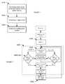
- FIG. 1is a flowchart diagram of the method of resetting a connected system.
- FIG. 2is a flowchart diagram of a first variation of the method.
- FIG. 3is a flowchart diagram of a second variation of the method.
- FIG. 4is a schematic representation of a first variation of the connected system.
- FIG. 5is a schematic representation of a second variation of the connected system.
- FIG. 6is a schematic representation of a lighting system interaction with an external power source, a primary remote device, and a secondary remote device.
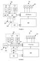
- FIG. 7is a schematic representation of a variation of the connected system installed in a recessed lighting fixture.
- FIG. 8is a cutaway view of an example of the lighting system.
- FIG. 9is a schematic representation of a first recorded power pattern 236 ′ substantially matching a power feature pattern.
- FIG. 10is a schematic representation of a mismatch between a second recorded power pattern 236 ′′ and a power feature pattern.
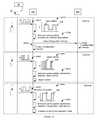
- FIG. 11is a schematic representation of a first example of the method, including initiating a configuration routine in response to detection of reset switch toggling.
- FIG. 12is a schematic representation of a second example of the method, including operating the connected system based on the configuration settings and operating the connected system based on operating instructions received from a remote device.
- FIG. 13is a schematic representation of a first, second, and third example of operating the connected system based on a pattern of external power provision, respectively.
- a connected system 100 capable of being reset without continuous power supplyincludes a reset switch 200 , reset memory 220 connected to the reset switch 200 , configuration memory 300 , and a control system 400 .
- the connected system 100can be a lighting system that additionally includes light emitting elements 500 , but can alternatively be any other suitable connected device (e.g., appliance).
- the lighting systemis substantially similar to the lighting system disclosed in U.S. application Ser. No. 14/512,669, filed 13 Oct. 2014, incorporated herein in its entirety by this reference.
- the lighting systemcan be any other suitable lighting system.
- the lighting systemfunctions to provide light based on a set of operating instructions received from a remote device, wherein the lighting system can connect to the remote device using a set of configuration settings stored by the lighting system.
- the connected system 100can additionally function as a communication transceiver (e.g., a WiFi repeater), a notification system (e.g., during emergencies), an immersive system (e.g., be responsive to an audio/video system), or perform any other suitable functionality.
- connected devicesparticularly connected appliances, require mechanisms to reboot (e.g., hard or soft reboot) and/or entirely reconfigure (e.g., factory reset or master reset) the device.
- Rebooting mechanismscan be required or desirable to troubleshoot the connected device, switch operating systems used by the connected device, clear corrupted or inadequately allocated memory, or for any other suitable purpose.
- Rebooting the connected system 100can include closing all pending programs and finalizes the input and output operations, or otherwise rebooting the system.
- Performing a master reset on the connected system 100can function to clear the configuration settings of the device to the default settings (e.g., such that the user can regain access to the connected device), remove a file or virus, clear memory space on the device, remove personal information from the device (e.g., prior to secondary sale or resale), remove data, settings, and/or applications on the device, or otherwise erase all or most of the customized information stored on the device.
- Resetting the connected system 100can include erasing all information aside from the default settings from the connected system 100 , or otherwise resetting the connected system 100 .
- a persistent reset mechanism(e.g., a reset mechanism that does not need to be powered during the reset trigger event) can be desirable in connected devices that are configured to be located in difficult-to-reach places (e.g., connected to difficult-to-reach power fixtures 40 ). This is due to the requirement that such connected appliances typically need to be removed from the power fixture 40 to access a reset switch 200 arranged along the device body. This problem can be particularly relevant to connected lighting systems (e.g., light bulbs), even more relevant to lighting systems that are independently operable (e.g., do not rely on a common hub), because lighting systems are not only difficult to reach when installed in ceiling fixtures, but must also be removed from the lighting fixture (e.g., particularly recessed lighting fixtures) to expose the reset mechanism for use.
- connected lighting systemse.g., light bulbs
- Some conventional reset mechanismscan be inadequate for such purposes, because they require the reset system to be powered to detect the reset trigger event (e.g., depression of a reset switch 200 ). Removal of the lighting system from the lighting fixture effectively disconnects the lighting system from power, which prevents such conventional reset mechanisms from detecting the trigger event and resetting the device.
- This inventionprovides such new and useful powerless resettable lighting system.
- the connected system 100includes a physical reset switch 200 , operable between a first and a second state, and non-volatile reset memory 220 configured to record the reset switch 200 state prior to system powering off (e.g., prior to power termination), and remember the reset switch 200 state while the system is unpowered.
- a master resetthe user can switch the reset switch 200 state to the opposing state.
- the connected system 100can compare the instantaneous reset switch 200 state with the prior state stored by the reset memory 220 .
- the systemcan initiate a master reset in response to the instantaneous reset switch 200 state differing from the stored switch state.
- the systemcan operate the system based on the stored configuration settings (e.g., operate in a normal operation state) in response to the instantaneous reset switch 200 state matching the stored switch state.
- the connected system 100operates in substantially the same manner as the first variation, and can additionally include rebooting the system in response to determination that the reset switch 200 state has been toggled (e.g., changed) while the connected system 100 is powered (e.g., while power is being supplied to the connected system 100 ).
- the connected system 100includes a toggle detector 230 configured to monitor patterns of power supplied to the connected system 100 (e.g., power cycling pattern).
- This variationcan be particularly relevant to connected systems 100 coupled to power fixtures 40 , wherein the power fixtures 40 are intermittently connected to a power grid based on the position of a power switch 50 (e.g., wall switch).
- the power supply patterns detected by the connected system 100can be established by a user toggling the power switch 50 or generated in any other suitable manner.
- the connected system 100can automatically initiate a master reset in response to detection of a first power supply pattern.
- the connected system 100can additionally or alternatively automatically initiate a reboot in response to detection of a second power supply pattern, different from the first power supply pattern.
- the connected system 100can additionally or alternatively operate in a different operation mode (e.g., control the light emitting elements 500 to emit light having a different set of light parameters) in response to detection of a third power supply pattern, different from the first and/or second power supply patterns.
- This variationcan function to simultaneously reset a plurality of connected systems 100 (e.g., all connected systems 100 whose power supply is controlled by the same power switch 50 ).
- the connected system 100can include any other suitable reset mechanism and be reset, rebooted, or otherwise configured in any other suitable manner.
- the connected system 100can be used with a power fixture, which functions to provide external power 32 to the connected system 100 , an example of which is shown in FIG. 6 .
- the power fixture 40can be a light fixture, such as a recessed light fixture (e.g., as shown in FIG. 7 ), surface-mounted light fixture, or any other suitable light fixture. More preferably, the power fixture 40 is a lightbulb socket (e.g., a conventional lightbulb socket), such as an Edison screw socket, bayonet socket bi-post socket, or any other suitable socket.
- the power fixture 40can be a power outlet, such as a USB port or a socket (e.g., a NEMA connector socket), or be any other suitable power supply mechanism connectable to an external power source 30 , such as a power grid or power system (e.g., generator system, solar powered system, etc.).
- the power fixture 40can supply power to the connected system 100 when power is supplied to the power fixture 40 , and does not supply power to the connected system 100 when the power fixture 40 is unpowered or disconnected from the external power source 30 .
- the power fixture 40can selectively control power provision to the connected system 100 , or operate in any other suitable manner.
- the power fixture 40can be electrically connected to a power switch 50 that functions to control power supply from the external power source 30 to the power fixture 40 .
- the power switch 50can be operable between a closed position, wherein power is supplied to the power fixture 40 , and an open position, wherein power supply to the power fixture 40 is terminated.
- the power fixture 40can be electrically connected to the external power source 30 when the power switch 50 is in the closed position, and can be electrically disconnected from the external power source 30 when the power switch 50 is in the open position.
- the power fixture 40can be otherwise selectively powered, unpowered, connected, or disconnected from the external power source 30 .
- the connected system 100can be used with a primary remote device 10 that functions to communicate information to and/or from the connected system 100 .
- the primary remote device 10can be associated with one or more identifiers.
- the identifierscan be unique identifiers (e.g., IP addresses), non-unique identifiers (e.g., user-set names), or be any other suitable identifier.
- the primary remote device 10can be associated with one or more credentials, wherein the credentials can be associated with one or more identifiers associated with the primary remote device 10 .
- the credentialscan include a password, encryption key (e.g., public and/or private), or any other suitable set of credentials.
- the primary remote device 10can be simultaneously connected to one or more connected systems 100 , wherein each connected system 100 can store an identifier and/or set of credentials associated with the primary remote device 10 in the customized configuration settings. Additionally or alternatively, a connected system 100 can connect one or more primary remote devices 10 (e.g., wherein the connected system 100 can function as a network hub or repeater).
- the primary remote device 10is preferably a networking device, such as a router (e.g., a wireless router), but can alternatively be a mobile device (e.g., a smart phone, tablet, laptop, computer, etc.), a second connected system 100 , or be any other suitable device remote (e.g., physically disconnected from) the connected system 100 .
- the connected system 100can be used with a secondary remote device 10 that functions to communicate information to and/or from the connected system 100 .
- the informationcan include operation instructions, primary remote device 10 connection information (e.g., identifiers and/or credentials), or any other suitable information.
- the secondary remote device 10can communicate information directly to the connected system 100 , communicate information indirectly to the connected system Dm (e.g., through the primary remote device 10 ), or be connected to the connected system 100 in any other suitable manner.
- the secondary remote device 10can be associated with one or more identifiers, such as social networking system identifiers (e.g., usernames), device identifiers, cellular service identifiers (e.g., phone number), connection identifiers (e.g., IP address), or any other suitable identifiers.
- the connected system 100can store the identifiers in the customized configuration settings, wherein connected system 100 control can be selectively permitted to secondary remote devices 10 having associated identifiers stored by the connected system 100 .
- the connected system 100 identifierscan be utilized in any other suitable manner.
- the secondary remote device 10can additionally or alternatively be associated with a set of credentials, wherein the credentials can be used by the connected system 100 to connect to the secondary remote device 10 .
- the secondary remote device 10can store a set of credentials associated with the connected system 100 , wherein connected system 100 control can be limited to secondary remote devices 10 storing the connected system 100 credentials.
- the secondary remote device 10can store or be associated with any other suitable information.
- the secondary remote device 10is preferably a mobile device (e.g., a smart phone, tablet, laptop, computer, etc.), but can alternatively be a networking device, such as a router (e.g., a wireless router), a second connected system 100 , or be any other suitable device remote (e.g., physically disconnected from) the connected system 100 .
- the reset switch 200 of the connected system 100functions to record a user action indicative of a desire to reset or reboot the connected system 100 .
- the reset switch 200is preferably a physical switch, but can alternatively be an electrical switch or digital switch.
- the reset switch 200is preferably operable between a first and a second state (e.g., an open and closed state, respectively), but can alternatively be operable in any other suitable number of states.
- the switchis preferably a toggle-type or non-momentary switch (e.g., a flip switch for continuous “on” or “off”), but can alternatively be a momentary-type switch (e.g., push for “on” or push for “off”) or any other suitable switch.
- the switchcan include a set of contacts actuated by an actuator.
- the actuatorcan be a toggle, a rocker, a rotary linkage, a push-button, or any other suitable mechanical linkage.
- the switchcan be non-biased or biased.
- the reset switch 200can be any other suitable mechanical switch.
- the reset switch 200can be an electronic switch, such as a relay, analog switch, power transistor, MOSFET, or any other suitable electronic switch operable in at least a first and second mode.
- the reset switch 200is preferably a single pole, single throw switch (SPST switch), but can alternatively be a single pole, double throw switch (SPDT switch), double pole, single throw switch (DPST switch), or have any other suitable contact arrangement.
- the reset switch 200is a binary switch.
- the reset switch 200is operable in two or more modes.
- the reset switch 200can be any other suitable switch.
- the reset switch 200is preferably arranged on or accessible through the system exterior, but can alternatively be arranged on or accessible through the system interior, system end, or through any other suitable portion of the system.
- the reset switch 200can be arranged along a longitudinal surface of the system, but can alternatively be arranged along a perimeter of the system (e.g., along an edge of a casing proximal the active surface of the connected system 100 ), an end of the system, or along any other suitable surface.
- the reset switch 200can be arranged such that the switch actuates in a direction having a vector substantially parallel to the system longitudinal axis, but can alternatively be arranged such that the actuation axis is substantially perpendicular to the system longitudinal axis or arranged in any other suitable configuration.
- the reset memory 220 of the connected system 100functions to record a state (position) of the reset switch 200 .
- the reset memory 220preferably records the reset switch 200 state while the connected system 100 or component thereof is powered (e.g., while power is supplied to the connected system 100 , light emitting elements 500 , control system 400 , and/or reset memory 220 ), but can additionally or alternatively record the reset switch 200 state while the connected system 100 or component thereof is unpowered, or record the reset switch 200 state at any other suitable time.
- the reset memory 220can record the reset switch 200 state in response to detection of a change in the reset switch 200 state, record the reset switch 200 state at a predetermined frequency, record the reset switch 200 state in response to the occurrence of a record event (e.g., power provision cessation, reset memory 220 interrogation, system initiation or startup, etc.), or record the reset switch 200 state at any other suitable time.
- the reset memory 220can record only the instantaneous reset switch 200 state, record both the instantaneous reset switch 200 state and one or more prior reset switch 200 states, record only the prior reset switch 200 state, or record any suitable reset switch 200 state.
- the reset memory 220is preferably non-volatile and retains its memory when power is turned off (e.g., when the reset memory 220 is unpowered), but can alternatively be volatile and maintain data only for as long as power is maintained.
- the reset memory 220can additionally include a separate power source that functions to supply power to the reset memory 220 when the remainder of the connected system 100 is unpowered.
- the reset memory 220can be powered by an on-board power source (e.g., the secondary power source 900 ) when the connected system 100 is disconnected from the external power source 30 .
- the latter variation of the reset memory 220can be unpowered and lose any stored information upon power provision cessation.
- non-volatile reset memory 220examples include flash memory, EEPROM, F-RAM, and MRAM, and can additionally include organic memory, mechanically addressed memory, or any other suitable non-volatile memory.
- the reset memory 220can include a CPU, microprocessor, or any other suitable computing system.
- the reset memory 220is preferably read/write memory, but can alternatively be read-only, write-only, or have any other suitable characteristic.
- the reset memory 220is preferably connected to the reset switch 200 , more preferably constantly connected to the reset switch 200 , but can alternatively be disconnected from the reset switch 200 , intermittently connected to the reset switch 200 , or otherwise connected to the reset switch 200 .
- the reset memory 220is preferably directly connected to the reset switch 200 , but can alternatively be indirectly connected to the reset switch 200 (e.g., through the control system 400 ) or otherwise connected to the reset switch 200 .
- the reset memory 220can be connected to one or more terminals of the reset switch 200 .
- the reset memory 220can be connected to the control system 400 , and/or to any other suitable connected system component.
- the configuration memory 300 of the connected system 100functions to store configuration settings.
- the configuration settingscan include remote device identifiers, credentials associated with the identifiers (e.g., one or more network identifiers and associated passwords, secondary remote device 10 identifiers, etc.), user settings (e.g., preferred operation parameter settings), user information (e.g., social networking system account identifier and password), applications, user-assigned identifier and/or credentials for the connected system 100 , or any other suitable information.
- the configuration settingscan be received from the primary remote device 10 , the secondary remote device 10 , a tertiary remote device (e.g., a server system associated with the connected system 100 ), automatically generated (e.g., learned based on historical settings), or otherwise determined.
- the configuration memory 300can additionally store default settings (e.g., factory settings), which can include the operating system, initialization sequence, default connected system 100 identifier, default connected system 100 credentials, and/or any other suitable default information.
- the configuration memory 300is preferably separate and distinct from the reset memory 220 , but can alternatively be a portion of the reset memory 220 , be part of the same memory as the reset memory 220 , or be related to the reset memory 220 in any other suitable manner.
- the configuration memory 300is preferably non-volatile memory, but can alternatively be volatile memory. In the latter variation, the volatile configuration memory 300 can be selectively powered in the manner discussed above for the volatile reset memory 220 , or can be powered in any other suitable manner.
- the volatile configuration memory 300is preferably powered asynchronously of the volatile reset memory 220 , but can alternatively be concurrently powered with the volatile reset memory 220 .
- the volatile configuration memory 300is preferably powered with a separate power source from the volatile reset memory 220 , but can alternatively be powered with the same power source as the volatile reset memory 220 .
- Examples of non-volatile configuration memory 300include flash memory, EEPROM, F-RAM, and MRAM, and can additionally include organic memory, mechanically addressed memory, or any other suitable non-volatile memory.
- the configuration memory 300can include a CPU, microprocessor, or any other suitable computing system.
- the configuration memory 300is preferably read/write memory, but can alternatively be read-only, write-only, or have any other suitable characteristic.
- the configuration memory 300is preferably electrically connected to the control system 400 , but can alternatively or additionally be electrically connected to the communication system 600 , the reset memory 220 , or any other suitable connected system component.
- the control system 400 of the connected system 100functions to control connected system 100 operation (e.g., connected system component operation).
- the control system 400can operate the connected system 100 in a configured mode (normal mode), wherein the connected system 100 is operated based on the configuration settings.
- the control system 400can operate the light emitting elements 500 , the communication system 600 , or any other suitable connected system component based on the configuration settings.
- the control system 400can control the communication system 600 (e.g., wireless communication system 600 ) to connect to a remote device based on the configuration settings, can receive instructions from the remote device through the communication system 600 , and can control operation of the light emitting elements 500 based on the instructions.
- control system 400can operate the connected system 100 in the normal mode in any other suitable manner.
- the control system 400can additionally or alternatively operate the connected system 100 in a reset mode (configuration mode), wherein the control system 400 erases stored configuration settings from the configuration memory 300 and executes an initialization routine or operates the connected system 100 based on the default settings.
- the control system 400can additionally or alternatively operate the connected system 100 in any other suitable mode.
- the control system 400can additionally function to select the operation mode. For example, the control system 400 can select the configuration mode in response to the stored reset switch 200 state differing from the instantaneous reset switch 200 state or in response to receipt of a power cycle substantially matching a predetermined power cycling pattern, and otherwise select the normal mode.
- the control system 400can additionally function to distribute or otherwise control power provision to connected system components, detect whether external power is being provided to the connected system 100 , or perform any other suitable functionalities.
- the control system 400can be electrically connected to the reset switch 200 , the reset memory 220 , the configuration memory 300 , the light emitting elements 500 , the communication system 600 , and/or any other suitable connected system component.
- the control system 400can be one or more CPUs, microprocessors, microcontrollers, or any other suitable set of computing units.
- the connected system 100can be a lighting system and include a set of light emitting elements 500 .
- the light emitting elements 500function to emit light having properties (e.g., intensity, wavelength, saturation, color temperature, etc.) determined by the control system 400 .
- the lighting systemcan include one or more light emitting elements 500 .
- the light emitting elements 500can be arranged in an array (e.g., rectangular array), a circle, about a system perimeter, in concentric circles, randomly, or distributed in any other suitable configuration.
- the light emitting elementcan be a light emitting diode (LED), OLED, an incandescent bulb, an RF diode, or any other suitable light emitting element.
- the systemcan include any other suitable EM wave emitter (e.g., electromagnet, ultrasound emitter, etc.).
- the light emitting elementcan emit visible light, RF, IR, UV, or light at any other suitable spectrum.
- the set of light emitting elements 500cooperatively emit at least 500 lumens. However, the set of light emitting elements 500 can cooperatively emit 750 lumens, 1,000 lumens, or any other suitable number of lumens.
- the systempreferably includes at least 10 light emitting elements 500 or light emitting element clusters (e.g., each cluster including one or more light emitting diodes configured to emit different wavelengths of light), but can alternatively include a single light emitting element or cluster, at least 30 light emitting elements 500 or clusters, or any other suitable number of light emitting elements 500 .
- the connected system 100can additionally or alternatively include a communication system 600 , which functions to communicate information between the control system 400 and a device.
- the communication system 600is preferably a wireless communication system 600 , wherein the device is a remote device (e.g., the primary or secondary device), but can alternatively be a wired communication system 600 (e.g., powerline communication, Ethernet communication, etc.), wherein the device is a proximal or physically connected device.
- the connected system 100can include one or more communication systems 600 .
- the wireless communication system 600can be a transmitter, a receiver, a transceiver, repeater, or any other suitable wireless communication system 600 .
- the wireless communication system 600can simultaneously be connected to one or more remote devices (e.g., one or more secondary and/or primary devices), be configured to connect to a single remote device, or be configured to connect to any other suitable number of devices.
- the wireless communication system 600can connect to the devices using the configuration settings (e.g., using the credentials stored in the configuration settings), default settings, or connect to the devices in any other suitable manner.
- the wireless communication system 600preferably automatically connects to the remote device, but can alternatively or additionally connect to the remote device in response to receipt of a notification from a second remote device, detection of a predetermined power cycling pattern, or in response to any other suitable trigger event. Additionally or alternatively, the remote device can connect to the wireless communication system 600 using credentials broadcast by the wireless communication system 600 , credentials stored by the remote device (e.g., wherein the credentials for the lighting system were set by a remote device), or connect to the wireless communication system 600 in any other suitable manner.
- the wireless communication system 600can send information to a targeted endpoint (e.g., a single device, a specified set of devices), broadcast information, function as a router or WLAN provider, or have any other suitable functionality.
- the wireless communication system 600can receive information from a single endpoint, multiple endpoints (e.g., wherein the endpoints are associated or unassociated with encryption keys or other credentials), or from any other suitable information source.
- the wireless communication system 600can be a short-range communication system 600 or long range communication system 600 .
- Examples of short-range communication systems 600 that can be usedinclude Bluetooth, BLE, RF, IR, and ultrasound, but any other suitable communication system 600 can be included.
- the light emitting elements 500can function as the wireless communication system 600 , wherein information can be controlled through light modulation or any other suitable methodology.
- Examples of long-range communication systems 600 that can be usedinclude WiFi, cellular, and Zigbee, but any other suitable communication system 600 can be included.
- the systemcan include one or more communication systems 600 .
- the connected system 100can additionally or alternatively include an external power connector 700 that functions to electrically connect the connected system 100 to an external power source 30 .
- the external power connector 700can be electrically connected to the control system 400 , the reset memory 220 , the configuration memory 300 , the wireless communication system 600 , secondary power source 900 , and/or any other suitable connected system component.
- the external power connector 700is directly electrically connected to the control system 400 , wherein the control system 400 conditions and/or distributes power to the remaining connected system components.
- the external power connector 700is electrically connected to individual connected system components.
- the connected system 100can be wired in any other suitable manner.
- the external power connector 700can be a lightbulb base (e.g., Edison screw base, bayonet style base, bi-post connector, wedge base, lamp base, etc.), a plug, socket, power connector (e.g., AC power plug, DC connector, NEMA connector, etc.), or any other suitable form of electrical connector.
- the external power connector 700is preferably arranged along the exterior of the connected system 100 , but can alternatively be recessed within the body of the connected system 100 .
- the external power connector 700is preferably arranged along an end of the connected system 100 (e.g., along an end distal the light emitting elements 500 in a lighting system), but can alternatively be arranged along a side of the connected system 100 or along any other suitable portion of the connected system 100 .
- the connected system 100can additionally or alternatively include a connection indicator 800 that functions to detect external power connector 700 connection with a power fixture 40 , as shown in FIG. 8 .
- the connection indicator 800can be operable between a connected mode when the external power connector 700 is connected to a power fixture 40 and a disconnected mode when the external power connector 700 is disconnected from the power fixture 40 , or can be operable between any other suitable set of modes.
- the connection indicator 800can be a physical switch (e.g., biased in the open direction associated with the disconnected mode when physically decoupled from the power fixture 40 ), electromagnetic switch (e.g., a ferrous material or wire winding configured to detect an applied electromagnetic field when the external power connector 700 is connected to the power fixture 40 , etc.), or be any other suitable detection mechanism.
- the connection indicator 800can be arranged proximal the external power connector 700 , along the external power connector 700 (e.g., along the side or end of the external power connector 700 ), distal the external power connector 700 , or be arranged in any other
- the connected system 100can additionally or alternatively include a secondary power source 900 that functions to provide power to the connected system components.
- the secondary power source 900can additionally function to condition external power for connected system components, supply power for standby operation (e.g., power a battery management system when the connected system 100 is otherwise unpowered), or perform any other suitable functionality.
- the secondary power source 900provides power to the connected system components when the connected system 100 is electrically connected to the external power source 30 .
- the secondary power source 900provides power to all connected system components when power from the external power source 30 has ceased (e.g., when the connected system 100 is physically disconnected from the power fixture 40 , when power provision from the external power source 30 to the fixture is terminated, etc.).
- the secondary power source 900provides power to a select set of connected system components (e.g., the reset memory 220 ) when power from the external power source 30 has ceased (e.g., wherein the secondary power source 900 is only connected to the select set of connected system components or is connected to more than the select set of connected system components).
- the secondary power source 900provides power to the connected system components in response to the occurrence of a trigger event, such as receipt of an emergency signal from a remote device, determination that external power provision ceased but the power switch 50 is in the open position, or any other suitable trigger event.
- the secondary power source 900can be electrically connected to all connected system components, a subset of connected system components, or any other suitable set of connected system components.
- the secondary power source 900is preferably electrically connected to and charged by the external power connector 700 , but can alternatively be electrically disconnected and/or substantially isolated from the external power connector 700 .
- the secondary power source 900can be substantially permanently connected to the connected system components, selectively connected to the connected system components, or otherwise connected to the connected system components.
- the connected system 100can include one or more secondary power sources 900 , wherein multiple secondary power sources 900 can be connected to the same connected system components or to different connected system components. Alternatively, the connected system 100 can lack or exclude secondary power sources 900 .
- the secondary power source 900can be a secondary (rechargeable) battery (e.g., having lithium chemistry, nickel chemistry, cadmium chemistry, magnesium chemistry, platinum chemistry, etc.), a fuel cell system, a solar cell system, a piezoelectric system, or any other suitable source of power.
- a secondary (rechargeable) batterye.g., having lithium chemistry, nickel chemistry, cadmium chemistry, magnesium chemistry, platinum chemistry, etc.
- a fuel cell systeme.g., a fuel cell system, a solar cell system, a piezoelectric system, or any other suitable source of power.
- the connected system 100can additionally or alternatively include toggle detector 230 that functions to record (e.g., count) a recorded power pattern 236 reflecting the number of times external power provision to the connected system 100 has been cycled (e.g., turned on and off, switched between high and low power, etc.).
- the recorded power pattern 236can be subsequently analyzed in light of a set of stored power feature patterns 234 , wherein a connected system operation mode can be selected based on whether the recorded power pattern 236 substantially matches a power feature pattern 234 .
- the recorded power pattern 236can be otherwise used.
- the toggle detector 230is preferably electrically connected to the external power connector 700 , but can alternatively or additionally be electrically connected to the control system 400 or any other suitable connected system component.
- the recorded power pattern 236is preferably recorded in the reset memory, but can alternatively be recorded in any other suitable memory.
- a cycle count stored in the reset memory 220 or any other suitable memorycan be increased each time the external power is provided to the system, each time the external power is removed from the system, each time the external power is provided then removed within a predetermined period of time, or in response to any other suitable trigger event.
- the recorded power pattern 236can be stored with a timestamp (e.g., universal or relative) or stored without a timestamp.
- the recorded power pattern 236can be erased at a predetermined frequency (e.g., every 10 minutes), erased in response to the occurrence of an erase event (e.g., execution of a configuration routine), be persistent, or edited in any other suitable manner.
- the toggle detector 230includes a winding connected to the external power connector 700 or a transistor (e.g., MOSFET) connected therebetween, a set of resistor voltage dividers, a rectifier diode, and a filter capacitor.
- the diodecan rectify the AC voltage of the power from the external power connector 700
- the resistor voltage dividerscan divide the rectified bias AC voltage
- the capacitorcan filter out voltage ripple.
- the diode, voltage divider, and capacitorcan cooperatively monitor whether bias AC voltage is applied across the winding, wherein bias AC voltage will be applied when external power is supplied to the external power connector 700 , and bias AC voltage will not be applied to the winding when the external power connector 700 is unpowered.
- the toggle detector 230can include a rising edge detector and/or falling edge detector connected to the external power connector 700 .
- the toggle detector 230can include any other suitable circuitry configured to determine when external power is provided and/or removed from the connected system 100 .
- the connected system 100can additionally include a set of sensors 520 that function to measure ambient environment parameters, system parameters, or any other suitable set of parameters.
- parameters that can be measuredinclude ambient light (e.g., visible light, IR, etc.), ambient sound (e.g., audio, ultrasound, etc.), ambient temperature, ambient pressure, geographic location, system temperature, system voltage, system current, system operating time, system position, and system acceleration, but any other suitable parameter can be measured.
- the connected devicecan include one or more sensors or types of sensors.
- the set of sensors 520can include a light sensor (e.g., camera), sound sensor (e.g., microphone, ultrasound sensor), accelerometer, gyroscope, GPS, or any other suitable sensor.
- the method of resetting the connected systemincludes receiving power at the connected system from a power source S 100 , detecting a reset trigger event S 200 , and initiating a configuration routine in response to detection of the reset trigger event S 300 .
- the methodfunctions to reset the connected system without receiving reset instructions from a remote device.
- the methodis preferably performed by the system 100 disclosed above, but can alternatively be performed by any other suitable connected system.
- the methodincludes receiving power at the connected system from a power source S 100 , interrogating reset memory for a stored reset switch state S 220 , determining an instantaneous reset switch state S 222 , comparing the stored reset switch state with the instantaneous reset switch state S 224 , operating the connected system in the reset mode by initiating a configuration routine in response to the stored reset switch state differing from the instantaneous reset switch state S 300 , and operating the connected system in the configured mode in response to the stored reset switch state matching the instantaneous reset switch state S 400 .
- the methodcan detect the reset trigger event even though the system is disconnected from power when the reset switch state is switched. This can enable a user to trigger a master reset of the system by removing the connected system from the power fixture such that the system is unpowered by external power, switching the reset switch state, reconnecting the connected system to the power fixture, and supplying external power to the connected system.
- the methodincludes receiving power at the connected system from a power source S 100 , detecting a pattern of external power supply to the connected system within a predetermined time period S 240 , and operating the connected system in the reset mode by initiating a configuration routine in response to the detected pattern substantially matching a predetermined reset pattern S 300 , and operating the connected system in the configured mode in response to the stored reset switch state substantially differing from the predetermined reset pattern S 400 .
- the methodcan enable the user to substantially simultaneously reset or reboot a set of connected systems (e.g., one or more connected systems) electrically connected to the same power circuit without physically accessing each connected system.
- the methodcan include any other suitable reboot or reset method.
- Receiving power at the connected system S 100 from a power sourcefunctions to initiate trigger event monitoring.
- Receiving power at the connected systemcan additionally function to provide power to the connected system components.
- the power sourceis preferably an external power source (e.g., a power grid or power system), but can alternatively be an internal power source (e.g., the secondary power source) or any other suitable power source.
- the internal power sourcecan power the connected system components only when the connected system is physically connected to an external power source, power the connected system components irrespective of connected system physical or electrical connection to the external power source, or supply power to the connected system components at any other suitable time.
- Receiving powercan include detecting applied power at the connected system. Detecting power at the connected system can include determining that the current through a connection system component exceeds a baseline current, determining that the voltage across a connection system component exceeds a baseline voltage, or sensing supplied power in any other suitable manner.
- Receiving power at the connected system from a power source S 100can include detecting initial power receipt at the connected system S 110 .
- Detecting initial power receiptcan include detecting the rising edge of a power curve with a rising edge detector.
- Detecting initial power receiptcan additionally or alternatively include detecting a pattern of power termination then power supply.
- Detecting power terminationcan include detecting a falling edge of the power curve, determining that the current through a connection system component falls below a current threshold, determining that the voltage across a connection system component falls below a baseline voltage, or determining power cessation or supplied power drop in any other suitable manner.
- Detecting supplied powercan include detecting the rising edge of a power curve, determining that the current through a connection system component exceeds a baseline current, determining that the voltage across a connection system component exceeds a baseline voltage, or determining supplied power in any other suitable manner.
- initial power receiptcan be detected in any other suitable manner.
- Receiving power at the connected system S 100can additionally include detecting physical system connection to an external power source. Detecting physical connected system connection to an external power source can be used to determine whether the secondary power source should be controlled to power the connected system components, or be used in any other suitable manner.
- the secondary power sourcecan be electrically connected to the system components in response to physical connected system connection to the external power source.
- the secondary power sourcecan be electrically disconnected from the system components in response to physical connected system connection to the external power source.
- the physical system connection detectioncan be otherwise used.
- Detecting physical system connection to an external power sourcepreferably includes detecting physical system connection to a power fixture, but can alternatively include detecting external power provision to the connected system or be detected in any other suitable manner.
- detecting physical system connection to an external power sourceincludes detecting actuation of the connection indicator (e.g., depression of a connection indicator switch, etc.).
- detecting physical system connection to an external power sourceincludes detecting completion or closure of a circuit that is open when the system is disconnected from the power fixture, and closed when the system is connected to the power fixture.
- connection indicatore.g., depression of a connection indicator switch, etc.
- detecting physical system connection to an external power sourceincludes detecting completion or closure of a circuit that is open when the system is disconnected from the power fixture, and closed when the system is connected to the power fixture.
- physical system connection to an external power sourcecan be otherwise detected.
- Receiving power at the connected system S 100can additionally include detecting physical lighting system disconnection from the external power source. Detecting physical lighting system disconnection from an external power source can be used to determine whether the secondary power source should be controlled to power the connected system components, or be used in any other suitable manner.
- the secondary power sourcecan be electrically connected to the system components in response to physical connected system disconnection from the external power source.
- the secondary power sourcecan be electrically disconnected from the system components in response to physical connected system disconnection from the external power source.
- the physical system disconnection detectioncan be otherwise used.
- Detecting physical system disconnection from an external power sourcepreferably includes detecting physical system disconnection from a power fixture, but can alternatively include detecting cessation of external power provision to the connected system, or be detected in any other suitable manner.
- detecting physical system disconnection from an external power sourceincludes detecting actuation of the connection indicator (e.g., depression of a connection indicator switch, etc.).
- detecting physical system disconnection from an external power sourceincludes detecting the opening or disconnection of a circuit that is closed when the system is connected to the power fixture.
- physical system disconnection from an external power sourcecan be otherwise detected.
- Receiving power at the connected system S 100can additionally include detecting termination of power supplied from the power source S 120 .
- the power supply termination or disconnectioncan be detected for a connected system component (e.g., the reset memory, the configuration memory, the control system, the communication system, etc.), a set of connected system components, the entire connected system, or for any other suitable combination of connected system components.
- the power sourceis preferably the external power source, but can alternatively or additionally be the secondary power source or any other suitable power source.
- Receiving power at the connected system S 100can additionally include storing a reset switch state prior to power supply termination in the reset memory S 700 , which functions to store the reset switch state prior to system power down, such that the reset switch state can be retrieved and compared after the system is powered.
- the reset switch stateis preferably determined and initially stored when the connected system is powered, but can alternatively be determined and/or stored when the connected system is unpowered. In one example, the reset switch state can be determined and stored only when external power is supplied to the connected system.
- the reset switch stateis preferably retained (e.g., stored) while the reset memory and/or connected system is unpowered, wherein the reset memory is preferably non-volatile memory or be volatile memory including a power source, but can alternatively be erased once the reset memory is unpowered.
- the reset switch statecan be stored in response to the occurrence of a storage event or stored at any other suitable time.
- the storage eventcan be the satisfaction of a predetermined period of time (e.g., wherein the reset switch state is determined and/or stored at a predetermined frequency), the comparison of the instantaneous reset switch state and a prior switch state, a reset switch state change, receipt of a state storage request, the execution of a configuration routine, or be any other suitable storage event.
- Detecting a reset trigger event S 200functions to identify when the reset or reboot routine should be executed.
- the reset trigger eventis preferably detected by the control system, but can alternatively be detected by a dedicated trigger event detection module, or by any other suitable component.
- the reset trigger eventis the determination that a prior reset switch state is different from the instantaneous switch state.
- the determinationcan be made in response to detection of a reset switch state change (e.g., the pulse received from reset switch, when the system is powered), in response to a comparison between the instantaneous reset switch state and a prior reset switch state stored in the reset memory (e.g., wherein the prior reset switch state was stored a predetermined period of time beforehand, stored before the system was powered off then powered on, or stored at any other suitable time), or determined in any other suitable manner.
- a reset switch state changee.g., the pulse received from reset switch, when the system is powered
- a prior reset switch state stored in the reset memorye.g., wherein the prior reset switch state was stored a predetermined period of time beforehand, stored before the system was powered off then powered on, or stored at any other suitable time
- the methodcan include interrogating the reset memory for the stored reset switch state S 220 , determining an instantaneous reset switch state S 222 , and comparing the stored reset switch state and the instantaneous reset switch state S 224 , but can alternatively include any other suitable process.
- Interrogating the reset memory for the stored reset switch state S 220functions to determine the prior reset switch state.
- the prior reset switch statecan be the reset switch state before initial power supply to the system was detected, the state that the reset switch was in the last time the reset switch state was checked, or be the reset switch state at any other suitable time.
- the stored reset switch stateis preferably retrieved or referenced from the reset memory, but can alternatively be requested (e.g., received in response to a sent request) or otherwise determined.
- the reset memoryis preferably interrogated for the prior switch state during system initiation (e.g., power up, in response to initial power receipt, etc.), but can alternatively be interrogated in response to power receipt, at a predetermined frequency, in response to a storage trigger event, or interrogated at any other suitable time.
- the reset memoryis preferably interrogated by the control system, but can alternatively be interrogated by any other suitable component.
- Determining an instantaneous reset switch state S 222functions to determine the current reset switch state for comparison with the prior reset switch state.
- the instantaneous reset switch stateis preferably determined by the control system (e.g., by interrogating the reset switch), but can alternatively be determined by any other suitable system.
- the instantaneous reset switch stateis preferably determined from the reset switch, but can alternatively be determined (e.g., retrieved or received) from an intermediary reset switch system or from any other suitable source.
- the instantaneous reset switch statecan be received from the reset memory, wherein the reset memory stores both the last reset switch state (e.g., instantaneous reset switch state) and the prior reset switch state.
- the instantaneous reset switch statecan be otherwise determined.
- the instantaneous reset switch stateis preferably determined during system initiation (e.g., power up, in response to initial power receipt, etc.), but can alternatively be determined in response to power receipt, at a predetermined frequency, in response to a storage trigger event, or determined at any other suitable time.
- Comparing the stored reset switch state and the instantaneous reset switch state S 224functions to determine whether there was a change in the reset switch state.
- comparing the prior and instantaneous reset switch statescan function to determine whether the reset switch was toggled while the connected system was unpowered.
- the prior and instantaneous reset switch statesare preferably compared by the control system, but can alternatively be compared by the reset memory, reset switch system, or any other suitable system.
- the prior and instantaneous reset switch statesare preferably compared during system initiation (e.g., power up, in response to initial power receipt, etc.), but can alternatively be compared in response to power receipt, at a predetermined frequency, in response to a storage trigger event, or compared at any other suitable time.
- Comparing the prior and instantaneous reset switch statescan include determining the difference between the prior and instantaneous reset switch states, estimating, measuring, noting the similarity or dissimilarity between the stored and instantaneous states, or otherwise comparing the prior and instantaneous reset switch states.
- the comparisoncan additionally function to trigger different routines.
- a configuration routinecan be initialized in response to a mismatch between the prior and current reset switch states, while a configured or normal routine can be initialized in response to a match between the prior and current reset switch states.
- the comparisoncan be power transition dependent or independent.
- a master reset routinecan be initialized in response to a mismatch between the prior and instantaneous reset switch states, wherein the prior and instantaneous reset switch states bound an initial power provision event
- a restart routinecan be initialized in response to mismatch between the prior and instantaneous reset switch states, wherein the prior and instantaneous reset switch states do not bound an initial power provision event
- a configured or normal routinecan be initialized in response to a match between the prior and current reset switch states.
- a master reset routinecan be initialized in response to a mismatch between the prior and instantaneous reset switch states, irrespective of whether the prior and current reset switch states bound an initial power provision event, while a configured or normal routine can be initialized in response to a match between the prior and current reset switch states.
- the comparisoncan be time- or history-independent, or be time- or history-dependent.
- the master reset routinecan be initialized each time the prior and current reset switch states differ.
- the master reset routinecan be initialized when the prior and current reset switch states differ, in addition to the prior reset switch state remaining substantially constant for a predetermined period of time (e.g., based on timestamps associated with the prior reset switch state), while the master reset routine will not be initialized when the prior and current reset switch states differ, but the prior reset switch state had changed within the predetermined period of time.
- the master reset routinecan be initialized in response to determination that the prior and current reset switch states differ, and that an initial power provision event occurred between the timestamps associated with the prior and current reset switch states, respectively, while a restart routine can be initialized in response to determination that the prior and current reset switch states differ, but an initial power provision event did not occur between the associated timestamps.
- the comparisoncan trigger any other suitable system operation.
- the reset trigger eventis the determination that a pattern of power provision to the connected system substantially meets a predetermined reset pattern.
- the power monitored for the patternis preferably external power, but can alternatively be internal power (e.g., supplied by the secondary power source).
- the systemcan determine that a system on/off pattern substantially matches a predetermined on/off pattern associated with a reset routine.
- the power provisionis preferably monitored while the connected system is substantially continuously physically connected to the power fixture (e.g., the connection indicator indicates that the connected system is connected to the power fixture), but can alternatively be monitored when the connected system is intermittently physically connected to the power fixture (e.g., wherein the connected system is physically removed from the power fixture in between consecutive power cycle feature recordations), or monitored over any other suitable time period.
- This variationcan include recording power transition events S 242 , analyzing the pattern of power transition events S 244 , and performing one of a set of operations based on the power transition event pattern S 246 , but can alternatively include any other suitable process.
- Recording the power transition events S 242functions to monitor a feature of the power cycle (power feature pattern), and can include increasing a counter in response to detection of a rising or falling edge of a power curve, increasing a counter in response to detection of applied voltage across the system or current through the system, or monitoring the power transition events in any other suitable manner.
- the power transition eventscan be detected by the toggle detector, control system, or other system.
- the power transition eventscan be recorded by the reset memory, the control system, configuration memory, or any other suitable memory.
- Analyzing the pattern of power transition events S 244can include comparing the recorded pattern with a predetermined pattern, overlaying the recorded pattern over a predetermined pattern, or otherwise analyzing the pattern of power transition events.
- a recorded patternpreferably substantially matches a predetermined pattern when the recorded pattern falls within a predetermined percentage or standard deviation of the predetermined pattern (e.g., an example of which is shown in FIG. 9 ), and does not match the predetermined pattern when the recorded pattern deviates beyond a threshold deviation from the predetermined pattern (e.g., an example of which is shown in FIG. 10 ), but can alternatively substantially match or not match the predetermined pattern in any other suitable manner.
- the recorded patterncan be analyzed for one or more predetermined patterns.
- Performing one of a set of operations based on the power transition event pattern S 246can include selecting an operation from a set of predetermined operations based on the determined pattern and controlling the system to execute the selected operation, examples of which are shown in FIG. 13 .
- the operationis preferably selected and/or performed by the control system, but can alternatively be selected and/or performed by any other suitable component.
- a different power transition event patternis preferably associated with each operation, wherein different power transition event patterns preferably have different pattern parameters.
- Pattern parameterscan include the duration of the pattern (e.g., how long the power transition events should be monitored for), a minimum, maximum, average, or mean duration of time between each power transition event (e.g., the duration that the external power should be supplied, the duration that the external power should be shut off, etc., such as a pattern including power provision for 30 seconds, power shutoff for 30 seconds, and power provision for 30 seconds), a power transition event frequency, a power transition event amplitude (e.g., patterns in the voltage or current magnitude supplied to the system), or include any other suitable parameter.
- the patterns associated with each operationcan be determined by a manufacturer, received from a remote device (e.g., wherein the pattern is associated by a user), received from the external power source in response to receipt of a pattern association notification, or determined in any other suitable manner.
- the connected systemrecords a pattern of intermittent external power supply to the connected system, compares the recorded pattern to a predetermined power cycling pattern, and initializes the reset routine in response to the recorded power provision pattern substantially matching the predetermined power cycling pattern.
- the connected systemrecords a pattern of intermittent external power supply to the connected system.
- the control systeminitializes the reset routine in response to the recorded pattern substantially matching a first predetermined power cycling pattern, initializes a restart routine in response to the recorded pattern substantially matching a second predetermined power cycling pattern different from the first predetermined power cycling pattern, and operates the connected system in a different operation mode in response to the recorded pattern substantially matching a second predetermined power cycling pattern different from the first and second predetermined power cycling patterns.
- the different operation modecan be a different lighting scene wherein the light emitting elements emit light having a different parameter from that previously emitted.
- the reset or reboot trigger eventcan be the receipt of a notification (e.g., a reset notification, reboot notification, etc.) or other communication from a remote device.
- the reset or reboot trigger eventcan be the detection of a signal received at a sensor.
- the trigger eventcan include detecting an audio pattern substantially matching a predetermined audio pattern (e.g., received at a microphone), a sound pattern substantially matching a predetermined sound pattern (e.g., received at a transducer or other sound sensor), a vibration pattern substantially matching a predetermined vibration pattern (e.g., a tapping or knocking pattern on the connected system, received at a vibration sensor), a light pattern substantially matching a predetermined light pattern, or detection of any other suitable signal input associated with the reset or reboot operation.
- the reset or reboot trigger eventcan be the detection of an error in system operation.
- the reset trigger eventcan be any other suitable event indicative of a request to reset the system.
- Initiating a reset routine (configuration routine) S 300functions to perform a master reset on the system.
- the reset routineis preferably initiated and performed by the control system, but can alternatively be initiated and/or performed by the communication system or any other suitable component.
- the reset routineis preferably initiated in response to trigger event detection, but can alternatively be performed at any other suitable time.
- Performing the reset routinecan include erasing information from the connected system and initiating an initializing routine. Erasing information from the connected system can include erasing all information on the device except the default settings, erasing the configuration settings from the configuration memory, or erasing any other suitable information from the system.
- the initializing routinefunctions to enable device connection to the connected system.
- the initializing routineis preferably performed by the control system, but can alternatively be performed by any other suitable component.
- the initializing routinecan be automatically performed in response to determination that the prior reset switch position differs from the instantaneous reset switch position, in response to determination that the power cycling pattern substantially matches a predetermined pattern, performed as part of the configuration routine, performed in response to determination that no configuration settings are stored, performed in response to power provision to the connected system after the configuration settings have been erased, or be performed at any other suitable time.
- Performing the initializing routinepreferably includes operating the system based on the default settings stored by the system, but can alternatively or additionally include retrieving default settings from a remote system (e.g., remote server system) and operating the system based on the retrieved settings, or operating the system in any other suitable manner.
- a remote systeme.g., remote server system
- performing the initializing routineincludes broadcasting a default system identifier and/or credentials, receiving a connection request from a remote device (e.g., secondary remote device, such as a user device), wherein the connection request can include the broadcast information (e.g., default system identifier and/or credentials), verifying the received information, sending a connection verification to a remote device, wherein the remote device can be the remote device from which the connection request was received or a different remote device, receiving a set of configuration settings, and storing the set of configuration settings.
- a remote devicee.g., secondary remote device, such as a user device
- the connection requestcan include the broadcast information (e.g., default system identifier and/or credentials)
- verifying the received informationsending a connection verification to a remote device, wherein the remote device can be the remote device from which the connection request was received or a different remote device, receiving a set of configuration settings, and storing the set of configuration settings.
- the set of configuration settingscan include a set of remote device identifiers and respective credentials, wherein the set of remote device identifiers and respective credentials are preferably primary remote device identifiers and credentials, but can alternatively be secondary remote device identifiers, secondary remote device credentials, secondary connected system identifiers, secondary connected system credentials, and/or be any other suitable set of configuration settings.
- the configuration settingsare preferably received after the connection verification is sent, wherein the remote device receives the connection verification and prompts the user for configuration setting entry.
- the remote devicecan automatically determine the configuration settings (e.g., retrieve the configuration settings from remote device memory) and send the configuration settings to the connected system.
- the configuration settingscan be otherwise obtained.
- Performing the initializing routinecan additionally include providing a visual or audio indicator to a user S 320 , which functions to notify the user that the connected system is undergoing an initializing routine.
- the visual indicatorcan include controlling the light emitting elements to display a reset notification sequence including predetermined light pattern (e.g., red, green, blue, white).
- the audio indicatorcan include controlling a speaker to emit a predetermined tone or set of tones.
- the connected systemcan broadcast a reset notification to remote devices.
- the systemcan be initialized in any other suitable manner.
- the methodcan additionally include operating the connected system based on the configuration settings S 400 , which functions to operate the connected system based on user preferences.
- the connected systemis preferably operated based on the configuration settings (e.g., in the normal mode) by the control system, but can alternatively be performed by any other suitable component.
- the connected systemcan be automatically operated based on the configuration settings in response to determination that the trigger event has not occurred, but can be operated based on the configuration settings at any other suitable time.
- the connected systemcan be operated based on the configuration settings in response to determination that the prior reset switch position substantially matches the instantaneous reset switch position, in response to determination that the power cycling pattern differs from a predetermined pattern, in response to determination that configuration settings are stored by the connected system, in response to power provision to the connected system, in response to determination of a trigger event non-occurrence, or operated in the normal mode at any other suitable time.
- Operating the connected system based on the configuration settingscan include operating the connected system according to the configuration settings (e.g., operating the light emitting elements according to instructions or parameter settings stored in the configuration settings), operating the connected system using the configuration settings (e.g., connecting to a remote device using an identifier and credentials stored in the configuration settings), or operating the connected system based on the configuration settings in any other suitable manner.
- the configuration settingse.g., operating the light emitting elements according to instructions or parameter settings stored in the configuration settings
- operating the connected system using the configuration settingse.g., connecting to a remote device using an identifier and credentials stored in the configuration settings
- operating the connected system based on the configuration settingsin any other suitable manner.
- operating the lighting system based on the configuration settings S 400can include retrieving operating instructions from the configuration settings and controlling the light emitting elements according to the operating instructions.
- operating the lighting system based on the configuration settings S 400can include connecting the connected system to a remote device (e.g., primary remote device or secondary remote device) using the respective remote device identifier and credentials (e.g., encryption keys) stored in the configuration settings, receiving operating instructions from the remote device S 800 , and controlling system operation based on the operating instructions S 900 .
- This methodcan be performed by the control system using the communication system, or be performed by any other suitable component.
- the connected systemcan simultaneously connect to a single remote device, multiple remote devices, or any suitable number of remote devices.
- Controlling system operation based on the operating instructionscan include controlling light emitting element operation (e.g., controlling the emitted light parameters), controlling communication system operation (e.g., controlling which remote devices the system connects to, communication system connection permissions, etc.), controlling data processing (e.g., controlling data compression, encryption, transmission channels, endpoints, etc.), or controlling any other suitable aspect of connected system operation based on the information received from the remote device.
- a second set of configuration settingscan additionally or alternatively be received from the remote device, wherein the second set of configuration settings can overwrite the first set of configuration settings or be stored with the first set of configuration settings.
- operating the lighting system based on the configuration settingscan include connecting the connected system to a wireless router using credentials stored in the configuration settings, receiving operation instructions from one or more secondary remote devices connected to the network supported by the wireless router, and controlling the set of light emitting elements or any other suitable output based on the operation instructions.
- the operation instructionscan be directly received from the secondary remote devices connected to the network, or can be indirectly received from the secondary remote devices connected to the network through the router.
- the operation instructionscan be sent by the secondary remote devices to the primary remote device (the router) in association with a connected system identifier identifying the connected system and/or with connected system credentials associated with the connected system.
- the operation instructionscan be or sent to the primary remote device without identifiers, credentials, or other information associated with the connected system.
- the primary remote devicepreferably sends the operation instructions to the connected system identified by the connected system identifier or associated with the connected system credentials, but can alternatively broadcast the operation instructions to the set of connected systems connected to the primary remote device, wherein the connected system associated with the identifier or credentials can receive and unpack the operation instructions, retrieve the operation instructions from the source secondary remote device, or otherwise obtain the operation instructions.
- the connected systemcan be otherwise operated based on the configuration settings.
- the methodcan additionally include receiving the set of configuration settings S 500 .
- the set of configuration settingsare preferably received and stored prior to system operation based on the configuration settings, as part of the configuration routine or initialization routine, but can alternatively be received at any other suitable time.
- the configuration settingsare preferably only received when the connected system is powered (e.g., is receiving external power, is powered by the internal power source, etc.), but can alternatively or additionally be received when the connected system is unpowered.
- the configuration settingsare preferably received from a remote device, but can alternatively be received from a second connected device or from any other suitable source. In one variation, the configuration settings are received from a remote device different from the remote device to which the configuration settings provide access.
- the configuration settingscan be a network identifier and password for a router, and can be received from a user device different from the router.
- the configuration settingscan be received from the same remote device to which the configuration settings provide access.
- the configuration settingscan be received and stored in lieu of the default credentials for the connected system.
- the configuration settingscan be received in any other suitable manner.
- the methodcan additionally include storing the configuration settings Shoo.
- the configuration settingsare preferably stored in configuration memory, more preferably non-volatile configuration memory, but can alternatively be stored in volatile configuration memory, the reset memory, a remote system (e.g., a remote server system), or stored in any other suitable storage system.
- the configuration settingsare preferably retained while the connected system is unpowered (e.g., when the connected system is removed from external power), but can alternatively be erased when the connected system is unpowered.
- the methodcan additionally include storing default settings.
- the default settingsare preferably stored in configuration memory, more preferably non-volatile configuration memory, but can alternatively be stored in volatile configuration memory, the reset memory, a remote system (e.g., a remote server system), or stored in any other suitable storage system.
- the default settingsare preferably retained while the connected system is unpowered (e.g., when the connected system is removed from external power), but can alternatively be erased when the connected system is unpowered.
- the default settingscan include a default identifier for the connected system, default credentials for the connected system (e.g., default passwords, encryption keys, etc.), default operation settings or parameters, the initialization routine, the configuration routine, performance maps, operating system, and/or any other suitable default operation.
- the default settingsare preferably determined and stored on the connected system by a manufacturer, but can alternatively be determined and/or stored by a user or by any other suitable entity.
- the methodincludes controlling a wireless communication module to connect to a wireless router, wherein the remote device comprises the wireless router; receiving operating instructions from the wireless router at the wireless communication module and/or control system, wherein the instructions were received by the wireless router from a second remote device different from the wireless router; and controlling the operation parameters of a light emitting element based on the operation instructions.
- the methodincludes receiving a connection request form a secondary remote device including a set of credentials, verifying the credentials with a set of credentials stored in the configuration settings, permitting the secondary remote device to connect to the communication system and/or control system, receiving operation instructions from the connected secondary remote device, and controlling the operation parameters of a light emitting element based on the operation instructions.
- the systemcan be otherwise controlled based on the stored configuration settings.
- An alternative embodimentpreferably implements the above methods in a computer-readable medium storing computer-readable instructions.
- the instructionsare preferably executed by computer-executable components preferably integrated with a lighting system.
- the lighting systemcan include a reset system including a reset switch coupled to non-volatile reset memory configured to record the reset switch state after an initialization check has been performed in response to a lighting system power-on event, non-volatile configuration memory configured to store configuration settings received from a remote device and default settings, a control system configured to perform an initialization check in response to a lighting system power-on event, the initialization checking including determining whether the reset switch position is the same as the stored position, erasing the stored configuration settings if the reset switch position is different from the stored position, and operating the lighting system based on the configuration settings if the reset switch position is similar to or the same as the stored position.
- the computer-readable mediumcan be stored on any suitable computer readable media such as RAMs, ROMs, flash memory, EEPROMs, optical devices (CD or DVD), hard drives, floppy drives, or any suitable device.
- the computer-executable componentis preferably a processor but the instructions may alternatively or additionally be executed by any suitable dedicated hardware device.
- the preferred embodimentsinclude every combination and permutation of the various system components and the various method processes.
Landscapes
- Engineering & Computer Science (AREA)
- Computer Networks & Wireless Communication (AREA)
- Circuit Arrangement For Electric Light Sources In General (AREA)
Abstract
Description
Claims (20)
Priority Applications (15)
| Application Number | Priority Date | Filing Date | Title |
|---|---|---|---|
| US14/542,312US9210779B2 (en) | 2013-11-14 | 2014-11-14 | Resettable lighting system and method |
| US14/720,180US9198262B1 (en) | 2014-05-22 | 2015-05-22 | Directional lighting system and method |
| US14/843,773US9648448B2 (en) | 2014-09-02 | 2015-09-02 | Power outlet and method of use |
| US14/920,020US9635737B2 (en) | 2014-05-22 | 2015-10-22 | Directional lighting system and method |
| US14/933,878US9936566B2 (en) | 2013-11-14 | 2015-11-05 | Resettable lighting system and method |
| US15/433,807US20170163439A1 (en) | 2013-11-14 | 2017-02-15 | Lighting system |
| US15/458,212US9883563B2 (en) | 2014-05-22 | 2017-03-14 | Directional lighting system and method |
| US15/477,251US9768831B2 (en) | 2014-09-02 | 2017-04-03 | Power outlet and method for use |
| US15/884,213US10085331B2 (en) | 2013-11-14 | 2018-01-30 | Resettable lighting system and method |
| US16/106,899US20190008025A1 (en) | 2013-11-14 | 2018-08-21 | Resettable lighting system and method |
| US16/290,361US10588206B2 (en) | 2013-11-14 | 2019-03-01 | Resettable lighting system and method |
| US16/750,417US10779385B2 (en) | 2013-11-14 | 2020-01-23 | Resettable lighting system and method |
| US16/991,309US11632846B2 (en) | 2013-11-14 | 2020-08-12 | Resettable lighting system and method |
| US18/182,867US11985749B2 (en) | 2013-11-14 | 2023-03-13 | Resettable lighting system and method |
| US18/635,449US20240260161A1 (en) | 2013-11-14 | 2024-04-15 | Resettable lighting system and method |
Applications Claiming Priority (2)
| Application Number | Priority Date | Filing Date | Title |
|---|---|---|---|
| US201361904101P | 2013-11-14 | 2013-11-14 | |
| US14/542,312US9210779B2 (en) | 2013-11-14 | 2014-11-14 | Resettable lighting system and method |
Related Child Applications (1)
| Application Number | Title | Priority Date | Filing Date |
|---|---|---|---|
| US14/933,878ContinuationUS9936566B2 (en) | 2013-11-14 | 2015-11-05 | Resettable lighting system and method |
Publications (2)
| Publication Number | Publication Date |
|---|---|
| US20150130359A1 US20150130359A1 (en) | 2015-05-14 |
| US9210779B2true US9210779B2 (en) | 2015-12-08 |
Family
ID=53043210
Family Applications (9)
| Application Number | Title | Priority Date | Filing Date |
|---|---|---|---|
| US14/542,312ActiveUS9210779B2 (en) | 2013-11-14 | 2014-11-14 | Resettable lighting system and method |
| US14/933,878ActiveUS9936566B2 (en) | 2013-11-14 | 2015-11-05 | Resettable lighting system and method |
| US15/884,213ActiveUS10085331B2 (en) | 2013-11-14 | 2018-01-30 | Resettable lighting system and method |
| US16/106,899AbandonedUS20190008025A1 (en) | 2013-11-14 | 2018-08-21 | Resettable lighting system and method |
| US16/290,361ActiveUS10588206B2 (en) | 2013-11-14 | 2019-03-01 | Resettable lighting system and method |
| US16/750,417ActiveUS10779385B2 (en) | 2013-11-14 | 2020-01-23 | Resettable lighting system and method |
| US16/991,309ActiveUS11632846B2 (en) | 2013-11-14 | 2020-08-12 | Resettable lighting system and method |
| US18/182,867ActiveUS11985749B2 (en) | 2013-11-14 | 2023-03-13 | Resettable lighting system and method |
| US18/635,449PendingUS20240260161A1 (en) | 2013-11-14 | 2024-04-15 | Resettable lighting system and method |
Family Applications After (8)
| Application Number | Title | Priority Date | Filing Date |
|---|---|---|---|
| US14/933,878ActiveUS9936566B2 (en) | 2013-11-14 | 2015-11-05 | Resettable lighting system and method |
| US15/884,213ActiveUS10085331B2 (en) | 2013-11-14 | 2018-01-30 | Resettable lighting system and method |
| US16/106,899AbandonedUS20190008025A1 (en) | 2013-11-14 | 2018-08-21 | Resettable lighting system and method |
| US16/290,361ActiveUS10588206B2 (en) | 2013-11-14 | 2019-03-01 | Resettable lighting system and method |
| US16/750,417ActiveUS10779385B2 (en) | 2013-11-14 | 2020-01-23 | Resettable lighting system and method |
| US16/991,309ActiveUS11632846B2 (en) | 2013-11-14 | 2020-08-12 | Resettable lighting system and method |
| US18/182,867ActiveUS11985749B2 (en) | 2013-11-14 | 2023-03-13 | Resettable lighting system and method |
| US18/635,449PendingUS20240260161A1 (en) | 2013-11-14 | 2024-04-15 | Resettable lighting system and method |
Country Status (4)
| Country | Link |
|---|---|
| US (9) | US9210779B2 (en) |
| EP (1) | EP3069575B1 (en) |
| CN (1) | CN105900531B (en) |
| WO (1) | WO2015073890A1 (en) |
Cited By (5)
| Publication number | Priority date | Publication date | Assignee | Title |
|---|---|---|---|---|
| US10581212B2 (en)* | 2016-05-18 | 2020-03-03 | Southern Real Estate Group Pty Ltd | Light bulb socket |
| US20200163177A1 (en)* | 2018-11-15 | 2020-05-21 | Abl Ip Holding Llc | Adaptive surface illumination |
| US11632846B2 (en) | 2013-11-14 | 2023-04-18 | Feit Electric Company, Inc. | Resettable lighting system and method |
| US11628234B2 (en) | 2020-06-01 | 2023-04-18 | Know Labs, Inc. | White light LED light bulbs for ambient lighting and pathogen inactivation |
| US12080158B2 (en) | 2014-09-02 | 2024-09-03 | Feit Electric Company, Inc. | Lighting system |
Families Citing this family (37)
| Publication number | Priority date | Publication date | Assignee | Title |
|---|---|---|---|---|
| US9516706B2 (en) | 2006-02-09 | 2016-12-06 | Led Smart Inc. | LED lighting system |
| US10285225B2 (en)* | 2006-02-09 | 2019-05-07 | Led Smart Inc. | LED lighting system |
| US10887956B2 (en) | 2006-02-09 | 2021-01-05 | Led Smart Inc. | LED lighting system |
| US10047912B2 (en) | 2013-10-15 | 2018-08-14 | LIFI Labs, Inc. | Lighting assembly |
| TWM474883U (en)* | 2013-12-04 | 2014-03-21 | Lee Hsiang Yu | Led lamp with audio function |
| US9526153B2 (en)* | 2014-02-12 | 2016-12-20 | Atif Mohammad Noori | System and method for light socket adaptation |
| CN106465499B (en) | 2014-05-22 | 2018-11-30 | 莱弗实验室公司 | Directional illumination system and method |
| US9445482B2 (en) | 2014-05-23 | 2016-09-13 | Gecko Alliance Group Inc. | Light bulb and method and system for use in configuring same |
| US9641959B2 (en) | 2014-05-23 | 2017-05-02 | Gecko Alliance Group Inc. | Household for industrial device including programmable controller and method device and system for use in configuring same |
| US11582058B2 (en)* | 2014-12-01 | 2023-02-14 | Signify Holding B.V. | Identifying and controlling signal influence on one or more properties of emitted light |
| US20160290578A1 (en)* | 2015-03-31 | 2016-10-06 | Thomas W. Adkins | Method And Kit For Retrofitting Fluorescent Light Fixtures And Light Fixtures That Can Utilize New Communication Applications |
| US10339796B2 (en) | 2015-07-07 | 2019-07-02 | Ilumi Sulutions, Inc. | Wireless control device and methods thereof |
| US11978336B2 (en) | 2015-07-07 | 2024-05-07 | Ilumi Solutions, Inc. | Wireless control device and methods thereof |
| EP3320702B1 (en) | 2015-07-07 | 2022-10-19 | Ilumi Solutions, Inc. | Wireless communication methods |
| CN113346616B (en)* | 2015-07-07 | 2025-03-28 | 伊路米解决方案公司 | A method and device for resetting a device or for opening a computer program |
| US10609790B2 (en)* | 2015-07-16 | 2020-03-31 | Igor, Inc. | Node and method of controlling devices connected to node |
| EP3332510B1 (en) | 2015-08-07 | 2020-02-26 | Signify Holding B.V. | Determining a state of a network device |
| DE102015222450A1 (en)* | 2015-11-13 | 2017-05-18 | Osram Gmbh | Lighting device and method for providing data transmission to a mobile terminal |
| US9657928B1 (en)* | 2015-12-15 | 2017-05-23 | Crestron Electronics, Inc. | Wireless replacement LED bulb with one or more accompanying control switches |
| ES2729028T3 (en)* | 2016-03-11 | 2019-10-29 | Wiz Connected Lighting Co Ltd | A configurable lighting system and method |
| US10310464B1 (en)* | 2016-06-01 | 2019-06-04 | Phorena, Inc. | Smart devices kit for recessed light housing |
| US9820361B1 (en)* | 2016-07-20 | 2017-11-14 | Abl Ip Holding Llc | Wireless lighting control system |
| US10057931B2 (en) | 2016-07-21 | 2018-08-21 | Abl Ip Holding Llc | Out of band diagnostics and maintenance |
| US10440794B2 (en) | 2016-11-02 | 2019-10-08 | LIFI Labs, Inc. | Lighting system and method |
| US10680887B2 (en)* | 2017-07-21 | 2020-06-09 | Cisco Technology, Inc. | Remote device status audit and recovery |
| US10194511B1 (en)* | 2017-07-31 | 2019-01-29 | Echostar Technologies L.L.C. | Systems and methods for facilitating lighting device health management |
| US10793431B2 (en) | 2018-06-20 | 2020-10-06 | equal1.labs Inc. | Semiconductor controlled quantum annealing interaction gate |
| FR3081671A1 (en)* | 2018-06-21 | 2019-11-29 | Orange | METHOD FOR MANAGING A BULB |
| MX2021014342A (en)* | 2019-05-24 | 2022-04-06 | Hubbell Inc | LIGHTING FIXTURE WITH INTEGRATED INPUT/OUTPUT MODULE. |
| US10750601B1 (en)* | 2019-10-01 | 2020-08-18 | Abl Ip Holding Llc | Lighting fixture commissioning based on powerline signaling techniques |
| CN112803932A (en)* | 2019-11-13 | 2021-05-14 | 深圳市峰峦图像科技有限公司 | Wireless light-operated switch |
| US11153948B2 (en)* | 2020-03-02 | 2021-10-19 | Infineon Technologies Ag | Modular front light LED driver messaging system |
| US11652891B2 (en)* | 2020-04-22 | 2023-05-16 | At&T Mobility Ii Llc | Dynamic and optimal selection of Internet of things (IoT) hubs in cellular networks |
| US11553570B1 (en) | 2021-10-29 | 2023-01-10 | Infineon Technologies Ag | Interface expander circuit for light emitting diode (LED) driver circuits |
| US11775132B1 (en) | 2022-05-18 | 2023-10-03 | Environments by LE, Inc. | System and method for the management and use of building systems, facilities, and amenities using internet of things devices and a metaverse representation |
| CN115766146B (en)* | 2022-11-04 | 2025-09-05 | 深圳达实智能股份有限公司 | A secure communication system for Internet of Things group gateways |
| WO2025131219A1 (en)* | 2023-12-21 | 2025-06-26 | Rn Solutions Aps | Lighting fixture and method for providing various lighting outputs from a single light source |
Citations (30)
| Publication number | Priority date | Publication date | Assignee | Title |
|---|---|---|---|---|
| US4942386A (en) | 1988-12-16 | 1990-07-17 | Willis Billy R | Integrated impact detection and alarm system |
| US5769527A (en) | 1986-07-17 | 1998-06-23 | Vari-Lite, Inc. | Computer controlled lighting system with distributed control resources |
| US6759966B1 (en) | 2000-09-01 | 2004-07-06 | Linsong Weng | Wireless remote control bulb device |
| US20070182367A1 (en) | 2006-01-31 | 2007-08-09 | Afshin Partovi | Inductive power source and charging system |
| US20080218099A1 (en) | 2007-03-05 | 2008-09-11 | Lutron Electronics Co., Inc. | Method of programming a lighting preset from a radio-frequency remote control |
| US7446671B2 (en) | 2002-12-19 | 2008-11-04 | Koninklijke Philips Electronics N.V. | Method of configuration a wireless-controlled lighting system |
| US7474632B2 (en) | 2004-06-30 | 2009-01-06 | International Business Machines Corporation | Method for self-configuring routing devices in a network |
| US20090295310A1 (en) | 2008-05-28 | 2009-12-03 | John Duerr | Dual head inspection lamp |
| US20100068899A1 (en) | 2007-03-01 | 2010-03-18 | Asher Shvili | Lighting System |
| US7884556B2 (en) | 2005-09-16 | 2011-02-08 | Advanced Color Lighting, Inc. | Color-changing light array device |
| US20110050120A1 (en) | 2009-09-01 | 2011-03-03 | Hong Kong Applied Science And Technology Research Institute Co. Ltd. | Lighting control system and led lamp |
| US20110089838A1 (en) | 2009-10-20 | 2011-04-21 | Cree Led Lighting Solutions, Inc. | Heat sinks and lamp incorporating same |
| US20110163683A1 (en) | 2011-02-22 | 2011-07-07 | Quarkstar, Llc | Solid State Lamp Using Light Emitting Strips |
| US20110285515A1 (en) | 2010-05-24 | 2011-11-24 | Panasonic Electric Works Co., Ltd. | Lighting remote control system |
| US20120126699A1 (en) | 2010-11-18 | 2012-05-24 | Michael Zittel | LED Light Bulb with Battery Backup and Remote Operation |
| US20120195053A1 (en) | 2011-01-28 | 2012-08-02 | Wei Chung Wu | LED lamp |
| US8253344B2 (en) | 2008-02-06 | 2012-08-28 | C. Crane Company, Inc. | Light emitting diode lighting device |
| US8282250B1 (en) | 2011-06-09 | 2012-10-09 | Elumigen Llc | Solid state lighting device using heat channels in a housing |
| US8294379B2 (en) | 2009-11-10 | 2012-10-23 | Green Mark Technology Inc. | Dimmable LED lamp and dimmable LED lighting apparatus |
| US20120300441A1 (en) | 2006-06-30 | 2012-11-29 | Electraled, Inc. | Elongated led lighting fixture |
| US20130038230A1 (en) | 2011-03-11 | 2013-02-14 | Nularis Inc. | Method and apparatus to facilitate coupling an led-based lamp to a fluorescent light fixture |
| US20130063042A1 (en) | 2011-03-11 | 2013-03-14 | Swapnil Bora | Wireless lighting control system |
| US20130148341A1 (en) | 2010-08-23 | 2013-06-13 | Litonics Limited | Heatsink for lighting device |
| CN203099410U (en) | 2012-12-31 | 2013-07-31 | 东莞丰尚科技有限公司 | LED lamp with improved heat dissipation structure |
| US8523410B2 (en) | 2011-01-27 | 2013-09-03 | Panasonic Corporation | Light source device with thermal dissipating members |
| US8581512B2 (en) | 2010-04-26 | 2013-11-12 | Panasonic Corporation | Light source module, lighting apparatus, and illumination device using the same |
| US20140043825A1 (en) | 2010-06-08 | 2014-02-13 | Cree, Inc. | Led light bulbs |
| US8764251B2 (en) | 2012-05-02 | 2014-07-01 | Everspring Industry Co., Ltd. | Heat dissipation structure for light bulb assembly |
| US8812827B2 (en) | 2011-03-16 | 2014-08-19 | Rammohan Malasani | Wi-Fi router with integrated touch-screen and enhanced security features |
| US8820984B2 (en) | 2011-10-26 | 2014-09-02 | Lee Gillio | Programmable lighting effect device and system |
Family Cites Families (217)
| Publication number | Priority date | Publication date | Assignee | Title |
|---|---|---|---|---|
| US433167A (en) | 1890-07-29 | James bolan glover | ||
| US601278A (en) | 1898-03-29 | Cord-gutter | ||
| US623774A (en) | 1899-04-25 | Bicycle saddle-post | ||
| US605786A (en) | 1898-06-14 | Island | ||
| US590523A (en) | 1897-09-21 | Game-counter | ||
| US463584A (en) | 1891-11-17 | Island | ||
| US616120A (en) | 1898-12-20 | leaycraft | ||
| US600368A (en) | 1898-03-08 | Knob attachment | ||
| US646809A (en) | 1899-11-07 | 1900-04-03 | Theodore Dickman | Clamp. |
| US688395A (en) | 1900-08-20 | 1901-12-10 | Homer C Davis | Nut-lock. |
| FR2681967B1 (en) | 1991-10-01 | 1994-11-25 | Electronics For Imaging Inc | METHOD AND APPARATUS FOR CHANGING THE COLORS OF AN IMAGE USING A COMPUTER. |
| US5420607A (en) | 1992-09-02 | 1995-05-30 | Miller; Robert F. | Electronic paintbrush and color palette |
| US5841428A (en) | 1993-11-05 | 1998-11-24 | Intertactile Technologies Corporation | Rotary circuit control devices with changeable graphics |
| US7103460B1 (en) | 1994-05-09 | 2006-09-05 | Automotive Technologies International, Inc. | System and method for vehicle diagnostics |
| US5710545A (en) | 1995-10-10 | 1998-01-20 | Motorola, Inc. | Display providing reversible contrasting indicia |
| US6121976A (en) | 1996-02-06 | 2000-09-19 | Ulead Systems, Inc. | Digital image-processing method for conducting color gradient |
| US5790114A (en) | 1996-10-04 | 1998-08-04 | Microtouch Systems, Inc. | Electronic whiteboard with multi-functional user interface |
| US5914669A (en) | 1997-03-06 | 1999-06-22 | Sony Corporation | Pager with rotating dial for inputting messages |
| US6188933B1 (en)* | 1997-05-12 | 2001-02-13 | Light & Sound Design Ltd. | Electronically controlled stage lighting system |
| US6329990B1 (en) | 1997-07-15 | 2001-12-11 | Silverbrook Research Pty Ltd | Brush stroke palette feedback method for automatic digital “painting” effects |
| US6608453B2 (en) | 1997-08-26 | 2003-08-19 | Color Kinetics Incorporated | Methods and apparatus for controlling devices in a networked lighting system |
| US6400968B1 (en) | 1998-05-04 | 2002-06-04 | Conexant Systems, Inc. | System and method for extending the range of a base unit |
| US6003206A (en) | 1998-05-14 | 1999-12-21 | Illinois Tool Works Inc. | Control knob using LED for backlighting |
| SE517648C2 (en) | 1999-09-14 | 2002-07-02 | Biosys Ab | Procedure and system for monitoring a vehicle driver |
| US6737801B2 (en) | 2000-06-28 | 2004-05-18 | The Fox Group, Inc. | Integrated color LED chip |
| US7161556B2 (en) | 2000-08-07 | 2007-01-09 | Color Kinetics Incorporated | Systems and methods for programming illumination devices |
| JP3969026B2 (en) | 2001-07-25 | 2007-08-29 | ティアック株式会社 | Switch device |
| US7358929B2 (en) | 2001-09-17 | 2008-04-15 | Philips Solid-State Lighting Solutions, Inc. | Tile lighting methods and systems |
| US6801211B2 (en) | 2001-12-21 | 2004-10-05 | Ladd B. Forsline | Computer painting system with passive paint brush stylus |
| EP2749991A1 (en) | 2002-03-08 | 2014-07-02 | Quantum Interface, Llc | Electric device control apparatus |
| US8100552B2 (en) | 2002-07-12 | 2012-01-24 | Yechezkal Evan Spero | Multiple light-source illuminating system |
| US9955551B2 (en) | 2002-07-12 | 2018-04-24 | Yechezkal Evan Spero | Detector controlled illuminating system |
| CN2558026Y (en)* | 2002-08-08 | 2003-06-25 | 无锡市汇捷科技有限公司 | Radio paging domestic electric appliances controller |
| US7502033B1 (en) | 2002-09-30 | 2009-03-10 | Dale Axelrod | Artists' color display system |
| JP2004140185A (en) | 2002-10-17 | 2004-05-13 | Matsushita Electric Ind Co Ltd | Light emitting device |
| DE10251133B3 (en) | 2002-10-31 | 2004-07-29 | Gerd Reime | Device for controlling lighting, in particular for vehicle interiors, and method for controlling it |
| US7632004B2 (en) | 2004-07-06 | 2009-12-15 | Tseng-Lu Chien | LED night light with more than 1 optics means |
| US9033569B2 (en) | 2010-11-22 | 2015-05-19 | Tseng-Lu Chien | Lamp holder has built-in night light |
| US7038697B2 (en) | 2003-02-25 | 2006-05-02 | Microsoft Corporation | Color gradient paths |
| US6726112B1 (en) | 2003-03-07 | 2004-04-27 | Joseph Ho | Illuminating thermostat |
| JP4144417B2 (en)* | 2003-04-22 | 2008-09-03 | 松下電工株式会社 | Discharge lamp lighting device and lighting fixture |
| WO2004100624A2 (en)* | 2003-05-05 | 2004-11-18 | Color Kinetics, Inc. | Lighting methods and systems |
| US7418392B1 (en) | 2003-09-25 | 2008-08-26 | Sensory, Inc. | System and method for controlling the operation of a device by voice commands |
| US7205495B2 (en) | 2004-01-12 | 2007-04-17 | Stanton Magnets, Inc. | Control knob with multi-color indicator |
| US20050278778A1 (en)* | 2004-05-28 | 2005-12-15 | D Agostino Anthony | Method and apparatus for credential management on a portable device |
| TW200619222A (en) | 2004-09-02 | 2006-06-16 | Rohm & Haas Elect Mat | Method for making organometallic compounds |
| US7339128B2 (en) | 2004-12-29 | 2008-03-04 | George Yen | All-color light control switch |
| US8125137B2 (en) | 2005-01-10 | 2012-02-28 | Cree, Inc. | Multi-chip light emitting device lamps for providing high-CRI warm white light and light fixtures including the same |
| TWI313409B (en)* | 2005-03-01 | 2009-08-11 | Asustek Comp Inc | Erasing control circuit and method for erasing bios configuration memory in computer system |
| US20090052182A1 (en) | 2005-03-18 | 2009-02-26 | Yoshiaki Matsuba | Illumination system |
| KR101203550B1 (en) | 2005-05-23 | 2012-11-21 | 엘지전자 주식회사 | Control panel assembly |
| US7548230B2 (en) | 2005-05-27 | 2009-06-16 | Sony Computer Entertainment Inc. | Remote input device |
| US20060280660A1 (en) | 2005-06-09 | 2006-12-14 | Weiss Robert M | Photocatalytic air purifier |
| TWI381742B (en) | 2005-10-13 | 2013-01-01 | Seiko Epson Corp | Image display device, electronic apparatus, and pixel location determining method |
| PL1997352T5 (en) | 2006-03-13 | 2023-01-02 | Signify Holding B.V. | Control device for controlling the color of light emitted from a light source |
| JP5586154B2 (en) | 2006-03-13 | 2014-09-10 | コーニンクレッカ フィリップス エヌ ヴェ | Control device for controlling the hue of light generated from a light source |
| US8491159B2 (en) | 2006-03-28 | 2013-07-23 | Wireless Environment, Llc | Wireless emergency lighting system |
| US9074736B2 (en) | 2006-03-28 | 2015-07-07 | Wireless Environment, Llc | Power outage detector and transmitter |
| US8829799B2 (en) | 2006-03-28 | 2014-09-09 | Wireless Environment, Llc | Autonomous grid shifting lighting device |
| US8994276B2 (en) | 2006-03-28 | 2015-03-31 | Wireless Environment, Llc | Grid shifting system for a lighting circuit |
| US8669716B2 (en) | 2007-08-30 | 2014-03-11 | Wireless Environment, Llc | Wireless light bulb |
| US7667163B2 (en) | 2006-07-10 | 2010-02-23 | Ranco Incorporated Of Delaware | Thermostat with adjustable color for aesthetics and readability |
| EP1892460A1 (en) | 2006-08-21 | 2008-02-27 | Chromaviso ApS | Medical operating room with coloured lighting |
| GB2441377B (en) | 2006-08-22 | 2011-09-14 | Just2Easy Ltd | On-screen colour selection |
| US8013869B2 (en) | 2006-09-13 | 2011-09-06 | Adobe Systems Incorporated | Color selection interface |
| US20080094857A1 (en) | 2006-10-20 | 2008-04-24 | Smith Robert B | LED light bulb |
| WO2008052318A1 (en) | 2006-10-31 | 2008-05-08 | Tir Technology Lp | Light source comprising a light-excitable medium |
| US7859398B2 (en) | 2006-12-13 | 2010-12-28 | Eaton Corporation | System and method for maintaining and controlling a plurality of wireless light fixtures |
| KR101343896B1 (en) | 2007-01-24 | 2013-12-20 | 삼성전자주식회사 | Portable computer |
| US8351713B2 (en) | 2007-02-20 | 2013-01-08 | Microsoft Corporation | Drag-and-drop pasting for seamless image composition |
| US8770771B2 (en) | 2007-03-15 | 2014-07-08 | Hans Christer Preta | Smart light with power backup |
| US8035320B2 (en) | 2007-04-20 | 2011-10-11 | Sibert W Olin | Illumination control network |
| EP2153114B1 (en) | 2007-05-24 | 2014-06-25 | Koninklijke Philips N.V. | Color-tunable illumination system |
| WO2009033051A1 (en) | 2007-09-07 | 2009-03-12 | Philips Solid-State Lighting Solutions | Methods and apparatus for providing led-based spotlight illumination in stage lighting applications |
| US8742686B2 (en) | 2007-09-24 | 2014-06-03 | Integrated Illumination Systems, Inc. | Systems and methods for providing an OEM level networked lighting system |
| WO2009048951A2 (en) | 2007-10-09 | 2009-04-16 | Philips Solid-State Lighting Solutions | Methods and apparatus for controlling respective load currents of multiple series-connected loads |
| GB0721374D0 (en) | 2007-10-31 | 2007-12-12 | Univ Strathclyde | Optical device for the environmental control of pathogenic bacteria |
| US20090146982A1 (en) | 2007-12-05 | 2009-06-11 | Jeff Thielman | Lighting Calibration System and Method |
| DE102007059132A1 (en) | 2007-12-07 | 2009-06-10 | Osram Gesellschaft mit beschränkter Haftung | Light unit and lamp |
| US7942553B2 (en)* | 2008-01-25 | 2011-05-17 | Eveready Battery Company, Inc. | Lighting device and optics package therefor |
| AU2009231581A1 (en) | 2008-04-03 | 2009-10-08 | Belkin International, Inc. | Power management connection devices and related methods |
| US10539311B2 (en) | 2008-04-14 | 2020-01-21 | Digital Lumens Incorporated | Sensor-based lighting methods, apparatus, and systems |
| US8255487B2 (en) | 2008-05-16 | 2012-08-28 | Integrated Illumination Systems, Inc. | Systems and methods for communicating in a lighting network |
| KR101650714B1 (en) | 2008-06-10 | 2016-08-24 | 코닌클리케 필립스 엔.브이. | User interface device and method for controlling a connected consumer load, and light system using such user interface device |
| WO2009157054A1 (en) | 2008-06-24 | 2009-12-30 | 株式会社アドバンテスト | Multicolumn electron beam exposure apparatus and magnetic field generating apparatus |
| CN101309237B (en)* | 2008-06-30 | 2011-04-20 | 中兴通讯股份有限公司 | Home gateway, system and method for remotely sharing multimedia data |
| US8160514B2 (en) | 2008-07-25 | 2012-04-17 | Qualcomm, Incorporated | Transmission noise cancellation |
| US8433530B2 (en) | 2008-09-18 | 2013-04-30 | ThinkEco, Inc. | System and method for monitoring and management of utility usage |
| WO2010044204A1 (en) | 2008-10-15 | 2010-04-22 | パナソニック株式会社 | Light projection device |
| US8632208B2 (en) | 2008-11-07 | 2014-01-21 | Itramas International, Inc. | Methodology of providing white lighting with colour combination |
| TWI403213B (en) | 2008-11-24 | 2013-07-21 | Young Lighting Technology Corp | Light source control device and method |
| CA2957199C (en) | 2008-11-26 | 2019-01-08 | Wireless Environment, Llc | Wireless lighting devices and applications |
| WO2010064167A2 (en) | 2008-12-04 | 2010-06-10 | Koninklijke Philips Electronics N.V. | Methods for selecting and controlling devices |
| US8024517B2 (en) | 2009-01-30 | 2011-09-20 | International Business Machines Corporation | Proactive technique for reducing occurrence of long write service time for a storage device with a write cache |
| US8299719B1 (en) | 2009-03-06 | 2012-10-30 | Masoud Moshirnoroozi | Individually selective intelligent lighting system |
| KR20110136897A (en) | 2009-04-09 | 2011-12-21 | 코닌클리즈케 필립스 일렉트로닉스 엔.브이. | Intelligent lighting control system |
| US8536802B2 (en) | 2009-04-14 | 2013-09-17 | Digital Lumens Incorporated | LED-based lighting methods, apparatus, and systems employing LED light bars, occupancy sensing, and local state machine |
| US20100277067A1 (en) | 2009-04-30 | 2010-11-04 | Lighting Science Group Corporation | Dimmable led luminaire |
| US8727565B2 (en) | 2009-09-14 | 2014-05-20 | James L. Ecker | LED lighting devices having improved light diffusion and thermal performance |
| US8644644B2 (en) | 2009-09-14 | 2014-02-04 | Adobe Systems Incorporation | Methods and apparatus for blending images |
| US8933644B2 (en) | 2009-09-18 | 2015-01-13 | Soraa, Inc. | LED lamps with improved quality of light |
| US10261648B2 (en) | 2009-10-07 | 2019-04-16 | Magna Mirrors Of America, Inc. | Exterior rearview mirror assembly |
| US8593073B2 (en) | 2009-10-15 | 2013-11-26 | Massachusetts Institute Of Technology | Apparatus and methods for interactive illumination |
| US8306639B2 (en) | 2009-10-25 | 2012-11-06 | Greenwave Reality, Pte, Ltd. | Home automation group selection by color |
| US8115369B2 (en) | 2009-11-09 | 2012-02-14 | Lg Innotek Co., Ltd. | Lighting device |
| US8716953B2 (en) | 2009-12-07 | 2014-05-06 | At&T Intellectual Property I, L.P. | Mechanisms for light management |
| CN201662712U (en)* | 2009-12-30 | 2010-12-01 | 国网信息通信有限公司 | A smart home appliance control device |
| JP5698763B2 (en) | 2010-01-15 | 2015-04-08 | コーニンクレッカ フィリップス エヌ ヴェ | Method and system for 2D detection of local illumination contributions |
| US8981913B2 (en) | 2010-02-18 | 2015-03-17 | Redwood Systems, Inc. | Commissioning lighting systems |
| US8334777B2 (en) | 2010-02-19 | 2012-12-18 | Hill-Rom Services, Inc. | Patient room and bed management apparatus and system |
| US9024517B2 (en) | 2010-03-03 | 2015-05-05 | Cree, Inc. | LED lamp with remote phosphor and diffuser configuration utilizing red emitters |
| JP2011233493A (en) | 2010-04-08 | 2011-11-17 | Mitsumi Electric Co Ltd | Power supply control device for led illumination, and illumination system |
| TWI501702B (en)* | 2010-04-23 | 2015-09-21 | Princeton Technology Corp | Method for adjusting light brightness using toggle switch and related illuminant system |
| CN201758454U (en)* | 2010-04-27 | 2011-03-09 | 山东大学 | Novel intelligent household system in the internet of things era |
| US10032395B2 (en) | 2010-06-25 | 2018-07-24 | Jumbie, Llc | Color changing display systems |
| US8760370B2 (en) | 2011-05-15 | 2014-06-24 | Lighting Science Group Corporation | System for generating non-homogenous light and associated methods |
| US8743023B2 (en) | 2010-07-23 | 2014-06-03 | Biological Illumination, Llc | System for generating non-homogenous biologically-adjusted light and associated methods |
| JP5680976B2 (en) | 2010-08-25 | 2015-03-04 | 株式会社日立ソリューションズ | Electronic blackboard system and program |
| US20150208900A1 (en) | 2010-09-20 | 2015-07-30 | Endochoice, Inc. | Interface Unit In A Multiple Viewing Elements Endoscope System |
| US20130278132A1 (en) | 2010-10-12 | 2013-10-24 | Zengguang Yuan | Led bulbs with adjustable light emitting direction |
| US20140049983A1 (en) | 2010-11-18 | 2014-02-20 | Anthony John Nichol | Light emitting device comprising a lightguide film and aligned coupling lightguides |
| US8195313B1 (en) | 2010-11-19 | 2012-06-05 | Nest Labs, Inc. | Thermostat user interface |
| US8641241B2 (en) | 2010-12-14 | 2014-02-04 | Bridgelux, Inc. | Gimbaled LED array module |
| US8314571B2 (en) | 2010-12-14 | 2012-11-20 | Greenwave Reality, Pte, Ltd. | Light with changeable color temperature |
| US8538596B2 (en) | 2010-12-20 | 2013-09-17 | Redwood Systems, Inc. | Light timeout optimization |
| CN201986217U (en) | 2010-12-28 | 2011-09-21 | 深圳市创荣发电子有限公司 | Light emitting diode (LED) lamp with wirelessly-adjusted luminance |
| US8866708B2 (en) | 2011-01-21 | 2014-10-21 | Peter Sui Lun Fong | Light emitting diode switch device and array |
| JP6113417B2 (en)* | 2011-04-22 | 2017-04-12 | アイリスオーヤマ株式会社 | LED lamp |
| JP5801598B2 (en) | 2011-05-09 | 2015-10-28 | キヤノン株式会社 | Image processing apparatus, image processing method, and program |
| US9797589B2 (en) | 2011-05-09 | 2017-10-24 | Cree, Inc. | High efficiency LED lamp |
| US9217555B2 (en) | 2011-05-17 | 2015-12-22 | Bridgelux Incorporated | LED module with integrated thermal spreader |
| US8564205B2 (en) | 2011-05-23 | 2013-10-22 | General Electric Company | Configurable vehicle solid state lighting |
| US8960940B2 (en) | 2011-06-29 | 2015-02-24 | Martin Edward Hellkamp | Level light |
| JP6088169B2 (en) | 2011-08-26 | 2017-03-01 | アイリスオーヤマ株式会社 | LED lamp |
| CN103068095A (en) | 2011-10-21 | 2013-04-24 | 扬升照明股份有限公司 | Lighting system and control method thereof |
| CA2854784C (en) | 2011-11-03 | 2021-07-20 | Digital Lumens Incorporated | Methods, systems, and apparatus for intelligent lighting |
| US9582178B2 (en) | 2011-11-07 | 2017-02-28 | Immersion Corporation | Systems and methods for multi-pressure interaction on touch-sensitive surfaces |
| US10326921B2 (en) | 2011-11-14 | 2019-06-18 | Tseng-Lu Chien | Light device has built-in camera and related digital data device's functions |
| CN104303595B (en) | 2011-12-16 | 2017-06-09 | 马维尔国际贸易有限公司 | For the current balance circuit of the illuminator based on light emitting diode |
| US8743923B2 (en) | 2012-01-31 | 2014-06-03 | Flir Systems Inc. | Multi-wavelength VCSEL array to reduce speckle |
| CN104160787B (en) | 2012-03-08 | 2017-08-01 | 飞利浦灯具控股公司 | Method and apparatus for configuring a control device |
| EP2829160B1 (en) | 2012-03-19 | 2021-04-21 | Digital Lumens Incorporated | Methods, systems, and apparatus for providing variable illumination |
| KR101349513B1 (en) | 2012-03-20 | 2014-01-09 | 엘지이노텍 주식회사 | Lighting apparatus and lighting system |
| US8723434B2 (en) | 2012-04-20 | 2014-05-13 | Calvin Hugh Watson | LED bulb for general and low intensity light |
| CA2872437C (en) | 2012-05-03 | 2020-06-16 | Vioptix, Inc. | Tissue oximetry probe geometry for robust calibration and self-correction |
| JP2013246349A (en) | 2012-05-28 | 2013-12-09 | Oki Data Corp | Lens unit, exposure device, led head, image forming apparatus, and reading device |
| US20130326381A1 (en) | 2012-05-29 | 2013-12-05 | Microsoft Corporation | Digital art program interaction and mechanisms |
| US8941013B2 (en) | 2012-05-30 | 2015-01-27 | Shawn X. ARNOLD | Multilayer laminated structure for plug and connector with spring finger interconnecting feature |
| CN104508354B (en) | 2012-07-23 | 2017-03-08 | Lg伊诺特有限公司 | lighting device |
| KR101360678B1 (en) | 2012-07-23 | 2014-02-10 | 엘지이노텍 주식회사 | Lighting device |
| US20150325163A1 (en) | 2012-07-24 | 2015-11-12 | Sharp Kabushiki Kaisha | Image display device and driving method therefor |
| CN102858060A (en) | 2012-08-16 | 2013-01-02 | 浙江生辉照明有限公司 | Light emitting diode (LED) lamp and LED illumination network system |
| US9172917B1 (en) | 2012-08-17 | 2015-10-27 | Kuna Systems Corporation | Internet protocol security camera connected light bulb/system |
| CN204721647U (en) | 2012-09-06 | 2015-10-21 | 莱弗实验室公司 | Lighting apparatus, user's computing equipment and the system for controlling illumination |
| US8742594B2 (en) | 2012-09-14 | 2014-06-03 | International Business Machines Corporation | Structure and method of making an offset-trench crackstop that forms an air gap adjacent to a passivated metal crackstop |
| US20140084809A1 (en) | 2012-09-24 | 2014-03-27 | Anthony W. Catalano | Variable-beam light source and related methods |
| US9064643B2 (en) | 2012-10-10 | 2015-06-23 | Lg Electronics Inc. | Mobile terminal |
| US9345112B2 (en) | 2013-03-09 | 2016-05-17 | Chia-Teh Chen | Microcontroller-based multifunctional electronic switch and lighting apparatus having the same |
| US9565742B2 (en) | 2012-10-26 | 2017-02-07 | Lutron Electronics Co., Inc. | Battery-powered retrofit remote control device |
| US20140118385A1 (en) | 2012-10-30 | 2014-05-01 | Pixtronix, Inc. | Display apparatus employing multiple composite contributing colors |
| CN103067492A (en)* | 2012-12-26 | 2013-04-24 | 上海无线通信研究中心 | Communication control device, electrical device based on network and network control method of electrical device |
| US9240162B2 (en) | 2012-12-31 | 2016-01-19 | Lg Display Co., Ltd. | Transparent display apparatus and method for controlling the same |
| US9644799B2 (en) | 2013-03-13 | 2017-05-09 | Smartbotics Inc. | LED light bulb construction and manufacture |
| US9167669B2 (en)* | 2013-03-14 | 2015-10-20 | Lutron Electronic Co., Inc. | State change devices for switched electrical receptacles |
| US10020833B2 (en) | 2013-03-14 | 2018-07-10 | Bby Solutions, Inc. | Integrated networking equipment and diversity antenna in light bulb |
| US20140286011A1 (en) | 2013-03-14 | 2014-09-25 | Aliphcom | Combination speaker and light source powered using light socket |
| US20140265900A1 (en) | 2013-03-15 | 2014-09-18 | Laurence P. Sadwick | Fluorescent Lamp LED Replacement |
| US20140273715A1 (en) | 2013-03-15 | 2014-09-18 | Crayola Llc | Panoramic Coloring Kit |
| US9018840B2 (en) | 2013-03-15 | 2015-04-28 | Abl Ip Holding Llc | Systems and methods for providing a lighting effect |
| WO2014147510A1 (en) | 2013-03-18 | 2014-09-25 | Koninklijke Philips N.V. | Methods and apparatus for information management and control of outdoor lighting networks |
| WO2014146164A1 (en) | 2013-03-22 | 2014-09-25 | Lifi Labs Inc | Color selection |
| RU2671811C2 (en) | 2013-04-05 | 2018-11-07 | Филипс Лайтинг Холдинг Б.В. | Equipment and methods for activated lighting devices |
| WO2014179531A2 (en) | 2013-05-01 | 2014-11-06 | Nusocket Inc. | Modular illumination device and associated systems and methods |
| US9497819B2 (en) | 2013-05-08 | 2016-11-15 | Koninklijke Philips N.V. | Methods and apparatus for controlling lighting based on user manipulation of a mobile computing device |
| US8928232B2 (en) | 2013-05-28 | 2015-01-06 | Abl Ip Holding Llc | Lighting network with autonomous commissioning |
| US9345098B2 (en) | 2013-05-31 | 2016-05-17 | Stack Labs, Inc. | Systems and methods for providing a self-adjusting light source |
| US9055055B1 (en)* | 2013-06-21 | 2015-06-09 | Amazon Technologies, Inc. | Provisioning account credentials via a trusted channel |
| US20150038246A1 (en) | 2013-08-05 | 2015-02-05 | Do It Yourself Toys, LLC | Repeatedly Collapsible Retail Stand Toy |
| KR102074950B1 (en) | 2013-08-13 | 2020-03-02 | 삼성전자 주식회사 | Lighting device, lighting device control system and lighting device control method |
| US9410664B2 (en) | 2013-08-29 | 2016-08-09 | Soraa, Inc. | Circadian friendly LED light source |
| EP3046458B1 (en) | 2013-09-20 | 2020-10-21 | Camplex, Inc. | Surgical visualization systems |
| US9801260B2 (en) | 2013-09-20 | 2017-10-24 | Osram Sylvania Inc. | Techniques and graphical user interface for controlling solid-state luminaire with electronically adjustable light beam distribution |
| US9491826B2 (en) | 2013-09-23 | 2016-11-08 | Seasonal Specialties, Llc | Lighting |
| US10047912B2 (en) | 2013-10-15 | 2018-08-14 | LIFI Labs, Inc. | Lighting assembly |
| US9039233B2 (en) | 2013-10-16 | 2015-05-26 | Winvic Sales Inc. | Battery powered electronic candle with speaker |
| US9210779B2 (en)* | 2013-11-14 | 2015-12-08 | LIFI Labs, Inc. | Resettable lighting system and method |
| US11455884B2 (en) | 2014-09-02 | 2022-09-27 | LIFI Labs, Inc. | Lighting system |
| US20170163439A1 (en) | 2013-11-14 | 2017-06-08 | LIFI Labs, Inc. | Lighting system |
| US9198262B1 (en) | 2014-05-22 | 2015-11-24 | LIFI Labs, Inc. | Directional lighting system and method |
| US10806010B2 (en) | 2013-12-26 | 2020-10-13 | Lutron Technology Company Llc | Control device for use with a three-way lamp socket |
| US10554962B2 (en) | 2014-02-07 | 2020-02-04 | Samsung Electronics Co., Ltd. | Multi-layer high transparency display for light field generation |
| US10453371B2 (en) | 2014-02-07 | 2019-10-22 | Samsung Electronics Co., Ltd. | Multi-layer display with color and contrast enhancement |
| US10375365B2 (en) | 2014-02-07 | 2019-08-06 | Samsung Electronics Co., Ltd. | Projection system with enhanced color and contrast |
| US9677755B1 (en) | 2014-03-14 | 2017-06-13 | Autofuss | Controlling three-dimensional lighting arrangements |
| CN106465499B (en) | 2014-05-22 | 2018-11-30 | 莱弗实验室公司 | Directional illumination system and method |
| US9696200B2 (en) | 2014-05-23 | 2017-07-04 | Abl Ip Holding Llc | Combinatorial light device for general lighting and lighting for machine vision |
| US9488352B2 (en) | 2014-05-28 | 2016-11-08 | Technical Consumer Products, Inc. | Radio frequency (RF) signal pathway for a lamp antenna |
| US20150359061A1 (en) | 2014-06-05 | 2015-12-10 | Osram Sylvania Inc. | Lighting control technology and systems and methods using the same |
| KR102212827B1 (en)* | 2014-06-30 | 2021-02-08 | 엘지이노텍 주식회사 | Pcb, package substrate and a manufacturing method thereof |
| US10129965B2 (en) | 2014-07-07 | 2018-11-13 | LIFI Labs, Inc. | Controller with light emitting elements and method of operation |
| US9408282B1 (en) | 2014-07-21 | 2016-08-02 | Astro, Inc. | Multi-purpose lightbulb |
| US9333274B2 (en) | 2014-07-31 | 2016-05-10 | Vital Vio, Inc. | Disinfecting light fixture |
| US9326359B2 (en) | 2014-09-02 | 2016-04-26 | LIFI Labs, Inc. | Lighting system operation management method |
| US9648448B2 (en) | 2014-09-02 | 2017-05-09 | LIFI Labs, Inc. | Power outlet and method of use |
| US9534773B1 (en) | 2014-09-04 | 2017-01-03 | Andy Turudic | 2-D lamp with integrated thermal management and near-ideal light pattern |
| US10274160B2 (en) | 2014-11-07 | 2019-04-30 | Axis Lighting Inc. | Luminaire for emitting directional and non-directional light |
| DE202016008535U1 (en) | 2015-06-08 | 2018-04-19 | Opple Lighting Co. Ltd. | Intelligent lighting system and control method for it |
| DE102015109431A1 (en) | 2015-06-12 | 2016-12-15 | Witrins S.R.O. | Inspection system and method for error analysis of wire connections |
| US20180240418A1 (en) | 2015-11-02 | 2018-08-23 | Sharp Kabushiki Kaisha | Color image display device and color image display method |
| GB2545171B (en) | 2015-12-03 | 2020-08-19 | Sony Interactive Entertainment Inc | Light source identification apparatus and method |
| US10176765B2 (en) | 2016-06-30 | 2019-01-08 | Abl Ip Holding Llc | Enhancements of a transparent display to form a software configurable luminaire |
| US20180022274A1 (en) | 2016-07-21 | 2018-01-25 | Sharpline Converting, Inc. | Illuminating emblem device and methods of manufacture and use |
| WO2018041505A1 (en) | 2016-09-01 | 2018-03-08 | Philips Lighting Holding B.V. | Spatial dimming. |
| US10440794B2 (en) | 2016-11-02 | 2019-10-08 | LIFI Labs, Inc. | Lighting system and method |
| US10802736B2 (en)* | 2017-07-27 | 2020-10-13 | Qualcomm Incorporated | Power down mode for universal flash storage (UFS) |
| CN107993583B (en) | 2017-11-27 | 2019-09-17 | 武汉华星光电技术有限公司 | Micro-led display device and preparation method thereof |
| US10129937B1 (en) | 2018-01-10 | 2018-11-13 | Abl Ip Holding Llc | Controlling flicker caused by multiple light sources |
- 2014
- 2014-11-14USUS14/542,312patent/US9210779B2/enactiveActive
- 2014-11-14CNCN201480073087.3Apatent/CN105900531B/ennot_activeExpired - Fee Related
- 2014-11-14EPEP14862148.5Apatent/EP3069575B1/enactiveActive
- 2014-11-14WOPCT/US2014/065799patent/WO2015073890A1/enactiveApplication Filing
- 2015
- 2015-11-05USUS14/933,878patent/US9936566B2/enactiveActive
- 2018
- 2018-01-30USUS15/884,213patent/US10085331B2/enactiveActive
- 2018-08-21USUS16/106,899patent/US20190008025A1/ennot_activeAbandoned
- 2019
- 2019-03-01USUS16/290,361patent/US10588206B2/enactiveActive
- 2020
- 2020-01-23USUS16/750,417patent/US10779385B2/enactiveActive
- 2020-08-12USUS16/991,309patent/US11632846B2/enactiveActive
- 2023
- 2023-03-13USUS18/182,867patent/US11985749B2/enactiveActive
- 2024
- 2024-04-15USUS18/635,449patent/US20240260161A1/enactivePending
Patent Citations (31)
| Publication number | Priority date | Publication date | Assignee | Title |
|---|---|---|---|---|
| US5769527A (en) | 1986-07-17 | 1998-06-23 | Vari-Lite, Inc. | Computer controlled lighting system with distributed control resources |
| US4942386A (en) | 1988-12-16 | 1990-07-17 | Willis Billy R | Integrated impact detection and alarm system |
| US6759966B1 (en) | 2000-09-01 | 2004-07-06 | Linsong Weng | Wireless remote control bulb device |
| US7446671B2 (en) | 2002-12-19 | 2008-11-04 | Koninklijke Philips Electronics N.V. | Method of configuration a wireless-controlled lighting system |
| US7474632B2 (en) | 2004-06-30 | 2009-01-06 | International Business Machines Corporation | Method for self-configuring routing devices in a network |
| US7884556B2 (en) | 2005-09-16 | 2011-02-08 | Advanced Color Lighting, Inc. | Color-changing light array device |
| US20070182367A1 (en) | 2006-01-31 | 2007-08-09 | Afshin Partovi | Inductive power source and charging system |
| US20120300441A1 (en) | 2006-06-30 | 2012-11-29 | Electraled, Inc. | Elongated led lighting fixture |
| US20100068899A1 (en) | 2007-03-01 | 2010-03-18 | Asher Shvili | Lighting System |
| US20080218099A1 (en) | 2007-03-05 | 2008-09-11 | Lutron Electronics Co., Inc. | Method of programming a lighting preset from a radio-frequency remote control |
| US8253344B2 (en) | 2008-02-06 | 2012-08-28 | C. Crane Company, Inc. | Light emitting diode lighting device |
| US20090295310A1 (en) | 2008-05-28 | 2009-12-03 | John Duerr | Dual head inspection lamp |
| US20110050120A1 (en) | 2009-09-01 | 2011-03-03 | Hong Kong Applied Science And Technology Research Institute Co. Ltd. | Lighting control system and led lamp |
| US20110089838A1 (en) | 2009-10-20 | 2011-04-21 | Cree Led Lighting Solutions, Inc. | Heat sinks and lamp incorporating same |
| US8294379B2 (en) | 2009-11-10 | 2012-10-23 | Green Mark Technology Inc. | Dimmable LED lamp and dimmable LED lighting apparatus |
| US8581512B2 (en) | 2010-04-26 | 2013-11-12 | Panasonic Corporation | Light source module, lighting apparatus, and illumination device using the same |
| US20110285515A1 (en) | 2010-05-24 | 2011-11-24 | Panasonic Electric Works Co., Ltd. | Lighting remote control system |
| US20140043825A1 (en) | 2010-06-08 | 2014-02-13 | Cree, Inc. | Led light bulbs |
| US20130148341A1 (en) | 2010-08-23 | 2013-06-13 | Litonics Limited | Heatsink for lighting device |
| US20120126699A1 (en) | 2010-11-18 | 2012-05-24 | Michael Zittel | LED Light Bulb with Battery Backup and Remote Operation |
| US8523410B2 (en) | 2011-01-27 | 2013-09-03 | Panasonic Corporation | Light source device with thermal dissipating members |
| US20120195053A1 (en) | 2011-01-28 | 2012-08-02 | Wei Chung Wu | LED lamp |
| US20110163683A1 (en) | 2011-02-22 | 2011-07-07 | Quarkstar, Llc | Solid State Lamp Using Light Emitting Strips |
| US20130038230A1 (en) | 2011-03-11 | 2013-02-14 | Nularis Inc. | Method and apparatus to facilitate coupling an led-based lamp to a fluorescent light fixture |
| US20130063042A1 (en) | 2011-03-11 | 2013-03-14 | Swapnil Bora | Wireless lighting control system |
| US8742694B2 (en)* | 2011-03-11 | 2014-06-03 | Ilumi Solutions, Inc. | Wireless lighting control system |
| US8812827B2 (en) | 2011-03-16 | 2014-08-19 | Rammohan Malasani | Wi-Fi router with integrated touch-screen and enhanced security features |
| US8282250B1 (en) | 2011-06-09 | 2012-10-09 | Elumigen Llc | Solid state lighting device using heat channels in a housing |
| US8820984B2 (en) | 2011-10-26 | 2014-09-02 | Lee Gillio | Programmable lighting effect device and system |
| US8764251B2 (en) | 2012-05-02 | 2014-07-01 | Everspring Industry Co., Ltd. | Heat dissipation structure for light bulb assembly |
| CN203099410U (en) | 2012-12-31 | 2013-07-31 | 东莞丰尚科技有限公司 | LED lamp with improved heat dissipation structure |
Cited By (7)
| Publication number | Priority date | Publication date | Assignee | Title |
|---|---|---|---|---|
| US11632846B2 (en) | 2013-11-14 | 2023-04-18 | Feit Electric Company, Inc. | Resettable lighting system and method |
| US11985749B2 (en) | 2013-11-14 | 2024-05-14 | Feit Electric Company, Inc. | Resettable lighting system and method |
| US12080158B2 (en) | 2014-09-02 | 2024-09-03 | Feit Electric Company, Inc. | Lighting system |
| US10581212B2 (en)* | 2016-05-18 | 2020-03-03 | Southern Real Estate Group Pty Ltd | Light bulb socket |
| US20200163177A1 (en)* | 2018-11-15 | 2020-05-21 | Abl Ip Holding Llc | Adaptive surface illumination |
| US10674582B1 (en)* | 2018-11-15 | 2020-06-02 | Abl Ip Holding Llc | Adaptive surface illumination |
| US11628234B2 (en) | 2020-06-01 | 2023-04-18 | Know Labs, Inc. | White light LED light bulbs for ambient lighting and pathogen inactivation |
Also Published As
| Publication number | Publication date |
|---|---|
| US20160066397A1 (en) | 2016-03-03 |
| CN105900531A (en) | 2016-08-24 |
| US20190200438A1 (en) | 2019-06-27 |
| US11985749B2 (en) | 2024-05-14 |
| US20200375014A1 (en) | 2020-11-26 |
| EP3069575A4 (en) | 2017-08-09 |
| US20180177033A1 (en) | 2018-06-21 |
| EP3069575A1 (en) | 2016-09-21 |
| US20230217575A1 (en) | 2023-07-06 |
| US20200163192A1 (en) | 2020-05-21 |
| US10588206B2 (en) | 2020-03-10 |
| EP3069575B1 (en) | 2018-09-26 |
| US20240260161A1 (en) | 2024-08-01 |
| US10779385B2 (en) | 2020-09-15 |
| US10085331B2 (en) | 2018-09-25 |
| US11632846B2 (en) | 2023-04-18 |
| WO2015073890A1 (en) | 2015-05-21 |
| US20190008025A1 (en) | 2019-01-03 |
| US9936566B2 (en) | 2018-04-03 |
| US20150130359A1 (en) | 2015-05-14 |
| CN105900531B (en) | 2019-03-29 |
Similar Documents
| Publication | Publication Date | Title |
|---|---|---|
| US11985749B2 (en) | Resettable lighting system and method | |
| US12184019B2 (en) | Methods and devices for intelligent reconfigurable electrical devices | |
| CN108469792B (en) | Smart home control method, device, computer equipment and readable storage medium | |
| US8922333B1 (en) | Contactless electronic access control system | |
| US9372477B2 (en) | Selective electrical coupling based on environmental conditions | |
| CA3122134C (en) | Electronic cigarette encrypted by wireless electronic tag and encryption method | |
| US9865157B2 (en) | Device interface for alarm monitoring systems | |
| US20170025892A1 (en) | Smart Power Node | |
| CN105190720A (en) | Security system access profiles | |
| US20160019780A1 (en) | Selective electrical coupling based on environmental conditions | |
| US20150268205A1 (en) | Selective electrical coupling based on environmental conditions | |
| US20160018799A1 (en) | Selective electrical coupling based on environmental conditions | |
| US9213327B1 (en) | Selective electrical coupling based on environmental conditions | |
| US20140330833A1 (en) | Device classification method, device classification system, and device | |
| JP7528980B2 (en) | Remote monitoring system, information processing device, program, and adapter device | |
| US20140350874A1 (en) | Sensing system and method for detecting and graphically displaying electricity usage information | |
| US20240339019A1 (en) | System, electrical socket device and method for monitoring usage of an electrical appliance | |
| JP5961825B2 (en) | Terminal and wireless communication system | |
| US10667372B2 (en) | Lighting system | |
| CN112913108A (en) | System for identifying electrical devices | |
| ES2935794T3 (en) | Diagnosing a problem that occurs when controlling a lighting fixture based on lighting fixture grouping information | |
| US10216922B1 (en) | Wireless network of lighting devices | |
| CN115098185A (en) | Electronic assembly and device capable of adapting multiple electronic assemblies |
Legal Events
| Date | Code | Title | Description |
|---|---|---|---|
| AS | Assignment | Owner name:LIFI LABS, INC., AUSTRALIA Free format text:ASSIGNMENT OF ASSIGNORS INTEREST;ASSIGNORS:BOSUA, PHILIP ANTHONY;ALEXANDER, MARC;SIGNING DATES FROM 20150310 TO 20150318;REEL/FRAME:035201/0467 | |
| STCF | Information on status: patent grant | Free format text:PATENTED CASE | |
| AS | Assignment | Owner name:LUMINOUS WIDE LIMITED, HONG KONG Free format text:SECURITY INTEREST;ASSIGNOR:LIFI LABS, INC;REEL/FRAME:048781/0871 Effective date:20190329 | |
| MAFP | Maintenance fee payment | Free format text:PAYMENT OF MAINTENANCE FEE, 4TH YR, SMALL ENTITY (ORIGINAL EVENT CODE: M2551); ENTITY STATUS OF PATENT OWNER: SMALL ENTITY Year of fee payment:4 | |
| AS | Assignment | Owner name:PARTNERS FOR GROWTH VI, L.P., CALIFORNIA Free format text:PATENT COLLATERAL AGREEMENT AND NOTICE;ASSIGNORS:BUDDY PLATFORM, INC.;LIFI LABS INC.;REEL/FRAME:054901/0524 Effective date:20210104 | |
| AS | Assignment | Owner name:LIFI LABS INC., CALIFORNIA Free format text:RELEASE BY SECURED PARTY;ASSIGNOR:LUMINOUS WIDE LIMITED;REEL/FRAME:055275/0664 Effective date:20210212 | |
| AS | Assignment | Owner name:FEIT ELECTRIC COMPANY, INC., CALIFORNIA Free format text:ASSIGNMENT OF ASSIGNORS INTEREST;ASSIGNOR:LIFI LABS, INC.;REEL/FRAME:060886/0049 Effective date:20220731 | |
| MAFP | Maintenance fee payment | Free format text:PAYMENT OF MAINTENANCE FEE, 8TH YR, SMALL ENTITY (ORIGINAL EVENT CODE: M2552); ENTITY STATUS OF PATENT OWNER: SMALL ENTITY Year of fee payment:8 |